

Page 1
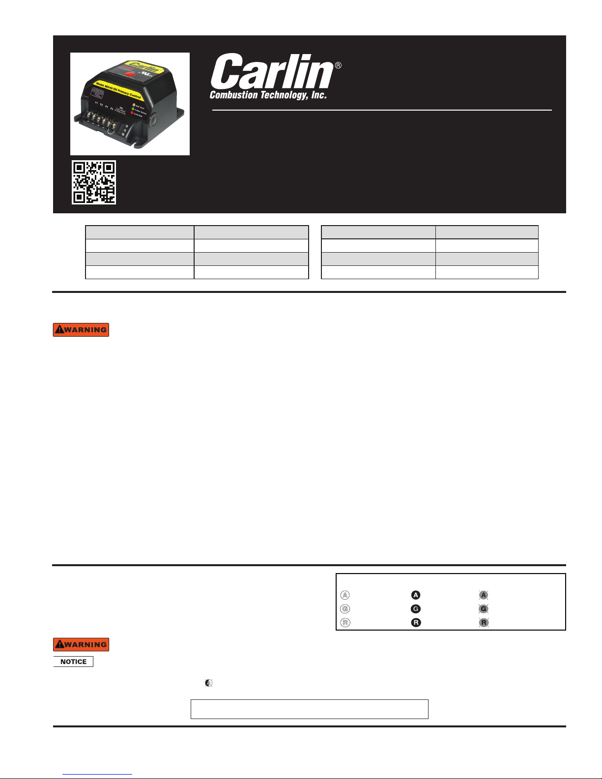
Model 48245 with Smart
Ignition – CAD Cell Oil
Primary Control Data Sheet
• Intermittent Duty when you need it,
Ignitor-saving Interrupted Duty when
you don’t
• Oil Pump Bleed Assist
• Recycle on Flame Failure
• Diagnostic LEDs
Status, lockout, flame
Power input (from limit circuit) 120 VAC, 60 HZ
Motor load
Ignitor load
Operating temperature limits
10 FLA / 60 LRA
120 VAC, 60 HZ, 500 VA
+32°F to +140°F
60 seconds
Storage temperature limits
Thermostat anticipator current
CAD cell resistance (with flame) R < 1500 OHMS
Agencies
• 45 or 15 second TFI
• Increased Flame Accuracy
• Thermostat/Aquastat Compatible
• Improved SMC Technology
zero bleed voltage during standby
• Works Well with Generators
Insensitive to frequency changes
-40°F to +185°F
0.1 A, AC
UL recognized (US & Canada)
Installing and Wiring
48245 control must be installed and serviced only by a qualified service technician.
1. Always disconnect power source before wiring to avoid electrical shock or damage to the control. All wiring must comply with
applicable codes and ordinances.
2. Thermostat terminals (T-T) provide a current source. Never apply external power to these terminals under any circumstances.
Mounting
• The control may be mounted on a 4" x 4" junction box in any convenient location on the burner, furnace or wall. The location
must not exceed the ambient temperature limit, 140°F.
Wiring
• Wiring must comply with local and national electrical codes, and with the wiring diagram.
• Individual or bundled neutrals may be attached to any L2 terminal.
Field checks
1. Select preferred TFI by 1) leave jumper in for 45 seconds or 2) remove jumper for 15 seconds. IMPORTANT: TFI change oc-
curs on next call for heat.
2. Safety timing (TFI) test – Remove one CAD cell wire (F-F). Start burner. The control should lockout within the TFI time limit.
Replace CAD cell wire.
3. Flame failure test – Start burner. After flame is established (after TFI period), close the oil supply hand valve. This will cause a
flame failure sequence as described in the Startup & Operation section of this data sheet. Under recycle, please read “Smart
Ignition” on page 3.
4. If control does not operate as described, check the wiring.
Startup & Operation
Three wire or four wire conguration
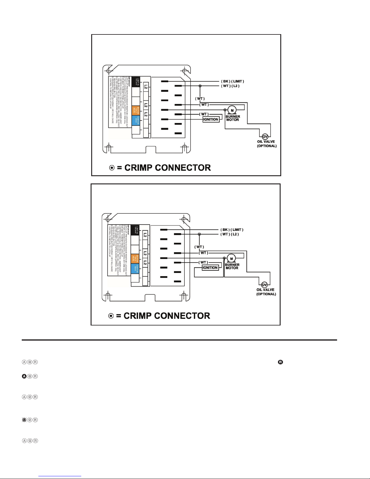
• See Figure 1 for wiring diagram for four-wire conguration
(Smart Ignition)
• See Figure 2 for wiring diagram for three-wire conguration
Do not start the burner if the combustion chamber contains oil or oil vapor.
Per UL requirements, the control will not turn on if the CAD cell senses flame during the self-test. If the CAD cell sees
Model 48245 Diagnostic LEDs
– Amber OFF – Amber ON – Amber FLASHING
– Green OFF – Green ON – Green FLASHING
– Red OFF – Red ON – Red FLASHING
light (flame) at the beginning of a cycle, the control will remain in self-test mode until the CAD cell no longer senses light (flame).
The amber LED will blink momentarily
every 3 to 4 seconds and green LED will be on or flashing.
Tech Support (800) 989-2275 www.carlincombustion.com
SEE WIRING DIAGRAM ON NEXT PAGE
Page 2
Wiring
Figure 1: 4-wire 48245 Oil Primary Control
(activates Smart Ignition)
Figure 2: 3-wire 48245 Oil Primary Control
(does not activate Smart Ignition)
Startup & Operation
Power ON Open all manual oil line valves. Close the line switch. (If Red LED turn on constant
Self-test 1 The control performs a “boot-up” test to verify internal operation each time power is applied to the L1 wire.
The amber LED turns on and the test continues for about 5 seconds. If the test fails, the control turns the
Stand-by (No call for heat) If Self-test 1 is successful, amber LED turns off and control waits for heat call.
Call for Set thermostat to call for heat. Thermostat circuit must be closed and power coming to black wire from
heat limit circuit.
Self-test 2 If a failure occurs in this self-check, the control won’t start and the amber LED blinks 1 second on, 4 sec-
Burner ON After the self-test, amber LED turns off. The ignitor starts, followed 2 seconds later by the motor. Wired as
© Copyright 2016 - Carlin Combustion Technology, Inc. MN48245E 021517
See next page to reset.)
amber LED off and repeats this test sequence until successful.
onds off, until serviced or the problem clears. These failures include CAD cell seeing light, internal failure,
or line voltage <90V. See service section.
3-wire, the ignitor and motor come on at the same time.
Three wire or four wire conguration (continued)
, control is in lockout.
Page 3
Startup & Operation Four wire conguration
Do not start the burner if the combustion chamber contains oil or oil vapor.
Per UL requirements, the control will not turn on if the CAD cell senses flame during the self-test. If the CAD cell sees
light (flame) at the beginning of a cycle, the control will remain in self-test mode until the CAD cell no longer senses light (flame).
The amber LED will blink momentarily
heat power from the limit circuit).
Pump To enter pump prime: 1. Start a CFH cycle. During Pre-Ignition, press Reset until motor turns
Prime off (10 seconds), then release the button. When motor turns back on, within 5 seconds, press the Reset button
Optional Pump Prime notes: 1) If Pump Prime is lost, press Reset for 1 second and release, then if the
To Reset Push in and hold reset button for 2 seconds, then release.
(Flame Failure) control waits for 65 seconds, Red LED goes off, then begins again at Self Test 2.
every 3 to 4 seconds and green LED will be on or flashing.
Power ON Open all manual oil line valves. Close the line switch. (If Red LED turn on constant , control is in lockout.
Self-test 1 The control performs a “boot-up” test to verify internal operation each time power is applied to the black
Stand-by (No call for heat) If Self-test 1 is successful, amber LED turns off and control waits for heat call.
Call for Set thermostat to call for heat. Thermostat circuit must be closed (and black wire must receive
Self-test 2 If a failure occurs in this self-check, the control won’t start and the amber LED blinks 1 second on, 4 sec-
Burner ON After the self-test, amber LED turns off. The ignitor starts, followed 2 seconds later by the motor.
TFI The CAD cell must sense flame within the TFI time limit (trial for ignition). Insufficient flame puts control into
Run The burner continues firing during call for heat if the CAD cell is sensing flame. Only the green LED is on
Lockout If CAD cell does not sense flame within the TFI time limit after the burner starts, lockout occurs. The con-
Recycle If the CAD cell loses flame signal during operation (after the TFI), the Red LED flashes. Recycle:
Stand-by Control remains in stand-by mode until limit circuit sends power to the black wire and thermostat circuit
See below to reset.)
wire. The amber LED turns on and the test continues for about 5 seconds. If the test fails, the control turns
the amber LED off and repeats this test sequence until successful.
onds off, until serviced or the problem clears. These failures include CAD cell seeing light, internal failure,
or line voltage <90V. See service section.
until the amber LED starts to flash. You are in Pump Prime, release Reset button.
control is not in Pump Prime, restart the sequence. 2) If Reset is released before end of first 10 seconds,
the control returns to Standby and restarts another CFH cycle. 3) If reset is not pressed the second time,
a normal CFH cycle will continue. 4) If motor and igniter are on and amber LED is flashing, the control is in
Pump Prime. 5) Pump Prime will exit standby if flame is detected, or 60 seconds has elapsed, or loss of
TT or Limit, or Reset button is pressed.
lockout.
during normal running.
trol turns the red LED on constant and closes the alarm contact.
The 48245 control will retain lockout if power is interrupted.
If the green LED is blinking during a run, the flame is weak or unstable and may go into recycle.
closes (call for heat).
IMPORTANT: All four wires provided must be used to activate the Smart Ignition feature. The ignitor must be wired to
the control’s blue ignitor output terminal. See Figure 1 for Smart Ignition Wiring diagram
Smart Ignition runs in Intermittent Duty (aka “constant” duty) when needed to prevent loss of flame. But unlike any other primary control, Smart Ignition switches to Interrupted Duty when it can – to save wear and tear on the ignitor and electrodes.
How Smart Ignition Works:
The control initially works as an Interrupted Duty control. Following a 45-second Trial-for-Ignition period and a 45-second
Flame Stabilization period, the ignitor output is turned off.
If flame is lost at any time after the Trial-for-Ignition period, the control will recycle (60 - 65 seconds). Following this recycle,
the control will operate in Intermittent Duty mode for ten heat cycles. Following these ten cycles, the control will revert back
to Interrupted Duty and will remain in Interrupted Duty until another recycle event occurs.
The Best of All Worlds:
The Model 48245 with Smart Ignition ensures flame retention by providing intermittent duty ignition when required to prevent flame loss and it dramatically increases the ignitor and electrode life and saves energy by switching to interrupted
duty the remainder of the time.
To manually reset from Intermittent Mode: Open TT and depress the reset button until the amber LED turns on. Release the
reset button; the control is reset from the intermittent mode.
© Copyright 2016 - Carlin Combustion Technology, Inc. MN48245E 021517
Smart Ignition
Page 4

Service & Troubleshooting
Burner (control) will not come on
No power to control
• Check limit circuit to the control (at least 102 VAC).
• Check all electrical connections.
Control is in lockout
• Red LED will be on. Press the reset button for 2 sec-
• Green LED on, and amber LED blinking 1 second
If the amber LED goes OFF, the control is OK, and;
• light is leaking into the burner housing, or
• CAD cell is defective, or
• there is a problem with the CAD cell wiring or holder.
• If appliance was recently shut down, CAD cell may
To troubleshoot:
• Attach multimeter to monitor CAD cell resistance.
• Check for stray light by measuring the CAD cell
onds.
CAD cell seeing light
on, 4 seconds off. Remove one yellow lead from
FF terminals. If the amber LED remains flashing, the
control is defective.
see residual hot spots in chamber.
Dark resistance should be over 50K ohms, and
room light resistance (control flipped open) should
be at most 10K ohms Replace cell if necessary, or
reinstall and close the burner housing.
resistance looking into the inactive combustion
chamber. It should read at least 50 kohms.
Other no start problems
If the CAD cell is OK, and the amber LED still blinks
• Line voltage <90 VAC (amber LED flashes uniquely,
• Internal fault. If CAD cell and line voltage are OK, the
Repeated flame failures (
Check for:
• CAD cell is defective. Replace.
• Air leaking into oil line causing flame out. Check oil
• Defective nozzle causing flame to be erratic.
• Excessive airflow or draft causing flame to leave
• Excessive back pressure causing flame to be er-
Control locks out at end of TFI (
Check for:
• No oil to burner. Check oil supply, filters, lines.
• Shorted electrodes. Inspect for cracked porcelain
• Poor spark. Check electrode spacing and condition
• Nozzle clogged. Replace nozzle.
• Airflow too high. Check air band setting.
• Ignitor module defective. Replace if no spark.
• CAD cell defective
• Oil valve (if used) stuck in closed position.
• Check wiring connections.
• Weak or unstable flame.
• Check ohms.
• Check CO
1 second on, 4 seconds off, the other possible failures
include:
1 second on, 1/2 second off, 1 second on, 3 seconds off, then repeats). Check line voltage.
issue may be an internal fault. Replace the control.
flashing red LED)
line connections and filter gasket.
Change nozzle.
burner head. Check for proper air band setting and
draft.
ratic. Check appliance and flue for sooting/plugging.
red LED on)
and replace as needed.
per burner manual. Replace or realign if necessary.
Blinking Green LED
level.
2
FROZEN PIPES/WATER DAMAGE: This is not a freeze protection device. Suitable freeze protection monitoring or
other precautions are recommended to protect against ruptured pipes/water damage caused by fuel outage, safety
related fault conditions, or equipment failures.
© Copyright 2016 - Carlin Combustion Technology, Inc. MN48245E 021517
 Loading...