

Instruction manual
™
Installer/servicer — Except where specifi cally stated other-
wise, this manual must be used only by a qualifi ed service
technician. Failure to comply with this or other requirements
in this manual could result in severe personal injury, death or
substantial property damage.
User — Refer only to User care and maintenance on back
page for information regarding operation of this burner. The
burner Instruction Manual is intended only for your service
technician. The burner and heat exchanger must be inspected
and started at least annually by your service technician.
Ratings
Input: 201CRD.......................................... 2.50 to 5.00 GPH
301CRD (3¼’’ air cone) ................. 3.00 to 6.00 GPH
301CRD (3½’’ air cone) ................. 4.00 to 7.00 GPH
Fuels: U.S. ........................................ No. 1 or No. 2 Fuel oil
Canada .............No. 1 Stove oil or No. 2 Heating oil
Fuel unit: ....................................................................... Suntec
.................................100 to 150 PSIG nozzle pressure
...............................................Factory set at 150 PSIG
Electrical: Power ................................240V, 50/60 Hz, 1-Phase
Motor........................ Carlin PSC, 1/4 HP, 3450 RPM
Total current at 240V, 50/60 Hz, 1-Phase:
201CRD ............................... Approx. 1.6 amps
301CRD ............................... Approx. 1.6 amps
Ignition: ....... Carlin Model 42000 electronic — 14,000 volts
Control: ........................................U.L. primary safety control
Agencies: ....................................... UL Listed (US and Canada)
© Copyright 2010 — Carlin Combustion Technology, Inc.
Carlin Combustion Technology, Inc.
70 Maple Street East Longmeadow, MA 01028
Ph 413-525-7700 Fx 413-525-8306
TECH SUPPORT 800-989-2275
carlincombustion.com

Model 201CRD & 301CRD 240-VAC Advanced oil burners — Instruction manual
PLEASE read this fi rst . . .
Contents
PLEASE read this fi rst .............................................................2
General information ................................................................3
Before installing or servicing . . .
Codes and standards ..............................................................3
1. 201 & 301 Oil nozzles ........................................................3
2. Prepare site • assemble burner • mount burner ......4
3. Prepare burner .................................................................10
4. Wire burner • start burner –
50240 primary control .....................................................16
60240 primary control .....................................................18
5. Adjustment and verifi cation .............................................20
6. Annual start-up and service ............................................21
7. Repair parts .....................................................................22
8. Maintenance/service procedures ....................................24
Warranty ...............................................................................27
User care and maintenance .................................... Rear cover
Special attention fl ags . . .
Please pay particular attention to the following when you see them throughout this manual.
Notifi es you of hazards that WILL cause severe personal injury,
death or substantial property damage.
Should overheating occur:
(1) Shut off the oil supply to the burner.
(2) Do not shut off the control switch to the circulator
or blower.
Follow the guidelines below to avoid potential severe
personal injury, death or substantial property damage.
Installer/service technician . . .
• Read all instructions before proceeding. Perform all procedures, and
in the order given to avoid potential of severe personal injury, death or
substantial property damage.
• Before leaving the site after startup or service, review the User care and
maintenance page with the user. Make the user aware of all potential
hazards and perform the training outlined below.
Installer/service technician — Train the user . . .
• To properly operate the burner/appliance per this manual and the
appliance instructions. See User care and maintenance.
• To keep this manual at or near the burner/appliance for ready access
by the user and service technician.
• To contact the service technician or oil dealer if he encounters problems
with the burner/appliance.
• To keep the appliance space free of fl ammable liquids or vapors and
other combustible materials.
• To never use laundry products, paints, varnishes or other chemicals in
the room occupied by the burner/appliance.
• To contact the service technician at least annually for startup and
burner/appliance service.
– 2 –
Notifi es you of hazards that CAN cause severe personal injury,
death or substantial property damage.
Notifi es you of hazards that WILL or CAN cause minor personal
injury or property damage.
Notifi es you of special instructions on installation, operation or
maintenance that are important, but are not normally related
to injury or property damage hazards.
When servicing the burner . . .
• Disconnect electrical supply to burner before attempting to service to
avoid electrical shock or possible injury from moving parts.
• Burner and appliance components can be extremely hot. Allow all
parts to cool before attempting to handle or service to avoid potential
of severe burns.
Carlin part number MN2301A Rev. 10/21/10
Model 201CRD & 301CRD 240-VAC Advanced oil burners — Instruction manual
General information 1. 201 & 301 Oil nozzles
Burner applications
Follow all instructions in this manual, the primary control data sheet and
the appliance manual.
Verify the burner is correct for the appliance being used and for all applicable codes/standards.
Damage or shortage claims
The consignee of the shipment must fi le damage or shortage claims immediately against the transportation company.
When calling or writing about the burner:
Please provide us with the UL serial number and burner model number
to assist us in locating information. This information can be helpful when
troubleshooting or obtaining replacement parts.
Codes and standards
Certifi cation
201CRD and 301CRD burners are U.L. listed for the U.S. and Canada,
certifi ed to comply with ANSI/UL 296, for use with #1 or #2 heating oil
(per standard ASTM D396).
Burner labels list compliance, when required, with special local, state or
provincial approvals.
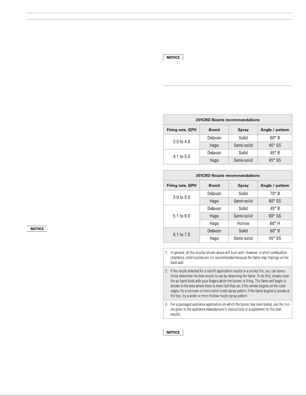
Use the selections in Table 1 ONLY when heating appliance
manufacturer specifi c nozzle selection data is not available,
either in the appliance manual or the Carlin OEM Spec Guide.
Follow all instructions provided with the appliance.
Table 1 Apply the guidelines below to select a nozzle when
appliance-specifi c nozzle data is not available from the
manufacturer or in the Carlin OEM Spec Guide. See
notes at end of table for application tips.
Install this burner in accordance with all local codes and
authorities having jurisdiction. Regulations of these authorities take precedence over the general instructions provided
in this manual.
United States installations
Burner/appliance installations in the United States must comply with the
latest editions of NFPA 31 (Standard for the Installation of Oil-Burning
Equipment), ANSI/NFPA 70 (National Electrical Code), and all applicable
local codes.
Canadian installations
Burner/appliance installations in Canada must comply with the latest editions
of CSA B139 (Installation Code for Oil Burning Equipment), CSA standard
C22, Part 1 (Canadian Electrical Code), and all applicable local codes.
The fuel unit is factory-set at 150 PSIG. The
nozzle selected must consider the fuel unit pressure. See
nozzle sizing in Table 4, page 13.
Carlin part number MN2301A Rev. 10/21/10
– 3 –

Model 201CRD & 301CRD 240-VAC Advanced oil burners — Instruction manual
2. Prepare site • assemble burner • mount burner
Vent system
General
Do not install this burner unless you have verifi ed the
entire vent system and the appliance are in good condition and comply with all applicable codes.
• The vent and chimney must be sized and constructed
in accordance with all applicable codes.
• Do not install or use an existing manual damper in
the breeching (vent connector) or chimney.
• Do not connect the appliance vent connector to a
chimney or vent serving a fi replace, incinerator or
solid-fuel-burning apparatus.
• In a cold climate, do not vent into a masonry chimney
that has one or more sides exposed to the outside.
You must install a listed stainless steel liner in the
chimney to vent the fl ue products.
• A defective vent system could result in severe personal
injury, death or substantial property damage.
Prepare vent/chimney
• Secure all metal vent joints with screws, following the vent manufacturer’s instructions.
• Seal all joints in the vent system and chimney.
• Repair masonry chimney lining and repair all mortar joints as
needed.
• Install a double-acting barometric draft regulator in the vent piping if
specifi ed in the appliance manual. (The damper must be located in
the same space as the appliance.)
• Provide support for the vent piping. Do not rest the weight of any of
the vent piping on the appliance fl ue outlet.
Combustion and ventilation air
openings
General
Check appliance manual and applicable codes for required sizing,
design and placement of combustion/ventilation air openings. You can
use the following general guidelines, taken from NFPA 31, provided
they meet all local requirements.
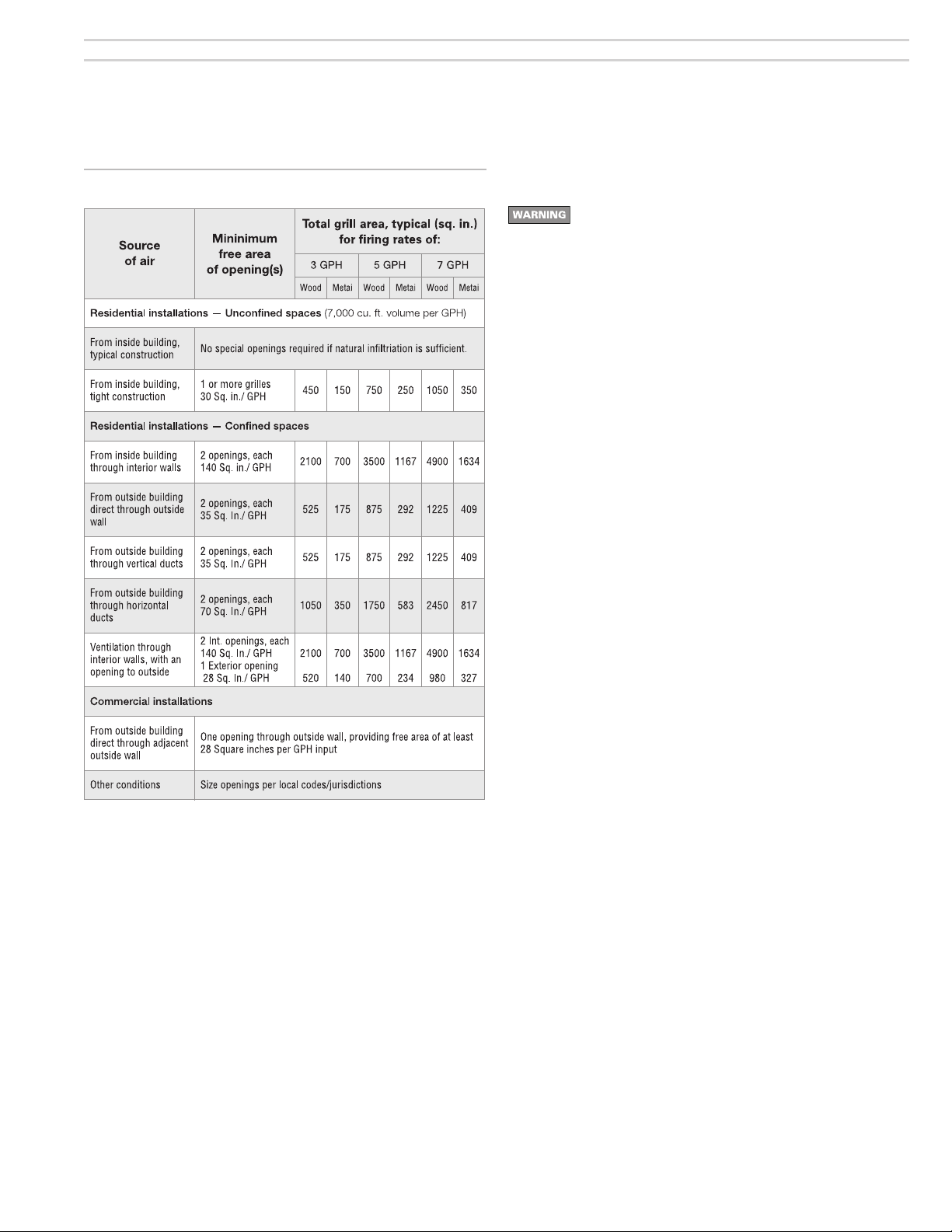
Free area — Louvers and screens
• Air opening sizes are always given in free area. This means after
deduction for louver obstruction. If you can’t fi nd the louver reduction
for the grilles used, assume free area is 20% of total for wood louvers,
or 60% of total for metal louvers.
• Screens can be no fi ner than ¼-inch mesh, and must be accessible
for cleaning.
Residential installation air openings
Residential — Unconfi ned spaces (at least 7,000 cubic feet per GPH)
• An unconfi ned space means a room with at least 7,000 cubic feet volume for
each GPH input (or 50 cubic feet per MBH) of all appliances in the room.
Example: For a boiler room housing a 6.00 GPH input burner/appliance, multiply
6 times 7,000 cubic feet, equals 42,000 cubic feet. The room must have a
volume of 42,000 cubic feet to be classifi ed as an unconfi ned space. (If the
boiler room has an 8-foot ceiling height, the room would have to have 5,250
square feet, or about 73 feet square.)
• Most boiler rooms do not provide this much volume, and must be treated as
confi ned spaces, requiring dedicated combustion air openings, sized as in the
following.
• Open residential basements and crawl spaces are often large enough, and
will generally allow enough air infi ltration, so special provisions will seldom be
required.
• If the building is tightly constructed, you will have to provide outside air openings into the building regardless of the boiler room volume. The total free area
of these openings must be at least 1 square inch per 5,000 Btuh (28 square
inches per GPH) of all appliances in the space.
• See Table 2 for a summary.
Residential — Confi ned spaces (less than 7,000 cubic feet per GPH)
• Air taken from inside building only —
• Provide two openings — one near the fl oor, the other near the ceiling. Provide
free area of 140 square inches per GPH input.
• If the building is tightly constructed, provide dedicated air opening(s) into the
building with at least 30 square inches free area per GPH.
• Air taken from outside —
• Direct through outside wall or vertical ducts:
Provide two openings — one near the fl oor, the other near the ceiling. Provide
free area of at least 35 square inches per GPH input.
• Through horizontal ducts:
Provide two openings — one near the fl oor, the other near the ceiling. Provide
free area of at least 70 square inches per GPH input.
• Ventilation air from inside, with combustion air from outside
• Size openings to interior to provide 140 square inches free area per GPH
input.
• Size the outside combustion air duct to provide 28 square inches free area per
GPH.
• See Table 2 for a summary.
Commercial installation air openings
Commercial — Air openings directly from outside to boiler room
• Provide one opening that provides a free area of at least 28 square inches
per GPH input.
Example: For a boiler room housing boilers totalling 10 GPH fuel oil input,
the area opening must have a free area of no less than 10 times 28, or
280 square inches. If the opening is wood louvered, divide by 20%, or the
opening must be 1400 square inches (about 38 inches by 38 inches). If
the opening is metal louvered, divide by 60%, or the opening must be 467
square inches (about 22 inches by 22 inches).
– 4 –
Carlin part number MN2301A Rev. 10/21/10
Model 201CRD & 301CRD 240-VAC Advanced oil burners — Instruction manual
2. Prepare site • assemble burner • mount burner (continued)
Table 2 Minimum combustion/ventilation air openings
Combustion/ventilation air checklist
The burner may operate successfully under momentary
downdraft conditions, but sustained downdraft is unsafe.
• This can occur with an inadequate or incorrectly installed
chimney/vent.
• It can also occur in rooms/buildings equipped with exhaust
fans or unsealed return air ducts.
• Always check operation of the burner under all conditions
to verify vent system operates correctly.
• You may have to interlock the burner with exhaust fans to
shut burner off when fan operates; or provide make-up air
to the appliance room suffi cient to prevent any negative
pressure in the space.
• Failure to correct downdraft or negative room pressure
operation could result in severe personal injury, death or
substantial property damage.
Verify that openings are unobstructed.
Verify that appliance space and air source spaces are free of:
• Gasoline or other fl ammable liquids or vapors.
• Combustible materials.
• Air contaminants and chemicals, such as laundry products, paint, thinner,
varnish, etc.
Confi rm with the building owner that the area will be kept free of these
materials at all times and that air openings will be kept unobstructed.
Verify clearances
Verify that the burner/appliance will maintain all required clearances:
Verify clearance from combustible construction, as specifi ed by appliance
manufacturer and local codes.
Verify clearances for service and maintenance as required in the appliance
manual and applicable codes.
Vent system components must maintain all necessary clearances to
combustible construction, including the correct design of thimbles and
insulation where penetrating combustible walls.
Carlin part number MN2301A Rev. 10/21/10
– 5 –
Model 201CRD & 301CRD 240-VAC Advanced oil burners — Instruction manual
2. Prepare site • assemble burner • mount burner (continued)
Verify combustion chamber
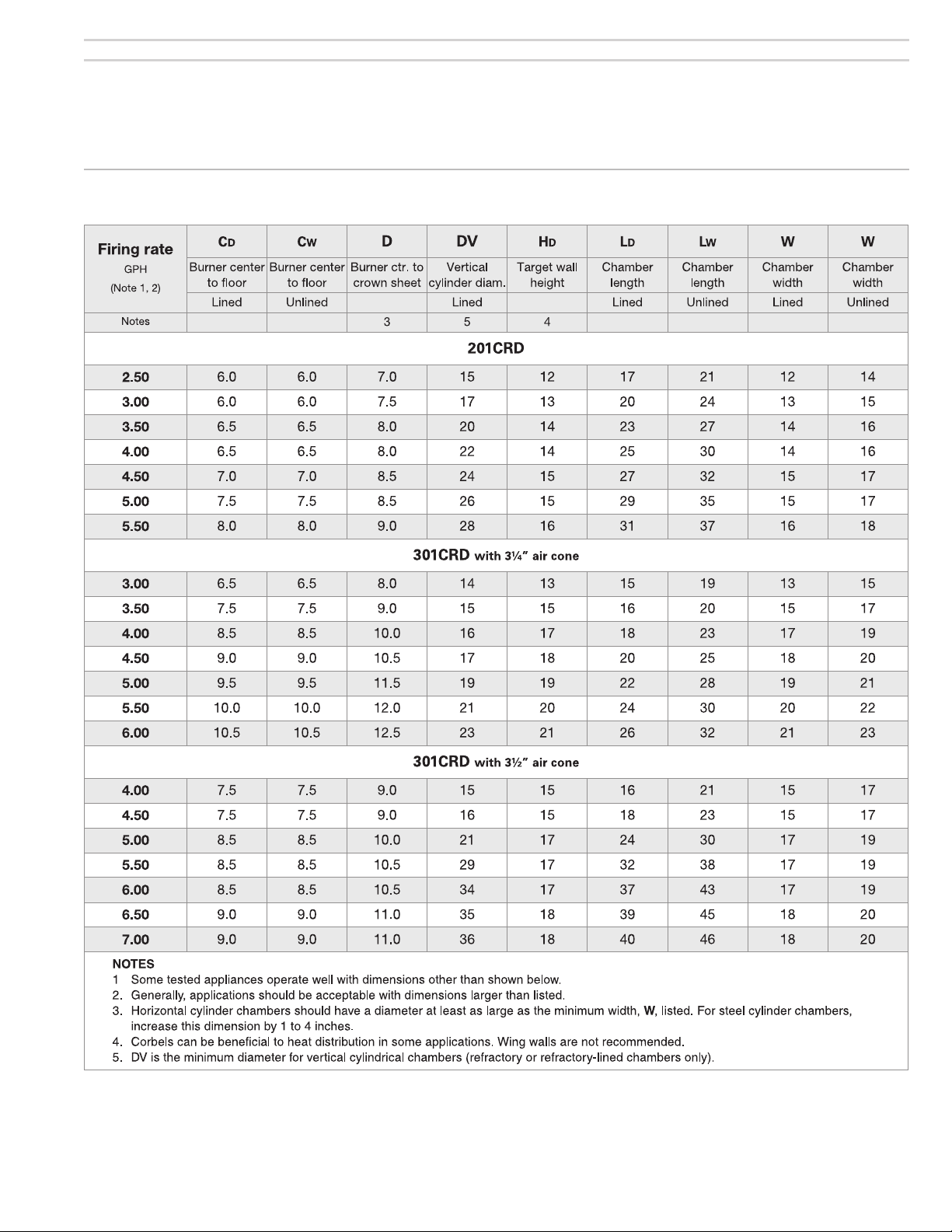
Chamber dimensions and construction
• If retrofi tting the burner to an appliance, install the burner in accordance
with the appliance instruction manual, when available. If no specifi c
application data is available from the appliance manufacturer, read the
guidelines below to check whether the burner is likely to work acceptably
in the application.
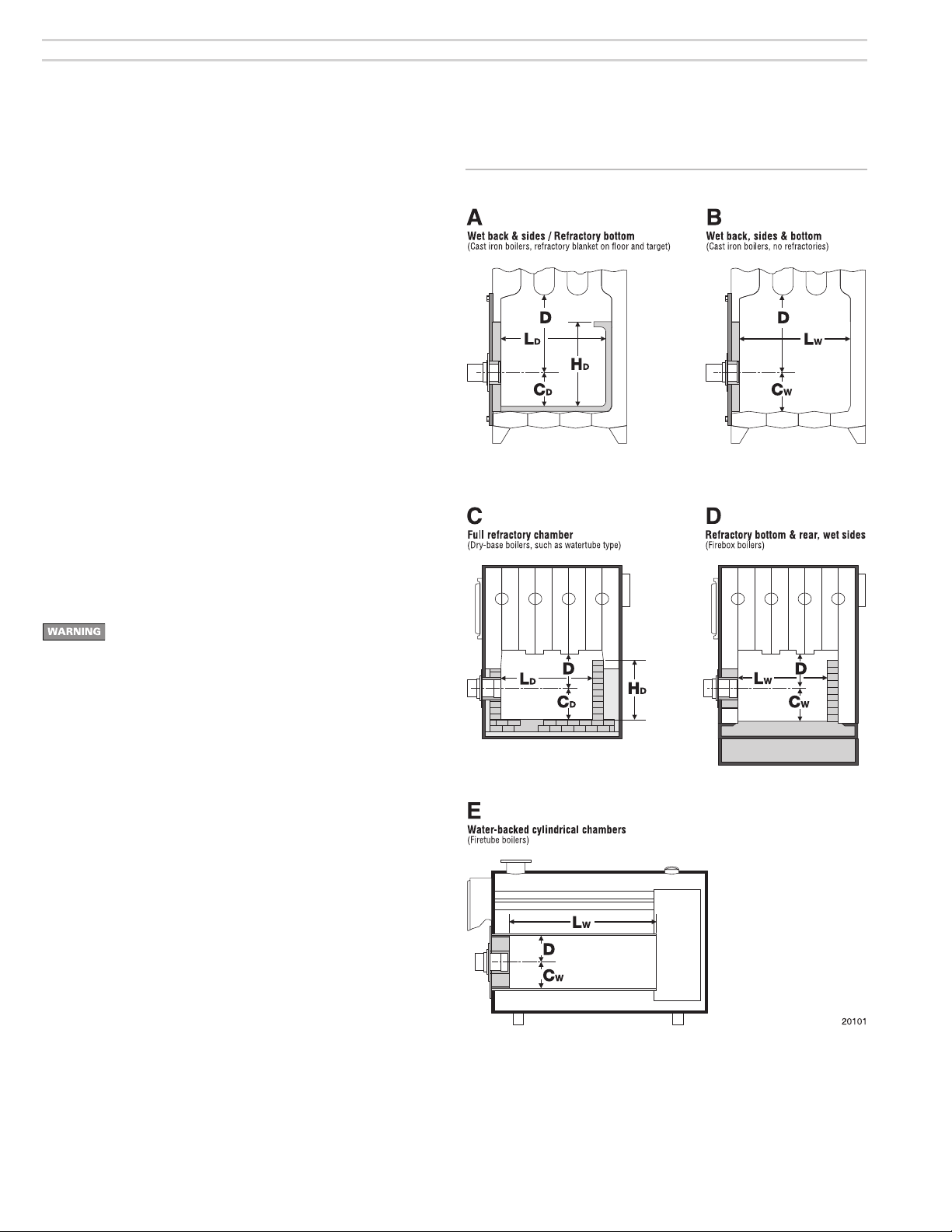
• Illustrations A to E in Figure 1 show different chamber confi gurations, with
and without refractory linings. The chamber dimensions listed in Table 3
depend on whether the chamber is lined or water-backed, as shown.
• Do not attempt to fi re the burner in a chamber with dimensions smaller
than shown in Table 3 unless the application has been specifi cally tested
and listed by the appliance manufacturer and/or Carlin.
• Chambers with dimensions larger than shown in Table 3 should not have
much effect on combustion/performance.
General guidelines
• Clean all appliance fl ues and heating surfaces thoroughly, removing all
soot and scale.
• Seal all joints and gaps using furnace cement to prevent excess air
infi ltration.
Read the WARNING on page 26 before handling or applying
ceramic fi ber materials.
Figure 1 Combustion chamber confi gurations, typical
Using chamber linings
• When using refractory liners or lightweight chambers, use insulating-type
refractory rated 2600°F minimum, or as specifi ed by the appliance manufacturer.
• You must install a target wall liner if fl ame length is close to the length of
the chamber.
• Use a fl oor liner when possible. The fl oor liner will improve fi ring in most
applications. Extend fl oor liner 3 to 4 inches up the side walls.
• Target wall liners — Extend target wall liners at least 3 to 4 inches above
the center of the fl ame corbel the top 1½ to 2½ inches deep.
• Use preformed chamber liners when available. Lining the fl oor and target
wall water-backed combustion chambers with lightweight insulating refractory will accomplish the same.
• When converting coal-fi red units, install a combustion chamber in the ashpit
area, or fi ll the ashpit with sand up to 2 inches above the “mud ring” of the
boiler (fi ring through the door). Install a lightweight refractory liner on the
target wall as in Figure 2D.
– 6 –
Carlin part number MN2301A Rev. 10/21/10
Model 201CRD & 301CRD 240-VAC Advanced oil burners — Instruction manual
2. Prepare site • assemble burner • mount burner (continued)
Table 3 201CRD and 301CRD Minimum combustion chamber dimensions (all dimensions in inches) - See Figure 1 for combustion
chamber confi gurations
Carlin part number MN2301A Rev. 10/21/10
– 7 –

Model 201CRD & 301CRD 240-VAC Advanced oil burners — Instruction manual
2. Prepare site • assemble burner • mount burner (continued)
Inspect burner and components
General
• Check the air tube length. Verify the usable length of the tube UTL will be
long enough (see “Mount burner in appliance”).
• Visually inspect all burner components and wiring.
• Verify that wiring is intact and leads are securely connected.
• Verify that all burner components are in good condition.
Do not install or operate the burner if any component is
damaged or if burner does not comply with other guidelines
of this manual and the appliance manual.
Install/check burner fl ange
Welded-fl ange burners
1. Verify the bolt pattern on the appliance chamber matches the fl ange pattern.
2. Verify the insertion depth (UTL) matches the depth of the appliance opening (so the end of the air tube is fl ush with, or slightly short of, the inside
surface of the combustion chamber).
Figure 2 Standard adjustable fl ange (universal fl ange)
Figure 3 Adjustable forced draft fl ange
Burners with adjustable fl anges
1. See Figure 2 for standard adjustable fl ange (universal fl ange) dimensions.
See Figure 3 for adjustable forced draft fl ange dimensions.
Verify the fl ange mounting slots line up with the appliance bolts.
2. Slip the adjustable fl ange onto the air tube.
3. Measure the distance from the inside of the combustion chamber to the
outside of the appliance mounting plate.
4. Position the adjustable fl ange at this distance from the end of the air
tube.
5. Tighten the locking screws fi nger tight.
6. Insert the air tube/fl ange assembly into the appliance opening and level
the air tube with a spirit level (see Figure 4). Adjust fl ange if needed.
7. The end of the air tube should be fl ush, or almost fl ush, with the inside of
the combustion chamber wall.
8. Verify the air tube is level and inserted the correct depth. Adjust if necessary.
Then tighten the fl ange locking screws securely.
9. Remove the fl ange/air tube assembly from the opening.
10. Forced draft adjustable fl anges: Use ¼-inch diameter fi berglass sealing
rope, as shown in Figure 3, to seal the fl ange to the air tube.
A forced draft adjustable fl ange must be sealed to the air
tube to prevent possible leakage of fl ue products. Failure
to comply could result in severe personal injury, death or
substantial property damage.
Figure 4 Mark insertion depth on air tube when using universal
fl ange mounting
– 8 –
Carlin part number MN2301A Rev. 10/21/10
Model 201CRD & 301CRD 240-VAC Advanced oil burners — Instruction manual
2. Prepare site • assemble burner • mount burner (continued)
Pedestal-mounted burners
1. Check the diameter of the appliance opening. If larger than 4½ inches,
rebuild the opening so the open is reduced to 4½ inches maximum.
2. Insert the air tube into the appliance opening as in Figure 4. Do not attach
air tube to housing yet.
3. Slide the tube in until the end of the tube is fl ush with, or up to ¼ inch short
of, the inside of the combustion chamber.
4. Level the air tube using a spirit level.
5. Mark the air tube position with a pen or pencil around the circumference
of the tube.
6. Remove air tube from the opening
Attach air tube to housing
1. See Figure 5. Loosen the four hex set screws on the top front of the burner
chassis.
2. Open the ignitor cover plate by loosening the retainer screw on the left side
of the burner housing.
3. Swing the ignitor plate open.
4. Locate the drip hole in the burner air cone (301 burners) or throttle ring
(201 burners). Rotate the air tube so the drip hole is at the bottom.
5. Insert the air tube into the housing.
6. Make sure the air tube is inserted completely, butting against the air tube
socket ledge. If necessary, tap on the end of the air tube with a block of
wood until properly seated.
7. Secure the air tube by tightening the four hex set screws on the top front
of the burner housing.
On burners with welded fl anges, you can bolt the air tube/
fl ange to the appliance fi rst — then attach the housing to
air tube.
Figure 5 Attaching air tube to burner housing
Mount burner in appliance
Welded fl ange-mounted burner
1. Place gasket over burner air tube and insert burner into appliance opening.
Secure in place with hardware supplied with appliance.
Universal fl ange or pedestal mount — these insertion methods
are intended only for negative overfi re pressure. For pressurized fi ring, you must obtain a burner with a welded fl ange,
designed for use with the specifi c appliance. Failure to comply
could result in severe personal injury, death or substantial
property damage.
Adjustable fl ange-mounted burner
1. Place gasket over burner air tube.
2. Insert burner into appliance.
3. Verify burner is seated level and straight. Adjust fl ange slightly if necessary.
4. Secure fl ange to appliance with hardware supplied with appliance.
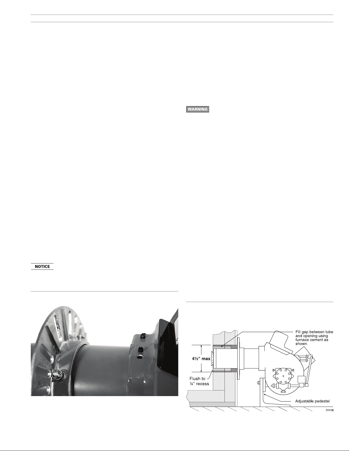
Pedestal-mounted burner
1. Assemble the pedestal to the burner and tighten the bolt. Insert a screw
into each of the two holes in the pedestal feet if needed to level the assembly.
2. Adjust the pedestal so the air tube is level and the center of the tube is at
the same height as the center of the appliance opening.
3. Tighten the pedestal bolt.
4. Insert the burner/air tube into the appliance opening until pen/pencil line is
even with appliance front (so end of air tube is fl ush with, or slightly short
of, the inside of the chamber).
5. Seal the space around the air tube with furnace cement or equivalent
(Figure 6).
Carlin part number MN2301A Rev. 10/21/10
Figure 6 Seal opening around burner air tube when pedestal
mounting (burner shown with tube attached to housing
and installed)
– 9 –

Model 201CRD & 301CRD 240-VAC Advanced oil burners — Instruction manual
3. Prepare burner
Removing/installing head assembly
Use care when handling burner components after the burner
has been fi ring. Components can be hot and could cause
severe personal injury.
Removing the combustion head assembly
You will need to remove the combustion head assembly for inspection of
the assembly, replacement of the oil nozzle or adjustment of electrodes.
To remove the assembly:
1. Loosen the screw on the left side of the burner housing that secures the
ignitor plate in place. Swing the ignitor plate open.
2. See Figure 7.
3. Unscrew the oil line fi tting from the elbow at the end of the oil tube.
4. Remove the combustion head assembly by pulling the assembly up and
out of the housing.
7. Handle the assembly with care to avoid bending or moving the electrodes,
or damaging the electrode ceramic insulators.
8. Inspect the gasket on the bottom of the ignitor plate. The gasket prevents
air from escaping from the housing. Replace the gasket if not in good
condition.
9. Inspect the ignitor contact clips. Clean or replace if necessary to ensure
reliable contact with the electrodes.
Figure 7 Removing/inserting combustion head assembly
Figure 8 Inserting combustion head assembly
Replacing the combustion head assembly
To replace the combustion head assembly, reverse the sequence above.
• Make sure the oil line bracket seats into the slot on the adjusting screw.
• See Figure 8. You will have to lift the end of the assembly to guide it through
the throttle ring or air cone at the end of the air tube. DO NOT FORCE.
Use care when tightening the oil line fi tting to oil tube extension.
Tighten securely, but do not cross-thread or over-tighten.
– 10 –
Carlin part number MN2301A Rev. 10/21/10

Model 201CRD & 301CRD 240-VAC Advanced oil burners — Instruction manual
3. Prepare burner (continued)
Install nozzle/check electrodes
1. Loosen the clamp screw on the retention ring assembly (see Figure 9,
step 1). Slide the retention ring assembly off of the nozzle adapter.
2. Install and tighten the nozzle listed in the appliance instruction manual or
Carlin OEM Spec Guide.
3. If nozzle information is not available, begin with the nozzle listed in Table 1,
page 3. (You may have to change the nozzle later if combustion results are
not acceptable.)
3. Hold the nozzle adapter securely as shown in Figure 9, steps 2 and 4, when
removing or replacing the nozzle. Take care not to damage the electrode
insulators or to bend the electrodes in the process.
Inspect the nozzle adapter before replacing the nozzle. If the
threads have been damaged or show score marks, replace
the nozzle line/adapter assembly.
4. Install the retention ring assembly by slipping one of the riveted arms
through the gap between the electrode tips. Align this arm straight up, with
the ring clamp fi rmly against the nozzle adapter shoulder (see Figure 10).
Then tighten the clamping screw.
5. Check the electrodes and reposition if necessary. Position the electrodes
as shown in Figure 10. These settings are critical in ensuring a reliable
ignition. Once the electrodes are set, check all clamps to be sure they are
securely tightened.
6. Insert the combustion head/nozzle assembly into the burner.
Figure 9 Replacing the oil nozzle —
1 – Remove retention ring from nozzle adapter
2 – Support the assembly carefully and remove the nozzle
using 5/8-inch and 3/4-inch open-end wrenches.
3 – Insert and fi nger-tighten the new nozzle.
4 – Support the assembly and tighten the nozzle using the
open-end wrenches.
NOTE: Do Not over tighten.
Figure 10 Electrode sett ings
Carlin part number MN2301A Rev. 10/21/10
– 11 –

Model 201CRD & 301CRD 240-VAC Advanced oil burners — Instruction manual
3. Prepare burner (continued)
Set initial burner air settings
Combustion head (“A” dimension)
1. The combustion head adjusting screw is used to set the spacing between
the retention ring and throttle ring (or air cone), regulating how much air
passes around the retention ring.
2. See Figure 11.
3. Rotate the head adjusting screw until the distance from the housing detent
to the beginning of the scale equals the value given in Table 4, page 13
(“A” dimension).
Air band
1. See Figure 12. Loosen the air band locking screw and rotate the air band
until the opening equals the percent opening given in Table 4, page 13.
Final adjustments
1. The burner is now adjusted to the approximate air settings for the fi ring
rate chosen.
2. When you check combustion with instruments during start-up or servicing,
you may have to adjust the head and/or air band slightly to achieve the
desired effi ciency.
• Increase the combustion head setting (“A” dimension) to increase air. If
additional adjustment is needed, open the air band slightly.
• Decrease the combustion head setting (“A” dimension) to decrease air. If
additional adjustment is needed, close the air band slightly.
3. See “Adjust burner using test instruments,” page 20.
4. Note that positive pressure overfi re will reduce air fl ow, requiring more air
opening.
Figure 12 Air band setting
Figure 13 Combustion head/air tube combinations, typical
Figure 11 Combustion head setting
– 12 –
Carlin part number MN2301A Rev. 10/21/10

Model 201CRD & 301CRD 240-VAC Advanced oil burners — Instruction manual
3. Prepare burner (continued)
Table 4 Approximate air band and combustion head settings
• Check all connections and joints to ensure they are air-tight.
• Use fl are fi ttings. DO NOT use compression fi ttings.
• Never use pipe sealing tape. Fragments can break off and plug fuel line
components.
• Install a shut-off valve at the tank and one near the burner. (Use fusible
handle design valves when possible or when required by codes.)
• Install a large capacity fuel fi lter (rated for 50 microns or less) near the
burner.
Fuel supply to multiple burners
• When possible, use separate fuel supply lines for each oil burner. Using
manifolded oil supply lines can create problems. If the lines are undersized,
operating vacuum will exceed limits. If the lines are oversized, fuel units
may have diffi culty priming. Because the lines must be sized to handle the
capacity of all the burners, the line size will almost always be too large
when only a single burner is running.
• If manifolding cannot be avoided, carefully size the lines following the fuel
units manufacturer’s instructions.
Fuel unit bypass plug
The fuel unit is shipped with its bypass plug not installed,
intended for a one-line oil system. Install the bypass plug
only if connecting to a two-line oil system. Operating with
the plug in place on a one-line system will damage the fuel
unit and could lead to oil leakage and fi re hazard.
Inspect/install fuel supply
Inspect the oil supply system. Ensure that the fuel lines are
correctly sized and installed and that the fuel fl ow is unobstructed, the oil tank is clean and only # 1 or # 2 heating oil
are supplied. Failure to supply a reliable oil fl ow could result
in loss of heat and potential severe equipment damage.
General guidelines:
• When installing oil lines, use continuous runs of heavy-wall copper tubing
if possible.
• Check fuel unit (oil pump) data sheet for recommended line sizing, lift
limitations and maximum length.
If the fuel line or fuel supply is above the burner, never exceed
3 PSIG pressure at the fuel unit inlet. Install a suitable OSV to
reduce the pressure. Operating the fuel unit with higher inlet
pressure could result in fuel unit seal damage, oil leakage
and potential fi re hazard.
Fuel unit vacuum limitations
• The sizing information in this manual applies only to the fuel units listed.
For other fuel units, refer to the manufacturer’s installation instructions.
• Attach a vacuum gauge to either of the fuel unit inlet ports, and verify the
vacuum does not exceed the limit below for all fi ring conditions.
• The vacuum at the fuel unit inlet port must not exceed the value below.
• One-line installations:
Model A2YA pump or B2YA pump 6 in. Hg
Model J pump or H pump 2 in. Hg
• Two-line installations:
Model A2YA pump or J pump 12 in. Hg
Model B2YA pump or H pump 17 in. Hg
Carlin part number MN2301A Rev. 10/21/10
– 13 –

Model 201CRD & 301CRD 240-VAC Advanced oil burners — Instruction manual
3. Prepare burner (continued)
One-line fuel system requirements
• See Figure 14.
• The standard burner fuel unit is a single-stage, 3450-RPM oil pump. Apply
this fuel unit only on one-line systems where the fuel supply is on the same
level with, or higher than, the burner. This ensures oil fl ow by gravity.
• Also make sure the total lift does not exceed 8 feet (height difference from
bottom of oil tank to fuel unit) when the fuel unit is a Model A2YA or B2YA;
or 2 feet when the fuel unit is a Model J or H.
• For other conditions, you must provide a two-line fuel system. You may also
have to change the fuel unit to a two-stage type.
One-line oil systems must be air-tight, to avoid air leaks into
the system or loss of prime. Use pipe dope where necessary,
but never use tape sealants. Verify the operating vacuum
does not exceed the limit given in this manual or the fuel
unit manufacturer’s instructions. Failure to comply could
result in sever personal injury, death or substantial property
damage.
Figure 14 One-line fuel system
Figure 15 Two-line fuel system
Table 5 Two-line fuel system maximum lengths for copper tubing
distribution. Use only for burners equipped with the
Suntec fuel units listed. See fuel unit data sheet for any
other fuel unit.
Two-line fuel system requirements
• See Figure 15 and Table 5. Use Table 5 only for burners equipped with the
Suntec fuel units listed. For burners using other fuel units, follow the fuel
unit manufacturer’s instructions for line sizing.
• Follow the guidelines in this manual regarding maximum lift and maximum
operating vacuum. If the fuel system exceeds the limits given in this manual
or the fuel unit manufacturer’s instructions for a single-stage pump (standard), install a two-stage fuel unit. If limits are still exceeded, follow the
fuel unit manufacturer’s instructions for installation of transfer pump(s) if
necessary.
• Always size fuel lines using an oil fl ow rate based on the fuel unit gearset
capacity, not the burner fi ring rate. See fuel unit data sheet for information.
Install the fuel unit bypass plug when connecting to a two-line
system. The plug is shipped in a bag attached to the fuel unit,
along with a fuel unit data sheet.
– 14 –
Carlin part number MN2301A Rev. 10/21/10

Model 201CRD & 301CRD 240-VAC Advanced oil burners — Instruction manual
3. Prepare burner (continued)
Oil fl ow schematics / fuel unit connections
• Figures 16, 17 and 18 show oil fl ow for Carlin 201 and 301 burners and
show port functions for Suntec Model A, B, J and H pumps.
• Figure 18 applies only for optional NYC-DAR pressure regulation kits.
Figure 16 201/301 burner with Suntec Model J or H fuel unit
Figure 18 201/301 burner with NYC-DAR pressure regulation kit
Obtain pressure regulator kits for New York City Department
of Air Resources. Kits must be set for the proper nozzle pressure.
Perform checkout procedures
Figure 17 201/301 burner with Suntec Model A or B fuel unit
Verify before starting burner:
Should overheating or an emergency occur, immediately:
• Shut off oil supply line valve.
• Under some circumstances power should remain on for
water pumps or blowers. Determine proper response before
attempting start-up.
• If burner fails ignition on several attempts, use burner
blower to purge appliance chamber before restart.
Checklist
Burner/appliance installed per appliance instruction manual?
Burner nozzle verifi ed per appliance manufacturer’s instructions,
Carlin OEM Spec Guide or Table 1, page 3?
Burner/appliance installed per all applicable codes?
Installation site has adequate combustion/ventilation air openings
and vent system?
Fuel supply line in good condition and sized/designed correctly?
Oil tank has oil and oil line valves are open.
Carlin part number MN2301A Rev. 10/21/10
Wiring installed per burner manual and appliance instructions?
Burner, appliance and all components inspected and in good
condition?
– 15 –

Model 201CRD & 301CRD 240-VAC Advanced oil burners — Instruction manual
4. Wire burner • start burner — 50240 primary control
Turn off power to appliance when servicing burner. Failure to comply could result in severe personal injury, death or substantial property damage.
Wire burner — 50240 primary control
1. All wiring must comply with:
• In the U.S — the National Electrical Code, ANSI Z223.1/NFPA 54.
• In Canada — the Canadian Electrical Code Part 1, CSA standard C22.1.
• All applicable local codes/standards.
2. Wire the burner following Figure 20 and any special instructions or wiring
diagram provided with the appliance, burner or other components.
3. The burner requires a 240 VAC/60 hz/single-phase power supply, with a 5-amp
fuse. The current draw (equipped with Carlin PSC motor) will be approximately
1.6 amps.
4. The 50240 thermostat terminals provide a 200ma for thermostat power source.
Never apply external power to these terminals under any circumstances. To
avoid this problem when using zone valves, disconnect fi eld wires from 50240
thermostat terminals. Then connect a voltmeter across terminals. Operate all
zones and verify that there is never a voltage reading at the meter. A voltage
reading indicates incorrect wiring that must be corrected before attempting to
operate the burner.
5. Alarm terminals provide a 24 vac-rated dry contact, suitable for use with
security/fi re alarm systems such as Carlin SecureHeat™.
6. Make sure the burner and appliance are correctly wired and the line switch is
properly fused for the load.
To start burner
Do not start the burner if the combustion chamber contains
oil or oil vapor.
1. Turn service switch OFF.
2. Perform inspections and checkouts on pages 18 and 19.
3. Slip one end of a 3/16-inch I.D. clear plastic hose over end of bleed valve, the
other end into a container. Then open bleed valve.
4. Set thermostat (operating controls) to call for heat.
5. Turn service switch ON.
6. Bleed oil line until plastic line is free of bubbles; then another 15 seconds longer.
(Should the primary control timing cause a lockout during purging, restart the
burner following the primary control data sheet instructions.)
7. Close bleed valve. The burner should cycle through the sequence given in the
primary control data sheet.
8. Perform primary control fl ame failure lockout and safety timing tests per instructions in primary control data sheet.
9. Should control/burner fail to operate correctly, see page 19 for suggestions in
troubleshooting.
Figure 20 201CRD and 301CRD burners wiring using Carlin 50240 primary control (see appliance manual or separate wiring information
for burner equipped with a primary control not covered in this manual)
– 16 –
Carlin part number MN2301A Rev. 10/21/10

Model 201CRD & 301CRD 240-VAC Advanced oil burners — Instruction manual
Start-up & operation
Do not start the burner if the combustion chamber contains
oil or oil vapor.
Per UL requirements, the control will not turn on if the cad
cell senses fl ame during the self-test. If the cad cell sees
light, the control will remain in self-test mode until the cad
cell no longer senses light (fl ame). The amber LED will re-
main on, but blink off momentarily
Check 50240 control label for trial for ignition (TFI)timing.
Power ON Open all manual oil line valves. Close the line switch. (If Red light
Self-test 1 Each time the limit circuit sends power to the black wire, the con-
Stand-by (Thermostat circuit open, limit circuit closed) If Self-test 1 is
Call for heat Set thermostat to call for heat. Thermostat circuit must close (and
Self-test 2 The amber LED turns on. For the fi rst 3 to 4 seconds, the control
Burner on After the self-test, amber LED turns off. The ignitor starts, fol-
TFI The cad cell must sense fl ame within the TFI time limit (trial for
Run The burner continues fi ring during call for heat if the cad cell
Lockout If cad cell does not sense fl ame within 15 seconds after burner
To Reset Push in and hold reset button for 1 second, then release.
Latch-up If the control locks out 3 times during a single call for heat, latch-
After the LED’s begin fl ashing, continue holding the reset button
Push in and hold the reset button for about 10 seconds. The
Flame failure If the cad cell loses fl ame signal during operation (after the TFI),
End cycle Set thermostat (or aquastat) to stop call for heat. The burner shuts
Stand-by Control remains in stand-by mode until limit circuit sends power to
Carlin part number MN2301A Rev. 10/21/10
turns on constant
trol performs a “boot-up” test to verify internal operation. About 4
seconds after power application, the amber LED turns on. The test
continues for about 6 more seconds. If the test fails, the control
turns the amber LED off and repeats this test sequence until successful. (This test occurs on every call for heat cycle if burner is
operated by a limit control (terminals “T-T” jumpered).
successful, amber LED turns off and control waits for thermostat
circuit to close.
black wire must receive power from the limit circuit).
performs a self-test. If the cad cell senses fl ame, the control
repeats this test until fl ame is no longer detected. During this time,
the amber LED remains on, but blinks off momentarily
to 4 seconds. If the control detects motor contacts closed, lockout
occurs.
lowed 1 second later by the motor. The electronic time delay relay
allows the oil valve to open 4 seconds later.
ignition). After cad cell senses fl ame, the ignitor stays on another
10 seconds (fl ame stabilization period).
senses fl ame. LED’s are off during normal running.
starts, lockout occurs. The control turns the red LED on constant,
and closes the alarm contact.
up occurs. The control turns on both the amber and red LED’s
constant. You must use the special procedure below to reset the
control after latch-up.
Reset after latch-up — Only a qualifi ed service techni-
cian should attempt to reset the control after latch-up. The
problem that caused the repeated burner problems must be
corrected before returning the burner to normal operation.
amber and red LED’s will begin to fl ash alternately.
for about another 20 seconds. The LED’s will turn off. Release the
reset button and the control will restart. (Releasing the button before the LED’s turn off will cause the control to remain in latch-up.)
The 50240 control will not reset from lockout or latch-up if power is
interrupted.
the red LED fl ashes. The burner shuts off within 2 seconds. Re-
cycle: Control waits for 65 seconds (with red LED fl ashing), then
begins again at Self-test 2. Red LED goes off
off within 2 seconds after end of call for heat.
the black wire (call for heat).
, control is in lockout. See below to reset.)
every 3 to 4 seconds.
every 3
.
Model 50240 diagnostic LED’s
– Red OFF – Red ON – Red FLASHING
– Amber OFF – Amber ON – Amber FLASHING
– Amber BLINKING (blinks off momentarily every 3 to 4 seconds)
Service & Troubleshooting
Burner (control) will not come on
No power to control
• Check line voltage to the control (at least 102
VAC).
• Check all electrical connections.
Control is in lockout
• Red LED will be on. Press the reset button for 1 second.
• If the control returns immediately to lockout, The Safety
Monitoring Circuit may have detected an internal control problem. Replace the control.
CAD cell seeing light
• Amber LED blinks off each 3 to 4 seconds. Remove
one yellow lead from FF terminal on the control.
If the amber LED remains on
with a wire detached,
the control is defective.
If amber LED goes off
• light is leaking into the burner housing,
, control is OK, and:
OR
• CAD cell is defective, OR
• there is a problem with the CAD cell wiring or holder.
• If appliance was recently shut down, CAD cell may
see residual hot spots in chamber.
To troubleshoot:
• Check CAD cell by unplugging it and measuring
the resistance across its pins: dark resistance at
least 50
10
KOHMS; room light resistance less than
KOHMS. Replace if necessary. If the CAD cell
functions properly, reinstall the cell and close the
burner housing.
• Check for stray light by measuring the CAD cell
resistance looking into the inactive combustion
chamber. It should read at least 50
KOHMS.
Repeated fl ame failures ( fl ashing red LED)
Check for:
• CAD cell is defective.
• Air leaking into oil line causing fl ame out — Check oil line
connections and fi lter gasket.
• Defective nozzle causing fl ame to be erratic — Change
nozzle.
• Excessive airfl ow or draft causing fl ame to leave burner
head — Check for proper air shutter setting and draft.
• Excessive back pressure causing fl ame to be erratic —
Check appliance and fl ue for sooting/plugging.
Control locks out after TFI ( red LED on)
Check for:
• No oil to burner — Check oil supply, fi lter, lines.
• Shorted electrodes — Inspect for cracked porcelain and
• Poor spark — Check electrode spacing and condition per
• Nozzle clogged — Replace nozzle.
• Airfl ow too high — Check air shutter setting.
• Ignitor module defective — Replace if no spark.
• CAD cell defective.
• Oil valve stuck in closed position.
• Check wiring connections.
replace as needed.
burner manual. Replace or realign if necessary.
– 17 –

Model 201CRD & 301CRD 240-VAC Advanced oil burners — Instruction manual
4. Wire burner • start burner — 60240 primary control
Turn off power to appliance when servicing burner. Failure to comply could result in severe personal injury, death or substantial property damage.
Wire burner — 60240 primary control
1. All wiring must comply with:
• In the U.S — the National Electrical Code, ANSI Z223.1/NFPA 54.
• In Canada — the Canadian Electrical Code Part 1, CSA standard C22.1.
• All applicable local codes/standards.
2. Wire the burner following Figure 21 and any special instructions or wiring
diagram provided with the appliance, burner or other components.
3. The burner requires a 240 VAC/60 hz/single-phase power supply, with a 5-amp
fuse. The current draw (equipped with Carlin PSC motor) will be approximately
1.6 amps.
4. The 60240 thermostat terminals provide a 200ma for thermostat power source.
Never apply external power to these terminals under any circumstances. To
avoid this problem when using zone valves, disconnect fi eld wires from 60240
thermostat terminals. Then connect a voltmeter across terminals. Operate all
zones and verify that there is never a voltage reading at the meter. A voltage
reading indicates incorrect wiring that must be corrected before attempting to
operate the burner.
5. Alarm terminals provide a 24 vac-rated dry contact, suitable for use with
security/fi re alarm systems such as Carlin SecureHeat™.
6. Make sure the burner and appliance are correctly wired and the line switch is
properly fused for the load.
To start burner
Do not start the burner if the combustion chamber contains
oil or oil vapor.
1. Turn service switch OFF.
2. Perform inspections and checkouts on pages 20 and 21.
3. Slip one end of a 3/16-inch I.D. clear plastic hose over end of bleed valve, the
other end into a container. Then open bleed valve.
4. Set thermostat (operating controls) to call for heat.
5. Turn service switch ON.
6. Bleed oil line until plastic line is free of bubbles; then another 15 seconds longer.
(Should the primary control timing cause a lockout during purging, restart the
burner following the primary control data sheet instructions.)
7. Close bleed valve. The burner should cycle through the sequence given in the
primary control data sheet.
8. Perform primary control fl ame failure lockout and safety timing tests per instructions in primary control data sheet.
9. Should control/burner fail to operate correctly, see page 21 for suggestions in
troubleshooting.
Figure 21 201CRD and 301CRD burners wiring using Carlin 60240 primary control (see appliance manual or separate wiring information
for burner equipped with a primary control not covered in this manual)
– 18 –
Carlin part number MN2301A Rev. 10/21/10

Model 201CRD & 301CRD 240-VAC Advanced oil burners — Instruction manual
Start-up & operation
Do not start the burner if the combustion chamber contains oil or
oil vapor.
Per UL requirements, the control will not turn on if the cad cell
senses fl ame during the self-test. If the cad cell sees light, the
control will remain in self-test mode until the cad cell no longer
senses light (fl ame). The amber LED will remain on, but blink off
momentarily
Check 60240 control label for trial for ignition (TFI), pre-purge
and post-purge timings.
Power ON Open all manual oil line valves. Close the line switch. (If Red LED turns
Self-test 1 The control performs a “boot-up” test to verify internal operation each
Stand-by (No call for heat) If Self-test 1 is successful, amber LED turns off and
Call for heat Set thermostat (or limit) to call for heat. Thermostat circuit must be
Self-test 2 The amber LED turns on. For the fi rst 3 to 4 seconds, the control per-
Burner on After the self-test, amber LED turns off. The ignitor starts, followed 1
Pre-purge The oil valve opens after the valve delay-on period (pre-purge).
TFI The cad cell must sense fl ame within the TFI time limit (trial for ignition).
Run The burner continues fi ring during call for heat if the cad cell senses
Lockout If cad cell does not sense fl ame within the TFI time limit after burner
To Reset Push in and hold reset button for 1 second, then release.
Latch-up If the control locks out 3 times during a single call for heat, latch-up
Push in and hold the reset button for about 10 seconds. The amber and
After the LED’s begin fl ashing, continue holding the reset button for
Flame failure If the cad cell loses fl ame signal during operation (after the TFI), the
Post-purge Set thermostat (or aquastat) to stop call for heat. The oil valve (if
Stand-by Control remains in stand-by mode until limit circuit sends power to the
Carlin part number MN2301A Rev. 10/21/10
on constant
time power is applied to the red/white wire. About 4 seconds after
power application, the amber LED turns on. The test continues for
about 6 more seconds. If the test fails, the control turns the amber LED
off and repeats this test sequence until successful.
control waits for heat call.
closed and power coming to black wire from limit circuit.
forms a self-test. If the cad cell senses fl ame, the control repeats this
test until fl ame is no longer detected. During this time, the amber LED
will remain on, but blink off momentarily
control detects motor contacts closed, lockout occurs.
second later by the motor.
After cad cell senses fl ame, the ignitor stays on another 10 seconds
(fl ame stabilization period).
fl ame. Both LED’s are off during normal running.
starts, lockout occurs. The control turns the red LED on constant, and
closes the alarm contact.
occurs. The control turns on both the amber and red LED’s constant.
You must use the special procedure below to reset the control after
latch-up.
Reset after latch-up — Only a qualifi ed service technician should
attempt to reset the control after latch-up. The problem that
caused the repeated burner problems must be corrected before
returning the burner to normal operation.
red LED’s will begin to fl ash alternately.
about another 20 seconds. The LED’s will turn off. Release the reset
button and the control will restart. (Releasing the button before the
LED’s turn off will cause the control to remain in latch-up.)
The 60240 control will not reset from lockout or latch-up if power is
interrupted.
red LED fl ashes. The oil valve closes within 2 seconds. The motor re-
mains on for the motor delay off period, then shuts off. (If no oil valve is
wired to the control, the burner shuts down within 2 seconds.) Recycle:
Control waits for 65 seconds (with red LED fl ashing), then begins again
at Self-test 2. Red LED goes off
installed) will turn off within 2 seconds. The motor remains on for the
motor delay off period (post-purge), then turns off. (If no oil valve is
wired to the control, the burner shuts off within 2 seconds after end of
call for heat. There is no post-purge.)
black wire and thermostat circuit closes (call for heat).
every 3 to 4 seconds.
, control is in lockout. See below to reset.)
every 3 to 4 seconds. If the
.
Model 60240 diagnostic LED’s
– Red OFF – Red ON – Red FLASHING
– Amber OFF – Amber ON – Amber FLASHING
– Amber BLINKING (blinks off momentarily every 3 to 4 seconds)
Service & Troubleshooting
Burner (control) will not come on
No power to control
• Check line voltage to the control (at least 102
VAC).
• Check all electrical connections.
Control is in lockout
• Red LED will be on. Press the reset button for
1 second.
• If the control returns immediately to lockout, the
Safety Monitoring Circuit may have detected an
internal control problem. Replace the control.
CAD cell seeing light
• Amber LED blinks off each 3 to 4 seconds. Remove
one yellow lead from FF terminal on the control.
If the amber LED remains on
with a wire de-
tached, the control is defective.
If amber LED goes off
• light is leaking into the burner housing,
, control is OK, and:
OR
• CAD cell is defective, OR
• there is a problem with the CAD cell wiring or
holder.
• If appliance was recently shut down, CAD cell
may see residual hot spots in chamber.
To troubleshoot:
• Check CAD cell by unplugging it and measuring the resistance across its pins: dark resistance at least 50
less than 10
KOHMS; room light resistance
KOHMS. Replace if necessary. If
the CAD cell functions properly, reinstall the
cell and close the burner housing.
• Check for stray light by measuring the CAD
cell resistance looking into the inactive combustion chamber. It should read at least 50
KOHMS.
Repeated fl ame failures ( fl ashing red LED)
Check for:
• CAD cell is defective.
• Air leaking into oil line causing fl ame out — Check oil
line connections and fi lter gasket.
• Defective nozzle causing flame to be erratic —
Change nozzle.
• Excessive airfl ow or draft causing fl ame to leave
burner head — Check for proper air shutter setting
and draft.
• Excessive back pressure causing fl ame to be erratic
— Check appliance and fl ue for sooting/plugging.
Control locks out after TFI ( red LED on)
Check for:
• No oil to burner — Check oil supply, fi lter, lines.
• Shorted electrodes — Inspect for cracked porcelain
and replace as needed.
• Poor spark — Check electrode spacing and condition
per burner manual. Replace or realign if necessary.
• Nozzle clogged — Replace nozzle.
• Airfl ow too high — Check air shutter setting.
• Ignitor module defective — Replace if no spark.
• CAD cell defective.
• Oil valve stuck in closed position.
• Check wiring connections.
– 19 –

Model 201CRD & 301CRD 240-VAC Advanced oil burners — Instruction manual
5. Adjustment and verifi cation
Adjust burner using test instruments
1. Operate burner for 15 minutes before making fi nal adjustments using test
equipment.
2. Check for leaks in fuel piping.
Inspect fuel piping system for leaks. Repair any leaks to avoid
fi re hazard from oil leakage or combustion problems due to
air infi ltration into oil.
3. Inspect fl ame
• Look at fl ame through appliance combustion chamber observation port.
The fl ame should be well-defi ned and should not impinge on any appliance
surface. (If you make air changes later, inspect the fl ame again.)
Do not attempt to confi rm combustion simply by inspecting
the fl ame visually. You must use combustion test instruments.
Failure to properly verify/adjust combustion could allow unsafe
operation of the burner, resulting in severe personal injury,
death or substantial property damage.
4. Insert test probe into vent sample opening to sample fl ue products.
5. With the burner equipped with the correct oil nozzle, combustion head
setting and air band setting, the fl ue products will usually contain between
11% and 12% CO
6. Use combustion test equipment to verify that burner is properly set up for
your installation, within the range listed in Table 3. Appliances with positive
pressure in the chamber may require a wider air opening. See appliance
instructions for details. Verify/adjust settings by testing with instruments.
a. Check smoke. It should be zero on the Bacharach scale.
b. Set the appliance fl ue damper or barometric draft regulator so the draft or
pressure in the vent complies with the appliance manufacturer’s instructions.
c. If no draft setting information is available, set the draft to –0.01 to –0.02
inches w.c. at the appliance fl ue outlet.
(5.9% and 3.8% O2) and zero (Bacharach) smoke.
2
Firing against positive overfi re
pressure
1. Burner rating maximum inputs are based on operation with zero to slightly
negative pressure overfi re, typically 0.01 to 0.03 inches w.c.
2. When a burner is applied to an appliance that operates with a higher pressure overfi re, the maximum fi ring rate decreases because the maximum
available air fl ow from the burner blower decreases.
3. Read the graph below in Figure 22 to fi nd the maximum burner fi ring rate
at positive overfi re pressures.
Do not apply 201CRD or 301CRD burners at positive overfi re
pressure higher than shown in Figure 19 unless the application has been factory pretested.
Figure 22 Maximum fi ring rate decreases as overfi re pressure
increases
Heating units designed for natural draft operation are normally
set for a slightly negative pressure, usually –0.01 to –0.02
inches w.c. draft at the combustion chamber test port. Appliances designed for forced draft (positive pressure in the
chamber) must be air-tight to prevent exfi ltration of harmful
combustion products. Failure to properly set draft for the
appliance could result in severe personal injury or death.
d. Check percent of CO2 (or O2). Fine tune the burner, if necessary, by slightly
adjusting the head position for more or less air.
e. Each time you change the burner air band or combustion head setting,
you will have to check and possibly adjust the draft.
f. Recheck smoke (should be zero) and fl ue or chamber pressure/draft (adjust
if necessary and retest).
All installations should be checked after one to two weeks of
operation to ensure the appliance/burner units are operating
correctly.
– 20 –
Carlin part number MN2301A Rev. 10/21/10

Model 201CRD & 301CRD 240-VAC Advanced oil burners — Instruction manual
5. Adjustment and verifi cation (cont.)
Verify burner/appliance operation
Check burner / appliance / controls
operation
Test operating and limit controls on appliance as specifi ed in appliance
instructions.
Check operation of the primary control by forcing lockout to occur. For
primary controls that enter latch-up after multiple lockouts, force latch-up
to occur as well. Reset primary control per control data sheet instructions
after each test.
Start and stop the burner several times, allowing the primary control to
sequence through normal operation. Verify correct operation of burner and
primary control throughout.
Verify vent system operation
Verify vent is operating correctly and fl ue products are properly exhausted
from building. If the building contains any exhaust fans or conditions that
could affect vent performance, check burner/appliance/vent operation with
exhaust fans (or other conditions) operating.
Combustion/ventilation air
Verify combustion/ventilation air openings are not/will not be obstructed.
Verify air opening louvers are fully open.
If louvers are motor-operated, verify motor and end switch are interlocked
with appliance/burner wiring to prevent operation of the burner if the air
louvers are not fully opened.
Prepare burner for normal operation
Cycle burner off with appliance controls.
Turn off power to the appliance.
Seal the appliance fl ue test opening.
Verify all components and wires are in place and burner is ready for opera-
tion.
Restore power to the appliance.
6. Annual start-up and service
Annual start-up & service
This burner must be started and serviced at least annually
by a qualifi ed service technician. Failure to properly maintain
and service the burner could result in severe personal injury,
death or substantial property damage.
Discuss burner/appliance operation with user to determine any problems
that may have occurred during the previous season and to verify user is
aware of proper operation and care of the burner/appliance.
Review proper operation of the appliance/burner unit with the user.
Turn off power to appliance.
Remove combustion head assembly to clean and adjust if necessary. (See
procedure on page 10.)
If the inside surface of the air tube and/or retention ring need to be cleaned,
clean them with a vacuum cleaner with brush attachment while the combustion head assembly is out of the burner.
Replace the oil nozzle with the correct size specifi ed in this manual or the
OEM guide.
Inspect and adjust the ignition electrodes and insulators per instructions
on page 11 of this manual. Replace if proper spacing cannot be achieved
or if components are damaged.
Close the housing cover plate and secure in place.
Inspect the fuel line oil fi lter. Replace if necessary.
Oil line fi lters — Use a non-bypassing fi lter to prevent nozzle
plugging caused by poor oil fi ltration. Non-bypassing fi lters
prevent small foreign particles from bypassing the fi lter, a
common problem with fi ber element type fi lters. Another
problem of some fi lters is the fi ber from fi lter element tears
can break away and plug the nozzle or fuel unit.
Perform the complete checkout procedures of pages 13 to 21, including
system inspection and checks.
Inform the user of any problems found.
Train the user
Train the user to operate the burner and appliance under normal conditions.
Explain procedure to shut down burner/appliance when required.
Review the back cover of this manual (and the appliance manual) with the
user.
Verify the user is aware of all procedures specifi ed in the manuals.
Verify user will not store or use combustible liquids or materials or con-
taminants in the vicinity of the burner/appliance.
Carlin part number MN2301A Rev. 10/21/10
– 21 –

Model 201CRD & 301CRD 240-VAC Advanced oil burners — Instruction manual
Item Description
Part
No.
201
CRD
301
CRD
Item Description Part No.
201
CRD
301
CRD
1 Blower housing
Consult
factory
14
Flame retention ring assemblies
2
Air band Flame retention ring assembly 55418S •
Air band 47001S • • Flame retention ring assembly 55715S •
3
Combustion head assemblies
15
Flanges (mounting)
7" nominal, approx. 16-³⁄₄" OAL 54155 • 4” Mounting flange universal 4” ID, 8¹⁄₂” OD 59642 • •
9" nominal, approx. 18-³⁄₄" OAL 54205 • 4” Mounting flange for forced draft 4” ID, 11” OD (not shown) 59444S • •
11" nominal, approx. 20-³⁄₄" OAL 53975 • 4” Mounting flange for UV scanner (not shown) 59444UV • •
15" nominal, approx. 24-⁵⁄₁₆" OAL 54031 •
16
Gaskets (flange)
6" nominal, approx. 16-³⁄₄" OAL 55574 • Gasket for universal flange 40287 • •
8" nominal, approx. 18-³⁄₄" OAL 55616 • Gasket for forced draft flange and UV scanner (not shown) 40246 • •
10" nominal, approx. 20-³⁄₄" OAL 55434 •
15
+
16
Flange and gasket combinations
14" nominal, approx. 24-³⁄₄" OAL 55491 • 4” Universal flange and gasket 23259S • •
3 +
4 or 5
Air tube/combustion head assemblies 4” Pressure flange and gasket 23184S • •
7” Nominal 22046 •
17
Blower wheels (fans)
9” Nominal 22053 • Blower wheel, 5-³⁄₄” OD x 4” W, ¹⁄₂” Bore 28563 • •
11” Nominal 22012 •
18
Fuel units
15” Nominal 22020 • Suntec, 1 stage, J3BB-100 23325S • •
B-Style 6” Nominal 22293 • Suntec, 1 stage, NYC, J3BB-100 100PSIG 74435S • •
B-Style 8” Nominal 22327 • Suntec, 2 stage, H3BB-100 23341S • •
B-Style 10” Nominal 22202 • Suntec, 2 stage, NYC, H3BB-100 100PSIG 74427S • •
B-Style 14” Nominal 22236 • Suntec, 2 stage, NYC, H3BB-100 150PSIG 74427HP • •
C-Style 6” Nominal 22442 • Suntec, 1 stage, A2YA-7916 23234S • •
C-Style 8” Nominal 22475 • Suntec, 1 stage, NYC, A2YA-7916 100PSIG 74443S • •
C-Style 10” Nominal 22350 • Suntec, 1 stage, NYC, A2YA-7916 150PSIG 74443HP • •
C-Style 14” Nominal 22384 • Suntec, 2 stage, B2YA-8916 23267S • •
4
Air tubes, 201 Suntec, 2 stage, NYC, BY2A-8916 100PSIG 74459S • •
7" nominal, approx. 8" OAL 46128 • Suntec, 2 stage, NYC, B2YA-8916 150PSIG 74559HP • •
9" nominal, approx. 10" OAL 46144 •
19
Motor
11" nominal, approx. 12" OAL 46052 • 220/240 vac, 1/4 hp, 3450 RPM, Carlin PSC 99220 • •
15" nominal, approx. 16" OAL 46078 •
20
Nozzle line/adapter assemblies
5
Air tubes, 301 14⁷⁄₃₂” OAL, for nominal 7”-201 / 6”-301 58727S • •
B-Style, 6" nominal, approx. 6-¹³⁄₁₆" OAL 46383 • 16⁷⁄₃₂” OAL, for nominal 9”-201 / 8”-301 58743S • •
B-Style, 8" nominal, approx. 8-¹³⁄₁₆" OAL 46417 • 18⁷⁄₃₂” OAL, for nominal 11”-201 / 10”-301 58685S • •
B-Style, 10" nominal, approx. 10-¹³⁄₁₆" OAL 46326 • 22⁷⁄₃₂” OAL, for nominal 15”-201 / 14”-301 58701S • •
B-Style, 14" nominal, approx. 14-¹³⁄₁₆" OAL 46342 •
21
Oil lines
C-Style, 6" nominal, approx. 6-¹³⁄₁₆" OAL 46490 • Oil valve to combustion head, A and B pump 34785S • •
C-Style, 8" nominal, approx. 8-¹³⁄₁₆" OAL 46573 • Oil valve to combustion head, H and J pump 75333S • •
C-Style, 10" nominal, approx. 10-¹³⁄₁₆" OAL 46433 •
22
Oil valves
C-Style, 14" nominal, approx. 14-¹³⁄₁₆" OAL 46458 • Carlin oil valve SVC2OFF • •
6 Electrode bracket w/hardware 23135S • • 23 Brass nipple, ¹⁄₈” PT x 2” long 44529 • •
7
Couplings 24 Carrying tube, 2¹⁄₄” Long 34405 • •
¹⁄₂” ID x ⁷⁄₁₆” ID x 3¹⁄₈” L (H or J pump) 28712 • • 25 Elbow, male, ¹⁄₈” PT x ³⁄₁₆” tube 29926 • •
¹⁄₂” ID x ⁵⁄₁₆” x 4⁹⁄₁₆” L (A or B pump) 28720 • •
8 Nozzle (obtain locally) 26 CAD cell assembly 1440700K • •
9 Pedestal w/hardware 23358S • • 27 Screw for adjusting combustion head assembly 47167 • •
10 Terminal for ignition transformer 24471 • •
11 Yoke for adjusting combustion head 54916 • • 28 Ignitor cover plate 9778900 • •
12 Junction box, 4" square x 1¹⁄₂” deep 33902 • • 29 Ignitor (208 - 240 vac) 40700 • •
13
Electrode sets • • 30 Ignitor adapter 98061A • •
Set of 2, 7/6” nominal, approx. 8¹⁄₂” OAL 82776S • •
Set of 2, 9/8” nominal, approx. 10³⁄₄” OAL 82784S • • NS Time delay 4 Sec., solid state 35741 • •
Set of 2, 11/10” nominal, approx. 12¹⁄₂” OAL 82792S • • NS NYC/BAR nozzle pressure regulator kit, 150PSI, field installed 91637 • •
Set of 2, 15/14” nominal, approx. 16¹⁄₂” OAL 82818S • •
Set of 2, 18/17” nominal, approx. 19¹⁄₂” OAL 82826S • •
7. Repair parts
– 22 –
For parts not shown or listed, contact factory and/or check separate documentation supplied with appliance/burner unit.
Carlin part number MN2301A Rev. 10/21/10

Model 201CRD & 301CRD 240-VAC Advanced oil burners — Instruction manual
7. Repair parts (cont.inued)
Carlin part number MN2301A Rev. 10/21/10
– 23 –

Model 201CRD & 301CRD 240-VAC Advanced oil burners — Instruction manual
8. Maintenance/service procedures
Turn off power to appliance when servicing burner. Failure to comply
could result in severe personal injury, death or substantial property
damage.
Cleaning blower wheel
1. The blower wheel accumulates dust and debris from normal operation. You will
need to clean the wheel blades periodically to prevent reduction in airfl ow.
• Inspect the blower wheel by removing the blower wheel access cover.
• To remove the cover, open the ignitor plate and loosen the blower wheel
access cover screw about three turns.
• Inspect the blower wheel to see if it needs to be cleaned. Dirt and lint on
the wheel reduce air fl ow, and must be removed if the burner is to operate
correctly.
2. To clean blades, remove the two bolts securing the motor to blower housing.
a. Slide the motor out and rotate to remove and access blower wheel.
b. Use a brush and vacuum to clean each blade and the blower housing
interior.
c. Install motor/wheel in blower housing and secure with the two bolts.
d. Push wire slack back into junction box.
Replacing blower motor or wheel
1. If either the blower wheel or motor must be replaced, remove the two bolts
securing the motor to housing.
2. Disconnect the motor wires in the burner junction box.
3. Loosen the Allen screw securing the blower to the motor shaft and remove the
wheel.
4. When assembling the replacement assembly, slide the wheel onto the motor
shaft and use feeler gauges to set space between the blower wheel and the
motor face. This space must be:
201CRD – 1/8” 301CRD – 1/8”
5. Install the motor/wheel assembly in the housing, wire the motor leads and
secure the motor with the two bolts.
Ceramic fi ber materials
The appliance may contain ceramic fi ber and/or fi berglass
materials. Ceramic fi ber materials, such as chamber liners, may
contain carcinogenic particles (chrystobalites) after exposure
to heat. Airborne particles from fi berglass or ceramic fi ber
components have been listed as potentially carcinogenic by
the State of California. Take the following precautions when
removing, replacing and handling these items.
Avoid breathing dust and avoid contact with skin or eyes. Wear
long-sleeved, loose-fi tting clothing, gloves and eye protection.
Use a NIOSH N95 certifi ed respirator. This respirator meets
requirements for protection from chrystobalites. Actual job
requirements or NIOSH regulations may require other or additional protection. For information, refer to the NIOSH website,
http://www.cdc.gov/niosh/homepage.html.
Ceramic fi ber removal: To prevent airborne dust, thoroughly
wet ceramic fi ber with water before handling. Place ceramic
fi ber materials in a plastic bag and seal to dispose.
Avoid blowing, tearing, sawing or spraying fi berglass or ceramic
fi ber materials. If such operations are necessary, wear extra
protection to prevent breathing dust.
Wash work clothes separately from other laundry. Rinse clothes
washer thoroughly afterwards to prevent contamination of other
clothing.
NIOSH First aid procedures:
Eye exposure — irrigate immediately
Breathing — fresh air.
Motor maintenance
• The Carlin PSC motor is constructed with permanently-lubricated bearings,
and requires no oiling. Should you replace the original motor with another type
of motor, occasional oiling may be required, depending on motor design and
manufacturer’s recommendations.
• Any time you replace a component or disassemble any part of the burner for
service/maintenance, perform a complete operational test after reassembly to
verify the burner operates correctly. Failure to verify operation could result in
severe personal injury, death or substantial property damage.
Checking the ignitor
Never test an ignitor by placing a screwdriver (or other metallic
object) across the high voltage clips. Check 40700 ignitors only by
observing spark at appliance ignition electrodes, with fuel supply
OFF. Using any other method could cause ignitor damage and severe
personal injury.
– 24 –
Carlin part number MN2301A Rev. 10/21/10

Model 201CRD & 301CRD 240-VAC Advanced oil burners — Instruction manual
Carlin part number MN2301A Rev. 10/21/10
– 25 –

Model 201CRD & 301CRD 240-VAC Advanced oil burners — Instruction manual
– 26 –
Carlin part number MN2301A Rev. 10/21/10

Model 201CRD & 301CRD 240-VAC Advanced oil burners — Instruction manual
Limited Warranty
Carlin Combustion Technology, Inc. (Carlin) warrants its products, to the original purchaser, to be
free from defects in material and workmanship, under normal use and service for 36 months from
the date of manufacture, except for commercial Products (over 3 GPH) that are warranted for 12
months from the date of manufacture; and except for EZ-Pro™ Burners that are warranted for 36
months from the date of manufacture, plus an extended period of two (2) additional years (total of
fi ve (5) years).
This warranty does not extend to equipment subjected to misuse, neglect, accident or water damage;
nor does this warranty apply unless the product covered by it is properly installed by a qualifi ed,
competent technician, who is licensed where state or local codes require, and who is experienced in
making such installations, in accordance with NFPA No. 31 of the National Fire Protection Association and in accordance with all applicable local, state and national codes. Parts that are defective in
material or workmanship and within the warranty period will be repaired or replaced as follows:
1. Motors, fuel units, transformers and other non-Carlin products should be sent for repair or replacement to an authorized service point or distributor of the manufacturer of such components when
reasonably available in the Customer’s locality.
2. Where such local service is not available with respect to the above listed components, or where
Carlin components are involved, or for component parts of EZ-Pro Burners that fall within the
extended warranty period, such defective parts should be returned, freight prepaid to Carlin.
The repaired component or replacement part will be provided to the Customer freight prepaid
by Carlin unless the returned part is determined by Carlin to be out of warranty or not to be
defective, in which case it will be provided to the customer F.O.B., Carlin, East Longmeadow,
Massachusetts.
3. Contact Carlin Customer Service for warranty return procedures.
4. The return of a burner is not covered by this warranty. Contact Carlin Tech Service for assistance
before replacing any burner.
5. Carlin is not responsible for any labor cost for removal and replacement of equipment.
6. Equipment that is repaired or replaced will carry the unexpired portion of the original equipment
warranty.
7. If inspection by Carlin does not disclose any defect covered by this warranty, the equipment may
be repaired or replaced at the expense of the Customer, and Carlin’s regular charges will apply.
8. Non-Carlin components are warranted for 12 months from date of installation or 18 months from
date of manufacture, whichever date occurs fi rst.
This warranty is limited to the precise terms set forth above, and provides exclusive remedies expressly in lieu of all other remedies and in particular there shall be excluded the implied warranties of
merchantability and fi tness for a particular purpose. In no event will Carlin Combustion Technology,
Inc. be liable for any incidental or consequential damage of any nature. Carlin neither assumes nor
authorizes any person to assume for Carlin any other liability or obligations in connection with the
sale of this equipment. Carlin’s liability and Customer’s exclusive remedy being limited to repairs or
replacement as set forth above.
Carlin part number MN2301A Rev. 10/21/10
– 27 –

Model 201CRD & 301CRD 240-VAC Advanced oil burners — Instruction manual
201CRD & 301CRD burner
User care and maintenance
Refer only to the information on this
page, intended for your use. The
remainder of this manual is intended
only for your service technician.
Failure to comply could result in
severe personal injury, death or
substantial property damage.
The burner must be cleaned, tested and
adjusted annually by a qualifi ed oil burner
service technician.
Should overheating occur:
(1) Shut off the oil supply to the burner.
(2) DO NOT shut off the control switch to
the circulator or blower.
(3) Contact your oil dealer or service
technician and the fi re department (if
needed).
For other than routine maintenance, contact
a qualifi ed service company. Perform the
following as needed.
• Keep the area around the burner clear
and free from combustible vapors and
liquids.
• Do not obstruct the fl ow of combustion
and ventilating air.
• Most motors currently used on residential
type burners use permanently-lubricated
bearings, and do not require fi eld lubrication. Read the label on the motor to
determine oiling needs, if any. Do not
over-lubricate. This can cause as much
trouble as not lubricating at all.
Never attempt to use gasoline as
a fuel for this burner, as it is more
combustible and could result in a
serious explosion. Never attempt to
burn refuse or use any fuel other
than # 1 or # 2 heating oil (ASTM
D396).
– 28 –
Carlin part number MN2301A Rev. 10/21/10
 Loading...