

Page 1
™
Wingspan: 60.5 in [1540 mm]
Wing Area: 667 sq in [43.0 dm2]
Weight: 5.5–6.5 lb [2490–2950 g]
Wing Loading: 19–22 oz/sq ft [58–67 g/dm2]
Length: 55 in [1395 mm]
Radio: 4-channel minimum with 4–5 servos and standard size receiver
Engine: .40–.55 cu in [6.5–9cc] two-stroke, .70 cu in [11.5cc] four-stroke,
RimFire™ .46 (42-60-800) brushless out-runner motor
WARRANTY
Carl Goldberg Products guarantees this kit to be free from defects in both material and workmanship at the date
of purchase. This warranty does not cover any component parts damaged by use or modifi cation. In no case shall
Carl Goldberg’s liability exceed the original cost of the purchased kit. Further, Carl Goldberg reserves the right
to change or modify this warranty without notice.
In that Carl Goldberg has no control over the fi nal assembly or material used for fi nal assembly, no liability shall be
assumed nor accepted for any damage resulting from the use by the user of the fi nal user-assembled product. By
the act of using the user-assembled product, the user accepts all resulting liability.
If the buyer is not prepared to accept the liability associated with the use of this product, the buyer is
advised to return this kit immediately in new and unused condition to the place of purchase.
To make a warranty claim Hobby Services
send the defective part 3002 N. Apollo Dr., Suite 1
or item to Hobby Services Champaign, IL 61822 USA
at this address: (217) 398-8970 Ext. 5
Include a letter stating your name, return shipping address, as much contact information as possible (daytime
telephone number, fax number, e-mail address), a detailed description of the problem and a photocopy of the
purchase receipt. Upon receipt of the package, the problem will be evaluated as quickly as possible.
READ THROUGH THIS MANUAL BEFORE STARTING CONSTRUCTION. IT CONTAINS IMPORTANT INSTRUCTIONS
AND WARNINGS CONCERNING THE ASSEMBLY AND USE OF THIS MODEL.
Page 2

TABLE OF CONTENTS
THINGS TO CONSIDER
THINGS TO CONSIDER
Radio Equipment . . . . . . . . . . . . . . . . . . . . . . . . . . . . . 2
Power System Recommendations . . . . . . . . . . . . . . . . 2
Propeller. . . . . . . . . . . . . . . . . . . . . . . . . . . . . . . . . . . . 2
Batteries and Charger . . . . . . . . . . . . . . . . . . . . . . . . . 3
ADDITIONAL ITEMS REQUIRED . . . . . . . . . . . . . . . . . . . 3
Required Hardware and Accessories . . . . . . . . . . . . . 3
Adhesives and Building Supplies. . . . . . . . . . . . . . . . . 3
Optional Supplies and Tools. . . . . . . . . . . . . . . . . . . . . 3
Building Stand . . . . . . . . . . . . . . . . . . . . . . . . . . . . . . . 4
PREPARATIONS . . . . . . . . . . . . . . . . . . . . . . . . . . . . . . . . 4
BUILD THE WING PANELS . . . . . . . . . . . . . . . . . . . . . . . . 4
Install the Ailerons . . . . . . . . . . . . . . . . . . . . . . . . . . . . 4
Install the Aileron Servos and Pushrods . . . . . . . . . . . 5
Join the Wing Panels . . . . . . . . . . . . . . . . . . . . . . . . . . 8
How To Cut Covering From Balsa . . . . . . . . . . . . . . . . 9
Install the Main Landing Gear . . . . . . . . . . . . . . . . . . . 9
BUILD THE FUSELAGE . . . . . . . . . . . . . . . . . . . . . . . . . 10
Install the Tail Surfaces . . . . . . . . . . . . . . . . . . . . . . . 10
Install the Tail Servos and Pushrods . . . . . . . . . . . . . 13
Install the Nose Gear . . . . . . . . . . . . . . . . . . . . . . . . . 14
Glow Engine Installation. . . . . . . . . . . . . . . . . . . . . . . 15
Brushless Motor Installation. . . . . . . . . . . . . . . . . . . . 18
FINISH THE MODEL . . . . . . . . . . . . . . . . . . . . . . . . . . . . 19
Apply the decals. . . . . . . . . . . . . . . . . . . . . . . . . . . . . 20
GET THE MODEL READY TO FLY . . . . . . . . . . . . . . . . . 20
Install and Operate the Motor Battery
(Brushless Only) . . . . . . . . . . . . . . . . . . . . . . . . . . 20
Battery Precautions . . . . . . . . . . . . . . . . . . . . . . . . . . 20
Check the Control Directions . . . . . . . . . . . . . . . . . . . 21
Set the Control Throws. . . . . . . . . . . . . . . . . . . . . . . . 22
Balance the Model (C.G.). . . . . . . . . . . . . . . . . . . . . . 22
Balance the Model Laterally. . . . . . . . . . . . . . . . . . . . 23
FLYING. . . . . . . . . . . . . . . . . . . . . . . . . . . . . . . . . . . . . . . 23
Fuel Mixture Adjustments . . . . . . . . . . . . . . . . . . . . . 23
Takeoff . . . . . . . . . . . . . . . . . . . . . . . . . . . . . . . . . . . . 23
Flight . . . . . . . . . . . . . . . . . . . . . . . . . . . . . . . . . . . . . 23
Landing . . . . . . . . . . . . . . . . . . . . . . . . . . . . . . . . . . . 23
This is a partial list of items required to fi nish the Tiger 2 ARF
that may require planning or decision making before starting
to build. Order numbers are provided in parentheses.
RADIO EQUIPMENT
The Tiger 2 ARF requires a minimum 4-channel radio system
with four 44 oz.-in. [3.2 kg-cm] minimum standard servos.
If you are installing a glow engine, an additional standard
servo is required for the throttle.
In addition, two 9" [229mm] servo extensions are required for
the aileron servos. A Y-harness is also required to connect
the aileron servos together into a single radio channel.
A charge jack receptacle is optional, but is useful for recharging
the receiver pack without removing the hatch or wing and
is shown in the assembly of the plane. Recommended part
numbers for the radio components are provided below:
Futaba® S3003 Servo Standard (FUTM0031)
Futaba 9" Servo Extension J (FUTM3910)
Futaba 6" Dual Servo Extension J (FUTM4130)
Ernst Charge Receptacle Futaba J FM (ERNM3001)
POWER SYSTEM RECOMMENDATIONS
The recommended engine/motor size for the Tiger 2 ARF is
a .40-.55 cu in [6.5-9cc] two-stroke engine, .70 cu in [11.5cc]
four-stroke engine, or a RimFire .46 (42-60-800) brushless
outrunner motor. Engine and motor order numbers are
provided below:
O.S.® .46 AX ABL w/Muffl er (OSMG0547)
Great Planes® RimFire .46 (42-60-800) Out-Runner
Brushless (GPMG4725)
Great Planes Brushless Motor Mount Medium Motors
(GPMG1255)
Ideal as a fi rst low-wing trainer and as a terrifi c everyday sport
plane, the Tiger 2 ARF combines docile fl ight characteristics
with the aptitude for super-smooth, exciting aerobatics. This
ARF has been designed to keep building time to a minimum.
With only fi nal assembly and radio and engine installation
required, you will soon be fl ying a tiger that “growls as you
grow”. The better you get, the more fun it gives you!
If using the recommended brushless motor, a 60A brushless
ESC is required:
Great Planes Silver Series 60A Brushless ESC High Volt
(GPMM1850)
PROPELLER
If you are installing a glow engine, choose a prop based
on the engine manufacturer’s recommendation. If you are
installing the recommended RimFire brushless motor, we
suggest an 11x5.5E APC propeller.
APC 11x5.5 Electric Propeller (APCQ1055)
2
Page 3
BATTERIES AND CHARGER
ADHESIVES AND BUILDING SUPPLIES
For a brushless motor installation, a 5S battery confi guration
can be used as an economy setup for moderate power and
extended fl ight time. A 6S battery confi guration can be used
for better performance at a cost of fl ight time. For a 5S battery
confi guration, one 3200mAh 11.1V Lithium Polymer battery
pack and one 3200mAh 7.4V Lithium Polymer battery pack
will need to be connected in series. Two 3200mAh 11.1V
Lithium Polymer battery packs need to be connected in
series to create a 6S confi guration. Order numbers for the
battery packs and series connector are provided below:
Great Planes LiPo 7.4V 3200mAh 20C Discharge w/
Balance (GPMP0622)
Great Planes LiPo 3200mAh 11.1V 20C Discharge w/
Balance (GPMP0623)
Great Planes Series Deans U 2 to 1 Adapter
(GPMM3143)
A cell balancer is required for the LiPo battery packs
listed above:
Great Planes ElectriFly™ Equinox™ LiPo Cell Balancer
1-5 (GPMM3160)
A suitable charger is also required. The Great Planes
PolyCharge4™ is designed for LiPo packs only. However, it
is able to charge four LiPo packs simultaneously. The Great
Planes Triton2™ charger will only charge one pack at a time.
However, it is capable of charging NiCd, NiMH, LiPo, and Pb
acid batteries. Order numbers for both are provided below:
Great Planes PolyCharge4 DC Only 4 Output LiPo
Charger (GPMM3015)
OR
Great Planes ElectriFly Triton2 DC Comp Peak Charger
(GPMM3153)
ADDITIONAL ITEMS REQUIRED
REQUIRED HARDWARE AND ACCESSORIES
This is the list of hardware and accessories required
to finish the Tiger 2 ARF. Order numbers are provided
in parentheses:
R/C foam rubber 1/4" [6mm] (HCAQ1000)
3’ [900mm] standard silicone fuel tubing (GPMQ4131)
(Glow engine installation only)
This is the list of Adhesives and Building Supplies that are
required to fi nish the Tiger 2 ARF:
1/2 oz. [15g] Thin Pro™ CA (GPMR6001)
Pro 30-minute epoxy (GPMR6047)
Masking tape (TOPR8018)
Threadlocker thread locking cement (GPMR6060)
Denatured alcohol (for epoxy clean up)
Drill bits: 1/16" [1.6mm], 5/64" [2mm], 3/32" [2.4mm],
11/64" [4.4mm]
Dead Center™ Engine Mount Hole Locator (GPMR8130)
Small metal fi le
#1 Hobby knife (HCAR0105)
#11 blades (5-pack, HCAR0211)
Medium T-pins (100, HCAR5150)
Top Flite® MonoKote® sealing iron (TOPR2100)
Top Flite Hot Sock™ iron cover (TOPR2175)
220 grit sandpaper
Great Planes Velcro Hook & Loop 1x6" (2) (GPMQ4480)
(Brushless installation only)
Panel Line Pen (TOPQ2510)
DuraTrax® Servo Tape Wide 1x36" (DTXR1215)
Heat shrink tubing or electrical tape
OPTIONAL SUPPLIES AND TOOLS
Here is a list of optional tools that will help you build the Tiger
2 ARF:
1/2 oz. [15g] Thick Pro CA- (GPMR6013)
2 oz. [57g] spray CA activator (GPMR6035)
4 oz. [113g] aerosol CA activator (GPMR6034)
CA applicator tips (HCAR3780)
CA debonder (GPMR6039)
Pro 6-minute epoxy (GPMR6045)
Epoxy brushes 6, (GPMR8060)
Mixing sticks (GPMR8055)
Mixing cups (GPMR8056)
Diagonal Sprue Cutter 5" (HCAR0630)
Rotary tool such as Dremel
Rotary tool reinforced cut-off wheel (GPMR8200)
Servo horn drill (HCAR0698)
Hobby Heat™ Micro Torch II (HCAR0755)
Precision Magnetic Prop Balancer (TOPQ5700)
AccuThrow™ Defl ection Gauge (GPMR2405)
CG Machine™ (GPMR2400)
Hobbico Flexible 18" Ruler Stainless Steel (HCAR0460)
Top Flite MonoKote trim seal iron (TOPR2200)
Top Flite MonoKote heat gun (TOPR2000)
Hobbico Pin Vise 1/16 Collet w/6 Bits (HCAR0696)
3
Page 4
Hobbico 7-Piece Ball Tip Hex L Wrench Metric
(HCAR0521)
Great Planes Clevis Installation Tool (GPMR8030)
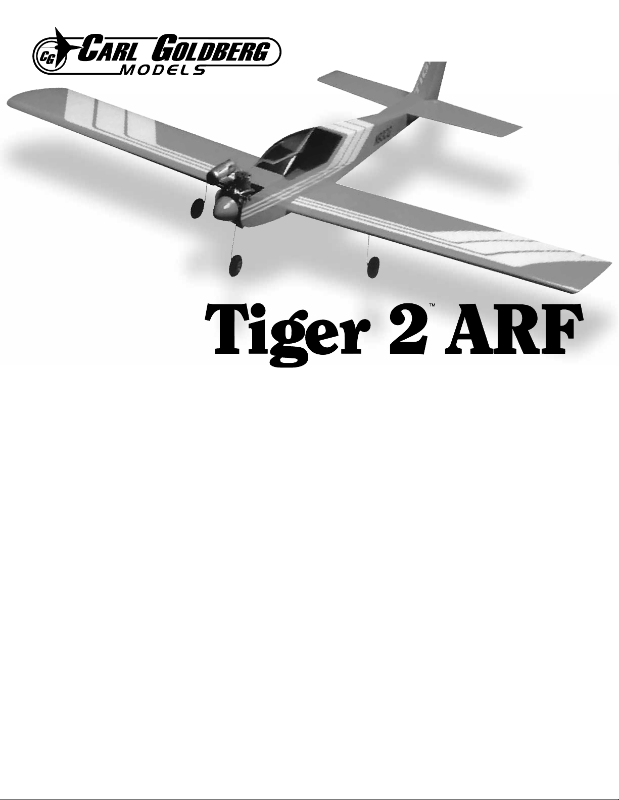
BUILDING STAND
A building stand or cradle comes in handy during the build.
We use the Robart Super Stand II (ROBP1402) for all our
projects in R&D, and it can be seen in pictures throughout
this manual.
BUILD THE WING PANELS
INSTALL THE AILERONS
Do the right wing fi rst so your work matches the photos
the fi rst time through. You can do one wing at a time, or
work on them together.
PREPARATIONS
1. If you have not done so already, remove the major parts
of the kit from the box and inspect for damage. If any parts
are damaged or missing, contact Product Support.
2. Remove the tape and separate all the control surfaces.
Use a covering iron with a covering sock on high heat to
tighten the covering if necessary. Apply pressure over sheeted
areas to thoroughly bond the covering to the wood.
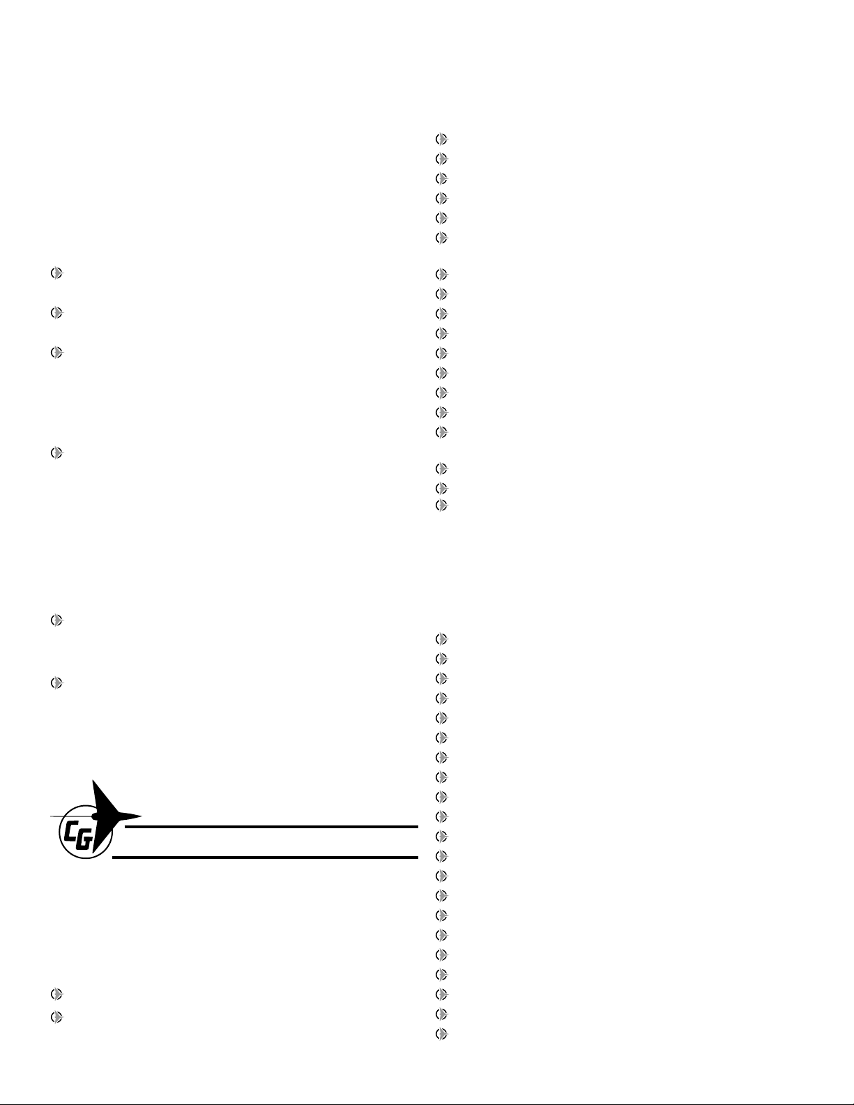
1. Drill a 3/32" [2.4mm] hole 1/2" [13mm] deep into the
center of each hinge slot in the aileron and wing panel. Trim
the covering away from each hinge slot to ensure that the
hinges will be properly glued in place.
2. Test fi t a CA hinge into each of the hinge slots in the
wing panel and aileron. If necessary, enlarge the slots with
a hobby knife. When satisfi ed with the fi t, insert a CA hinge
halfway into each hinge slot in the wing panel. Push a pin
through the middle of each hinge to keep them centered.
4
Page 5
3. Join the aileron to the wing panel and remove
Cut off
unused
arms
Enlarge to
5/64" [2mm]
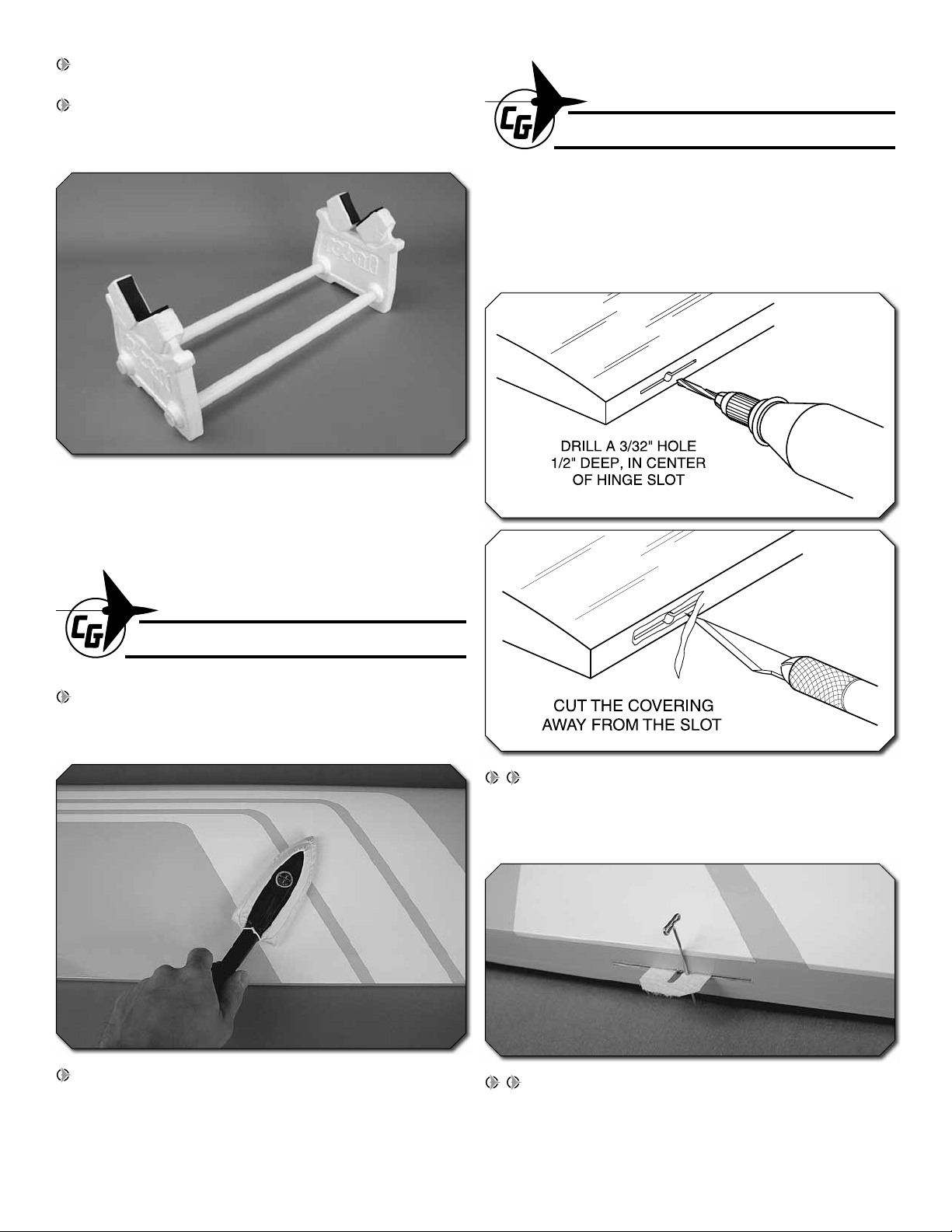
the pins from the hinges. Center the aileron on the wing.
Remove the pins and adjust the aileron so there is a small
gap between the LE of the aileron and the wing. The gap
should be small, just enough to see light through the gap or
to slip a piece of paper through.
INSTALL THE AILERON SERVOS AND PUSHRODS
1. Trim the covering from the aileron servo bay on the
underside of the wing panel.
4. Apply six drops of thin CA to the top and bottom of
each hinge without using accelerator. After the CA glue has
hardened, confi rm that the aileron is secure by pulling on it
and defl ecting it up and down.
5. Repeat steps 1– 4 for the other wing panel.
2. Cut three arms from a four-armed servo arm for the
aileron servo. Enlarge the outer hole of the remaining arm
with a 5/64" [2mm] drill bit.
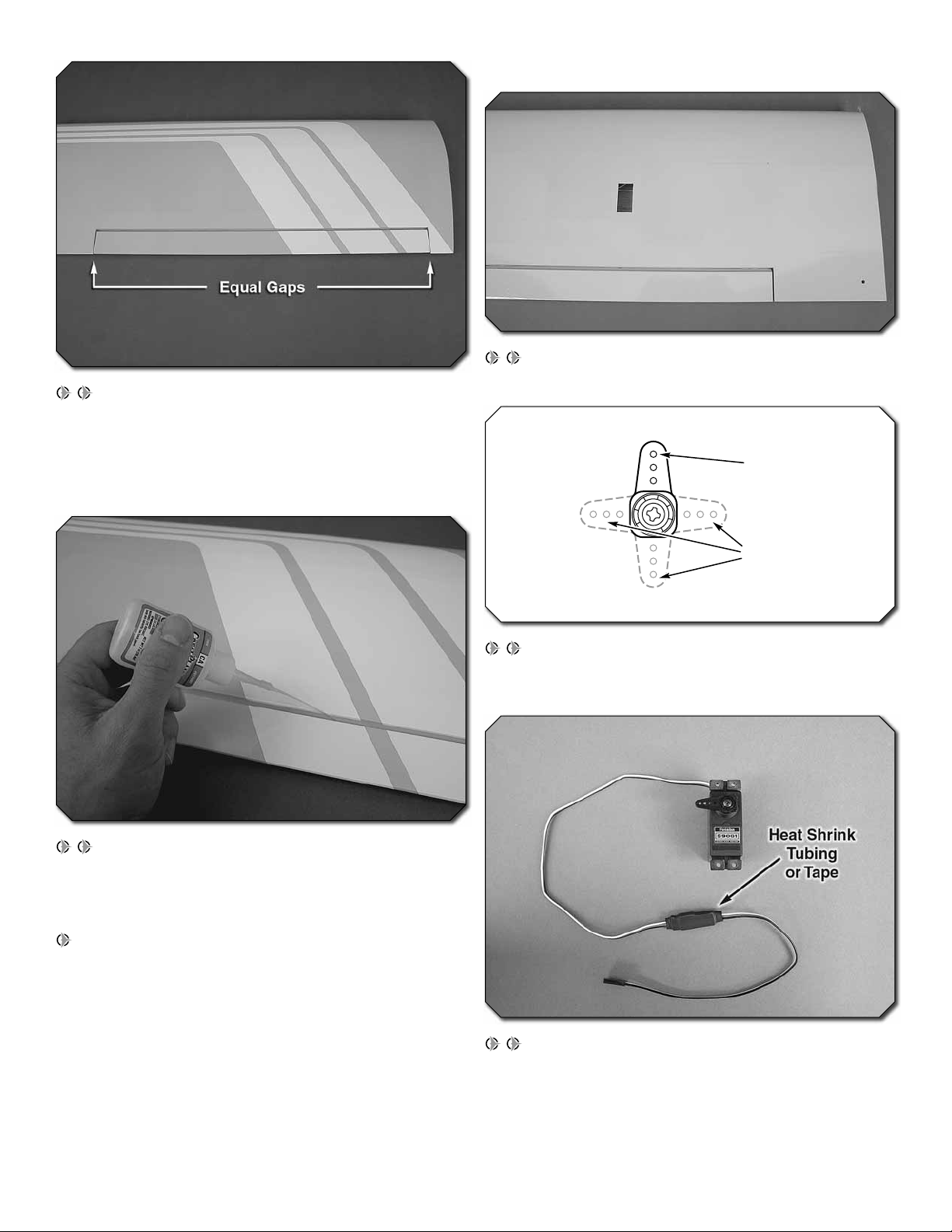
3. Attach a 9" [229mm] servo extension to the aileron
servo and secure the connector using tape, heat shrink tubing
(not included), or a product designed specifi cally for securing
servo lead connections. Center the servo with your radio
system and install the servo arm to the servo perpendicular
to the servo case as shown. Be sure to reinstall the servo
arm screw into the servo.
5
Page 6
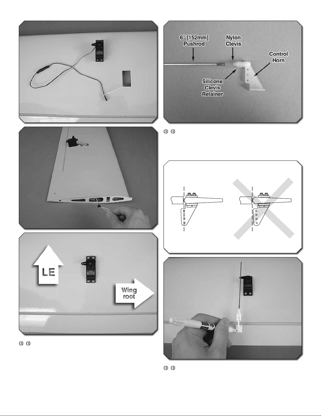
5. Thread a nylon clevis 20 complete turns onto a
Hinge Line Hinge Line
CORRECT INCORRECT
6" [152mm] pushrod. Slide a silicone clevis retainer onto
the clevis and connect the clevis to the outer hole of a
control horn.
4. Use the string taped inside the aileron servo bay to
pull the servo lead through the wing ribs. Fit the servo into
the servo bay with the spline toward the LE of the wing. Drill
1/16" [1.6mm] holes through the mounting tabs on the servo
case into the wing. Thread a servo mounting screw (included
with the servo) into each hole and back it out. Apply a drop
of thin CA to each hole to harden the wood. When the CA
has dried, install the servo using the hardware supplied with
the servo.
6. Position the control horn onto the aileron using the
position of the servo arm as a guide. Align the holes in the
control horns directly over the aileron hinge line and mark
the location of the control horn mounting holes.
6
Page 7
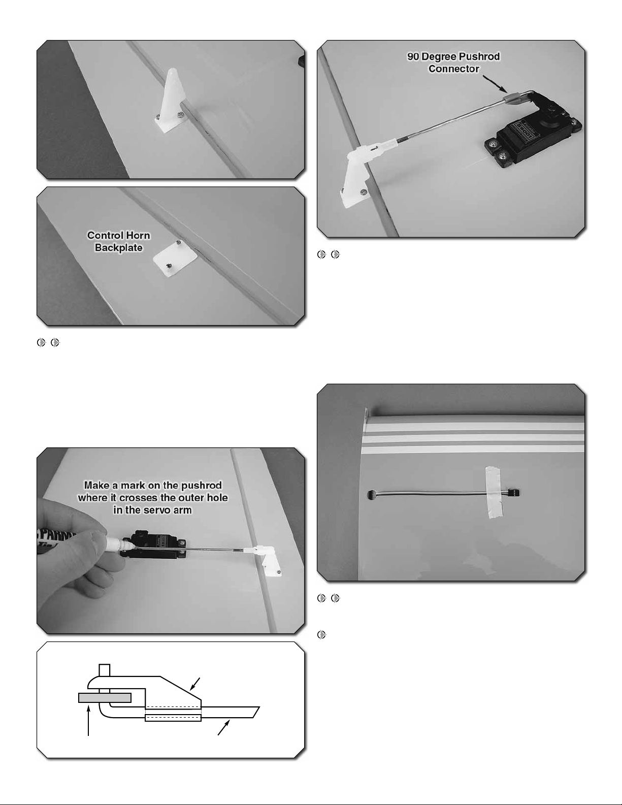
7. Drill 5/64" [2mm] holes at the marks you made
Servo Horn Pushrod Wire
90 Degree
Pushrod
Connector
through the aileron (drill perpendicular to the aileron chord
line). Apply a couple drops of thin CA glue to each hole to
harden the surrounding wood. When the glue has dried,
install the control horn onto the aileron using two 2 x 20mm
machine screws and a control horn backplate. The excess
length of screw protruding beyond the backplate can be
cut off.
8. Use tape or a small clamp to hold the aileron in
the neutral position. Make a mark on the pushrod where it
crosses the outer hole in the servo arm. Make a 90 degree
bend at the mark on the pushrod and cut off the excess
pushrod 1/4" [6mm] beyond the bend. Attach the pushrod to
the servo arm using a 90 degree pushrod connector. Thread
the clevis up or down on the pushrod as necessary to center
the aileron with the servo arm centered. When satisfi ed,
slide the silicone clevis retainer to the end of the clevis to
secure it.
9. Route the servo lead through the hole in the top of
the wing panel and tape it back and out of the way.
10. Repeat steps 1-9 for the other wing panel.
7
Page 8
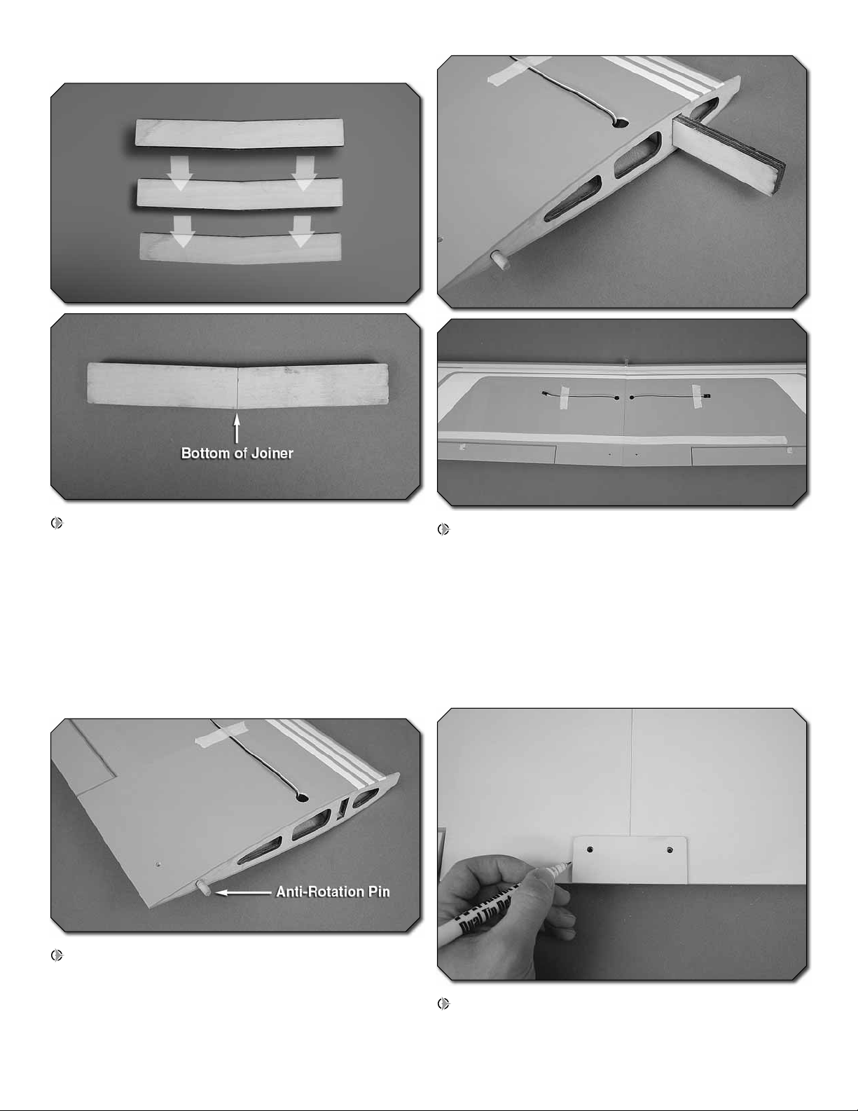
JOIN THE WING PANELS
1. Locate the three plywood wing joiner pieces. Glue the
three pieces together using epoxy. Note that the joiner has
a slight “V” shape that will give the wing a small amount of
dihedral when assembled. The point of the “V” shape is the
bottom of the joiner. Wipe away any excess epoxy with a
cloth dampened with denatured alcohol and use clamps to
hold the pieces together while the epoxy cures. Be sure that
the joiner pieces are glued so the edges are fl ush with each
other. Mark a centerline on the assembled wing joiner. The
centerline is used to confi rm that the wing joiner fi ts halfway
into each wing panel.
3. Use a mixing stick or something similar to coat the
inside of the wing joiner pockets of both wing panels with
30-minute epoxy. Thoroughly coat one half of the wing joiner
with 30-minute epoxy and insert it into the joiner pocket of
one wing panel with the bottom of the “V” shape pointing to
the underside of the wing. Coat the root ribs of both wing
panels and the protruding end of the wing joiner with epoxy.
Slide the wing panels together and use tape to hold them
tight while the epoxy cures. Wipe away any excess epoxy
with denatured alcohol.
2. Read all of step 3 and dry fi t the parts together to ensure
a proper fi t before gluing. Sand the wing joiner or root ribs if
necessary to achieve the correct fi t. The root ribs should join
together tightly with no gaps. When satisfi ed, glue the antirotation pin halfway into the hole of one of the wing panels
as shown.
4. Trim the covering from the holes in the plywood wing
bolt plate as shown. Position the wing bolt plate over the
wing bolt holes on the underside of the wing and use a felttip pen to trace around it.
8
Page 9

5. Use a sharp #11 hobby knife or use the following Expert
Tip to cut the covering 1/16" [1.6mm] inside of the lines you
marked. Use care to cut only in the covering and not into
the wood. Use alcohol to wipe away the lines. Glue the wing
bolt plate in position. If necessary, clean out the wing bolt
holes using a 11/64" [4.4mm] drill bit.
HOW TO CUT COVERING FROM BALSA
Use a soldering iron to cut the covering from the area
beneath the wing bolt plate. The tip of the soldering iron
doesn’t have to be sharp, but a fi ne tip does work best.
Allow the iron to heat fully.
INSTALL THE MAIN LANDING GEAR
1. Slide a 4mm wheel collar onto each main landing
gear wire followed by a wheel and another 4mm wheel
collar. Center the wheels on the landing gear wires and mark
the position of the wheel collars onto the wires. Use a fi le
or rotary tool to grind fl at spots at the marks you made. The
wheel collar screws will tighten against the fl at spots on the
wires. Use four 3x5mm machine screws and thread locking
compound to tighten the wheel collars onto the landing gear
wires. The wheels should rotate freely on the wires. Oil the
axles if necessary.
Use a straightedge to guide the soldering iron at a rate
that will just melt the covering and not burn into the wood.
The hotter the soldering iron, the faster it must travel to
melt a fi ne cut. Peel off the covering.
2. Press the landing gear into the slots on the underside
of the wing.
9
Page 10

3. Position two landing gear straps evenly spaced apart
over each landing gear and mark the location of the strap
holes onto the wing. Drill holes at your marks using a 1/16"
[1.6mm] bit. Thread a 2.5x10mm self-tapping washer head
screw into each hole and back it out. Apply a drop of thin CA
to each hole to harden the wood. When the glue has dried,
install the straps using eight 2.5x10mm self-tapping washer
head screws.
BUILD THE FUSELAGE
INSTALL THE TAIL SURFACES
1. Temporarily install the wing onto the fuselage using two
4x25mm machine screws and two 4mm fl at washers. The
wing will be used to properly align the horizontal stabilizer
onto the fuse.
2. Place the horizontal stab onto the stab saddle as shown.
Center the stab left and right on the fuse (making a center
mark on the stab is helpful) and make the distance between
wing and stab tips equal on both sides. When satisfi ed, use
a felt-tip pen to trace around the saddle where it meets the
underside of the stab. We used a small clamp to hold the
stab in place while we did this.
3. Stand back 5-6 ft [1.5 - 1.8m] and view the model from
behind. Confi rm that the stab and wing are parallel. If not,
sand the fuselage as necessary until they are parallel.
10
Page 11

4. Remove the stab from the fuse and trim the covering
1/16" [1.6mm] inside the lines you drew. Be careful not to cut
into the wood structure beneath the covering. Use denatured
alcohol to wipe away the lines.
5. Coat the stab saddle and the area where you removed
the covering from the stab with 30-minute epoxy. Put the stab
back into place on the saddle and re-center its position. Use
clamps or weights to hold the stab in place while the epoxy
cures. Wipe away any excess epoxy with alcohol.
7. Roughen the ends of the joiner wire with 220 grit
sandpaper and clean them off with alcohol. As you did with
the ailerons, dry fi t the elevator halves onto the stabilizer
using CA hinges and the elevator joiner wire. When satisfi ed
with the fi t, mix up a small batch of epoxy and coat the ends
of the joiner wire. Insert the joiner wire into the elevator halves
and wipe away any excess epoxy. Fit the elevator halves to
the stabilizer with CA hinges and apply 6 drops of thin CA to
both sides of every hinge.
6. Trim the covering away from the elevator joiner wire
slots at the LE of the elevator halves. Confi rm that the joiner
wire fully seats into the slot. Use a hobby knife to enlarge
the slot as necessary. When satisfi ed, test fi t both elevator
halves onto the joiner wire and lay them on a fl at surface.
If both elevator halves do not lay fl at, “tweak”, or bend the
joiner wire until they do. Do not attempt to bend the joiner
wire with it inside the elevators.
8. Trim the covering from the vertical fi n slots in the
fuselage. If necessary, remove the covering from the sides
of the tabs on the vertical fi n.
11
Page 12

horizontal stabilizer. If necessary, use tape to hold the fi n
square while the epoxy cures.
11. Trim the covering from the tail servo pushrod exits on
the left and right sides of the fuselage. Temporarily insert
a 29-1/2" [749mm] pushrod into the elevator outer pushrod
tube that exits the left side of the fuselage. Use the position
of the pushrod to mark the location for the elevator control
horn onto the underside of the elevator.
9. Fit the vertical fi n onto the fuselage and use a felt-tip
pen to trace around it onto the fuselage. Remove the covering
1/16" [1.6mm] inside the lines you drew.
10. Use 30-minute epoxy to glue the fi n into place. Be sure
to put a coating of epoxy along the entire underside length of
the fi n as well as the side of the tabs. Wipe away any excess
epoxy with denatured alcohol. Use a triangle or measure to
confi rm that the vertical fi n is installed perpendicular to the
12. Drill 5/64" [2mm] holes at your marks through the
elevator. Apply a couple drops of thin CA to each hole to
harden the surrounding wood. Install a control horn and
backplate onto the underside of the elevator using two
2x20mm machine screws.
13. Install a control horn onto the right side of the rudder
in the same manner.
12
Page 13

INSTALL THE TAIL SERVOS AND PUSHRODS
1. Cut fi ve arms from a six-armed servo arm and enlarge
the outer hole and inner hole of the remaining arm with a
5/64" [2mm] drill bit. Install a screw-lock pushrod connector
into the inner hole of the servo arm. The plastic screw-lock
pushrod connector retainer may need to be trimmed down to
clear the center of the servo arm. Center the rudder servo with
your radio system and install the servo arm perpendicular to
the servo case as shown. As you did with the aileron servos,
install the rudder servo onto the left side of the servo tray.
clevis. Then insert the pushrod into the rudder outer pushrod
tube and connect the clevis to the third outer hole of the
rudder control horn. As you did with the aileron pushrods,
use tape or a small clamp to hold the rudder in the neutral
position. Make a mark on the pushrod where it crosses the
outer hole in the servo arm. Make a 90 degree bend at the
mark on the pushrod and cut off the excess pushrod 1/4"
[6mm] beyond the bend (removing the pushrod from the
fuselage will make this easier). Attach the pushrod to the
servo arm using a 90 degree pushrod connector. Thread the
clevis up or down on the pushrod as necessary to center the
rudder with the servo arm perpendicular to the servo case.
When satisfi ed, slide the silicone clevis retainer to the end of
the clevis to secure it.
3. Install the elevator servo next to the rudder servo using
the hardware included with the servo. Be sure that the two
servos are not touching each other.
4. Install the elevator pushrod in the same manner as you
installed the rudder pushrod.
2. Thread a nylon clevis 20 complete turns onto a 29-1/2"
[749mm] pushrod. Slide a silicone clevis retainer onto the
13
Page 14

INSTALL THE NOSE GEAR
1. Trim the covering from the nose gear exit at the front
underside of the fuselage.
2. Push a 3mm blind nut into the back of each nose gear
bearing block mounting hole in the fi rewall. Use a 3x12mm
washer head machine screw to draw the blind nuts tight
against the fi rewall.
4. Fit the nylon steering arm between the two nose gear
bearing block halves. Slide the nose gear wire up through
the bearing blocks and the steering arm. Square the axle of
the nose gear wire with the length of the fuselage. Rotate
the steering arm so it is approximately 20 degrees to the
fi rewall as shown. Mark the location of the threaded hole in
the steering arm onto the nose gear wire.
3. Cut apart the nose gear bearing block halves and rotate
them around 180 degrees. Install the bearing block halves
onto the fi rewall using four 3x12mm washer head machine
screws and thread locking compound.
5. Remove the nose gear wire from the bearing blocks. As
you did with the main gear, install two 4mm wheel collars and
a wheel onto the nose gear wire and mark the positions of
the wheel collar screw holes onto the axle. Grind fl ats spots
for the wheel collar screws at your marks as well as for the
14
Page 15

steering arm screw. Install the wheel and wheel collars onto
Top of tank
Vent
Fill and carb lines
the axle using two 3x5mm machine screws and thread locking
compound. Loosely thread a 3x8mm machine screw with
thread locking compound into the steering arm. Install a screwlock pushrod connector into the middle hole in the steering
arm. Reinstall the nose gear wire into the nose gear bearing
blocks and steering arm. Tighten the screw in the steering arm
against the fl at spot you made on the nose gear wire.
1. The fuel tank can be assembled as a two line system
consisting of a vent (pressure) line to the muffl er and a
carb line. Filling and emptying of the tank would need to be
done through the carb line, or an optional fuel fi ll valve (not
included). The tank can also be assembled as a three line
system having a vent line, carb line, and fi ll line. If installing
a fi ll line, puncture the top of the stopper above the sealed
off fuel tube hole. The fi ll and carb lines should extend out
1/2" [13mm] beyond the stopper and the vent line should be
bent upwards. With the tubes installed in the stopper, fi t the
stopper plates loosely in place with the 3 x 20mm phillips
screw to hold the assembly together.
6. Slide the 16-1/4" [413mm] unthreaded pushrod
through the screw-lock pushrod connector on the steering
arm, through the steering outer pushrod tube, and through
the screw-lock pushrod connector on the rudder servo,
positioning the end of the pushrod 1/4" [6mm] beyond the
screw-lock connector on the servo arm. Center the rudder
servo and the nose wheel. Tighten the screws in the screwlock pushrod connectors and cut off the excess pushrod 1/4"
[6mm] beyond the steering arm pushrod connector.
GLOW ENGINE INSTALLATION
The Tiger 2 ARF is designed to be fl own with a .40 –.55
[6.5– 9cc] two-stroke glow engine, .70 [11.5cc] four-stroke
glow engine, or a brushless out-runner motor. If you plan to
install a brushless motor, skip this section as it only contains
information relevant to installing a glow engine.
2. Fit the stopper assembly into the tank with the vent
line pointing toward the top of the tank, but not touching.
The fuel tubing and clunks (fuel pickup) on the carb and fi ll
lines should almost reach the back of the tank but not touch.
The clunks must be able to move freely inside the tank when
assembled. Adjust the length of the fuel tubing accordingly.
When satisfi ed, remove the stopper from the tank. It will need
to be reinstalled after the tank is fi t into the fuselage.
15
Page 16

3. Use a 4x20mm machine screw, engine mount half, and
a 4mm fl at washer to draw the four 4mm blind nuts tight into
the engine mounting holes. Confi rm that the holes you are
using line up with the holes in the engine mount halves (the
unused holes are for a brushless motor mount). Install the
motor mount halves using four 4x20mm machine screws,
four 4mm fl at washers, and thread locking compound.
screw into each hole and back it out. Apply a drop of thin CA
to each hole to harden the wood. Install the hatch cover using
two 2.5x10mm washer head self-tapping screws.
6. Attach a 6" [152mm] piece of fuel tubing to each of the
tubes in the fuel tank stopper.
4. Cut a piece of 1/4" [6mm] foam rubber (not included)
to fi t the fuel tank. Lay the foam rubber inside the fuel tank
compartment. Fit the fuel tank into the compartment and pull
the fuel tank neck through the hole in the fi rewall. Install the
stopper into the tank (be sure the correct side is facing up).
Do not over-tighten the stopper screw.
5. Line the top and sides of the tank with additional foam
rubber. The tank should be held securely by the foam rubber.
Fit the fuel tank hatch cover in place and drill two 1/16" [1.6mm]
pilot holes through the forward end of the hatch cover and into
the fi rewall. Thread a 2.5x10mm washer head self-tapping
7. Position your engine 4-1/4" [108mm] from the fi rewall.
Use a Great Planes Dead Center Hole Locator to mark the
location of the engine mount holes onto the engine mount
halves. If necessary, carve away any portion of the fuselage
that interferes with the needle valve or exhaust. Drill 1/8"
[3.2mm] holes through the marks you made.
8. Attach the engine to the engine mount halves using four
3x25mm machine screws, eight 3mm fl at washers, and four
16
Page 17

3mm nylon insert lock nuts. Use a lock nut and washer on
the underside of the engine mount halves on each screw.
9. Mount the throttle servo onto the servo tray. Make sure
that it is not touching the elevator servo. Use your radio
system to center the servo.
into the second outer hole of the servo arm. Thread a nylon
clevis 20 complete turns onto the remaining 16-1/4" [413mm]
pushrod. Slide a silicone clevis retainer onto the base of the
clevis. Slide the pushrod through the throttle outer pushrod
tube pre-installed in the fuse. Fit the aft end through the
screw-lock pushrod connector installed on the throttle servo.
Make any necessary bends to the forward end of the pushrod
and connect the clevis to the throttle arm on the carburetor.
Adjust the pushrod in the screw-lock connector so the servo
properly opens and closes the carburetor. When satisfi ed,
tighten the screw-lock connector screw, slide the silicone
clevis retainer to the end of the clevis, and cut the excess
pushrod 1/4" [6mm] behind the screw-lock connector.
10. Cut fi ve arms from a six-armed servo arm and
enlarge the second outer hole of the remaining arm with a
5/64" [2mm] drill bit. Install a screw-lock pushrod connector
11. Make any fi nal connections to the engine such as the
pressure line to the muffl er, carb line, etc. If you assembled
the fuel tank with a fi ll line, cut the fi ll line to length and plug
the line with a fuel line plug (not included).
12. Install the bottom hatch cover with two 2.5x10mm
washer head self-tapping screws. Be sure to harden the
wood surrounding the holes with thin CA.
17
Page 18

BRUSHLESS MOTOR INSTALLATION
If you have installed a glow engine, skip this section as it only
contains information relevant to installing a brushless motor.
Be sure to read and understand the instructions that
come with the ESC and motor before attempting to
operate the system.
1. Attach the out-runner motor to the brushless motor
mount using the included 3 x 8mm machine screws and thread
locking compound. If you haven’t done so yet, install the prop
adapter to the motor case with the hardware included with
the motor and thread locking compound. Loosen the screws
that hold the two motor mount halves together and set the
distance from the back side of the mount to the front of the
prop washer to be 4-5/8" [117mm]. Retighten the screws
using thread locking compound.
3. Apply a thin coating of epoxy where you plan to mount
the ESC. This will improve the adhesion of the doublesided foam mounting tape (not included). Let the epoxy
cure undisturbed. Connect the ESC to the motor. This is a
good time to confi rm the correct rotation of the motor by
temporarily connecting the battery and radio system to the
ESC and powering the motor (without prop). If the motor
rotates the wrong direction, simply disconnect any two of the
three motor leads and swap their position. Use double-sided
foam mounting tape to secure the ESC in place.
2. Locate the pre-drilled holes in the fi rewall that match up
with the Great Planes medium motor mount. Use a 4x20mm
machine screw and a 4mm fl at washer to draw four 4mm
blind nuts tight into the holes. Attach the motor mount to the
fi rewall using four 4x20mm machine screws, four 4mm fl at
washers, and thread locking compound.
4. Apply a piece of self-adhesive hook and loop material
inside the battery compartment (don’t forget a coat of epoxy
to improve adhesion). Make a strap from the included hook
and loop strap material to fi t around your battery packs by
overlapping the mating ends by approximately 1" [25mm]. Fit
the strap ends through the slots in the battery tray. Cut the
strap to length as needed.
18
Page 19

5. Test fi t your battery packs in the battery compartment.
They can be secured together with additional self-adhesive
hook and loop material, but the packs may need to be
inserted into the compartment one at a time.
FINISH THE MODEL
1. Pre-cut slots are provided on both sides of the fuselage
for an on/off switch. The slots may need to be enlarged
depending on what brand switch harness you are using.
6. Fit the ESC hatch cover in place and drill through
the pre-cut mounting holes into the hardwood rail using a
1/16" [1.6mm] drill bit. Thread a 2.5x10mm washer head
self-tapping screw into each hole and back it out. Apply a
drop of thin CA to each hole to harden the wood. Install the
hatch cover using two 2.5x10mm washer head self-tapping
screws. Trim the covering from the cool air exit slots in the
hatch cover.
7. Mount the battery hatch cover using two 2.5x10mm
washer head self-tapping screws.
2. Wrap your receiver and receiver battery in foam rubber
(not included). Connect the battery to the switch and the
servos and switch lead to the receiver (be sure to secure the
connection between the battery and the switch using tape or
heat shrink tubing). Stuff the components into the fuselage
and use scrap sticks of wood to hold them securely in place.
It is recommended to only tack glue the sticks in place at this
time as the components may need to be shifted forward or
aft when balancing the plane. When the exact position of the
radio components is confi rmed, be sure to thoroughly glue
the sticks in place.
19
Page 20

2. Be certain the model is clean and free from oily fi ngerprints
OKAY
and dust. Prepare a dishpan or small bucket with a mixture
of liquid dish soap and warm water—about one teaspoon of
soap per gallon of water. Submerse the decal in the soap and
water and peel off the paper backing. Note: Even though the
decals have a “sticky-back” and are not the water transfer
type, submersing them in soap & water allows accurate
positioning and reduces air bubbles underneath.
3. Position decal on the model where desired. Holding
the decal down, use a paper towel to wipe most of the
water away.
3. Apply the instrument panel decal (see Apply the
Decals section). Use canopy glue to glue the canopy in
place as shown. Tape the canopy down and allow the glue
to dry overnight. The canopy can also be screwed into place
(additional screws not included).
4. Install the spinner backplate, propeller, prop washer,
prop nut, and spinner cone onto the engine crankshaft. The
spinner backplate (and propeller) may need to be drilled or
reamed larger to match the crankshaft diameter. Be sure to
balance your prop!
4. Use a piece of soft balsa or something similar to squeegee
remaining water from under the decal. Apply the rest of the
decals the same way.
GET THE MODEL READY TO FLY
INSTALL AND OPERATE THE MOTOR BATTERY
(BRUSHLESS ONLY)
IMPORTANT: If using multiple battery packs that are connected
with an adapter, never charge the batteries together through
the adapter. Always charge each battery pack separately.
Charge the batteries, then read the following precautions on
how to connect multiple packs for fl ying the model:
BATTERY PRECAUTIONS:
There are two ways to connect multiple battery packs: In
Series and in Parallel.
5. This completes the assembly of the Tiger 2 ARF!
APPLY THE DECALS
1. Use scissors or a sharp hobby knife to cut the decals from
the sheet.
❏ 1. Connecting batteries in “Series” means to connect
the +’s to the –’s and the –’s to the +’s. This combines the
batteries’ Voltages, but the capacity remains the same.
20
Page 21

OKAY
These are three 11.1V, 3200mAh batteries. When joined
in Series, the result will be a 33.3V, 3200mAh battery.
❏ 2. Connecting batteries in “Parallel” means to connect
NO!!!
NO!!!
NO!!!
FULL
THROTTLE
RUDDER
MOVES
RIGHT
ELEVATOR
MOVES DOWN
RIGHT AILERON
MOVES UP
LEFT AILERON
MOVES DOWN
/
4-CHANNEL RADIO SETUP
(STANDARD MODE 2)
the +’s to the +’s and the -’s to the -’s. This combines the
batteries’ capacities, but the Voltage remains the same.
LITHIUM BATTERY HANDLING & USAGE
WARNING!! Read the entire instruction sheet included with
the battery. Failure to follow all instructions could cause
permanent damage to the battery and its surroundings, and
cause bodily harm!
• ONLY use a LiPo approved charger.
• NEVER charge in excess of 4.20V per cell.
• ONLY charge through the “charge” lead. NEVER
charge through the “discharge” lead.
• NEVER charge at currents greater than 1C.
• ALWAYS set charger’s output volts to match
battery volts.
• ALWAYS charge in a fi reproof location.
• NEVER trickle charge.
• NEVER allow battery temperature to exceed
150° F (65° C).
• NEVER disassemble or modify pack wiring in any
way or puncture cells.
• NEVER discharge below 3.0V per cell
• NEVER place on combustible materials or leave
unattended during charge or discharge.
• ALWAYS KEEP OUT OF REACH OF CHILDREN.
CHECK THE CONTROL DIRECTIONS
NEVER connect battery packs with different Voltages in
Parallel–only combine in Series. Otherwise, the batteries
will try to “equalize” with the larger one trying to “charge” the
smaller one, thus causing heat and likely a fi re.
Also NEVER connect battery packs with different capacities
in Series or in Parallel.
1. Turn on the transmitter and receiver and center the
trims. If necessary, remove the servo arms from the servos
and reposition them so they are centered. Reinstall the
screws that hold on the servo arms.
2. With the transmitter and receiver still on, check
all the control surfaces to see if they are centered. If
necessary, adjust the clevises on the pushrods to center
the control surfaces.
3. Make certain that the control surfaces and the throttle
respond in the correct direction as shown in the diagram.
If any of the controls respond in the wrong direction, use
21
Page 22

the servo reversing in the transmitter to reverse the servos
These are the recommended control surface throws:
ELEVATOR
HIGH RATE LOW RATE
5/16"
[8mm]
11 deg
Up
5/16"
[8mm]
11 deg
Down
3/16"
[4.8mm]
7 deg
Up
3/16"
[4.8mm]
7 deg
Down
RUDDER
7/8"
[22mm]
13 deg
Right
7/8"
[22mm]
13 deg
Left
5/8"
[16mm]
9 deg
Right
5/8"
[16mm]
9 deg
Left
AILERONS
7/16"
[11mm]
14 deg
Up
7/16"
[11mm]
14 deg
Down
5/16"
[8mm]
10 deg
Up
5/16"
[8mm]
10 deg
Down
connected to those controls. Be certain the control surfaces
have remained centered. Adjust if necessary.
SET THE CONTROL THROWS
Use a Great Planes AccuThrow™ (or a ruler) to accurately
measure and set the control throw of each control surface
as indicated in the chart that follows. If your radio does not
have dual rates, we recommend setting the throws at the
low rate setting.
IMPORTANT: The Tiger 2 ARF has been extensively
fl own and tested to arrive at the throws at which it fl ies
best. Flying your model at these throws will provide you
with the greatest chance for successful fi rst fl ights. If,
after you have become accustomed to the way the Tiger
2 fl ies, you would like to change the throws to suit your
taste, that is fi ne. However, too much control throw could
make the model diffi cult to control, so remember, “more
is not always better.”
NOTE: The throws are measured at the widest part of
the elevators, rudder and ailerons. If you are using a ruler
to set your control surface throws, the defl ection distance
is measured as the height from the center trailing edge of
the control surface when moved from the neutral position as
shown in the sketch. Defl ection in degrees is also provided
for an alternative measuring method.
BALANCE THE MODEL (C.G.)
More than any other factor, the C.G. (balance point)
can have the greatest effect on how a model fl ies, and
may determine whether or not your fi rst fl ight will be
successful. If you value this model and wish to enjoy it for
many fl ights, DO NOT OVERLOOK THIS IMPORTANT
PROCEDURE. A model that is not properly balanced
will be unstable and possibly unfl yable.
At this stage the model should be in ready-to-fl y condition
with all of the systems in place including the engine or
brushless motor, landing gear, and the radio system (and
battery pack if applicable).
1. Use a felt-tip pen or 1/8" [3mm]-wide tape to accurately
mark the C.G. on the top of the wing on both sides of the
fuselage. The C.G. is located 3-7/8" [98mm] back from the
leading edge of the wing.
This is where your model should balance for the fi rst
fl ights. Later, you may wish to experiment by shifting
the C.G. up to 3/8" [9.5mm] forward or 3/8" [9.5mm]
back to change the fl ying characteristics. Moving the
C.G. forward may improve the smoothness and stability,
but the model may then require more speed for takeoff
and make it more diffi cult to slow for landing. Moving
the C.G. aft makes the model more maneuverable, but
could also cause it to become too diffi cult to control. In
any case, start at the recommended balance point
and do not at any time balance the model outside the
specifi ed range.
22
Page 23

2. With the wing attached to the fuselage, all parts of the
model installed (ready to fl y) and an empty fuel tank, place
the model upside-down on a Great Planes CG Machine,™ or
lift it upside-down at the balance point you marked.
3. If the tail drops, the model is “tail heavy” and the battery
pack and/or receiver must be shifted forward or weight must
be added to the nose to balance. If the nose drops, the model
is “nose heavy” and the battery pack and/or receiver must be
shifted aft or weight must be added to the tail to balance. If
possible, relocate the battery pack and receiver to minimize or
eliminate any additional ballast required. If additional weight is
required, nose weight may be easily added by using a “spinner
weight” (GPMQ4645 for the 1 oz. [28g] weight, or GPMQ4646
for the 2 oz. [57g] weight). If spinner weight is not practical or
is not enough, use Great Planes (GPMQ4485) “stick-on” lead.
A good place to add stick-on nose weight is to the fi rewall
(don’t attach weight to the cowl—it is not intended to support
weight). Begin by placing incrementally increasing amounts
of weight on the bottom of the fuse over the fi rewall until the
model balances. Once you have determined the amount of
weight required, it can be permanently attached. If required,
tail weight may be added by cutting open the bottom of the
fuse and gluing it permanently inside.
Note: Do not rely upon the adhesive on the back of the lead
weight to permanently hold it in place. Over time, fuel and
exhaust residue may soften the adhesive and cause the
weight to fall off. Use #2 sheet metal screws, RTV silicone or
epoxy to permanently hold the weight in place.
4. IMPORTANT: If you found it necessary to add any
weight, recheck the C.G. after the weight has been installed.
BALANCE THE MODEL LATERALLY
1. With the wing level, have an assistant help you lift the
model by the engine propeller shaft and the bottom of the
fuse under the TE of the fi n. Do this several times.
FLYING
The Tiger 2 ARF is a great-fl ying model that fl ies smoothly
and predictably. The Tiger 2 does not, however, possess the
self-recovery characteristics of a primary R/C trainer and
should be fl own only by experienced R/C pilots.
FUEL MIXTURE ADJUSTMENTS
A fully cowled engine may run at a higher temperature than
an un-cowled engine. For this reason, the fuel mixture should
be richened so the engine runs at about 200 rpm below
peak speed. By running the engine slightly rich, you will help
prevent dead-stick landings caused by overheating.
TAKEOFF
If you have dual rates on your transmitter, set the switches
to “high rate” for takeoff, especially when taking off in
a crosswind. Although this model has good low-speed
characteristics, you should always build up as much speed
as your runway will permit before lifting off, as this will give
you a safety margin in case of a “fl ame-out.” When you fi rst
advance the throttle the plane will usually turn left slightly.
Correct by applying suffi cient right rudder to hold it straight
down the runway. When the plane has suffi cient fl ying speed,
lift off by smoothly applying up elevator (don’t pull it hard into
a steep climb!), and climb out gradually.
FLIGHT
We recommend that you take it easy with your Tiger 2 ARF
for the fi rst several fl ights, gradually “getting acquainted”
with this realistic model as your engine gets fully brokenin. Add and practice one maneuver at a time, learning how
she behaves in each. For ultra-smooth fl ying and normal
maneuvers, we recommend using the “low rate” settings
as listed on page 22. Well before it’s time to land, fl y your
Tiger 2 ARF to a safe altitude. Cut the throttle to an idle
and check out the model’s low-speed characteristics. Do
this several times to become familiar with how the Tiger
2 ARF handles stalls. This also helps you learn what to
expect when landing.
LANDING
When it’s time to land, fl y a normal landing pattern and
approach. For your fi rst landings, plan to approach slightly
faster than stall speed and fl are a few inches off the runway
onto the main wheels.
2. If one wing always drops when you lift the model, it
means that side is heavy. Balance the airplane by adding
weight to the other wing tip. An airplane that has been
laterally balanced will track better in loops and other
maneuvers.
23
Page 24

www.carlgoldbergproducts.com
© Copyright 2009 GBGA1066Mnl
24
 Loading...