

Page 1
™
Wingspan: 79 in [2005mm]
Wing Area: 674 sq in [43.5 dm2]
Weight: 2.0–2.25 lb [910–1020g]
Wing Loading: 7–8 oz/sq ft [21–24 g/dm2]
Length: 41 in [1040mm]
Radio: 2-channel minimum with 2 servos and standard size receiver
™
WARRANTY
Great Planes guarantees this kit to be free from defects in both material and workmanship at the date of purchase.
This warranty does not cover any component parts damaged by use or modifi cation. In no case shall Great Planes’
liability exceed the original cost of the purchased kit. Further, Great Planes reserves the right to change or
modify this warranty without notice.
In that Great Planes has no control over the fi nal assembly or material used for fi nal assembly, no liability shall be
assumed nor accepted for any damage resulting from the use by the user of the fi nal user-assembled product. By
the act of using the user-assembled product, the user accepts all resulting liability.
If the buyer is not prepared to accept the liability associated with the use of this product, the buyer is
advised to return this kit immediately in new and unused condition to the place of purchase.
To make a warranty claim Hobby Services
send the defective part 3002 N. Apollo Dr., Suite 1
or item to Hobby Services Champaign, IL 61822 USA
at this address: (217) 398-8970 Ext. 5
Include a letter stating your name, return shipping address, as much contact information as possible (daytime
telephone number, fax number, e-mail address), a detailed description of the problem and a photocopy of the
purchase receipt. Upon receipt of the package, the problem will be evaluated as quickly as possible.
READ THROUGH THIS MANUAL BEFORE STARTING CONSTRUCTION. IT CONTAINS IMPORTANT INSTRUCTIONS
AND WARNINGS CONCERNING THE ASSEMBLY AND USE OF THIS MODEL.
Page 2
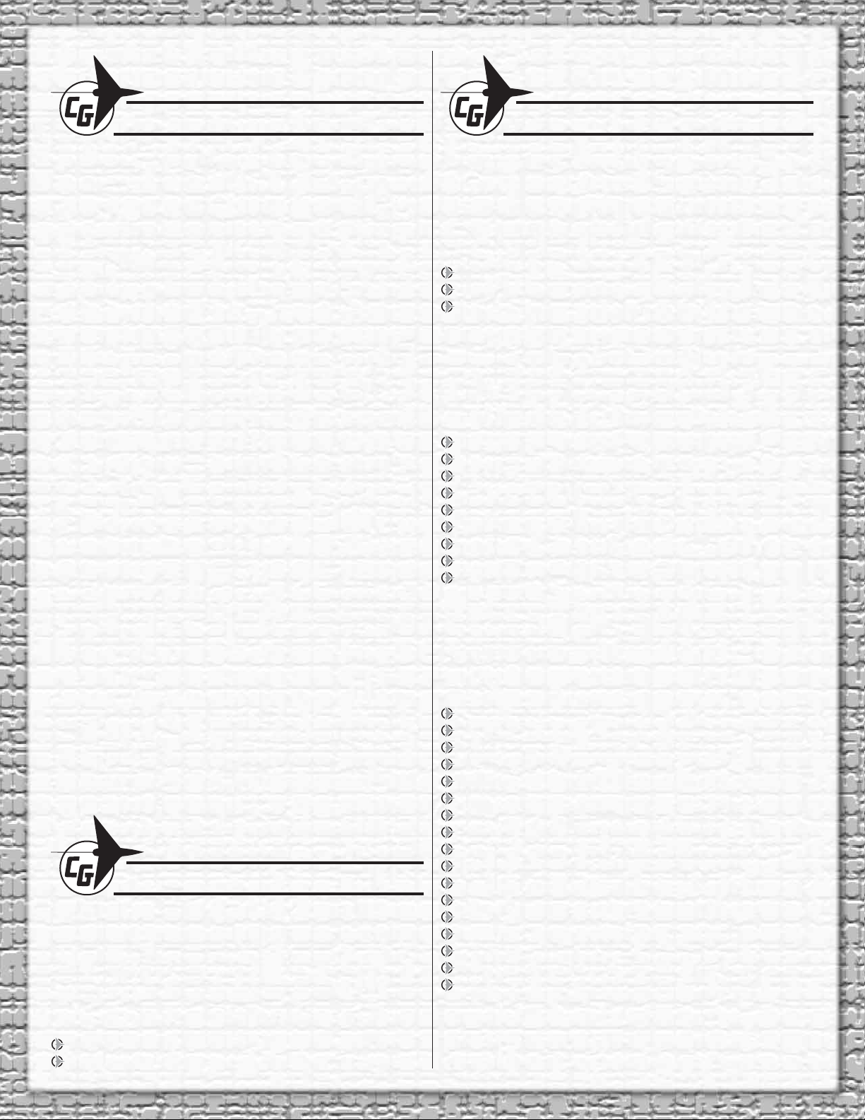
TABLE OF CONTENTS
ADDITIONAL ITEMS REQUIRED
THINGS TO CONSIDER . . . . . . . . . . . . . . . . . . . . . . . . . . 2
ADDITIONAL ITEMS REQUIRED . . . . . . . . . . . . . . . . . . . 2
Required Hardware and Accessories . . . . . . . . . . . . . 2
Adhesives and Building Supplies. . . . . . . . . . . . . . . . . 2
Optional Supplies and Tools. . . . . . . . . . . . . . . . . . . . . 2
Building Stand . . . . . . . . . . . . . . . . . . . . . . . . . . . . . . . 3
PREPARATIONS . . . . . . . . . . . . . . . . . . . . . . . . . . . . . . . . 3
JOIN THE WING PANELS . . . . . . . . . . . . . . . . . . . . . . . . . 3
INSTALL THE TAIL SECTION . . . . . . . . . . . . . . . . . . . . . . 4
INSTALL THE SERVOS AND PUSHRODS . . . . . . . . . . . . 6
INSTALL THE RECEIVER AND BATTERY . . . . . . . . . . . . 9
FINISH THE MODEL . . . . . . . . . . . . . . . . . . . . . . . . . . . . 10
APPLY THE DECALS . . . . . . . . . . . . . . . . . . . . . . . . . . . 10
GET THE MODEL READY TO FLY . . . . . . . . . . . . . . . . . 10
Check the Control Directions . . . . . . . . . . . . . . . . . . . 10
Set the Control Throws. . . . . . . . . . . . . . . . . . . . . . . . 11
Balance the Model (C.G.). . . . . . . . . . . . . . . . . . . . . . 12
Balance the Model Laterally. . . . . . . . . . . . . . . . . . . . 12
FLYING. . . . . . . . . . . . . . . . . . . . . . . . . . . . . . . . . . . . . . . 12
Trim Flights. . . . . . . . . . . . . . . . . . . . . . . . . . . . . . . . . 13
Hi-Start Launch . . . . . . . . . . . . . . . . . . . . . . . . . . . . . 13
First Flights . . . . . . . . . . . . . . . . . . . . . . . . . . . . . . . . 13
THERMAL FLYING . . . . . . . . . . . . . . . . . . . . . . . . . . . . . 14
Facts About Thermals . . . . . . . . . . . . . . . . . . . . . . . . 14
Thermal Soaring . . . . . . . . . . . . . . . . . . . . . . . . . . . . 14
POINTERS FOR CONTEST FLYING. . . . . . . . . . . . . . . . 15
SLOPE SOARING . . . . . . . . . . . . . . . . . . . . . . . . . . . . . . 15
Slope Landings . . . . . . . . . . . . . . . . . . . . . . . . . . . . . 15
Ballasting . . . . . . . . . . . . . . . . . . . . . . . . . . . . . . . . . . 15
The Gentle Lady ARF sailplane was designed to be a gentle
trainer for the beginning modeler, yet to possess competition
capability in the hands of the experienced glider pilot. The
Gentle Lady is very effi cient and reacts quickly to rising air
(called lift, or thermals). To stay in a thermal, the Gentle Lady
can circle very tightly without falling off. The model has good
penetration into the wind and can “cruise” when desired.
THINGS TO CONSIDER
The Gentle Lady ARF requires a minimum 2-channel radio
system with two 44 oz.-in. [3.2 kg-cm] minimum standard
servos. A charge jack receptacle is optional, but is useful for
quickly checking and recharging the receiver pack without
removing the radio hatch. Recommended part numbers for
the radio components are provided below:
REQUIRED HARDWARE AND ACCESSORIES
This is the list of hardware and accessories required to
fi nish the Gentle Lady ARF. Order numbers are provided
in parentheses:
R/C foam rubber 1/4" [6mm] (HCAQ1000)
Dynafl ite™ Up-Start 2M (DYFP8305)
Hobbico® #64 rubber bands (HCAQ2020)
ADHESIVES AND BUILDING SUPPLIES
This is the list of Adhesives and Building Supplies that are
required to fi nish the Gentle Lady ARF:
1/2 oz. [15g] Thin Pro™ CA (GPMR6001)
Pro 30-minute epoxy (GPMR6047)
Denatured alcohol (for epoxy clean up)
Drill bits: 1/16” [1.6mm], 5/64” [2mm]
#1 Hobby knife (HCAR0105)
#11 blades (5-pack, HCAR0211)
Top Flite® MonoKote® sealing iron (TOPR2100)
Top Flite Hot Sock™ iron cover (TOPR2175)
Panel Line Pen (TOPQ2510)
OPTIONAL SUPPLIES AND TOOLS
Here is a list of optional tools that will help you build the
Gentle Lady ARF:
1/2 oz. [15g] Thick Pro CA– (GPMR6013)
2 oz. [57g] spray CA activator (GPMR6035)
4 oz. [113g] aerosol CA activator (GPMR6034)
CA applicator tips (HCAR3780)
CA debonder (GPMR6039)
Pro 6-minute epoxy (GPMR6045)
Epoxy brushes (GPMR8060)
Mixing sticks (GPMR8055)
Mixing cups (GPMR8056)
Pliers with wire cutter (HCAR0630)
Servo horn drill (HCAR0698)
CG Machine™ (GPMR2400)
Hobbico® fl exible 18" ruler stainless steel (HCAR0460)
Top Flite MonoKote trim seal iron (TOPR2200)
Top Flite MonoKote heat gun (TOPR2000)
Hobbico pin vise 1/16 collet w/6 Bits (HCAR0696)
Great Planes® Clevis Installation Tool (GPMR8030)
Futaba® S3004 Servo Standard (FUTM0004)
Ernst Charge Receptacle Futaba J FM (ERNM3001)
2
Page 3
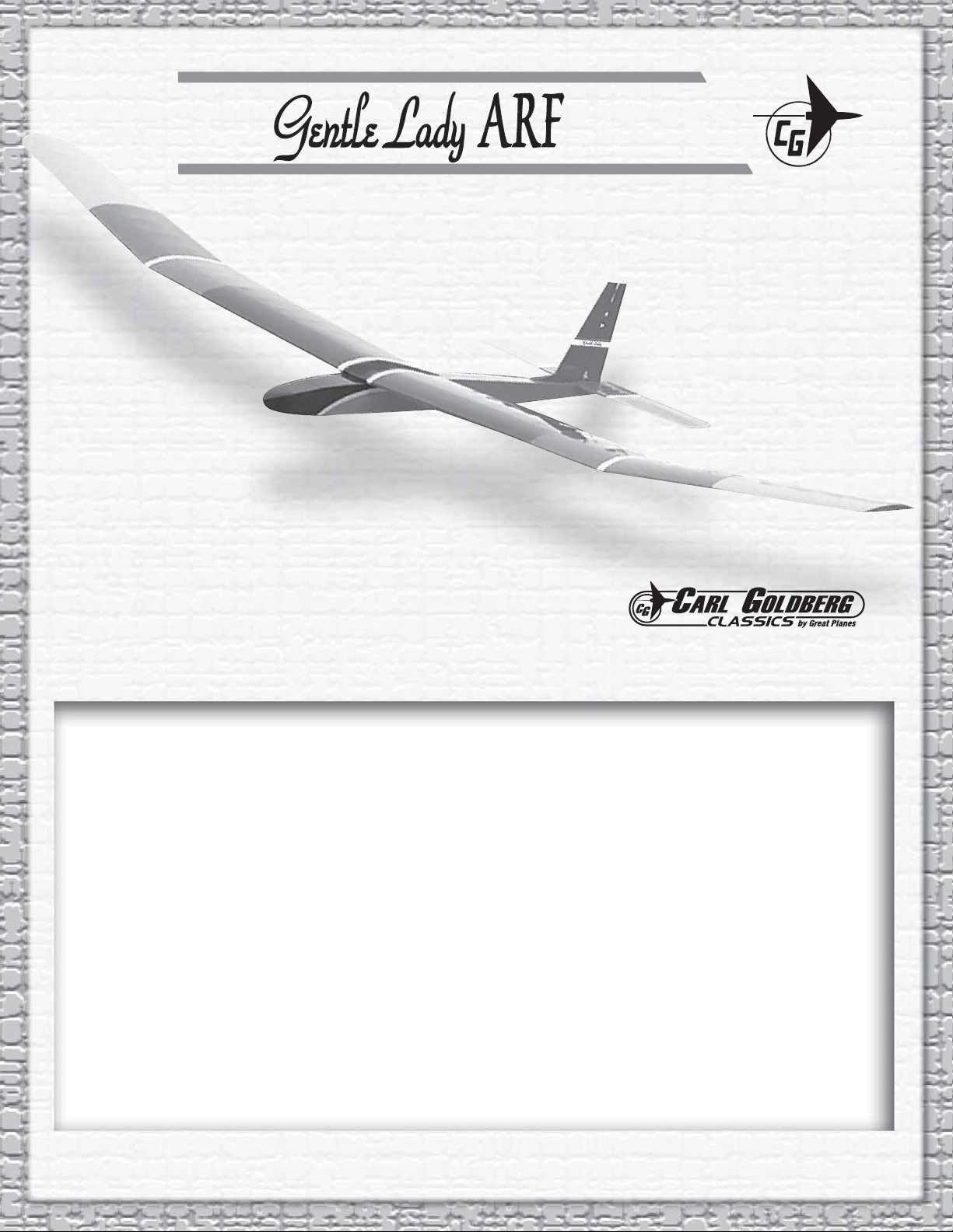
BUILDING STAND
JOIN THE WING PANELS
A building stand or cradle comes in handy during the build.
We use the Robart Super Stand II (ROBP1402) for all our
projects in R&D, and it can be seen in pictures throughout
this manual.
PREPARATIONS
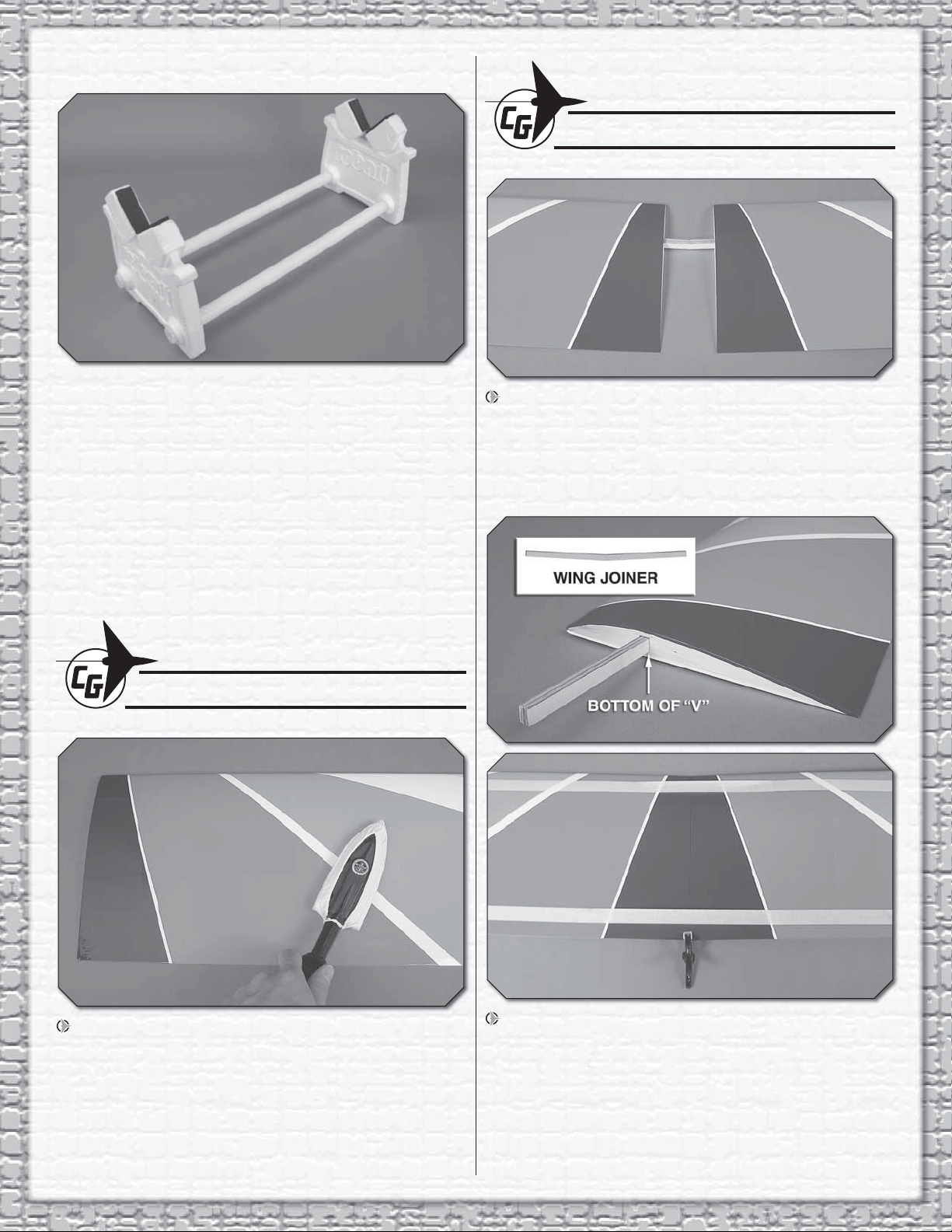
1. Test fi t the wing joiner into the wing panels. The point
of the “V” shaped joiner should point to the bottom of the
wing panels. Sand the wing joiner or root ribs if necessary
to achieve the correct fi t. The root ribs should join together
tightly with no gaps and the joiner should be just slightly
loose in the joiner pockets to allow room for epoxy.
Remove the tape and separate all the control surfaces.
Use a covering iron with a covering sock on high heat to
tighten the covering if necessary. Apply pressure over sheeted
areas to thoroughly bond the covering to the wood.
2. Use a mixing stick or something similar to coat the
inside of the wing joiner pockets of both wing panels with
30-minute epoxy. Thoroughly coat one half of the wing joiner
with 30-minute epoxy and insert it into the joiner pocket of
one wing panel with the bottom of the “V” shape pointing to
the underside of the wing. Coat the root ribs of both wing
panels and the protruding end of the wing joiner with epoxy.
Slide the wing panels together and use tape to hold them
tight while the epoxy cures.
3
Page 4
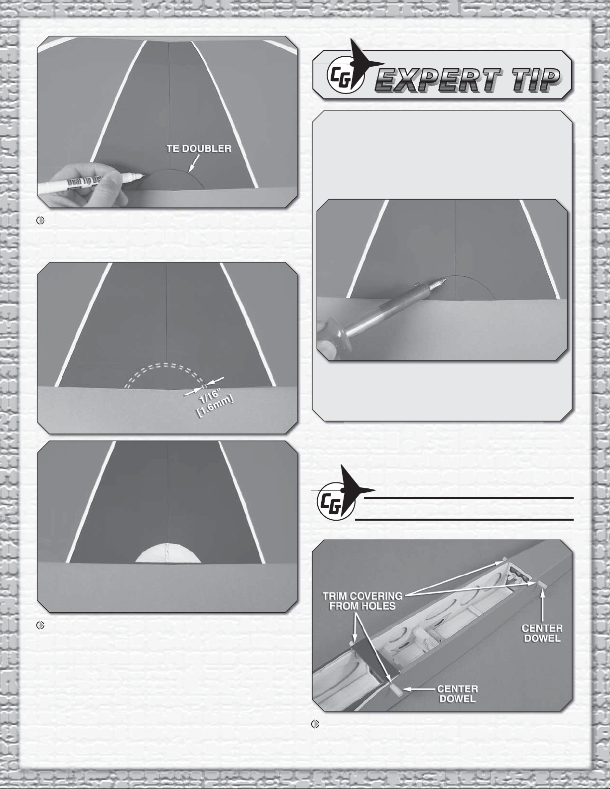
3. Center the plywood TE doubler along the TE of the
wing as shown. Use a felt-tip pen to trace around the doubler
onto the wing.
HOW TO CUT COVERING FROM BALSA
Use a soldering iron to cut the covering from the area
beneath the wing bolt plate. The tip of the soldering iron
doesn’t have to be sharp, but a fi ne tip does work best.
Allow the iron to heat fully.
Guide the soldering iron at a rate that will just melt the
covering and not burn into the wood. The hotter the
soldering iron, the faster it must travel to melt a fi ne cut.
Peel off the covering.
4. Use a sharp #11 hobby knife or use the following Expert
Tip to cut the covering 1/16" [1.6mm] inside of the lines you
marked. Use care to cut only the covering and not into the
wood. Use alcohol to wipe away the lines. Glue the doubler
in position with CA or epoxy.
INSTALL THE TAIL SECTION
1. Trim the covering from the rubber band dowel holes in
the sides of the fuselage. Center the dowels in the holes as
shown and glue them in place with CA or epoxy.
4
Page 5
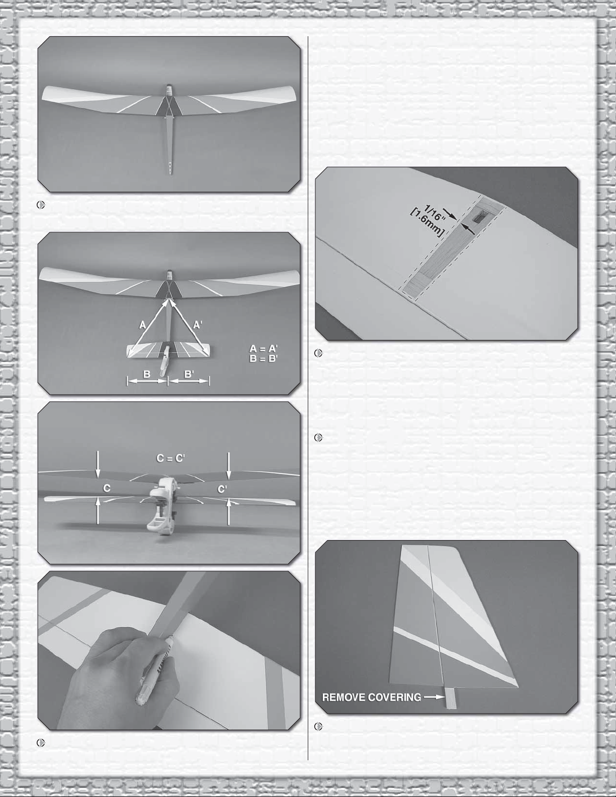
2. Center the wing on the fuselage and secure it using
two crisscrossed rubberbands as shown.
a center mark on the stab is helpful) and make the distance
between the fuse center and stab tips equal on both sides.
Stand back 5-6 ft [1.5 - 1.8m] and view the model from
behind. Confi rm that the stab and wing are parallel. If not,
sand the fuselage as necessary until they are parallel. When
satisfi ed, use a felt-tip pen to trace around the saddle where
it meets the underside of the stab. We used a small clamp to
hold the stab in place while we did this.
4. Remove the stab from the fuse and trim the covering
1/16" [1.6mm] inside the lines you drew. Be careful not to cut
into the wood structure beneath the covering. Use denatured
alcohol to wipe away the lines.
5. Coat the stab saddle on the fuselage and the area
where you removed the covering from the stab with 30-minute
epoxy. Put the stab back into place on the saddle and recenter its position. Use clamps or weights to hold the stab in
place while the epoxy cures. Wipe away any excess epoxy
with alcohol.
3. Place the horizontal stabilizer onto the stab saddle
as shown. Center the stab left and right on the fuse (making
6. Trim the covering from the vertical fi n post as shown.
Be careful not to cut into the wood.
5
Page 6

7. Fit the fi n post into the slot in the stab. Trace around
SCREW
SERVO
SERVO
TRAY
BRASS
EYELET
GROMMET
the fi n, being sure it is aligned over the fuse center line (a
reference line drawn on the fuselage is helpful to keep the
fi n aligned with the center of the fuselage. Cut the covering
1/16" [1.6mm] inside the lines you drew and use alcohol to
wipe away the lines.
INSTALL THE SERVOS & PUSHRODS
1. Select a servo arm that offers a hole location of 13/32"
[10mm] from the center. Remove all but one of the arms of
the servo arm. Trim the servo arm beyond the hole that is
13/32" [10mm] from the center. Use a fi le or sandpaper to
round over the corners of the arm. Enlarge the outer hole
with a 5/64" [2mm] drill bit. Center the rudder servo with your
radio system and install the servo arm perpendicular to the
servo case as shown.
8. Epoxy the fi n in place. Confi rm that the fi n is
perpendicular to the stab. Use tape if necessary to hold the
fi n square to the stab while the epoxy cures.
2. Prepare the elevator servo arm
in the same manner, but select an arm
with a hole 5/16" [8mm] from the center
and trim the excess length of arm from
beyond the hole. Enlarge the hole with a
5/64" [2mm] drill bit.
3. Position the servos onto the servo rails in the orientation
shown. Drill servo mounting holes using a 1/16" [1.6mm] drill
6
Page 7

bit. Thread a servo mounting screw (included with the servo)
CORRECT INCORRECT
into each hole then remove it. Remove the servos and apply
a drop of thin CA to each hole to harden the wood. When
the CA has hardened, install the servos using the hardware
included with the servos.
4. Trim the covering from the rudder and elevator pushrod
exit slots.
6. Insert the rudder pushrod into the rudder outer pushrod
tube from the aft end. Align the holes in the control horn over
the rudder hinge line and mark the locations of the control
horn mounting holes onto the rudder. Drill two 5/64" [2mm]
holes at the marks on the rudder. Apply a drop of thin CA into
each hole to harden the balsa.
5. Thread a nylon clevis onto a 31-1/2” [800mm] pushrod
20 complete turns. Slide a silicone clevis retainer over the
clevis. Temporarily attach the clevis to the second inner hole
of a control horn (separate the control horn backplate from
the control horn).
7. Install the control horn using two 2x10mm machine
screws and the control horn backplate.
7
Page 8

8. Use a small clamp or tape to hold the rudder in the
neutral position. Mark the pushrod where it crosses the outer
hole in the rudder servo arm.
10. As you did with the rudder pushrod, thread a nylon
clevis onto a 31-1/2" [800m] pushrod 20 complete turns.
Slide a silicone clevis retainer over the clevis. Temporarily
attach the clevis to the second inner hole of a control horn.
Insert the elevator pushrod into the elevator outer pushrod
tube from the aft end. Confi rm that the elevator clevis moves
easily in and out of the fuselage. If there is any rubbing, use
a hobby knife to remove wood from the sides of the opening.
When satisfi ed, align the holes in the control horn over the
elevator hinge line and mark the locations of the control
horn mounting holes onto the elevator. Drill two 5/64" [2mm]
holes at the location, harden the holes with CA and install
the control horn using two 2x10mm machine screws and the
control horn backplate.
9. Remove the clevis from the rudder control horn and
remove the pushrod from the fuselage. Make a “Z” bend at
the mark on the pushrod and cut off the excess pushrod 1/4"
[6mm] beyond the bend. The “Z” bend can be made using
needle nose pliers or “Z” bend pliers designed specifi cally for
that purpose (GPMR8025). Fit the Z-bend into the servo arm
as shown. Remove the clevis from the pushrod and reinsert
the pushrod into the pushrod guide tube from the front this
time. Reinstall the clevis onto the pushrod by 20 turns and
attach to the control horn and secure with a clevis retainer.
Thread the clevis up or down on the pushrod as necessary
to center the rudder with the servo arm centered. Slide the
silicone clevis retainer to the end of the clevis to secure it.
11. With the elevator in the neutral position, mark the
pushrod where it crosses the hole in the elevator servo arm.
Remove the pushrod from the fuse. Make a “Z” bend in the
pushrod and reinstall the pushrod. Make any adjustment to
the clevis necessary so the elevator is centered when the
servo is centered. Be sure to slide the silicone clevis retainer
to the end of the clevis and that the servo arm screw in the
elevator is installed.
8
Page 9

INSTALL THE RECEIVER & BATTERY
1. Mount the radio switch in a location that will not
interfere with the installation of the receiver and battery. Use
the switch plate as a guide to drill the two holes and to cut a
slot for the on/off switch. After you have drilled the mounting
holes for the switch, apply a drop of thin CA to each hole to
harden the wood surrounding the holes. Be sure that the CA
is completely dry before installing the switch.
3. Connect the battery to the switch. It is highly
recommended to secure the connection using tape, heat
shrink tubing (not included), or a clip designed specifi cally for
that purpose. Connect the elevator and rudder servo leads
to the receiver. Wrap the receiver in foam rubber and install
it behind the battery using pieces of the 6x6x200mm stick.
We used a zip tie (not included) to neatly bundle the excess
wires behind the receiver. A rubberband could also be used.
2. Wrap your receiver battery in 1/4" [6mm] foam rubber
(not included). Fit it into the front radio compartment. Cut
pieces from the included 6x6x200mm balsa stick and glue
them along the top and back of the battery to hold it in place
using CA or epoxy. When gluing the sticks, be sure that the
radio hatch cover can be installed without interference.
4. If you installed a 2.4GHz receiver, follow the radio
manufacturer’s instructions for routing the antenna wires. If
you are using an AM or FM system, drill a small hole through
the bottom of the fuse just behind the receiver. Route the
receiver antenna wire out the hole and tape it down the
length of the fuselage as shown. Install a “strain relief” (made
from a leftover servo arm) inside the fuselage as shown in
the sketch. Be sure that the antenna will not interfere with the
tow hook locations.
9
Page 10

FINISH THE MODEL
4. This completes the assembly!
1. A small hole is pre-drilled behind the radio hatch
opening. Thread the 2.5x5mm self-tapping screw into the
hole and remove it. Apply a drop of thin CA to the hole to
harden the wood. When the glue has hardened, install the
nylon radio hatch cover clip using the 2.5x5mm screw and
2.5mm washer. The screw should be tight, but still allow the
clip to swivel on the screw. Fit the hatch cover in place and
secure it with the clip as shown.
2. Two tow hook positions are provided on the underside
of the fuselage. For the fi rst few fl ights, the forward position
should be used. When you are accustomed to the launch
and fl ying characteristics of the Gentle Lady, the tow hook
position can be moved back to aft position for a higher
launch. Be careful as the plane may be more apt to “pop-off”
the line when using the aft position.
APPLY THE DECALS
1. Use scissors or a sharp hobby knife to cut the decals from
the sheet.
2. Be certain the model is clean and free from oily fi ngerprints
and dust. Prepare a dishpan or small bucket with a mixture
of liquid dish soap and warm water—about one teaspoon of
soap per gallon of water. Submerse the decal in the soap and
water and peel off the paper backing. Note: Even though the
decals have a “sticky-back” and are not the water transfer
type, submersing them in soap & water allows accurate
positioning and reduces air bubbles underneath.
3. Position decal on the model where desired. Holding the decal
down, use a paper towel to wipe most of the water away.
4. Use a piece of soft balsa or something similar to squeegee
remaining water from under the decal. Apply the rest of the
decals the same way.
3. Trim the covering from the forward tow hook hole
(approximately 11-13/16" [300mm] back from the front of the
fuse). Thread the 3mm nut and 3mm washer all the way onto
the tow hook. Tighten the tow hook into the blind nut. With
the hook threaded almost all the way into the blind nut and
pointing straight back, tighten the 3mm nut to secure it.
GET THE MODEL READY TO FLY
CHECK THE CONTROL DIRECTIONS
1. Turn on the transmitter and receiver and center the
trims. If necessary, remove the servo arms from the servos
and reposition them so they are centered. Reinstall the
screws that hold on the servo arms.
2. With the transmitter and receiver still on, check all the
control surfaces to see if they are centered. If necessary, adjust
the clevises on the pushrods to center the control surfaces.
10
Page 11

ELEVATOR
MOVES DOWN
RUDDER
MOVES RIGHT
2-CHANNEL RADIO SET UP
(STANDARD MODE 2)
3. Make certain that the control surfaces respond in
These are the recommended control surface throws:
ELEVATOR
HIGH RATE LOW RATE
1/2"
[13mm]
21˚
Up
1/2"
[13mm]
21˚
Down
3/8"
[10mm]
16˚
Up
3/8"
[10mm]
16˚
Down
RUDDER
1-5/8"
[41mm]
35˚
Right
1-5/8"
[41mm]
35˚
Left
1"
[25mm]
21˚
Right
1"
[25mm]
21˚
Left
the correct direction as shown in the diagram. If any of
the controls respond in the wrong direction, use the servo
reversing in the transmitter to reverse the servos connected
to those controls. Be certain the control surfaces have
remained centered. Adjust if necessary.
SET THE CONTROL THROWS
NOTE: The throws are measured at the widest part of the
elevator and rudder. If you are using a ruler to set your control
surface throws, the defl ection distance is measured as the
height from the center trailing edge of the control surface
when moved from the neutral position as shown in the sketch.
Defl ection in degrees is also provided for an alternative
measuring method.
IMPORTANT: The Gentle Lady ARF has been
extensively fl own and tested to arrive at the throws at
which it fl ies best. Flying your model at these throws
will provide you with the greatest chance for successful
fi rst fl ights. If, after you have become accustomed to the
way the Gentle Lady fl ies, you would like to change the
throws to suit your taste, that is fi ne. However, too much
control throw could make the model diffi cult to control,
so remember, “more is not always better.”
Use a Great Planes AccuThrow (or a ruler) to accurately
measure and set the control throw of each control surface
as indicated in the chart that follows. If your radio does not
have dual rates, we recommend setting the throws at the
low rate setting.
11
Page 12

BALANCE THE MODEL (C.G.)
More than any other factor, the C.G. (balance point)
can have the greatest effect on how a model fl ies, and
may determine whether or not your fi rst fl ight will be
successful. If you value this model and wish to enjoy it for
many fl ights, DO NOT OVERLOOK THIS IMPORTANT
PROCEDURE. A model that is not properly balanced
will be unstable and possibly unfl yable.
Note: Do not rely upon the adhesive on the back of the lead
weight to permanently hold it in place. Over time, the weight
may fall off. Use #2 sheet metal screws, RTV silicone or
epoxy to permanently hold the weight in place.
4. IMPORTANT: If you found it necessary to add any weight,
recheck the C.G. after the weight has been installed.
BALANCE THE MODEL LATERALLY
At this stage the model should be in ready-to-fl y condition
with all of the systems in place including the engine or
brushless motor, landing gear, and the radio system (and
battery pack if applicable).
1. Use a felt-tip pen or 1/8" [3mm]-wide tape to accurately
mark the C.G. on the bottom of the wing on both sides of the
fuselage. The C.G. is located 3-5/8" [92mm] back from the
leading edge of the wing.
This is where your model should balance for the fi rst
fl ights. Later, you may wish to experiment by shifting the
C.G. up to 1/4" [6mm] forward or 1/2" [13mm] back to
change the fl ying characteristics.
2. With the wing attached to the fuselage and all parts
of the model installed (ready to fl y), place the model on a
Great Planes CG Machine, or lift it at the balance point you
marked, using your fi ngertips.
3. If the tail drops, the model is “tail heavy” and the battery
pack and/or receiver must be shifted forward or weight must
be added to the nose to balance. If the nose drops, the model
is “nose heavy” and the battery pack and/or receiver must be
shifted aft or weight must be added to the tail to balance. If
possible, relocate the battery pack and receiver to minimize
or eliminate any additional ballast required. If additional
weight is required, use Great Planes (GPMQ4485) “stick-on”
lead. A good place to add stick-on nose weight is at the front
of the radio compartment. Begin by placing incrementally
increasing amounts of weight on the fuse over this area
until the model balances. Once you have determined the
amount of weight required, it can be permanently attached.
If required, tail weight may be added by cutting open the
bottom of the fuse and gluing it permanently inside.
1. With the wing level, have an assistant help you lift the
model by the nose and the bottom of the fuse under the TE
of the fi n. Do this several times.
2. If one wing always drops when you lift the model, it
means that side is heavy. Balance the airplane by adding
weight to the other wing tip. A glider that has been laterally
balanced will track better in fl ight.
FLYING
CAUTION (THIS APPLIES TO ALL R/C AIRPLANES):
If, while fl ying, you notice an alarming or unusual sound
such as a low-pitched “buzz,” this may indicate control
surface fl utter. Flutter occurs when a control surface
(such as an aileron or elevator) or a fl ying surface (such
as a wing or stab) rapidly vibrates up and down (thus
causing the noise). In extreme cases, if not detected
immediately, fl utter can actually cause the control
surface to detach or the fl ying surface to fail, thus
causing loss of control followed by an impending crash.
The best thing to do when fl utter is detected is to slow
the model immediately by reducing speed, then land as
soon as safely possible. Identify which surface fl uttered
(so the problem may be resolved) by checking all the
servo grommets for deterioration or signs of vibration.
Make certain all pushrod linkages are secure and free
of play. If it fl uttered once, under similar circumstances
it will probably fl utter again unless the problem is fi xed.
Some things which can cause fl utter are; Excessive
hinge gap; Not mounting control horns solidly; Poor fi t
of clevis pin in horn; Side-play of wire pushrods caused
by large bends; Excessive free play in servo gears or
insecure servo mounting.
Try to fi nd an experienced pilot to help you with your fi rst fl ights.
Although the Gentle Lady is very easy to fl y, an experienced
pilot can save you a lot of time and possible aggravation by
helping you get your model in the air smoothly.
12
Page 13

TRIM FLIGHTS
It is a good idea to do a couple of trim fl ights before each
fl ying session to make sure the plane is still in trim and the
radio is working properly. The model will survive a hard
landing from 5 feet much better than it will one from several
hundred feet. The fi rst few trim fl ights should be done over a
grass fi eld. The longer the grass the better (more cushion).
Turn on the transmitter fi rst and then the receiver. Hold the
fuselage of the Gentle Lady ARF under the wing with the
nose pointed slightly down and directly into the wind. It is
very important that you launch the model with the wings
level and the nose pointing at a spot on the ground about
50 feet in front of you. Have a friend stand off to the side of
you and tell you whether the nose is pointing up or down. If
the sailplane is launched with the nose up or launched too
hard it will climb a few feet, stall and fall nose-fi rst straight
down. With the nose pointed down slightly, the sailplane
will accelerate down until it picks up enough fl ying speed
and then level off and glide forward. The plane should be
launched with a gentle push forward. With a little practice
you will be able to launch it at just the right speed so it soars
straight ahead in a long and impressive glide path. Adjust the
trims on your transmitter to get the plane to fl y straight ahead
in a smooth glide path.
Once you get the hang of launching it you can try turning the
plane during the trim fl ights by gently applying a “touch” of right
or left rudder. You can also try “fl aring” the landings by slowly
applying a touch of up elevator (pull the stick back) as the
plane nears the ground. The Gentle Lady ARF will continue
to fl y just a few inches off the ground for a surprisingly long
distance. It is important you don’t “over-control” the model.
Make any control inputs slowly and smoothly rather than
moving the transmitter sticks abruptly.
YOUR FIRST HI-START LAUNCH
A hi-start is the most popular way to launch your Gentle Lady
ARF. It consists of 25' – 100' of rubber tubing and 200' – 400'
of string with a parachute or streamer at the end. One end of
the rubber is staked down directly upwind of the launch point.
One end of the string is attached to the other end of the
rubber and the end of the string with the parachute has a loop
or ring and is attached to the tow hook on the sailplane.
Follow the directions that came with the hi-start and lay it
out directly into the wind. Place the stake at the far upwind
edge of the fl ying fi eld so the parachute will blow back onto
the fl ying fi eld.
Turn on your transmitter and then your receiver and hook the
parachute onto your plane’s tow hook. Pull the plane back
approximately twice as far as the rubber is long (i.e., 100' of
rubber = pull back 200') or whatever the hi-start instructions
state. A “fi sh scale” is handy for determining the correct
amount of pull. For your fi rst fl ights pull the plane back until
there is approximately 8 lbs. of tension. More tension can be
used after you get acquainted with the launching procedure.
Hold the plane above your head with the wings level and
the nose pointed slightly up and directly into the wind.
Give the plane a healthy push forward to get it fl ying and
it will climb up like a kite. You should not have to touch the
elevator during the launch but use the rudder stick to keep it
going straight up. As the rubber relaxes the plane will fl y off
the hi-start and the parachute will bring the end of the string
back towards you.
FIRST FLIGHTS
Find a BIG, OPEN fi eld for your fi rst fl ights – the bigger the
better, as you won’t have to worry about where you need
to land. Ground based objects (trees, poles, buildings, etc.)
seem to attract model airplanes like a magnet. Again, we
would like to recommend that you fi nd an experienced
pilot to help you with these fi rst fl ights.
Note: You need to remember that your radio control
responds as if you were sitting in the cockpit. When
you push the transmitter stick to the right, the rudder
moves to the plane’s right! This means that when the
plane is fl ying towards you it may seem like the rudder
controls are reversed (when you give “right” rudder the
plane turns to your left–which is the plane’s “right”). It is
sometimes easier to learn to fl y the plane if you always face
your body in the direction the plane is fl ying and look over
your shoulder to watch the model.
Don’t worry about accomplishing very much on your fi rst
fl ights. Use these fl ights to get the “feel” of the controls and
the Gentle Lady ARF’s fl ying characteristics. Try to keep
the plane upwind and just perform some gentle “S-turns”
(always turning into the wind) until it is time to set up for
landing. Have a helper adjust the trims on your transmitter
(a little at a time) until the plane will fl y straight and level with
the transmitter sticks in their neutral positions. It can be very
hard for a beginner to fl y a plane straight towards him as
he would have to do if the plane were downwind and every
mistake takes the plane a little farther downwind. When it is
time to land, just continue performing the gentle “S-turns”
upwind and let the plane glide onto the ground. Don’t worry
about where the plane lands–just miss any trees, etc.
Practice fl ying directly into the wind (upwind of yourself)
without letting the plane get off course, and then turn and
come downwind until the plane is even with you and try it
again. When you are comfortable with fl ying directly into
the wind, start letting the plane go behind you (downwind)
a little before you start back upwind. Continue this until
you can fl y directly towards you from downwind without
getting disoriented. At this point you can start to establish
a “landing pattern” and bring the sailplane in for a landing
from downwind. This enables the plane to be fl own as slowly
(ground speed) as possible for accurate landings.
13
Page 14

THERMAL FLYING
Thermal soaring is one of the most intriguing of all aspects
of fl ying and the Gentle Lady ARF was designed to excel at
thermal soaring even in the hands of a novice. It can be hard
for the average person to understand how a plane can fl y for
hours and gain altitude without a motor!
FACTS ABOUT THERMALS
Thermals are natural phenomena that happen outside,
by the millions, every single day of the year. Thermals are
responsible for many things including forming several types
of clouds, creating breezes, and distributing plant seeds and
pollen. If you have ever seen a dust devil (which is nothing
more than a thermal that has picked up some dust), you have
seen a thermal in action. Their swirling action is very similar
to that of a tornado but of course much gentler. Most thermals
have updrafts rising in the 200 – 700 feet per minute range
but they have been known to produce updrafts of over 5,000
feet per minute (that’s over 50 miles/hour straight up!) These
strong thermals can rip a plane apart or carry the plane out
of sight before the pilot can get out of the updraft.
Thermals are formed by the uneven heating of the earth and
buildings, etc. by the sun. The darker colored surfaces absorb
heat faster than the lighter colors which refl ect a great deal of
the sun’s energy back into space. These darker areas (plowed
fi elds, asphalt parking lots, tar roofs, etc.) get warmer than the
lighter areas (lakes, grassy fi elds, forests, etc.). This causes
the air above the darker areas to be warmer than the air over
the lighter areas and the more buoyant warm air rises as the
cooler, denser air forces its way underneath the warmer air. As
this warm air is forced upward it contacts the cooler air of the
higher altitudes and this larger temperature difference makes
the thermal rise quicker. The thermal is gradually cooled by the
surrounding cooler air and its strength diminishes. Eventually
the thermal stops rising and any moisture contained in the
once warm air condenses and forms a puffy cumulus cloud.
These clouds, which mark the tops of thermals, are usually
between 2000 and 5000 feet high.
THERMAL SOARING
It takes a lot of concentration to thermal soar effectively. A
sailplane can fl y along the edge of a thermal and unless the
pilot is carefully watching the model he may not realize the
opportunity to gain some altitude. Because most thermals
are relatively small (a couple hundred feet in diameter or
less at 400' altitude) compared to the rest of the sky, the
sailplanes will rarely fl y directly into the thermal and start
rising. Generally, the sailplane will fl y into the edge or near a
thermal and the effects the thermal has on the plane may be
almost unnoticeable. As the sailplane approaches a thermal,
the wing tip that reaches the rising air fi rst will be lifted before
the opposite wing tip. This causes the plane to “bank” and
turn away from where we would like the plane to go.
When you are thermal soaring, try to fl y as smoothly and
straight as possible. Trim the plane to fl y in a straight line
and only touch the controls when you have to. Watch the
sailplane carefully and it will tell you what it is encountering.
When the sailplane fl ies directly into a thermal it will either
start rising or stop sinking. Either case is reason enough to
start circling (especially in a contest where every second
counts). Fly straight ahead until you feel like you are in the
strongest lift, fl y a couple of seconds farther (so your circle
will be centered in the strongest lift) and then start circling in
a fairly tight but smooth turn. When the sailplane is low the
turns have to be tighter to stay in the strongest lift. As the
plane gains altitude, the turns can be larger and fl atter. The
fl atter the turn, the more effi cient the plane is fl ying, but don’t
be afraid to really “crank” it into a steep bank when you are
low. If you see the plane falling off on one side of the turn,
move your circle over into the stronger lift. Thermals move
along with the wind so as you circle you will be swept along
with it. Be careful when thermaling, that you don’t get so far
downwind you can’t make it back to the fi eld to land.
If the sailplane is fl ying along straight and all of a sudden
turns, let the plane continue to bank (you may have to
give it some rudder to keep it banking) until it has turned
270-degrees (3/4 of a full circle). Straighten out the bank and
fl y into whatever turned the plane. If you encounter lift, and
you won’t every time, start circling just as you did when fl ying
directly into a thermal.
Thermals are generated all day long, but the strongest thermals
are produced when the sun is directly overhead. 10:00 am
– 2:00 pm seems to be the best time to get those “killer”
thermals. Some of these thermals can be very large and you
may fi nd it hard to get out of them. If you fi nd yourself getting
too high, don’t dive the plane to get out of the lift. Sailplanes
are very effi cient aircraft and they will build up a lot of speed
and could “blow up” in the rough air of a thermal. The easiest
way to lose altitude is to apply full rudder and full up elevator.
This will put the plane into a tight spin that will not over stress
the airframe but it will enable it to lose altitude very quickly.
This is especially helpful if the sailplane gets sucked into a
cloud or it gets too high to see. The twirling action will give the
sun a better chance of fl ashing off of the wing and catching
your attention. When you are high enough and want to leave
the thermal, add a little down trim to pick up some speed and
fl y 90 degrees to the direction of the wind. If you are not real
high and want to fi nd another thermal, you may want to look
upwind of the last thermal. The same source that generated
this thermal is probably producing another. Just watch out for
“sink” which is often found behind and between thermals.
As you might expect, with all this air rising, there is also air
sinking. This air is the sailplane pilot’s nightmare that can really
make soaring challenging. “Sink” is usually not as strong as
the thermals in the same area, but it can be very strong. Down
drafts of many hundreds of feet per minute are common on
a good soaring day. These down drafts can make a sailplane
look like it is falling out of the air. Because of this, it is important
that you do not let the sailplane get too far downwind.
14
Page 15

When encountering sink, immediately turn and fl y 90 degrees
to the direction of the wind (towards you if possible). Apply
a little “down elevator” and pick up some speed to get out of
the sink as fast as possible. Every second you stay in the
sink is precious altitude lost.
POINTERS FOR CONTEST FLYING
SLOPE SOARING
Slope soaring is a type of fl ying that is very popular in hilly
regions and along the coasts. This type of soaring is possible
when the wind is blowing directly up a hill or cliff. As the wind hits
the slope it is forced up, producing lift which can be utilized by
real sailplanes, hang gliders, birds and even model sailplanes.
Pay Attention! – Pay close attention to the sailplanes fl ying
before you, watch them and try to establish where and when
the thermals are being formed. Thermals are often formed in
cycles and can be fairly regular, so if you keep track of the
time intervals you will have a pretty good idea of when and
where a thermal may be generated.
Watch The Birds! – Thermals suck up small insects that
many birds love to eat. A bunch of swallows fl ying around
in one area may indicate a thermal. Soaring birds (hawks,
vultures, eagles etc.) are the best thermal indicators. They
not only show you where the thermal is but they also show
you where the center is. These “Masters of the Sky” will often
fl y right along with sailplanes.
Practice Those Landings! – Most thermal contests are won
or lost during the landing. Establish a particular landing pattern
and try to stick to it for all landings. Learn to shift your pattern to
account for the wind and particular fl ying fi eld characteristics.
Spoilers can be very useful during contest landings. They
allow you to bring the sailplane in for a landing higher or faster
than normal to guard against any last minute sink or gusts and
dump the extra altitude and speed at the last second. They can
also be used to help control your skid. Opening the spoilers will
stop the plane from sliding a little quicker. You can also “steer”
the plane while it is sliding along the ground. Don’t expect to
be able to “horse it around” but you can gain valuable inches
by using the rudder to guide it toward the spot as it slides to a
stop. Be very careful not to “ground loop” the plane since you
will lose your landing points if the plane fl ips over.
To be able to slope soar, you need a slope with a smooth
piece of land (or water) out in front of it and a breeze blowing
pretty close to straight up the slope. The higher and steeper
the hill or cliff the better. Also the larger and smoother the
land out in front the better. The air fl owing along hits the
hill, is forced up and can generate a very large area of lift.
Behind the hill is a large area of turbulent air that can be very
dangerous to try to fl y in. The faster the wind is blowing, the
stronger the lift and turbulence will be.
To fl y off a slope, stand near the edge and throw the sailplane
(nose down) into the wind. As the sailplane fl ies out into the
“band” of lift it will begin to gain altitude. Turn and fl y parallel to
the slope and make all of your turns into the wind (especially
when you are close to the slope). You will be surprised at
the altitude you can gain just from slope lift. Thermals will
often be “popped loose” by these slopes. If you catch a
thermal and follow it downwind, be very careful to stay high
enough to make it back to the slope without fl ying through
the turbulent air behind the slope. If you don’t have enough
altitude you may want to land a good distance behind the
slope if possible to avoid this turbulent air.
SLOPE LANDINGS
Landings can be very tricky on some slopes. On gentle slopes
you can often fl y very close to the top of the slope and “slide”
into the top of the slope without encountering any turbulent air.
On steeper slopes you may have to be a little more aggressive
to get the plane out of the lift. In any case it is a good idea to
plan your landing before launching your plane.
Know Your Sailplane! – Learn what your sailplane will and
won’t do and fl y within this envelope. This will allow you to
ride thermals downwind while knowing when you have to
head back to make your landing safely.
Learn From The Wind! – Keep track of which way the wind
is blowing. If the wind suddenly shifts, there is some thermal
action fairly close to you. The air is probably being either
sucked up into a thermal or falling out of some sink. In either
case it is often a good idea to fl y in the direction the wind is
blowing if your sailplane is in the general area. This will take
you towards a thermal if there is one or away from the sink,
both of which are desirable.
BALLASTING
In strong wind conditions, you may want to add ballast
(weight) to the sailplane to increase its wing loading which
increases its normal fl ying speed. Increasing the weight of
your sailplane does not change its “glide ratio” but it does
make it fl y faster which makes it sink a proportional amount
faster. Because of this faster sink rate, you need to be very
cautious when ballasting for a thermal contest. In duration
type contests only use ballast on very windy days that also
have a lot of thermal activity.
Add the weight as near as possible to the C.G. of the plane.
Adding 6 – 8 oz. will make a noticeable difference in the
sailplane’s fl ying speed and more can be added later, if
needed. Make sure to recheck the C.G. of the plane after
adding ballast–it should remain where it was.
Have a ball! But always stay in control and fl y in a safe
manner. GOOD LUCK AND GREAT FLYING!
15
Page 16

www.carlgoldbergproducts.com
© 2011 Hobbico®, Inc. All rights reserved. GPMA1960Mnl
 Loading...