

Page 1
®
Wingspan: 78 in [1980mm]
Wing Area: 674 sq in [43.5 dm2]
Weight: 27–30 oz. [765–850 g]
WARRANTY
Carl Goldberg Products guarantees this kit to be free from defects in both material and workmanship at the date
of purchase. This warranty does not cover any component parts damaged by use or modifi cation. In no case shall
Carl Goldberg’ s liability exceed the original cost of the purc hased kit. Further, Carl Goldberg reserves the right
to change or modify this warranty without notice.
In that Carl Goldberg has no control over the fi nal assembly or material used for fi nal assembly, no liability shall be
assumed nor accepted for any damage resulting from the use by the user of the fi nal user-assembled product. By
the act of using the user-assembled product, the user accepts all resulting liability.
If the buyer is not prepared to accept the liability associated with the use of this product, the buyer is
advised to return this kit immediately in new and unused condition to the place of purchase.
To make a warranty claim Hobby Services
send the defective part 3002 N. Apollo Dr., Suite 1
or item to Hobby Services Champaign, IL 61822 USA
at this address: (217) 398-8970 Ext. 5
Include a letter stating your name, return shipping address, as much contact information as possible (daytime
telephone number, fax number, e-mail address), a detailed description of the problem and a photocopy of the
purchase receipt. Upon receipt of the package, the problem will be evaluated as quickly as possible.
Wing Loading: 5.8–6.4 oz/sq ft [17.7–19.5 g/dm2]
Length: 41-3/4 in [1060mm]
Radio: 2-channel with standard servos
www.carlgoldbergproducts.com
READ THROUGH THIS MANUAL BEFORE STARTING CONSTRUCTION. IT CONTAINS IMPORTANT INSTRUCTIONS
AND WARNINGS CONCERNING THE ASSEMBLY AND USE OF THIS MODEL.
Page 2
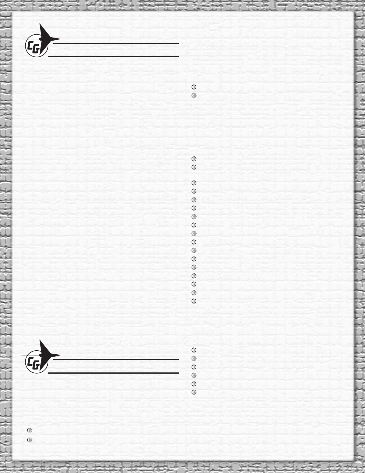
TABLE OF CONTENTS
ADDITIONAL ITEMS REQUIRED . . . . . . . . . . . . . . . . . . . 2
Radio Equipment . . . . . . . . . . . . . . . . . . . . . . . . . . . . . . 2
Hardware and Accessories . . . . . . . . . . . . . . . . . . . . . . 2
Adhesives and Building Supplies . . . . . . . . . . . . . . . . . . 2
Optional Supplies and Tools . . . . . . . . . . . . . . . . . . . . . . 2
PREPARATION . . . . . . . . . . . . . . . . . . . . . . . . . . . . . . . . . 2
ASSEMBLE THE WING . . . . . . . . . . . . . . . . . . . . . . . . . . . 3
INST ALL THE FIN . . . . . . . . . . . . . . . . . . . . . . . . . . . . . . . 3
INST ALL THE ST ABILIZER. . . . . . . . . . . . . . . . . . . . . . . . 5
INSTALL THE RADIO SYSTEM . . . . . . . . . . . . . . . . . . . . 5
FINISH THE SAILPLANE . . . . . . . . . . . . . . . . . . . . . . . . . 8
Canopy Installation. . . . . . . . . . . . . . . . . . . . . . . . . . . . . 8
Apply the Decals . . . . . . . . . . . . . . . . . . . . . . . . . . . . . 10
GET THE MODEL READY TO FLY . . . . . . . . . . . . . . . . . 11
Check the Control Directions . . . . . . . . . . . . . . . . . . . . 11
Set the Control Throws. . . . . . . . . . . . . . . . . . . . . . . . . 11
Balance the Model (C.G.). . . . . . . . . . . . . . . . . . . . . . . 12
Balance the Model Laterally. . . . . . . . . . . . . . . . . . . . . 13
CHECKING FOR WARPS . . . . . . . . . . . . . . . . . . . . . . . . 13
PREFLIGHT. . . . . . . . . . . . . . . . . . . . . . . . . . . . . . . . . . . 13
Identify Your Model. . . . . . . . . . . . . . . . . . . . . . . . . . . . 13
Charge the Batteries . . . . . . . . . . . . . . . . . . . . . . . . . . 13
Ground Check & Range Check . . . . . . . . . . . . . . . . . . 14
AMA SAFETY CODE. . . . . . . . . . . . . . . . . . . . . . . . . . . . 14
General . . . . . . . . . . . . . . . . . . . . . . . . . . . . . . . . . . . . 14
Radio Control . . . . . . . . . . . . . . . . . . . . . . . . . . . . . . . . 14
CHECK LIST . . . . . . . . . . . . . . . . . . . . . . . . . . . . . . . . . . 14
FLYING. . . . . . . . . . . . . . . . . . . . . . . . . . . . . . . . . . . . . . . 15
Mount the Wing . . . . . . . . . . . . . . . . . . . . . . . . . . . . . . 15
Trim Flights. . . . . . . . . . . . . . . . . . . . . . . . . . . . . . . . . . 15
Your First Hi-Start Launches . . . . . . . . . . . . . . . . . . . . 16
First Flights. . . . . . . . . . . . . . . . . . . . . . . . . . . . . . . . . . 16
Thermal Flying . . . . . . . . . . . . . . . . . . . . . . . . . . . . . . . 16
Facts About Thermals . . . . . . . . . . . . . . . . . . . . . . . . . 16
Thermal Soaring . . . . . . . . . . . . . . . . . . . . . . . . . . . . . 17
POINTERS FOR CONTEST FLYING. . . . . . . . . . . . . . . . 17
Ballasting . . . . . . . . . . . . . . . . . . . . . . . . . . . . . . . . . . . 18
HARDWARE AND ACCESSORIES
Following is additional hardware and accessories required
to fi nish the Sophisticated Lady ARF. Order numbers are
provided in parentheses.
1/4" Foam Rubber (GPMQ1000)
#64 Rubber Bands (HCAQ2020)
ADHESIVES AND BUILDING SUPPLIES
In addition to common household and hobby tools, this is the
“short list” of the most important items required to assemble
the Sophisticated Lady ARF. Great Planes Pro™ CA glue is
recommended.
Thin CA (1/2 oz. [15g] Thin Pro CA, GPMR6001)
Medium CA (1/2 oz. [15g] Medium Pro CA+,
GPMR6007)
6-minute Pro Epoxy (4oz [113.4g] GPMR6042)
30-minute Pro Epoxy (4oz [113.4g] GPMR6043)
Mixing Sticks (GPMR8055)
Epoxy Brushes (GPMR8060)
Epoxy Mixing Cups (GPMR8056)
Paper Towels
Masking Tape
CA applicator tips (HCAR3780)
Threadlocker thread locking cement (GPMR6060)
#11 blades (5-pack, RMXR6930)
#1 Hobby knife (RMXR6900)
#44 or 3/32" [2.4mm] drill bit
Denatured Alcohol
Wax Paper
Needle-nose Pliers
OPTIONAL SUPPLIES AND TOOLS
Here is a list of optional tools mentioned in the manual that
will help you build the Sophisticated Lady ARF.
ADDITIONAL ITEMS REQUIRED
RADIO EQUIPMENT
The Sophisticated Lady ARF requires a two-channel radio
system with standard size servos. The following servos are
recommended. A square receiver battery or a small fl at receiver
battery is required to fi t the narrow fuselage.
(2) Futaba® S-3004 Standard Servo (FUTM0004)
(1) HydriMax™ 1600mAh NiMH fl at receiver battery
(HCAM6308)
Stick–on segmented lead weight (GPMQ4485)
Hobby paints/paint brushes for painting the pilot
CA debonder (GPMR6039)
CG Machine™ (GPMR2400)
RC 56 Canopy Glue
High Start (GPMP8015)
A model airplane covering iron with a protective covering
sock may also be necessary to retighten the covering and
remove any wrinkles that may have formed after the model
was originally covered at the factory. If you don’t already have a
covering iron, the 21st Century® sealing iron (COVR2700) and
the 21st Century iron cover (COVR2702) are recommended.
2
Page 3
REPLACEMENT PARTS
GPMA4148 Wing
GPMA4149 Fuselage
GPMA4150 Tail Surfaces
GPMA4151 Canopy
GPMA4152 Decals
PREPARATION
1. Lay three or four paper towels over each other and cut
the stack into small squares. The small paper towel squares,
dampened with denatured alcohol, will come in handy for
epoxy cleanup and other general cleanup during assembly.
ASSEMBLE THE WING
1. Using 220-grit sandpaper, remove any excess glue from
the sides, top and bottom of the aluminum and plywood wing
joiner. Clean the wing joiner with denatured alcohol and a
paper towel.
2. Remove the masking tape holding all the control surfaces
to their main parts. If necessary, clean off any residual tape
glue with a couple of your paper towel squares dampened
with naptha (lighter fl uid).
3. Using a sealing iron, remove any wrinkles in the covering
before assembly.
2. Check the fi t of the wing joiner in the wing panels. Remove
any excess material from the joiner to allow the panels to fi t
together. Gather everything required for gluing the wing joiner
and wing together, including 30-minute epoxy, mixing sticks,
epoxy brush, 12" [304mm] long dowel or wire, denatured
alcohol and paper towels. Mix up 1/2 oz. [14.8cc] of 30-minute
epoxy. Working quickly, pour a generous amount into the
joiner pocket of one wing half. Use your wire or dowel to
thoroughly distribute the epoxy, coating all surfaces inside
the joiner pocket. Coat the root rib and one half of the wing
joiner that goes into the wing. Insert the joiner in the wing.
Coat the joiner pocket in the other wing half and the other
end of the wing joiner. Join the wing halves together. Then,
stand the wing on end with one of the wing tips resting on
the fl oor. Use a piece of R/C foam or something similar to
cushion and stabilize the wing so it won’t slide around. Hold
the two wing halves together with masking tape. Wipe off any
excess epoxy with a paper towel dampened with denatured
alcohol. After the epoxy has hardened, apply the included
white tape around the joint.
3
Page 4
INSTALL THE FIN
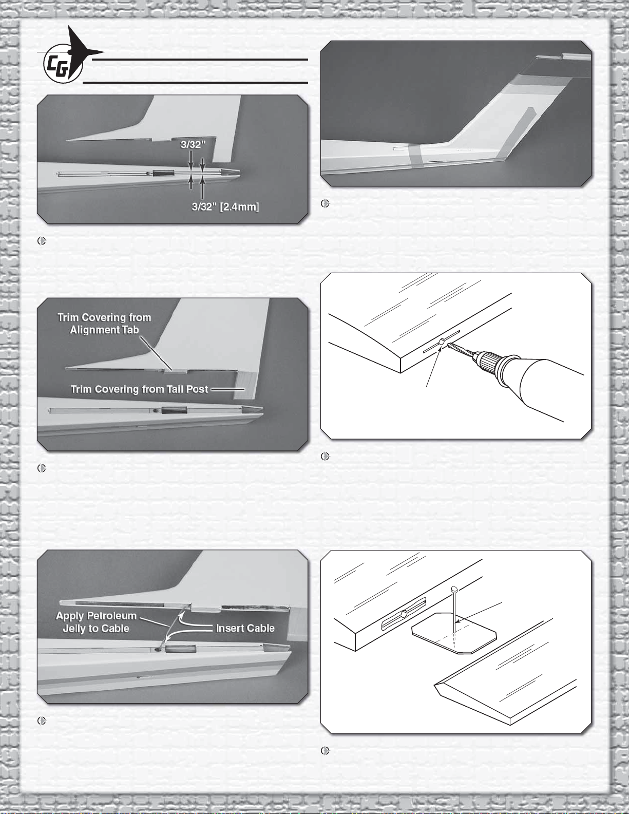
Drill a 3/32" Hole
1/2" Deep, in the Center
of the Hinge Slot
Temporary Pin
to Keep Hinge
Centered
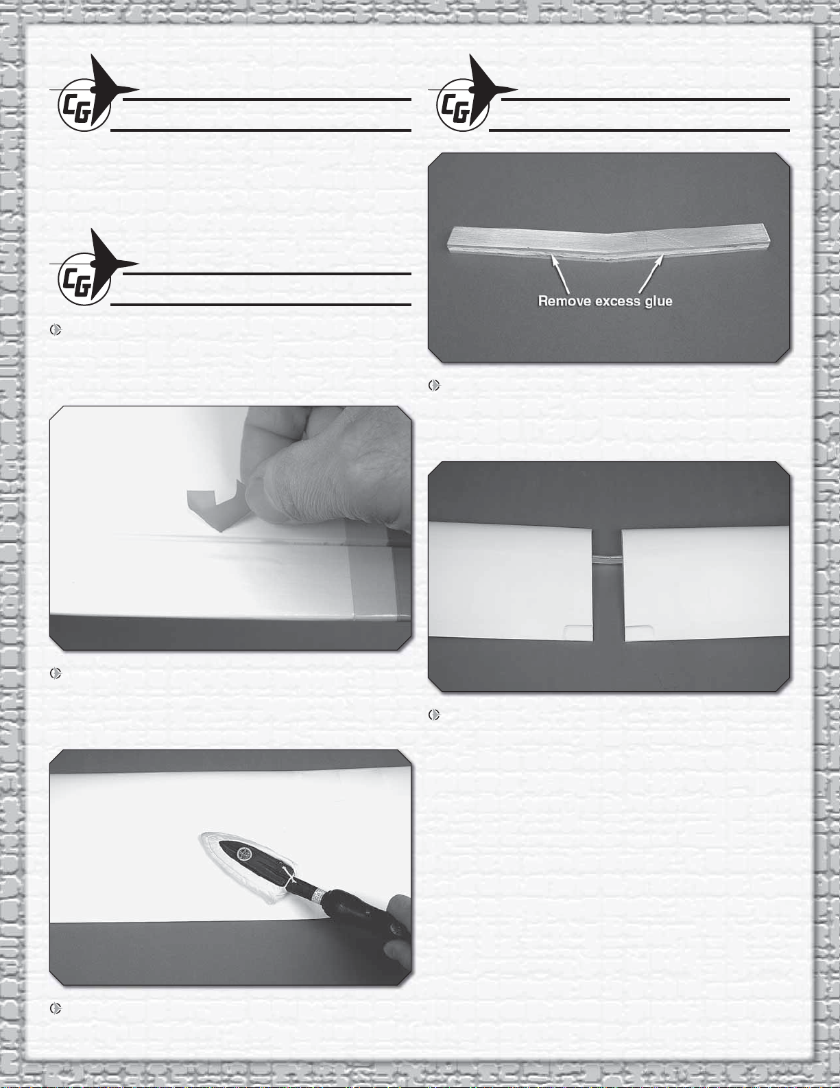
1. Use a felt tip pen to draw a centerline on the top aft end
of the fuselage. Draw a line 3/32" [2.4mm] on both sides of
the centerline. Position the fi n on the fuselage and mark on
the top of the fuselage, all the way around the fi n.
4. Use 6-minute epoxy to glue the fi n to the top of the
fuselage. Wipe off the excess epoxy with a paper towel
dampened with rubbing alcohol. Use masking tape to hold
the fi n in position, aligned with the centerline of the fuselage
and parallel to the sides.
2. Using a hobby knife with a fresh blade, cut and remove
the covering only between the two outside lines. DO NOT
cut the wood under the covering as this will weaken the
structure. Also, insert the fi n in the fuselage and mark the
tail post where it exits the fuselage. Trim the covering from
the tail post and alignment tab.
3. Insert the elevator control cable into the nylon outer
control tube in the fuselage and the fi n. Apply petroleum jelly
to the cable to insure epoxy doesn't adhere to it. Position
the fi n on the fuselage and move the cable to check that it
moves freely.
5. Drill a 3/32" [2.4mm] hole, 1/2" [13mm] deep, in the
center of the fi n and rudder hinge slots. If you use a Dremel®
Rotary Tool for this task, it will result in a cleaner hole than if
you use a slower speed drill. Drilling the hole will twist some
of the wood fi bers into the slot, making it diffi cult to insert the
hinge. Insert a hobby knife blade in the slot, working it back
and forth a few times to clean out the slot.
6. To keep the hinges centered, insert a pin in the center
of the hinges.
4
Page 5
7. Insert three hinges in the rudder and attach the rudder to
Assemble, then Apply 6 Drops
of Thin CA to the Center of
the Hinge, on Both Sides
the fi n. Remove the pins, making sure there is approximately
a 1/64" [0.4mm] gap between the rudder and fi n.
8. Defl ect the rudder 1-1/2" [38mm] in one direction and
apply six drops of thin CA to the center of the hinges. Defl ect
the rudder in the other direction and again apply six drops
of thin CA to the center of the hinges. Use a paper towel to
absorb excess CA from the hinge gap before it hardens. Do
not use CA accelerator. Allow the CA to harden slowly.
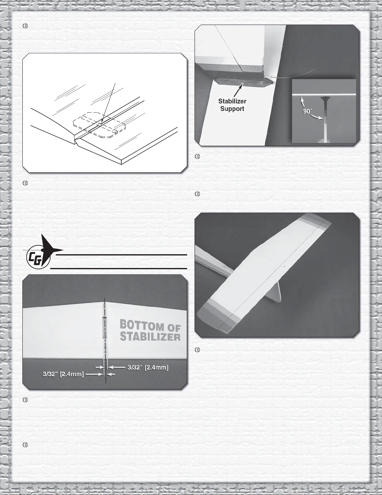
3. Position the two stabilizer supports under the stabilizer
against the fi n. Mark the outline of the supports on the fi n
and stabilizer. Use a sharp hobby knife to trim and remove
the covering 1/16" [1.5mm] inside the outline.
4. Use 6-minute epoxy to glue the stabilizer supports to
the fi n and stabilizer.
INSTALL THE STABILIZER
1. Draw a centerline on the bottom of the stabilizer. Draw
a line 3/32" [2.4mm] on each side of the centerline. Use a
hobby knife to cut and remove the covering only between the
two outside lines. DO NOT cut the wood under the covering
as this will weaken the stabilizer, causing it to fail.
5. Install the elevator using the same hinging method used
on the rudder.
2. Use 6-minute epoxy to glue the stabilizer to the top of the
fi n. Use a square to check that the stabilizer is perpendicular
to the fi n.
5
Page 6
INSTALL THE RADIO SYSTEM
Hinge Line Hinge Line
CORRECT INCORRECT
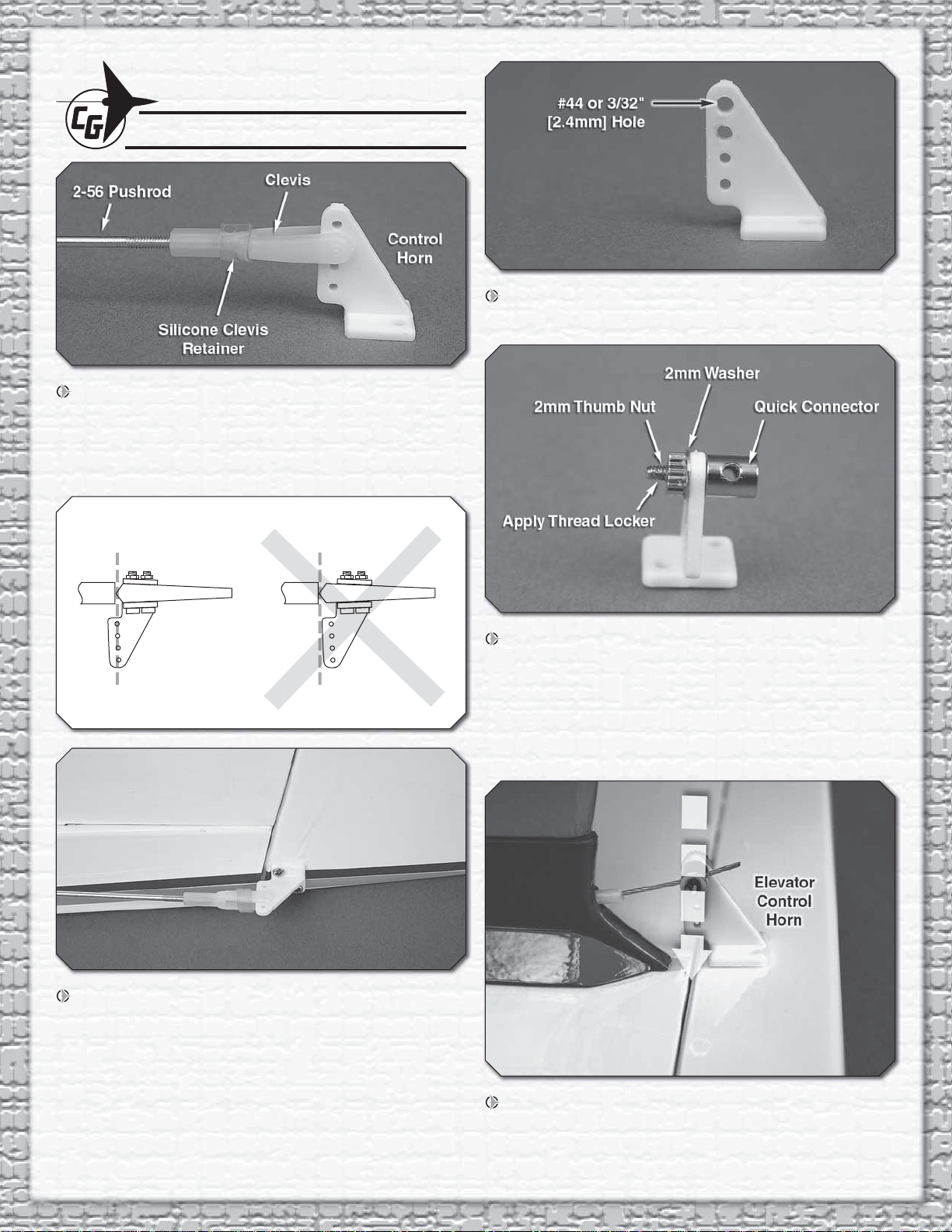
1. Separate the back plate from one of the nylon control
horns. Thread a nylon clevis 14 turns onto the 2-56 metal
pushrod. Slide a silicone clevis retainer over the end of the
clevis. Attach the clevis in the third hole from the bottom of
the control horn.
3. Use a #44 or 3/32" [2.4mm] drill bit to enlarge the outer
hole in the second nylon control horn.
2. Use a sharp hobby knife to remove the covering from
the end of the rudder guide tube. Insert the pushrod into the
rudder pushrod guide tube. Position the control horn on the
rudder so that the four holes in the control horn are aligned
with the hinge line. Drill two 3/32" [2.4mm] holes through the
rudder using the control horn as a guide. Remove the control
horn and harden the holes by applying two or three drops of
thin CA in each hole. After the CA has cured, attach the control
horn to the rudder using two 2-56 x 3/8" [9.5mm] screws and
the control horn back plate.
4. Insert the quick connector through the previously drilled
hole in the control horn. Install a 2mm washer on the quick
connector. Put a drop of threadlocker on the threads and
secure the quick connector with a 2mm thumb nut. Tighten
the nut and then slowly back it off until the quick connector
rotates freely. The threadlocker will prevent the nut from
coming loose.
5. Slide the elevator cable through the hole in the quick
connector and position the elevator control horn so that the
four holes are aligned with the elevator hinge line. Use a felt
tipped pen to mark the location of the holes.
6
Page 7

6. Drill two 3/32" [2.4mm] holes through the elevator using
Servo
Grommet
Brass Eyelet
Servo Tray
Screw
the control horn as a guide. Remove the control horn and
harden the holes by applying two or three drops of thin CA
in each hole. After the CA has hardened, attach the control
horn to the elevator using two 2-56 x 3/8" [9.5mm] screws
and the control horn back plate.
8. Wrap the receiver and receiver battery in 1/4" [6.4mm]
thick foam. Position the receiver and receiver battery in the
fuselage as shown. Remove the receiver switch cover from
the receiver switch. Position the switch cover on the outside
of the fuselage, between the receiver and receiver battery.
Mark the two mounting screw holes and the switch opening
on the fuselage. Use a sharp hobby knife to cut out the switch
opening and a 3/32" [2.4mm] drill bit to drill out the screw holes.
Mount the receiver switch on the inside of the fuselage with
the switch cover on the outside.
7. Install the servos using the hardware included with your
radio system. Again, apply a couple of drops of thin CA to
harden the screw holes.
9. Switch on the transmitter and receiver. Center the elevator
and rudder trims on the transmitter. Remove the servo arm
screw and position the servo arm so that it is perpendicular to
7
Page 8

the centerline of the servo. Cut the servo arm so it does not
touch the fuselage side, approximately 7/16" [11.1mm] from
the center of the arm. Remove the unused arms and reinstall
the servo arm. Reinstall the servo arm screw. With the rudder
centered and rudder aligned with the fi n, mark the pushrod
wire at the servo arm.
14. Install the servo arm on the elevator servo. Route the
elevator cable through the quick connector on the elevator
control horn and the elevator servo arm. Apply a drop of
threadlocker on a 3 x 5mm machine screw. Install the machine
screw in the quick connector on the elevator control horn and
tighten it against the elevator cable.
10. Bend the wire up at the mark. Cut the wire 5/16" [7.9mm]
above the bend. Secure the pushrod to the servo arm with
a nylon FasLink™. Make sure the FasLink does not hit the
fuselage side or bind against the servo arm.
11. Slide the two plywood outer pushrod tube supports
over the elevator outer pushrod tube.
12. Center the elevator servo. Trim a servo arm to fi t
perpendicular to the elevator servo. Remove the other unused
servo arms.
15. Use CA to glue the two plywood elevator outer tube
supports in the slots in the fuselage side.
13. Install a quick connector on the elevator servo arm
following the same procedure used to install it on the elevator
control horn.
8
Page 9

16. Center the elevator servo arm and the elevator. Apply
a drop of threadlocker on a 3 x 5 mm machine screw. Install
the machine screw in the quick connector on the elevator
servo arm and tighten it against the elevator cable. Trim off
the excess cable.
CANOPY INSTALLATION
1. Paint the cockpit with the color scheme of your choice.
Test the paint on a piece of plastic that was cut off of the
cockpit to make sure it will not affect the plastic. RC car
paints usually work well for this. Do not paint the edges of
the cockpit where the canopy will attach or the glue will not
hold as well. After the canopy is glued on, the canopy frame
decal will cover the glue joint. After the paint has dried, apply
the instrument decal to the instrument panel.
FINISH THE SAILPLANE
1. Use 6-minute epoxy to glue the nylon tail skid on the aft
bottom of the fuselage.
2. Using a needle nose pliers, open the eyelet slightly
so that a rubberband can be installed on the eyelet. Thread
each eyelet into the round plywood doubler until it just starts
to come out the back.
2. Remove the covering from over the wing dowel holes.
Center the wing dowels in the fuselage. Use thin CA to glue
them in position.
3. Use medium CA to glue one of the eyelets to the bottom
of the fuselage between the receiver and receiver battery. Glue
the second eyelet on the bottom of the cockpit aligned with
the eyelet in the fuselage. After the CA has hardened, thread
the eyelets in three or four turns more.
9
Page 10

4. Attach one of the rubberbands to the eyelets. It will have
to be doubled or tripled to create enough tension to hold the
back of the cockpit against the fuselage.
5. Trim the canopy 1/4" [6.4mm] outside the scribe lines.
Set the canopy over the cockpit and mark the outline of the
cockpit on the canopy. Trim the canopy to the line.
7. Remove the canopy and install the wing. Only a couple
of large rubberbands are needed to hold the wing at this time.
You will need to use at least eight rubber bands for fl ying.
8. Trim the aft end of the canopy to follow the shape of
the wing.
6. Remove the canopy and the cockpit from the fuselage.
Glue the cockpit between the lines on the canopy using canopy
glue such as J&Z R/C-56 Glue, Pacer RIC 560 Canopy Glue
or 6-minute epoxy. Use the glue sparingly.
9. Attach the threaded tow hook to the bottom of the
fuselage by threading a 3mm nut and a 3mm washer all the
way onto the tow hook. Apply a drop of threadlocker to the
threads and tighten the tow hook into the front blind nut for
the fi rst fl ights. With the tow hook threaded almost all the way
into the blind nut, make sure the tow hook is facing straight
back and tighten the 3mm nut to secure it. After the fi rst fl ights
the tow hook can be moved back to the center hole for most
10
Page 11

fl ying conditions. For contest fl ying, you may want to try the
ELEVATOR
MOVES DOWN
RUDDER
MOVES RIGHT
2-Channel
Radio Set-Up
(Standard Mode 2)
rear hole as it can help achieve a higher launch. But be careful,
as the sailplane will climb at a steeper angle and be more apt
to “pop-off” the line.
APPL Y THE DECALS
1. Use scissors or a sharp hobby knife to cut the decals from
the sheet.
2. Be certain the model is clean and free from oily fi ngerprints
and dust. Prepare a dishpan or small bucket with a mixture
of liquid dish soap and warm water—about one teaspoon of
soap per gallon of water. Submerse the decal in the soap and
water and peel off the paper backing. Note: Even though the
decals have a “sticky-back” and are not the water transfer type,
submersing them in soap & water allows accurate positioning
and reduces air bubbles underneath.
3. Position decal on the model where desired. Holding
the decal down, use a paper towel to wipe most of the
water away.
3. Make certain that the control surfaces respond in the
correct direction as shown in the diagram. If any of the controls
respond in the wrong direction, use the servo reversing in the
transmitter to reverse the servos connected to those controls.
Be certain the control surfaces have remained centered. Adjust
if necessary.
SET THE CONTROL THRO WS
4. Use a piece of soft balsa or something similar to squeegee
remaining water from under the decal. Apply the canopy trim
on the canopy.
GET THE MODEL READY TO FLY
CHECK THE CONTROL DIRECTIONS
1. Turn on the transmitter and receiver and center the trims.
If necessary, remove the servo arms from the servos and
reposition them so they are centered. Reinstall the screws
that hold on the servo arms.
To ensure a successful fi rst fl ight, set up your
Sophisticated Lady according to the control throws
specifi ed in this manual. The throws have been
determined through actual fl ight testing and accurate
record-keeping, allowing the model to perform in the
manner in which it was intended. If, after you have
become accustomed to the way the Sophisticated Lady
fl ies, you would like to change the throws to suit your
taste, that is fi ne. However, too much control throw could
make the model too responsive and diffi cult to control,
so remember, “more is not always better.”
1. Use an airplane stand or something similar to raise up
the fuselage so the horizontal stab is level.
2. With the transmitter and receiver still on, check all the
control surfaces to see if they are centered. If necessary, adjust
the clevises on the pushrods to center the control surfaces.
2. Measure the high rate elevator throw fi rst. Hold a ruler
vertically on your workbench against the trailing edge of the
elevator. Note the measurement on the ruler.
11
Page 12

3. Move the elevator up with your transmitter and move the
The pushrod farther out
means More Throw
The pushrod closer in
means Less Throw
At the Servos
The pushrod farther out
means Less Throw
The pushrod closer in
means More Throw
At the Control Surfaces
These are the recommended control surface throws:
HIGH RATE LOW RATE
ELEVATOR
3/8"
[9.5mm]
22 deg
Up
3/8"
[9.5mm]
22 deg
Down
3/16"
[4.8mm]
11 deg
Up
3/16"
[4.8mm]
11 deg
Down
RUDDER
1-1/2"
[38mm]
24 deg
Right
1-1/2"
[38mm]
24 deg
Left
1"
[25.4mm]
16 deg
Right
1"
[25.4mm]
16 deg
Left
ruler forward so it will remain contacting the trailing edge. The
distance the elevator moves up from center is the “up” elevator
throw. Measure the down elevator throw the same way.
5. Measure and set the low rate elevator throws and the
high and low rate throws for the rudder control surface the
same way.
If your radio does not have dual rates, we recommend
setting the throws at the high rate settings.
NOTE: The throws are measured at the widest part of
the elevator and rudder.
BALANCE THE MODEL (C.G.)
More than any other factor, the C.G. (center of gravity/
balance point) can have the greatest effect on how a
model fl ies and could determine whether or not your fi rst
fl ight will be successful. If you value your model and wish
to enjoy it for many fl ights, DO NOT OVERLOOK THIS
IMPORT ANT PROCEDURE. A model that is not properly
balanced may be unstable and possibly unfl yable.
At this stage the model should be in ready-to-fl y condition
with all of the components in place including the complete
radio system.
4. If necessary, adjust the location of the pushrod on the
servo arm or on the elevator horn, or program the ATVs in
your transmitter to increase or decrease the throw according
to the measurements in the control throws chart.
1. If using a Great Planes C.G. Machine, set the rulers to
3-5/8" [92mm]. If not using a C.G. Machine, use a fi ne-point
felt tip pen to mark lines on the bottom of the wing on both
sides of the fuselage 3-5/8" [92mm] back from the leading
12
Page 13

edge. Apply narrow (1/16" [2mm]) strips of tape over the lines
3-5/8" [92mm]
so you will be able to feel them when lifting the model with
your fi ngers.
This is where your model should balance for the fi rst
fl ights. Later, you may experiment by shifting the C.G. 1/8"
[3mm] forward or 1/8" [3mm] back to change the fl ying
characteristics. Moving the C.G. forward will improve
the smoothness and stability, but the model will then be
less sensitive (which may be fi ne for less-experienced
pilots). Moving the C.G. aft makes the model more
maneuverable and improves the sailplane’s response to
air currents. In any case, start at the recommended
balance point and do not at any time balance the model
outside the specifi ed range.
increasing amounts of weight on the top of the fuselage over
the location where it would be mounted inside until the model
balances. The Sophisticated Lady has a weight compartment
in the nose where lead or BBs can be added. Once the amount
of weight that is required in the nose is determined, the BBs
can be glued in using white glue.
4. IMPORT ANT: If you found it necessary to add any weight,
recheck the C.G. after the weight has been installed.
BALANCE THE MODEL LATERALLY
1. With the wing level, have an assistant help you lift the
model by the nose and the bottom of the fuse under the TE
of the fi n. Do this several times.
2. If one wing always drops when you lift the model, it means
that side is heavy. Balance the airplane by adding weight
to the other wing tip. An airplane that has been laterally
balanced will track better.
2. With the wing attached to the fuselage, and all parts of
the model installed (ready to fl y), place the model right side
up on a Great Planes CG Machine, or lift it at the balance
point you marked.
3. If the tail drops, the model is “tail heavy.” Weight will need
to be added to the nose to get the model to balance. If the
nose drops, the model is “nose heavy.” If needed, the receiver
and receiver battery can be moved aft of the servos. If weight
is required use Great Planes “stick-on” lead (GPMQ4485).
To fi nd out how much weight is required, place incrementally
CHECKING FOR WARPS
This is a very important step and should be done occasionally
throughout the fl ying season. A sailplane’s wing is most effi cient
when it is not twisted or warped at all. “Washout” (the wing’s
trailing edges are twisted up at the tips) helps make a poor
wing design fl y better by adding some stability (preventing
stalls) at slow speeds but it cuts down on the wing’s effi ciency
at normal speeds. The Sophisticated Lady ARF’s wing is
designed to fl y well at slow speeds without any washout, and
therefore we recommend you check to make sure the wings
are “fl at” using the following procedure:
Set the wing so an inner panel is resting on a fl at surface. Any
warp (twist) will show up by causing a corner of the panel to
rise off the work surface.
To remove the warp, gently twist the wing in the opposite
direction while a helper glides an iron or heat gun over the
covering on both the top and the bottom of the panel to reshrink the covering. Hold the twist until the covering cools
and then recheck for warps. It may take several tries to get a
warp out, but it is worth it as you will end up with a sailplane
that fl ies straight and true and responds to air currents like a
high performance sailplane should.
Follow the same procedure to check all four wing panels and
then go back and double check them. Sometimes you put a
warp in one wing panel while trying to fi x another. You should
also look at the tail surfaces as they too can warp.
13
Page 14

PREFLIGHT
IDENTIFY Y OUR MODEL
No matter if you fl y at an AMA sanctioned R/C club site or if
you fl y somewhere on your own, you should always have your
name, address, telephone number and AMA number on or inside
your model. It is required at all AMA R/C club fl ying sites and
AMA sanctioned fl ying events. Fill out the identifi cation tag on
page 18 and place it on or inside your model.
CHARGE THE BA TTERIES
Follow the battery charging instructions that came with your
radio control system to charge the batteries. You should always
charge your transmitter and receiver batteries the night before
you go fl ying, and at other times as recommended by the
radio manufacturer.
CAUTION: Unless the instructions that came with
your radio system state differently, the initial charge on
new transmitter and receiver batteries should be done
for 15 hours using the slow-charger that came with
the radio system. This will “condition” the batteries
so that the next charge may be done using the fastcharger of your choice. If the initial charge is done with
a fast-charger the batteries may not reach their full
capacity and you may be fl ying with batteries that are
only partially charged.
GROUND CHECK AND RANGE CHECK
Always ground check the operational range of your radio
before the fi rst fl ight of the day following the manufacturer’s
instructions that came with your radio. If the control surfaces
do not respond correctly, do not fl y! Find and correct the
problem fi rst. Look for loose servo connections or broken
wires, corroded wires on old servo connectors, poor solder
joints in your battery pack or a defective cell, or a damaged
receiver crystal from a previous crash.
an observer shall be utilized to supervise fl ying to avoid having
models fl y in the proximity of full-scale aircraft.
3) Where established, I will abide by the safety rules for the
fl ying site I use, and I will not willfully and deliberately fl y my
models in a careless, reckless and/or dangerous manner.
5) I will not fl y my model unless it is identifi ed with my name
and address or AMA number, on or in the model. Note: This
does not apply to models while being fl own indoors.
7) I will not operate models with pyrotechnics (any device that
explodes, burns, or propels a projectile of any kind).
RADIO CONTROL
1) I will have completed a successful radio equipment ground
check before the fi rst fl ight of a new or repaired model.
2) I will not fl y my model aircraft in the presence of spectators
until I become a qualified flier, unless assisted by an
experienced helper.
3) At all fl ying sites a straight or curved line(s) must be
established in front of which all fl ying takes place with the
other side for spectators. Only personnel involved with fl ying
the aircraft are allowed at or in the front of the fl ight line.
Intentional fl ying behind the fl ight line is prohibited.
4) I will operate my model using only radio control frequencies
currently allowed by the Federal Communications
Commission.
5) I will not kno wingly operate my model within three miles
of any pre-existing fl ying site except in accordance with
the frequency sharing agreement listed [in the complete
AMA Safety Code].
CHECK LIST
AMA SAFETY CODE (EXCERPTS)
Read and abide by the following excerpts from the Academy
of Model Aeronautics Safety Code. For the complete Safety
Code refer to Model A viation magazine, the AMA web site or
the Code that came with your AMA license.
GENERAL
1) I will not fl y my model aircraft in sanctioned events, air
shows, or model fl ying demonstrations until it has been
proven to be airworthy by having been previously, successfully
fl ight tested.
2) I will not fl y my model aircraft higher than approximately
400 feet [122m] within 3 miles [4.8km] of an airport without
notifying the airport operator. I will give right-of-way and avoid
fl ying in the proximity of full-scale aircraft. Where necessary,
During the last few moments of preparation your mind
may be elsewhere anticipating the excitement of the fi rst
fl ight. Because of this, you may be more likely to overlook
certain checks and procedures that should be performed
before the model is fl own. To help avoid this, a check list
is provided to make sure these important areas are not
overlooked. Many are covered in the instruction manual,
so where appropriate, refer to the manual for complete
instructions. Be sure to check the items off as they are
completed (that’s why it’s called a check list!).
1. Check the C.G. according to the measurements provided
in the manual.
2. Balance your model laterally as explained in the
instructions.
3. Use threadlocking compound to secure critical fasteners
such as the tow hook.
4. Make sure all hinges are securely glued in place.
14
Page 15

5. Reinforce holes for wood screws with thin CA where
appropriate (servo mounting screws, control horn screws, etc.).
6. Confi rm that all controls operate in the correct direction
and the throws are set up according to the manual.
7. Make sure there are silicone retainers on all the clevises
and that all servo arms are secured to the servos with the
screws included with your radio.
8. Make sure any servo leads do not interfere with other
systems (servo arms, pushrods, etc.).
9. Place your name, address, AMA number and telephone
number on or inside your model.
10. Cycle your receiver battery pack (if necessary) and
make sure it is fully charged.
11. If you wish to photograph your model, do so before
your fi rst fl ight.
12. Range check your radio when you get to the
flying field.
FLYING
MOUNT THE WING
Mount the wing to the fuselage with included eight #64 rubber
bands. Install them from front to back, crisscrossing the last
two. Never use torn or cracked rubber bands. After removing
the rubber bands from your model, store them in a container
with talcum powder or clay-type kitty litter to keep them fresh
for the next fl ying session.
If the rubber bands you will be using are different from those
recommended, consult an experienced modeler to make
certain they are strong enough, and that you have used enough
of them. If uncertain, force the front of the wing off of the wing
saddle. There should be considerable resistance! If the wing
can be forced from the fuselage without having to strain your
hands, then there are probably not enough rubber bands.
IMPORTANT: Flying a model with too few rubber
bands can be dangerous. If the wing momentarily lifts
from the fuselage and acts as though a large amount of
“up” elevator has suddenly been applied because there
are not enough rubber bands or they are too weak,
internal structural damage may result. Even worse, the
wing could actually detach from the fuselage resulting in
a crash. If the model exhibits any tendencies that indicate
there are not enough rubber bands, immediately land
and closely inspect the model for damage. If no damage
is found, add more rubber bands.
If you are fl ying with other fl yers check to make sure they are
not fl ying or testing on the same frequency as your model.
If you are an inexperienced pilot try to fi nd an experienced
pilot to help you with your fi rst fl ights. Although the
Sophisticated Lady is very easy to fl y, an experienced pilot
can save you a lot of time and possible aggravation by helping
you get your model in the air smoothly.
CAUTION (THIS APPLIES TO ALL R/C AIRPLANES):
If, while fl ying, you notice an alarming or unusual sound
such as a low-pitched “buzz,” this may indicate control
surface fl utter. Flutter occurs when a control surface
(such as an aileron or elevator) or a fl ying surface
(such as a wing or stab) rapidly vibrates up and down
(thus causing the noise). In extreme cases, if not
detected immediately, fl utter can actually cause the
control surface to detach or the fl ying surface to fail,
thus causing loss of control followed by an impending
crash. The best thing to do when fl utter is detected is
to slow the model immediately, then land as soon as
safely possible. Identify which surface fl uttered (so the
problem may be resolved) by checking all the servo
grommets for deterioration or signs of vibration. Make
certain all pushrod linkages are secure and free of
play. If it fl uttered once, under similar circumstances it
will probably fl utter again unless the problem is fi xed.
Some things which can cause fl utter are; Excessive
hinge gap; Not mounting control horns solidly; Poor fi t
of clevis pin in horn; Side-play of wire pushrods caused
by large bends; Excessive free play in servo gears;
Insecure servo mounting.
TRIM FLIGHTS
It is a good idea to do a couple of trim fl ights before each fl ying
session to make sure the plane is still in trim and the radio is
working properly. The model will survive a hard landing from
5 feet much better than it will from several hundred feet. The
fi rst few trim fl ights should be done over a grass fi eld, the
longer the grass the better (more cushion). If possible, have a
friend hand launch the sailplane the fi rst few trim fl ights. This
will allow you more time to make adjustments.
Switch the transmitter on fi rst and then the receiver. Hold the
Sophisticated Lady ARF under the wing with the nose pointed
slightly down and directly into the wind. It is very important
that it be launched with the wings level and the nose pointed
at a spot on the ground about 50 feet [15.2m] in front of you.
If the sailplane is launched with the nose up or launched too
hard, it will climb a few feet, stall and fall nose fi rst straight
down. With the nose pointed down slightly the sailplane will
accelerate down until it picks up enough fl ying speed then
level off and glide forward. With a little practice you will be
able to launch it at just the right speed so it soars straight
ahead in a long and impressive glide path. Adjust the trims
on your transmitter to get the plane to fl y straight ahead in a
smooth glide path.
Once you get the hang of launching it you can try turning the
plane during the trim fl ights by gently applying a “touch” of
right or left rudder. You can also try “fl aring” the landing by
slowly applying a touch of up elevator (pull the stick back)
15
Page 16

as the plane nears the ground. The Sophisticated Lady ARF
will continue to fl y just a few inches off of the ground for a
surprisingly long distance. It is important you don’t “over control”
the model. Make any control inputs slowly and smoothly rather
than moving the transmitter sticks abruptly.
YOUR FIRST HI-START LAUNCH
A hi-start is the most popular way to launch your Sophisticated
Lady ARF. It consists of 25'–100' [7.6 –30.5m] of rubber tubing
and 200'– 400' [61–121.9m] of string with a parachute or
streamer at the end. One end of the rubber is staked down
directly upwind of the launch point. One end of the string is
attached to the other end of the rubber tubing and the end of
the string with the parachute has a loop or ring and is attached
to the tow hook on the sailplane.
Follow the directions that came with the hi-start and lay it
out directly into the wind. Place the stake at the far upwind
edge of the fl ying fi eld so the parachute will blow back onto
the fl ying fi eld.
Switch on your transmitter and then the receiver and hook
the parachute onto the plane’s tow hook. Pull the sailplane
back approximately twice as far as the rubber tubing is long
(i.e., 100' [30.5m] of rubber tubing = 200' [61m] of pull back)
or whatever the hi-start instructions state. A “fi sh scale” is
handy for determining the correct amount of pull. For your fi rst
fl ights pull the plane back until there is approximately 8 lbs. of
tension. More tension can be used after you get acquainted
with the launching procedure.
Hold the plane above your head with the wings level and the
nose pointed slightly up and directly into the wind. Give the
plane a healthy push forward to get it fl ying and it will climb
up like a kite. You should not have to touch the elevator during
the launch but use the rudder to keep it going straight up. As
the rubber tubing relaxes the plane will fl y off the hi-start and
the parachute will bring the end of the string back towards
you. If it does not come off the high start, apply down elevator
to dip the nose of the sailplane down. The ring should then
come off the tow hook.
FIRST FLIGHTS
Find a BIG, OPEN fi eld for your fi rst fl ights - the bigger the
better as you won’t have to worry about where you need to
land. Ground based objects (trees, poles, buildings, etc.) seem
to attract model airplanes like a magnet. Again, we would
like to recommend that you fi nd an experienced pilot to
help you with these fi rst fl ights.
Note: You need to remember that your radio control
responds as if you are sitting in the cockpit of the sailplane.
When you push the transmitter stick to the right, the
rudder moves to the plane’ s right! This means that when
the plane is fl ying towards y ou it may seem like the rudder
controls are reversed (when you give “right” rudder the
plane turns to your left – which is the plane’ s “right”). It is
sometimes easier to learn to fl y the plane if you always face
your body in the direction the plane is fl ying and look over
your shoulder to watch the model.
Don’t worry about accomplishing very much on your fi rst
fl ights. Use these fl ights to get the “feel” of the controls and the
Sophisticated Lady ARF’s fl ying characteristics. Try to keep the
plane upwind and just perform some gentle “S-turns” (always
turning into the wind) until it is time to set up for landing. Have
a helper adjust the trims on your transmitter, a little at a time,
until the plane will fl y straight and level with the transmitter
sticks in their neutral positions. When it is time to land, just
continue performing the gentle “S-turns” upwind and let the
plane glide onto the ground. Don’t worry about where the
plane lands – just avoid hitting anything.
Practice fl ying directly into the wind, without letting the plane
get off course. Then, turn and come downwind until the plane is
even with you and try it again. When you are comfortable with
fl ying directly into the wind, let the plane go past you before
you start back upwind. Continue this until you can fl y directly
towards you from downwind without getting disoriented. At this
point you can start to establish a landing pattern and bring
the sailplane in for a landing from downwind. This enables the
plane to be fl own as slowly as possible for accurate landings.
THERMAL FLYING
Thermal soaring is one of the most intriguing of all aspects of
fl ying and the Sophisticated Lady ARF was designed to excel
at thermal soaring even in the hands of a novice. It can be
hard for the average person to understand how a plane can
fl y for hours and gain altitude without a motor.
FACTS ABOUT THERMALS
Thermals are a natural phenomenon that happens outside,
by the millions, every single day of the year. Thermals are
responsible for many things including forming several types
of clouds, creating breezes and the distributing plant seeds
and pollen. If you have ever seen a dust devil, you have seen
a thermal in action. Their swirling action is very similar to that
of a tornado but of course much gentler. Most thermals have
updrafts rising in the 200'–700' [61–213.4m] per minute range
but they have been known to produce updrafts of over 5,000’
per minute. The strong updrafts can tear apart a sailplane or
carry the sailplane out of sight before the pilot can get out of
the updraft.
Thermals are formed by the uneven heating of the earth
and buildings, etc. by the sun. The darker colored surfaces
absorb heat faster than the lighter colored surfaces which
refl ect a great deal of the sun’s energy back into space. These
darker areas (plowed fi elds, asphalt parking lots, tar roofs,
etc.) get warmer than the lighter areas (lakes, grassy fi elds,
forests, etc.). This causes the air above the darker areas to
be warmer than the air over the lighter areas and the more
buoyant warm air rises as the cooler, denser air forces its way
underneath the warmer air. As this warm air is forced upward
it contacts the cooler air of the higher altitudes and this large
temperature difference makes the thermal rise quicker. The
thermal is gradually cooled by the surrounding cooler air and
16
Page 17

its strength diminishes. Eventually the thermal stops rising
and any moisture contained in the once warm air condenses,
forming puffy cumulus clouds. These clouds, which mark the
tops of thermals, are usually between 2000' and 5000' high.
the airframe but it will enable it to lose altitude very quickly.
This is especially helpful if the sailplane gets sucked into a
cloud or it gets too high to see. The twirling action will give the
sun a better chance of fl ashing off of the wing and catching
your attention.
THERMAL SOARING
It takes a lot of concentration to thermal soar effectively. A
sailplane can fl y along the edge of a thermal and unless the
pilot is carefully watching the model he may not realize the
opportunity to gain some altitude. Because most thermals
are relatively small, a couple hundred feet [60m] or less at
400' [121.9 m] altitude) compared to the rest of the sky, the
sailplane will rarely fl y directly into the thermal and start rising.
Generally, the sailplane will fl y into the edge or near a thermal
and the effects the thermal has on the plane may be almost
unnoticeable. As the sailplane approaches a thermal, the
wing tip that reaches the rising air fi rst will be lifted before the
opposite wing tip. This causes the sailplane to “bank” and turn
away from where we would like the sailplane to go.
When you are thermal soaring, try to fl y as smooth and straight
as possible. Trim the sailplane to fl y in a straight line and only
touch the controls when you have to. Watch the sailplane
carefully and it will tell you what it is encountering.
When the sailplane fl ies directly into a thermal it will either start
rising or stop sinking. Either case is reason enough to start
circling, especially in a contest where every second counts.
Fly straight ahead until you feel like you are in the strongest
lift, fl y a couple of seconds farther, so that your circle will
be centered in the strongest lift, and then start circling in a
fairly tight but smooth turn. When the sailplane is low the turns
have to be tighter to stay in the strongest lift. As the plane
gains altitude, the turns can be larger and fl atter. The fl atter
the turn, the more effi cient the plane is fl ying. If you see the
sailplane falling off on one side of the circle, move your circle
over into the stronger lift. Thermals move along with the wind
so as you circle you will be swept along with it. Be careful
when thermaling, that you don’t get so far downwind you can’t
make it back to the fi eld to land.
In a gentle thermal, when you are high enough and want to
leave the thermal, add a little down trim to pick up speed and
fl y 90 degrees to the direction of the wind. If you are not real
high and want to fi nd another thermal, you may want to look
upwind of the last thermal. The same source that generated
the fi rst thermal is probably producing another. Just watch out
for “sink” which is often found behind and between thermals.
As you might expect, with all this air rising, there is also air
sinking. This air is the sailplane pilot’s nightmare that can
really make soaring challenging. Sinking air is usually not as
strong as the thermal in the same area, but can be very strong.
Down drafts of many hundreds of feet (meters) per minute
are common on a good soaring day. These down drafts can
make a sailplane look like it is falling out of the air. Because
of this, it is important that you do not let the sailplane get too
far downwind.
When encountering sink, immediately turn and fl y 90 degrees
to the direction of the wind. Apply a little “down elevator” and
pick up some speed to get out of the sink as fast as possible.
Every second you stay in the sink is precious altitude lost.
POINTERS FOR CONTEST FLYING
Pay Attention: Pay close attention to the sailplanes fl ying
before you. Watch them and try to establish where and when
the thermals are being formed. The thermals are often formed
in cycles and are fairly regular, so if you keep track of the
time intervals you will have a good idea of when and where
a thermal may be generated.
If the sailplane is fl ying along straight and all of a sudden turns,
let the plane continue to bank. You may have to add some
rudder to keep it banked. Continue turning until the sailplane
has completed a 270 degree turn, ¾ of a circle. Straighten
out the bank and fl y into whatever turned the plane. If you
encounter lift, and you won’t every time, start circling just as
you did when fl ying directly into a thermal.
Thermals are generated all day long, but the strongest thermals
are produced when the sun is directly overhead. Some of
these thermals can be very large and you may fi nd it hard
to get out of them. If you fi nd your sailplane getting too high,
don’t dive the plane to get out of the lift. Sailplanes are very
effi cient aircraft and they will build up a lot of speed and could
come apart in the rough air of a thermal. The easiest way to
lose altitude is to apply full rudder and full up elevator. This
will put the sailplane into a tight spin that will not over stress
Watch The Birds: Thermals suck up small insects that many
birds love to eat. A bunch of swallows fl ying around in one
area may indicate a thermal. Soaring birds such as hawks,
vultures and eagles are the best thermal indicators. They not
only show you where the thermal is but they also show you
where the center is. These “Masters of the sky” will often fl y
right along with the sailplanes.
Practice Those Landings: Most thermal contests are won or
lost during the landing. Establish a particular landing pattern
and try to stick to it for all landings. Learn to shift your pattern
to account for the wind and particular fl ying fi eld characteristics.
Concentrate: Keep your eye on your sailplane during your
contest fl ights. Have a helper or your counter watch the other
sailplanes in the air. Sometimes your sailplane will wiggle so
quickly or gently that you may miss it if you are not paying
17
Page 18

close attention. If you fi nd a productive thermal, don’t leave it
because your helper tells you that someone else has found
a different one.
Know Your Sailplane: Learn what your sailplane will and
won’t do and fl y within this envelope. This will allow you to ride
thermals downwind while knowing when you have to head
back to make your landing safely.
Learn From The Wind: Keep track of which way the wind is
blowing. If the wind suddenly shifts, there is some thermal
activity close to you. The air is probably being either sucked
up into a thermal or falling out of some sink. In either case it
is often a good idea to fl y in the direction the wind is blowing
if your sailplane is in the general area. This will take you
towards a thermal if there is one or away from the sink, both
of which are desirable.
BALLASTING
In strong wind conditions, you may want to add ballast (weight)
to the sailplane to increase its wing loading which increases
its normal fl ying speed. Increasing the weight of your sailplane
does not change its “glide ratio” but it does make it fl y faster.
Because of the faster sink rate, you need to be very cautious
when ballasting for a thermal contest. In duration type contests
only use ballast on very windy days that also have a lot of
thermal activity.
Add the weight as near as possible to the C.G. of the plane.
Adding 6 – 8oz (170 – 225g) will make a noticeable difference
in the sailplane’s fl ying speed and more can be added later,
if needed. Make sure to recheck the C.G. of the plane after
adding the ballast – it should not change.
Have a ball! But always stay in control
and fl y in a safe manner.
GOOD LUCK AND GREAT FLYING!
Name
Address
City, State, Zip
This model belongs to:
AMA Number
Phone Number
18
Page 19

19
Page 20

www.carlgoldbergproducts.com
Entire Contents © 2011 Hobbico,® Inc. All rights reserved. GBGA1059 v1.1 Mnl
 Loading...