

Page 1
1
INSTRUCTIONS
WARNING
A radio-controlled model is not a toy and is not intended for persons under 16 years old. Keep
this kit out of the reach of younger children, as it contains parts that could be dangerous. A radiocontrolled model is capable of causing serious bodily injury and property damage. It is the buyer's
responsibility to assemble this aircraft correctly and to properly install the motor, radio, and all other
equipment. Test and fly the finished model only in the presence and with the assistance of another
experienced R/C flyer. The model must always be operated and flown using great care and common
sense, as well as in accordance with the Safety Code of the Academy of Model Aeronautics
(www.modelaircraft.org). We suggest you join the AMA and become properly insured prior to flying
this model. Also, consult with the AMA or your local hobby dealer to find an experienced instructor in
your area. Per the Federal Communications Commission, you are required to use only those radio frequencies specified "for Model Aircraft."
LIMITED WARRANTY
Carl Goldberg Products has inspected and certified the components of this aircraft. The company urges the buyer to perform his
own inspection, prior to assembly, and to immediately request a replacement of any parts he believes to be defective for their
intended use. The company warrants replacement of any such components, provided the buyer requests such replacement within a period of 90 days from the date of purchase and provided the defective part is returned, if so requested by the company.
No other warranty, expressed or implied, is made by the company with respect to this kit. The buyer acknowledges and understands that it is his responsibility to carefully assemble the finished flying model airplane and to fly it safely. The buyer hereby
assumes full responsibility for the risk and all liability for personal or property damage or injury arising out of the buyer's use of the
components of this kit.
CARL GOLDBERG PRODUCTS, LTD.
P.O. Box 818 Oakwood GA 30566 Phone #678-450-0085 Fax # 770-532-2163 www.carlgoldbergproducts.com
© Copyright 2005 Carl Goldberg Products LTD
TM
Hot Stik ARF
Page 2

2
Congratulations on your purchase of the Hot
Stik ARF. Every effort has been made to produce a lightweight, straight, easy to assemble
aircraft. Because of its oversize control surfaces
which are double beveled to allow for extreme
throws, great care must be taken in the set-up
and flying of this airplane. Quality hardware
components have been provided to allow for 3D
set-up while maintaining adequate mechanical
advantage to eliminate flutter. It is your responsibility as an advanced pilot to fly the aircraft in
an intelligent manner. THROTTLE MANAGE-
MENT IS A MUST!!!!!!! Goldberg Models has
flown the Hot Stik ARF through a very rigorous
flight-testing schedule and have stressed the
airframe beyond all practical parameters without
a single failure. Goldberg models will NOT
warranty the Hot Stik ARF against flutter due to
improper set-up or excessive speed maneuvers.
having said that, we believe you will find the
Hot Stik ARF to be one of the most responsive,
in-the-grove aircraft on the market. Just remember to use common sense when flying this high
performance machine.
We are very proud of the construction of the Hot
Stik ARF and all of our other ARF aircraft. Each
aircraft is jig built to insure a straight true airframe. Every effort is made to build as light an
aircraft as possible. As with any professional
builder, glue is used sparingly. Please take a
moment during assembly and run a bead of
CA or aliphatic resin into the high stress
joints that you can reach such as the landing
gear plate, servo mounting trays, wing hold
down blocks, Firewall, etc. Also, during the
course of shipping from the manufacturer to our
facility in the United States, it is not uncommon
for the aircraft to experience several changes in
climate. This may cause the iron-on covering to
develop wrinkles. This is not a fault of the manufacturer. Please take a few minutes with your
heating iron and heat gun to iron down the
seams and re-shrink the covering where needed.
The results will be a beautiful aircraft with a
breathtaking finish that you will be proud to display at your flying club.
Before beginning assembly of your Hot Stik
ARF, we highly recommend that you study this
manual in its entirety. You should begin planning
your radio installation based on your choice of
engine and equipment from the beginning.
Because the Hot Stik ARF is intended for
those with some degree of modeling experience, every minute detail will not be covered. This is not a basic trainer. Assembly of
this aircraft will be easy for the experienced
modeler, and by following the instructions
within this manual and using the skills
you’ve gained during your modeling career
you will be able to produce a first class aircraft.
Building supplies needed
Hobby knife w/#11 blades
Thin CA
Medium CA
Canopy glue
30 minute epoxy
Thread lock
Diagonal wire cutters
Pliers
Assorted drill bits
Various sized screwdrivers( both Phillips and
standard head)
Tape measure
Dry-erase marker
Paper towels
Rubbing alcohol
Electrical tape
3/32, 7/64, 9/64 & 3mm Allen wrench
Wax Paper
Note:
Thread lock must be used where
ever any machine bolts are threading
into any type of nuts. If you do not
use thread lock the bolts could
become loose and fall out in flight.
Page 3

3
ADHESIVES & GLUING TECHNIQUES
CA adhesives are specially formulated to firmly glue the
plywood, hardwood, and balsa used in your model and to
withstand the vibration and stresses of high performance
flight. However, there are times, such as when you are
installing the stabilizer and fin on the fuselage and want
more set-up time for careful alignment and positioning,
then you should use epoxy. Occasionally, you also will
want to use thin CA, which "wicks" into the surrounding
areas. Aliphatic resin glue or similar water-based glues can
also be used, but they will add to the assembly time
because they dry so much more slowly than CA glue.
Remember, when ever using any CA, you must be careful
to read instructions thoroughly, as you will have only seconds for positioning of parts. Be sure to trial fit parts
together before gluing. Also, never use watery THIN type
CA glue for gluing plywood and hardwood parts. Thin CA's
do not adequately bond these areas.
CAUTION
Some people may experience an allergic reaction when
exposed to fumes from CA glue or epoxy. As with paints,
thinners, and solvents, it is always important to use glues
only where there is adequate ventilation to carry fumes
away. A fan is recommended. Also, special care must be
taken when using CA, as it will bond skin as well as other
surfaces. Before using any CA, carefully read all label precautions. When using CA, protective eye-wear and care in
keeping the glue away from the face is highly recommended. If CA does happen to get into the eye, hold lid open
and flush with water only. Seek immediate medical attention.
CONSTRUCTION TIPS
IMPORTANT: ALWAYS READ A FEW STEPS AHEAD.
This will alert you to coming instructions and will help you
plan accordingly.
COVERING
The Hot Stik ARF is covered in a premium polyester film
chosen by many of the world's top flyers for its beauty,
toughness, and ease of application and repair. It is not
uncommon for ARF's to develop a few wrinkles in transit.
If this is true of your model, the situation is easily corrected. Before you begin putting the pieces together, run
around the edge of the seams first then over the surface
of each section with an iron (either specially designed for
airplane use or the more cumbersome household iron).
Apply the heat (set at about 350° F), following along with
a soft cloth and pressing down on the covering as you go
around. This will more firmly set the covering adhesive
into the wood and keep your aircraft covering tight and
smooth in the future. Once you have ironed the seams
stay away from them with the heat or the covering will
slide when you try to shrink the middle. If this happens the
wrinkles will not come out of the covering.
ITEMS NEEDED TO COMPLETE THIS AIRCRAFT
1 24” FUEL LINE
1 ENGINE .40 TO .50
1 RADIO GUIDANCE SYSTEM
3
12” AILERON SERVO EXTENSION WIRES
2 Y-CONNECTORS
1 CA ACCELERATOR
1 2 OZ. BOTTLE CA MEDIUM GLUE
1 1/2 OZ. BOTTLE CA THIN GLUE
1 30 MINUET EPOXY
1 1/2” FOAM RUBBER
1 2” to 3” SPINNER OR ROUNDED PROP NUT
OPTIONAL:
1 PILOT FIGURE
6 SERVO ARM EXTENSIONS
NOTE: The Hot Stik ARF covering closely
matches Oracover
#890 Fluorescent red
#893 Fluorescent Lime
#891 Safety Yellow
#881 Silver
#874 Black
#930 1” Black & White Checkered
Page 4
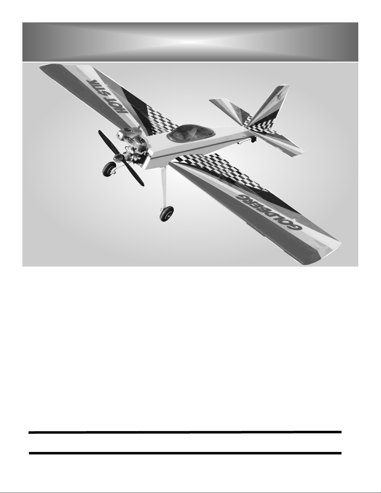
2. Bolt the landing gear in place using the two 6-
32 bolts and flat washers. Be sure to use lock-
tite on the bolts. The blind nuts are pre-
installed..
4
1. COLLECT THE FOLLOWING ITEMS
(1) ALUMINUM LANDING GEAR
(2) 5/32” AXES
(2) AXLE NUTS
(2) WHEEL COLLARS
(2) 6-32 X 1” BOLTS
(2) 2-1/2” WHEELS
(2) FLAT WASHERS
Fuselage Assembly
2. Locate the holes in the bottom of the fuselage
just ahead of the wing opening. Remove covering with an x-acto knife or soldering iron.
3. Mount the wheel on the axle using the 5\32”
wheel collar.
Page 5
5
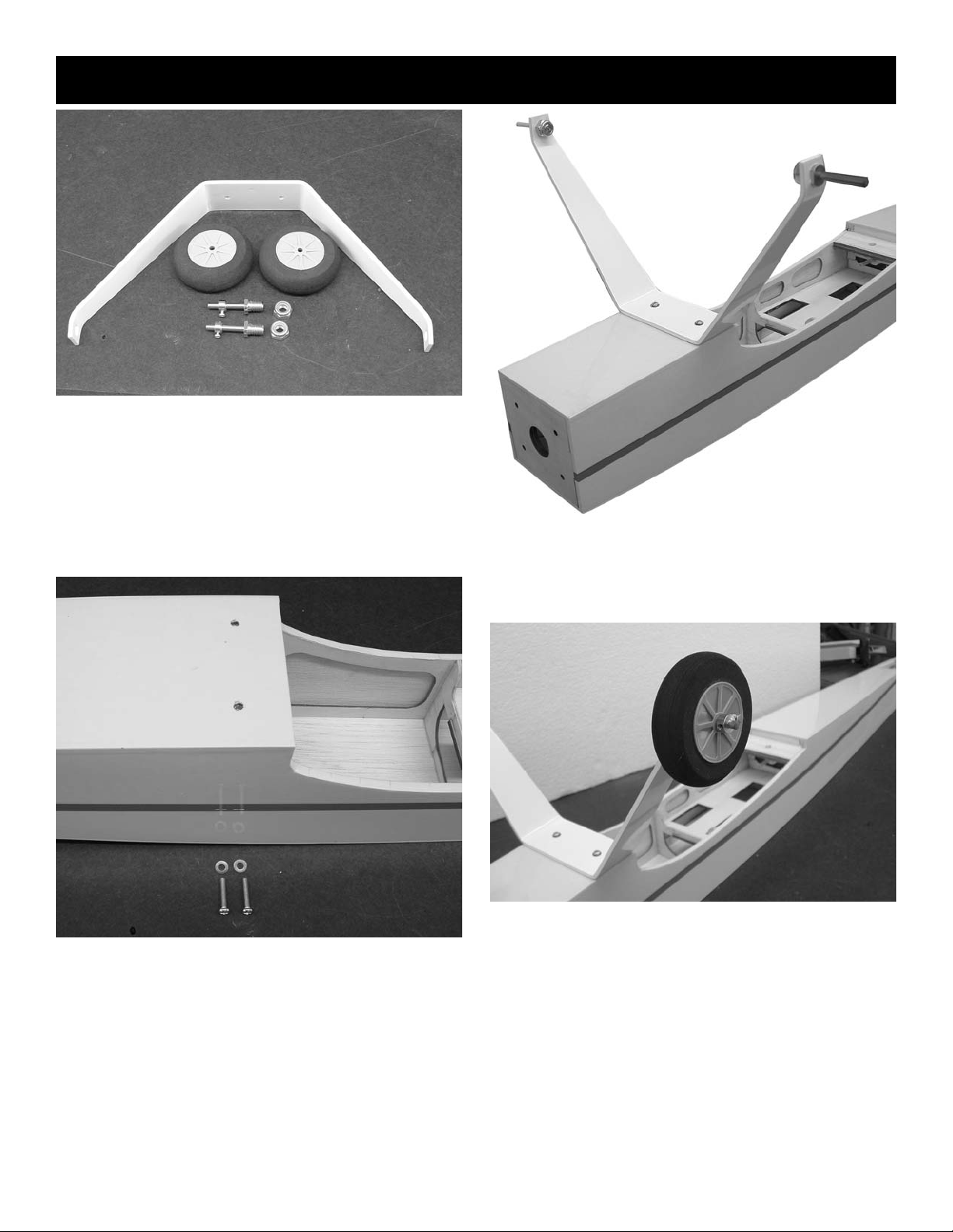
4. Find the center of the stab at the trailing edge
and make a mark at the location. Place the
stab on the fuselage and align the center mark
at the rear. Use a straight pin to hold in place.
6. Using a pencil, make a mark along the side of
the fuselage on both side of the stab.
7. Using an x-acto knife or razor blade, remove
the covering inside the line you marked. Cut
about 1/16” inside the line so bare wood will
not show after gluing in place. Be careful to
cut just the covering and not the wood as cutting into the wood will weaken the stab.
8. Locate the two elevator halves and the eleva-
tor joiner wire. The elevators should be
installed before installing the fin.
slot for elevator wire
5. Measure the stab to make sure it is square
with the fuselage. Dimensions X-X should be
the same and stab will be square.
Page 6

6
9. Mix some 5-minute epoxy and force into the
holes for the joiner wire in the elevators. Fit
the joiner wire into the holes and cover with
masking tape. Lay flat on some wax paper
and make sure both elevators are flat on the
table. Set aside till epoxy cures.
10. Locate 6 hinges and install in the elevators.
Use straight pins in the holes in the center to
make sure hinges stay centered in holes.
11. Install the elevator on the stab pushing the
hinges in until the pins are flush against the
trailing edge of the stab. When all are in place,
remove the pins and push the elevators flush
against the stab.
12. Deflect the elevator into the up position to the
full limit of its travel. From the bottom side, put
one drop of thin CA on each hinge. Deflect the
elevator to its full travel in the other direction
and apply another drop of thin CA on each
hinge. Repeat the operation for two drops of
CA on each hinge top and bottom.
13. Bolt the wing in place on the fuselage. Mix
some epoxy and install the stab on the fuselage. Sight down the fuselage and make sure
the stab is parallel with the wing. Slight pressure on either side is all that is needed to
make sure stab is aligned with wing. Set
aside till epoxy cures.
Page 7

7
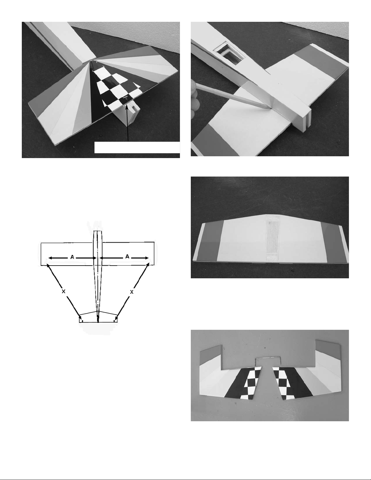
15. Remove the covering between the lines you
marked on the top of the stab where the fin
mounts.
16. Remove the covering on the post of the fin,
leave the back covered where it shown on the
rear. Make sure covering is removed on the
bottom of the fin where it sits on the stab.
remove covering
17. Mix some epoxy and install the fin. Make sure
it is centered on the front.
14. Install the fin in the notch in the rear of the
fuselage. Measure the center of the fuselage
at the front of the stab and align the fin on the
centerline. Make a mark on each side of the
fin on the stab.
remove covering
18. Locate the tail wheel bracket.
19. Mix some epoxy and install the nylon tail
wheel bracket in the slot provided.
Page 8

8
20. Locate the rudder and install the hinges using
pins in the holes to make sure the hinges go
half way into the rudder.
21. Mix some epoxy and force into the hole in the
rudder where the tail wheel tiller are
goes.Install the rudder on the fin and push
hinges in until all pins are against the fin.
Remove the pins and push rudder against the
fin. Make sure rudder tiller arm is in its slot.
Engine Mounting
1. COLLECT THE FOLLOWING ITEMS
(2) NYLON MOTOR MOUNTS
(2) 4MM X 25MM BOLTS
(2) FLAT WASHERS
2. Bolt the mounts to the firewall. The blind nuts
are pre-installed. Be sure and use Locktite on
the bolts. The mounts are spaced to fit most
.40 to .46 motors. If yours does not fit you will
have to knock the blind nuts out and reinstall
the mounts to match your engine.
22. Deflect the rudder to its full travel in one direc-
tion and using thin CA, glue the hinges in
place. Place one drop on each hinge. Deflect
full in the other directions and glue hinges
from the other side. Repeat process so each
hinge gets two drops on both sides.
Page 9

9
5. Drill a 3/16” hole in line with the throttle arm on
your engine.
4. Reinstall the engine and bolt in place using
the 6-32 bolts and aircraft lock nuts.
3. Place your engine on the mounts and mark
the location of the engine mounting holes on
the mounts. Remove the engine and drill a
5/64” hole at the marks.
Wing Assembly
1. The wing is one piece so all there is to do is
glue the aileron and flap hinges in place. Use
the straight pins in the holes in the hinges to
make sure they stay centered. Make sure
aileron is aligned with wing tip and flap does
not rub against aileron and both work freely.
2. Remove the pins and glue in the same man-
ner as we did the elevators and rudder.
Deflect the aileron and flap fully in one directions and apply one drop of thin CA. Turn the
wing over and deflect the aileron and flap in
the other direction and apply one drop to glue.
Repeat process of two drops of glue on each
hinge. Repeat for the other side of the wing.
3. Install the two servos in the cutout provided
with the output arm to the rear. You will need
a 12” extension on the out board servo. Use
the string provided to pull the servo lead to the
hole in the center of the wing. As the lead
passes the inboard servo attach the wire from
the servo and pull both to the middle.
4. Lay a straight edge along side the servo and
mark the location of the horn on the aileron
and flap. Mark both aileron servos on the outboard side of the servo (toward the tip of the
wing). If you plan to use the flaps as just flaps
you will have to mount the horn on the same
side of the servo on both sides(right flap on
the inboard side left flap on the outboard side)
If you plan to use them just as ailerons and
have them coupled to the ailerons you should
mount the horns as you did for the ailerons.
5. Mount the control horns using the #2 screws
with the nylon plate on top. Make sure the
holes for the clevis to connect to are aligned
over the hinge line.
Page 10

10
6. Repeat for the other three horns.
7. Locate the four 2-56 x 6” pushrods and install
the nylon snap link on the end. Thread the rod
into the snap link until 1/16” extends into the
opening. Slide the silicone tubing clevis keeper over the snap link.(silicone tubing 1/4” long)
1/16”
8. Install the snap link on the control horn. With
the aileron servo centered and the aileron
level, mark the point where the pushrod crosses the control arm on the servo and make a 90
degree bend. But the bend off at 3/8”. To get
full potential out of the plane you will need a
heavy duty servo arm 1 to 1-1/4” long.
3/8”
9. Install the pushrod in the servo output arm
and retain with the nylon swing in keeper.
Push the silicone clevis keeper down to the
control horn.
10.
Repeat for the other aileron and both flaps.
silicone tubing keeper
Rudder Servo Installation
1. Mount the rudder servo in the opening provid-
ed on the bottom of the fuselage just in front
of the stab. You will need a 1” extension on
the servo lead. Be sure to tape the plug
together so it does not come loose.
Page 11

11
2. Install the cover door. Clear tape will hold it in
place and be easy to remove if needed.
3. * You will need a double sided heavy duty servo
output arm.
4. Measure 1/2” from the bottom of the rudder
and 3/8” back from the hinge line and drill a
9/64” hole for the rudder control horn. Install
the 6-32 x 2-1/2” threaded rod with a nut and
washer on each side. Center the rod in the
rudder. Install the nylon control horn fittings on
each end.
7. Install the pushrods in the servo output arm
and retain using the nylon swing in keepers.
5. Locate the two 2-56 x 9” pushrods and install
the nylon snap links on the ends as we did
with the ailerons. Install the silicone keepers
and attach to the pushrod fittings on the rudder.
6.
Center the rudder servo and tape the rudder
in the neutral position. Mark the position of the
pushrods where they cross the control arm
and make a 90 degree bend. Cut the bend off
at 3/8”.
Page 12

12
Elevator Servo Installation
1. Install the elevator control horn on the inboard
edge of the elevator on the right side of the
fuselage. Align so the holes for the clevis are
centered over the hinge line.
2. Install a clevis on the end of the 2-56 x 24”
pushrod as we did with the ailerons and rudder. You may need to push the rod through the
nylon tube from the servo compartment to
open the hole in the side of the fuselage.
Insert the pushrod into nylon tube and attach
the clevis to the elevator control horn..
3. Install the elevator servo in the opening pro-
vided in the tray. The opening is made wide so
you can align different length servo arms with
the pushrod. To get full potential out of the
plane you will need a 1” to 1-1/4” heavy duty
servo arm.
4. Center the elevator servo and tape the eleva-
tor in neutral. Mark the location where the
pushrod crosses the servo arm and make a
90 degree bend. Cut the bend at 3/8”. Install
the pushrod and retain using one of the nylon
swing in keepers.
Page 13

13
Throttle Servo Installation
1. Two cutout are provided for the throttle servo,
one on each side of the fuselage. Mount your
servo on the side that matches the engine you
are using.
2. Install a clevis and keeper on the end of the
2-56 x 15” pushrod and connect to the throttle
arm on your engine.
3. Open the throttle on the engine to full and set
the servo to full throttle. Mark the pushrod and
make a 90 degree bend at the mark. The bend
will need to be made down into the fuselage
because of the close clearance of the wing.
Cut the bend at 3/8” and install in the servo
arm and retain with the nylon swing in keeper.
Fuel Tank Installation
1. COLLECT THE FOLLOWING ITEMS
(1) FUEL TANK
(1) RUBBER STOPPER
(2) CAP WASHERS
(3) ALUMINUM TUBES
(1) TANK CLUNK
(1) CAP SCREW
(1) SILICONE TUBE
2. Assemble the cap with the large washer on
top the rubber stopper and the small washer
on the bottom. Insert the screw into the center
hole. Use the long aluminum tube and bend at
a 45 degree angle to reach the top of the tank
when the cap is installed. One of the short
tubes will be the fuel pickup. Attach the silicone tube to the end of the aluminum and
adjust the length so that the clunk will be
about 1/4” off the bottom of the tank when
held vertical.
Page 14

14
3. Insert the cap in the tank, making sure the
vent line is at the top of the tank. The top of
the tank is the one closes to the cap. The
clunk should be 1/4” off the bottom of the tank.
Tighten the center screw to retain the cap in
the tank.
top of tank
4. Insert the in the opening in the bulkhead.
5. Push tank forward until the cap fits in the hole
in the firewall. The rear of the tank can be
padded with foam.
Receiver Switch and
Battery Installation
1. The switch can be mounted on either side of
the fuse, whichever is opposite the exhaust.
2. The receiver can be wrapped in foam and
placed in the opening between the servo tray
and rear of tank.
3. The battery can be mounted forward with the
receiver if necessary for balance. It will probably need to be mounted toward the rear for
balance. The opening opposite the throttle
servo can be enlarged to allow the battery to
be moved back.
Page 15

15
4. The battery can be wrapped in form and fitted
into the opening.
Final Assembly
1. Locate the 1/4-20 nylon bolt and the wing bolt
reinforcement plate. Bolt the wing in place.
2. The CG should be 4” to 4.75” behind the
leading edge of the wing measured at the
fuselage. Start off with the Cg forward and
move it back as you become more familiar
with the plane. The further back you move it
the better it will perform the 3D maneuvers but
it will also become more unstable and harder
to control.
3. Set up the control throws as follows:
Elevator Low rate 1” each direction
High rate all you can get.
Ailerons Low rate 3/4” each direction
High rate all you can get.
Rudder 1-1/2” each direction
High rate all you can get.
Flaps 1-1/2” down or they can be coupled with
the ailerons or set up as flaperons and coupled with the elevators.
Canopy Installation
1. COLLECT THE FOLLOWING ITEMS
(1) PLASTIC COCKPIT INSERT
(1) TINTED CANOPY
2. Using Canopy glue, glue the cockpit insert to
the top of the fuselage even with the leading
edge of the wing and centered on the fuselage.
3. When the insert has dried, glue the canopy in
place. Use masking tape to hold in place till
dry.
 Loading...