

Page 1
1
Congratulations on your purchase of the Obsession 3D ARF. This is a very unique dual-purpose
aircraft, capable of flying any FAI pattern sequence with ease, while exhibiting remarkable 3-D capabilities. Every effort has been made to produce a lightweight, straight, easy to assemble aircraft.
Because of its oversize control surfaces which are double beveled to allow for extreme throws, great
care must be taken in the set-up and flying of this airplane. Quality hardware components have
been provided to allow for 3D set-up while maintaining adequate mechanical advantage to eliminate
flutter. It is you responsibility as an advanced pilot to fly the aircraft in an intelligent manner. THROT-
TLE MANAGEMENT IS A MUST!!!!!!! Carl Goldberg Products has flown the Obsession 3D ARF
through a very rigorous flight-testing schedule and have stressed the airframe beyond all practical
parameters without a single failure. Carl Goldberg Products will NOT
warrant the Obsession 3D
ARF against flutter due to improper set-up or excessive speed maneuvers. having said that, we
believe you will find the Obsession 3D ARF to be one of the most responsive, in-the-grove aircraft
on the market. The Obsession 3D ARF excels at high-alpha maneuvers including Harriers (both
upright and inverted), high-alpha rolls, and high-alpha knife edge. Torque rolls, waterfalls, knife edge
loops and elevators are all within the performance parameters of this unique aircraft. Just remember
to use common sense when flying this high performance machine.
©Copyright 2004
OBSESSION
OBSESSION
3D ARF
3D ARF
P.O. Box 818 Oakwood GA 30566 Phone #678-450-0085 Fax # 770-532-2163 www.carlgoldbergproducts.com
CARL GOLDBERG PRODUCTS, LTD.
Page 2

2
We are very proud of the construction of the Obsession 3D ARF and all of our other
ARF aircraft. Each aircraft is jig built to insure a straight true airframe. Every effort is
made to build as light an aircraft as possible. As with any professional builder, glue is
used sparingly. Please take a moment during assembly and run a bead of CA or
aliphatic resin into the high stress joints, such as the landing gear plate, servo
mounting trays, wing hold down blocks, etc. Also, during the course of shipping
from the manufacturer to our facility in the United States, it is not uncommon for the aircraft to experience several changes in climate. This may cause the iron-on covering to
develop wrinkles. This is not a fault of the manufacturer. Please take a few minutes with
your heating iron and heat gun to iron down the seams and re-shrink the covering
where needed. The results will be a beautiful aircraft with a breathtaking finish that you
will be proud to display at your flying club.
Important Information
Covering coming loose is not COVERED UNDER WARRANTY. Due to temperature
changes the plane may develop some wrinkles in the covering that you will need to
remove with an iron. Be sure to seal the edges down first so that you do not cause
the covering to shrink and leave exposed areas of wood. Please inspect the plane
before beginning to assemble to make sure you are happy with it. After assembly has
begun you cannot return the kit. If you find a problem before beginning to assemble
the plane you must contact us, please do not return it to the dealer.
Page 3

3
Parts List
1. Fuselage
2. Fiberglass Cowl
3. Wing (Right & Left) with ailerons
4. Stab (Right & Left) & elevator assembly
5. Rudder
6. Fiberglass wheel pants
7. Canopy
8. Canopy Hatch
1. (2) Motor Mounts
2. (4) 8-32 x 1” Socket Head Bolts
3. (4) #6 x 3/4 Socket Head Screws
4. (4) #8 lock washers
5. (4) #8 flat washers
Motor Hardware
Landing Gear
1. Main Gear 1 left 1 right
2. (4) 4-40 x 1/2”” Button Head Bolts
3. (4) 4-40 Blind Nuts
4. (6) 8-32 x 1/2” Socket Head Bolts
5. (2) 3-1/4” main wheels
6. (2) 5/32 x 1-1/4” Axles
7. (2) Axle Locking Nuts
8. (2) 4mm flat washers
9. (2) 5/32 Wheel Collars
10. (2) 4-40 x 1/8 Set Screws
Tail wheel
1. (1) Tail wheel bracket
2. (1) 1-1/2” tail wheel
3. (2) 6-32 x 3” threaded rod
4. (2) 6-32 Hex Nut
5. (2) #6 Washer
6. (6) 1/8” Adjustable Horn bracket
Wing
1. (1) 1-1/2” x 25-3/16” Wing Tube
2. (2) 4-40 x 1/2” Bolt
COWL HARDWARE
1. (4) 4-40x 1/2”Button Head Screws
Control System
1. (5) Nylon Adjustable Control horns
2. (5) 6-32 x 2-1/4” Allen head Bolt
3. (5) Nylon Nut
5. (5) Nylon Cup Washer
6. (2) 4-40 x 2-3/16” double Threaded Rod
(Aileron)
7. (2) 4-40 x 4-7/8” Double Threaded Rod
(elevators)
8. (1) 4-40 x 6-1/4” Double Threaded Rod
(Rudder)
9. (5) 4-40 Hex Nut
10. (5) 4-40 Metal Clevis
11. (5) Metal Clevis Clips
12. (1) 2-56 x 15” Threaded Rod
(Throttle Pushrod)
13. (1) 1/8 I.D. x 14” Nylon Tubing
(Throttle Pushrod)
14. (1) EZ connector (Throttle)
Fuel Tank
1. (1) Fuel Tank
2. (1) Rubber stopper
3. (2) Metal caps for stopper
4. (1) Screw
5. (1) Clunk
6. (3) Aluminum fuel tubes
7. (1) Silicone fuel line
1. (1) 1/2” x 15-9/16” Rear Stabilizer Tube
2. (1) 1/2” x 8-11/16” Front Stabilizer Tube
2. (2) 4-40 x 1/2” Bolt
Stabilizer
Additional Items Needed
1. (5) Servo arm extensions
2. (1) Fuel Tubing 36”
3. Electrical Straps (various sizes)
4. 1/2” Foam Rubber
5. (3) 24” Servo Extensions
6. (2) 12” Servo Extensions
7. (1) Y-Harness
8. (1) 24” Thread
Page 4
4
Before beginning assembly of your Obsession
3D ARF, we highly recommend that you study
this manual in its entirety. You should begin
planning your radio installation based on your
choice of engine and equipment from the beginning.
Because the Obsession 3D ARF is intended
for those with some degree of modeling experience, every little detail will not be covered. This
is not a basic trainer. Assembly of this aircraft
will be easy for the experienced modeler, and
by following the instructions within this manual
and using the skills you’ve gained during your
modeling career you will be able to produce a
first class aircraft.
Building supplies needed
Hobby knife w/#11 blades
Thin CA
Medium CA
Canopy glue
30 minute epoxy
Thread lock
Diagonal wire cutters
Pliers
Assorted drill bits
Various sized screwdrivers( both Phillips and
standard head)
Tape measure
Dry-erase marker
Paper towels
Rubbing alcohol
Electrical tape
4-40 Tap & Die Set
3/32, 7/64, 9/64 & 3mm Allen wrench
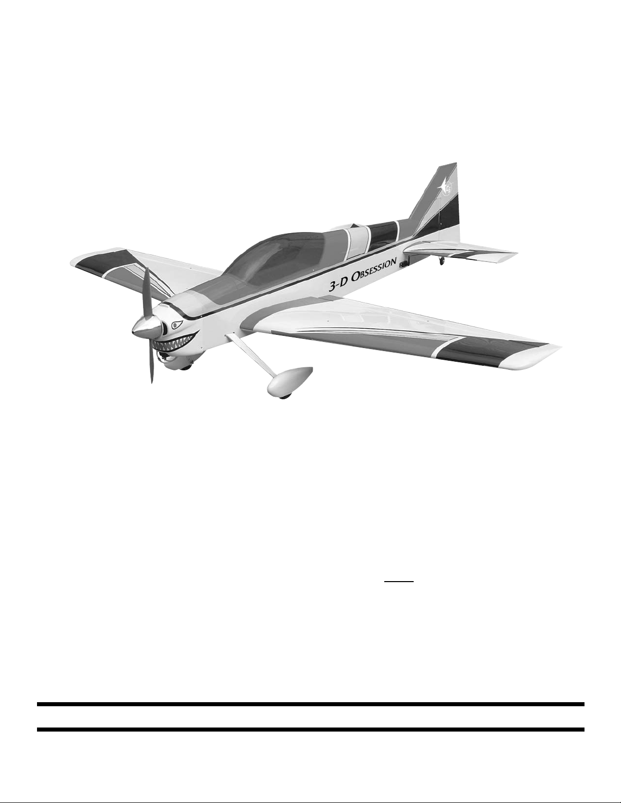
1. Begin construction by Inserting the front and
rear stabilizer tubes through the fuselage. (The
short tube goes in front).
2. Trial fit each side of the stabilizers onto the
tubes. Lightly sand the tube openings if necessary.
Note:
Now is the time to decide if you want
to glue the stabilizer to the tubes and
the fuselage, or if you wish to have
removable stabilizers.
1. Using a pencil, make an outline where the
stabilizer rest against the fuselage.
2. Remove both stabilizers from the tubes.
3. Remove the tubing from the fuselage.
4. Lightly sand the tubing using 220 sand paper.
5. Remove the covering from the fuselage
inside the outline that you made.
6. Mix up epoxy and slide the stabilizer assembly together again, allow to dry.
Mounting Stab
Collect the following parts:
(1) Left Stabilizer
(1) Right Stabilizer
(1) 1/2” x 8-11/16” Front Stabilizer Tube
(1)1/2” x 15-9/16” Rear Stabilizer Tube
(2) 4-40 x 1/2 bolts
Gluing Stabilizer
Page 5
5
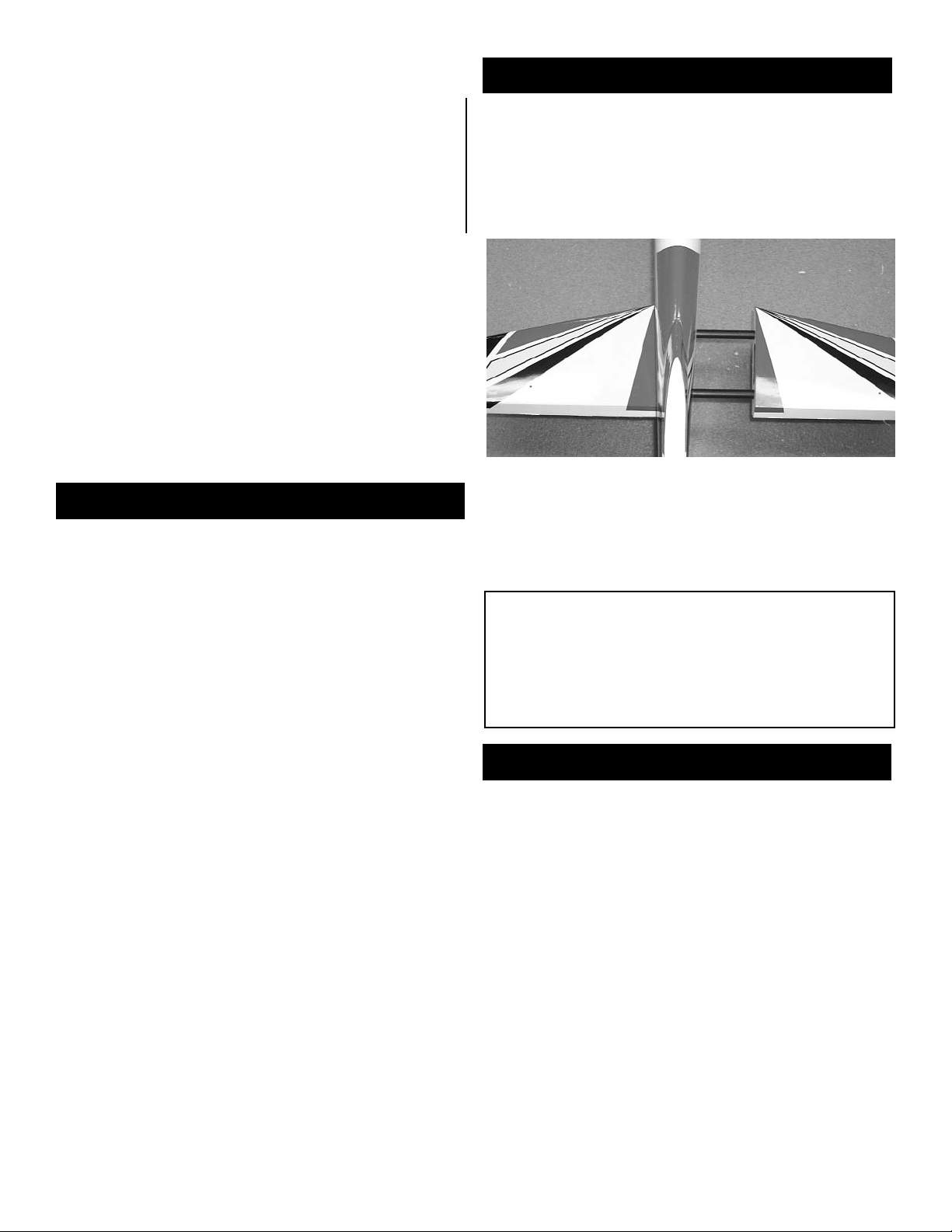
Removable Stabilizer
1. Using a drill for a 4-40 tap, drill through the
hole located on top of the stabilizer.
2. Tap the hole with a 4-40 tap.
3. Making sure that the stabilizers stay tight to
the fuselage, repeat for the other side.
4. Before flying place clear plastic tape over
the screw holes to keep the screws from
vibrating out.
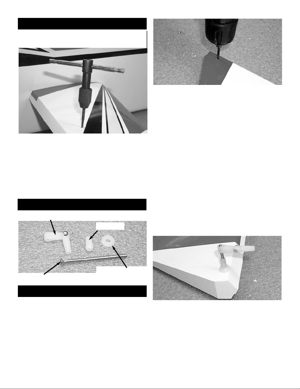
Installing Elevators
Collect the following parts:
(1) Left Elevator
(1) Right Elevator
(8) C/A Hinge
(2) Nylon Adjustable Control horns
(2) 6-32 x 2-1/4” Allen head Bolt
(2) Nylon Nut
(2) Nylon Cup Washer
Control Horn Part Names
Nylon Adjustable Control Horn
6-32 x 2-1/4” Allen head Bolt
Nylon Nut
Nylon Cup Washer
1. At the corner of the elevator, on the top and
bottom, feel for the pre-drilled hole in the plywood stiffener.
2. Using a 1/8” drill, drill half way through the
elevator hole from both top and bottom till the
drill pass through the elevator.
3. Insert the 6-32 x 2-1/4 allen head bolt into the
top of the elevator.
4. Thread the bolt all the way till the head is
flush with the top of the elevator.
5. On the bottom of the elevator, place first the
cup washer then the nylon nut onto the 6-32
bolt.
6. Using a metric allen wrench tighten the nylon
nut all the way down till it rest in the cup washer
and is tight to the elevator.
7.Thread the nylon adjustable control horn onto
the bolt.(Note: Thread the side that you can
see the cut threads in the nylon onto the
bolt)
Page 6

6
8. Insert four hinges with pins in the center into
the elevator and slide the elevator on to the correct stabilizer.
9. Place 3 drops of thin CA on both sides of
each hinge. Remove the pins.
10. Repeat steps 1 thru 9 for the other elevator.
Elevator Servo
Collect the following parts:
(2) Servos with mounting screws
(2) 24” Extensions
(2) 4-40 Metal Clevis
(2) 4-40 Hex Nut
(2) Metal Clevis Clips
(2) 4-40 x 4-1/2” Double Threaded Rod
1. Remove the covering over the elevator servo
hole just below the leading edge of the stabilizer.
2. Plug the 24” servo extension onto the servo
plug and tape securely.
3. Mount your servo using the hardware supplied with the radio.
IMPORTANT!
To ensure that any connections located
inside the Fuselage will not come loose,
either when the wires are pulled, or during
flying, always tape them securely together
with electrical tape.
3. Thread the 4-40 x 4-7/8” double threaded rod
into the nylon adjustable control horn.
9. Place a 4-40 hex nut and a metal clevis on
the other end of the threaded rod.
10. Mount the clevis to the servo arm and place
the clevis clip on th clevis.
11. Repeat 1 thru 10 for the second elevator
servo.
Note:
The servo arms that are shown are after mar-
ket arms to help increase the the amount of
servo movement.
Rudder Installation
Collect the following parts:
(1) Rudder
(3) C/A Hinge
(1) Nylon Adjustable Control horn
(1) 6-32 x 2-1/4” Allen head Bolt
(1) Nylon Nut
(1) Nylon Cup Washer
Page 7

7
Rudder Servo
Collect the following parts:
(1) Servos with mounting screws
(1) 24” Extensions
(1) 4-40 Metal Clevis
(1) 4-40 Hex Nut
(1) Metal Clevis Clips
(1) 4-40 x 6-1/4” Double Threaded Rod
1. Measure up from the bottom of the rudder
approximately 5” to locate the rudder control
horn hole.
2. Using a 1/8” drill, drill half way through the the
hole from both sides till the drill pass through the
rudder.
3. Insert the 6-32 x 2-1/4 allen head bolt into the
left side of the rudder.
4. Thread the bolt all the way till the head is
flush with the side of the rudder.
5. On the side of the rudder, place first the cup
washer then the nylon nut onto the 6-32 bolt.
6. Using a metric allen wrench tighten the nylon
nut all the way down till it rest in the cup washer
and is tight.
7.Thread the nylon adjustable control horn onto
the bolt.(Note: Thread the side that you can
see the cut threads in the nylon onto the
bolt)
8. Hinge the rudder to the fuselage using 3 CA
hinges and thin CA glue.
1. Remove the covering on the right side of the
fuselage over the rudder servo hole. The hole is
just above the elevator hinge line of the stabilizer.
2. Plug the 24” servo extension onto the servo
plug and tape securely.
3. Mount your servo using the hardware supplied with the radio.
Note:
There is a rudder servo hole on both the left
and right side of the fuselage. Using two rudder servos will give the rudder more authority for 3 D aerobatics but, will also place more
weight in the tail, which could cause CG problems.
If you choose to mount two servos then low
profile servos will probably be need to fit. Or
blocks of wood to move the rudder servos
farther apart inside the fuselage.
We have only supplied to you the hardware
for one servo horn.
4. Connect the pushrod hardware to the rudder
and servo same as you did with the elevators.
Page 8

8
Collect the following items:
(2) 6-32 x 3” All threaded rod
(2) Small White Adjustable Horn
(1) Tailwheel Bracket
(2) #4 x 1/2” Sheet Metal Screw
(2) #6 Flat Washer
(2) 6-32 Hex Nut
(2) 1/8” Wheel Collars
(2) 4-40 x 1/8 Cup Screw
(2) Tailwheel Springs
Mounting Tailwheel
1. Mark the center of the fuselage and locate
the tailwheel bracket so the the first bend is on
the rudder hinge line.
2. Mark two hole locations and make two holes
using a 3/32” bit.
3. Mount the bracket to the fuselage using the
#4 x 1/2” sheet metal screws.
4. Thread the 6-32 x 3” rod into brass nob that
is on top of the axle on the bracket.
5. Place on both ends of the threaded rod a
white horn bracket.
6. Drill a 1/8” hole located at 3/4” back from the
hinge line and 1/2” up from the bottom of the
rudder.
7. Insert the second 6-32 x 3” all threaded rod
and center it using the #6 washer with a 6-32
hex nut.
Use thread lock on the nuts.
8.Place on both ends of the threaded rod a
white horn bracket.
9. Connect one side of the spring to the horn
bracket.
10. Then cut the springs to length so that there
is a slight tension in the spring.
11. Connect the springs between the two
adjustable horn brackets.
12. Insert a 4-40 x 1/8” cup screw into each of
the 1/8” wheel collars.
13. Place one of the 1/8” wheel collars onto the
tailwheel bracket axle.
14. Slide the wheel onto the axle and place the
second wheel collar into the axle.
15. Center the wheel on the axle and tighten the
wheel collars next to the wheel.
Main Landing Gear
Collect the following items:
(2) Right & Left Landing Gear
(4) 8-32 x 1/2” Socket Head Bolts
1.Remove the covering over the screw holes for
the main landing gear on the bottom of the fuselage.
2. Remove the covering over the landing gear
slots on the side of the fuselage.
Page 9

9
3. Insert the landing gear through the slot on
the side of the fuselage.
4. Using the 8-32 x 1/2” socket head bolts and
thread lock, screw the landing gear into the blind
nuts that are already installed in the fuselage.
Wheel Pants
Collect the following items:
(2) 5-32 x 1-1/4” Axle with Locking Nut
(4) 5/32 Wheel Collars
(4) 4-40 x 1/8” Cup Screws
(4) 4-40 Blind Nuts
(4) 4-40 x 1/2” Button Head Screws
(2) 3-1/4” Wheels
1. Mount the axle to the landing gears.
2. Place the wheel pant onto the axle.
3. Align the bottom of the wheel pant with the
bottom of the landing gear.
4. Mark the hole locations on the wheel pants.
5. Drill 1/8” holes on the marks you just made.
6. Insert the 4-40 blind nuts inside the wheel
pants.
Wheel Collars
Wheel Pant
Wheel
Landing Gear
7. Mount the wheel pants back on the landing
gear along with the wheel collars and wheels.
8. Center the wheel on the axle.
Page 10

10
Engine Installation
Collect the following items:
(2) Nylon Motor mounts
(4) 8-32 x 1” Socket Head Screw
(4) #8 Washer
(4) #8 Lock Washer
(4) #6 x 3/4” Socket Head Sheet Metal Screw
Note:
The firewall is pre-drilled for the motor
mounts. the distance between the motor
mount is 1.915, this will work for the OS 120
FS or the YS 140 or any other motor needing
that clearance.
New blind nuts can easily be installed
in the back of the firewall if your choice of
motor does not fit. Measure between the
screw holes to find the vertical center line.
Locate the horizontal centerline by placing a
motor mount on the firewall and marking the
location that the outer line meets the firewall.
1. Install the motor mounts to the firewall using
the 8-32 x 1” socket head screws and the #8
washers. Use thread Lock on the screws
2. Place your engine on the motor mounts so
that the prop drive washer is 5-3/4” from the
firewall.
3. Mark the motor screw locations and drill a
3/32” hole at each location.
4. Screw the motor to the mounts using the #6 x
3/4” socket head screws.
5. Drill a 3/16” hole at the throttle pushrod location.
Throttle Servo
Collect the following items:
(1) Throttle Servo with mounting hardware
(1) .062 x 15” Wire
(1) 1/8 x 12” Tubing
1. Install the throttle servo inside the fuselage
using the hardware provided by the radio manufacturer.
2. Insert the throttle pushrod tubing through the
firewall and route it back to the throttle servo.
3. Install the EZ connector to the throttle servo
arm. Use Thread Lock
4. Make a bend at one end of the 15” wire.
5. Install the pushrod wire.
Note:
depending on the motor used your pushrod
may not be in the same location as shown.
Page 11

11
Cowl
Collect the following items:
(1) Fiberglass Cowl
(4) .#2 x 5/16” Sheet metal Screws
1. Install the fiberglass cowl onto the fuselage.
2.It helps if you make small cut outs in the fiber-
glass then slowly increase the sizes of the holes
till the cowl fits over the motor.
3. Make sure the cowl has at least a 1/16” clearance behind the spinner.
4. Screw the cowl to the fuselage using the #2 x
5/16” screws.
Fuel Tank Assembly
1. Locate the fuel tank and hardware.
the silicone tube install the clunk. This should be
adjusted in length so the clunk is about 1/4” off
the bottom of the tank. One of the long tubes
should be bent so it rest against the top of the
tank. This is the vent line. The other tube will be
the fill line. Insert the stopper in the tank and
mark the fill, vent, and pickup line so you don’t
get them mixed up later. If you are using a YS
engine which pressurizes the tank, you should
wrap the tank in strapping tape with a couple of
loops going around the cap to make sure it does
not blow off.
2. Assemble the cap by inserting the screw
through the large washer, through the black rubber and threading into the small washer on the
back side. Insert the three metal fuel lines into
the holes in the cap. The short line will be the
pickup line and will have the silicone tubing
attached to the back end. On the other end of
Mounting Fuel Tank
Collect the following items:
(1) Fuel Tank
(1) .Velcro® Strap
(1) 36” Fuel Line
1. Join the velcro together to make a long strip.
2. Thread the velcro® through the slots from the
bottom on either side of the fuel tank opening in
the tray.
3. Slide the fuel tank into the middle of the fuselage tray and under the center former.
4. Strap the Velcro® tight around the fuel tank.
5. Push the fuel tubing through the holes in the
firewall and pull them back to the fuel tank and
attach.
6. Hold the fuel lines in place using electrical
straps.
Page 12

12
Installing Receiver & Battery
Receiver
Battery
In our plane we wrapped the receiver and battery
in 1/2” foam then we mounted the receiver in
front of the fuel tank with the battery behind the
tank. Use electrical straps to hold them both in
place.
Plug a Y-harness into the receiver and pull one
plug out each side of the fuselage from the hole
just behind the wing tube hole.
Aileron Installation
Collect the following parts:
(1) Left & Right Wing
(1) Left & Right Aileron
(10) C/A Hinge
(2) Nylon Adjustable Control horns
(2) 6-32 x 2-1/4” Allen head Bolt
(2) Nylon Nut
(2) Nylon Cup Washer
1. Measure 16-3/8” from the end of the aileron to
find the hole for the control horn.
2. Using a 1/8” drill, drill half way through the
hole from both top and bottom till the drill pass
through the aileron.
3. Insert the 6-32 x 2-1/4 allen head bolt into the
top of the aileron.
4. Thread the bolt all the way till the head is
flush with the top of the aileron.
5. On the bottom of the aileron, place first the
cup washer then the nylon nut onto the 6-32
bolt.
6. Using a metric allen wrench tighten the nylon
nut all the way down till it rest in the cup washer
and is tight to the aileron.
7.Thread the nylon adjustable control horn onto
the bolt.(Note: Thread the side that you can
see the cut threads in the nylon onto the
bolt)
8. Insert five hinges with pins in the center into
the aileron and slide the aileron on to the correct wing half.
9. Place 3 drops of thin CA on both sides of
each hinge. Remove the pins.
10. Repeat steps 1 thru 9 for the other aileron.
1. Remove the covering over the aileron servo
hole on the bottom of each wing.
2. Plug the 12” servo extension onto the servo
plug and tape securely.
3. Tie 24” of sewing thread to one of the 4-40
nuts with the other end tied to your servo extension wire.
Aileron Servo Installation
Collect the following parts:
(2) Servos with mounting hardware
(2) 4-40 x 2-3/16” double Threaded Rod
(2) 4-40 Metal Clevis
(2) 4-40 Hex Nut
(2) Clevis Clips
Page 13

13
6. Thread the 4-40 x 4-7/8” double threaded rod
into the nylon adjustable control horn.
79. Place a 4-40 hex nut and a metal clevis on
the other end of the threaded rod.
8. Mount the clevis to the servo arm and place
the clevis clip on th clevis.
9. Repeat 1 thru 8 for the second aileron servo.
4. Insert the nut through the aileron servo hole
and let the nut fall through the wing and out the
hole at the root.
5. Mount your servo using the hardware supplied with the radio.
Mounting Wing to Fuselage
1. Insert the tube into one of the wing halves.
2. Trial fit each side of the wing through the fuse-
lage.
3. Lightly sand the tube openings if necessary.
4. Drill and tap the wing to the tube one side at
the time (Keep the wing tight to the fuselage).
5. Before flying place clear plastic tape over
the screw holes to keep the screws from
vibrating out.
Collect the following parts:
(1) Left & Right Wing
(1) 1-1/2” x 25-3/16” Wing Tube
(2)4-40 x 1/2” Bolt
Canopy & Hatch
Collect the following parts:
(1) Canopy
(1) Hatch
(2)4-40 x 1/2” Bolt
1. Place the hatch on the fuselage and secure
using 4-40 x 1/2 bolts.Don’t forget thread lock
2. Cover the fuselage with wax paper around the
hatch area.
8. Glue the canopy to the hatch.
Caution:
Make sure that no glue touches the
fuselage.
Page 14

Balancing & Control Throws
Your model should balance at 9-3/8” at the fuselage side to start. For extreme
3D flying you may want to move the CG back even farther after you are use to the
Obsession 3D. Just remember that the further back you go the more sensitive it will
become. With extreme throws the model can get beyond the ability of novice pilots
very quickly.
Start with the controls set at low rate with the ailerons plus or minus 1/2”, the
elevator plus or minus 1” and the rudder plus or minus 1-1/2”. High rate should be all
you can get.
Good Luck and I hope you enjoy flying the Obsession 3D.
14
The Elevator
This maneuver has your plane drop vertically in
a nose high attitude, depending on wind conditions any where from a 45 degree angle in low
wind to almost backwards in higher wind conditions. To perform it, at a high altitude with high
rates on, pull your throttle back and feed in the
elevator until you have the full high rate applied.
Use the rudder to guide the plane, and adjust
attitude with minor throttle inputs. You will loose
altitude quickly, to recover, apply full power and
fly out level. Watch out for getting too low or
applying too much rudder, it could cause the
plane to snap.
The Harrier
This maneuver has your plane in very slow forward flight in a nose high 45 degree attitude. To
perform it, enter the same way as you would an
elevator, then feed in power until the plane
maintains altitude and starts to fly forward at a
nose high attitude. Maintain it by holding up
elevator and adjusting power, use the rudder to
change direction. Using ailerons may cause the
plane to snap and should be avoided. Add
power and push the nose back over to recover.
Page 15

15
The Waterfall
This maneuver has your plane flipping around
the axis of the wing, while dropping. Starting
from a high altitude, go to low throttle and gradually pull the nose up to near vertical. Just
when the plane is about the stall, give it full
down elevator and full power. Make attitude
corrections with the rudder and ailerons to keep
the plane flipping on axis. Cut the throttle and
hold full down elevator as the plane flips around
to nose high again, add power to flip it over
again. Watch your altitude as to not get too
close to the ground. Neutralize the elevator
and add power to recover.
The Blender
This is a violent maneuver that starts with a
vertical rolling dive that stops the descent as it
changes into a flat spin. Start at a good high
altitude, go to low throttle and push the nose
down into a straight dive. Feed in full left
aileron and complete 3 rolls, then immediately
move your transmitter sticks to an inverted
snap position, down elevator, left aileron, right
rudder, all full throw. Now feed in high throttle
to flatten the spin and stop the altitude loss.
Recover by neutralizing the rudder and
ailerons, and holding a little down elevator.
After you gain some airspeed you can roll out
to upright. Use caution as this is a violent and
high G maneuver that will put a great deal of
stress on the Plane
Page 16

16
 Loading...