

Page 1
1
WARNING
A radio-controlled model is not a toy and is not intended for persons under 16 years old. Keep
this kit out of the reach of younger children, as it contains parts that could be dangerous. A radiocontrolled model is capable of causing serious bodily injury and property damage. It is the buyer's
responsibility to assemble this aircraft correctly and to properly install the motor, radio, and all other
equipment. Test and fly the finished model only in the presence and with the assistance of another
experienced R/C flyer. The model must always be operated and flown using great care and common
sense, as well as in accordance with the Safety Code of the Academy of Model Aeronautics (5151
Memorial Drive, Muncie, IN 47302, 1-800-435-9262). We suggest you join the AMA and become properly insured prior to flying this model. Also, consult with the AMA or your local hobby dealer to find an
experienced instructor in your area. Per the Federal Communications Commission, you are required
to use only those radio frequencies specified "for Model Aircraft."
LIMITED WARRANTY
Carl Goldberg Products, Ltd. has inspected and certified the components of this aircraft. The company urges the buyer to perform
his own inspection, prior to assembly, and to immediately request a replacement of any parts he believes to be defective for their
intended use. The company warrants replacement of any such components, provided the buyer requests such replacement within a period of 90 days from the date of purchase and provided the defective part is returned, if so requested by the company.
No other warranty, expressed or implied, is made by the company with respect to this kit. The buyer acknowledges and understands that it is his responsibility to carefully assemble the finished flying model airplane and to fly it safely. The buyer hereby
assumes full responsibility for the risk and all liability for personal or property damage or injury arising out of the buyer's use of the
components of this kit.
CARL GOLDBERG PRODUCTS, LTD.
P.O. Box 88 Oakwood GA 30566 Phone #678-450-0085 Fax # 770-532-2163 www.carlgoldbergproducts.com
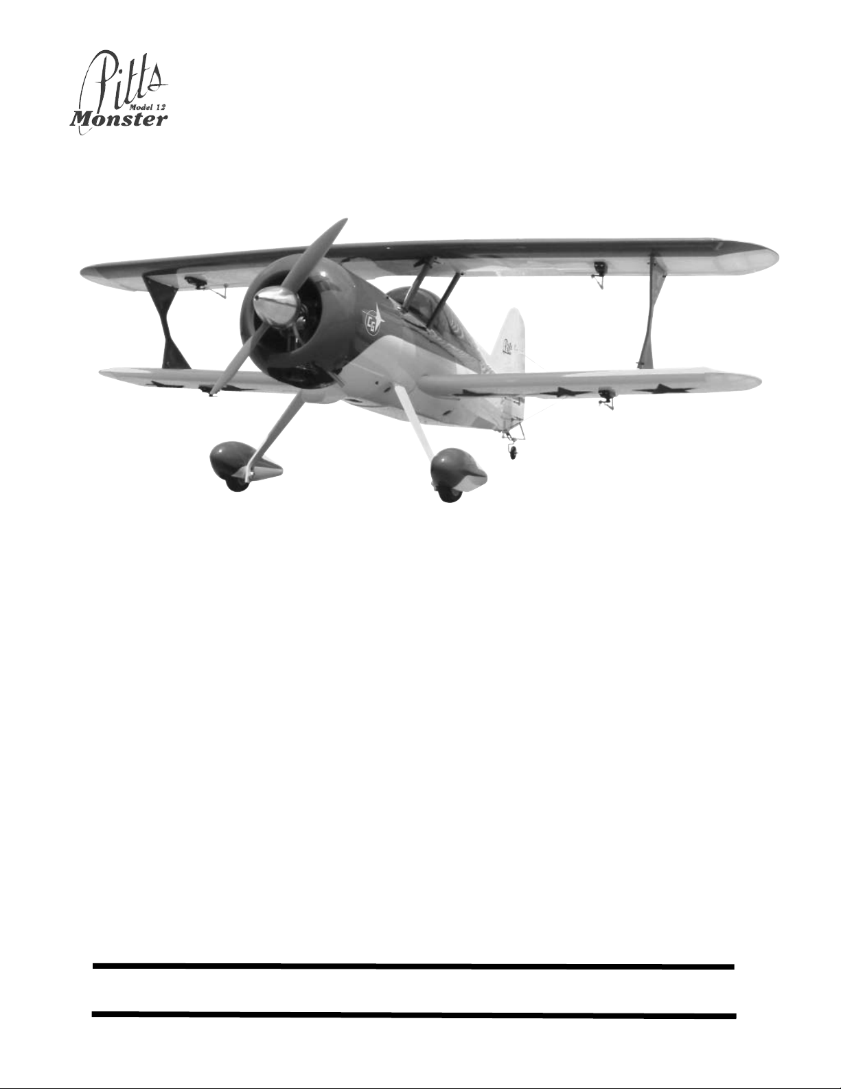
Aerobatic flying just doesn't get any better than this Pitts ARF. The classic lines of a biplane coupled with the
radial cowl, add excitement to the maneuvers you love, knife edge, split S, lumcevac, torque rolls, snaps, and
ground-hugging inverted flight. What's more, we've engineered this ARF to get you into the air with a minimum
of fuss. So take a few minutes to carefully read the introductory material and then get to work. You'll soon be
out at the field with a classic aerobatic champion!
P
Piitttt
s
s
M
M
o
o
n
n
s
stt
e
e
r
r
©Copyright 2004 Carl Goldberg Products
TM
Page 2
2
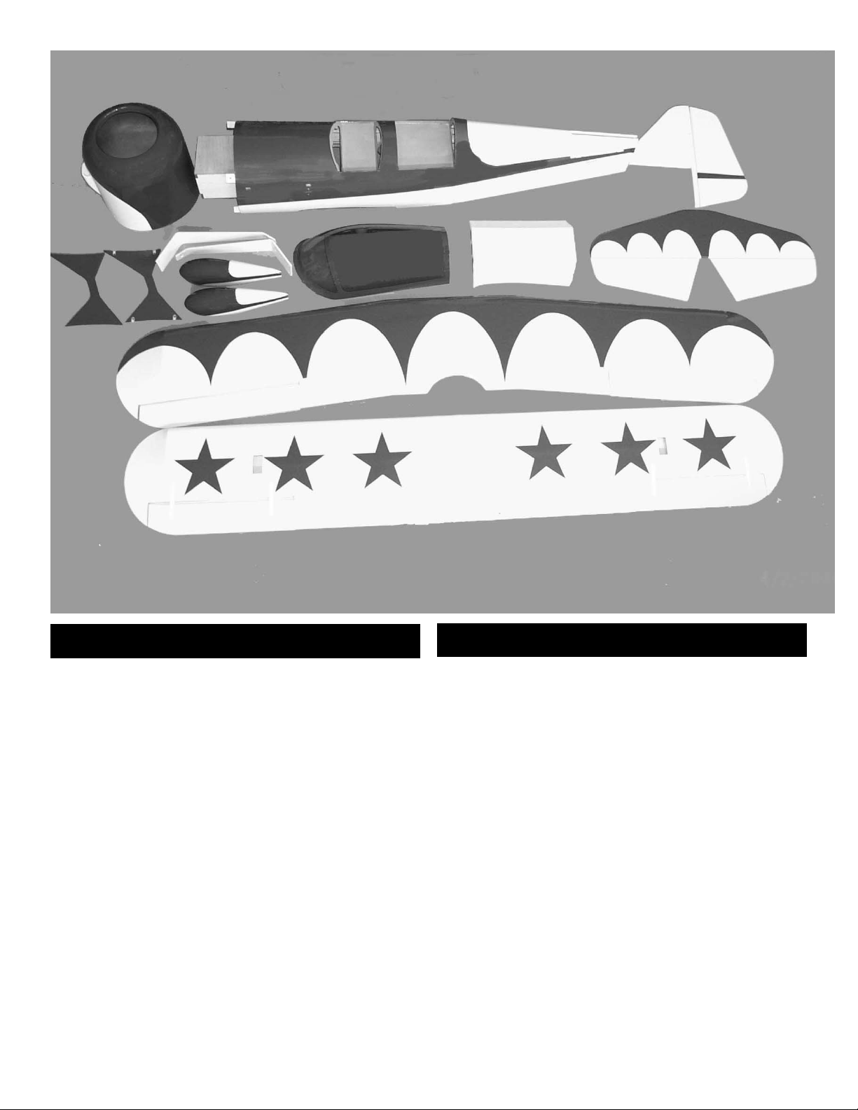
1. Fuselage
2. Cowl
3. Fin
4. Rudder
5. I-Strut (2)
6. Landing gear legs (2)
7. Wheel Pants (2)
8. Canopy
9. Belly pan
10. Stab
11. Elevators (left and right)
12. Top wing with ailerons
13. Bottom wing with ailerons.
PARTS LIST
HARDWARE LIST
Cabane Struts (4) pcs.
(12) 4-40x1/2” socket head screws
(4) #4 flat washers
I Struts (2) pcs.
(8) 4-40x1/2” socket head screws
(8) #4 Flat washers
(8) 4-40 aircraft lock nuts
(8) 1/4”x20 eye bolts
Landing gear 2pcs
(6) 6-32x3/4” socket head screws
(6) #6 Flat washers
(2) 4mm axles with lock nuts
(2) 4mm wheel collars with set screws
(2) 2-3/4” wheels
(2) 4-40 T-nuts
(2) 4-40x1/2” socket head screws.
Page 3

3
Motor Mounts (2) pcs
(4) 8-32 x 1” Socket head bolts
(4) 8-32 x 1-1/4” Socket head bolts
(4) 8-32 T-nuts
(4) aircraft lock nuts
(12) #8 flat washers
Flying wires
(13’) braided cable (for flying wires and rudder pull-
pull.
(8) metal plates
(8) 2-56 rigging couplers (4 flying wires 4 rudder)
(12) cable swages (8 flying wires 4 rudder)
(3) 2-56x1/2” screws
(3) #2 flat washers
(3) 2-56 nuts
(4) 2-56 golden clevis
(4) metal clevis clips
(2) #2 x 1/2” sheet metal screws
Pushrods
(1) 8mm x 17” wooden dowel
(2) pcs shrink tube
(1) 5/32 x 19” plastic tube
(4) 2-56x 1-3/4” pushrods threaded both end(ailerons)
(2) 2-56 x 7-1/2” Pushrods threaded one end(elevator)
(1) 2-56 x 20” threaded one end ( throttle)(1) 2-56 x 6” rod threaded one end (elevator, servo
end)
(16) golden clevis
(16) metal clevis clips
(1) pushrod connector(throttle)
(16) 2-56 nuts
Wing attachment
(2) 8mm x 1-1/2” wooden dowels
(1) ply plate( mounting bolt reinforcement)
(2) 1/4” x 2” wing mount bolts
(2) 1/4” flat washers
Tail Wheel
(1) tail wheel bracket
(1) 1-1/4” tail wheel
(2) #6x 3/4” sheet metal screws
(2) #6 flat washers
(2) springs
(1) 6-32 x 3” threaded rod
(2) nylon adjustable horn bracket
(2) 1/8” wheel collars with set screws
Control Horns
(6) 6-32 x 2” machine screws(ailerons and elevator)
(1) 6-32 x 3” threaded rod(rudder)
(8) #6 flat washers
(8) #6 nuts
(10) adjustable horn brackets
Fuel Tank (500cc 16.91oz.)
(3) feet fuel line
(1)tank stopper
(3) brass tube
(1) tank clunk
Cowl Mount
(4) 4-40 x 3/4” socket head screws
(4) 1/4” long silicone fuel tubing.
(4) #4 flat washers
Miscellaneous
(21) CA hinges
(1) 1/8” x 24” nylon tubing
(1) 4” x 12” clear plastic
Page 4

4
Before you begin assembling your Pitts ARF, take some
time to read through this entire instruction book. It is
designed to take you step-by-step through the process and
to give you added information on engine and radio selection
and set-up, balancing your aircraft, and flying your model.
The time you spend will speed the assembly process and
help you avoid problems.
PREPARING FOR ASSEMBLY
You will need a work area of approximately 24 x 70" which has been
covered to protect it from adhesive, as well as cuts and other
damage. Many people cover their work area with a sheet of
dry wall (sheet rock) and/or waxed paper t o prevent CA
Glue and Epoxy from ruining the work surface.
CONSTRUCTION TIPS
IMPORTANT: ALWAYS READ A FEW STEPS AHEAD.
This will alert you to coming instructions and will help you
plan accordingly.
Using the Parts Identification section, familiarize yourself
with the various items included in your kit box.
As you work, CHECK OFF EACH STEP in the box provided, so that you are sure you do not forget anything.
Do not hesitate to ask questions. Your local hobby dealer
and area flyers will most likely be happy to help, as they
want you to have a successful flying experience. You may
also receive technical assistance from Carl Goldberg
Products, Ltd. by telephone 1-678-450-0085.
ADHESIVES & GLUING TECHNIQUES
CA adhesives are specially formulated to firmly glue the plywood, hardwood, and balsa used in your model and to withstand the vibration and stresses of high performance flight.
However, there are times, such as when you are installing
the stabilizer and fin on the fuselage and want more setup time for careful alignment and positioning, then you
should use epoxy.. Occasionally, you also will want to use
thin CA, which "wicks" into the surrounding areas. Aliphatic
resin glue or similar water-based glues can also be used,
but they will add to the assembly time because they dry so
much more slowly than CA glue. Remember, when ever
using any CA, you must be careful to read instructions thoroughly, as you will have only seconds for positioning of
parts. Be sure to trial fit parts together before gluing. Also,
never use watery THIN type CA glue for gluing plywood and
hardwood parts. Thin CA's do not adequately bond these
areas.
CAUTION
Some people may experience an allergic reaction when
exposed to fumes from CA glue or epoxy. As with paints,
thinners, and solvents, it is always important to use glues
only where there is adequate ventilation to carry fumes
away. A fan is recommended. Also, special care must be
taken when using CA, as it will bond skin as well as other
surfaces. Before using any CA, carefully read all label precautions. When using CA, protective eye-wear and care in
keeping the glue away from the face is highly recommended. If CA does happen to get into the eye, hold lid open and
flush with water only. Seek immediate medical attention.
COVERING
The Pitts ARF is covered in a premium polyester film chosen by many of the world's top flyers for its beauty, toughness, and ease of application and repair. It is not uncommon for ARF's to develop a few wrinkles in transit. If this is
true of your model, the situation is easily corrected. Before
you begin putting the pieces together, run over the surface
of each section with an iron (either specially designed for
airplane use or the more cumbersome household iron) or
use a modeling heat gun. Apply the heat (set at about 350°
F), following along with a soft cloth and pressing down on
the covering as you go around. This will more firmly set the
covering adhesive into the wood and keep your aircraft covering tight and smooth in the future.
One of the great advantages of polyester film is that it can
be applied over itself without causing gas bubbles. This
allows you to repair your aircraft, as well as to customize it
in a number of ways. If, due to a flight mishap, you get a
hole or similar covering damage, simply trim away the
ragged edges and then apply a patch, following the directions that come with your covering , which is available at
your hobby dealer.
Important
Information
Covering coming loose is not
COVERED UNDER WARRANTY.
Due to temperature changes the
plane may develop some wrinkles in
the covering that you will need to
remove with an iron. Be sure to seal
the edges down first so that you do
not cause the covering to shrink and
leave exposed areas of wood. Please
inspect the plane before beginning to
assemble to make sure you are
happy with it. After assembly has
begun you cannot return the kit. If
you find a problem before beginning
to assemble the plane you must contact us, please do not return it to the
dealer.
Notice:
Before starting be sure all parts have not been damaged during shipping. Once
assembly has been started, all warrenty on parts are void.
Page 5

5
ITEMS NEEDED TO COMPLETE THIS AIRCRAFT
1 RADIO GUIDANCE SYSTEM (4 CHANNEL
MINIMUM REQUIRED WITH 7 SERVOS)
You will need 7 servos for the plane. we rec-
ommend a standard servo on the throttle and
4 standard servos are ok for the ailerons. The
elevator and rudder needs a 100oz of more
servo. We used the Futuba S9151 which is
132 oz.
4 6” AILERON SERVO EXTENSION WIRES
3 Y-HARNESS
1 ENGINE .61-.108 2-STROKE, .91- 1.20 4-
STROKE AND MUFFLER
1 CA ACCELERATOR
1 2 OZ. BOTTLE CA MEDIUM GLUE
1 1/2 OZ. BOTTLE CA THIN GLUE
1 20 MINUET EPOXY
1 1/4” FOAM RUBBER
OPTIONAL:
1 1/5 PILOT FIGURE
1 Prop to fit your engine
1 Spinner 3 inch
NOTE: The Pitts ARF covering matches
Yellow(#885), Blue(#872) Oracover.
TOOLS AND SUPPLIES FOR ASSEMBLY.
MODELING OR UTILITY KNIFE
WORK SURFACE (24" X70")
ELECTRIC DRILL
1/16”, 3/32”,1/8", 3/16”, 5/32”, 1/4”, 5/64”
7/32” DRILL BITS
SMALL STANDARD & PHILLIPS SCREW-
DRIVERS
MASKING TAPE
NEEDLE NOSE PLIERS
MOTO TOOL
24” RULER
FLEXIBLE STRAIGHT-EDGE
30-60-90° x 6" TRIANGLE
SOFT PENCIL
A FEW STRAIGHT OR "T" PINS
ADJUSTABLE WRENCH
WIRE CUTTER (DYKES)
OPTIONAL HEAT GUN/COVERING IRON
ACID BRUSH
ELECTRICAL TAPE
PIECE OF MEDIUM SANDPAPER
5 FT. LENGTH OF STRING
Caution:
Before starting, carefully go over all high
stress areas with an epoxy or wood glue to
confirm all areas are well glued.
Page 6
6
WING ASSEMBLY
1. Collect the following parts:
(1) Left wing
(1) Right wing
(1) Left aileron
(1) Right aileron
(12) CA hinges
AILERON INSTALLATION
2. Locate the pre-cut aileron hinge slots in both
wing halves. Using a hobby knife (#11 blade),
slide the blade into each slot to make sure it
is cleanly cut.
Repeat this process with the ailerons, mak-
ing sure all hinge slots are clean.
3. Place a straight pin into the center of each of
the four CA hinges.
Slide each hinge into the hinge slots on one of
the wing halves. The pin will prevent the
hinges from going further than halfway into the
wing.
4.
Select the aileron for the wing on which you
are working and insert the exposed half of
each hinge into the aileron slots.
4. Select the aileron for the wing on which you
are working and insert the exposed half of
each hinge into the aileron slots.
Slide the aileron toward the wing until no
gap remains between the aileron and the
wing.
5.
Carefully check the alignment of the aileron.
It should be centered, with about 1/32" on
either end.
When satisfied with the alignment, remove
the straight pins, being sure to keep the
aileron tight to the wing. You may wish to
apply a few pieces of masking tape to keep
the pieces in place.
6. Keeping the aileron and wing in position,
deflect the surface to it’s full deflection and
apply 3 or 4 drops of CA glue to the small
exposed area of each hinge.
Turn the assembly over and again apply 3 or 4
drops of CA glue to the exposed hinge surfaces.
Allow to dry for 10 minutes before flexing the
aileron.
7.
Repeat the above steps for the other three
wing ailerons.
Page 7
7
AILERON SERVO INSTALLATION
Note: The following pictures may not exactly match
the hardware you are using. Always check the
radio manufacturer's instructions when installing
radio equipment.
1. Collect the following items:
(4)Servo mounting screw (supplied with radio)
(1)Servo with rubber grommet (supplied with
radio)
(4) Servo extensions “6”
IMPORTANT! To ensure that any connections locat-
ed inside the wing will not come loose, either when
the wires are pulled, or during flying, always tape
them securely together with electrical tape.
4. Making sure to use the correct servo for the
opening, attach the servo wire to the 6" extension and securely tape the connection.
Locate the string inside the aileron servo
mount, and the other end in the exit hole.The
hole in the top wing is just behind the front
cabane mount, The bottom wing has the hole
in the middle of the center section.
Tie the string to the aileron extension by loop-
ing it through the opening between the wires
on the plug and taping with masking tape.
5.
Grasping the string, SLOWLY pull until the
end of the 6" extension comes out of the hole.
Tape the extension securely to the wing, so
that it will not slide back in while you are working.
Secure servo with the screws supplied with
the radio.
Repeat for the other three wing servos.
AILERON CONTROL HORN INSTALLATION
1. Collect the following items
(8) 2-56 Golden Clevis
(8) Clevis Clips
(8) 2-56 Hex Nut
(4) 2-56 x 1-3/4” threaded both ends wire
(4) 6-32 x 2” Bolt
(4) 6-32 Hex nut
(4) #6 Washer
(4) 6-32 Horn Bracket
2. With the aileron servo in place, make a mark
at a 90º degree angle to the trailing edge and
in line with the servo arm.
3.
Use the mark to locate the hard point installed
in the aileron( dowel with hole in middle).
4. Using a 9/64" drill bit, open the hole in the
aileron through to the top side.
HINT: Drill the hole from the bottom half way.
Then drill down to the hole from the top of
the aileron.
5. Insert the 6-32 x 2” screw from the top through
the aileron.
Place the #6 washer and the 6-32 hex nut on
the bolt and tighten. Make sure that you use
thread lock on the bolt and nut.
Screw the adjustable horn bracket on the
bolt.
Page 8
8
6. Thread on to one end of a 2-56 x 1-
3/4” pushrod a nut and Golden Clevis.
Mount the pushrod onto the the horn brack-
et.
Thread the other 2-56 clevis and nut on the
other end.
Install the rod in the control arm.
Slide the clevis clip on to each of the Golden
Clevis pins.
Repeat the above steps for the other three
ailerons.
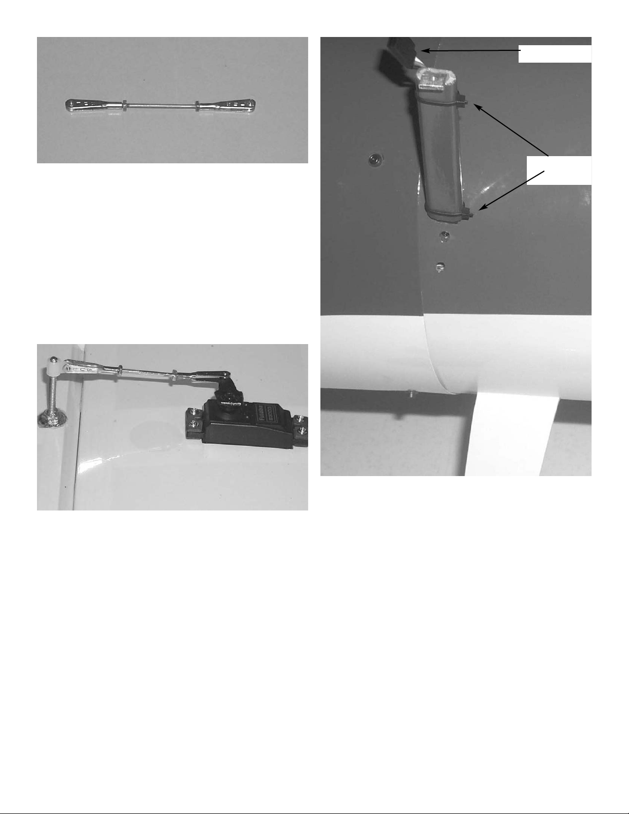
7. You will need a Y-connector for the top aileron
servos. It will exit the fuselage through a hole
just to the inside of the front cabane strut. Use
cable ties to hold it to the cabane strut so the
plug is at the top on each side. You can then
plug the ailerons in and attach the top wing.
aileron plug
cable ties
Page 9
9
Before mounting the tail the bottom
wing should be installed.
Collect the following items
(1) Fuselage
(1) Bottom wing
(2) Wing dowels (8mm x 40mm)
(2) 1/4” x 2” wing bolts
(1) Trailing edge reinforcement plate. 1/8” ply.
1. Epoxy the dowels in the pre-drilled holes in the
leading edge
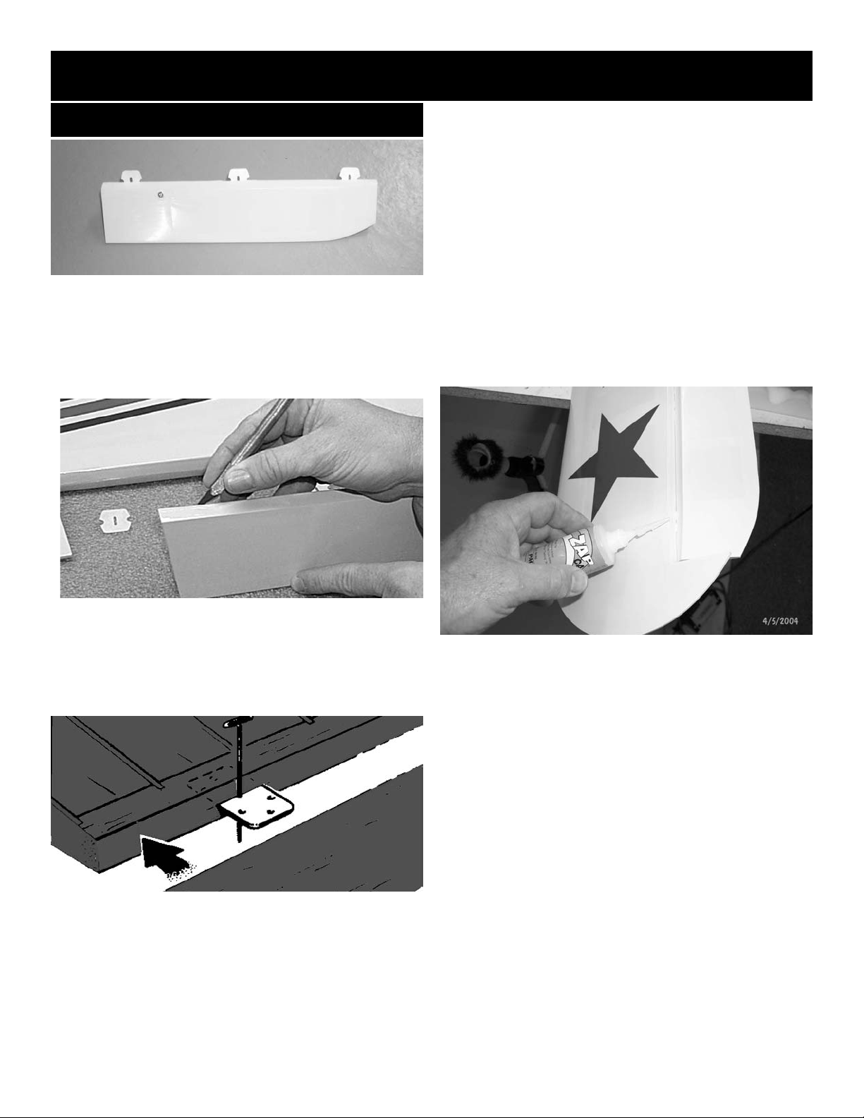
2. Lay the 1/8” plywood plate over the holes in the
trailing edge of the wing and insert the wing bolts
for alignment. Use a pen and mark the outline of
the plate on the covering.
3. Remove the covering by cutting about 1/8”
inside the line you just drew. Be careful and
do not cut into the wood.
4. Use epoxy and glue the plate in place. Insert
the wing bolts to make sure the holes are
aligned and clamp into place till dry.
5. Set the wing in place with the dowels inserted
into the bulkhead and install the wing bolts.
Bottom Wing Mounting
Caution:
Do not glue the bolts!
Page 10

10
Collect the following items
(1) Stab
(1) Fuselage (with bottom wing installed)
(1) Fin
Tail Construction.
A
A
B
B
1. Install stab in opening at rear of fuselage.
Measure to make sure it is centered ( dimension B on
each side should be the same. Now measure dimension A and move stab till they are the same.
2. Sight the stab from the front and rear of the
plane and make sure it is parallel to the wing. If necessary sand the saddle on one side to make stab align
with wing. Do not go any farther till the stab is level to
the wing.
equal
3. When satisfied with the alignment, mark the
outline of the fuselage on the stab top and bottom.
4. .Using a sharp knife or razor blade, remove the
covering inside the lines you marked both top and
bottom. Cut 1/16” inside the lines so bare wood does
not show when glued in place. Be careful and do not
cut into the wood as this will weaken the structure.
5. Apply epoxy on the fuselage and the stab and
slide back into position using the lines you drew on
the stab. Use rubbing alcohol the clean the epoxy
that will get on the surface of the stab. Check the
alignment and set aside until epoxy cures.
Page 11

11
6. Install the fin in the slot and check the alignment. It can be adjusted a small amount by sanding
the fin post area where it goes into the fuselage. It
should not need any adjustment. Mark the outline of
the fuselage on both sides. Also mark the outline of
the fin post where it goes into the rear of the fuselage.
Mark here
also
7. Remove the covering inside the lines you
marked just as you did on the stab.
8. Mix epoxy and apply to opening in fuselage
on top and the back section where the fin post fits.
Reinstall the fin and check alignment. Set aside till
cured.
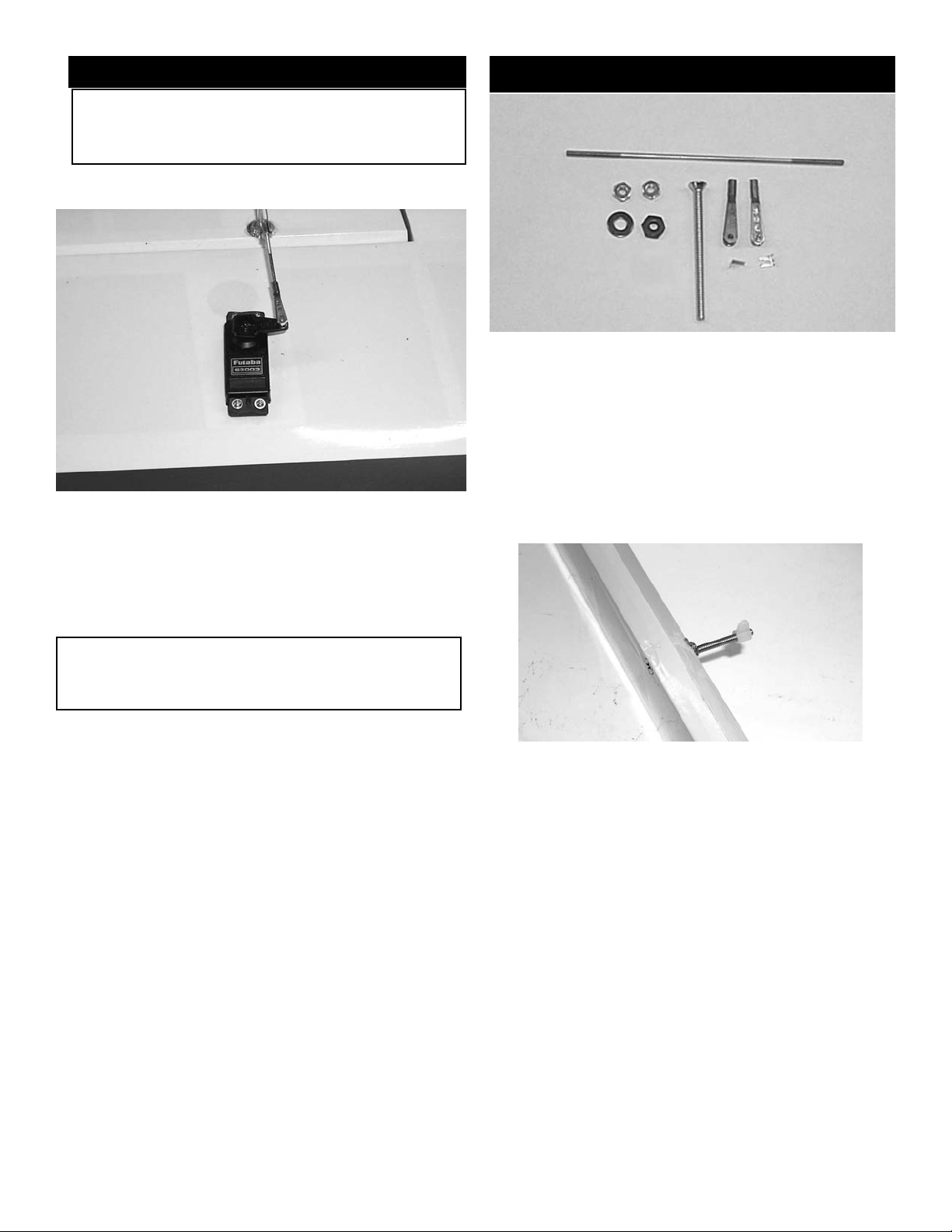
Elevator Control Horns
1. Collect the following items.
(1) 6-32 x 3” threaded rod (rudder horn)
(2) 6-32 x 2” bolts(elevator horns)
(4) 6-32 nuts
(4) #6 flat washers
(6) adjustable horn brackets.
Rudder-Elevator Control Horn
3. Locate the hole for the elevator horn and
install the 6-32 x 2” bolt with a washer and nut on the
bottom side. Use locktite or CA to secure the nut.
Install a adjustable horn bracket on the end. Repeat
for other elevator.
2 Install the 6-32 x 3” threaded rod in the
predrilled hole in the rudder hard point(dowel with
hole). The hole will be under the covering and can be
located by holding up to a light. Use a #6 washer on
each side and locktite or CA glue the nuts in place.
Install two horn brackets on each side, one faces forward for the control horn and the inside one faces
rearward to attach to the tail wheel spring.
4. Hinge both elevator and rudder to stab and
fin using the same method used on the ailerons.
Page 12

12
2. Slide gear leg into slot on side of fuselage and
install retaining bolts through access holes on the side
and middle of fuselage. Be sure to use thread lock on
the bolts. The blind nuts are already installed.
Bolt access holes
1. Collect the following items.
(2) Landing gear legs
(6) 6-32X3/4” Socket head screws
(6) #6 flat washers
(2) Wheel pants, one left one right
(2) 4mm axles with lock nuts
(4) 4mm wheel collars
(2) 2-3/4” wheels
(2) 4-40 x t-nuts
(2) 4-40 x 1/2” socket head bolts.
Landing Gear Installation
3. Install each axle using the locking nut. Be
careful not to over tighten the nut, it looks like a large
bolt but it has been drilled out for the axle and can
be broken if too much torque is applied.
4. Install one wheel collar on each axle with
3/16” between the collar and the axle nut. This will
space the wheel in the center of the wheel pant.
Page 13

13
5. The wheel pants have the 1/2” hole predrilled in
each pant. The 1/8” hole for the mounting bolt must be
drilled.
6. Block the tail of the plane up so that the fuselage is sitting level. Put the wheel inside the pant and
slide both on the axle together.
While holding the wheel pant level, mark the
location of the mounting bolt by using a 1/8” drill and
inserting it through the predrilled hole on the landing
gear leg
7. Remove the wheel pant and drill a 5/32” hole
at the location you marked. Insert the blind nut on
the inside and pull it tight using the 4-40 mounting
bolt. Lock in place with CA glue being careful not to
get it in the threads.
8. Reinstall the wheel and wheel pant and retain
with the other 4mm wheel collar. Align the wheel pant
on the gear leg with the hole you drilled for the blind
nut. Install the 4-40 x 1/2” socket head screw.
Don’t forget to use locktite to make sure it does not
come loose.
Repeat for other wheel pant.
Page 14

14
Tail wheel Mounting
1. Collect the following parts:
(1) tail wheel bracket
(1) tail wheel
(2) 1/8” wheel collars
(2) tail wheel springs
(2) #6 x 1/2” sheet metal screws\
(2) #6 flat washers
(2) nylon horn brackets(1) #6-32 threaded rod 3” long
2. Screw the 6-32x3” threaded rod into the brass
fitting on top of the tail wheel bracket. Center it
up and then screw the adjustable horn bracket
on, one on each end.
3. Install one 1/8” wheel collar, the tail wheel
and then the other 1/8” wheel collar.
4. Mount the tail wheel bracket to the fuselage
using the two #6x3/4” sheet metal screws and two #6
flat washers. Align the bend in the bracket with the
back edge of the fuselage.
Page 15

15
6. Twist the end of the spring on to the horn
bracket. Insert the long wire end around the
second horn bracket. Twist the wire so that it
will stay hooked to the bracket.
5. Remove from the tailwheel springs approxi-
mately 1/2” from the other side of the long wire.
On the side of the spring that you just cut off,
bend 2 or 3 coils of the spring out so that they
can hook through the horn bracket.
7. Repeat for other side.
Page 16

16
Top Wing Mounting
1. Locate the following items.
(4) cabane struts
(2) I-Struts
(1) Top Wing
(1) Bottom Wing
(1) Fuselage
(2) 1/4-20 x 2” wing bolts
(20)4-40x 5/8” socket head screws
(12) #4 flat washers
(8) #4 aircraft lock nuts
(8) I-Strut mounting lugs.
2 The cabane struts consist of two front
and two rear. The rear is slightly longer than the
front. The long ends with two holes go into the fuselage. Slide the long leg in the hole and retain with
two 4-40 x 5/8” socket head screws. Use locktite to
make sure they do not vibrate out. Don’t completely
tighten the screws down until after you mount the top
wing. Leaving them loose until the top wing is in
place with the top of the cabane struts in the pre cut
notches, will give them room to move around a little
so they will line up perfectly. Tighten after the top
wing is in place.
4-40x5/8” socket head screws
4 places each side
3. The I strut mounts consist of 1/4” eyebolts that
screw into threaded blocks located in the top of
the bottom wing and the bottom of the top
wing.
Page 17

17
4. Screw the eyebolts into the holes in the wing,
they are set at a slight angle since the strut does not
go perpendicular to the wings. The bottom set will
lean out from the fuselage and the top wing will lean
in toward the fuselage.
5. Use the I-Strut to check the height of the
eyebolt. Screw it into the wing until the holes line up
between the strut and the eyebolt.
4. The top wing has four notches cut into the
bottom side with a mounting hole and blind nut
installed.
5. Install the top wing using four 4-40 x 1/2”
socket head screws and four flat washers. Get all the
screws started but don’t tighten them all the way
down till after the I-Struts are installed.
Reinstall the bottom wing as you did earlier.
6 Fit the I-Strut between the top and bottom wing
with the lugs in the notches. Secure with a 4/40
x 1/2” socket head bolt with washer and an aircraft lock nut. Get all the bolts on both sides
started but not tightened all the way down.
After both I-Struts are in place go back and
tighten all the bolts in both the I-Struts and the
cabane struts. You can now tighten the bolts
that hold the cabane struts to the fuselage.
7.
When satisfied with the wings alignment, place
2 or 3 drops od thin CA around each of the
eyebolts.
cabane strut mounts
aileron servo leads
Page 18

18
FLYING WIRES
1. Locate the following parts
Roll of braided cable
(8) metal plates
(4) 2-56 rigging couplers
(4) golden clevis
(4) metal clevis retainers
(8) cable swages
(3) 2-56 x 1/2” screws
(3) 2-56 nuts
(3) #2 flat washers
(2) #2 x 1/2” sheet metal screws
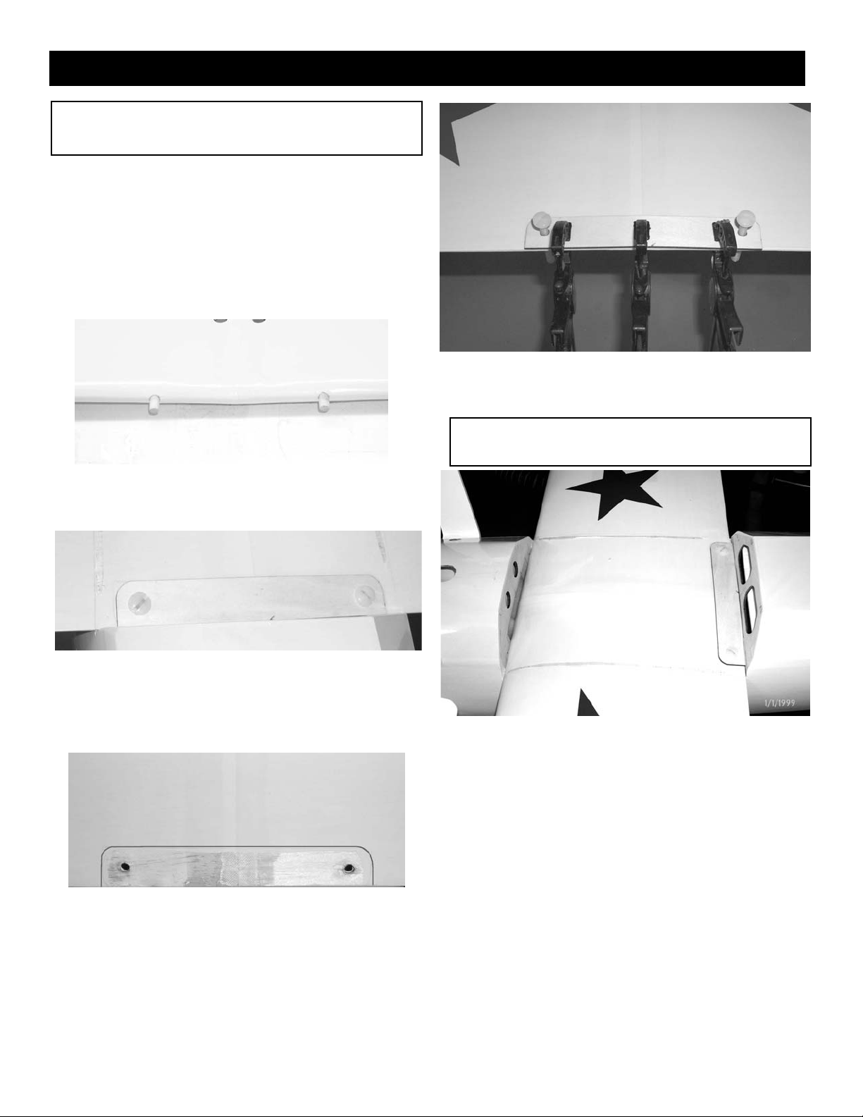
2. Take the 8 flat plates and bend in the
middle to about a 30 degree angle.
3.
Use the three 2-56 x 1/2” screws with a
washer under the head, and mount the brackets to
the fin and stab with the aircraft nut on the bottom.
The brackets go on each side of the fin and stab
with one bolt holding two on. There is a predrilled
hole at each location. Hold up to a light to help locate
the hole under the covering.
4. The other two brackets mount to the bottom
of the fuselage using the #2x1/2” sheet metal
screws. Mount to the tailwheel mounting block just in
front of the tailwheel bracket.
Page 19

19
6. Loop the end of the cable back though the
brass tube.
Use pliers and crimp the brass tubing onto the
cable to secure it.
5. Insert the cable through the 1/16 OD x 1/4”
brass tubing.
Next thread the cable though the hole at the
end of the 2-56 threaded rods and pass it back
through the brass tube.
7. Screw a golden clevis on the rigging coupler.
and attach it to the bracket at the fin.
Pull the cable to the bracket on the stab and
cut 2” past the hole.
6. After all four flying wires are in place, adjust
the tension by disconnecting the clevis and
turning.
8. Pass the cable through the brass tube,
through the bracket on the stab and back
through the brass tube.
Pull the cable tight, but be careful not to put
pressure on the stab or fin. we want the cable
to just be snug at this point and we will adjust
the tension after all four are in place.
Loop the cable back through the brass tube
again and crimp.
Use pliers and crimp the brass tubing onto the
cable to secure it.
8.
Pass the cable through the brass tube, through
the bracket on the stab and back through the
brass tube. Pull the cable tight, but be careful
not to put pressure on the stab or fin. we want
the cable to just be snug at this point and we
will adjust the tension after all four are in place.
Loop the cable back through the brass tube
again and crimp.
Repeat for the other four cables.
The wires should just be snug with no slop,
don’t distort the flying surfaces with
too much tension.
Page 20

20
Belly pan
1. Mount the bottom wing in place.
2. Place belly pan in place and mark the outline
on the bottom of wing.
3. Remove belly pan and cut the covering away
1/16” inside the line you drew.
Do not cut the wood!
4. Glue the belly pan in place using epoxy. Be
careful not to get glue on the front or rear, just glue to
wing, so the wing will come off.
remove covering
5. Remove the covering over the wing mount
bolts access hole.
remove covering
NO GLUE
Page 21

21
Engine Mounting
1. Collect the following items.
(2) motor mounts
(4) 8-32x1” bolts
(4) 8-32x1-1/4” bolts
(4) 8-32 t-nuts
(4) 8-32 aircraft lock nuts
(12) #8 flat washers.
2. Also collect the cowl mount bolts
(4) 4-40 x 1” socket head screws
(4) #4 flat washers
(4) 1/4” long pieces of silicone tubing.
3. Install the flat washer and silicone tubing on
the 4-40 bolts.
4. Install the cowl with the 4-40 bolts and the
predrilled holes in cowl. The blind nut are already
installed in the fuselage.
5
Measure from the firewall to the front edge of
the cowl.It should be about 5-3/8” on the left side and
5-5/8” on the right side. The difference is the off set
for right thrust built into the firewall.
6. Take your engine and clamp to one of the
motor mounts. Set the distance from the back of the
motor mount to the front of the thrust washer at 6”.
Page 22

22
7. Take the other motor mount and clamp to the
other side of the engine. Set the motor mounts on a
flat surface and make sure both sit flat on the table.
Make sure the distance from the table to the thrust
washer is at least 6”. Mark the location of the engine
mounting holes on the motor mounts.
8
Drill four 5/32” holes in the motor mounts at the
location you marked.
9. Mount the engine to the mounts using the
four 8-32 x 1-1/4” socket head bolts with aircraft lock
nuts and washers.
6”
10. The firewall has the thrust line marked on it.
The center line is off set to the left to compensate for
the right thrust.
11.
Center the motor mounts on the thrust line
and mark the location of the mounting holes. Drill a
7/32” hole at the four places you marked. The 7/32”
hole will accept the shoulder on the t-nut.
12.
Using one of the 8-32 bolts and washers,
seat the blind nuts in the holes.
13. Bolt the engine in place using the 8-32 bolts
and washers. Use locktite on the bolts.
Page 23

23
Fuel Tank
1. Collect the following item
(1) fuel tank 500cc (16.91 oz.)
(1) rubber tank stopper
(1) clunk
(1) 3mm x 25mm screw
(1) cap washer large
(1) cap washer small
(2) 3mm x 40mm brass tube
(1) 3mm x 60mm brass tube
(1) silicone tube 4mm x 80mm
(3) silicone tube 5mm x 165mm
2. Insert the 3mm screw through the center hole
in the large washer, through the center hole in
the rubber washer against the large side, and
screw the small washer on the back side.
3. Insert the brass tubes through three of the
holes. They should be arranged so as the long
one will be on the right side of the plane and
the short one on the left side.
The tubes should extend out the front of the
cap 5/8”. Bend the long tube up at about a 20
degree angle. This should be adjusted so the
end of the tube almost touches the top of the
tank when installed.
4. Install the 4mm silicone tube to the short brass
tube and install the clunk to the other end of
the silicone tube. This is the fuel pickup and
must be free to “flop” around in the tank so it
can pick up fuel in any attitude.
5. Install the assembly into the tank so the vent
tube is turned up to the top of the tank and is
positioned on the right side of the tank. Tighten
the screw to expand the rubber cap. Don’t over
tighten or you could split the tank.
Top of tank
5. Attach the three pieces of 5mm tubing to the
three tank outlets. They are different colors so
you can tell which are the two vents and which
is the fuel pickup after the tank is installed.
Make a note of which color you attach to which
tube. The short brass with the clunk is the fuel
pickup and must go to the carburetor. One of
the long brass tubes is the vent and should go
to the pressure outlet on the muffler. The second vent can be used for filling the fuel tank but
will have to be plugged with a screw (Not
Included) so that the fuel will not run out.
Page 24

24
6. If you use a Y-S engine that pressurizes the
tank, you should wrap the tank with nylon strapping
tape to make sure the pressure does not split the
tank. You should also put a couple of pieces across
the cap to make sure it does not blow out.
8. Install the tank in the fuselage with the cap
aligned in the hole in the firewall. Use foam rubber
(not included) around the tank to hold it in place
7. Before installing the tank, drill a 1/4” hole in
the firewall for the throttle pushrod to exit. The position of the hole will depend on the engine you use.
Align the hole with the throttle arm on your engine.
Page 25

25
Cowl Mounting
1. Collect the following items.
(1) Cowl
(4) 4-40 x 1” Socket Head Bolt
(4) #4 Washer
(4) 1/4” pieces silicone tubing
(1) 4” x 12” Clear Plastic
2. Place the 4” x 12” plastic strip so that it is sit-
ting on top on the engine just past the cylinder
head.
Tape the plastic to the fuselage at the very end
with masking tape.
Mark a outline around the cylinder head and
you exhaust pipe.
Make a mark where the back of the plastic is
sitting on the fuselage.
Un-tape the plastic sheet from the fuselage
and cut out the plastic where you marked for
the engine.
2. Unscrew the engine from the motor mounts.
Place the cowl on the fuselage and fasten
using the 4-40 x 1” bolts and washers.
Re-tape the clear plastic sheet on the marks
that you made on the fuselage.
Make a mark where the cut out is on the cowl.
remove the cowl and cut out the openings.
NOTE: Start with small openings then slowly
increase the size till the cowl fits.
3. Use the same method to locate the holes for
the needle valve and any other openings you
need.
Servo Installation
1. Collect the following items.
(1) 8mm x 17” wooden dowel
(2) pieces of 1/2” shrink tubing
(1) 5/32” x 19” nylon tubing
(2) 2-56 x 7-1/2” pushrods threaded one end
(1) 2-56 x 6” pushrod threaded one end
(1) 2-56 x 20” pushrod threaded one end.
(1) remainder of pull-pull cable from flying
wires
(4) cable swages(brass tubing)
(4) 2-56 rigging couplers
(8) 2-56 golden clevis
(8) clevis clips
(1) pushrod connector
You will need 7 servos for the plane. we
recommend a standard servo on the throttle and 4
standard servos are ok for the ailerons. The elevator
and rudder needs a 100oz of more servo. We used the
Futuba S9151 which is 132 oz.
Page 26

26
1. Install the servos in the tray with the elevator
servo all the way against the right side of the plane.
For maximum throw you will need longer arms than
come with the radio. Dubro heavy duty horns work
fine. The long elevator horn is 1-3/8” long. The double
ended horn for the rudder is 2.305” long. Install the
elevator horn, then mount the rudder servo with the
horn installed so it will clear the elevator arm. This will
put it a little left of center. The throttle servo can then
be mounted on the left side of the plane. (Note: This
set up was for a four stroke engine. If you use a
different engine you may have to mount the servos differently). Mount the throttle servo so it is on
the same side as the arm on your engine. It does not
matter if the elevator servo is on the right or left.
2. Install the throttle EZ connector in one of the
arms that came with your servo.
3. Install a golden clevis on the end of the 2-56
x 20 pushrod. Insert the pushrod in the hole in
firewall that you drilled earlier. Slip the 5/32”
nylon tube over pushrod and cut to length. It
should extend out the hole in the firewall
about 1/4” and stop short of the servo by
about 2”. Connect the clevis to your engine
and insert the pushrod in the connector body.
4.
Glue the nylon tube in the hole where it exits
the firewall.
Adjust the throw on the servos after the radio
is installed.
1. Insert the cable through the 1/16 OD x 1/4”
brass tubing.
Next thread the cable though the hole at the
end of the 2-56 threaded rods and loop it back
through the brass tube.
Rudder pull pull
2. Loop the end of the cable back though the
brass tube.
Crimp the brass tube with pliers.
Page 27

27
3. Insert the 1/8” tubing into the rear cable exit
hole. Push the tubing while guiding it through the
fuselage.
4. Thread the 2-56 end of the cable into the tub-
ing and pull the tubing out the rear cable exit.
.
Finish pulling the rudder cables through the
fuselage.
Make sure that the cables are running between
the openings in the formers. Stretch the
cables past the rudder servo by 3” to 4” then
cut off excess cable.
5. Thread one 2-56 nut then a 2-56 golden
clevis onto the each end of the cable.
Connect the golden clevis to the rudder horn
bracket. Remember to insert the clevis clip on
each of the clips.
6.
Repeat for the other rudder cable.
7. Assemble the 2-56 cable end same as shown
above.
8. Place the cable ends on your servo arm and
mount the servo arm on the rudder servo.
Tape your rudder with masking tape so that it
will remain straight.
.
Place the brass tube on the cable then pull the
cables through the holes in the threaded rod.
Pulling the cable tight, finish assembling the
cable just like you did before.
Do the same to the other cable.
You can tighten or loosen the finished cable by
twisting the golden clevis.
Lock the cable down after adjusting by
tightening the #2 nut against the clevis.
Page 28

28
Elevator Pushrod
1. Collect the following items
(1) 8mm x 17” wooden dowel
(2) 1/2” shrink tubing
(2) 2-56 x 7-1/2” pushrods threaded one end
(1) 2-56x 6” pushrod threaded one end
(3) 2-56 golden clevis
(3) 2-56 nuts
(3) clevis keepers
3. Take the 8mm dowel and drill a .073 (5/64”)
hole one inch from the end. Cut a slot from
the hole to the end of the dowel using a knife
or dremel tool. The slot should be the size of
the wire. Do this on both sides of the dowel.
Insert the end of the pushrod wire you bent
into the hole, one on each side. Use CA glue
to make sure they are firmly held.
2. Take the two 2-56 x 7-1/2” pushrods and
make a 90 degree bend on the unthreaded
end. Make the bend about 1/2” long so you
can get a good grip with the pliers. Then cut
the end off at 1/8”.
4. Take the shrink tubing and slide over the end
of the dowel and wires. Let the tubing extend
past the end of the dowel about 1/4”. Use a
heat gun to shrink tight. If you don’t have a
heat gun a match or lighter will work just be
careful with the open flame.
5. Lay the pushrod on the bottom of the fuse
lage and spread the two pushrods apart the
distance of the control horns on the elevators.
Don’t make sharp bends, let the pushrods
bow out to the horns. This will give you a tight
pushrod set up with no flex.
6.
Put the pushrod in the fuselage fishing the
rods out the slot on each side. Install the
clevis and hook up the clevis to the control
horn. Use masking tape to hold the elevators
in neutral while you mark the other end.
Mark here
Page 29

29
7. Install a clevis on the 6” pushrod and attach
to elevator arm on servo. Make a mark on the rod
and the dowel where they cross 1” from the end of
the dowel.
Remove the clevis from the arm and make a
90 degree bend at the mark. Cut the bend at 1/4”.
Remove the clevises from the elevator horns
and remove the pushrod from the fuselage. Drill a
.073(5/64”) hole at the mark you made and cut a slot
for the pushrod just as we did on the other end.
Attach the pushrod using CA and the shrink tube.
8. You now have a finished pushrod. Reinstall in
fuselage using the #2 nuts on the pushrod then the
clevis. After all adjustments are made the #2 nut will
be tightened against the clevis to prevent it from
vibrating loose. Install the clevis keepers.
1. Install the switch in the side of the fuselage
on the opposite side from the engine exhaust.
2.
The battery will need to be mounted accord-
ing to where your weight and balance comes out.
Ours needed to be under the servos to get the
weight to the rear. After you complete the model
decide where the best place is depending on the
engine you use.
3
There are tons of room between the servo tray
and the tank, so mount the receiver there.
Switch,Receiver,Battery
Balance and Control Throws
Throws
We have provided two sets of throws.
Use the lower throws on the first flights
then work your way up to the higher
throws. Do not use the higher throws till
you are ready.
LOW HIGH
Elevator 1” UP& Down All you can get
Ailerons 1/2” Up & Down All you can get
Rudder 1-1/2” Right & Left All you can get
When you have gotten comfortable
flying the Pitts slowly increase the throws
while still staying within your flying ability.
The Pitts was designed around a
1.20 four-cycle engine or a .90 two-cycle
engine both of these engines will give you
excellent performance. Remember, a bigger engine is not always better. Using a
15-8 to a 16-8 prop works well on these
engines.
Most any size spinner will work on
the Pitts, but a 3” is the right proportion
for the airplane.
The receiver should be wrapped in at least 1” of
foam rubber. You will need two Y-connectors here.
Plug one into the receiver, the other y-connector will
plug into one terminal for the bottom wing servos and
the other terminal will go to the y-connector we
installed in the fuselage for the top wing servos. Route
the antenna out the side of the fuselage and attach to
the top of the fin using a rubber band and a straight
pin.
Page 30

30
CG Balancing
Balancing the Pitts is very important, you might need to use weight depending
on the servos and engine that you use. Start out with the balance point at 5”. This
balance point is a safe place for you to fly the Pitts.. As you get comfortable you can
move the CG back further. The 33% point is 6.22” The further back you move the CG
the more wild the aerobatics will become, BUT the more unstable the Pitts will become
The CG is measured on the top wing At the center of the wing measure back 5” and
place a mark. Measure back 6.2” and make another mark. Using two fingers under the
bottom side of the top wing, lift the plane. It should hang level or slightly nose down. At
the 5” in mark it will be nose heavy but will be really stable on the first flight. The Pitts
will probably need weight in the tail to get it back to 6.22”.
©Copyright 2004 Carl Goldberg Products
 Loading...