

Carl Goldberg GBGA1087 User Manual
1
WARNING
A radio-controlled model is not a toy and is not intended for persons under 16 years old. Keep
this kit out of the reach of younger children, as it contains parts that could be dangerous. A radiocontrolled model is capable of causing serious bodily injury and property damage. It is the buyer's
responsibility to assemble this aircraft correctly and to properly install the motor, radio, and all other
equipment. Test and fly the finished model only in the presence and with the assistance of another
experienced R/C flyer. The model must always be operated and flown using great care and common
sense, as well as in accordance with the Safety Code of the Academy of Model Aeronautics (5151
Memorial Drive, Muncie, IN 47302, 1-800-435-9262). We suggest you join the AMA and become properly insured prior to flying this model. Also, consult with the AMA or your local hobby dealer to find an
experienced instructor in your area. Per the Federal Communications Commission, you are required
to use only those radio frequencies specified "for Model Aircraft."
LIMITED WARRANTY
Carl Goldberg Products, Ltd. has inspected and certified the components of this aircraft. The company urges the buyer to perform
his own inspection, prior to assembly, and to immediately request a replacement of any parts he believes to be defective for their
intended use. The company warrants replacement of any such components, provided the buyer requests such replacement within a period of 30 days from the date of purchase and provided the defective part is returned, if so requested by the company.
No other warranty, expressed or implied, is made by the company with respect to this kit. The buyer acknowledges and understands that it is his responsibility to carefully assemble the finished flying model airplane and to fly it safely. The buyer hereby
assumes full responsibility for the risk and all liability for personal or property damage or injury arising out of the buyer's use of the
components of this kit.
CARL GOLDBERG PRODUCTS, LT
P.O. Box 88 Oakwood GA 30566 Phone #678-450-0085 Fax # 770-532-2163 www.carlgoldbergproducts.com
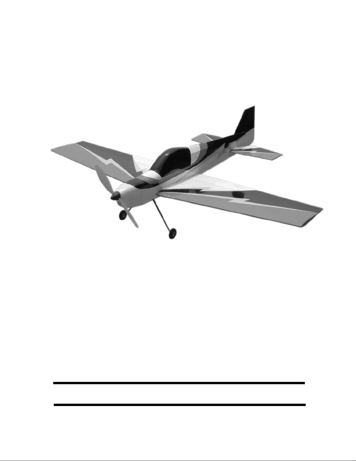
SHOCK 3D
SHOCK 3D
ARF
ARF
© Copyright Carl Goldberg Products,Ltd.2004

2
USING THIS INSTRUCTION MANUAL
Before you begin assembling your Shock 3D ARF, take
some time to read through this entire instruction book. It is
designed to take you step-by-step through the process and
to give you added information on motor and radio selection
and set-up, balancing your aircraft, and flying your model.
The time you spend will speed the assembly process and
help you avoid problems.
PREPARING FOR ASSEMBLY
You will need a work area of approximately 24 x 48" which has
been covered to protect it from adhesive, as well as cuts and
other damage. Many people cover their work area with a
sheet of dry wall (sheet rock) and/or waxed paper t o prevent CA Glue and Epoxy from ruining the work surface.
CONSTRUCTION TIPS
IMPORTANT: ALWAYS READ A FEW STEPS AHEAD.
This will alert you to coming instructions and will help you
plan accordingly.
Using the Parts Identification section, familiarize yourself
with the various items included in your kit box.
Do not hesitate to ask questions. Your local hobby dealer
and area flyers will most likely be happy to help, as they
want you to have a successful flying experience.
You may also receive technical assistance from Carl
Goldberg Products, Ltd. via e-mail (questions@carlgoldbergproducts.com) or by telephone 1-678-450-0085.
ADHESIVES & GLUING TECHNIQUES
CA adhesives are specially formulated to firmly glue the
plywood, hardwood, and balsa used in your model and to
withstand the vibration and stresses of high performance
flight. However, there are times, such as when you are
installing the stabilizer and fin on the fuselage and want
more set-up time for careful alignment and positioning,
then you should use epoxy. Occasionally, you also will
want to use thin CA, which "wicks" into the surrounding
areas. Aliphatic resin glue or similar water-based glues can
also be used, but they will add to the assembly time
because they dry so much more slowly than CA glue.
Remember, when ever using any CA, you must be careful
to read instructions thoroughly, as you will have only seconds for positioning of parts. Be sure to trial fit parts
together before gluing. Also, never use watery THIN type
CA glue for gluing plywood and hardwood parts. Thin CA's
do not adequately bond these areas.
CAUTION
Some people may experience an allergic reaction when
exposed to fumes from CA glue or epoxy. As with paints,
thinners, and solvents, it is always important to use glues
only where there is adequate ventilation to carry fumes
away. A fan is recommended. Also, special care must be
taken when using CA, as it will bond skin as well as other
surfaces. Before using any CA, carefully read all label precautions. When using CA, protective eye-wear and care in
keeping the glue away from the face is highly recommended. If CA does happen to get into the eye, hold lid open
and flush with water only. Seek immediate medical attention.
COVERING
The Shock 3D ARF is covered in a premium polyester film
chosen by many of the world's top flyers for its beauty,
toughness, and ease of application and repair. It is not
uncommon for ARF's to develop a few wrinkles in transit.
If this is true of your model, the situation is easily corrected. Before you begin putting the pieces together, run
around the edge of the seams first then over the surface of
each section with an iron (either specially designed for airplane use or the more cumbersome household iron).
Apply the heat (set at about 350° F), following along with a
soft cloth and pressing down on the covering as you go
around. This will more firmly set the covering adhesive into
the wood and keep your aircraft covering tight and smooth
in the future. Once you have ironed the seams stay away
from them with the heat or the covering will slide when you
try to shrink the middle. If this happens the wrinkles will not
come out of the covering.
One of the great advantages of polyester film is that it can
be applied over itself without causing gas bubbles. This
allows you to repair your aircraft, as well as to customize it
in a number of ways. If, due to a flight mishap, you get a
hole or similar covering damage, simply trim away the
ragged edges and then apply a patch, following the directions that come with your covering , which is available at
your hobby dealer.
The Shock 3D covering can be matched using
Oracover Black 874
Oracover White 870
Oracover Yellow 872
Oracover Red 883

3
ITEMS NEEDED TO COMPLETE THIS AIRCRAFT
1 RADIO GUIDANCE SYSTEM (4 CHANNEL
MINIMUM REQUIRED WITH 4 SERVOS)
1 6” SERVO “Y” HARNESS
1 ELECTRONIC SPEED CONTROL
(ELECTRIC FLY C-20 FROM GREAT
PLANES SUGGESTED)
1 NIMH 7C 650AAA BATTERY (2 OR 3 CELL
2100 MAH LI-PO BATTERY SUGGESTED)
1 CA ACCELERATOR
1 1 OZ. BOTTLE CA MEDIUM GLUE
1 1/2 OZ. BOTTLE CA THIN GLUE
1 5 MINUET EPOXY
1 1/4” FOAM RUBBER
1 400 SIZE MOTOR OR BRUSHLESS
MOTOR EQUIVALENT
1 6 TO 1 GEAR DRIVE
TOOLS AND SUPPLIES FOR ASSEMBLY.
MODELING OR UTILITY KNIFE
WORK SURFACE (24" X48")
SMALL STANDARD & PHILLIPS SCREW-
DRIVERS
MASKING TAPE
NEEDLE NOSE PLIERS
24” RULER
FLEXIBLE STRAIGHT-EDGE
30-60-90° x 6" TRIANGLE
SOFT PENCIL
A FEW STRAIGHT OR "T" PINS
WIRE CUTTER (DYKES)
OPTIONAL HEAT GUN/COVERING IRON
ACID BRUSH
5 FT. LENGTH OF STRING
Caution:
Before starting, care-
fully go over all high
stress areas with an
epoxy or wood glue to
confirm all areas are
well glued.
Important
Information
Covering coming loose is not
COVERED UNDER WARRANTY. Due to temperature changes the plane may develop
some wrinkles in the covering that you will
need to remove with an iron. Be sure to seal
the edges down first so that you do not
cause the covering to shrink and leave
exposed areas of wood. Please inspect the
plane before beginning to assemble to make
sure you are happy with it. After assembly
has begun you cannot return the kit. If you
find a problem before beginning to assemble
the plane you must contact us, please do
not return it to the dealer.
4
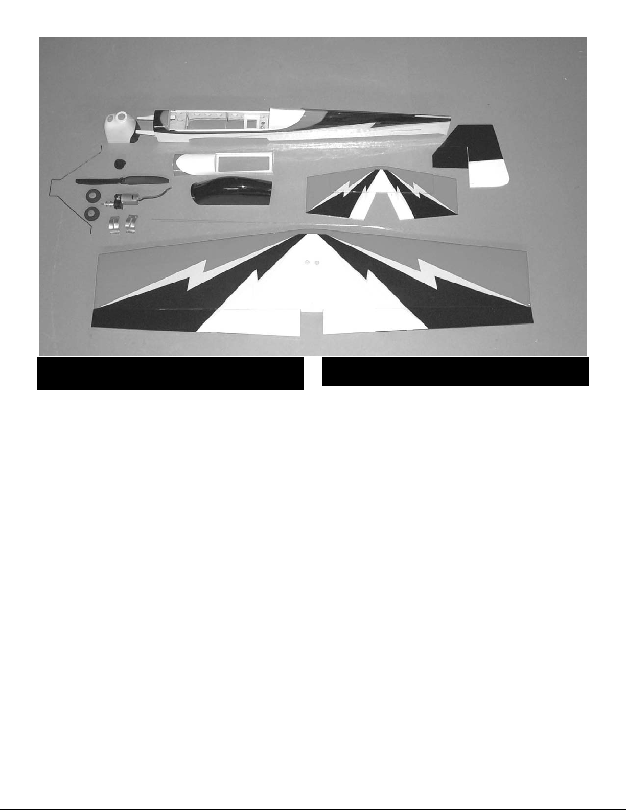
1. Fuselage
2. Wing with Ailerons
3. Stab with Elevators
4. Fin
5. Rudder
6. Canopy
7. Hatch Cover
8. Cowl
9. Landing Gear
10. (2) Wheels
11. Prop (not included)
12. Spinner(not included)
13. Motor with Gear Drive(not included)
14. Motor mounts(not included)
Parts List
(Shown Above)
Hardware
(Not Shown)
Wing
(2) laser cut control horns
(2) nylon swing in keepers
(2) 1/32 x 5-1/2” pushrods
(1) 4-40 x 3/4” socket head bolt
(1) #4 flat washer
(2) Pushrod connectors
Stab and Rudder
(2) laser cut control horns
(1) elevator joiner wire
(7) CA hinges
(2) nylon swing in keepers
(2) pushrod connectors
(2) 1/32 x 24” pushrods
Landing Gear
(1) Main landing gear
(2) wheels
(2) plastic wheel retainers
(1) tail skid wire
(1) landing gear cover plate
Motor Mount
(1) 3/8” square spruce optional motor mount
Cowl Mounting
(2) plated #2 x 1/4 screws
(2) black #2 x 1/4 screws
5
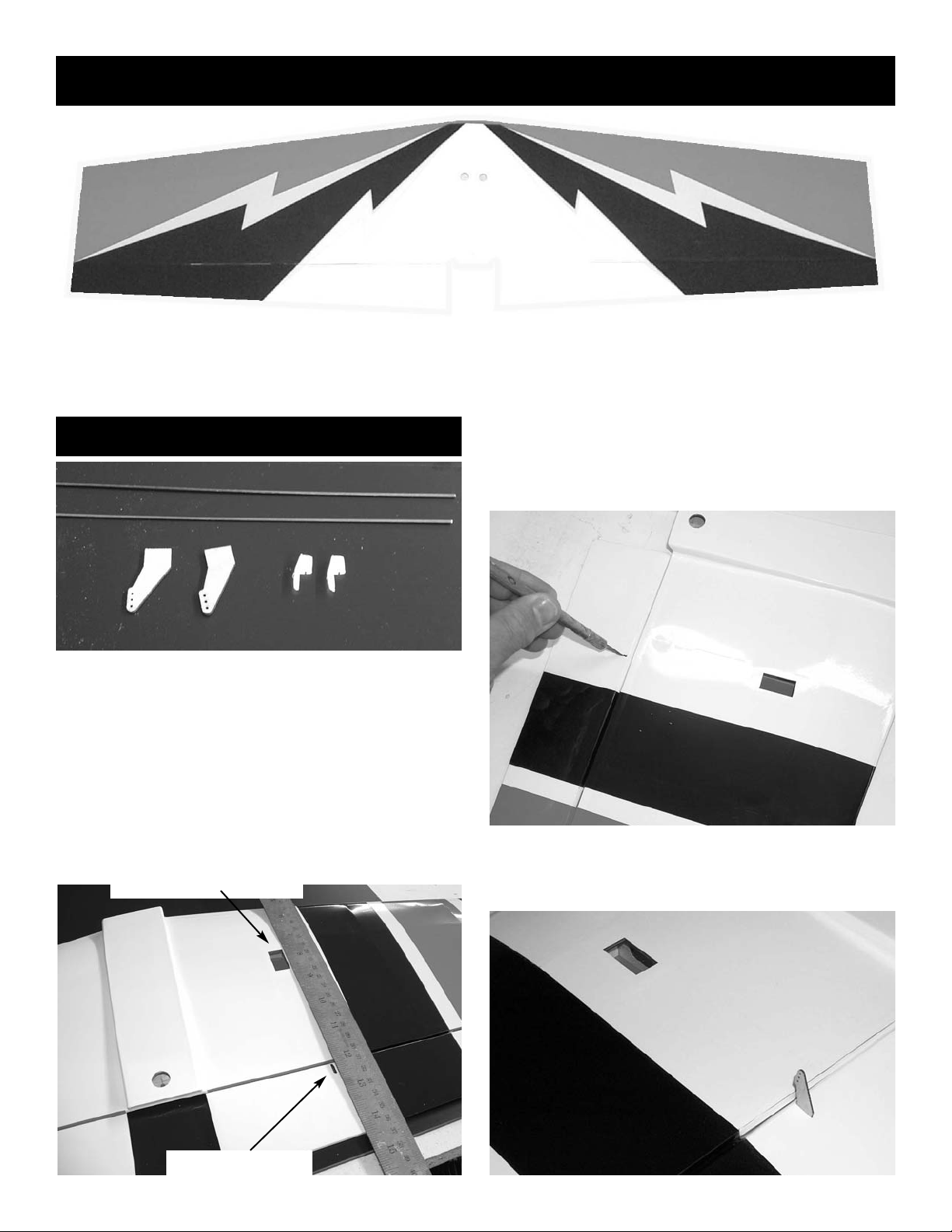
Wing
The wing for the Shock 3D comes pre-assembled with the ailerons already hinged. All that is
required to finish the wing is to install the aileron servos, control horns and attach the pushrods.
AILERON SERVO INSTALLATION
1. Collect the following parts:
(2) servos with mounting hardware(not supplied)
(1) 6” y-connector(not supplied)
(1) piece of string, soft wire, or cable tie(not sup-
plied)
(2) laser cut control horns
(2) 1/32” x 5-1/2” wire pushrods
(2) mini pushrod connectors
aileron servo cutout
control horn slot
2. Locate the control horn slot by laying a straight
edge along the outside edge on the servo
opening. The slot is pre-cut in the aileron but
is covered over with the film.
3. Use an X-acto knife or razor blade and remove
the covering over the control horn opening.
Do this on both sides of the aileron.
 Loading...