

Page 1
CCAARRLL GGOOLLDDBBEERRGG PPRROODDUUCCTTSS LLTTDD..CCAARR
P.O. Box 818, Oakwood, GA 30566 • 678-450-0085 • Fax: 770-532-2163 • www.carlgoldbergproducts.com P.O.
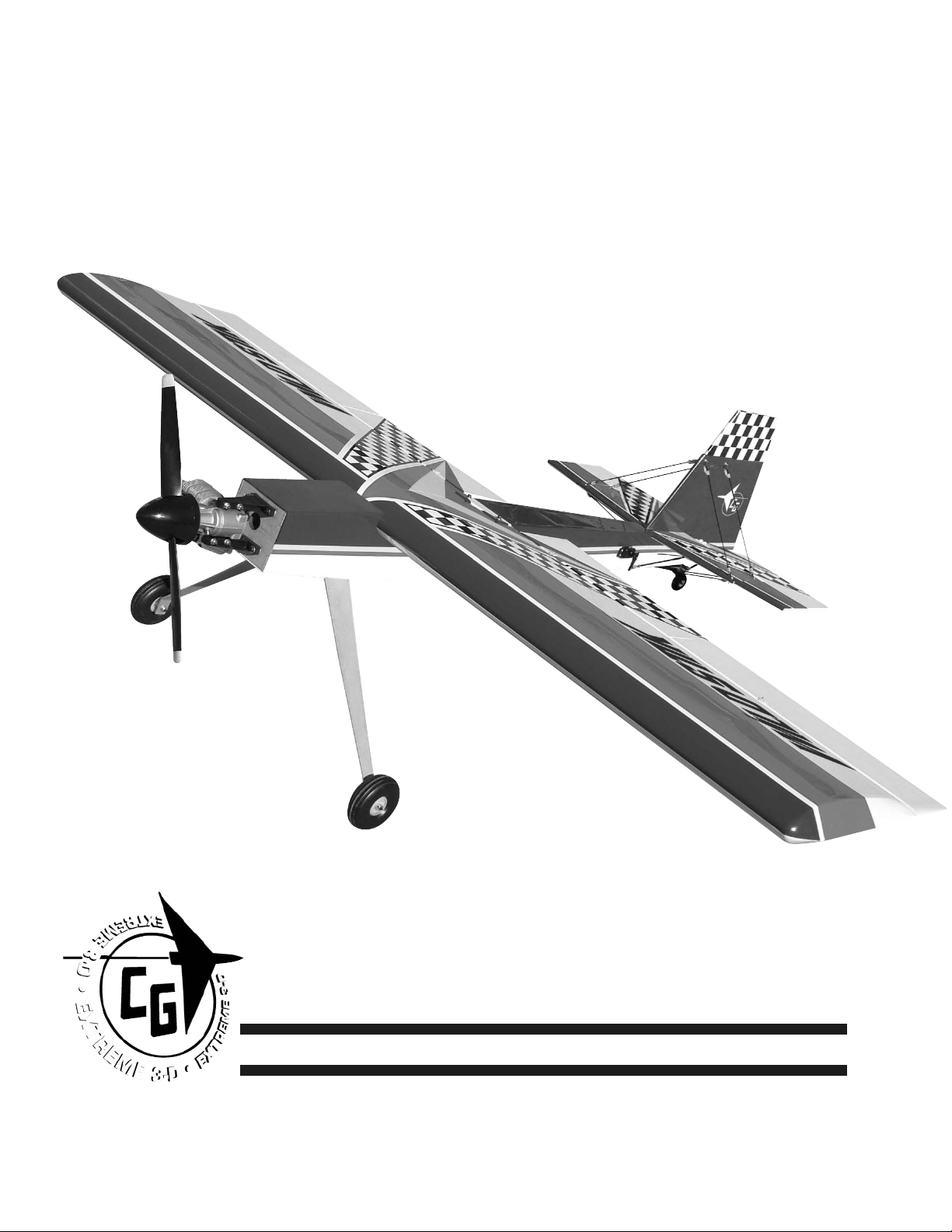
Wild Stick 120
Wild Stick 120
©copyright 2004 Carl Goldberg Products.
Page 2

2
Wild Stick 120
WARNING! THIS IS NOT A TOY!
THIS IS NOT A BEGINNERS AIRPLANE
This R/C kit and the model you will build from it is not a toy! It is capable of
serious bodily harm and property damage. It is your responsibility, and yours
alone - to build this kit correctly, properly install all R/C components and
flying gear (engine, tank, radio, pushrods, etc. and to test the model and fly
it only with experienced, competent help, using common sense and in accordance with all safety standards as set forth in the Academy of Model
Aeronautics Safety Code. It is suggested that you join the AMA and become
properly insured before attempting to fly this model. If you are just starting
R/C modeling, consult your local hobby dealer or write to the Academy of
Model Aeronautics to find an experienced instructor in your area.
Write to: Academy of Model Aeronautics, 5151 Memorial Dr. Muncie, IN
47302
LIMITED WARRANTY
Carl Goldberg Products is proud of the care and attention that goes into
the manufacture of parts for its model kits. The company warrants that for
a period of 90 days, it will replace, at the buyers request, any part or material shown to the company's satisfaction to have been defective in workmanship or material at the time of purchase.
No other warranty of any kind, expressed or implied, is made with respect to
the merchandise sold by the company. The buyer acknowledges and understands that he is purchasing only a component kit from which the buyer will
himself construct a finished flying model airplane. The company is neither
the manufacturer of such a flying model airplane, nor a seller of it. The
buyer hereby assumes the risk and all liability for personal or property damage or injury arising out of the buyers use of the components or the finished
flying model airplane, whenever any such damage or injury shall occur.
Any action brought forth against the company, based on the breach of the
contract of sale to the buyer, or on any alleged warranty there under, must
be brought within one year of the date of such sale, or there after be
barred. This one-year limitation is imposed by agreement of the parties as permitted by the laws of the state of Georgia.
Important Information
Covering coming loose is not COVERED UNDER WARRANTY. Due to temperature changes the plane may develop some wrinkles in the covering that you
will need to remove with an iron. Be sure to seal the edges down first so that
you do not cause the covering to shrink and leave exposed areas of wood.
Please inspect the plane before beginning to assemble to make sure you are
happy with it. After assembly has begun you cannot return the kit. If you find
a problem before beginning to assemble the plane you must contact us,
please do not return it to the dealer.
Page 3

3
Wild Stick 120
Wild Stick
Wild Stick
Congratulations on your purchase of the Lanier Wild Stick 120. This is a very
unique aircraft, with great 3-D capabilities. Every effort has been made to
produce a lightweight, straight, easy to assemble aircraft. Because of its
oversize control surfaces which are double beveled to allow for extreme
throws, great care must be taken in the set-up and flying of this airplane.
Quality hardware components have been provided to allow for 3D set-up
while maintaining adequate mechanical advantage to eliminate flutter. It is
you responsibility as an advanced pilot to fly the aircraft in an intelligent
manner. THROTTLE MANAGEMENT IS A MUST!!!!!!!! We at Lanier have put the
Wild Stick 120 through a very rigorous flight-testing schedule and have
stressed the airframe beyond all practical parameters without a single failure. Lanier will NOT warrant the Wild Stick 120against flutter due to improper set-up or excessive speed maneuvers. having said that, we believe you will
find the Wild Stick 120 to be one of the most responsive, in-the-grove aircraft
on the market. The Wild Stick 120 excels at high-alpha maneuvers including
Harriers (both upright and inverted), high-alpha rolls, and high-alpha knife
edge. Torque rolls, waterfalls, knife edge loops and elevators are all within
the performance parameters of this unique aircraft. Just remember to use
common sense when flying this high performance machine.
Page 4
4
Wild Stick 120
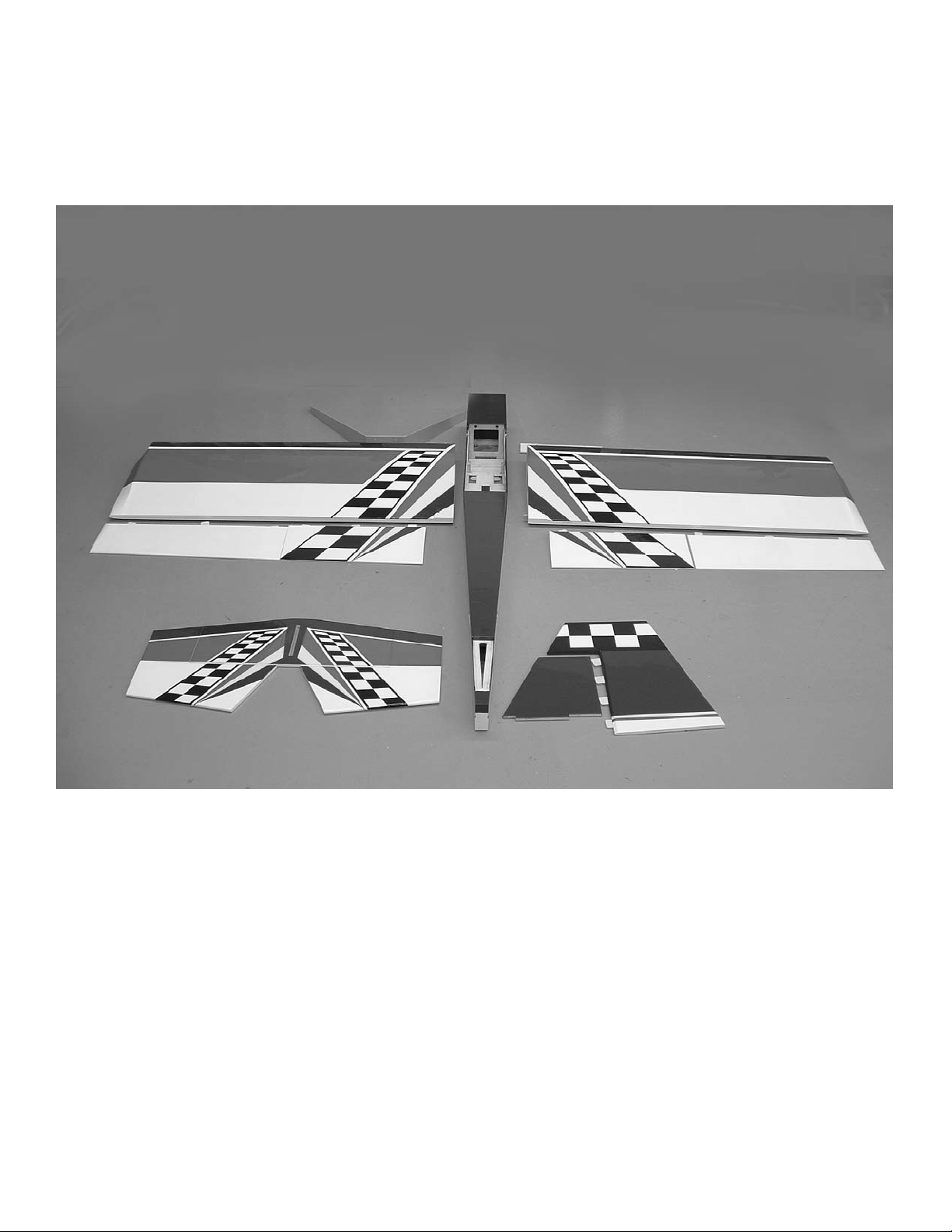
Parts Layout
Fuselage 1
wing panels 2
ailerons 2
Flaps 2
Stabilizer 1
Elevators 2
Fin 1
Rudder 1
landing Gear 1
Colors
Red True red #866
White #870
Black #874
Blue Deep Blue #873
yellow Bright Yellow #872
Page 5

5
Wild Stick 120
Landing Gear 1
4mmx12mm bolts 4
4mm washers 6
4mm wheel collars 4
4mm axels 2
4mm lock nuts 2
3.5” wheels 2
Motor Mounts 2
4mmx20mm bolts 4
4mmx25mm bolts 4
4mm blind nuts 4
4mm flat washers 8
4mm lock nuts 4
Flying Wires
1.8mmx16mm bolts 6
1.8mm nuts 6
1.8mm washers 12
metal brackets 12
nylon swing in keepers 8
1.6mmx10” pushrod with clevis 4
1.6mmx7” pushrod with clevis 4
metal plate(bottom bracket) 1
silicone clevis keepers 8
2mmx10mm screws 2
Control horns 8
control horn plates 6
2mmx20mm screws 14
2mm nuts 2
Pushrods
3mmx10cm pushrods(aileron) 4
3mmx20cm pushrods(elevator) 2
3mm metal clevis 12
3mm jam nuts 12
Braided cable feet 6
Rigging couplers 2mm 4
cable swages 4
2mm clevises 5
2mm jam nuts 5
Silicone clevis keepers 17
2mmx50cm throttle pushrod 1
Pushrod connector(e-z connector)1
plastic tube 4mmx25cm 1
Hardware List
Wing bolts
4mmx40mm 2
4mm flat washers 2
Fuel tank with hardware 1
Tail wheel
Tail wheel bracket
metal rudder horn
spring wire axel
springs (2)
wheel collar
tiller arm bracket
threaded rod (tiller arm)
nylon pushrod ends (2)
2mm x 10mm screws (5)
flat washers (5)
Page 6
6
Wild Stick 120
BUILDING
INSTRUCTIONS
Before starting to build this kit, we
urge you to read through these
instructions. They contain some
important building sequences as well
as instructions and warnings concerning the assembly and use of the
model.
We expect that you have some building experience to take on this model.
However, every minute detail is not
covered. This is not a basic trainer.
The instructions together with the
simplicity of this kit will allow you to
produce a first class Wild Stick 3-D.
BUILDING SUPPLIES NEEDED
Hobby knife w/ #11 blade
Thin Zap CA
30 Minute Z-poxy
Thread lock
Wire cutters
Pliers
Drill with bits: 1/8", 5/32", 1/16”
5/64”
Phillips and standard screwdriver
Small clamps
Masking tape
Tape measure
Washable marker
Paper towels
Rubbing alcohol
Wing Construction
Collect the following parts:
1. left and right wing panel
2. dihedral brace
3. wing holddown bolts(2)
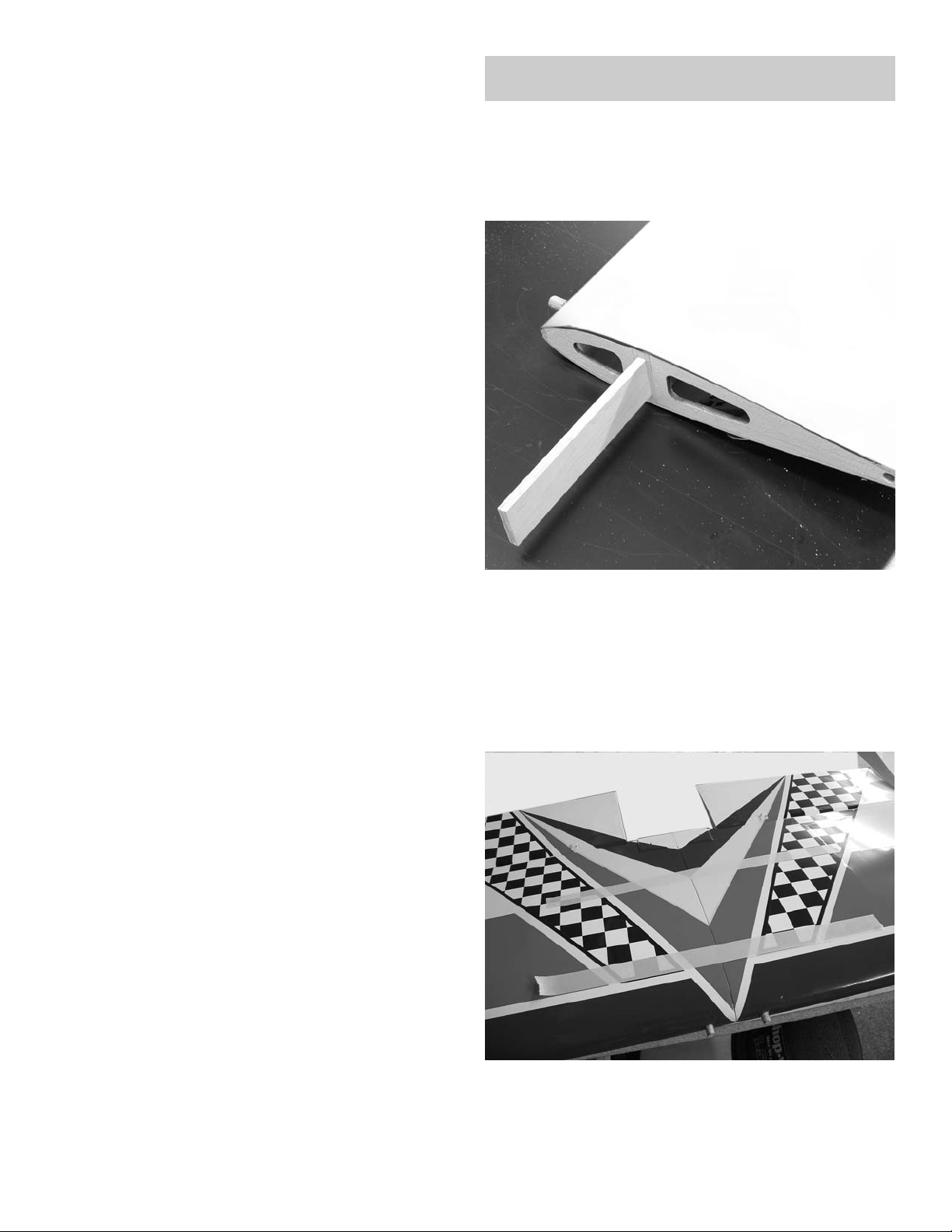
1. Trial fit the dihedral brace in the
slot on one wing. The wing is flat (no
dihedral) so the brace should fit
either way. Slide the other wing
panel in place and make sure the
joint in the center is closed.
2. Mix some 30 minute epoxy and
spread on all sides of the dihedral
brace, front back and edges.
Page 7
7
Wild Stick 120
3. Spread epoxy on the root rib of
each wing panel. Use a thin scrap of
wood and work some of the epoxy
down into the slots for the dihedral
brace on each panel.
4. Use masking tape to hold the wing
panels firmly together while the
epoxy set. Lay the wing flat on the
floor or work bench while the epoxy
cures. Do not stand the wing on one
tip, all the glue will run to one end
and give you a poor joint.
5. locate the two 4mm x 40mm bolts
and two 4mm flat washers.
6. After the epoxy has cured, bolt the
wing in place on the fuselage..
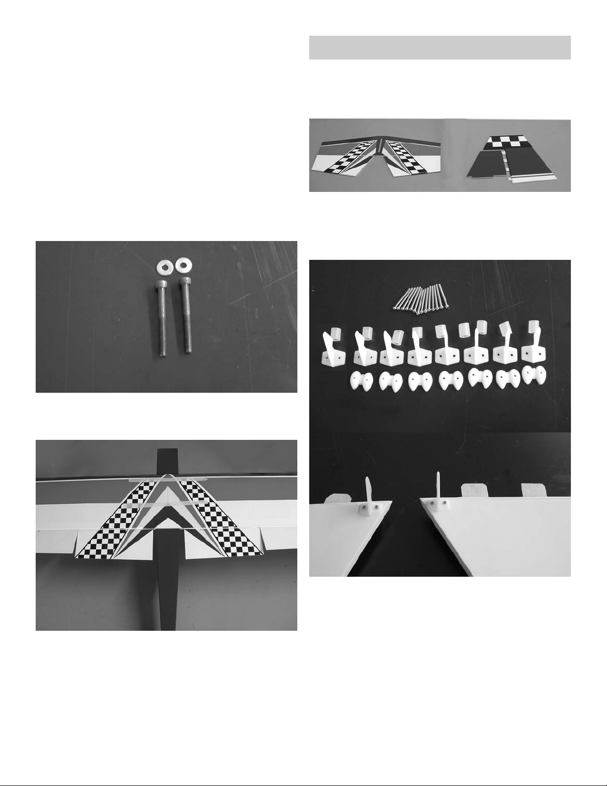
Tail construction
locate the following parts;
1. stabilizer with elevators
2. Fin with rudder
3. Nylon control horns
4. nylon nut plates
5. 2mm x 20mm screws
6. Silicone clevis keepers
1. locate the control horns on the
inside edge of the elevators on the
bottom side. make sure the holes for
the clevis are aligned over the hinge
line. Mark the location of the holes
and drill a 3/32” hole at the four
locations. use the 2mm screws and
nut plates to mount the control
horns.
Page 8
8
Wild Stick 120
Align holes over
hinge line
2. Remove the elevators from the
stab and make sure all the hinges are
centered in the slots. To make sure
the hinges are centered, use a
straight pin in the middle of the hinge
when pushing the elevator onto the
stab.
3. Flex the elevator to the full
extent of its travel in one direction.
make sure the hinge line stays closed
as close as possible. Apply a drop of
thin CA to each hinge. Turn the stab
over, flex the elevator to the full
travel in the other direction and
apply glue to each hinge. go back and
apply another drop of glue to each
hinge.
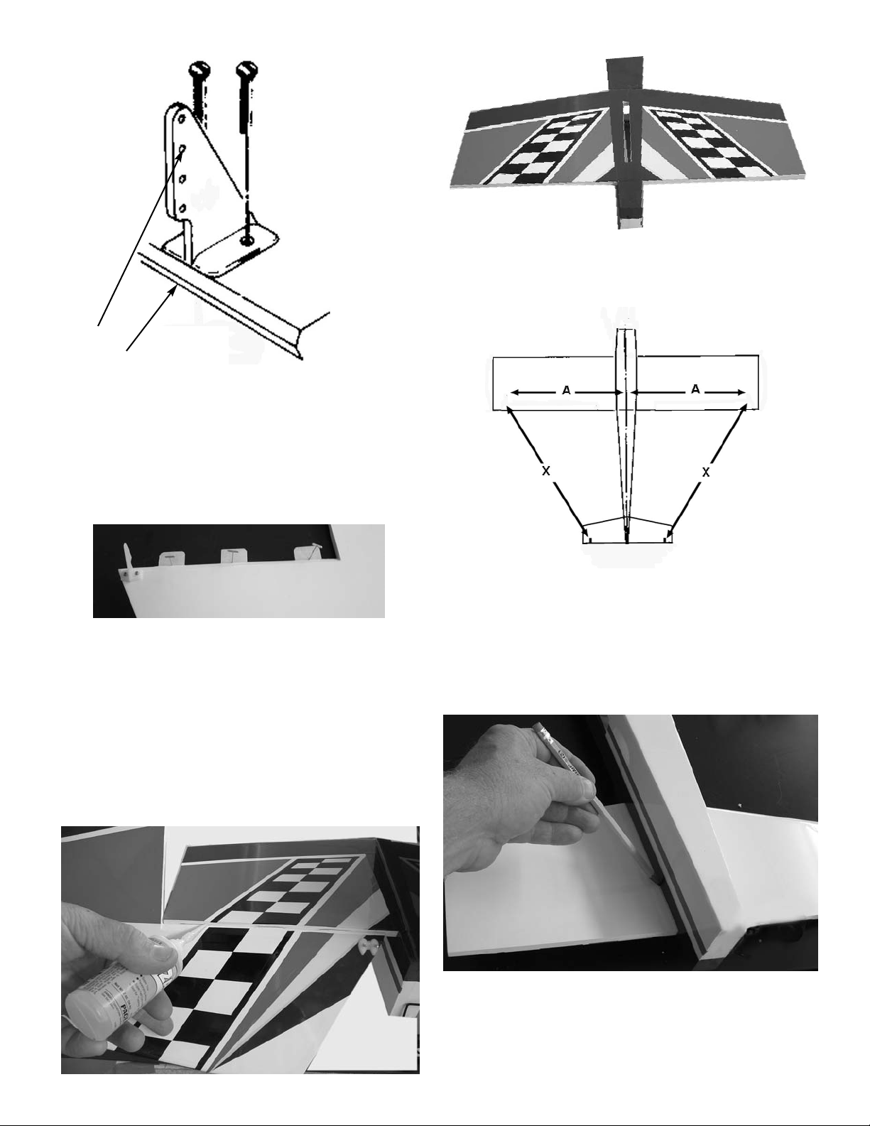
4. Set the stab in place in the slot on
the rear of the fuselage.
5. measure the stab to make sure it is
centered in the fuselage. Make sure
the slot for the fin in centered on
the fuselage. Move the stab until
dimension X-X are the same. This will
have the stab square to the fuselage.
6. When you have the stab square to
the fuselage, make a mark along the
side of the fuselage on the bottom of
the stab.
Page 9

9
Wild Stick 120
7. use a razor blade or e-xacto knife
to carefully remove the covering
inside the marks on the bottom of the
stab. Cut carefully so as not to cut
the wood, just the covering.
8. mix some 30 minute epoxy and apply
to the bare wood on the bottom of
the stab and in the slot on the rear
of the fuse. Reinstall the stab and
check to make sure it is square. use
pins to hold in place. Check the
alignment with the wing by sighting
from the front and rear. Apply pressure to one side if necessary to make
stab parallel to wing.
remove covering
9. Remove the covering from the bottom portion of the rudder where it
plugs into the stab.
remove covering
10. Fit the fin in place and make a
mark around it. Remove the covering
inside the marks on both the stab and
the rear portion of the fuselage
behind the stab.
Page 10

10
Wild Stick 120
11. Epoxy the fin in place making sure
it is square to the stab and centered
on the fuselage in the rear.
Flying Wires
Locate the following parts:
Aluminum bracket for fuse bottom 1
2mmx10mm screws 2
angle brackets 12
1.8x16mm bolts 6
1.8mm nuts 6
flat washers 12
nylon swing in keepers 8
2mm pushrods with clevis x 10” 4
2mm pushrods with clevis x 7” 4
silicone clevis keepers 8
1.Take four of the angle brackets, two
screws, two nuts and four flat washers and bolt to the top of the fin in
the predrilled holes. You will have to
locate the holes under the covering.
Put two brackets on each side of the
fin.
2.Repeat with the other brackets on
the end of the stab. Put brackets on
both sides top and bottom.
Page 11

11
Wild Stick 120
3.Mount the aluminum bracket on the
bottom of the fuselage using the two
2mmx10mm screws.
Use the tail wheel bracket to align
the flying wire bracket at the front
edge of the mounting block. Align the
tail wheel bracket at the rear edge
of the fuselage and mount the aluminum bracket at the front edge.
Page 12

12
Wild Stick 120
4.Take one of the 7” pushrods and
make sure the clevis is screwed on
with about 1/16” of threads showing
on the inside. Install the clevis on the
angle bracket and mark the location
over the hole on the fuselage bracket. Make a 90 degree bend and cut at
3/8”. install the wire in the aluminum
fuse bracket and retain with the
nylon swing in keeper. Adjust the
length so you don’t pull the stab out
of alignment.
5.Repeat for all four wires on the bottom side.
6.Take the 10” pushrods and attach to
brackets on stab. Bend 90 degrees at
brackets on fin and cut to 3/8”.
Retain with nylon swing in keepers.
Repeat for other side.
7.After all wires are installed they
can be adjusted by putting a level in
the center of the stab and leveling
the plane. Move the level to the tip of
the stab and adjust wires till level.
Page 13

13
Wild Stick 120
1. Fit the landing gear to the bottom
of the fuselage and install the four
screws and flat washers. Use locktit
on the screws.
2. install the axels using the aircraft
lock nuts.
3. install the wheels using one wheel
collar on the inside and one on the
outside of the wheel.
locate the following parts:
1. landing gear
2. Two wheels
3. Two axels
4. two axel nuts
5. Four wheel collars
6. Six flat washers
7. Four mm screws
landing Gear
Page 14

14
Wild Stick 120
Tail wheel
Locate the following Parts:
Tail wheel bracket
tail wheel
rudder tiller arm
wire axel
3mm wheel collar
nylon control horn brackets 2
springs 2
tail wheel tiller arm
tail wheel tiller arm collar
2mm screws 5
2mm washers 5
1. Insert the tail wheel wire into the
bracket and fit the collar on
top.align the hole for the tiller arm
so it is parallel to the axel.
2. Center the tiller arm in the collar
and tighten the set screw. Screw the
nylon horn brackets on each end.
Install the tail wheel using the 3mm
collar to retain.
3. Mount the bracket flush with the
rear of the fuselage using the three
screws.
Page 15

15
Wild Stick 120
Engine Installation
locate the following parts:
1. Two motor mounts
2. Four 4mmx20mm screws
3. Four 4mm blind nuts
4. Four 4mmx25mm bolts
5. Four 4mm aircraft lock nuts.
6. 8 4mm flat washers
1. Clamp your engine to the two
motor mount making sure that both
sides of the mounts sit squarely on
the table. Make sure the engine is not
offset to the left or right in the
mount. Mark the location of the four
holes.
2. Drill four holes and mount the
engine using the four 4mm bolts and
aircraft lock nuts.
4. Attach the two springs to the
tiller on one end and the two nylon
horn brackets on the other. Pull the
bracket along the bottom of the rudder until the springs have a little
tension on them. Mount the bracket
at this point. Drill two holes with a
#54 drill and harden the holes with
thin CA. Mount the bracket with the
two 2mmx1mm screws and flat washers.
Page 16

16
Wild Stick 120
3. Center the engine on the firewall
and mark the location of the four
mounting bolts.
4. install the four blind nuts in the
firewall. The best way to install the
nuts is to use a piece of wire to pull
the nuts into place .
5. pull the nuts up with the wire then
install the bolt and washer through
the hole and tighten to finish pulling
the blind nut into the hole.
6.After all four nut are pulled tight,
install the engine using the four 4mm
bolts and washers. Use lock tite on
the bolts.
Radio Installation
1. For the Ailerons you will need
four servos and two 18” servo extensions.
Page 17

17
Wild Stick 120
2. install the servos using the hardware supplied with the radio. Use the
stings installed in the wing to pull
the wires through to the center of
the wing.
3. hinge the ailerons using the same
method used on the elevators. Center
all hinges and use thin CA to glue in
place making sure you have full
deflection in both directions and a
tight hinge line.
4. Use a straight edge to mark the
location of the four aileron horns in
line with the output arm. install the
four horns using the 2mm bolts and
nylon plates. Align over the hinge
line as we did on the elevators.
Page 18

18
Wild Stick 120
5. Locate one of the 3mm pushrods,
metal clevis, two 3mm nuts and silicone clevis keeper. Make sure the
clevis is screwed on the pushrod with
about 1/16” of threads showing on
the inside of the clevis. Install the
clevis on the control horn and the
servo arm. make sure the servo is centered and the aileron is in neutral
and adjust length. Tighten the 3mm
nuts against the clevis to lock in
place.
6. Install the rudder servo in the
tray in fuselage using hardware supplied with radio. The tray is set up for
double rudder servos is you wish. The
throttle servo can be mounted on
either side to suit your engine.
7. Hinge the rudder using the same
method we did on the ailerons and
elevators. Move the rudder from
side to side before gluing the hinges
to make sure the counter balance
clears the top of the fin. Use thin CA
on all the hinges.
cable exit
8. Locate the rudder cable exit holes
in the fuse side under the covering.
Align the rudder horn with the slot
and mark the location of the holes.
Bolt the horns to the rudder, one on
each side, with two 2mm bolts and
nuts.
Page 19

19
Wild Stick 120
9. Locate the pull-pull cable, cable
ends and cable swages. Take two of
the rigging couplers and two of the
swages and insert the cable through
the swage, through the rigging coupler and loop back through the
swage. Crimp the swage in two places
on opposite sides to secure the cable
in place.
swage
rigging coupler
10. Install a nut and clevis with silicone keeper on the rigging coupler
and attach to rudder horn. Thread
the other end of the cable through
the slot in the fuse and pull forward
to the rudder servo. Repeat on the
other side.
11. Take the other two rigging couplers and install the nut and clevis.
Attach to the rudder arm and install
the silicone keeper. Tape the rudder
in place with it centered and center
the servo. Thread the pull-pull cable
through the swages and rigging couplers on both sides. Pull both cables
tight, get as much slack as possible
out now. When tight crimp both
swages.
Page 20

20
Wild Stick 120
2. On Four stroke engines you need to
bend a z-bend in the pushrod and
attach to the throttle arm.
Throttle servo
1. Use a long drill for the throttle
pushrod hole and align with throttle
arm.
3. On two stroke engines you can use
the clevis and silicone keeper and
install on the threaded rod.
Page 21

21
Wild Stick 120
5. Slide the 5mm plastic tube on the
throttle pushrod until it extends
1/4” through the firewall. Install
the pushrod connector on the servo.
Open the throttle full and set the
throttle servo to full. Tighten the
set screw on the pushrod connector
onto the pushrod. Cut the pushrod
off about 1/4” pass the connector.
The throttle can be adjusted by loosening the screw on the pushrod connector if necessary.
nylon tube
4. locate the pushrod connector and
attach it to a servo arm. It has a
washer on top of the arm, the bottom
of the arm, then install nut. Use a
drop of CA glue on nut to make sure
it does not come loose. Make sure the
pushrod connector will rotate in the
servo arm.
Elevator servos
Collect the following items:
3mmx20 pushrods 2
3mm nuts 4
3mm clevises 4
silicone clevis keepers 4
1. Install the elevator servos in each
side of the fuselage using the hardware supplied with the radio.
2. Thread a nut and clevis on each
end of the two elevator pushrods.
Page 22

22
Wild Stick 120
Fuel Tank
1. Locate the fuel tank and hardware.
2. Assemble the tank cap with the big
washer, the rubber stopper, and the
little washer in the rear. For a two
line system we will only use the long
piece of aluminum tube and one short
one.
3.Insert the tubes through the stopper and attach the silicone tubing on
the short one. Cut the tubing so that
when the clunk is attached it will be
about 1/4” off the bottom of the
tank when held vertically. Leave the
tubes out the front of the cap about
3/4” and bend the long tube at a 45
degree angle so it goes to the top of
the tank when installed.
3. Attach the pushrod to the control
horn on the elevator and the output
arm on the servo. Center the servo
and the elevator and adjust length.
When correct tighten the jam nut
against the clevis on both ends and
apply a drop of lock tite. Slide the silicone keeper over the clevis.
4. you will need two 24” servo extensions to reach forward to the receiver.
The switch can be mounted in the side
of the fuselage on either side depending on which side your throttle servo
is on. You can also mount the switch
in the servo tray beside the throttle
servo if you wish.
Radio Switch
Page 23

23
Wild Stick 120
4.Install stopper in tank and tighten
the bolt in the center until stopper is
snug. Don’t over tighten. Clunk
should move freely and vent tube
should be to the top of the tank.
5. Install the tank in the fuselage
with the cap in the hole in the firewall.
6. If necessary for balance , the battery can be installed under the tank
before it is installed.
7. Install the receiver and battery in
the area in front of servo tray and
behind tank. use form around receiver. if necessary for balance the battery can be moved under the tank.
Final Setup
The CG should be between 5.75” and
6.5” behind the leading edge of the
wing.
The control throws should be :
Elevator Low Rate +or- 1”
High Rate All you can get
Ailerons Low Rate +or- 1/2”
High Rate All you can get
Rudder Low Rate +or- 2”
High Rate All you can get
The four aileron setup gives you several options. If you want to fly the
plane in a normal setup, just use
three y-connectors and connect all
four aileron servos into the aileron
channel. This will give a normal
aileron setup. Because of the large
size the roll rate will be really
rapid. If you want just flaps and
ailerons you can use two y-connectors and plug the two outside servos
into the aileron channel and the two
inboard into the flap channel.
If you have a computer radio you can
explore several other flight modes.
In the following modes you will need
to plug all four aileron servos into
different channels. Consult you
radio manual for the proper channels.
(1). Flaperons. in this mode you will
couple the two inboard aileron servos with the elevator servo. Adjust
the radio so that up elevator causes
both flaps to go down, down elevator will cause the flaps to go up. This
set up allows very tight loops and
very square corners.
Page 24

24
Wild Stick 120
(2). Crow. In this mode the two outboard ailerons move to the up position and the flaps move to the down
position. This is a very high drag condition and will allow you to make
very steep descents, then slow to a
crawl to land. It is also used to do
the “Harrier”. In this maneuver you
slow the plane down, flip the switch
for the crow configuration, and
slowly feed in full up elevator. The
plane will get into a very high angle
of attack , 50 to 60 degrees. you will
have to use the throttle to maintain
the attitude. The crow set-up make
the plane very stable in this attitude.
It is recommended that before trying
these different modes that you fly
the plane with a standard set-up to
get used to the plane. When turning
on the different flight modes be sure
to have plenty of altitude for your
first tries. Because of the large control surfaces, the plane can get out
of control very quickly if you are not
ready for it or if you have something
not set up correctly. If the flight
modes are not set-up correctly, the
plane could be unflyable in that configuration, so be ready to turn it off
if you cannot handle it.
Thank you buying the Wild Stick 120
so go have some fun.
 Loading...