

Page 1
©2003
UUllttiimmaattee
UUllttiimmaattee
Carl Goldberg Products Ltd.
30%
10-300
CARL GOLDBERG PRODUCTS, LTD.
P.O. Box 818 Oakwood, GA 30566 Phone # 678-450-0085 www.carlgoldbergproducts.com
Page 2

2
30% Ultimate ARF
WARNING! THIS IS NOT A TOY!
THIS IS NOT A BEGINNERS AIRPLANE
This R/C kit and the model you will build from it is not a toy! It is capable of
serious bodily harm and property damage. It is your responsibility, and yours
alone - to build this kit correctly, properly install all R/C components and
flying gear (engine, tank, radio, pushrods, etc.) and to test the model and fly
it only with experienced, competent help, using common sense and in accordance with all safety standards as set forth in the Academy of Model
Aeronautics Safety Code. It is suggested that you join the AMA and become
properly insured before attempting to fly this model. If you are just starting
R/C modeling, consult your local hobby dealer or write to the Academy of
Model Aeronautics to find an experienced instructor in your area.
Write to: Academy of Model Aeronautics, 5151 Memorial Dr. Muncie, IN
47302
LIMITED WARRANTY
Carl Goldberg Products is proud of the care and attention that goes into
the manufacture of parts for its model kits. The company warrants that for
a period of 90 days, it will replace, at the buyers request, any part or material shown to the company's satisfaction to have been defective in workmanship or material at the time of purchase.
No other warranty of any kind, expressed or implied, is made with respect to
the merchandise sold by the company. The buyer acknowledges and understands that he is purchasing only a component kit from which the buyer will
himself construct a finished flying model airplane. The company is neither
the manufacturer of such a flying model airplane, nor a seller of it. The
buyer hereby assumes the risk and all liability for personal or property damage or injury arising out of the buyers use of the components or the finished
flying model airplane, whenever any such damage or injury shall occur.
Any action brought forth against the company, based on the breach of the
contract of sale to the buyer, or on any alleged warranty there under, must
be brought within one year of the date of such sale, or there after be
barred. This one-year limitation is imposed by agreement of the parties as permitted by the laws of the state of Georgia.
Important Information
Covering coming loose is Not COVERED UNDER WARRANTY. Due to temperature changes the plane may develop some wrinkles in the covering that you
will need to remove with an iron. Be sure to seal the edges down first so that
you do not cause the covering to shrink and leave exposed areas of wood.
Please inspect the plane before beginning to assemble to make sure you are
happy with it. Af
ter assembly has begun you cannot return the kit
. If you find
a problem before beginning to assemble the plane you must contact us,
please do not return it to the dealer.
Page 3

3
30% Ultimate ARF
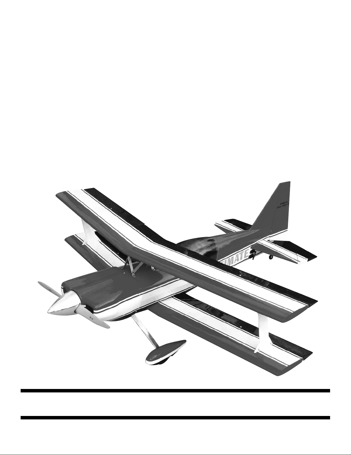
30% Ultimate ARF 3-D ARF
30% Ultimate ARF 3-D ARF
Congratulations on your purchase of the Goldberg Ultimate ARF 3-D ARF.
This is a very unique aircraft, with great 3-D capabilities. Every effort has
been made to produce a lightweight, straight, easy to assemble aircraft.
Because of its oversize control surfaces which are double beveled to allow
for extreme throws, great care must be taken in the set-up and flying of this
airplane. Quality hardware components have been provided to allow for 3D
set-up while maintaining adequate mechanical advantage to eliminate flutter.
It is your responsibility as an advanced pilot to fly the aircraft in an intelligent manner. THR
OTTLE MANAGEMENT IS A MUST!!!!!!!! We at Carl goldberg
have put the 30% Ultimate ARF through a very rigorous flight-testing schedule and have stressed the airframe beyond all practical parameters without
a single failure. Carl goldberg will NOT warrant the Ultimate ARF against
flutter due to improper set-up or excessive speed maneuvers. having said that,
we believe you will find the Ultimate ARF to be one of the most responsive, inthe-grove aircraft on the market. The Ultimate ARF excels at high-alpha
maneuvers including Harriers (both upright and inverted), high-alpha rolls,
and high-alpha knife edge. Torque rolls, waterfalls, knife edge loops and elevators are all within the performance parameters of this unique aircraft.
Just remember to use common sense when flying this high performance
machine.
Page 4
4
30% Ultimate ARF
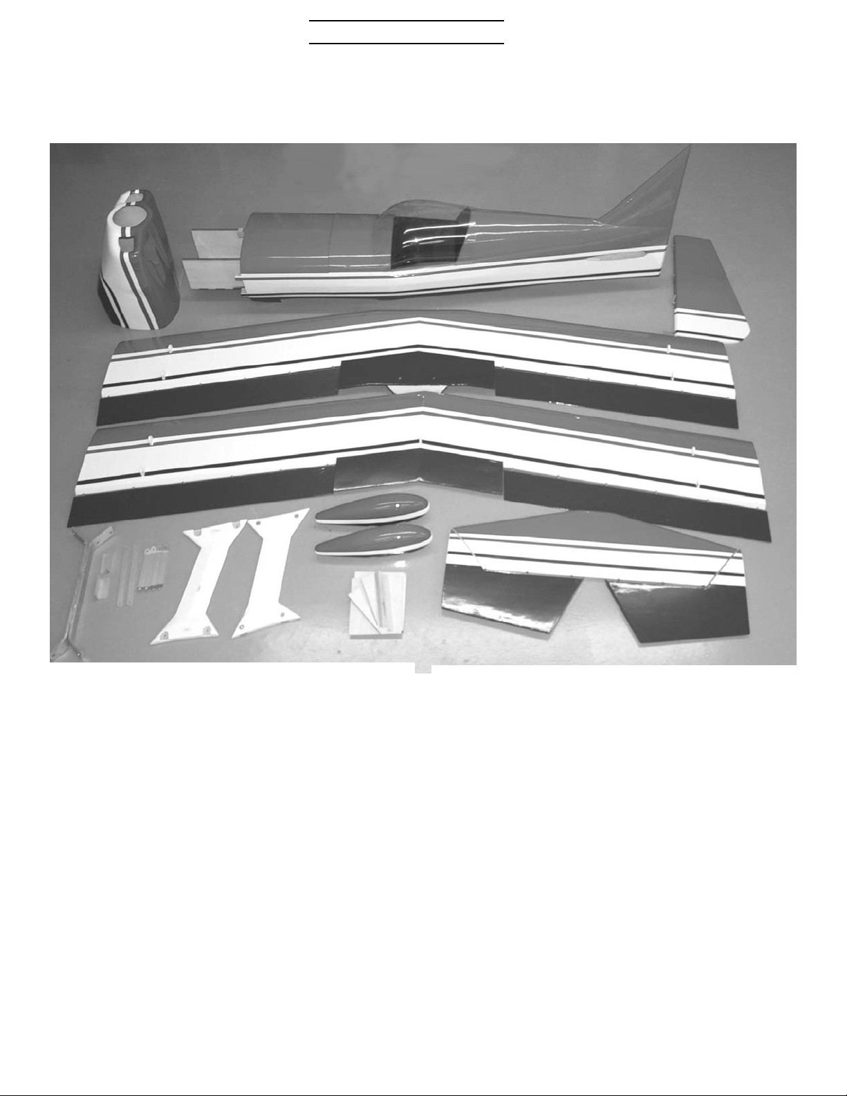
Parts Layout
1.Fuselage
2.Removable cockpit
3.Cowl
4.Top wing
5.Bottom wing
6.Rudder
7.Stabilizer
8.Elevator (2)
9.I-Struts (2)
10.Clear Canopy
11.Wheel pants (2)
12.Landing gear (2)
13.Aluminum angles (2)
14.Cabane struts (6) pcs.
15.Firewall
16.Hardware bag (not
shown)
1
2
10
5
4
6
7
8
8
9
9
3
11
12
13
14
15
Page 5

5
30% Ultimate ARF
Hardware List Quantity per kit Use
6-32x3/4" Socket head screws 20 2 canopy hold down
8 I-Struts
4 cabane struts at fuselage
2 top wing mount at cabane
4 Landing gear aluminum
angles
6-32x1/2" Socket head screws 6 4 cabane strut braces
2 Wheel pant mounts
6-32 lock nuts 6 4 cabane struts
2 top wing mount
6-32 blind nuts 2 wheel pant mount
6-32x 3/4" sheet metal screws 2 tail wheel mount
6-32x 1/2” sheet metal screws 5 cowl mount
1/4-20x1-1/2" socket head screw 4 Landing gear mounts
1/4-20x1" Socket head screws 2 lower wing mount
1/4-20 lock nuts 4 landing gear mount
1/4" flat washers 4 landing gear mount
Tail wheel assembly 1
tail wheel 1
tail wheel tiller spring 1
1/8” wheel collars 2
set screws 2
3/16" axles 2
axle nuts 2
3/16" wheel collars 4
set screws 4
4" wheels 2
6-32x2" Flat head screws 6 4 aileron horns
2 elevator horns
6-32x3" threaded rod 1 rudder horn
6-32 nuts 12 4 aileron horns
2 elevator horns
4 Landing gear aluminum
angles
2 rudder horn
Page 6

6
30% Ultimate ARF
#6 flat washers 17 8 Control horns
4 Landing gear aluminum
angles
5 cowl mount
4-40 golden clevis 16 8 aileron
4 elevator
4 rudder
4-40 jam nuts 16
clevis retainers 16
EZ connector body 1 throttle
screw 1
snap nut 1
2-56x12" throttle push rod 1
nylon snap link 1 throttle
4-40x2-1/8" pushrod 4 ailerons
4-40x5" pushrods 2 elevators
4-40x7-1/2" pushrods 2 rudder
24 oz tank-gasoline 1
14" tie wraps 2 fuel tank mount
laser cut tank mount 1
3/8" sq x1” spruce block 2 Throttle servo mount
Laser cut throttle servo mount 1
Goldberg horn bkts 10 4 aileron horns
2 elevator horns
2 rudder horns
2 tail wheel steering
#4 x1/2” sheet metal screws 10 Motor box cover
#4 flat washers 10 Motor box cover
1/8” dowel x 12” 1 Firewall pins
Page 7
7
30% Ultimate ARF
BUILDING
INSTRUCTIONS
Before starting to build this kit, we
urge you to read through these
instructions. They contain some
important building sequences as well
as instructions and warnings concerning the assembly and use of the
model.
We expect that you have some building experience to take on this model.
This means, every minute detail is not
covered. This is not a basic trainer.
The instructions together with the
simplicity of this kit will allow you to
produce a first class Ultimate .
BUILDING SUPPLIES NEEDED
Hobby knife w/ #11 blade
Thin Zap CA
30 Minute Z-poxy
Thread lock
Wire cutters
Pliers
Drill with bits: 1/8", 5/32", 5/64”
9/64”
Phillips and standard screwdriver
Small clamps
Masking tape
Tape measure
Washable marker
Paper towels
Rubbing alcohol
Begin construction by locating the
two 1/4-20 x 1” socket head bolt used
to bolt the bottom wing on. Put the
bottom wing in place and remove the
covering over the mount holes at the
trailing edge. Bolt the wing down.
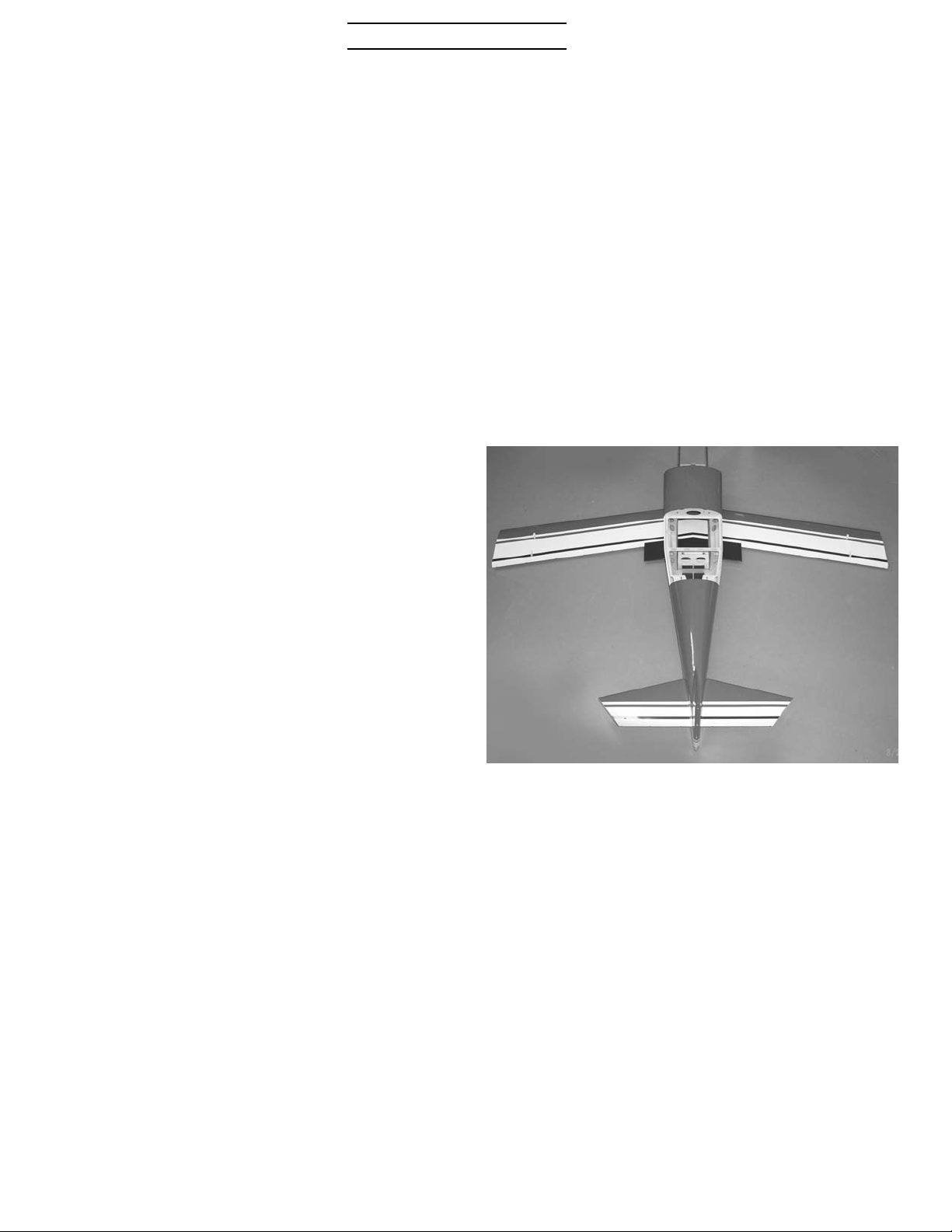
Next locate the stabilizer and fit into
opening in fuselage. Check alignment
with wing, it should be parallel when
sighted from the rear. It should not
be necessary to remove any material
to achieve alignment, simply pushing
up or down on one tip should do it. If
necessary remove material from the
bottom of the stab saddle on one side
to achieve alignment.
Page 8
8
30% Ultimate ARF
Remove the stab and using a sharp
#11 blade, cut the covering about
1/8” inside the line you drew and
remove the covering. Be careful and
do not cut too deep and cut into the
balsa as this will weaken the stab.
Do this top and bottom. Check the
stab saddle in the fuselage and
remove the covering where the stab
will be sitting. Mix some 30 minute epoxy and apply to the bare wood on
the stabilizer where you removed the
covering. Slide the stab back into the
fuselage and align using the marks
you made. Use masking tape pulled to
the top of the fin and bottom of the
fuselage to hold parallel to wing.
Use rubbing alcohol and paper towels to clean up the excess epoxy.
Recheck your alignment and set aside
to dry.
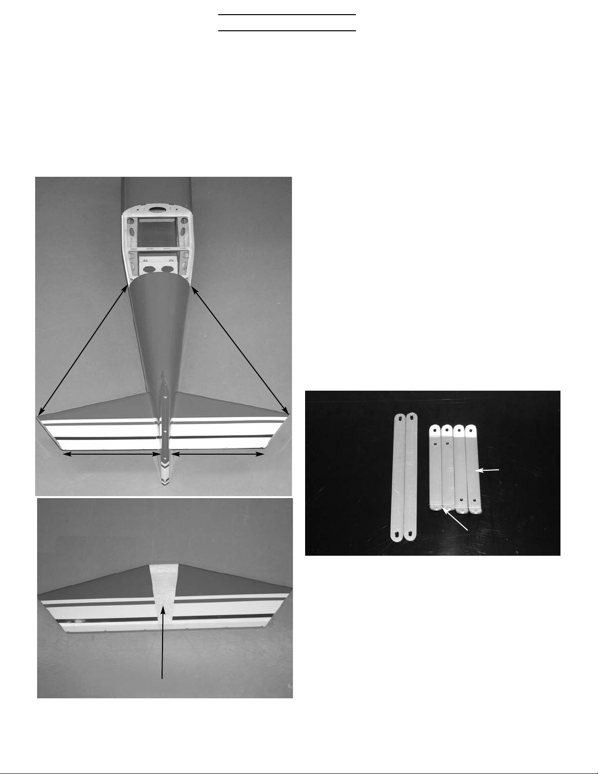
When satisfied with the alignment,
measure to make sure the stab is
square and centered. Measurement A
should be the same on both sides and
measurement B should be the same on
both sides. When stab is aligned, use a
marker and draw a line on top and
bottom of the stab, on both sides next
to the fuselage.
A
A
B
B
remove covering
Top Wing Mounting
Locate the aluminum brackets that
make up the cabane struts. It consist
of six pieces. The two long straight
pieces are the diagonal supports. The
two longer of the pieces with angles
go to the rear and the two shorter
ones go to the front. The sharper of
the two angles are the bottom of the
strut.
rear
brackets
front brackets
Page 9

9
30% Ultimate ARF
Take a straight pin and stick through
the blind nut inside the fuselage to
locate the holes for the struts.
Using the four 6-32x3/4” socket
head cap screws, mount the struts to
the top of the fuselage, short ones in
front longer ones in rear. Do not
tighten the screws down tight at this
time. Leave them loose until the top
wing is mounted.
Locate the two I-Struts and the eight
6-32x3/4” socket head cap screws.
The I-Struts are identified left and
right, top and bottom with small
stickers.
Fit the tabs on the top wing between
the brackets front and rear and
install a 6-32x3/4” socket head cap
screw through the holes. Do not
install nuts now.
Page 10

10
30% Ultimate ARF
Fit the I-Struts in place paying attention to left and right and top and bottom. The I-Struts have recesses in
them that fit over the tabs in the
wings. Install the four 6-32x3/4”
socket head cap screws in each strut.
With the I-Struts screwed in place,
install the nuts on the screws that
hold the top wing to the cabanes and
tighten. Install the diagonal braces
using the four 6-32x1/2” socket head
cap screws and 6-32 aircraft lock
nuts. After these are tight remove
the screws holding the struts to the
fuselage one at a time and apply
thread locker. Reinstall and tighten.
This sequence of install and tightening the bolts will make sure that the
struts are aligned and not under
stress.
Page 11

11
30% Ultimate ARF
Control Surfaces
Locate the predrilled hole for the
aileron, elevator, and rudder horns.
Open the hole up with a 9/64” drill.
Locate the 6-32 x 2” flat head
screws, #6 washers, and 6-32 nuts.
Install the 6-32 bolt through the elevator and secure with a flat washer
and nut. Put a drop of CA on the nut
to make sure it does come loose.
Install the horn bracket flush with
the end of the bolt.
All surfaces are drilled to accept
the large hinge points. To ensure the
proper alignment of the hinges, first
apply petroleum jelly to the pivot
points and then put 30-minute epoxy
into the holes drilled in the stab and
the elevator. Put a little on both tips
of the hinge point and insert the
hinge into the stab and elevator
while flexing the surface up and
down and sliding it into place. This
causes the hinge points to rotate into
perfect alignment.
The rudder horn is a 3” long 6-32
threaded rod. Install with a flat
washer and nut on each side. Use Ca
on the nuts. Install two horn brackets on each side. One faces forward
for the rudder, the other faces rearward for the tail wheel. Hinge the
rudder to the fin using the same
method as the elevator hinges.
The ailerons use the same 6-32 x 2”
bolt, washers, and nuts as the elevators. Install the horn brackets and
hinge all four ailerons using the
same method as the elevators.
Page 12

12
30% Ultimate ARF
Locate the two landing gear legs
and the two 1”aluminum angles.
Using four 6-32x3/4” socket head
cap screws, four #6 washers, and
four 6-32 nuts, mount the aluminum
angles flush against the landing
gear plate and the motor box sides.
Drill two 9/64” holes on each side
through the motor box sides and centered up on the aluminum bracket. It
may be necessary to remove glue
build up in the corner and file the
sharp edge off the corner of the aluminum bracket to make it fit flush.
Landing Gear
Turn the plane upside down and draw
a line down the center of the motor
box and along the front edge of the
gear plate
gear 1/8” off bulkhead on
corner
hole centered over aluminum
bracket
Page 13

13
30% Ultimate ARF
Flat part of gear leg must be
parallel to center line of airplane.
Align the gear so the outside hole
will go through the center of the
aluminum bracket. Align the inside
edge of the gear parallel to the center line. It will be approximately 1/8”
out side the line, don’t worry about
the spacing. The gear should be
approximately 1/8” off the bulkhead
at the rear. Mark and drill the outside hole. Install the 1/4-20 x 1-1/2”
socket head cap screw and secure on
the inside with a flat washer and aircraft lock nut. Just snug the nut up
at this time. Do not drill the inside
hole yet. Install the other gear in the
same manner.
Check that the flat part of the gear
leg is parallel to the center line of
the plane. You can move the gear by
letting it pivot on the one bolt. When
the gear is aligned, drill the other
bolt hole and install the bolt, washer and nut and tighten. You can now
finish tightening the other bolt.
Install the axles on the gear legs. Be
careful and don’t over tighten the
nuts. It looks like a big bolt but the
center is drilled out to accept the
axle and can be over tightened easily.
Locate the tail wheel spring and cut
into two equal pieces. Bend a loop
into each end.
Page 14

14
30% Ultimate ARF
Locate the tail wheel bracket and
align the bend in the strut at the
rear of the fuselage. Center the
mount on the fuselage and drill two
5/64” holes at the hole location.
Harden the holes by using a couple of
drops of thin CA in each hole. Mount
the tail wheel bracket using the two
#6x3/4” pan head screws.
Install the tail wheel with a wheel
collar on both sides.
Attach the tail wheel steering
springs to the horn brackets on the
rudder horn and the tiller arm on
the tail wheel bracket.
Wheel Pants
wood block
Locate the wheel pants and identify
the left and right. The wood mount
block will be on the inside portion of
the wheel pant. Left wheel pant
shown.
Page 15

15
30% Ultimate ARF
Drill a 1/2” hole at the dimple on the
side with the wood block. If you have
a forstner bit you can drill the 1/2”
hole directly, if using a regular drill
start with a small bit and work you
way up slowly or grind out with a
dremel too to prevent damaging the
fiberglass. Support the wood block
on the inside when drilling to prevent knocking the block loose. If this
happens just epoxy back into place.
Block the fuselage up level on your work bench and fit the wheel pants on
the axles with out the wheels. The 1/2” hole will fit over the nut part of the
axle at the landing gear. Block the wheel pants up so they are level and parallel to each other.
Take a 1/8” drill and mark the location of the hole through the predrilled hole in the landing gear.
Remove the wheel pant and drill a
3/16” hole on the mark. Install the
blind nut by pulling it into place with
the 6-32 x 1/2” socket head screw
with a washer on the outside. When
the nut is seated glue in place with
CA being careful not to get glue in
the threads. Put a 3/16” wheel collar on the axle, put the wheel pant
half way on and slip the four inch
wheel on the axle. Install the outside
wheel collar and adjust both so the
wheel is centered in the wheel pant.
Rotate the wheel pant into place and
secure with the 6-32 x 1/2” screw. Be
sure and use thread lock on the
screw.
Page 16

16
30% Ultimate ARF
Cowl Mounting
Slide the cowl into place and mark
the location of the landing gear on
the bottom. Using a dremel tool, cut
slots in the cowl to fit around the
landing gear. The cowl should overlap the fuselage 1/2”.
Cut 5 strips of heavy paper 3/4” wide
and tape in position on the fuselage
so one end is flush with the cowl
mount blocks. Make a mark over the
center of the cowl mount block.
Slide the cowl into position overlapping the fuselage 1/2”. Use masking
tape to hold in place. Make sure the
stripes are aligned on each side. Let
the strips of paper be on the out side
of the cowl. Use a straight edge and
align the top of the cowl with the top
of the fuselage. Make sure stripes
are straight from fuselage to cowl
on each side. Check the left and right
alignment to make sure it is straight
with the center line of the fuselage.
When satisfied with the alignment,
use the mark on the strip of paper to
locate the mounting holes in the
cowl. Drill a 1/16” hole through the
paper, cowl, and into the mounting
block. Open the hole in the cowl up
to 9/64” and install a #6x1/2” sheet
metal screw with a #6 washer. Do
this in 5 places. Make sure firewall
is not touching the cowl on top.
Page 17

17
30% Ultimate ARF
Engine mounting
Locate the firewall, motor box covers, tri stock, and top firewall supports.
With the cowl mounted, measure
from the F1 former to the front of
the cowl ring. Write this number
down.
Measure the engine length from the
mounting plate to the thrust washer.
Subtract this number from the
length of the measurement of the
cowl from former F1. That number is
where you cut the motor box sides.
You will need to add about 1/8” to
the length of the motor box sides for
clearance between the the spinner
backplate and the cowl ring. On
most engines the cylinder will be
behind the engine mount at the bottom and will hit the firewall if the
firewall is not notched out.
Use a square to draw a line on the
motor box sides. Be sure and keep it
square to the box sides as this will
adjust the up and down thrust. Mark
the left side 3/16” longer than the
right to give the desired right thrust.
Page 18

18
30% Ultimate ARF
Epoxy the firewall in place making
sure to keep it square with the sides.
Add the triangle top supports on
both sides and the tri stock on the
back side. Drill 1/8” holes 1” deep in
five places on each side of the motor
box and pin the firewall using 1/8”
dowels and glue.
dowels four
places each
side
You will probably need to notch the
firewall to clear the cylinder head.
If you plan to use a Pitts style muffler you will have to notch the bottom of the firewall. Just cut the firewall and motor box sides to accept
the muffler and then box the area
back in with 1/8” plywood with tri
stock on the inside.
Attach the motor box top covers
using the 10 #4x1/2” screws and #4
washers.
You can cut a hole in the motor box
side to pass the spark plug lead and
fuel line through to the engine.
Page 19

19
30% Ultimate ARF
Shim the engine out if necessary to
get approximately 1/8” clearance.
Move the engine left or right and up
and down till the spinner back plate
matches the cowl. When satisfied
with the fit, use a long drill to drill
the motor mount holes. Remove the
dry wall screws one at a time and
drill and install the motor mount
bolts.
Measure the firewall and draw a
line down the center. Off set this
line 1/8” to the left side of the
plane. Measure up 4-1/2” from the
bottom of the firewall and draw a
line across the firewall. Center the
engine up on the two lines. The best
way to get the engine perfectly
aligned with the cowl is to attach the
engine to the firewall with #6x3/4”
dry wall screws. You don’t have to
drill a pilot hole, just put one in the
top and one in the bottom. They make
such a small hole that you can move
the engine slightly and put another
one in. Install the cowl making the
cutouts for the cylinder head and
muffler and check the fit of the cowl
to the spinner back plate.
Page 20

20
30% Ultimate ARF
Locate the fuel tank and hardware.
Assemble the tank with three lines.
Take one of the pieces of brass tube
and cut into two equal lengths. Bend
the other tube so it will go to the top
of the tank and fit into the raised
portion of the tank. The other two
tubes will just extend past the cap on
both ends. Connect the pickup tube
and clunk to one tube. After the
tank is installed, the vent line (tube
to top of tank) can be plumbed out
the bottom of the fuselage just in
front of the landing gear. The pickup
line (tube with line and clunk) can be
routed to the carburetor, and the
fill line can be routed to a filler
valve, fuel dot or just routed out the
bottom of the fuselage. The fill line
will have to be plugged to prevent
fuel from running out, the vent line
must be left open.
There is a laser cut tank mount furnished with the plane. It is marked
front.
Tip the plate on edge and it will fit in
the cut out in the motor box sides.
Glue in place. This will place the
tank over the CG of the plane.
Page 21

21
30% Ultimate ARF
Place the tank between the holes
and use the two 14” tie wraps to
secure the tank to the mount.
Servo mounting
Locate the laser cut throttle servo
mount and the two 3/8” x1” bass
wood blocks. Epoxy the blocks to the
plate with the triangles underneath.
Epoxy the servo mount to the motor
box side in the proper position to line
up with your throttle arm. Put the E-Z
connector on the output arm of the
servo and connect the 2-56 push rod.
Locate the 2-56x10” throttle
pushrod and nylon snap link. Drill a
hole in the firewall in line with your
throttle arm and connect pushrod.
Page 22

22
30% Ultimate ARF
Locate the two servo cutouts on
each side of the fuselage just under
the stab. Remove the covering with a
sharp knife.
Install the two servos with the output shaft to the rear. You will need
four 24” servo lead extensions.
Locate the two 4-40 x 5” pushrods,
four 4-40 nuts, four 4-40 golden clevises, and four clevis retainer clips.
install a nut and clevis on each end
and with the servo centered, connect
to servo and elevator horn.
Locate the two 7” 4-40 pushrods and
install nuts and clevises on each end.
Attach to rudder output and rudder
horn. After controls are adjusted
install the clevis retainer clips on
all clevises. Tighten the nuts against
the clevises.
Page 23

23
30% Ultimate ARF
Locate the four aileron servo
cutouts in the bottom side of both
wings. Remove the covering with a
sharp knife. You will need four 14”
servo lead extensions. There is a
string located in each cutout to pull
the wire through to the center section. Locate the two 3/4” holes in the
top side of the bottom wing in the center and the bottom of the top wing in
the center. Remove the covering over
these holes. Attach the string you
your servo lead and pull through
wing. Mount the servo with the hardware supplied with the radio with the
output arm to the rear.
Locate the two 4-40 x 2-1/8”
pushrods, clevises, nuts, and retainers. Attach the pushrod between
servo arm and aileron control horn.
After controls are adjusted tighten
the nuts against the clevis and
install retainers.
Locate the two switches, one radio
one motor, just below the hatch rail
just in front of the turtledeck bulkhead on one side. You can glue a couple of rails (not supplied) across the
fuselage in this area to mount the
receiver and two batteries on. The
CG will probably require this area to
be used. You will need an 18” servo
lead extension to reach the throttle
servo, a y-connector to plug in the
two rudder servos, two y-connectors
to plug in the ailerons, plus two 12”
extensions. If you have a computer
radio you can plug the elevator servos into different channels, if not
you will need a servo reverser.
There is a hole in the balsa just
inside the right rear cabane strut.
You can remove the covering and
pass the y-connector through. Cable
tie the y-connector to the cabane
struts so the two ends are at the top
where the leads come out of the top
wing.
Page 24

24
30% Ultimate ARF
Trim the clear canopy to fit hatch.
Install pilot(not supplied) if desired.
Canopy should fit flush with the turtledeck bulkhead at the read and the
canopy frame at the bottom. Do not
glue canopy on with frame off plane.
canopy mount bolt
With hatch bolted in place, put wax
paper between the turtle deck and
hatch and between bottom of hatch
and fuselage side to prevent gluing
hatch to fuselage. If you do not have
the hatch bolted in place when gluing the canopy on , it is very easy to
warp the hatch with the canopy and
then it will not fit on the fuselage.
use a pin through the holes inside the
fuselage to locate the canopy mount
hole. Remove covering from hole and
attach the hatch using the two 6-32 x
1” socket head screws. The blind nut
are already installed in the hatch.
Final Set Up
The CG is 7” behind the leading edge
of the top wing measured in the center section of the wing.
The elevator throw should be set at
1” low rate, 2-1/2” high rate,rudder
2” low rate, 5” high rate, and
ailerons 1/2” low rate, 1-1/4” high
rate.
The cabane struts attach to the top
wing with 6-32 aircraft lock nuts. The
I-strut bolts should be attached
using low strength thread lock.
Regular thread lock may be too
strong and cause the blind nut to
pull out when the bolts are removed.
The canopy should also be attached
using the low strength thread lock.
The cabane struts should already
have regular thread lock on the
bolts where they are attached to the
fuselage, if not be sure and thread
lock them. There is a lot of vibration
with a single cylinder gas motor and
care must be taken to make sure all
the bolts stay put. Run the engine and
range check the radio. Run it at full
throttle to check the vibration and
Page 25

25
30% Ultimate ARF
minutes. Shut the engine down and
check all your bolts, clevises, servos
and linkage. Pull the wing off and
check all the attach points, joints
around the motor box, wing hold
down block, firewall, and any other
joints in the fuselage. Check linkage
to make sure there is no “slop” that
can cause flutter.When satisfied at
all is secure go fly and have fun.
Our models have flown on 4.2 CID
engines both Fox and Precision Eagle
using the Slimline Pitts style muffler.
You will need a 5” Ultimate style spinner like the one shown from TruTurn. We have found the 22-12 Bolly
prop to preform very well on these
engines. You should use at least
1200mah batteries on both the radio
and the engine. Servos should be at
least 70 oz-in or better. We used
Futuba 9151 digital servos.
 Loading...