

Page 1
CARL GOLDBERG PRODUCTS LTD.
P.O. Box 818, Oakwood, GA 30566 • 678-450-0085 • Fax: 770-532-2163 • www.carlgoldbergproducts.com
©copyright 2003 Carl Goldberg Products, Ltd.
Page 2

2
WWAARRNNIINNGG!! TTHHIISS IISS NNOOTT AA TTOOYY!!
TTHHIISS IISS NNOOTT AA BBEEGGIINNNNEERRSS AAIIRRPPLLAANNEE
This R/C kit and the model you will build from it is not a toy! It is capable of
serious bodily harm and property damage. It is your responsibility, and yours
alone - to build this kit correctly, properly install all R/C components and
flying gear (engine, tank, radio, pushrods, etc. and to test the model and fly it
only with experienced, competent help, using common sense and in accordance with all safety standards as set forth in the Academy of Model
Aeronautics Safety Code. It is suggested that you join the AMA and become
properly insured before attempting to fly this model. If you are just starting
R/C modeling, consult your local hobby dealer or write to the Academy of
Model Aeronautics to find an experienced instructor in your area.
Write to: Academy of Model Aeronautics, 5151 Memorial Dr. Muncie, IN 47302
LIMITED WARRANTY
Carl Goldberg Products is proud of the care and attention that goes into
the manufacture of parts for its model kits. The company warrants that for
a period of 90 days, it will replace, at the buyers request, any part or material shown to the company's satisfaction to have been defective in workmanship
or material at the time of purchase.
No other warranty of any kind, expressed or implied, is made with respect to
the merchandise sold by the company. The buyer acknowledges and understands that he is purchasing only a component kit from which the buyer will
himself construct a finished flying model airplane. The company is neither
the manufacturer of such a flying model airplane, nor a seller of it. The
buyer hereby assumes the risk and all liability for personal or property damage or injury arising out of the buyers use of the components or the finished
flying model airplane, whenever any such damage or injury shall occur.
Any action brought forth against the company, based on the breach of the
contract of sale to the buyer, or on any alleged warranty there under, must
be brought within one year of the date of such sale, or there after be
barred. This one-year limitation is imposed by agreement of the parties as permitted by the laws of the state of Georgia.
Important Information
Covering coming loose is not COVERED UNDER WARRANTY. Due to temperature changes the plane may develop some wrinkles in the covering that you
will need to remove with an iron. Be sure to seal the edges down first so that
you do not cause the covering to shrink and leave exposed areas of wood.
Please inspect the plane before beginning to assemble to make sure you are
happy with it. After assembly has begun you cannot return the kit. If you find
a problem before beginning to assemble the plane you must contact us, please
do not return it to the dealer.
Page 3

3
Ex-tr
Ex-tr
eme 5
eme 5
40
40
Congratulations on your purchase of the Lanier Ex-treme 540 3-D ARF. This is
a very unique aircraft, with great 3-D capabilities. Every effort has been
made to produce a lightweight, straight, easy to assemble aircraft. Because
of its oversize control surfaces which are double beveled to allow for
extreme throws, great care must be taken in the set-up and flying of this airplane. Quality hardware components have been provided to allow for 3D setup while maintaining adequate mechanical advantage to eliminate flutter. It is
you responsibility as an advanced pilot to fly the aircraft in an intelligent
manner. THROTTLE MANAGEMENT IS A MUST!!!!!!!! We ar Lanier have put the
Ex-treme 540 through a very rigorous flight-testing schedule and have
stressed the airframe beyond all practical parameters without a single failure. Lanier will NOT warrant the Ex-treme 540 against flutter due to improper set-up or excessive speed maneuvers. having said that, we believe you will
find the Ex-treme 540 to be one of the most responsive, in-the-grove aircraft
on the market. The Ex-treme 540 excels at high-alpha maneuvers including
Harriers (both upright and inverted), high-alpha rolls, and high-alpha knife
edge. Torque rolls, waterfalls, knife edge loops and elevators are all within
the performance parameters of this unique aircraft. Just remember to use
common sense when flying this high performance machine.
Page 4
4
Parts Layout
Page 5

5
2.5mmx10mm screws 7 3 tail wheel mount 4 wire holder
2.5mmx8mm screws 8 hatch covers
2mmx20mm screws 8 control horns
3mmx30mm screws 2 landing gear
3mmx20mm screws 4 motor mount
3mm lock nuts 6 2 landing gear 4 motor mount
3mm washer 12 4 landing gear 8 motor mount
axles 2
8mm lock nuts 2 axle mount
8mm washer 2 axle mount
4mm wheel collars 4
60mm main wheels 2
aluminum gear 2
tail wheel bracket 1
2mm wheel collar for tail wheel 1
25mm tail wheel 1
fuel tank with hardware 1
cable ties 4
2mm pushrods with clevis 4
silicone clevis retainers 4
1.5mmx 6" throttle pushrod 1
nylon sleeve for throttle rod 1
nylon control horns 4
control horn plates 4
elevator joiner wire 1
9/16"x19-5/8" nylon servo lead cover 1
brackets for cover 2
e-z connector body 1
e-z connector screw 1
snap nut 1
snap-r-keepers 4
2-56x1" screws 2 elevator control horn
Hardware List
Page 6
6
BUILDING
INSTRUCTIONS
Before starting to build this kit, we
urge you to read through these
instructions. They contain some
important building sequences as well
as instructions and warnings concerning the assembly and use of the
model.
We expect that you have some building experience to take on this model.
However, every minute detail is not
covered. This is not a basic trainer.
The instructions together with the
simplicity of this kit will allow you to
produce a first class EX-TREME 330 3D.
BUILDING SUPPLIES NEEDED
Hobby knife w/ #11 blade
Thin Zap CA
30 Minute Z-poxy
Thread lock
Wire cutters
Pliers
Drill with bits: 1/8", 5/32", 1/16”
5/64”
Phillips and standard screwdriver
Small clamps
Masking tape
Tape measure
Washable marker
Paper towels
Rubbing alcohol
See the list at the end of the instruction book for a list of additional R/C
equipment you will need to complete
the EX-TREME 540 3-D.
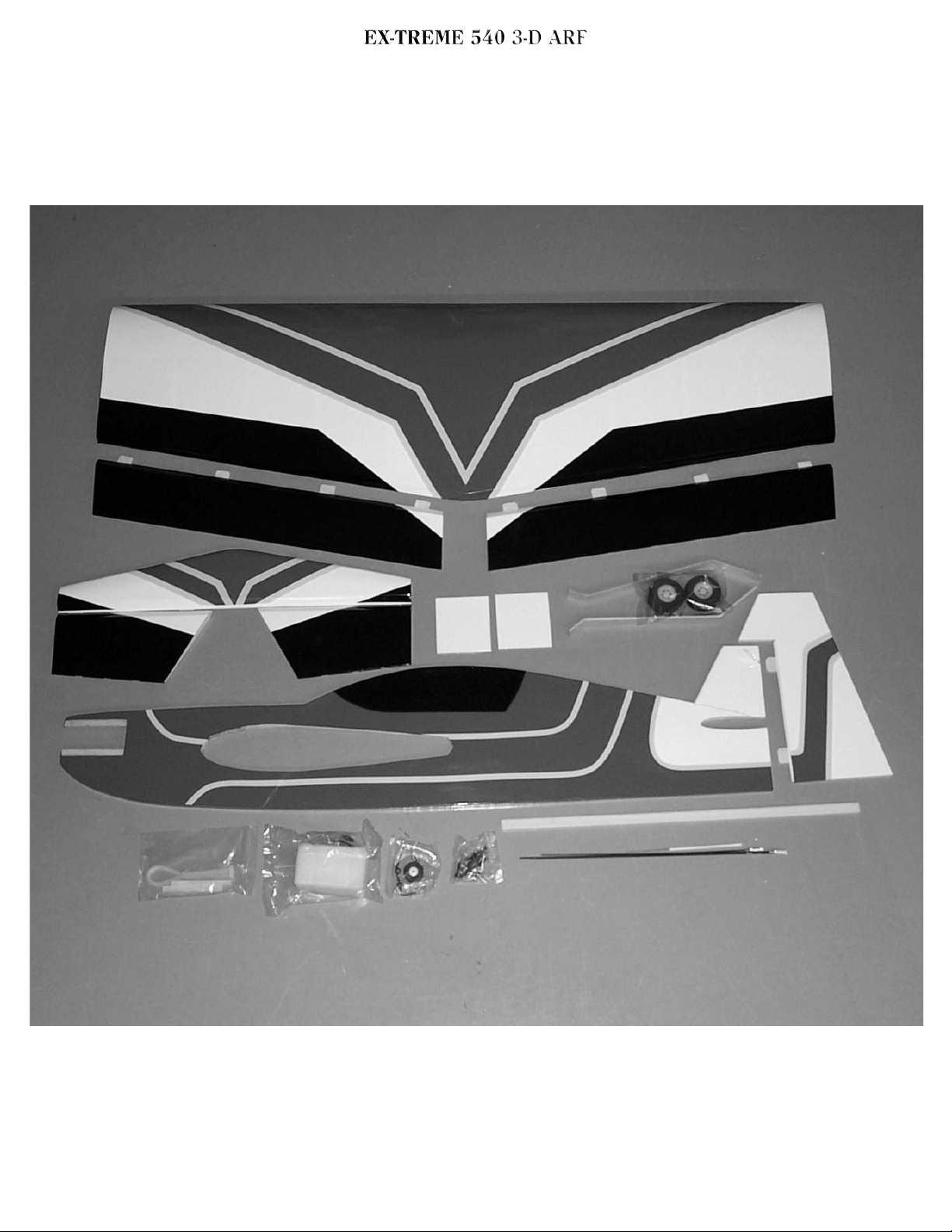
Test fit the wing in the fuse. Make
any adjustments needed with a sanding block or round file. Try to keep
the fit as tight as possible. Use a
ruler to measure to make sure distance A - B and C - D are equal. This is
important to make sure the plane
tracks straight and predictably.
AB
D
C
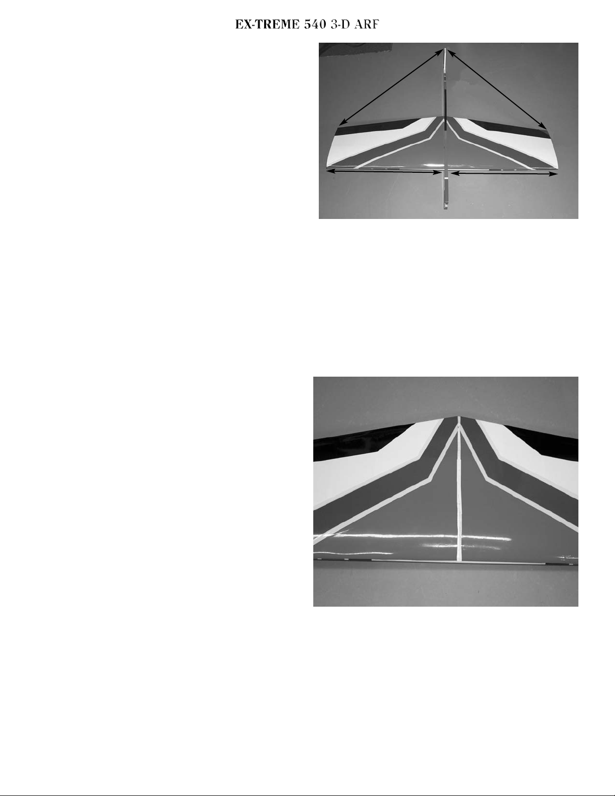
Use a washable marker to mark the
location of the wing in the fuse on
both sides, then remove the wing.
Remove the covering from the wing
joint with a sharp hobby blade, being
careful to only cut the covering and
not the balsa.
Page 7
7
It is easier to do some of the work on
the wing and fuselage before you
glue them together. Locate the template at the rear of the book for
locating the landing gear and cut it
out with scissors. Place it over the
fuselage and drill 1/8” holes at the
location of the mounting holes.
Check the aluminum gear and make
sure it matches the holes in the
paper, if not transfer those holes
and use the template to get the right
angle.
Next mount the aileron servos in the
wing.
Mount with the output arm forward.
The front screws will be a little
hard to get to but can be put in at a
slight angle. Trim the extra legs off
a 4 hole output arm and install on
the servo with the output toward the
inside next to the fuselage.
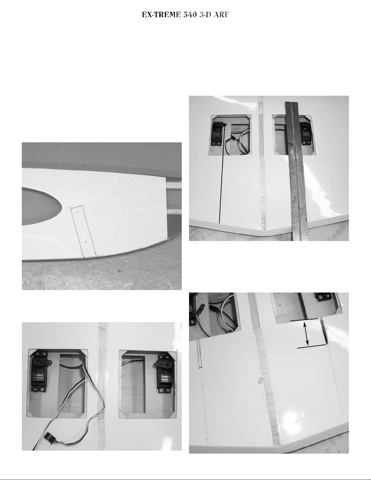
use a straight edge to mark a line
from the center of the servo out put
to the trailing edge, square to the
servo.
1-3/8”
Page 8

8
measure back from the opening 13/8” and cut a slot 1/8” wide centered on the mark you made.
we are now ready to mount the wing
on the fuselage.
Slide the wing back in the fuse,
almost to the wing joint. Coat the
bare balsa at the joint with 30 minute
z poxy and slide the wing in the rest
of the way. Use your marks to realign
the wing, then remeasure A to B, and
C to D. Clean up any zpoxy that
squeezed out with a paper towel and
alcohol. Block the entire assembly
on your workbench until cured.
Test fit the horizontal stab in the
rear of the fuse. Center it the same
way you did the wing using a ruler and
make sure it square to the wing.
Install the tail wheel bracket on the
bottom of the fuselage using 3
2.5mmx10mm screws. Drill a 1/16”
pilot hole in the location of the
three holes in the metal bracket.
Make sure the tiller arm is centered
on the rudder post. before mounting
the bracket, harden the holes in the
fuse by apply a couple of drops of
thin CA in each hole.
center arm
Install the tail wheel and retain with
the 2mm wheel collar.
Mark the covering and remove where
it contacts the fuselage. Reposition
the stab in the fuselage and recheck
alignment. Epoxy in place with 30
minute epoxy.
Page 9

9
Install the gear on the fuselage
using the two 3mmx30mm bolts, four
3mm flat washer, and two 3mm lock
nuts.
Locate the elevator joiner wire and
the two elevator halves. Measure the
width of the stab and lay the elevators spread to that length. Mark the
location of the holes for the elevator joiner wire on the stab.
width of stab
Drill a 1/8” hole at the location of
the mark and notch the leading edge
of the stab so the wire will be flush
with the leading edge. Repeat for the
other elevator half.
Install the axle in the aluminum gear
and secure with a 8mm flat washer
and lock nut. Install one of the
wheel collars, the main wheel and
secure on the outside with the other
wheel collar.
Page 10

10
Glue the joiner wire in place with
epoxy. Make sure the elevators are
lying on a flat surface so both will
be parallel. Use a straight edge to
make sure the leading edge is
straight and the tips are at the proper width.
Fit the elevators in place on the CA
hinges.
Deflect the elevator to full travel
and glue hinges with two drops of
thin CA on each hinge. Turn over and
repeat on bottom side.
Fit the rudder in place on the fin and
mark the location of the elevator
wire.
elevator wire
Go to the bottom of the rudder and
mark the location of the tail wheel
tiller arm.
tail wheel
tiller arm
Page 11

11
At the location of the elevator wire
make a notch approximately 3/16”
deep and 3/8” wide to clear the elevator wire. At the location of the
tiller arm drill a 3/32” hole and slot
the leading edge of the rudder to
accept the tail wheel wire.
notch for elevator
wire
hole for tail
wheel wire
Slide a piece of masking tape between
the tail wheel wire and the fin post.
Put epoxy glue in the hole and slot on
bottom of rudder where the tail
wheel wire goes in. Install the rudder on the CA hinges with the tail
wheel wire in place and pull the
masking tape around to hold the glue
in.
Deflect the rudder fully in one
direction and glue the CA hinges with
two drops of thin CA each. Deflect in
the other direction and glue the
hinges on the other side. When the
epoxy has cured you can remove the
masking tape.
Install the ailerons on the wing and
glue in place by deflecting the
aileron fully in one direction and
apply two drops of thin CA on each
hinge. Turn the wing over and repeat
on the other side.
Page 12

12
Align the aileron control horn Using
the line you drew earlier for the
pushrod slot. Mark the location of
the holes and drill two 5/64” holes.
Install the horn with two 2mmx20mm
screws and the nylon plate on top.
Locate one of the 2mm pushrods
with clevis. install the silicone keeper over the clevis and attach to the
control horn. With the aileron centered and the aileron servo centered, mark the location of the bend
over the output hole in the servo arm.
Bend at 90 degrees and cut off at
3/8”. The servo arm will need to be
drilled with the 5/64” drill. Install
the pushrod through the servo arm
and retain with a nylon snap-r-keeper. Repeat for the other aileron.
Mount the switch for the radio just
behind the radio compartment opening on the left side of the plane.
Page 13

13
The battery will mount on the left
side. Wrap with foam rubber(not
shown for clarity) and insert into
opening.
The receiver will mount on the right
side in the opening next to the servo.
Wrap with foam rubber(not shown).
Route the antenna under the pushrod
and exit from a hole close to the side
of the fuselage. It can then be pulled
down the side of the fuselage and
attached to the top of the rudder.
exit hole for antenna
Using a sharp knife or razor blade,
remove the covering from the servo
cutout just ahead of the stab on both
sides of the fuselage.
Install the rudder and elevator
servo in the cutouts using the hardware supplied with the radio. They
will be on the left side of the plane.
Using the template provided in the
back of the booklet, cut the elevator, rudder servo lead cover to the
shape shown on one end. Transfer
the location of the exit hole on the
template to the cover. Do not cut the
length of the tube, leave full length.
Page 14

14
It will be necessary to cut the back
side out of the nylon cover for the
wires to fit in. Using a sharp knife,
cut 1/16” inside the edge of the
cover. Make sure you are cutting the
back side, it fits on the right side of
the plane. The wires can then be fitted inside by staggering the plugs.
location of
hole in wing
Hold the wire cover against the bottom of the wing on the left side with
the other end centered between the
servos and mark the location of the
exit hole into the wing.
Cut a hole next to fuselage large
enough to get the servo plugs
through but not so wide as the cover
will not hide it.
servo lead hole
into wing.
You will need a 12” servo extension
for both rudder and elevator servos.
Fit the wires into the cover, and
leads into the opening in the wing.
Secure the cover in place with the
two metal brackets and four
2.5mmx10mm screws. Drill a 1/16”
pilot hole and harden with thin CA.
Take two four hole control horns
and install on rudder and elevator
servo. The rudder servo arm points up
the elevator arm points down. Use a
pushrod to align rudder horn parallel to servo arm and mount on rudder
using the two 2mmx20mm screws and
nylon plate.
Page 15

15
Align the elevator horn on the inside
edge of the elevator and mount using
the two #2x1” screws and nylon
plate.
Locate the two 2mm pushrods with
clevis and install the silicone keeper
on clevis. Hook clevis to horn and
mark where it meets the servo arm.
Make a 90 degree bend and cut at
3/8”. You will need to drill out the
servo arm with your 5/64” drill and
install the rod using the nylon snapr-keeper to retain it. Do this to both
rudder and elevator.
Cut the covering from the throttle
servo cutout just behind engine
mount. The opening is made for a Mini
servo. If you use a standard servo you
will need to cut the opening larger.
Trial fit your engine. The right thrust
is built in. Position the engine so you
have about 1/4” clearance from the
front of the prop hub to the front of
the fuselage. Mark the hole locations and drill a 1/8” hole for the
3mmx20mm bolts. Mount engine using
the eight 3mm washer and four aircraft lock nuts.
Locate the fuel tank and position it
on the left side of the fuselage. Mark
the location of the holes for the tie
wraps at the top and bottom of tank
aligned with the groves in the tank.
Pay attention to the lightning holes
in the front of the fuselage under
the covering and make sure you are
not over one of them. Drill a 3/16”
hole at the four locations marked.
Two pieces of balsa are supplied to
space the tank out from the fuselage.
Page 16

16
. If you use a mini servo these will not
be used. If you use a standard servo
you will need them to clear the
servo.
Assemble the tank cap with the big
washer, the rubber stopper, and the
little washer in the rear. For a two
line system we will only use the long
piece of aluminum tube and one short
one.
Insert the tubes through the stopper
and attach the silicone tubing on the
short one. Cut the tubing so that
when the clunk is attached it will be
about 1/4” off the bottom of the tank
when held vertically. Leave the tubes
out the front of the cap about 3/4”
and bend the long tube at a 45 degree
angle so it goes to the top of the tank
when installed.
Install stopper in tank and tighten
the bolt in the center until stopper is
snug. Don’t over tighten. Clunk
should move freely and vent tube
should be to the top of the tank.
Mount the tank using the cable ties
through the holes you drilled. Put a
1/2” piece of foam rubber(not supplied) under the tank to prevent foaming. Do not tighten the tank down
tight, let it move around on the foam
or you will get foaming of the fuel.
Page 17

17
Mount the throttle servo using the
hardware supplied with the radio.
Use the1.5 mm x 6”pushrod and bend
a z bend in one end and attach to the
throttle arm on motor. Attach the ez connector to a three hole servo
arm and attach to servo.
Make a small hole on the bottom of
the wing on the left side to pass the
throttle servo lead into the wing.
You will need an extension to get to
the receiver.
Install the proper prop for the
engine you have chosen and a 2-1/4”
spinner. Set the control throws to
3/8” both directions on low rate and
all you can get on high. On high rate
use 60 percent exponential. Be sure
to use the proper plus or minus
depending on the radio system used.
This airplane is very sensitive on high
rate so be ready for it.
Locate the two hatch access doors.
Drill a 3/32” hole in all four corners of each hatch. Space the holes
off each side 3/32”.
After all wires are plugged into
receiver and battery pack install the
covers by drilling a 1/16” pilot hole
through the hole in the cover and
attach using the four 2.5mm x 8mm
washer head screws.
Page 18

18
The CG should be between 4-3/4” and
5-1/4” for first flight. For 3-D it can
be moved back after you are comfortable with the plane.
Have fun!
AAddddiittiioonnaall EEqquuiippmmeenntt nneeeeddeedd ttoo
ccoommpplleettee yyoouurr EExx-TTrreemmee 554400 33-DD
Minimum of 4 channel radio set
required.
(4) standard servos (1) mini servo
70oz. servos recommended for high
horsepower engines.
(3) 12” servo extensions
Dubro #222 Medium fuel tubing
Dubro #514 1/2” foam rubber
2-1/4 to 2-1/2” spinner
.32 - .46 two stroke engine or .40 to
.63 four stroke R/C engine and muffler.
Prop for your engine choice.
Page 19

19
Exit hole location to
be marked on the
wing
Page 20

20
Page 21

21
Optional Landing Gear
Make your Edge Different from the crowd!
Our New # 257 Profile landing gear will fit your Extreme 540 and look great too. This
landing gear also includes our New #302 5/32” x 1-1/2” Polished Nickel Landing Gear
Axle to give you extra value.
Available
Make your Extreme 330 different from the crowed!
Our new # 257 Profile Nylon Landing Gear will fit you Extreme 300 and look great too. This
Landing gear also includes our new
axles to give you extra value.
# 302 5/32 x 1-1/2” Polished Nickel Landing Gear
1. Mount the nylon gear in the same location
as the aluminum gear.
2. Use (4) 4-40 x 1-1/2” bolts with washers
and locking nuts.
Caution: Make sure that you center the gear
between the lighting holes in the fuselage
sides.
Page 22

22
Ex-treme 540
EX-TREME 330 3-D ARF
The Elevator
This maneuver has your plane drop vertically in a nose
high attitude, depending on wind conditions any where
from a 45 degree angle in low wind to almost backwards
in higher wind conditions. To perform it, at a high altitude
with high rates on, pull your throttle back and feed in the
elevator until you have the full high rate applied. Use the
rudder to guide the plane, and adjust attitude with minor
throttle inputs. You will loose altitude quickly, to recover,
apply full power and fly out level. Watch out for getting
too low or applying too much rudder, it could cause the
plane to snap.
The Harrier
This maneuver has your plane in very slow forward flight
in a nose high 45 degree attitude. To perform it, enter the
same way as you would an elevator, then feed in power
until the plane maintains altitude and starts to fly forward
at a nose high attitude. Maintain it by holding up elevator
and adjusting power, use the rudder to change direction.
Using ailerons may cause the plane to snap and should be
avoided. Add power and push the nose back over to
recover.
Page 23

23
Ex-treme 540
EX-TREME 330 3-D ARF
The Waterfall
This maneuver has your plane flipping around the axis of
the wing, while dropping. Starting from a high altitude, go
to low throttle and gradually pull the nose up to near
vertical. Just when the plane is about the stall, give it full
down elevator and full power. Make attitude corrections
with the rudder and ailerons to keep the plane flipping on
axis. Cut the throttle and hold full down elevator as the
plane flips around to nose high again, add power to flip it
over again. Watch your altitude as to not get too close to
the ground. Neutralize the elevator and add power to
recover.
The Blender
This is a violent maneuver that starts with a vertical rolling
dive that stops the descent as it changes into a flat spin.
Start at a good high altitude, go to low throttle and push
the nose down into a straight dive. Feed in full left aileron
and complete 3 rolls, then immediately move your
transmitter sticks to an inverted snap position, down
elevator, left aileron, right rudder, all full throw. Now
feed in high throttle to flatten the spin and stop the altitude
loss. Recover by neutralizing the rudder and ailerons, and
holding a little down elevator. After you gain some
airspeed you can roll out to upright. Use caution as this is
a violent and high G mauver that will put a great deal of
stress on the airframe.
 Loading...