

Page 1
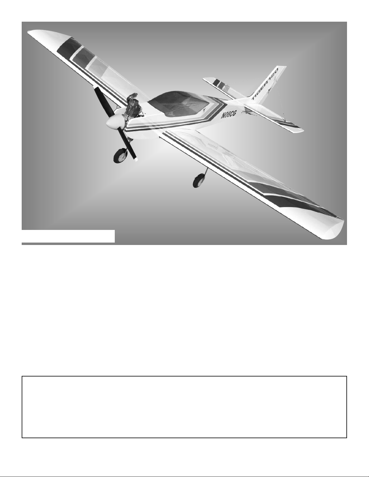
Ideal as a first giant trainer and as a terrific everyday sport plane, the Tiger 120 ARF combines docile flight characteristics with the aptitude for super-smooth, exciting aerobatics. This ARF has been designed to keep building time to a minimum; it's 90% pre-built, with a pre-assembled elevator and installed pushrod and wing guide
tubes, and it features top-quality American hardware and premium covering. So read through these instructions, follow them carefully, and you'll soon be flying a Tiger that "growls as you grow." The better you get the
more fun it gives you!
WARNING
A radio-controlled model is not a toy and is not intended for persons under 16 years old. Keep
this kit out of the reach of younger children, as it contains parts that could be dangerous. A radiocontrolled model is capable of causing serious bodily injury and property damage. It is the buyer's
responsibility to assemble this aircraft correctly and to properly install the motor, radio, and all other
equipment. Test and fly the finished model only in the presence and with the assistance of another
experienced R/C flyer. The model must always be operated and flown using great care and common
sense, as well as in accordance with the Safety Code of the Academy of Model Aeronautics (5151
Memorial Drive, Muncie, IN 47302, 1-800-435-9262). We suggest you join the AMA and become properly insured prior to flying this model. Also, consult with the AMA or your local hobby dealer to find an
experienced instructor in your area. Per the Federal Communications Commission, you are required
to use only those radio frequencies specified "for Model Aircraft."
LIMITED WARRANTY
Carl Goldberg Products has inspected and certified the components of this aircraft. The company urges the buyer to perform his
own inspection, prior to assembly, and to immediately request a replacement of any parts he believes to be defective for their
intended use. The company warrants replacement of any such components, provided the buyer requests such replacement within a period of one year from the date of purchase and provided the defective part is returned, if so requested by the company.
No other warranty, expressed or implied, is made by the company with respect to this kit. The buyer acknowledges and understands that it is his responsibility to carefully assemble the finished flying model airplane and to fly it safely. The buyer hereby
assumes full responsibility for the risk and all liability for personal or property damage or injury arising out of the buyer's use of the
components of this kit.
INSTRUCTIONS
Tiger 120 ARF
© Copyright 2006 Carl Goldberg Products LTD.
P.O. Box 818 Oakwood GA 30566 Phone #678-450-0085 Fax # 770-532-2163 www.carlgoldbergproducts.com
Page 2

2
ITEMS NEEDED TO COMPLETE THIS AIR-
CRAFT
1 RADIO GUIDANCE SYSTEM (5 CHAN-
NEL MINIMUM REQUIRED) 8 SERVOS
2 6” FLAP SERVO EXTENSION WIRES
2 18” AILERON SERVO EXTENSION
WIRES
2 Y-HARNESS
1 ENGINE .90-.1.20 2-CYCLE or .90-1.80 4-
cycle, AND MUFFLER
1 CA Accelerator
1 2 OZ. Bottle medium CA
1 1/2 OZ. Bottle Thin CA
1 30 minute and/or 5 minute epoxy.
1 Foam rubber 1/2”x8”x12”
1 3” Spinner
TOOLS AND SUPPLIES FOR ASSEMBLY.
MODELING OR UTILITY KNIFE
WORK SURFACE (24" X70")
ELECTRIC DRILL
1/16”,5/64” 3/32”,1/8", 5/32”, 1/4” DRILL
BITS
SMALL STANDARD & PHILLIPS SCREW-
DRIVERS
MASKING TAPE
NEEDLE NOSE PLIERS
36” RULER OR TAPE MEASURE
FLEXIBLE STRAIGHT-EDGE
T-SQUARE
30-60-90° x 6" TRIANGLE
SOFT PENCIL
A FEW STRAIGHT OR "T" PINS
ADJUSTABLE WRENCH
WIRE CUTTER
OPTIONAL HEAT GUN/COVERING IRON
ACID BRUSH
NOTE: The Tiger 120 ARF is covered in White
(#870) UltraCote®. The trim colors are
True Red #866, Yellow #872 and Orange
#877.
Page 3

3
USING THIS INSTRUCTION MANUAL
Before you begin assembling your Tiger 120 ARF, take
some time to read through this entire instruction book. It
is designed to take you step-by-step through the process
and to give you added information on engine and radio
selection and set-up, balancing your aircraft, and flying
your model. The time you spend will speed the assembly
process and help you avoid problems.
PREPARING FOR ASSEMBLY
You will need a work area of approximately 24 x 70" which has
been covered to protect it from adhesive, as well as c uts and
other damage. Many people cover their work area with a
sheet of dry wall (sheet rock) and/or waxed paper t o prevent CA and Epoxy from ruining the work surface.
CONSTRUCTION TIPS
IMPORTANT: ALWAYS READ A FEW STEPS AHEAD.
This will alert you to coming instructions and will help you
plan accordingly.
Using the Parts Identification section, familiarize yourself
with the various items included in your kit box.
As you work, CHECK OFF EACH STEP in the box provided, so that you are sure you do not forget anything.
Do not hesitate to ask questions. Your local hobby dealer
and area flyers will most likely be happy to help, as they
want you to have a successful flying experience. You may
also receive technical assistance from Carl Goldberg
Products via e-mail (carlgoldbergproducts.com) or by telephone 678-450-0085.
INTRODUCTION
COVERING
The Tiger 120 ARF is covered in premium iron on film. It
is not uncommon for ARF's to develop a few wrinkles in
transit. If this is true of your model, the situation is easily
corrected. Before you begin putting the pieces together,
run over the surface of each section with an iron (either
specially designed for airplane use or the more cumbersome household iron) or use a modeling heat gun. Apply
the heat (set at about 350° F), following along with a soft
cloth and pressing down on the covering as you go
around. This will more firmly set the covering adhesive
into the wood and keep your aircraft covering tight and
smooth in the future.
One of the great advantages of film is that it can be
applied over itself without causing gas bubbles. This
allows you to repair your aircraft, as well as to customize
it in a number of ways. If, due to a flight mishap, you get
a hole or similar covering damage, simply trim away the
ragged edges and then apply a patch, following the directions that come with replacement film , which is available
at your hobby dealer. In case of a major crash, where
large amounts of the film must be replaced, heat the
damaged covering and then slowly peel up. If you are
applying sufficient heat, the film will come up easily and
leave no color on the wood.
ADHESIVES & GLUING TECHNIQUES
CA adhesives are specially formulated to firmly glue the
plywood, hardwood, and balsa used in your model and to
withstand the vibration and stresses of high performance
flight. However, there are times, such as when you are
installing the stabilizer and fin on the fuselage and want
more set-up time for careful alignment and positioning,
then you should use epoxy. Occasionally, you also will
want to use thin CA, which "wicks" into the surrounding
areas. Aliphatic resin glue or similar water-based glues
can also be used, but they will add to the assembly time
because they dry so much more slowly than CA glue.
Remember, when ever using any CA, you must be careful to read instructions thoroughly, as you will have only
seconds for positioning of parts. Be sure to trial fit parts
together before gluing. Also, never use watery THIN
type CA glue for gluing plywood and hardwood parts.
Thin CA's do not adequately bond these areas.
CAUTION
Some people may experience an allergic reaction when
exposed to fumes from CA glue or epoxy. As with paints,
thinners, and solvents, it is always important to use glues
only where there is adequate ventilation to carry fumes
away. A fan is recommended. Also, special care must
be taken when using CA, as it will bond skin as well as
other surfaces. Before using any CA, carefully read all
label precautions. When using CA, protective eye-wear
and care in keeping the glue away from the face is highly recommended. If CA does happen to get into the eye,
hold lid open and flush with water only. Seek immediate
medical attention.
Page 4
4
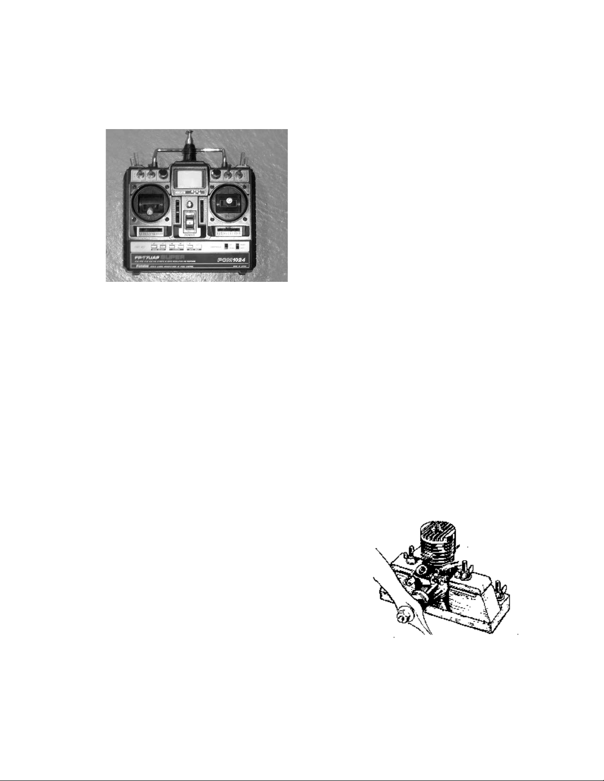
RADIO EQUIPMENT & CARE
There are many fine radio systems on the market. Your
local hobby dealer and club members are good sources
of information on equipment and its suitability for various
projects. It is recommended that you speak to them
before making a final choice.
Today's RC systems are very well engineered and constructed.
However, they
will remain only
as good as the
way in which
they are
USED. Always
follow the rules
of proper
usage and all
manufacturer's
instructions for
your particular
piece of equipment.
TRANSMITTERS: Keep your transmitter clean and free
from fuel residue and dirt. Battery condition and RF output should be monitored, and the system should be
aligned and tuned annually. Do not transport under vibration (such as on the floor of a car) without cushioning.
RECEIVERS: Receivers must be vibration free. When
installing in the aircraft, wrap them in a minimum of ¼" soft
foam rubber (not plastic foam). Keep well clear of all
cables and batteries. Tune annually (or as recommended
by the manufacturer), as indicated below under "CheckUps."
SERVOS: Servos are vibration prone. Be sure to mount
them with grommet shock mounts in servo trays which are
also shock mounted. Also be sure to keep them clean. If
the neutral position "drifts," this is a sign of change which
should not be ignored; find out WHY before flying again.
BATTERIES: Nicads also can suffer from vibration, so
they too should be wrapped in soft foam rubber before
installing. Check their condition periodically by measuring
the voltage with a volt meter or battery tester. Charge the
batteries before EVERY flying session. When not used
for a period of time (such as during the winter months) the
batteries should be charged every 30 days. Never store
batteries in a discharged condition.
PUSHRODS: Obviously, pushrods should be installed to
operate freely, so that they place no load on the servo.
Using a servo's power to move a tight rod or heavy surface by force increases the battery drain, shortens the
electronic life, and can cause neutralizing problems. In
addition, it is important the pushrods do not flex or vibrate.
Any vibration is transferred directly to the servo.
CONNECTORS: In using connectors, never pull on the
wires to disconnect; grasp the plugs instead. Clean them
by dunking in a solvent, such as dope thinner. Tape the
connectors together when installing and make sure there
is no strain on the cables.
CHECK-UPS: A full check-up by the factory or an author-
ized service center should be done AT LEAST ONCE A
YEAR, as well as any time something unusual occurs during usage. A malfunction or "glitch" is the first sign of an
impending failure; it should not be ignored. The checkup
should include tuning and alignment of the system, as
well as battery testing.
ENGINE & PROPELLER SELECTION
When selecting an engine, it is important to stay within
the manufacturer’s recommended range, as failure to
do so is likely to lead to less than satisfactory performance and may well lead to failure of the aircraft.
Remember, that manufacturers design and test their models for specific engine sizes. Therefore, the aircraft is
unlikely to withstand the stresses created above this
range. Many a modeler has watched all his hours of work
and many dollars worth of hardware head earthward
because he did not heed this warning: DO NOT OVER-
POWER YOUR MODEL! Doing so will automatically void
the manufacturer’s warranty.
Typically, size recommendations are for both a 2cycle or a 4-cycle engine. A 2-cycle engine has more raw
power because it has faster RPMs on the propeller. A 4cycle engine swings a bigger prop and therefore creates
more pull. It is also quieter. 4-cycle engines are generally preferred for high performance, more aerobatic planes.
However, if flying a tri-gear plane, a 2-cycle should be
used. The expense of an engine is usually related to
its efficiency. Some engines of similar cubic inch
displacements are more powerful than others. Check
with a dealer or an experienced flyer to learn about the
specific attributes of the engine you are considering.
If selecting a more sophisticated engine, you may go with
the lower recommended range However, if purchasing a
more basic engine, it is probably best to select something
in the higher recommended range. If you are a relatively
new RC pilot, it's probably a good idea to select an engine
that is popular at the flying field, so that if you have any
engine problems, other modelers will be familiar with the
engine and be able to help. REMEMBER: DON'T OVER-
POWER THE AIRCRAFT!
The propeller size must be matched to the engine. For
example, a .60 may use a 11" diameter prop while a .80
can use a 13" prop. Refer to the information that is sup-
plied with your engine for recommended propeller sizes.
It's wise to buy a few spare props, as everyone breaks
them occasionally, and particularly often when learning to
fly.
Balancing your propeller helps to protect your radio from
the damaging effects of vibration. There are good, easy
to use prop balancers on the market. Follow the instructions that are supplied with the prop balancer. Never
Page 5
5
carve or cut a prop near the hub for any reason (such as
to fit a spinner).
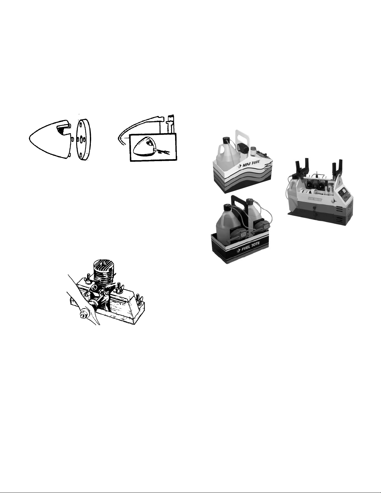
A 3" CGP 4-Pin Snap-On Spinner is available for the Tiger
120 ARF. It is a rugged precision molded spinner that
does not require any special mounting nuts or screws.
Carefully read the spinner instructions and warnings
included in this book. Although a spinner helps reduce
the chance of injury from a rotating prop, extreme caution
always must be used when the engine is running.
As with other precision equipment, a new engine should
be "broken-in" to enhance performance and extend its
life. Breaking-in usually consists of running the engine
with a "rich" fuel mixture and at lower RPMs until all the
moving parts get to "know each other better." This can be
done with the engine mounted in the model or securely
clamped into a CGP Engine Test Stand or similar device.
Refer to your engine's operating manual for the recommended break-in procedure and follow it carefully.
STARTING BATTERY AND GLO-PLUG CLIP: A 1-1/2
volt battery is required to heat your engine's glo-plug for
starting. Wires connect the glo-plug clip to the battery.
Because engine starting draws a lot of electric power
from the battery, rechargeable ni-cad batteries are recommended. Although they cost more initially, they are
more economical in the long run than frequently replacing dry-cell batteries.
FUEL: For best engine performance, use the fuel recommended by your engine's manufacturer. 2 and 4cycle engines require different fuel blends. Ask your
dealer to recommend a good quality fuel.
FUEL PUMP: Needed to transfer fuel from the fuel can
to the model's fuel tank. A simple squeeze-type bulb will
do for small tanks, whereas manual crank or electric
pumps fill larger tanks more quickly.
FUEL LINE: Have about 3 feet of silicone fuel line to
make connections between the fuel pump, the fuel can,
and the model's fuel tank.
EXTRA PROPS: Experts always have a few spares on
hand, so flying doesn't have to stop due to a broken propeller.
CGP ENGINE TEST STAND
FIELD EQUIPMENT
The following equipment will be needed at the flying field
to start your engine, make adjustments, and clean your
model after flying.
FLIGHT BOX: Something sturdy in which to carry your
equipment. CGP's quick-building MiniTote carries the
basics: fuel, starter and battery, and a few essential tools.
The larger CGP Super Tote is economical, easy to build,
and pack lots of utility into little space. They hold fuel,
transmitter, starter & battery, as well as many tools, in a
balanced load that is easy to carry. The fuel tote is
designed to carry your fuel in a handy box that keeps the
jugs from rolling around in your car.
Page 6
6
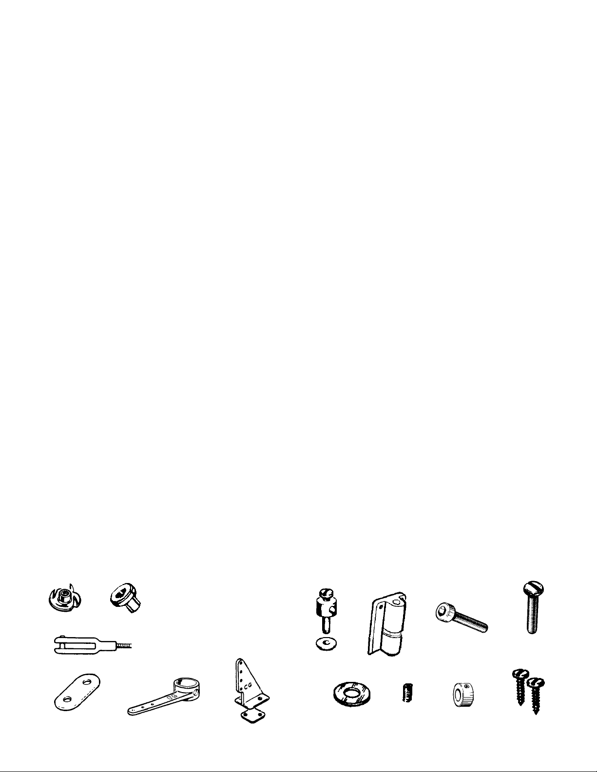
HARDWARE IDENTIFICATION
GLOSSARY OF MODELING TERMS
ARF: Almost Ready to Fly
AILERON: the control surface on the wing that rolls the
plane
AIRFOIL: the shape of the wing as seen from the end
ANGLE OF ATTACK: the angle at which the wing meets
the air flow
BEVEL: to sand to an angle shape
BURR: the rough edges on a piece of wood or metal after
it is cut
CAP STRIP: a thin strip glued to the edges of the ribs to
shape the wing
CONTROL HORN: a device attached to each control sur-
face to provide an attachment point for the pushrod
COWL (COWLING): the nose section of the fuselage that
encloses the engine
DECALAGE: the difference between the incidence of the
wing and stabilizer
DIHEDRAL: the upward angle of the wings, as seen from
the front
ELEVATOR: the moveable part of the horizontal tail,
which controls pitch
EMPENNAGE: the tail of the plan
FIN: the fixed vertical part of the tail
FIREWALL: the hard wooden former at the front of the
fuselage, to which the engine is mounted
FORMER: a piece which shapes the fuselage; and to
which the sides of the fuselage are attached.
GUSSET: a small triangular piece glued into a corner to
strengthen it
INCIDENCE: the angle of the wing or the tail in relation
to the thrustline
LAMINATE: to glue two thin sheets of material together
to form a thick sheet
LEADING EDGE (L.E.): the edge of the wing that first
meets the airflow
LONGERON: a stringer that runs the length of the fuse-
lage
OUTPUT ARM: the piece that attaches to the servo and
connects it to the pushrod
PITCH: an up and down movement of the nose of the
plane, which is controlled by the elevator
PROTOTYPE: the full scale airplane from which the
model design was taken
PUSHROD: the long, stiff dowel, plastic or wire piece that
connects the servo with the control horn
RTF: Ready to Fly
RIB: the airfoil-shaped piece that connects the leading
edge, spars and trailing edge of the wing together
and holds them in shape
RETRACTS: devices for extending and retracting the
wheels on command
ROLL: tilting of the plane as viewed from the front, con-
trolled by the ailerons
RUDDER: the moveable vertical tail of the plane, which
controls yaw
SERVO: the part of the airborne radio system that
moves the control surfaces
SHEAR WEB: wood sheeting that connects the top and
bottom spars to stiffen the wing
SHIM: a thin piece of wood inserted between two other
pieces to improve their fit
SPAR: a wooden stick running lengthwise through the
wing that serves as its backbone
SPINNER: the rounded cone that fits over the propeller
hub
STABILIZER (STAB): the fixed horizontal part of the tail
STALL: a situation in which the plane is flying too slow-
ly to move sufficient air across the wing to produce
lift
STRINGER: a long piece of wood attached to the form-
ers to shape the fuselage
THRUSTLINE: a line drawn from the center of the pro-
peller hub straight through the airplane
TORQUE: a rolling tendency caused by the spinning
propeller
TRAILING EDGE (T.E.): the edge of the wing that faces
the rear of the plane
TRIM: small adjustments made to the control surfaces
to cause the plane to fly straight and level by itself
WASHIN: a twist in the wing that makes the trailing
edge lower than normal
WASHOUT: a twist in the wing that makes the trailing
edge higher than normal
WING SADDLE: the shaped part of the fuselage in
which the wing rests
WHEEL COLLAR: a metal ring that holds the wheel on
the axle
YAW: a right-to-left movement of the nose, controlled by
the rudder
BLIND NUT
EYELET
PUSHROD CONNECTOR WITH SNAP NUT.
NOSE GEAR BLOCK
SNAP LINK
LANDING GEAR
STRAP
STEERING ARM
CONTROL HORN
SOCKET HEAD
SCREW
WHEEL COLLAR
PAN HEAD
SCREW
SHEET METAL
SCREW
SET SCREW
WASHER
Page 7
7
WING ASSEMBLY & INSTALLATION
AILERON and Flap INSTALLATION
1. Collect the following parts:
(1) Left and right wing
(1) Left and right aileron
(1) Left and right flap
(14) CA hinge
2. Locate the pre-cut aileron and flap hinge
slots in both wing halves. Using a hobby knife
(#11 blade), slide the blade into each slot to
make sure it is cleanly cut.
Repeat this process with the ailerons and
flaps, making sure all hinge slots are clean.
3. Place a straight pin into the center of each of
the four CA hinges.
Slide each hinge into the hinge slots on one
of the wing halves. The pin will prevent the
hinges from going in further than halfway into
the wing.
4. Select the aileron for the wing on which you
are working and insert the exposed half of
each hinge into the aileron slots.
Slide the aileron toward the wing until no gap
remains between the aileron and the wing.
Install the flap in the same manner. Align the
stripes on the wing and make sure the
aileron clears the tip and the flap.
5.
When satisfied with the alignment, remove
the straight pins, being sure to keep the
aileron and flap tight to the wing. You may
wish to apply a few pieces of masking tape to
keep the pieces in place.
6. Keeping the aileron, flap, and wing in posi-
tion, apply 3 or 4 drops of thin CA to the small
exposed area of each hinge.
Turn the assembly over and again apply 3 or
4 drops of CA to the exposed hinge surfaces.
Allow to dry for 10 minutes before flexing the
aileron.
7. Repeat the above steps for the other half of
the wing and each flap.
AILERON SERVO INSTALLATION
The following pictures may not exactly match the hardware you are using. Always check the radio manufacturer's instructions when installing radio equipment.
1. Collect the following items:
(2) Wing halves
(4) Servos with rubber grommets
(16)Servo Mounting Screw (supplied with radio)
(2) 18” servo extensions
(2) 6” servo extensions
Page 8
8
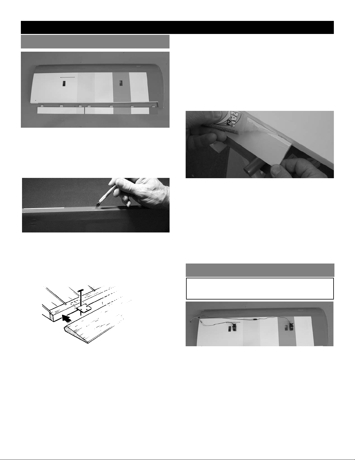
2. Pull the servo leads down through the wing
and exit through the hole on the top surface
of the wing.
AILERON FLAP CONTROL HORN
INSTALLATION
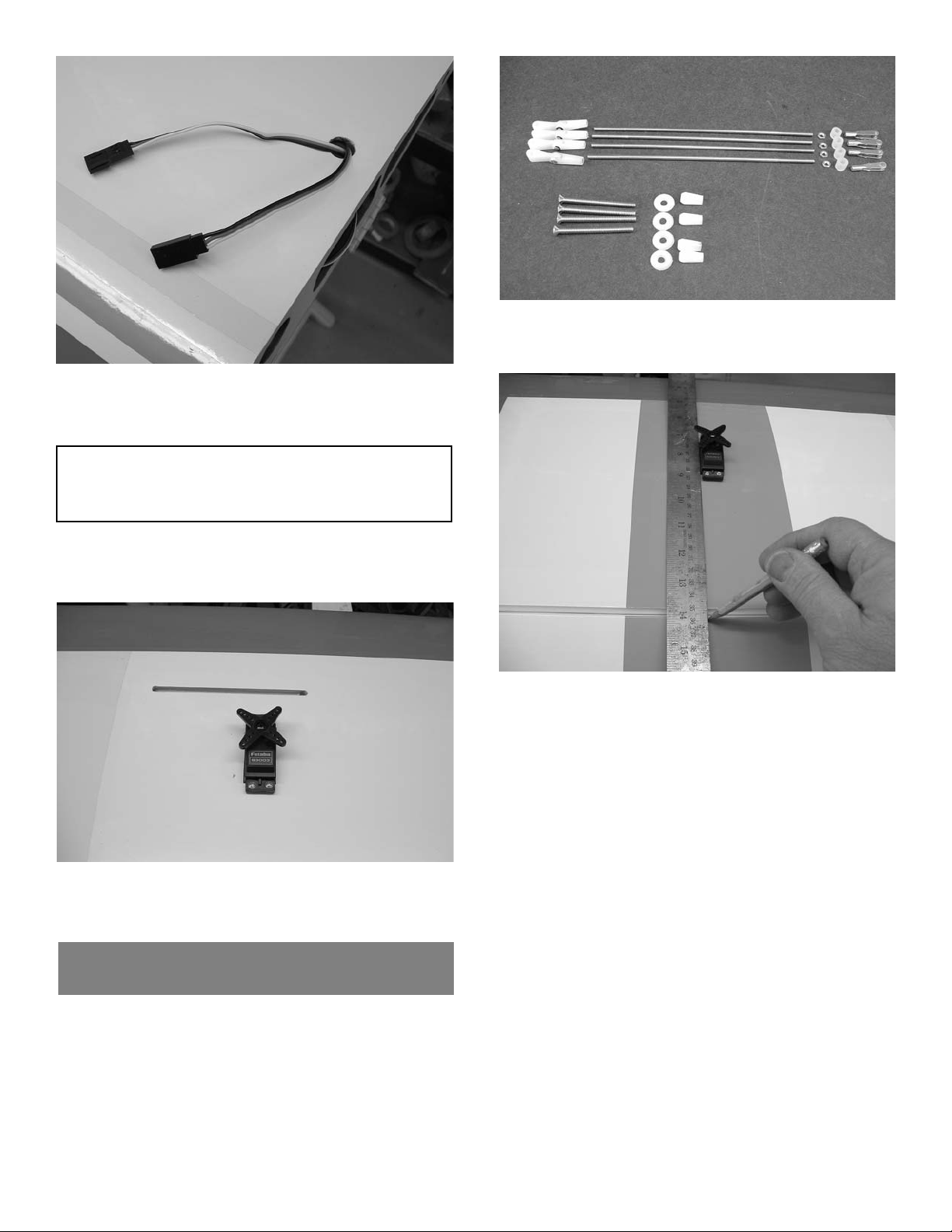
1. Collect the following items
(4) Silicone clevis keepers
(4) 4-40 x 1-3/4” bolts
(4) 4-40 metal clevis
(4) 4-40 nuts
(4) Nylon ball nuts
(4) Nylon washers
(4) Nylon control clevis
(4) 4-40 x 5-1/2” pushrods threaded both ends
2. Use a straight edge and make a mark at a
90º degree angle to the trailing edge and in
line with the side of the servo
IMPORTANT! To ensure that any connections located
inside the wing will not come loose, either when the
wires are pulled, and during flying, always tape them
securely together with electrical tape.
3. Repeat these steps for the other half of the
wing, so that both servo extensions are exiting the holes in the center of the wing.
4. Mount the aileron and flap servos using the
hardware supplied with the radio. The output
arm should go toward the leading edge.
3. For proper operation the aileron servo horn
location should be marked on the outboard
side of each servo (closest to tip). The flaps
will need to be marked on the outboard side
on one wing and the inboard side on the
other wing.
Page 9
9
4. Measure 5/8” back from the trailing edge of
the wing along the mark you made for the
control horn. Drill a 9/64” hole at this location.
Make the hole perpendicular to the trailing
edge of the wing, not square to the surface of
the aileron.
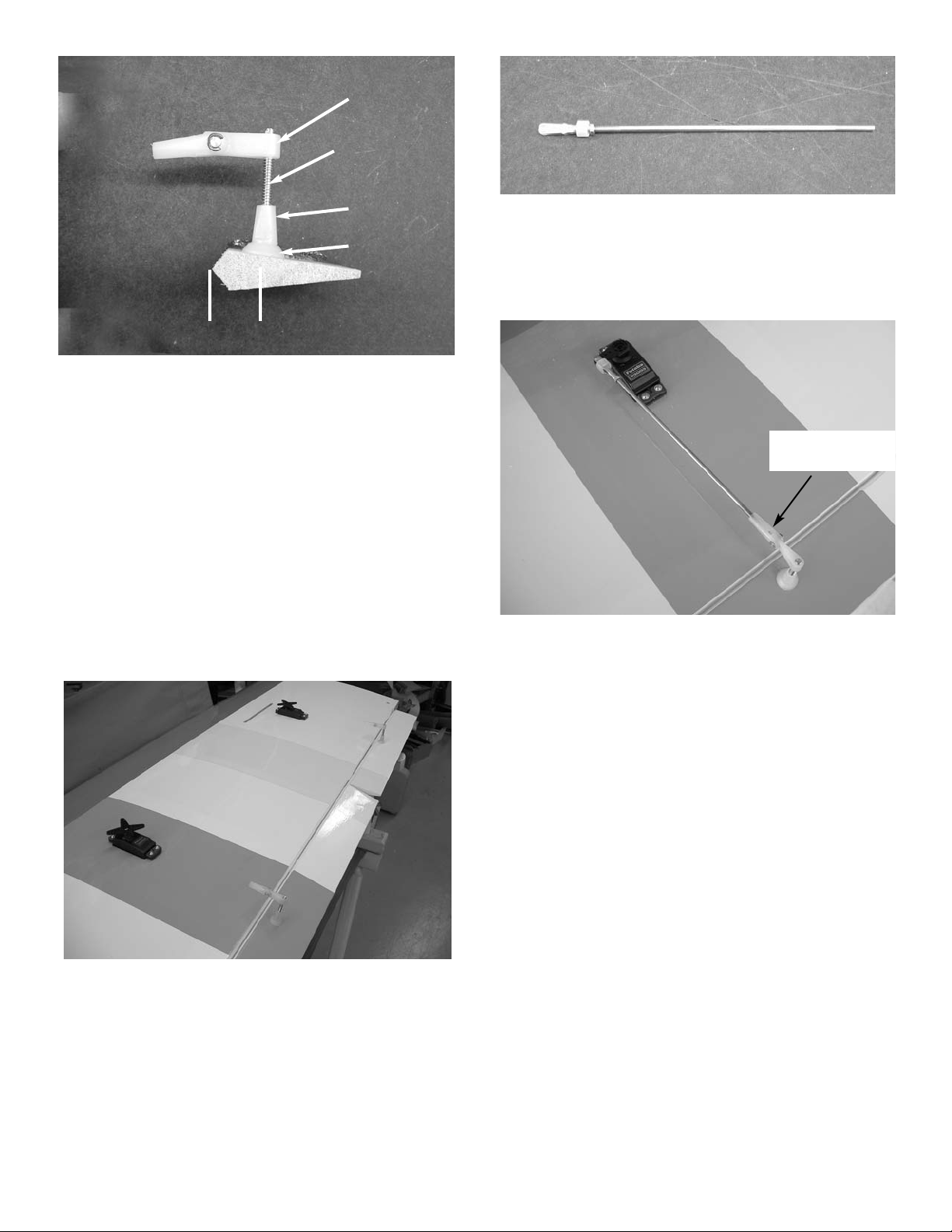
5. Insert the 6-32 bolt through the ailerons from
the top side. No washer goes on the top.
Place the nylon washer on the bottom side
and screw the nylon nut in place. The nut will
self tap onto the screw but it is much easier if
you run a 6-32 tap through the hole first. Run
the tap through the control horn fitting also
and screw into place. Leave it flush with the
top of the screw or one thread down(1/32”) to
provide the mechanical leverage needed.
Control Horn Fitting
Bolt
Nylon Nut
Nylon Washer
6. Repeat for the other aileron and both flaps.
6. Locate the 4-40 pushrods and thread a nut
and a clevis with silicone keeper on one end.
The aileron pushrods are 1\4” longer than
the flap pushrods.
7. Screw the other end of the pushrod into the
nylon pushrod fitting. It should screw in to
the opening in the back of the clevis. Center
the aileron and servo and attach the clevis to
the output arm on your servo. Adjust the clevis to fit.
screw pushrod to
opening in clevis
5/8”
Page 10

10
WING INSTALLATION ON FUSELAGE
3. Insert the large aluminum tube into one wing
half and push the tube into the wing until it
stops. Then insert the small aluminum tube
into the small hole till it stops. Then slide the
wing halves together.
NOTE: If the covering on your wing has loosened
in transit, refer to the covering section of
the "INTRODUCTION" before continuing.
1. Collect the following items:
(1) Right wing
(1) Left wing
(2) 8mm x 36mm aluminum dowel
(1) Large aluminum tube
(1) Small aluminum Tube
(2) 1/4-20 x 2” nylon bolts
(2) Plywood reinforcement plate
2. Using epoxy, mount the 8mm x 36mm alu-
minum dowels into the holes in the leading
edge of the wing. Make sure to leave about
1/2” of dowel sticking out of the front of the
wing. You may wish to slightly taper the
exposed dowel ends for ease of insertion into
the fuse holes.
4. Insert the wing into the wing saddle of the
fuselage by sliding the dowels in the front of
the wing into the holes in the former just forward of the wing saddle.
Align the holes in the wing bolt plate over the
holes in the wing. Insert the 1/4x20 bolts and
tighten.
Page 11

11
TAIL ASSEMBLY & INSTALLATION
1. Collect the following parts:
(1) Stabilizer
(2) Elevators
(1) Wing/fuse assembly
(6) CA hinges
2. As with the wing and ailerons, use a model-
ing knife to make sure the hinge slots are
cleanly cut.
STAB & ELEVATOR INSTALLATION
3. Place two strips of masking tape along the
edge of the stab, next to the outer stab tips
and above the hinge line.
Using a T-square, draw a line from the front
center point of the stab to the rear hinge line.
Measure 13.5" out ("B") from the centerline
and make a mark on the masking tape.
4. Place masking tape on the tip of the fuse, just
in front of the stab.
5. Measure and mark the center point on the
tape.
6. Place a piece of masking tape on each wing
tip, just above the aileron hinge line.
Measure 35" out from the fuselage side to
the wing tip and mark the spot on the tape,
on both the left and the right side of the wing
CENTER JOINT
CENTERLINE
CENTER POINT
7. Place the stab on the platform with the cen-
ter of the stab lined up with the center point
on the fuse.
Measuring from the mark on each wing tip to
the mark on the stab tip, make sure the distance "X" on the right side and left side of the
plane are equal.
13.5”
13.5”
Page 12

12
8. Make sure the stab is level (parallel) with the
wing and insert paper strip shims, if necessary.
9. When satisfied with the alignment of the
stab, temporarily tape securely in place.
Turn over the plane and mark the area on the
bottom of the stab where it rests on the fuse.
Remove the stab from the fuse and, working
1/4" inside the drawn lines, carefully remove
the covering from the bottom of the stab. BE
CAREFUL TO AVOID CUTTING THE
WOOD
10. Spread epoxy on both the bottom of the stab
and the stab platform of the fuse.
Replace the stab on the platform and, after
again checking the alignment of the stab to
the wing, allow the epoxy to dry thoroughly.
11. As with the installation of the ailerons, insert
a straight pin in the center of each CA hinge.
Slide the hinges halfway into the elevator
and then slide the entire assembly into the
hinge slots in the stabilizer.
Allow the elevator/stab assembly to dry for at
least 10 minutes before flexing the elevator.
12. Keeping the stab and elevator in position,
remove the pins and apply 3 or 4 drops of
thin CA to each hinge location.
FIN INSTALLATION
1. Collect the following items:
(1) Fin
2. Trial fit the fit into the fuselage slot on the
rear of the fuselage and the notch on top.
3. When satisfied with the fit, draw lines on the
fuse and stab, on both sides of the fin, showing its location.
Page 13

13
TAKING CARE NOT TO CUT INTO THE
WOOD STRUCTURE UNDERNEATH, and
working inside the drawn lines, carefully
remove the covering where the fin mounts on
the fuse and stab.
5. Remount the fin on the fuse and, using a 90º
triangle, make sure the fin is perpendicular to
the stab.
When satisfied with the fit, remove fin and
mix up a couple of spoonfuls of epoxy.
Apply a THIN, even coat of epoxy on the bot-
tom of the fin and along both sides of the fin
mounting posts. Avoid too much glue, which
will squeeze out from underneath the fin.
Mount the fin on the fuse and place the trian-
gle against the fin to make sure it is perpendicular.
Use masking tape to secure the fin and trian-
gle in position until the epoxy is thoroughly
dry. Make sure not to glue the triangle!
4. Also remove the covering on the bottom por-
tion of the fin where it fits into the fuselage.
Page 14

14
1. Collect the following items:
(1) Rudder
(1) fuselage with Elevators
(3) CA hinges
(2) 6-32 Control horn bolts
(4) nylon control horn fittings
(4) nylon washers
(4) nylon nuts
(1) 6-32 x 2-3/4” threaded rod
RUDDER & ELEVATOR CONTROL HORN
INSTALLATION
4. Using the three CA hinges, mount the rud-
der to the fin, just as was done for the elevator and the ailerons.
2. Measuring from the bottom of the fin along
the leading edge 1-1/8” up from the bottom.
Measure carefully because if you get it too
high on the rudder it will interfere with the
elevator control horns. It should be lined up
with the exit holes in the side of the fuselage.Measure back from the leading edge
5/8” on this mark and drill a 9/64” hole.
Install the 3-1/2” threaded rod through the
hole.
3. Install a nylon flat washer on each side and
screw the nylon nuts in place on each side.
Center the threaded rod in the rudder.
Screw the nylon pushrod fittings on each
end of the threaded rod flush with the end.
Page 15

15
5. Insert the elevator pushrods into the tubes
in the fuselage. Make a mark at the location
they cross the elevator. This should be 11/4” out from the inside edge of the elevator.
Make sure not to get them too close to the
fuselage or they will interfere with the rudder horns. Measure back along this line 5/8”
and drill a 9/64” hole for the control horn.
6. Install the 6-32 bolt from the top (no washer
on top). Place the nylon washer on the bottom and screw the nylon nut into place.
Thread the control horn on the end flush
with the end of the bolt. Screw the elevator
pushrods into the control horn fittings.
Flying wire installation
1. Collect the following items:
(1) Braided cable
(4) 2-56 rigging couplers
(4) 2-56 clevis
(4) Silicone clevis keepers
(8) cable swages
(8) metal cable brackets
(3) 2mm x 13mm bolts
(3) 2mm nuts
2. Take 6 of the metal brackets and grip 1/4” of
the end with a pair of pliers and make a 45
degree bend .
3. Using the 2mm screws and nuts, bolt the
brackets in place on the stab and fin.The
screw should go through the bracket,
through the hole in the stab, then on the
other side of the stab install another bracket
and hold in place with the nut. Repeat for
the fin, one bracket on each side.
Page 16

16
Note: If you plan to do the tail dragger
conversion you should skip ahead to the
tail wheel mounting now. Then come
back to step # 5 below.
4. Take the remaining two brackets and grip in
the center with the pliers and make a 30
degree bend. Measure 1-1/2” from the rear
of the fuselage and screw the two brackets
in place using the #4 sheet metal screws.
You will need to enlarge the hole on one end
for the #4 screw.
5. Take the braided cable and cut two 14-1/2”
pieces and two 11” pieces for the flying
wires. The remainder is the rudder cables.
Slip the cable through the swage then
through the hole in the rigging coupler. Let
1” extend through the hole then bend back
through the swage. Crimp the swage to lock
the cable in place.
Repeat this for one end of each of the four
cables.
6. Put the silicone keeper on the clevis and
screw the clevis onto the rigging coupler.
Screw in into the clevis until the coupler is
flush with the opening in the center of the
clevis.
Repeat for the other three cables.
7. Attach the clevis of the two 14-1/2” cables
onto the brackets on the top side of the stab.
Attach the clevis of the two 11” cables onto
the brackets on the bottom side of the stab.
Screw a #4 nut onto the other four rigging
couplers and screw the couplers into the
clevis. Attach the clevis to the other four
brackets.
8. Pull the top cable through the swage, then
through the coupler on the fin. Loop back
through the swage and pull snug, don’t get it
too tight till the others are in place or you
might warp the stab or fin. Crimp the swage.
Page 17

17
Repeat for the other top cable.
9. Take the bottom wires and fit through the
bottom fuselage couplers and crimp in
place. ( Set-up shown is for tail wheel)
10. After all wires are in place adjust the tension
using the clevises. Adjust equally so as not
to warp the surfaces. The don’t need to be
guitar string tight, just snug.
Page 18

18
OUTFITTING THE FUSELAGE
FUEL TANK ASSEMBLY
1. Gather the following items
(1) fuel tank
(1) rubber tank stopper
(1) clunk
(1) 3mm x 25mm screw
(1) cap washer large
(1) cap washer small
(1) 3mm x 40mm brass tube
(1) 3mm x 60mm brass tube
(1) silicone tube 4mm x 80mm
2. Insert the 3mm screw through the center
hole in the large washer, through the center
hole in the rubber washer against the large
side, and screw the small washer on the
back side.
3. Insert the brass tubes through two or three of
the holes. They should be arranged so as the
long one (vent tube) will be on the right side
of the plane and the short one on the left
side.
The tubes should extend out the front of the
cap 5/8”. Bend the long tube up at about a 20
degree angle. This should be adjusted so the
end of the tube almost touches the top of the
tank when installed.
4, Install the 4mm silicone tube to the short
brass tube and install the clunk to the other
end of the silicone tube. This is the fuel pickup and must be free to “flop” around in the
tank so it can pick up fuel in any attitude.
Decide if you want to use a two line or a
three line tank. Most two strokes use a two
line, one to the carb and a vent tube to the
pressure fitting on the muffler. You can get to
the carb line to remove and fill through.
On most four strokes you cannot get to the
carb easily so plumb a third line into the tank
to use as a fill line. You will fill through it then
plug it for flight. The carb line will stay connected all the time.
5. Install the assembly into the tank so the vent
tube is turned up to the top of the tank and is
positioned on the right side of the tank.
Tighten the screw to expand the rubber cap.
Don’t over tighten or you could split the tank.
Page 19

19
6. Attach the two pieces of 5mm tubing to the
two tank outlets. Use different colors so you
can tell which is the vent and which is the
fuel pickup after the tank is installed. Make a
note of which color you attach to which tube.
The short brass with the clunk is the fuel
pickup and must go to the carburetor. The
long brass tube is the vent and should go to
the pressure outlet on the muffler.
Set tank aside till ready to install.
3. Screw the nose gear blocks to the firewall
with the 4-40 x 5/8" screws and the #4
washers. Don’t tighten the bolts until both
blocks are in place and the nose gear is
inserted in the holes. This will hold the
blocks in alignment while you tighten down
the bolts. Be sure to use locktite on the
bolts.
1. Gather the following items:
(4) 4-40 x 5/8" socket head screw
(4) #4 washer
(1) Nylon nose gear block
(1) Nose Gear Wire
(2) 5mm wheel collar
(1) Nylon steering arm
(1) set screw for steering arm
NOSE GEAR INSTALLATION
2. Cut the two tabs holding the nose gear
blocks together. The blocks have a shoulder
on one side. The shoulder should go toward
the top on both pieces.
shoulder
Page 20

20
ENGINE INSTALLATION
1. In addition to the engine collect the follow-
ing items:
(2) Motor mount
(4) 8-32 blind nut(Installed in fuse)
(4) 8-32 x 1" socket head bolt
(4) #6 x 3/4" sheet metal screw
(4) #8 washer
4. Locate the 1/16” x 18” nose gear steering
pushrod (no threads on either end).Make a
90 degree bend 1/2” long on one end. Put
the end into the outer hole on the nose gear
steering arm and slide the rod into the nylon
tube. Insert the nose gear into the bottom
block then into a wheel collar, then into the
steering arm and finally into the top block.
Push the nose gear flush with the top of the
top block. Tighten the set screw on the
wheel collar and the steering arm.
5. Install the nose wheel and secure with the
other wheel collar.
2. Install the mounts in the fuselage using the 8-
32 bolts and washers. Be sure to use locktite
on the bolts.
3. Position the engine in the mounts making
sure to leave clearance for the spinner back
plate on front.
Page 21

21
FUEL TANK INSTALLATION
1. Collect the following items:
(1) 1/2 x 8 x 12" piece of foam rubber( not
included).
(1) Assembled fuel tank
2. Put one of the 1-1/2" wide foam pieces in the
bottom of the fuel tank compartment in the
fuselage.
3.
Taking note of which tube is the vent and
which is the fuel pickup,route the fuel tubing
into the engine compartment, resting on the
half-circle cut-out in the former.
4. Mark the location of the mounting holes and
drill a 1/8” hole at each location. Mount the
engine using the 6-32 sheet metal screws.
Be careful and don’t over tighten the screws,
they will break easily.
4. Place the fuel tank in the fuselage and
through the opening in the bulkhead and
into the tank compartment and place the
second 1-1/2" piece of foam on top of the
tank.5
5.
Cut the fuel tubing to reach the engine car-
buretor and muffler and attach these cut
ends to the carb and muffler.
HATCH INSTALLATION
1. Slide the hatch tab into the fuse and over the
fuel tank compartment and secure with the
two 4-40 x 1/2” screws.
Page 22

22
CANOPY INSTALLATION
PROPELLER & SPINNER INSTALLATION
1. Collect the following items:
(1 Tinted Canopy
The propeller size must be matched to the engine.
For example, a .60 may use a 11" diameter prop
while a .80 four stroke can use a13" prop. Follow the
engine manufacturer’s recommendation for correct
propeller sizes or speak to a knowledgeable dealer.
It's wise to buy a few spare props, as everyone
breaks them occasionally, and particularly often
when learning to fly.
Balancing your propeller helps to protect your radio
from the damaging effects of vibration. There are
good, easy to use prop balancers on the market. We
recommend sanding the heavy blade on the curved
face, out near the tip, rather than on the flat face. Try
to maintain the normal airfoil curvature. Avoid
scratches which may cause the prop to break. Never
carve or cut a prop near the hub for any reason
(such as to fit a spinner).
It is equally important to use a correctly sized spinner. The CGP 4-pin spinner (3-1/2”) for the Tiger 120
ARF is a rugged precision-molded spinner which
does not require any special mounting nuts or
screws. CAREFULLY READ THE SPINNER
INSTRUCTIONS AND WARNINGS INCLUDED
WITH THE SPINNER. And remember, although a
spinner helps reduce the chance of injury from a
rotating prop, extreme caution always must be used
when the engine is running.
3. The canopy is pre-cut so all that is required is
to run a bead of canopy glue around the
inside edge. Allow the canopy to over lap the
turtle deck at the rear 3/8”. Use masking tape
to hold in place till the glue dries.
2. (Optional) Install any cockpit detail and pilot
figure you desire.
1. Collect the following items:
(1) Braided cable
(2) 4-40 metal clevis
(2) Silicone clevis keepers
(2) 4-40 jam nuts
(4) 4-40 rigging couplers
(4) Cable swages
(1) EZ servo connector
2. Mount the rudder servo on the raised rails in
the center of the servo tray using the hardware supplied with the radio.
RUDDER SERVO INSTALLATION
Page 23

23
3. Put a silicon keeper on each clevis. Thread
a 4-40 jam nut on each rigging coupler and
screw on the clevis. Don’t screw it all the
way in, leave room to tighten the cables.
Attach the clevis to the servo arm.
4. Cut the braided cable into two equal pieces.
Thread one end through one of the cable
swages, through the rigging coupler and
back through the swage. Take the end and
loop it back through the swage again. Crimp
the swage to lock the cable in place.
Repeat for the other side of the servo arm.
5. Use one of the elevator pushrods to pull the
rudder cable out the hole in the rear. Insert
the pushrod in the cable outlet and push forward into the servo compartment. Tape the
rudder cable to the end and pull out the
rear.The cables will need to cross to make
the nose gear work in the proper direction.
Repeat for the other side.
6. Thread the other two 4-40 rigging couplers
into the rudder control horns on the rear.
Center the servo with the radio and center
the rudder. Thread the cable through the
swage, through the rigging couplers and
back through the swage. Loop back through
the swage again. Repeat for the other side.
Pull both tight and with everything centered,
crimp the two swages.
Adjust the cables so the rudder has no play
in it.
Page 24

24
7. Attach the EZ connector to the inside hole
on the rudder arm.
Insert the nose gear steering pushrod in the
EZ connector and adjust. Tighten the set
screw on top.
Elevator Servo & Pushrod Installation
1. Collect the following items:
(2) 4-40 x 36” pushrods
(2) 4-40 metal clevis
(2) Silicone clevis keepers
(2) 4-40 jam nuts
2. Insert the two 4-40 pushrods into the nylon
tubes in the fuselage. Pull them out the rear
holes and screw into the elevator horn
brackets. They should screw all the way
into the clevis.
3. Mount the two elevator servos using the
hardware supplied with the radio. The output
arm should be forward.
4. Install the silicone clevis keeper on the cle-
vis. Screw a 4-40 nut on the pushrod then
the clevis. Attach the clevis to the servo arm.
Center the servo with the radio and adjust
the clevis till the elevator is neutral. Tighten
the jam nut against the clevis. Don’t forget
the arm retaining screw.
THROTTLE SERVO INSTALLATION
1. Collect the following items:
(1) 2-56 x 18” pushrod
(1) Nylon snap link
(1) EZ servo connector
Page 25

25
2. Screw the nylon snap link on the end of the
2-56 rod.
3. Mount the servo on the side of the fuselage
that matches your motor. The right side
pushrod comes out even with the mount for
two stroke engines and the left side comes
out high on the firewall for four stroke
engines.
4. Attach the ez connector to your servo arm.
5. Slide the pushrod into the nylon tube and
attach the snap link to the throttle arm. Fit
the other end into the ez connector on the
servo. Set the servo to full throttle and open
the throttle barrel fully. Tighten the set screw
to lock pushrod in place.
RECEIVER AND BATTERY INSTALLATION
1. Insert the Y-harness into the the aileron plug
in the receiver and then wrap both the
receiver and the battery in the 1/2" foam.
2. Push the receiver antenna into the nylon
tube at the front of the servo tray.
antenna tube
3. The switch can be mounted on the side of
the fuselage opposite the exhaust port.
4. Place the receiver just behind the fuel tank
and the battery in front of the servos. Plug
in all of the servos, keeping both the aileron
and the charge cord accessible.
If necessary for balance the battery can be
moved forward and put under the fuel tank.
Page 26

MAIN GEAR & WHEEL INSTALLATION
1. Collect the following items:
(2) Landing gear wire
(8) #4 x 5/16"screw
(4) Landing gear strap
(2) 3-1/4" wheels
(2) 5mm wheel collar
2. Locate the landing gear slots in the bottom of
the wing and remove the covering material.
Insert the shorter end of the gear into the
hole in the bottom of the slot, so that it points
toward the center of the wing.
3.
Use two nylon straps and four screws on
each side to secure the wire gear.
NOTE: If you desire the tail dragger configuration,
go the the Landing Gear Installation in the Tail
dragger Option section.
4. Install the wheels on the axles, as shown.
The wheel goes on first, followed by the
wheel collar, and the set screw.
BALANCING THE MODEL
IMPORTANT: NEVER NEGLECT THIS STEP WITH
ANY AIRPLANE. If you try to fly a plane with the
balance point behind the recommended range, you
run the risk of having an unstable aircraft and the
strong likelihood of a crash. TAKE THE TIME TO
PROPERLY BALANCE YOUR MODEL!
To determine the Center of Gravity, measure back
on the fuselage 3-7/8" from the leading edge of
the wing. The C.G. range for this aircraft is 3-3/4
to 4-3/4".
Page 27

Place the fully assembled aircraft on a model balancing stand, as shown above. You can make this simple setup with a couple of ¼" dowels with rounded tops, spaced 5" apart. Alternatively, lift the model under the wing
near the fuse by your finger tips. (You may wish to get help from a friend if using the latter method.) Referring
to the recommended balance range for your model, move the position of the plane on the balance stand until the
model is level or the nose slightly down.
If the is tail heavy, shift the R/C equipment away from the heavy end of
the model and recheck until the model will balance within the acceptable range. If shifting the R/C gear still
doesn't balance the model, add weight to the far end of the nose or tail, respectively, until the model is correctly
balanced. The least weight is needed when added as far back or forward as possible. Fasten the weight permanently in place.
TAIL DRAGGER OPTION
NOTE: The tail-dragger option is not recommended
for novice pilots. It is best to get plenty of
practice with a tri-gear before converting
your Tiger 120 ARF into a tail-dragger.
This option might require additional weight
added to the nose of the plane to achieve the
correct CG Balance. The amount of weight
you have to add depends on the weight of
the motor you are using.
The tail wheel option shown is available direct
from Carl Goldberg Products by calling 678450-0085 Monday thru Friday 9:00 to 2:00
EST. This package includes all the hard
ware
required to turn the Tiger 120 in to a tail dragger version.
LANDING GEAR INSTALLATION
1. To configure your Tiger 120 as a tail-dragger,
you will need to purchase the following
items. These items are not included in this
kit.
(1) Main landing gear
(3) 6-32 x 1/2" socket head screw
(2) axles with nuts
2. The blind nuts are pre-installed in the fuse-
lage. Rub the covering with your finger and
locate the holes and remove the covering.
Page 28

28
3. Bolt the main gear in place using the 4mm x
25mm screws.
3. Mount the axle to the landing gears.
4. Install the blind nut in the wheel pant using the
4-40 bolt to pull it into the hole.
Wheel Collars
Wheel Pant
Wheel
Landing Gear
5. Mount the wheel pant on the landing gear
along with the wheel collars and wheels.
Center the wheel on the axle.
Use the 4-40 x 1/2” bolt to hold the wheel
pant to the gear.
Be sure to use thread lock on the bolts.
TAIL WHEEL INSTALLATION
1. Tail wheel package includes mounting hard-
ware.
2. Mount the bracket on the rear of the fuselage
using the #4 x 1/2” screws. Install only the
rear on first.
Page 29

29
3. Mount the two flying wire brackets under the
front mounting screw of the tail wheel bracket.
4. Install the wheel collar with just the set screw
on the axle bracket and insert through the
mounting bracket.
Install the two nylon pushrod fittings on the
ends of the two threaded rods. Screw the
threaded rods into the sides of the other
wheel collar
Install the assembly on the top of the axle
bracket and tighten the set screw. Make
sure the threaded rods are parallel with the
axle.
5. Place the wheel on the axle and secure with
the wheel collar.
spring fitting
6. If you have not installed the pushrod fitting for
the tiller springs you will need to remove the
rudder cables and screw them in place.
7. Install the springs between the rudder horn
and the tail wheel steering arm. Make sure
rudder is centered and tail wheel is straight
ahead.
Page 30

30
FLYING YOUR Tiger 120 ARF
GETTING READY TO FLY
BEGINNING AEROBATICS
Taking time here really pays off later. Rushing the setup and testing frequently results in a model that never
performs up to its full potential and may even lead to a
crash.
CONTROL SURFACE SETTINGS. For the first few
flights, even if you are an experienced flier, it is best to
set the control surfaces at the GENTLE (LOW) settings. You can then work your way up to the higher settings. The settings for the Tiger 120 ARF are:
LOW HIGH
AILERONS 3/8" 1/2"
ELEVATOR 3/8” 1/2"
RUDDER 1-1/2"
RADIO CHECK. Many an experienced flier has rued
the day he neglected to check EVERYTHING! After
fully charging the batteries, turn on the receiver and
transmitter and actuate all controls many times to make
sure all responses are correct. Standing behind the
model, the right aileron should go up when the stick is
moved to the right. Moving the transmitter stick down
should move the elevator up, and vice versa. Also
check the wheel movement, which should move right
with the right rudder movement. Check that the throttle
opens to permit full power when the stick is moved up.
Practice steering the model on the ground, with the
throttle set at minimum, to keep model moving at a
walking pace. Before and after all tests, make sure all
gear is neatly and firmly in place - engine and servos
fastened down, receiver and battery wrapped in foam
and secured against shifting, propeller tight, and antenna extended.
Prior to the beginning of each day's flying, make a
range check of your equipment in accordance with the
manufacturer's instructions. With transmitter antenna
collapsed to 6-8", you should have at least 100 feet
range on the ground. Check this by turning on both the
receiver and transmitter and with the model heading
away from you, walk away while transmitting signals.
Watch to see that no signals are missed until you are
at least 100 feet away. Remember not to use your
transmitter when someone else is flying or testing
on the same frequency. DO NOT ATTEMPT FLIGHTS
UNLESS ALL THE EQUIPMENT WORKS PERFECTLY.
After everything checks out, check it again! When you
are satisfied with the performance of all equipment
functions, point your TIGER'S nose into the wind and,
gradually increasing to full power, take off for a short (2
to 3-minute) first flight.
Before the second flight, take off the wing
and check all screws, radio equipment,
engine mounting, muffler, etc. to make
sure that nothing has come loose.
Spend the following flights getting familiar with your model and making sure it is
properly trimmed for straight and level
flight. When you feel comfortable with your model, it's
time to try aerobatics.
Almost all maneuvers are a combination of loops
and rolls, so if you can do these two things, you're off
to a good start! We highly recommend the book
Flight Training Course, Volume II, published by
R/C Modeler Magazine. Some of the following is
taken from this manual, with the gracious permission
of the magazine.
Above all, remember that top gun aerobatics are the
result of practice. The crisp, graceful movements
come from the pilot's willingness to do and do it again.
Don't give up; practice really does make perfect!
Which side is up? Learning to recognize which side
is up may sound foolish, but many a plane has bitten
the dust because the pilot lost track of the plane's
position. Other than learning to recognize the plane's
silhouette at different angles and attitudes, the best
insurance is to force yourself to concentrate on each
thing that you do, i.e. making a left turn. If your mind
strays and you forget what you're doing, coming
back to it can cause a few new grey hairs!
THE LOOP. This is a good first stunt. The model
starts flying straight and level into the wind, then
pulls up into a smooth, round loop. The up and down
portion should be straight, without the plane falling
off to the right or left, and the speed should be constant. As the plane finishes the loop, it pulls out
straight and level, at the same heading and altitude
as when it entered the maneuver.
THE HORIZONTAL ROLL. Important! Always
remember that, when the plane is inverted, the
elevator works backwards. Therefore, when the
plane is inverted, you give down elevator. Also, be
sure to fly high enough to give a good margin for
error, as your early attempts will probably end up in
a 30º dive. We also recommend you practice with
the plane in front of you, rather than overhead.
Good luck and happy flying!
WIND
(OPTIONAL, BUT
GIVES A MORE PRECISE LOOP
1. UP ELEVATOR
2. EASE OFF OF SOME
UP ELEVATOR
5. EASE OFF OF UP ELEVA-
TOR, OPEN THROTTLE
3. ADD SOME UP ELEVATOR
4. THROTTLE DOWN TO IDLE
75-150 FT.
2. DOWN ELEVATOR
4. UP ELEVATOR
3. RELEASE AILERON
CONTROL
1. FULL RIGHT OR
LEFT AILERON
WIND
 Loading...