

Page 1
1
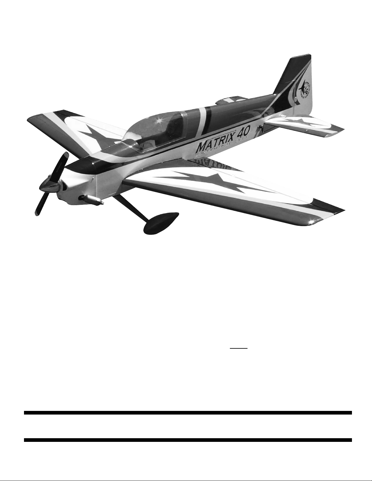
Congratulations on your purchase of the Matrix 40 Extreme 3-D ARF. This is a very unique dualpurpose aircraft, capable of flying any FAI pattern sequence with ease, while exhibiting remarkable
3-D capabilities. Every effort has been made to produce a lightweight, straight, easy to assemble
aircraft. Because of its oversize control surfaces which are double beveled to allow for extreme
throws, great care must be taken in the set-up and flying of this airplane. Quality hardware components have been provided to allow for 3D set-up while maintaining adequate mechanical advantage
to eliminate flutter. It is you responsibility as an advanced pilot to fly the aircraft in an intelligent manner. THROTTLE MANAGEMENT IS A MUST!!!!!!! Carl Goldberg Products has flown the Matrix 40
through a very rigorous flight-testing schedule and have stressed the airframe beyond all practical
parameters without a single failure. Carl Goldberg Products will NOT
warrant the Matrix 40 against
flutter due to improper set-up or excessive speed maneuvers. having said that, we believe you will
find the Matrix 40 to be one of the most responsive, in-the-grove aircraft on the market. The Matrix
40 excels at high-alpha maneuvers including Harriers (both upright and inverted), high-alpha rolls,
and high-alpha knife edge. Torque rolls, waterfalls, knife edge loops and elevators are all within the
performance parameters of this unique aircraft. Just remember to use common sense when flying
this high performance machine.
MA
MA
TRIX 40
TRIX 40
PT. #6135 6/03
CARL GOLDBERG PRODUCTS, LTD.
P.O. Box 88 Oakwood GA 30566 Phone #678-450-0085 Fax # 770-53-63 www.carlgoldbergproducts.com
'Copyright 2003 Carl Goldberg Products, Ltd.
EXTREME 3-D ARF
EXTREME 3-D ARF
Page 2
2
We are very proud of the construction of the Matrix 40 and all of our other ARF aircraft. Each aircraft is jig built to insure a straight true airframe. Every effort is made to build as light an aircraft as
possible. As with any professional builder, glue is used sparingly. Please take a moment during
assembly and run a bead of CA or aliphatic resin into the high stress joints that you can reach
such as the landing gear plate, servo mounting trays, wing hold down blocks, etc. Also, during
the course of shipping from the manufacturer to our facility in the United States, it is not uncommon
for the aircraft to experience several changes in climate. This may cause the iron-on covering to develop wrinkles. This is not a fault of the manufacturer. Please take a few minutes with your heating iron
and heat gun to iron down the seams and re-shrink the covering where needed. The results will be a
beautiful aircraft with a breathtaking finish that you will be proud to display at your flying club.
Important Information
Covering coming loose is not COVERED UNDER WARRANTY. Due to temperature changes the
plane may develop some wrinkles in the covering that you will need to remove with an iron. Be sure
to seal the edges down first so that you do not cause the covering to shrink and leave exposed
areas of wood. Please inspect the plane before beginning to assemble to make sure you are happy
with it. After assembly has begun you cannot return the kit. If you find a problem before beginning to
assemble the plane you must contact us, please do not return it to the dealer.
Page 3

3
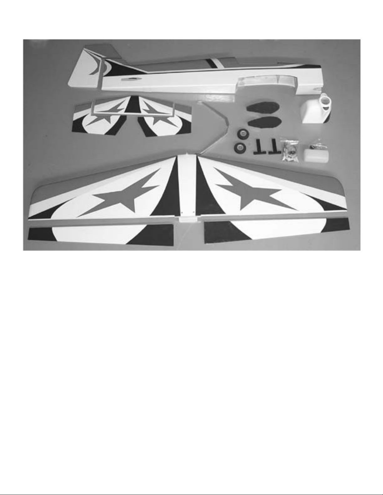
Parts List
1. Fuselage
2. Fiberglass Cowl
3. One piece wing /ailerons
4. Stab/elevator assembly
5. Rudder
6. Fiberglass wheel pants
7. Canopy
8. Fiberglass landing gear cover
Hardware List
1. (2) Motor Mounts
2. (4) 4mm x25mm bolts
3. (4) 4mm blind nuts
4. (4) 4mm lock washers
5. (4) 4mm flat washers
Motor Hardware
Landing Gear
1. Main Gear 1 left 1 right
2. (4) 3mm x12mm bolts
3. (4) 3mm flat washers
4. (4) 3mm blind nuts installed in fuselage
5. (2) 2-1/4” main wheels
6. (2) 4mm x40mm bolts (axles)
7. (2) 4mm nuts
8. (2) 4mm flat washers
9. (2) 4mm wheel collars
Tail wheel
1. (1) Tail wheel bracket
2. (1) 7/8” tail wheel
3. (2) 2mm x10mm screws
4. (2) 2mm wheel collars
Wing
1. (2) 5mm x40mm wing bolts
2. (2) 5mm washers
Elevator pull-pull hardware
1. (2) 2-56 x 29” Threaded Rod
2. (2) Nylon Clevis
3. (1) bellcrank assembly with hardware
4. (2) Nylon swing in keepers
COWL HARDWARE
1. (4) 2mm x10mm screws for cowl mounting
Control System
1. (5) Nylon control horns
2. (5) Nylon control horn plates
3. (8) 2-56 x 3/4” Bolts
5. (7) Nylon clevis
6. (7) Silicone clevis keepers
7. (3) Nylon swing in keepers
8. (2) E-Z connectors
9. (1) 1.25mm x50cm Throttle rod
10. (1) 3.25mm x41.5cm nylon tube
11. (1) 2-56 x 10” Rudder push rod threaded
12. (2) 2-56 x 10” Elevator pushrods threaded
13. (2) 4-40 x 4” Double Threaded Rod Aileron
pushrods.
14. (4) 4-40 Golden Clevis
15. (2) 4-40 Nut
16. (2) Clevis Keeper
Fuel Tank
1. (1) Fuel Tank
2. (1) Rubber stopper
3. (2) Metal caps for stopper
4. (1) Screw
5. (1) Clunk
6. (3) Aluminum fuel tubes
7. (1) Silicone fuel line
Page 4
4
Before beginning assembly of your Matrix 40,
we highly recommend that you study this manual in its entirety. You should begin planning your
radio installation based on your choice of
engine and equipment from the beginning, as
space is limited within the fuselage of the
Matrix 40.
Because the Matrix 40 is intended for those
with some degree of modeling experience,
every minute detail will not be covered. This is
not a basic trainer. Assembly of this aircraft will
be easy for the experienced modeler, and by
following the instructions within this manual and
using the skills you’ve gained during your modeling career you will be able to produce a first
class aircraft.
Building supplies needed
Hobby knife w/#11 blades
Thin CA
Medium CA
Canopy glue
30 minute epoxy
Thread lock
Diagonal wire cutters
Pliers
Assorted drill bits
Various sized screwdrivers( both Phillips and
standard head)
Tape measure
Dry-erase marker
Paper towels
Rubbing alcohol
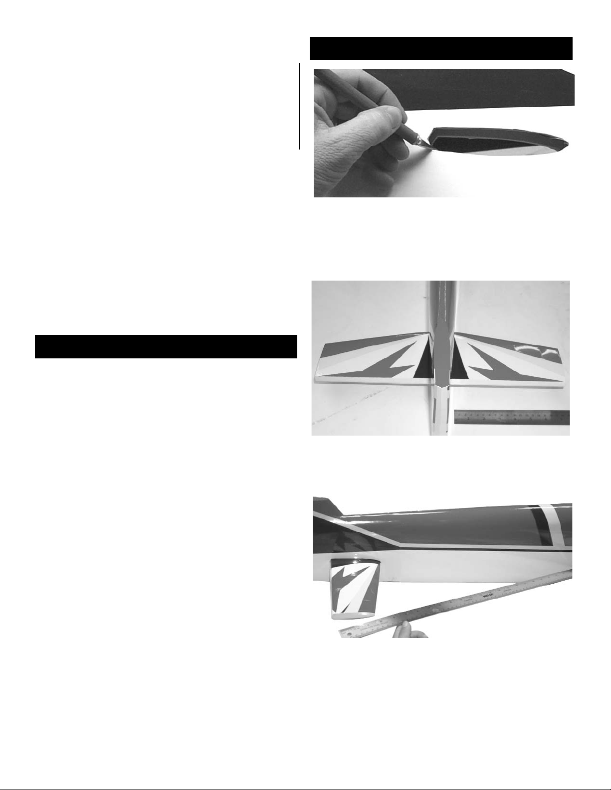
1. Begin construction by locating the fuselage,
wing, wing bolts, washers, and the horizontal
stab. Using a #11 blade, remove the covering
from the stab location at the rear of the fuselage.
2. Insert the stab into the slot and center using
a tape measure or ruler to measure from the
fuselage side to the tip of the stab.
3. With the stab centered, measure from one tip
to the back of the wing cut out. Move stab until
this figure is the same on both sides.
Mounting Stab
Page 5
5
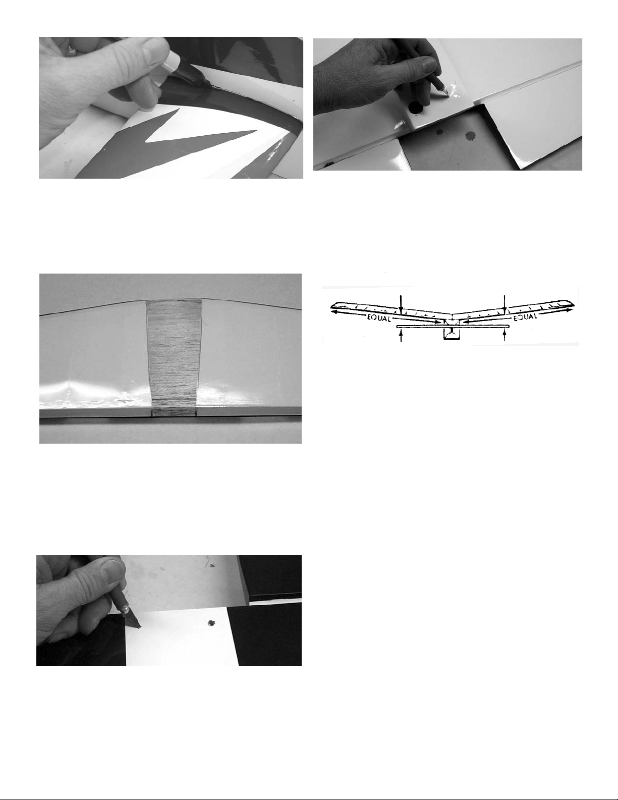
4. When satisfied with the alignment, use a dryerase marker to draw a line on side of the stab,
top and bottom where it meets the fuselage.
Remove stab from opening.
5. Using the #11 blade, remove the covering on
the top and bottom of the stab between the
lines. Cut about 1/8” inside the lines so that
there is no exposed wood when glued in place.
Be careful to cut only the covering and not into
the wood of the stab as this would weaken the
stab.
8. Insert the stab into the fuselage one more
time before gluing and check alignment with
wing. Wing and stab should be parallel. When
satisfied with alignment, remove stab. Mix some
30- minute epoxy and apply to stab opening in
fuselage and to bare balsa on the stab. Reinsert stab into fuselage and check alignment
using all previous methods. Wipe away any
excess epoxy using rubbing alcohol and a paper
towel. Use masking tape to maintain alignment
while glue dries.
6. Using the #11 blade, remove the covering
over the rear wing bolt holes on the top of the
wing.
7. Turn the wing over and remove the covering
over the wing bolt holes. Slide the front wing
dowels in to the holes in the fuselage saddle.
Push down on the rear of the wing till it sits in
the fuselage. Using two wing bolts and washers,
screw the wing down to the fuselage.
Page 6
6
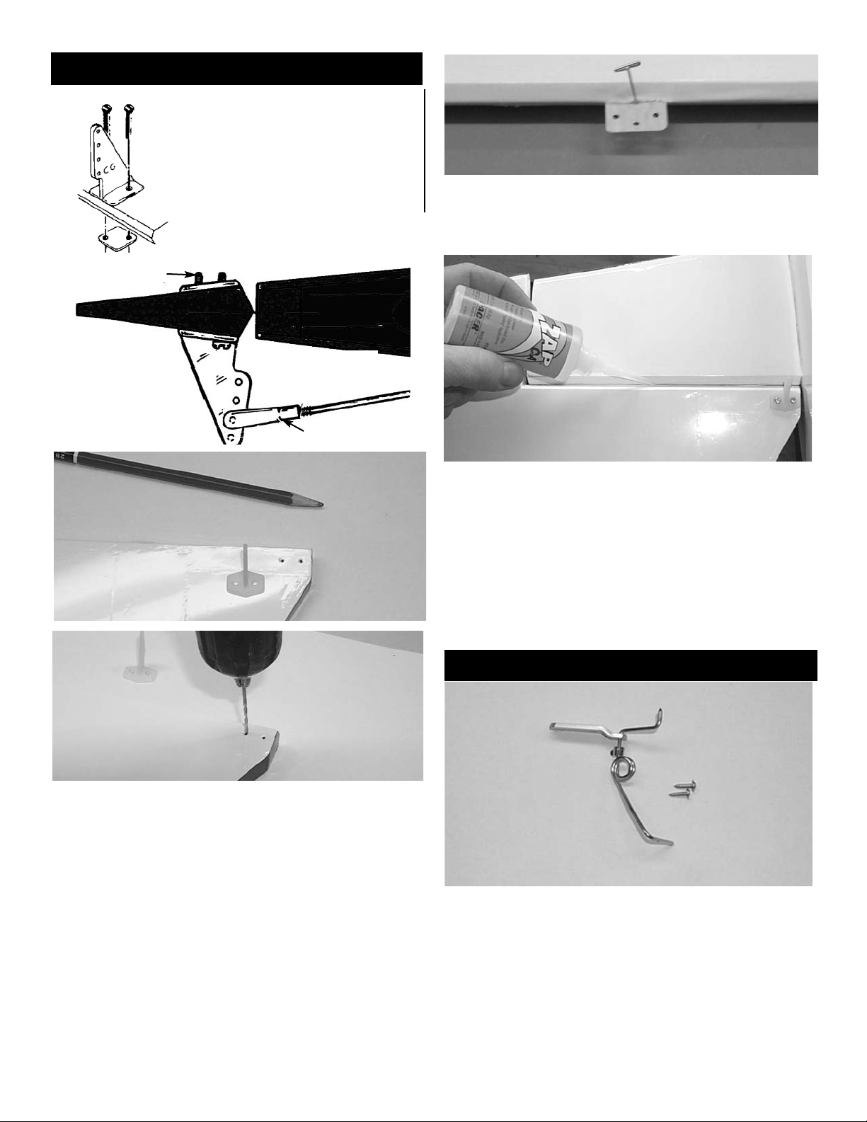
1. While the epoxy dries on the stab, mount the
control horns on the elevators. Align on the
inside edge of elevator on the bottom side, with
the holes on the horn aligned over the hinge line.
Use a square to check alignment of holes over
hinge line, this is important to maintain even
throw on both elevators. Use a long drill, piece of
wire, or pencil to mark the holes through the con-
trol horn. Remove the horn and drill the holes
using a 5/64” drill.
Mount the horns to the elevators using the 2-56
x3/4” bolts and the nylon plates on top of the
elevator.
2. Install the e-z hinges in the stab using a pin
in the center of each to make sure they stay
aligned.
3.Install the elevators on the hinges and with the
elevators pushed tightly against the stab,
remove the pins. Using thin CA, glue each hinge
in place by applying two to three drops on each
hinge. Have the elevators deflected to full up
when gluing the bottom side of the hinges and
deflected to full down when gluing the top side
of the hinges. This will insure that you can get
full throw later.
PLACE CONTROL HORN
AT HINGE LINE
2-56 x 3/4” SCREWS
SNAP LINK
CONTROL
HORN
1. Locate the tail wheel bracket, mounting screws,
wheel and wheel collar.
TTAIL
AIL
WHEEL
WHEEL
BRACKET
BRACKET
Control Horns
Page 7

7
3. Place tailwheel on the bottom of the fuselage
so that the wire is flush with the back of the
fuselage and centered on the bottom.
Drill two 1/16” holes in the location of the
two mounting holes and install the tail wheel
using the 2mm screws.
6. Locate the rudder horn 5” from the bottom
edge of the rudder on the left side. Mark the
holes and drill using 5/64” drill as was done with
the elevator. Mount the horn using the 2-56 x 1”
bolts and nylon plate. Twist the control horn so
that it is facing the rudder servo hole.
5 inches
4. Mark the location of the tail wheel wire on the
rudder and drill a 5/64” hole into the rudder to
accept the tail wheel wire.
5. using pins to center the hinges as was done
with the elevators, install the rudder.
Deflect to full throw and glue the hinges in place
using thin CA.
Page 8

8
Elevator Bellcrank
Elevator Bellcrank
1. Locate the elevator bellcrank hardware.
3. Locate the center tiller arm and the two 2-56 x
29” threaded rod with two nylon clevis.
Install the tiller set screw into the tiller arm.
Thread the nylon clevis onto each of the rods
then snap the clevises to the center tiller arm.
Push the center tiller arm through the fuselage
towards the tail starting at the radio compartment.
2. The aluminum shaft has a hole on one end,
make sure that the hole size is 3/32” by using a
drill in the hole. Install one of the control arms
on the end with the hole using a 2mm screw.
The screw should go all the way through the
arm.
#2 x 1/2” Screw
#2 x 1/2” Screw
#2 x 1/2” Screw
4-40 Set Screw
4-40 Set Screw
You may need
only one spacer
Plastic Collar
Elevator Pull-Pull Wire
Crimp the brass tube
3/32”
Mark and drill a 3/32” hole
through the aluminium
shaft, then mount the control hore with a #2 x 1/2”
screw.
Page 9

9
5. Install the shaft through the mounts by first
putting a washer, then the ball shaped
bearing,and inserting in one side. You must
then install the tiller arm on the shaft as it passes through the fuselage. On the other side install
the ball shaped bearing, another washer and
then the other control arm. You must now mark
the location of the hole on the aluminum shaft
and drill a 3/32” hole to accept the 2mm screw.
Install the screw through the shaft and into.
Rotate the shaft so as both control arms point to
the bottom of the fuse. Through the access hole
on the bottom of the fuse. Center the tiller arm in
the fuselage and tighten the set screw. (See
Drawing on top of page 8)
6. you can mount the hatch cover on the bottom
of the fuselage using clear tape or screws (not
included)
open hole
4. Using your #11 blade, open the hole on both
sides of the fuselage. Install the mounts in both
sides using the 2mm screws supplied. There is
an access hole in the bottom of the fuselage for
installing the plate on the inside.
Note: You may need to make the hole slightly larger. Use a dowel with sand paper to
help open the hole. Do not open the hole
more than required.
7. Center the elevator servo in the tray and
mount the servo using the hardware supplied
with the radio.
Place the elevator pushrods on top of the servo
arm.
8. Making sure that the elevators are level, mark
the outer hole location on the pushrods and
make a 90 degree bend.
9. Insert the pushrods through the bottom of the
servo arm and install the nylon swing in keepers.
Cut off the remainer of the wire so 3/8” is showing.
Page 10

10
11. Locate the two 2-56 x 10” elevator pushrods
and thread a clevis on each. Install the clevis on
the elevator horn and mark the location of the
bend at the bellcrank. Bend the rod 90 degrees
and cut to a length of 3/8”.
12. Install the elevator pushrod using the two
short nylon swing in keepers on the bellcrank
end.(Don’t forget to use the silicone retain-
ers)
Rudder Servo
1. Remove the covering over the rudder servo
cutout with your #11 blade. It is just above the
elevator bell crank hole on the right side of the
plane.
2. Install the rudder servo using the hardware
supplied with the radio. You will need an 18”
extension added to the servo lead.
3. Locate the 2-56 x 10” pushrod and thread a
clevis on the end.(Don’t forget the silicone
keeper) Install a servo arm on the servo and
center the servo. The servo arm should be
positioned pointing up parallel to the rudder
hinge line. Mark the location for the bend and
make a 90 degree bend. Cut off at 3/8” and
install in the servo arm using the swing in nylon
keeper to retain it. The hole in the servo arm
will need to be drilled to a 5/64”.
Page 11

11
Ailerons
1. Hinge the ailerons on to the wing using pins
and Thin CA just like the elevators and rudder.
2. Locate the servo hole in the wing and remove
the covering with a #11 blade.
8-1/4”
4”
3. Install the servo using the hardware supplied
with the radio. Inside the cutout you will find a
piece of nylon fishing line to pull the aileron
lead to the center of the wing. Tape your servo
lead to the fish line and pull it out the hole in
the center of the wing.
Bottom side of wing
4. Install a control horn on the servo and center
the servo with the arm paralle to the hinge line.
Locate the position for the control horn by laying
a 90 degree triangle down. Keeping the bottom
of the triangle parallel to the hinge line and the
top even with the outer servo arm hole.
Aileron
5. Mark the location and drill two 5/64” holes.
Mount the horns using the 2-56 x 3/4” screws
6. Screw a 4-40 nut and metal clevis on each
end of the 4-40 pushrod. Adjust the length of the
pushrod till the aileron is level.
Tighten the nuts against each clevis.
Place the clevis clip onto each of the 4-40 clevises.
Page 12

12
Landing Gear and Wheel Pants
1. Locate the landing gear and bolt in place
using the four 3mm x12mm bolts and flat washers. Use thread lock compound. The blind
nuts are already installed in the fuselage.
2. Locate
2- wheels
2- axles (4mm bolts)
2 4mm nuts
2 4mm washers
2 4mm wheel collars
2 Wheel pants
4 #6 washers
3. Locate the two fiberglass wheel pants. Look
inside the wheel pant and identify the plywood
pad. This pad is on the inside portion of the
wheel pant and goes against the landing gear.
The pants are just alike except for this mounting
pad. drill a 5/32” hole into this mounting pad,
1/4” up (or into the bottom of that pad) from the
bottom edge and centered on the wheel opening.
4. Insert 4mm bolt through landing gear and
hole in wheel pant. Place the washer over the
bolt and start the nut on the end. You will now
have to put the two #6 washers and the wheel
into the wheel pant and let the bolt go into the
wheel as you tighten the nut down. When the
nut is tightened all the way down, it will clamp
the wheel pant to the landing gear leg. You can
rotate the wheel pant into the correct position
and finish tightening the nut. A drop of thread
lock works well here. You can then install the
4mm wheel collar on the end of the bolt to hold
the wheel in place.
Note: The wheels provided are good for asphalt
run ways but not for some grass fields. Use a 23/4” wheel for grass run ways. You might have
too open the bottom of the wheel pants more.
Page 13

13
Engine Mounting
1. Locate
2- motor mounts
4- 4mm x25mm bolts
4- flat washers
4- lock washers
4- blind nuts.
4- #6 x 3/4” Screws
2.Mark the firewall as shown above.
3. Place you engine in the mounts and adjust till
the prop washer is 4-3/4” from the firewall.
Clamp the engine in place and and mark the
location of the mounting holes. Drill using a
7/64” bit.
Screw the engine onto the motor mounts
using the #6 x 3/4” screws.
3-9/6”
1-15/16”
Centerline
4-3/4”
Note: The distance that is shown is for using a
Carl Goldberg spinner. If you are going to use a
different spinner, the front of the cowl needs to
be 4-5/8” from the firewall.
4. Keeping the engine perpendicular to the table
top, clamp the other motor mount to the engine.
Mark and drill the second motor mount then
screw the mount to the engine.
Page 14

14
6. Drill a 9/64” hole in the firewall in position with
the throttle arm. Insert the 3.25mm nylon sleeve
in the hole. Install an e-z connector in the throttle arm and install the 1.25mm x50cm pushrod.
drill your fuel line holes at this time.
5. Align the motor on the firewall. Center the
engine on the off center vertical line and the horizontal line. Drill holes on the marks using a
3/16” drill. Insert the blind nuts into the rear of
the fire wall and tighten using washers and lock
washer (use thread lock).
Glue the nylon sleeve to bulkhead
7. Mount the throttle servo in the servo tray
ahead of rudder servo. Position the servo so
that the servo arm is on the same side as the
throttle pushrod. This may vary depending on
the engine used. Glue the nylon sleeve to the
bulkhead to prevent flexing of the rod. Install
another e-z connector on your servo arm and
attach to the throttle pushrod.
Fuel Tank
1. Locate the fuel tank and hardware.
2. Assemble the cap by inserting the screw
through the large washer, through the black rubber and threading into the small washer on the
back side. Insert the three metal fuel lines into
the holes in the cap. The short line will be the
pickup line and will have the silicone tubing
attached to the back end. On the other end of
the silicone tube install the clunk. This should be
adjusted in length so the clunk is about 1/4” off
the bottom of the tank. One of the long tubes
should be bent so it rest against the top of the
tank. This is the vent line. The other tube will be
the fill line. Insert the stopper in the tank and
mark the fill, vent, and pickup line so you don’t
get them mixed up later. If you are using a YS
engine which pressurizes the tank, you should
wrap the tank in strapping tape with a couple of
loops going around the cap to make sure it does
not blow off.
Page 15

15
3. Install the tank in the fuselage in the notches
provided in the bulkhead, and hold in place with
foam(not provided). Attach the fuel lines(not
provided) to the three metal lines and route
through the hole in the firewall and to your
engine. If you are using an engine without a
pump or pressure system you will probably
have to mount the tank in the nose of the plane.
Cowl installation
1. The easiest way to cut the opening for the
muffler, needle valve, and head is to use a
piece of cardboard and cut it to fit around the
part you are fitting. Tape the cardboard to the
fuselage about 1” behind where the cowl will
end. You can now remove the muffler, slide the
cowl in place and transfer the hole to the cowl
from the paper template. You will need to start
with the head because the cowl will not go on
until the head clearance is cut. A Dremel tool
with a cutter and a sanding drum does the best
job.
2. After all the cutouts are made in the cowl, you
can use the same method to mount the cowl.
Tape the paper templates to the fuse side and
make a hole that will be in line with the firewall.
This needs to be about 1/8” back from the front
edge of the firewall so the screws will hit the
solid wood of the firewall and not just the soft
balsa of the sides. With the templates in place,
install the cowl and put your spinner back plate
in place. Place a 1/8” shim between the cowl
and spinner backplate and tape in place. When
satisfied with the alignment of the cowl, transfer
the holes from the paper templates to the cowl.
Remove the cowl and drill 5/64” holes at this
location. Reinstall the cowl and tape back into
position. Use a 1/16” drill to drill pilot holes for
the screws through the holes in the cowl. Install
with the 2mm screws provided. It is a good idea
to remove the cowl and harden the mounting
holes by dropping a couple of drops of thin CA
into each hole. Let cure before reinstalling.
Page 16

16
Canopy
1. Locate the canopy and trim to the scribe line.
It is a good idea to trim about 1/8” outside the
line at first and then trim to fit so as not to get it
too small.
2. Position canopy and check fit. When happy
with fit glue in place with ZAP canopy glue. Use
masking tape to hold in place till glue dries.
Decal Location
1 Clean model surfaces thoroughly before
applying decals.
2 Cut decal sheets apart in sections, as
needed.
Fold decal in half, front to rear. Open at
fold and lay decal out straight. The protective
backing will bubble away from the decal at the
fold. Using a scissors, cut the backing along the
bubble, removing a strip of backing about 1"
wide. Carefully position the decal on the model
and stick in place. Then, working from the center, rub the decal down while peeling off the
backing.
Balancing
Your model should balance at 5-1/2” to start. For extreme 3D you may want to move
the CG back to 6-1/2” or more. Just remember that the further back you go the more
sensitive it will become. With extreme throws the model can get beyond the ability of
novice pilots very quickly.
Start with the controls set at low rate with the ailerons plus or minus 3/8”, the elevator plus or minus 1/2” and the rudder plus or minus 1-1/2”. High rate should be all
you can get.
Good Luck and I hope you enjoy flying the Matrix 40 3D.
Page 17

17
The Elevator
This maneuver has your plane drop vertically in
a nose high attitude, depending on wind conditions any where from a 45 degree angle in low
wind to almost backwards in higher wind conditions. To perform it, at a high altitude with high
rates on, pull your throttle back and feed in the
elevator until you have the full high rate applied.
Use the rudder to guide the plane, and adjust
attitude with minor throttle inputs. You will loose
altitude quickly, to recover, apply full power and
fly out level. Watch out for getting too low or
applying too much rudder, it could cause the
plane to snap.
The Harrier
This maneuver has your plane in very slow forward flight in a nose high 45 degree attitude. To
perform it, enter the same way as you would an
elevator, then feed in power until the plane maintains altitude and starts to fly forward at a nose
high attitude. Maintain it by holding up elevator
and adjusting power, use the rudder to change
direction. Using ailerons may cause the plane to
snap and should be avoided. Add power and
push the nose back over to recover.
Page 18

18
The Waterfall
This maneuver has your plane flipping around
the axis of the wing, while dropping. Starting
from a high altitude, go to low throttle and gradually pull the nose up to near vertical. Just
when the plane is about the stall, give it full
down elevator and full power. Make attitude
corrections with the rudder and ailerons to keep
the plane flipping on axis. Cut the throttle and
hold full down elevator as the plane flips around
to nose high again, add power to flip it over
again. Watch your altitude as to not get too
close to the ground. Neutralize the elevator
and add power to recover.
The Blender
This is a violent maneuver that starts with a
vertical rolling dive that stops the descent as it
changes into a flat spin. Start at a good high
altitude, go to low throttle and push the nose
down into a straight dive. Feed in full left
aileron and complete 3 rolls, then immediately
move your transmitter sticks to an inverted
snap position, down elevator, left aileron, right
rudder, all full throw. Now feed in high throttle
to flatten the spin and stop the altitude loss.
Recover by neutralizing the rudder and
ailerons, and holding a little down elevator.
After you gain some airspeed you can roll out
to upright. Use caution as this is a violent and
high G maneuver that will put a great deal of
stress on the
 Loading...