

Page 1
Lightnin’ Bug
Instructions
Warning
A radio-controlled airplane is not a toy. It is capable of causing serious bodily injury
and property damage. It is the buyer’s responsibility to build this kit correctly and
install the motor, radio, and other equipment. The first test flights should be made
only with the assistance of an experienced R/C flyer. The model must always be
operated and flown in accordance with the safety standards of the Academy of
Model Aeronautics.
Per The Federal Communications Commission, you are required to use only those radio
frequencies specified “for Model Aircraft”.
Copyright 2002
PO Box 818 4462 Oakwood Rd Oakwood, GA 30566 Phone 678-450-0085
1
Page 2
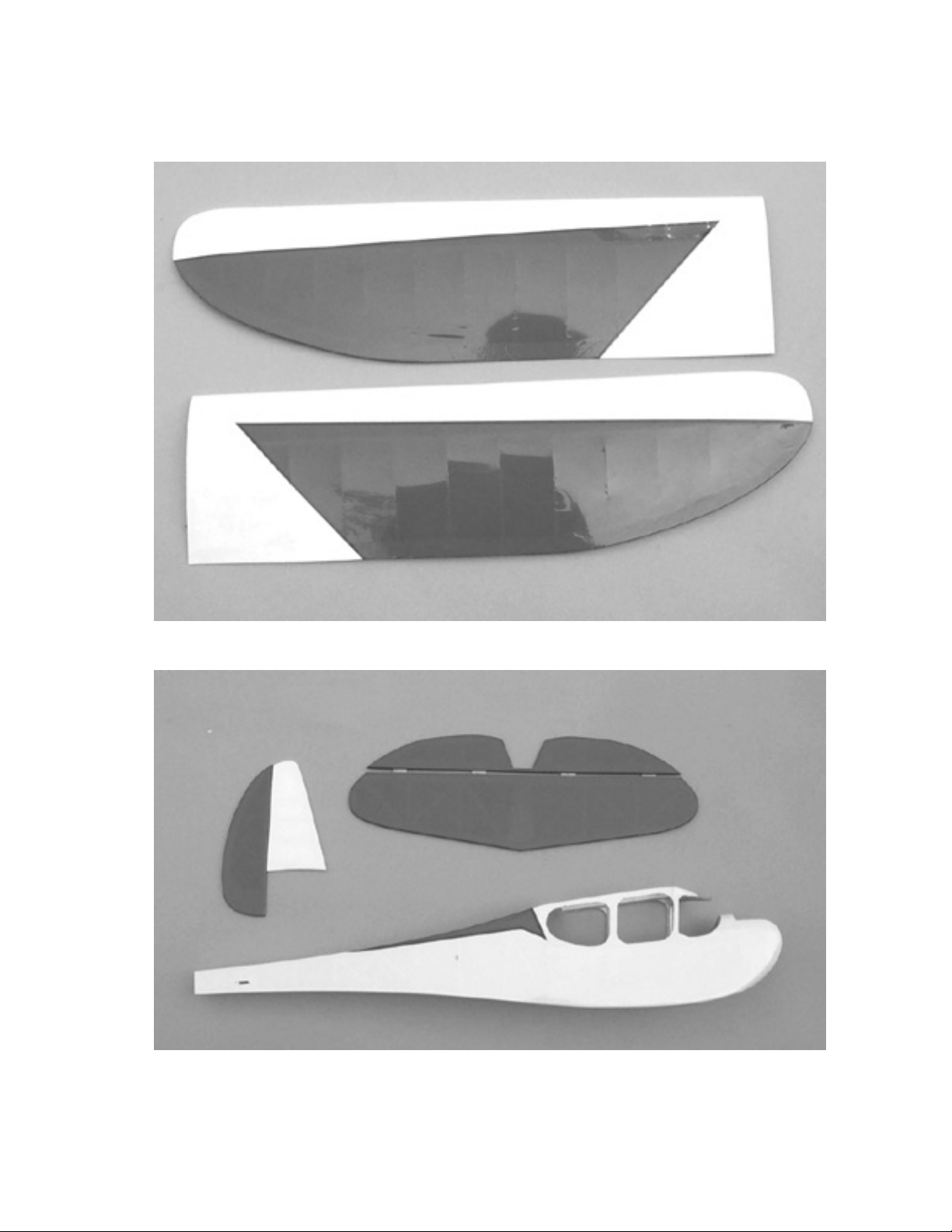
Parts Identification
Wing Panels
Fuselage, Stabilizer/elevators, & Fin/rudder
2
Page 3
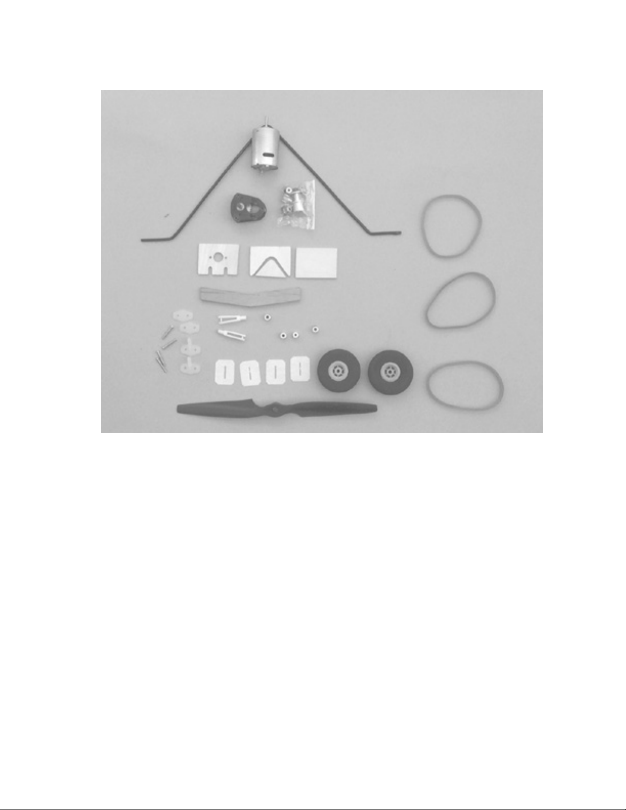
Included Hardware
Speed 400 motor
Gearbox with 3 gear ratios
Propeller
Prop adapter
Main Wheels (2)
Wire Landing Gear
Wire pushrods (2)
Nylon Clevis (2)
Nylon Control Horns (2)
CA Hinges
Wheel Collars (4)
Nylon EZ Clips (2)
#64 Rubber Bands
Wing Panels
Fuselage Assembly
Horizontal Stabilizer and elevators
Vertical Fin and rudder
(Wire pushrods not shown).
Material List
Front Clear plastic windshield
Clear Side windows, 2 left and right
Hardwood dihedral brace
Wire tailskid
Additional Items Required
5-minute epoxy
30-minute epoxy
Medium CA glue
Thin CA glue
Canopy glue
Xacto knife with #11 blade
Masking tape
Small square
15-amp speed control
Radio Equipment
3
Page 4
Wing Construction
We begin construction with the
wing. Before starting construction, it is
a good idea to place wax paper on the
building surface to prevent gluing the
wing to the building board.
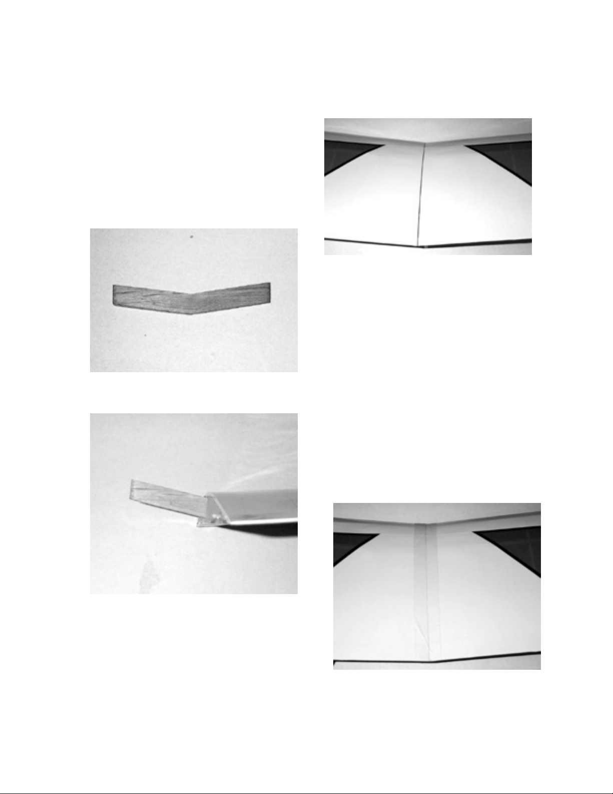
Locate the two wing halves
and the ¼” dihedral brace taped to one
wing panel.
Trial fit the dihedral brace in
one of the wing halves.
When you are satisfied with the
fit, remove the wing panels from the
dihedral brace. Mix about one ounce
of 30-minute epoxy and coat the
inside of the slot in each wing panel,
the dihedral brace, and the root rib of
each wing.
Now slide the dihedral brace
into one wing panel. Wipe away any
excess epoxy that may have oozed
out from inside the slot. Slide the
other wing panel onto the brace,
wiping away any excess epoxy with
a paper towel wet with alcohol. Tape
in place with masking tape until the
epoxy has cured.
Now slide the other wing panel
onto the dihedral brace until it meets
the other wing root. Check for
alignment. If necessary, slightly sand
the corners of the dihedral brace for
proper fit.
When the epoxy has cured,
remove the masking tape and set the
4
Page 5
wing aside. The wing assembly is
now completed.
Tail Construction
Locate the horizontal stabilizer,
elevator, fin & rudder. Notice that
the hinges are installed but not
glued.
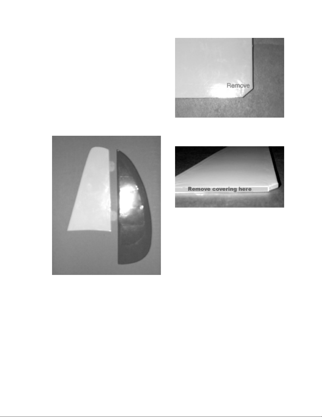
Next, with a sharp #11 Xacto
Blade, remove the covering from the
bottom of the fin.
Remove the rudder from the
fin. At the rear bottom edge if the
fin, it is necessary to remove the
corner with a razor blade to allow
clearance for the elevator. ¼ inch in
and ¼ inch up is enough.
Locate the fuselage and the
stabilizer. Use masking tape on top
of the stab and measure from each
tip to locate the centerline of the
stab. Place the stab on top of the
fuselage and center it using the
marks on the masking tape as a
guide. Check the alignment, and
temporarily tape it in place with
masking tape. The trailing edge of
the stab should be inset ¼” from
the rear of the fuselage.
5
Page 6

Mark the top of the fuselage
where the leading edge of the stab is
located. Now turn the fuselage over
and mark the stab along the fuselage
sides.
Remove the stab from the
fuselage and very carefully with a
#11 Xacto blade remove the
covering between the lines. By
removing the covering you are
gluing to the wood and not the
covering, giving you a much stronger
joint. Cut about 1/16” inside the
lines. Be careful not to cut the wood.
Now carefully remove the
covering at the rear of the fuselage.
Be careful not to remove the
covering too far in front of the stab.
Mix a small amount of 30 minute epoxy and spread a thin coat
on the exposed area of the stabilizer.
Carefully place the stab on the
fuselage and again tape in place.
Make sure it is square with the
fuselage and level with the wing
saddle. Set aside until the epoxy is
dry.
6
Page 7

Using the fin as a guide, mark
the top of the stabilizer so you will
know where the front edge of the fin
stops. (Notice that the notch you cut
earlier is flush with the trailing edge
of the stab, which is ¼” in from the
rear of the fuselage.)
Using a straight edge, draw a
line down the center of the stab from
the mark you just made to the
trailing edge of the stab. Remove the
covering 1/16” out on each side of
the centerline. Be careful not to
remove the covering forward of the
front of the fin.
Mix a small amount of 5minute epoxy and spread a thin coat
on the stab where you removed the
covering. Using a square, set the fin
in place and hold with masking tape
until dry. The front of the notch in
the fin you cut earlier should be even
with the rear of the stab.
Locate the elevator and four (4)
hinges.
Install the hinges in the pre-cut
slots in the elevator and slide them
into the slots in the stab trailing edge.
Leave about a 1/32” gap (a
matchbook cover makes an ideal
gauge). Apply 2-3 drops of thin CA
glue to both the elevator and stab
side of all the hinges. When the CA
is dry, flex the elevator back & forth
to loosen it up.
7
Page 8

Next, install the rudder using
the method described above. Make
sure the elevator does not bind on the
rudder before you glue the hinges.
(Note, your kit may differ slightly
from the prototype from which this
manual was written. Your pieces
may already be assembled, in which
case you only need to glue the gear
to the pre-assembled plate and epoxy
it to the firewall.)
Locate the wood landing gear
mounting pieces and the wire
landing gear.
Remove a ¼” triangle from the
rear of the stab platform, just like
you did the bottom of the fin.
Now CA the rudder hinges on
both sides. The tail section is now
finished.
Fuselage Construction
8
Page 9

Trial fit the gear mounting
plate in the nose of the fuselage. It
should be flush with the bottom of
the fuselage and snug with the
former. You may have to sand the
edges slightly for a good fit.
When you are satisfied with the
fit, epoxy in place with 5-minute
epoxy.
When the epoxy is dry, tack the
landing gear in place with medium
CA glue.
Next trial fit the cover plate. A
little sanding of the edges may be
needed for a good fit. Epoxy in place
with 5-minute epoxy, using the
epoxy to fill in any gaps between the
landing gear and the mounting
plates. Set the assembly aside until it
is dry.
Next trial fit the filler plate.
Again slight sanding may be needed
for a snug fit. When you are satisfied
with the fit, epoxy in place with 5minute epoxy.
Next locate the two main
wheels and four wheel collars. Install
the wheels onto the main gear, using
9
Page 10

two wheel collars on each side.
Make sure the wheels turn freely.
Next, at the rear of the fuselage
under the stab, you need to cut away
the covering for the pushrod slots,
one on each side.
to locate the elevator and rudder
control horns. Mount the control
horns with the two #2 screws and
nylon backing plate from the parts
pack.
(Note: It may be necessary to put a
slight “Z” bend in the pushrod like
shown above to make it operate
smoothly.
Now it is time to install the
servos. We used the Maxx Products
MX-50 servos in the prototype.
Locate the two 1/8 x ¼ x 2-1/4
spruce servo rails.
Locate the two wire pushrods
and the nylon clevis. Install a clevis
halfway onto the threaded end of
each pushrod. Slide the pushrod into
the openings and use them as a guide
10
Use your servo as a spacer and
glue in the two servo rails using 5minute epoxy.
Page 11

Next, using the hardware
supplied with the servos, mount them
to the servo rails.
Next, center the elevator and
rudder and secure them with
masking tape.
Center the servo arms and
make a 90° bend in the rod. It may
be necessary to cut off some of the
excess rod. Using two keepers from
the hardware pack, attach the
pushrods to the servo arms.
Motor Installation
Prior to installing the motor, it
is necessary to hook up the speed
control. We used the Maxx Products
# MX-9115. Follow the instructions
supplied with your speed control
prior to installing the motor in the
airplane.
Locate the motor and gearbox.
There are three gear ratios. We used
the middle gear (2.5 to 1), but you
can experiment to get the
performance you prefer.
11
Page 12

Slide the gear on the motor
shaft and secure with the set screw.
Use the gearbox as a guide to set the
proper location on the shaft.
Next, attach the motor to the
gearbox using two of the supplied
screws. Cut a ¼” wide strip of
magazine page to use as a gauge for
the gear spacing. The gears should
be snug but not bind.
(Note: Trial fit the prop on the
adapter and ensure that the prop
clears the nose. If it doesn’t, break
the firewall loose, shim it out for
proper prop clearance and re-glue.)
Install the prop on the adapter
and tighten.
Next, mount the motor to the
firewall. You may have to enlarge
the center hole slightly for the prop
adapter to clear.
12
Locate the front windshield and
trial fit. It may be necessary to trim it
slightly for a good fit. Apply a thin
bead of RC56 Canopy Glue® along
the edge of the windshield and tape
in place with masking tape overnight
to dry.
Page 13

Next install the side windows.
They have been pre-cut but slight
trimming may be necessary. When
you are satisfied with the fit, apply a
thin bead of RC56 Canopy Glue®
around the edge of the window
frames and insert the windows. Tape
in place if necessary and allow the
glue to dry overnight.
Finishing The Model
Now all that’s left is to install
the receiver and battery pack. We
used an eight-cell 1100ma square
pack (Maxx Products #8KR1100AAU) wrapped in foam rubber
directly behind the motor, with the
receiver and speed control just to the
rear of the battery.
With All radio gear and battery
pack installed, the model should
balance 2- 3/8” behind the leading
edge of the wing measured at the
fuselage, or just slightly behind the
wing spar.
Follow your radio
manufacturer’s instructions for
setting up your radio. Set the
elevator throw for up/down 3/8” and
the rudder throw left/right ¾” for the
initial flights. You may wish to
adjust the throws further after the
first few flights. Be sure to use a
minimum of 4, preferably 6 #64
rubber bands to secure the wing on
the fuselage.
1/2A Conversion
For those of you who wish to
fly the Lightnin’ Bug with one of the
fine 1/2A glow motors, we have
included a firewall for mounting the
motor. It is a laser cut piece of 1/8”
lite plywood. The vertical center line
and thrust line are marked.
13
Page 14

Mount your 1/2A motor on the
firewall, using the laser-etched lines
as a guide. You will need 4 #2 x 3/8”
wood screws (not supplied).
Remove the motor from the
firewall and epoxy the firewall to the
front bulkhead using 5-minute
epoxy.
When the 5-minute epoxy has
cured, coat the entire engine
compartment with 30 minute epoxy
to fuel proof the bare wood.
Now re-mount the motor to the
firewall and make sure the prop will
clear the nose of the airplane.
14
 Loading...