

Page 1
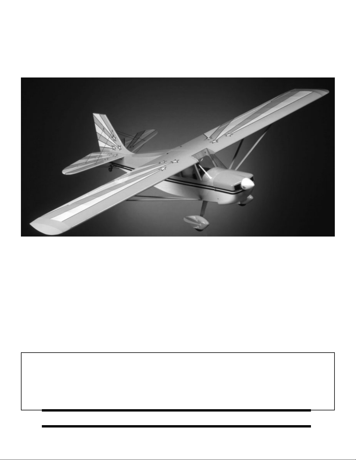
Aerobatic flying just doesn't get any better than this Decathlon ARF. Its clean lines, long tail moment, and
superb wing design will reward you with the maneuvers you love - knife edge, split S, lumcevac, torque rolls,
snaps, and ground-hugging inverted flight. What's more, we've engineered this ARF to get you into the air with
a minimum of fuss. So take a few minutes to carefully read the introductory material and then get to work. You'll
soon be out at the field with a classic aerobatic champion!
WARNING
A radio-controlled model is not a toy and is not intended for persons under 16 years old. Keep
this kit out of the reach of younger children, as it contains parts that could be dangerous. A radiocontrolled model is capable of causing serious bodily injury and property damage. It is the buyer's
responsibility to assemble this aircraft correctly and to properly install the motor, radio, and all other
equipment. Test and fly the finished model only in the presence and with the assistance of another
experienced R/C flyer. The model must always be operated and flown using great care and common
sense, as well as in accordance with the Safety Code of the Academy of Model Aeronautics
(www.modelaircraf t.org). We suggest you join the AMA and become properly insured prior to flying this
model. Also, consult with the AMA or your local hobby dealer to find an experienced instructor in your
area. Per the Federal Communications Commission, you are required to use only those radio frequencies specified "for Model Aircraft."
LIMITED WARRANTY
Carl Goldberg Products, Ltd. has inspected and certified the components of this aircraft. The comp any urges the buyer to perform
his own inspection, prior to assembly, and to immediately request a replacement of any parts he believes to be defective for their
intended use. The company warrants replacement of any such components, provided the buyer requests such replacement within a period of one year from the date of purchase and provided the defective part is returned, if so requested by the company.
No other warranty, expressed or implied, is made by the company with respect to this kit. The buyer acknowledges and understands that it is his responsibility to carefully assemble the finished flying model airplane and to fly it safely. The buyer hereby
assumes full responsibility for the risk and all liability for personal or property damage or injury arising out of the buyer's use of the
components of this kit.
DDEECCAATTHHLLOONN AARRFF
Pt. #2017 3/01
CARL GOLDBERG PRODUCTS, LTD.
P.O. Box 818 Oakwood GA 30566 Phone #678-450-0085 Fax # 770-532-2163 www.carlgoldbergproducts.com
© Copyright 2001 Carl Goldberg Products LTD.
Page 2

ITEMS NEEDED TO COMPLETE THIS AIRCRAFT
! 1 RADIO GUIDANCE SYSTEM (4 CHANNEL
MINIMUM REQUIRED WITH 5 SERVOS)
! 2 12” AILERON SERVO EXTENSION WIRES
! 1 Y-HARNESS
! 1 ENGINE .61-.75 2-CYCLE, .70-.91 4-CYCLE
AND MUFFLER
! 1 CAACCELERATOR
! 1 2 OZ. BOTTLE CA MEDIUM GLUE
! 1 1/2 OZ. BOTTLE CA THIN GLUE
! 1 20 MINUET EPOXY
! 1 1/4” FOAM RUBBER
OPTIONAL:
! 1 1/6 PILOT FIGURE
! 1 SWITCH HARNESS
NOTE: The Decathlon ARF covering matiches
Cub Yellow(#884), Midnight Blue(#885)
and White (#870) UltraCote®.
UltraCote® is a registered trademark of Horizon Hobby Distributors
TOOLS AND SUPPLIES FOR ASSEMBLY.
! MODELING OR UTILITY KNIFE
! WORK SURFACE (24" X70")
! ELECTRIC DRILL
! 1/16”, 3/32”,1/8", 3/16”, 5/32”, 1/4”, 5/64”
7/32” DRILL BITS
! SMALL STANDARD & PHILLIPS SCREW-
DRIVERS
! MASKING TAPE
! NEEDLE NOSE PLIERS
! MOTO TOOL
! 24” RULER
! FLEXIBLE STRAIGHT-EDGE
! 30-60-90° x 6" TRIANGLE
! SOFT PENCIL
! A FEW STRAIGHT OR "T" PINS
! ADJUSTABLE WRENCH
! WIRE CUTTER (DYKES)
! OPTIONAL HEAT GUN/COVERING IRON
! ACID BRUSH
! ELECTRICAL TAPE
! SOLDERING IRON, FLUX, SOLDER
! PIECE OF MEDIUM SANDPAPER
! 5 FT. LENGTH OF STRING
2
Page 3

INTRODUCTION
3
USING THIS INSTRUCTION MANUAL
Before you begin assembling your DECATHLON ARF,
take some time to read through this entire instruction
book. It is designed to take you step-by-step through the
process and to give you added information on engine and
radio selection and set-up, balancing your aircraft, and flying your model. The time you spend will speed the
assembly process and help you avoid problems.
PREPARING FOR ASSEMBLY
You will need a work area of approximately 24 x 70" which has
been covered to protect it from adhesive, as well as cuts a n d
other damage. Many people cover their work area with a
sheet of dry wall (sheet rock) and/or waxed paper to prevent CAGlue and Epoxy from ruining the work surface.
CONSTRUCTION TIPS
IMPORTANT: ALWAYS READ A FEW STEPS AHEAD.
This will alert you to coming instructions and will help you
plan accordingly.
Using the Parts Identification section, familiarize yourself
with the various items included in your kit box.
As you work, CHECK OFF EACH STEP in the box provided, so that you are sure you do not forget anything.
Do not hesitate to ask questions. Your local hobby dealer
and area flyers will most likely be happy to help, as they
want you to have a successful flying experience. You may
also receive technical assistance from Carl Goldberg
Products, Ltd. via e-mail (questions@carlgoldbergproducts.com) or by telephone 1-678-450-0085.
ADHESIVES & GLUING TECHNIQUES
CAadhesives are specially formulated to firmly glue the
plywood, hardwood, and balsa used in your model and to
withstand the vibration and stresses of high performance
flight. However, there are times, such as when you are
installing the stabilizer and fin on the fuselage and want
more set-up time for careful alignment and positioning,
then you should use epoxy.. Occasionally, you also will
want to use thin CA, which "wicks" into the surrounding
areas. Aliphatic resin glue or similar water-based glues
can also be used, but they will add to the assembly time
because they dry so much more slowly than CA glue.
Remember, whenerever using any CA, you must be careful to read instructions thoroughly, as you will have only
seconds for positioning of parts. Be sure to trial fit parts
together before gluing. Also, never use watery THIN type
CA glue for gluing plywood and hardwood parts. Thin
CA's do not adequately bond these areas.
CAUTION
Some people may experience an allergic reaction when
exposed to fumes from CA glue or epoxy. As with paints,
thinners, and solvents, it is always important to use glues
only where there is adequate ventilation to carry fumes
away. Afan is recommended. Also, special care must be
taken when using CA, as it will bond skin as well as other
surfaces. Before using any CA, carefully read all label
precautions. When using CA, protective eye-wear and
care in keeping the glue away from the face is highly recommended. If CA does happen to get into the eye, hold
lid open and flush with water only. Seek immediate medical attention.
COVERING
The DECATHLON ARF is covered in a premium polyester film chosen by many of the world's top flyers for its
beauty, toughness, and ease of application and repair. It
is not uncommon for ARF's to develop a few wrinkles in
transit. If this is true of your model, the situation is easily
corrected. Before you begin putting the pieces together,
run over the surface of each section with an iron (either
specially designed for airplane use or the more cumbersome household iron) or use a modeling heat gun. Apply
the heat (set at about 350° F), following along with a soft
cloth and pressing down on the covering as you go
around. This will more firmly set the covering adhesive
into the wood and keep your aircraft covering tight and
smooth in the future.
One of the great advantages of polyester film is that it can
be applied over itself without causing gas bubbles. This
allows you to repair your aircraft, as well as to customize
it in a number of ways. If, due to a flight mishap, you get
a hole or similar covering damage, simply trim away the
ragged edges and then apply a patch, following the directions that come with your covering , which is available at
your hobby dealer.
Page 4
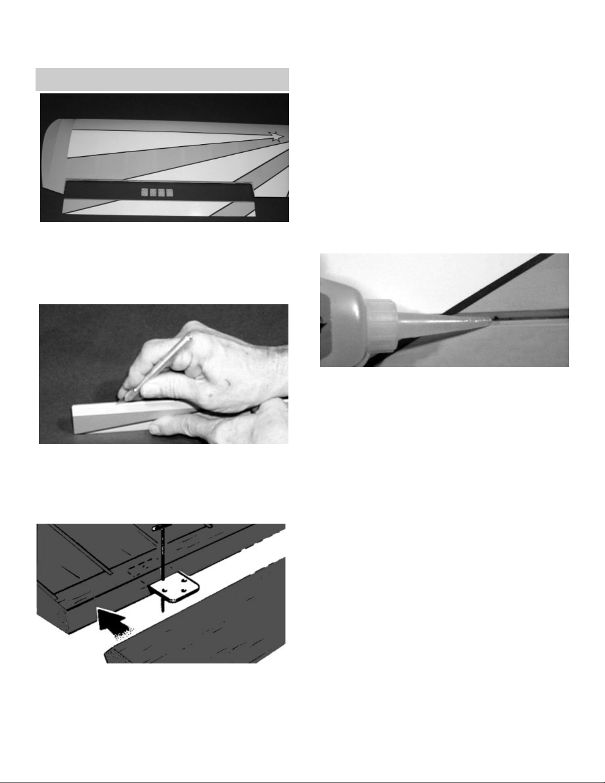
1. ! Collect the following parts:
(1) Left wing
(1) Right wing
(1) Left aileron
(1) Right aileron
(8) Jet hinge
2. ! Locate the pre-cut aileron hinge slots in both
wing halves. Using a hobby knife (#1 1 blade),
slide the blade into each slot to make sure it
is cleanly cut.
! Repeat this process with the ailerons, mak-
ing sure all hinge slots are clean.
3. ! Place a straight pin into the center of each of
the four JET™ hinges.
! Slide each hinge into the hinge slots on one
of the wing halves. The pin will prevent the
hinges from going further than halfway into
the wing.
! Slide the aileron toward the wing until no
gap remains between the aileron and the
wing.
5.
! Carefully check the alignment of the aileron.
It should be centered, with about 1/32" on
either end.
! When satisfied with the alignment, remove
the straight pins, being sure to keep the
aileron tight to the wing. You may wish to
apply a few pieces of masking tape to keep
the pieces in place.
6. ! Keeping the aileron and wing in position,
apply 3 or 4 drops of thin CA glue to the
small exposed area of each hinge.
! Turn the assembly over and again apply 3
or 4 drops of thin CA glue to the exposed
hinge surfaces.
! Allow to dry for 10 minutes before flexing
the aileron.
7.
! Repeat the above steps for the other half of
the wing.
WING ASSEMBLY
AILERON INSTALLATION
4. ! Select the aileron for the wing on which you
are working and insert the exposed half of
each hinge into the aileron slots.
4
Page 5
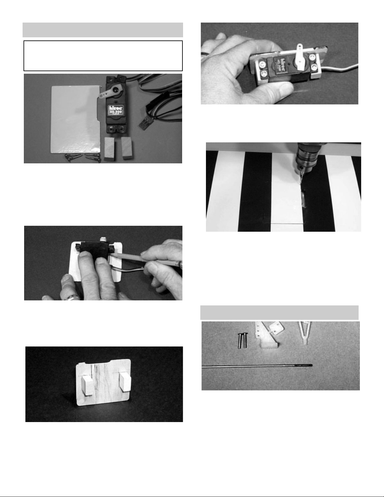
AILERON SERVO INSTALLATION
Note: The following pictures may not exactly match
the hardware you are using. Always check the radio
manufacturer's instructions when installing radio
equipment.
1. ! Collect the following items:
(1) Aileron servo door
(2) 3/8 x 3/4" Servo mounting block
(4) Servo mounting screw (supplied with radio)
(4) #2 Washer
(4) #2 x 3/8" Screw
(1) Servo with rubber grommet
2. ! With the servo door upside down on the work
surface, place the servo on top of the door
with the servo arm post centered vertically
and horizontally with the servo door notch.
! Mark the location of the servo, as shown.
! When the epoxy is dry, drill 1/16" holes into
the servo blocks and, using the screws supplied with the radio, mount the servo onto the
blocks.
4. ! Place the servo door on the wing and drill a
1/16" hole on each corner.
! Using the #2 x 3/8" screw and #2 washer
supplied with this kit, screw the door to the
mounting plate.
5.
! Repeat the above steps for the second
aileron servo.
5
3. ! Remove the servo from the door.
! Spread epoxy on the servo mounting blocks
and, making sure the wood grain on both
mounting blocks runs vertically, glue the
blocks in place along the marks just made.
AILERON CONTROL HORN INSTALLATION
1. ! Collect the following items
(2) Large control horn with back plate
(4) 2-56 x 3/4" screw
(2) 1/16 x 7" threaded wire
(2) Snap link
(1) Nylon snap nut (molded 6-up)
Page 6
IMPORTANT! To ensure that any connections locat-
ed inside the wing will not come loose, either when
the wires are pulled, or during flying, always tape
them securely together with electrical tape.
3. ! Making sure to use the correct servo for the
opening, attach the servo wire to the 12"
extension and securely tape the connection.
! Push the extension wire into the tube in the
wing until it comes out the hole near the center of the wing.
4.
! Grasping the extension in the hole, SLOWLY
pull until the end of the 12" extension comes
out of the hole.
2. ! With the aileron servo door in place, make a
mark at a 90º degree angle to the trailing
edge and in line with the servo arm.
3. ! Position the control horn so that the snap
link holes are on the mark just made and
right next to the hinge line, as shown.
4.
! Using a 5/64" drill bit, make a pilot hole in
each screw location.
! Mount the control horn with the 2-56 x 3/4"
screws.
5. ! Thread the 1/16 x 7" rod onto the snap link.
Make sure the rod shows in the center of the
snap link.
! Place the snap link in the second hole from
the top on the control horn.
6. ! Making sure the aileron is in neutral (level)
position, mark where the wire meets the hole
on the servo arm.
! Remove the wire and cut it about 1/2"
beyond the mark.
! Make a 90º bend (or a "z" bend, if preferred)
in the wire and insert the wire in the servo
arm.
6
SERVO EXTENSION INSTALLATION
1. ! Gather the following items:
(2) 12" Extension wires
(1) Right and left wing halves
2. ! Remove the servo door and plug one 12"
extension wire into the servo.
! If the extension is not long enough to reach
to the center of the wing, add an additional
extension to each extension wire for correct
length.
1/16"
! Secure the wire with a snap nut and then put
a drop of CA glue™ on the snap nut to make
sure it stays in place. Do not glue the snap
nut to the servo arm.
Page 7
2. ! Using epoxy, mount the 5/16 x 1-3/4” dowels
into the holes in the notch of the leading edge
of the wing. Make sure to leave about 1/2” of
dowel sticking out of the front of the wing. You
may wish to slightly taper the exposed dowel
ends for ease of insertion into the fuse holes.
NOTE: If the covering on your wing has loosened in
transit, refer to the covering section of the
"INTRODUCTION" before continuing.
1. ! Collect the following items:
(1) Right wing
(1) Left wing
(2) 5/16 x 1-1/2" dowel
(1) 7/8” x 21-3/4” aluminum tube
MOUNTING WING TO FUSELAGE
3. ! Insert a 8-32 blind nut into each hole in the
wing mounting block, with the teeth pointing
upward into the blocks.
! Temporarily insert a 8-32 x 1" screw with a
washer into each hole on the other side of
the mounting block and draw the blind nut
teeth up into the wood.
! When the blind nuts are firmly seated in the
wing mount blocks, remove the screws.
4. ! Gently prodding the covering, locate the hole
next to the center of the of the wing, close to
the trailing edge.
! Carefully remove the covering OVER THE
HOLE in the wing on both the top and the
bottom.
! Next, locate the holes in the wing bolt plate
and again, carefully remove the covering
over the holes.
! Do the same to the other wing panel.
5. ! Insert the aluminum tube into one wing half
and push the tube into the wing until it stops.
Then insert the other wing half onto the tube
and slide the wing halves together.
! Tilt the leading edge of the wing down into
the fuselage and insert both dowels in the
holes that are in the front of the fuselage
! Insert a 8-32 screw with a washer into each
hole in the wing bolt pad and then insert each
screw into the holes near the trailing edge of
the wing.
! Tighten both screws down until they are tight.
5. ! Repeat these steps for the other half of the
wing, so that both servo extensions are exiting the holes near the center of the wing.
7
! Tape the extension securely to the wing, so
that it will not slide back in while you are
working. Screw the servo door onto the wing.
Page 8
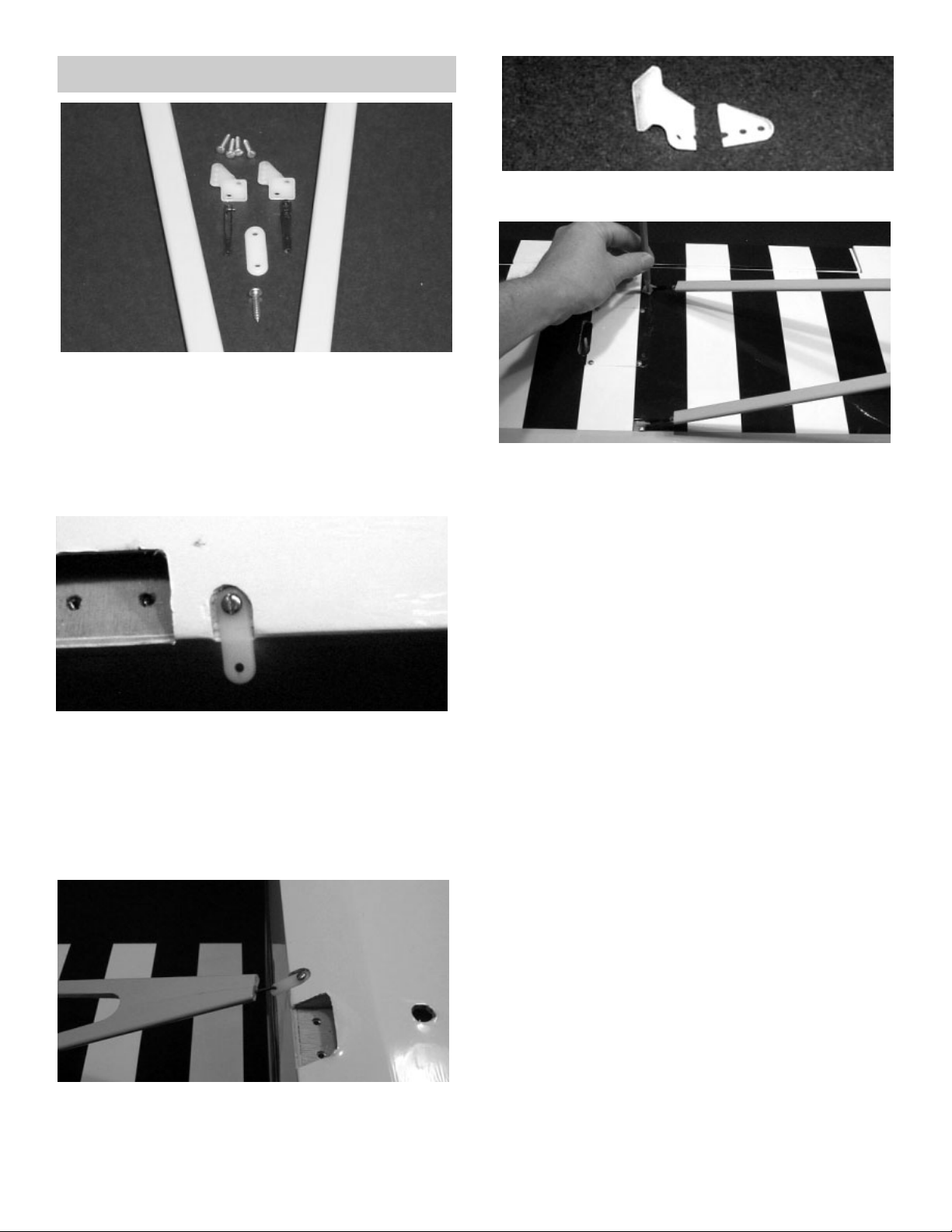
WING STRUT INSTALLATION
1. ! Collect the following parts:
(2) Wing strut
(1) Wing/fuse assembly
(4) Small control horn
(8) #2 x 1/2” Pan head screw
(4) Metal clevis
(2) Nylon straps 7/8” long
(2) #4 x 1/2” Pan head screw
2. ! Place the 7/8” long nylon strap into the notch
behind the landing gear cut out.
! Mark the hole location and drill a hole using a
3/32” drill bit.
3.
! Mount the strap onto the fuselage using a
#4 x 1/2” pan head screw.
! Repeat for the other side of the fuselage.
4. ! Place the wing strut onto the nylon strap.
NOTE:The short front of the strut should be parallel
with the front of the wing. In the above photo
the short side is in front.
5. ! Modify the small control horns by cutting, as
shown above.
6. ! Thread the metal clevis onto the threaded
wires at the outer end of the strut until the
wire protrudes into the center of the clevis.
! Install the modified control horns onto the
clevis at the end of the strut.
! Mark the modified control horn hole locations
onto the wing.
NOTE:Keep the front strut parallel to the leading
edge of the wing.
7.
! Drill the control horn holes, using a 1/16”
drill.
! Screw the modifiedcontrol horns to the wing,
using #2 x 1/2” pan head screws.
! Repeat these steps for the other strut.
8. ! Remove both struts when completed.
8
Page 9
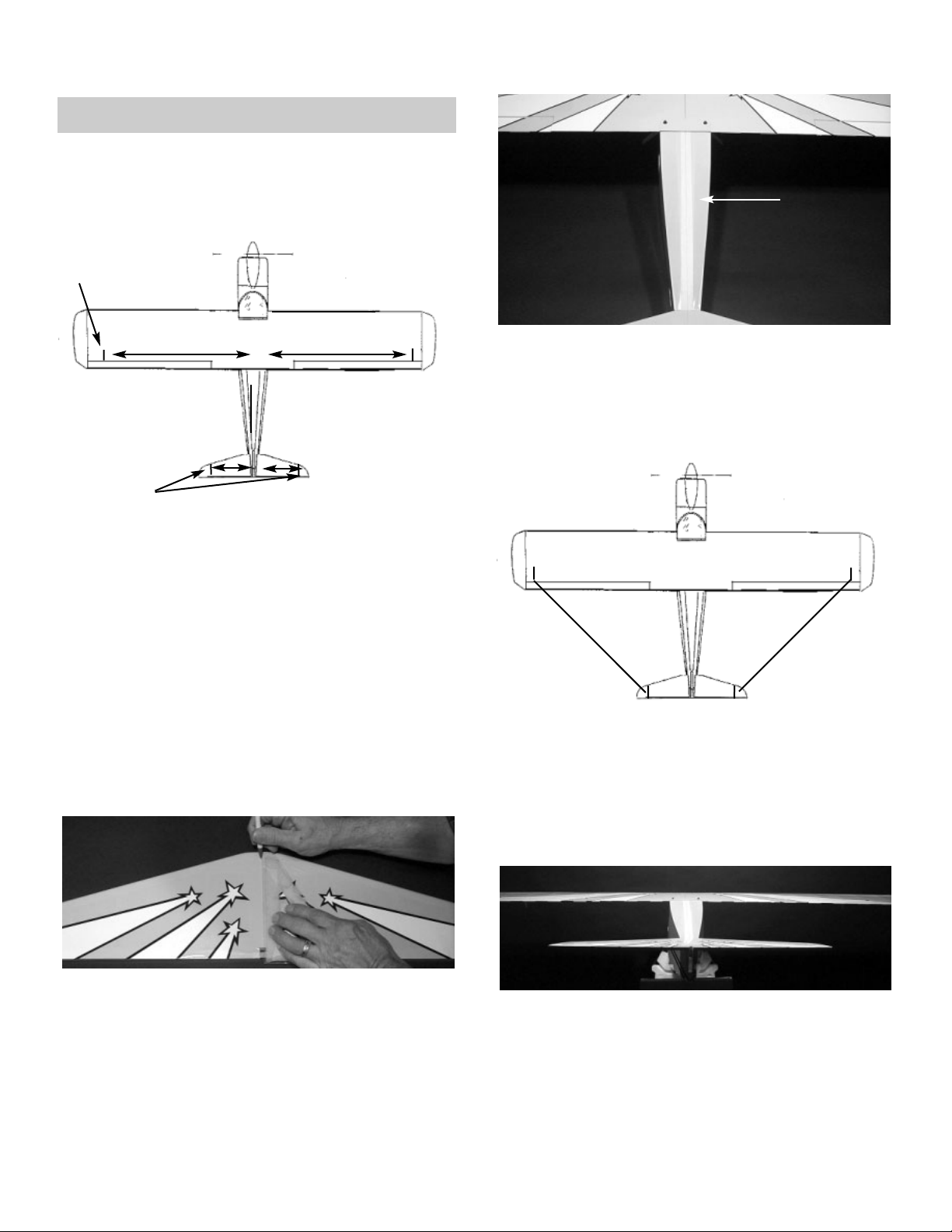
TAIL ASSEMBLY
STAB INSTALLATION
1. ! Collect the following parts:
(1) Stabilizer
(1) Wing/fuse assembly
3. ! Place a piece of masking tape on each wing
tip, just above the aileron hinge line, as
shown above.
! Measuring out from the center joint of the
wing,make a mark on the tape at 35-1/2".
Repeat for the other side of the wing
4.
! Place two strips of masking tape along the
edge of the stab, next to the outer stab tips
and above the hinge line.
! Measure the total length of the stab along the
hinge line and locate the centerline with a
mark.
! Measure 13-1/2” out from the centerline and
make a mark on the masking tape on both
the left and the right side of the stabilizer.
5. ! From the center point on the stab, draw a vertical line up to the top of the stab.
! Place masking tape on the top of the fuse,
just in front of the stab.
! Measure and mark the centerpoint on the
tape.
! Mark a centerline on the fuselage, just behind
the wing.
! Place a piece of masking tape along the top
of the fuselage, as shown, and draw a line
from the center mark in front of the stab up to
the center mark below the wing.
6. ! Place the stab on the platform with the center of the stab lined up with the centerpoint
on the fuse.
! Measuring from the mark on each wing tip to
the mark on the stab tip, make sure the distance "X" on the right side is the same as the
distance on the left side.
7. ! Check to see that the stab is level (parallel)
with the wing. If necessary, insert paper strip
shims to achieve proper alignment.
35-1/2"
TAPE
TAPE
35-1/2"
13-1/2"
13-1/2"
9
TAPE
x
x
Page 10

8. ! When satisfied with the alignment of the
stab, temporarily tape it securely in place.
! Mark the area on the bottom of the stab
where it rests on the fuse.
! Remove the stab from the fuse and, working
1/4" inside the drawn lines, carefully remove
the covering from the bottom of the stab. BE
CAREFUL TO AVOID CUTTING THE
WOOD.
9.
! Spread epoxy on both the bottom of the stab
and the stab platform of the fuse.
! Replace the stab on the platform and, after
again checking the alignment of the stab to
the wing, allow the epoxy to dry thoroughly.
FIN INSTALLATION
1. ! Slide the fin mounting post into the rear of
the fuselage.
! Check the fit. The fin should fit easily into
the slot at the rear of the fuselage and the
notch in the rear of the stab. The fin should
stand upright by itself. Enlarge the notch, if
necessary.
! TAKING CARE NOT TO CUT INTO THE
WOOD STRUCTURE UNDERNEATH, and
working inside the drawn lines, carefully
remove the covering where the fin mounts on
the fuse and stab.
4. ! When satisfied with the fit, mark the location
of the fin on the fuse and stab by drawing a
line on both sides of the fin, as shown.
REMOVE SHADED
AREA
5. ! Remount the fin on the fuse and, using a 90º
triangle, make sure the fin is perpendicular
to the stab.
! When satisfied with the fit, remove fin and
mix up a couple of spoonfuls of epoxy.
! Apply a THIN, even coat of epoxy on the bot-
tom of the fin and along both sides of the fin
mounting posts. Avoid too much glue, which
will squeeze out from underneath the fin.
! Mount the fin on the fuse and place the tri-
angle against the fin to make sure it is perpendicular.
! Use masking tape to secure the fin and tri-
angle in position until the epoxy is thoroughly dry. Make sure not to glue the triangle!
10
Page 11

RUDDER & ELEVATOR CONTROL HORN
INSTALLATION
1. ! Collect the following items:
(1) Rudder
(1) Elevator
(2) Control horn
(4) 2-56 x 3/4" machine screw
(1) Double sided control horn
(1) 2-56 x 1/2” philups head screw
2.
! Measuring from the fuselage side, make a
mark on the elevator hinge line 5/8" from the
fuse.
3. ! Place the center of the control horn on the
mark and the hinge line and mark the location of the screw holes on the elevator.
! Using a 5/64" drill bit, drill the holes through
the elevator.
! Using two 2-56 x 3/4" screws, screw the
control horn and the backplate tightly to the
elevator.
! Repete these steps for the other elevator.
NOTE:The double-sided control horn may be found
in the tailwheel assembly package.
4. ! Place the control horn in the rudder notch, as
shown. The control horn must be even with
the hinge line. When you are satisfied with
the fit, mark the location of the screw hole
and drill, using a 3/32” bit.
! Mount the control horn, using the 2-56 x 3/4”
phillips head screw.
RUDDER & ELEVATOR INSTALLATION
1. ! Collect the following items.
(1) Fuselage/Tail Assembly
(2) Elevators
(1) Rudder
(12) Jet hinges
3. ! Remove the pins in each hinge and, keeping
the elevator/stab assembly in position, apply
3 or 4 drops of thin CAto each hinge, on both
the top and bottom sides of the stab.
! Allow ten minutes for the CA to cure before
flexing the elevator. Then install the second
elevator.
2. ! Take four hinges and, as with the aileron
hinge installation, insert the hinge into the
elevator, using straight pins to ensure the
hinge stays centered between the stabilizer
and the elevator.
! Slide the exposed side of the hinge into the
slots in the stab until the pins touch both the
stab and the elevator.
4. ! When the elevators have cured, install the
hinges and mount the rudder, using the same
techniques used for the other hinged surfaces.
NOTE:Before gluing, make sure the top of the rud-
der is even with the top of the fin.
11
Page 12

LANDING GEAR INSTALLATION
NOTE: The tailwheel might be different than shown in
your kit.
1.
! Collect the following parts:
(2) Landing gear
(6) 6-32 x 1/2” Socket Head Screw
(6) #6 Washer
(6) 6-32 Blind Nut
(1) Tail wheel
(2) 4-40 x 1/2” Phillips head screw
(2) Springs
2. ! Locate the three holes under the covering on
the bottom rear of the fuselage. Remove the
covering from all three holes.
NOTE:The hole nearest to the nose of the model is
the exit hole for the receiver antenna. The other two
holes are for the tailwheel assembly.
3. ! Mount the tailwheel using the 4-40 x 1/2”
phillips head screws, as shown above. Hook
the springs between the rudder control horn
and the tailwheel bellcrank. It may be necessary to open the end of the springs in order
to connect them to the control horns and the
bellcrank.
4. ! Working on one landing gear leg at a time,
place the gear in the bottom of the fuselage,
as shown.
! Align the holes in the landing gear and the
fuselage.
5.
! Insert a 6-32 x 1/2” socket head screw with a wash-
er into each hole
! With the screws and the washers through the
gear, reach inside the fuselage and thread on
a 6-32 blind nut.
6.
! First place a blindnut on each of the screws,
and then tighten down each of them.
! Repeat for the other side of the landing gear.
FUSELAGE ASSEMBLY
SERVO INSTALLATION
1. ! Collect the following items:
(2) 1/4 x 3/8 x 1” servo block
(3) Radio servo
(12) Servo mounting screw
2. ! Test fit to make sure the servos fit snuggly in
the servo tray. Shim or sand, if necessary to
achieve correct fit.
3.
! Glue the servo blocks at each end of the mid-
dle servo hole.
12
Page 13

4. ! Mount the servos as shown above.
Note: To make mounting the rear servo easier, drill a
small hole in the wing mounting block.
1. ! Collect the following items:
(2) 34” stranded cable
(4) 1/16 threaded couplers
(4) Snap-links
(2) 1/8 x 24” nylon tubing
! Now, making sure the cable is all the way
into another threaded coupler, solder it to the
cut end. The total length of the finished cable
should be 24”.
! Repeat the above steps to make a second
cable to the same length.
! Wash the soldered coupler/cable assembly
with soap and water.
4.
! Install the cables by using the guide tubing
and threading them through the fuselage, as
was done with the elevator pushrod.
6. ! Connect two snap links to the center servo,
as shown, and the other two snap links to
the rudder control horn.
! When the cables are connected test the
tightness by moving the rudder by hand. The
rudder should have very little movement
without moving the servo.
RUDDER CABLE INSTALLATION
2. ! Using flux and silver solder, solder a thread-
ed coupler onto the end of the cable.
3.
! From the coupler end, and including the cou-
pler itself, measure 23 inches and mark the
cable. Then cut it with a wire cutter.
5. ! Place a snap link on each end of each cable.
13
Page 14

ELEVATOR PUSHROD INSTALLATION
1. ! Collect the following items:
(2) .072 x 10” threaded wire
(1) .063 x 6-3/8” wire
(3) Nylon snap link
(1) Single-hole pushrod plug
(1) Double-hole pushrod plug
(1) 36” fiberglass pushrod tube
(2) 1/8 x 24” nylon guide tube
(1) Elevator Wire drawing (Last page in booklet)
2. ! Using a fine-tooth saw or modeling knife, cut
the fiberglass pushrod to a length of 17-3/4.”
This may be accomplished by rolling the
tube under the blade.
3.
! Measure 1” back from one end of the
pushrod and drill a 5/64” hole completely
through both sides. This hole will hold the
elevator wires.
4. ! Measure 1” from the other end of the
pushrod and drill a 5/64” hole HALFWAY
THROUGH the pushrod. TAKE CARE TO
DRILL ONLY THROUGH ONE SIDE.
5. ! Using the 5/64” drill, and holding a pushrod
plug, as shown, drill out the center of the plug
to form a tube. Repeat for the other plug.
6. ! Using the Elevator Wire Drawing, place a
threaded 10” wire over Drawing #1, as
shown.
! Starting at the threaded end, measure back
to the first bend and mark the wire. Then,
carefully bend the wire to match the drawing.
7. ! Mark the second bend and then bend the
wire accordingly.
! Repeat this process for a second threaded
wire.
14
Page 15

12. ! When the bent tip is exiting the hole in the
pushrod and the plug tightly meets the
pushrod, apply CA glue to the joint.
13. ! Insert both of the nylon guide tubes into the
exit holes located closest to the stab on
each side of the model.
11. ! Place the single-hole plug onto the wire and
then bend the wire, as shown.
! Referring to the drawing, cut the wire after the
bend and slide the end of the wire into the
single-hole end of the pushrod.
8. ! With the pointed end of the plug facing the
threaded end of the wired, slide the doublehole plug onto the non-threaded end of the
wires.
! Measure 2-3/8” down from the second bend
and make a 90º bend. Then, cut the wire
after the bend, so that it will fit in the
pushrod.
9. ! Insert the two wires into the double-hole end
of the pushrod until the bent ends slide into
the holes.
! Slide the plug as far as it will go down into
the pushrod. Then, use medium CA to glue
the plug to the pushrod.
10. ! Using Drawing #2 as a template, mark the
location of the bend on the third threaded
wire.
14. ! When the nylon tubes have been pushed
through the fuselage, insert the two wires
from the end of the pushrod into the tubes.
! At this time place snap-r-keeper on the servo
end of the pushrod. Push the snap-r-keeper
towards the fiberglass pushrod. You will
mount the keeper to the servo arm later.
! Then, slide the pushrod back down through
the fuselage, allowing the nylon tubes to
guide the way until the two ends of the
pushrod come out of the exit holes on either
side of the airplane.
15
Page 16

16. ! Thread the snap-links onto each of the wires,
until the the wire shows in the middle of the
snap-link.
17.
! Connect the snap-link to the second hole of
control horn.
18. ! While keeping the elevator level with the
stab, mark where the pushrod wire meets the
servo arm hole.
! Bend the the pushrod up and cut off the end
of the wire leaving 1/2” up.
! Slide the snap-r-keeper towards the servo
and snap onto the wire and around the servo
arm.
15. ! Once the wire has exited the fuselage,
remove the nylon tubing from the end of the
wires.
Motor Mount/Engine Installation
2. ! Using the alignment marks, center the motor
mount on the firewall and tack glue.
REMEMBER, the following pictures and instructions may vary slightly , depending on the equipment
you are using.
1 Collect the following items:
(1) Engine
(1) Motor Mount
(4) 6-32 x 1-1/2” socket head screw
(4) 6-32 Blind nut
(4) #6 Washer
(4) #8 x 1” Pan head screw
(3) 1/4” x 2-3/4” Plywood spacer
ALIGN
MARKS
ALIGN
MARKS
16
Page 17

3. ! Drill a pilot hole through the motor mount,
using a 1/8” drill bit.
! Remove the motor mount and re-drill the
holes, using a 5/32” drill bit.
4. ! Install the motor mount blind nuts into the the
back of the firewall with the 6-32 x 3/4” socket head screw and the #6 washer.
5.
! Slide the engine onto the motor mount and
measure to see if the rear of the motor
mount and the prop drive washer on the
engine can be spaced 6” apart. If not, keep
adding the 1/4” x 2-1/2 plywood spacers until
you have a 6” or greater distance.
6.
! On the engine spacers, mark the motor
mount hole locations and drill the holes
using a 5/32” drill.
! Using the 6-32 x 1-1/2”socket head screws
and a #6 washers, install the motor mount
onto the firewall.
! Check to see that all of the alignment marks
on the motor mount match the marks on the
firewall.
! Y ou may wish to put thread lock on the motor
mount screws at this time.
6" FROM FIREWALL
7. ! Place the engine on the motor mount, mak-
ing sure the propeller drive plate is 6” away
from the firewall.
! Using the drill, lightly mark the locations of
the engine mounting holes.
! Set the engine aside and, using the drill, fin-
ish drilling the holes.
! Replace the engine on the motor mount and
install the engine.
8. ! Make a mark on the firewall straight back
from the engine throttle Drill a 1/8” hole at
the mark. This hole will be used later for the
throttle pushrod.
17
Page 18

1. ! Collect the following items:
(1) .063 x 16-3/4” wire
(1) 1/8 x 24” nylon guide tubing
(1) Snap nut wheel
(1) Pushrod connector
(1) 1/8” x 3/4” x 3/4” plywood tubing support
(1) 4-40 x 1/4” socket head screw
NOTE:The following photos and instructions are for
mounting a 4-cycle engine. Other engines
might require different steps for installations.
THROTTLE PUSHROD INSTALLATION
2. ! Mark 1/4” from the end of the .063 wire and
make a 90º bend.
3.
! Cut off a piece of nylon guide tube 12-1/2”
long.
THROTTLE
TUBING
4. ! Insert the tubing into the hole that you drilled
for the throttle tubing. Push the tubing in to
the fuselage till only 1/8” is sticking out of the
front of the firewall.
5. ! Drill a 1/8” hole into the plywood pushrod
support.
! slide the pushrod support on to the end of
the tubing.
6. ! Install a pushrod connecter onto the throttle
servo arm (see above)
! Mount the servo arm onto the servo like
shown in the photo above.
! Insert the .063 wire into the tubing starting at
the firewall.
7.
! Push the wire into the tubing and guide the
wire into the hole of the pushrod connector.
! Check that the pushrod moves without bind-
ing. When satisfied then glue support to former.
! Glue the pushrod tubing to the firewall land
the tubing support at this time.
Remove the throttle pushrod wire from the
tubing.
18
Page 19

8. ! Holding the engine in your hand, take the
bent end of the .063 wire and place it on the
throttle arm of the engine. Then, slide the
other end of the wire into the guide tube.
Make sure the throttle wire goes through the
tubing in the fuselage and over the top of the
throttle servo.
9.
! Place the throttle wire through the hole in the
pushrod connector on the servo arm.
NOTE:It may be necessary to bend the wire to pre-
vent any binding.
10.
! Twist the servo until the arm is pointing
towards the engine and then push the wire
forward until it stops moving.
! Tighten the setscrew on top of the pushrod
connector. Final adjustment can be made
later, when the radio is installed.
FUEL TANK INSTALLATION
1. ! Collect the following items:
(1) Fuel tank
(2) Brass tube
(1) Large nylon cap
(1) Small nylon washer
(1) Rubber stopper
(1) #4 x 1” screw
(1) 3/16” x 1/2” x 7-3/4” balsa stop
(1) Fuel tank klunk
(1) 20” fuel tubing
(1) 6” length of fuel tubing
(1) foam latex sheet(Not Included)
CAUTION! The white neprene stopper and the fuel
tubing provided with this kit are FOR GLOW FUEL
ONLY; DO NOT USE THESE PARTS FOR GASOLINE.
2. ! Insert both brass tubes through the wide end
of the rubber stopper. Leave 1/2” extending
out the front of the tank.
! Place the small nylon washer on both tubes,
as shown, making sure that one of the tubes
extends 1” past the washer. This tube will be
for the klunk pickup.
! Cut tube as necessary.
3. ! Bend the other tube, at the angle shown,
until it nearl y reaches to the fuel tank wall.
This is the vent/overflow tube.
4.
! Insert the stopper assembly into the fuel tank
until the vent tube is up inside the “bubble” in
the fuel tank wall. Remove the assembly
and trim the vent tube, if necessary.
5. ! Install the klunk on the white fuel tubing.
! Mount the other end of the fuel tubing onto
the brass outlet tube in the stopper.
19
FUEL TANK KLUNK
BEND VENT TUBE UP IN BUMP
#4 X 1"
SCREW
SMALL NYLON
WASHER
BRASS
TUBES CUT
TO LENGTH
NYLON LARGE CAP
RUBBER STOPPER
FUEL TUBING
TO KLUNK
6" WHITE FUEL TUBING
VENT TUBE
1/2"
Page 20

6. ! Again place the stopper assembly into the
fuel tank. If the klunk is touching the back
wall of the tank, trim it as needed.
7.
! Place the large nylon cap onto the two brass
tubes.
! When satisfied with the fit of the entire stop-
per assembly, tighten the #4 x 1” screw into
the center of the stopper. Take care to not
over-tighten the screw.
8. ! Cut a 2-1/2” x 5” fuel tank pad out of the foam
Not included in the kit.
9. ! Fold the 20” fuel tubing in half and insert it
through the hole in the middle of the motor
mount.
HINT: insert a short stick or screw through the loop
to stop the fuel line from falling though the
firewall.
FUEL TUBING
10. ! Place the foam pad into the front of the fuse-
lage underneath the fuel tank.
! Put the fuel tubing onto the fuel tank bass
tubes. HINT: Keep track which tubing is on the
vent tube of the fuel tank.
FOAM PAD
11. ! With the fuel line, pull the fuel tank up into the
fuselage till it stops at the firewall.
! Cut the 3/16” x 1/2” x 7-3/4” balsa stick to fit
across the fuselage. This keeps the tank from
moving back.
! When satisfied with the fit glue in place to the
side of the fuselage.
! Take the piece of stick that was left over from
above and glue it to the stick to keep the tank
from sliding sideways.
! Cut the fuel lines to fit to the engine.
20
TANK
KLUNK
TIGHTEN SCREW UNTIL
STOPPER COMPRESSES
AGAINST TANK
OUTLET
VENT
BEND TUBING TO TOP
OF BUMP IN TANK
Not Included
Page 21

COWL INSTALLATION
2. ! Place the piece of clear plastic over the top of
the engine. The end of the plastic should
extend just past the cylinder head.
3.
! Mark where the engine contacts the plastic.
! Remove the plastic and, using the moto tool,
cut out the engine area until the plastic fits
over the top of the motor and lies flat on the
fuse side. Then, tape the edges of the plastic to one side of the fuselage.
1. Collect the following items:
(1) Fiberglass cowl
(4) #4 x 3/8 sheet metal screws
(4) #4 washers
(1) 4 x 12” clear plastic
Note: The engine shown is a YS 91 using a
Slimline muffler (pitts style). The engine that you
use may be different.
4. ! Lift up the untaped side of the plastic and
remove the engine.
5. ! Slide the cowl under the plastic.
CAUTION! WHEN CUTTING THE COWL, ALWAYS
WEAR PROTECTIVE EYE GEAR AND A LONGSLEEVE SHIRT. CHANGE CLOTHES AND WASH
AFTER CUTTING.
6. ! Securely tape the cowl to the fuselage,mak-
ing sure that the cowl is 5-15/16” away from
the firewall. Once taped, measure the cowl
again to make certain its position has not
shifted.
! Trace the cut out on the clear plastic to the
cowl.
7. ! Remove the cowl and, with a moto tool,
slowly remove the fiberglass INSIDE the
cutout outline. Work slowly and carefully,
until the cowl matches the clear plastic
piece.
! Remember, if the fiberglass is damaged dur-
ing this process, it can be repaired only with
epoxy glue.
NOTE:You may wish to make a cutout in the front of
the cowl, at the point where the engine prop washer
sticks out, that is large enough to allow the engine
to vibrate without touching the cowl.
8.
! Remount the engine and remove any fiber-
glass on the cowl that interferes with the
engine.Go slow and remove only a little
fiberglass at a time.
21
Page 22

9. ! Place the cowl on to the fuselage and install
the spinner and prop.
! Keeping the cowl 1/16” back from the rear of
the spinner, hold the cowl onto the fuselage
till the strips on the sides of the fuselage are
even.
! Tape the cowl in place so that it can not
move.
10.
! From the end of the cowl, measure foreword
on the top stripe 1-3/8”.make a pencil mark
there.
! measure down from the first mark 2-1/2” and
make another mark.
11.
! Measure and mark the other side of the cowl
just like you did above
! Making sure that the cowl is still straight and
has a 1/16” gap between the spinner, drill a
1/16” hole on each of the marks.
! Pull the cowl away from the fuselage sides
and redrill the cowl holes with a 3/32” drill.
! Screw the cowl onto the fuselage using a #4
x 3/8” sheet metal screw and a #4 washer.
1-3/8"
2-1/2"
RADIO SWITCH INSTALLATION
1. ! Collect the following items:
(1) Radio switch
(1) Switch mount
(1) Switch mount bolt
(1) Switch cap
(1) Switch push-pull
(2) #2 washer
2. ! If your radio has a switch cover, remove both
the screw and the cover from the top of the
switch.
! Using the screw just removed, as well as a
#2 washer, assemble the switch mount as
shown.
3. ! The switch mount has one slotted hole on
one side and two holes on the other side.
Mount the switch so that it will move back
and forth. It will be possible to feel and hear
the click.
! Locate the switch on the left side of the fuse,
keeping it out of the engine exhaust.
RECEIVER AND BATTERY INSTALLATION
1. ! Insert the Y-harness in the aileron plug in the
receiver and then wrap both the receiver and
the battery in foam. Secure with rubber
bands.
2. ! Plug the switch into both the battery and the
receiver.
! Next, plug the elevator, rudder, and throttle
servo wires into the receiver.
3. ! Place the battery and the receiver into the
22
Page 23

compartment in front of the servos. Remember to keep the antenna and the Y-harness
outside of the compartment so that the
aileron servo wire can be easily plugged into
the receiver.
! Take the 3/16 x 1/2 x 7-3/4 balsa stick and
glue over top of the receiver and battery to
hold them in place.
4.
! Insert the receiver antenna into the pre-
installed tube in the left side of the rear cabin
former and slide the antenna down the tube
until it exits out the hole at the rear of the
fuselage, just in front of the tailwheel.
.
! Attach the antenna to the tailwheel using a
rubber band.
5.
! Turn on the receiver and transmitter and put
all control surfaces in neutral position. Then
insert the center screw into each of the servos.
CAUTION: Make sure all servo arms are tightened
onto the servos.
WINDOW INSTALLATION
WHEEL & WHEEL PANT INSTALLATION
1. ! Collect the following items:
(1) Windshield
(1) Fuselage
(2) Front side windows
(2) Rear side windows
1. ! Glue the side windows starting at the rear
then the front. Glue the windows in place
with CA glue.
Caution: Use the glue sparingly and keep fingers
clean.
2. ! Place the front windsheild onto the fuselage,
as shown. Push the windshield into place
and draw a cut line around the windshield
leaving at least 1/4” gluing edge around the
outside.
Remove the windshield and cut along the
line you just drew.
Remount the windshield and check for fit.
Make sure the wing will not bind when being
mounted to the fuselage.
When satisfied with the fit, using a glue that
is intended for canopies and windshields, glue the windshield in place.
Caution: Use the glue sparingly and keep fingers
clean.
23
1. ! Collect the following items:
(2) 3” wheel
(2) Axle
(2) Axle locking nut
(4) 5/32” wheel collar
(4) 6-32 x 1/8” set screw
(2) Wheel pant (right and left)
(4) 4-40 Blind nut
(4) 4-40 x 1/2” Socket head screw
Page 24

2. ! Insert the threaded part of the axle through
both sides of the landing gear and tighten
the locking nut on each axle.
! Thread the 6-32 x 1/8” set screw into each of
the four 5/32” wheel collars and place one
wheel collar onto each axle.
SET SCREW
5/32 WHEEL COLLAR
AXLE
LANDING
GEAR
LOCKING NUT
NOTE:There are several ways to mount wheel
pants. Following are two different methods.
4.
! Place the wheel pant against the back of the
axle, next to the landing gear. Make a mark
on the axle where the outside of the axle hits
the wheel pant.
! Check to make sure that the wheel and both
the inside and outside wheel collars will fit on
the axle. If the fit is right, cut the axle at the
point of the mark.
Alternatively, mark the wheel pant where the axle
strikes the wheel pant and drill a 5/32” hole at that
location on the outside of the wheel pant. Let the
axle exit from inside the wheel pant through this
hole. This will help support the wheel pant when flying off a grass or rough field.
3. ! Slide the wheel pant over the axle and up
against the landing gear. Make a mark on
the wheel pant where it hits the axle.
5. ! When satisfied with the fit of all the components, mount the wheelpants, wheels and
the remaining (outside) wheel collars onto
the axle.
! Turn the aircraft right-side up and level the
stabilizer.
6. ! Make sure the wheel pant is horizontal to the
tabletop by measuring from the center of the
front pant tip and the center of the back pant
tip, as shown above.
! When the wheel pant is level, mark the loca-
tion of the landing gear holes on to the back
of the wheel pant.
! Remove the wheel pant and drill a 7/64” hole
at the marks.
.
! Insert a 4-40 blind nut inside the wheel pant
in each of the holes.
7.
! Re-mount the wheel pant and insert a 4-40 x
1/2” socket head bolt through the back of the
landing gear in each of the holes and tighten
down the screw.
! Repeat the above steps for the other wheel
pant.
Note: Place thread lock on the screws at this time.
24
Page 25

TAIL BRACING WIRE INSTALLATION
1. ! Collect the following items:
(4).063 x 8-1/2” wire with eyelets
(4) .063 x 10-7/8” wire with eyelets
(2) #4 x 3/8” sheet metal screw
(6) 4-40 x 1/2” pan head screw
(6) 4-40 locking nut
2. ! Turn the fuselage over and measure from
the back of the fuselage forward 1-1/4” and
make a mark.
! Drill a 1/16” hole on the mark
! Take two .063 x 8-1/2” wire and place a #4 x
3/8” screw into one end of each wire.
! insert the screw into the hole in the fuselage.
3. ! Bend the front wire down to the stab and
mark the hole location for the front wire 3/4”
back from the leading edge.
! Bend the rear wire down to the stab and
mark the hole location 5/16” from the trailing
edge.
! Drill an 1/8” hole on both marks.
! Insert a 4-40 x 1/2” pan head screw through
the eyelet on each wire Then insert the
screw into the hole in the stab. Do not put a
nut on at this time.
! Repeat the above steps for the other side of
the stab.
4. ! Turn the fuselage right side up and insert the
10-7/8” wire on to the screws on the stab.
! Install the 4-40 locking nuts on the screws
but do not tighten.
! Bend the front wire towards the fin and mark
the hole location for the front wire 5/16” back
from the leading edge.
! Bend the rear wire towards the fin and mark
the hole location 5/16” from the trailing edge.
! Drill 1/8” hole on both marks.
! insert a 4-40 x 1/2” pan head screw through
the eyelet on each wire Then insert the
screws into the holes in the fin.
5.
! insert a 10-7/8” wire onto the screws in the fin
and the stab then install the 4-40 locking nuts
on the screws.
! Tighten all locking nuts till the eyelet s are just
dimpling the wood.
FINISHING TOUCHES
25
Page 26

26
BALANCING THE MODEL
PROPELLER AND SPINNER INSTALLATION
The propeller size must be matched to the engine. For
example, a .35 may use a 9" diameter prop while a .45
can use a 10" prop. Follow the engine manufacturer’s
recommendation for correct propeller sizes or speak to
a knowledgeable dealer. It's wise to buy a few spare
props, as everyone breaks them occasionally, and particularly often when learning to fly.
Balancing your propeller helps to protect your radio
from the damaging effects of vibration. There are good,
easy to use prop balancers on the market. We recommend sanding the heavy blade on the curved face, out
near the tip, rather than on the flat face. Try to maintain
the normal airfoil curvature. Avoid scratches which
may cause the prop to break. Never carve or cut a
prop near the hub for any reason (such as to fit a
spinner).
It is equally important to get a correctly sized spinner.
The CGP 4-pin spinner is a rugged precision-molded
spinner which does not require any special mounting
nuts or screws. Although a spinner helps reduce the
chance of injury from a rotating prop, extreme caution always must be used when the engine is running.
IMPORTANT: NEVER NEGLECT THIS STEP WITH
ANY AIRPLANE. If you try to fly a plane with the bal-
ance point behind the recommended range, you run
the risk of having an unstable aircraft and the strong
likelihood of a crash. TAKE THE TIME TO PROPERLY BALANCE YOUR MODEL!
Referring to the recommended balance range for
your model, move the position of the plane on the
balance stand until the model is level or the nose
slightly down.
If the is tail heavy, shift the R/C equipment away
from the heavy end of the model and recheck until
the model will balance within the acceptable range.
If shifting the R/C gear still doesn't balance the
model, add weight to the far end of the nose or tail,
respectively, until the model is correctly balanced.
The least weight is needed when added as far back
or forward as possible. Fasten the weight permanently in place.
BALANCE RANGE
3-1/2 TO 4-1/4" BACK FROM LEADING
EDGE OF WING
CORRECT BALANCE
SLIGHT NOSE DOWN OR LEVEL
Place the fully assembled aircraft on a model balancing
stand, as shown above. You can make this simple setup with a couple of ¼" dowels with rounded tops,
spaced 5" apart. Alternatively, lift the model under the
wing near the fuse by your finger tips. (You may wish to
get help from a friend if using the latter method.
Page 27

27
FLYING YOUR DECATHLON ARF
SETTINGS
Gentle Aerobatic
AILERON: 3/8” 7/16”
ELEVATOR: 1-1/4” 1-5/8”
RUDDER: 3/4” 1-1/2”
When beginning to fly your Decathlon, we encourage you to start out with the gentle settings,
regardless of your flying ability. Then, after you
have become familiar with the aircraft, move to the
aerobatic settings.
NOTE:Always use the furthest hole on all control
surfaces and adjust at the servo for proper throw.
Do not use the transmitter adjustment to set up the
control travels. The transmitter should be used only
for fine tuning.have become familiar with the aircraft,
move to the aerobatic settings.
NOTE:Always use the furthest hole on all control
surfaces and adjust at the servo for proper throw.
Do not use the transmitter adjustment to set up the
control travels. The transmitter should be used only
for fine tuning.
SETTING CONTROL SURFACE TRAVELS
Fully-charged flight batteries
Radio transmitter
1 ½ volt starting battery & glo-plug clip
Fuel bulb or pump
Tools for tightening any parts that can vibrate
and loosen
Paper toweling for clean up
Extra props and an extra spinner
Prop wrench
Bottle of CA glue
FIELD KIT CHECKLIST
PRE-FLIGHT ACTIVITIES
Prior to going to the flying field, with radio batteries
fully charged, turn on both receiver (Rx) and trans
mitter (Tx) and actuate all controls many times until
you are satisfied with all functions.
Before beginning each day's flying, make a range
check of your equipment in accordance with the
manufacturer's instructions. In general, with transmitter antenna collapsed to 6"-8", you should have
an at least 100 foot range on the ground. To check
this, turn on both the transmitter and the receiver
switches, set the model heading away from you,
and walk away while transmitting signals. Watch to
see that no signals are missed until you are at least
100 feet away. Only if the equipment works perfectly should any flights be attempted. Again, be
careful to not use your transmitter when anyone
else at the field is flying or testing on the same frequency!
After the range check, stand behind the model and
make sure the control responses are correct.
Moving the control stick to the right should give right
aileron movement up. Moving the stick back or
down on the Tx should move the elevator up, and
vice versa.
Check also to see that your wheels operate properly Your throttle should open to permit full power
when the stick or tab is moved forward or up.
Finally, make sure that everything on your aircraft is
neatly and firmly in place-motor fastened down, servos snugged down, receiver and battery wrapped in
foam rubber, t ank properly supported, etc. Prop and
spinner must be tight. The receiver antenna must
be extended, not coiled up inside the model.
Nothing should be loose, or unfinished, or
unchecked.
With everything ready, the engine should be started
and broken in for a least a tank or two at no more
than moderate speed. While the engine is running,
make sure the control surfaces do not jitter or move
until you command them and that the throttle also
responds properly to your command.
CGP Super Tote
TAKE-OFFS & LANDINGS
Though the Decathlon is not difficult to control during take-off and landing, it is important to avoid overcontrol. Make small smooth corrections until you
become familiar with the feel of your model. When
taking off, you will need to add a bit of right rudder.
Wait until there is plenty of airspeed and gently
rotate (about 1/8-1/4 up elevator), keeping the wing
level.
On landings, you will find that the Decathlon glides
Page 28

For your next aerobatic A R F, try the Ultimate Bipe.
THE ULTIMATE 10-300 A R F
W ingspan: 54"
Wing Area: 980 Sq."
Length: 58-1/2"
Flying Weight: 7.5 to 8.5 lbs.
Power: .60 2-cycle
.90-1.20 4-cycle
Kit includes fiberglass cowling wheel pants, plus
canopy, molded cockpit insert, glass-filled nylon
engine mounts , wheels, and 16-0z. fuel tank.
28
THE LOOP. This is a good first stunt. The model
starts flying straight and level into the wind, then
pulls up into a smooth, round loop. The up and down
portion should be straight, without the plane falling
off to the right or left, and the speed should be constant. As the plane finishes the loop, it pulls out
straight and level, at the same heading and altitude
as when it entered the maneuver.
BEGINNING AEROBATICS
Almost all maneuvers are a combination of loops
and rolls, so if you can do these two things, you're off
to a good start! We highly recommend the book
Flight Training Course, Volume II, published by
R/C Modeler Magazine. Some of the following is
taken from this manual, with the gracious permission
of the magazine.
Above all, remember that top gun aerobatics are the
result of practice. The crisp, graceful movements
come from the pilot's willingness to do and do it again.
Don't give up; practice really does make perfect!
Which side is up? Learning to recognize which side
is up may sound foolish, but many a plane has bitten
the dust because the pilot lost track of the plane's
position. Other than learning to recognize the plane's
silhouette at different angles and attitudes, the best
insurance is to force yourself to concentrate on each
thing that you do, i.e. making a left turn. If your mind
strays and you forget what you're doing, coming
back to it can cause a few new grey hairs!
WIND
(OPTIONAL, BUT
GIVES A MORE PRECISE LOOP
1. UP ELEVATOR
2. EASE OFF OF SOME
UP ELEVATOR
5. EASE OFF OF UP ELEVA-
TOR, OPEN THROTTLE
3. ADD SOME UP ELEVATOR
4. THROTTLE DOWN TO IDLE
75-150 FT.
THE HORIZONTAL ROLL. Important! Always
remember that, when the plane is inverted, the
elevator works backwards. Therefore, when the
plane is inverted, you give down elevator. Also, be
sure to fly high enough to give a good margin for
error, as your early attempts will probably end up in
a 30º dive. We also recommend you practice with
the plane in front of you, rather than overhead.
2. DOWN ELEVATOR
4. UP ELEVATOR
3. RELEASE AILERON
CONTROL
1. FULL RIGHT OR
LEFT AILERON
WIND
better than most planes. For the best landings,
approach the runway at high idle and go to low idle
about one foot above the ground, flaring to a 3-point
landing as you gently touch done.
Page 29

 Loading...