

Page 1
1
WARNING
A radio-controlled model is not a toy and is not intended for persons under 16 years old. Keep
this kit out of the reach of younger children, as it contains parts that could be dangerous. A radiocontrolled model is capable of causing serious bodily injury and property damage. It is the buyer's
responsibility to assemble this aircraft correctly and to properly install the motor, radio, and all other
equipment. Test and fly the finished model only in the presence and with the assistance of another
experienced R/C flyer. The model must always be operated and flown using great care and common
sense, as well as in accordance with the Safety Code of the Academy of Model Aeronautics
(www.modelaircraft.org). We suggest you join the AMA and become properly insured prior to flying
this model. Also, consult with the AMA or your local hobby dealer to find an experienced instructor in
your area. Per the Federal Communications Commission, you are required to use only those radio frequencies specified "for Model Aircraft."
LIMITED WARRANTY
Carl Goldberg Products, Ltd. has inspected and certified the components of this aircraft. The company urges the buyer to perform his own inspection, prior to assembly, and to immediately request a replacement of any parts he believes to be defective for
their intended use. The company warrants replacement of any such components, provided the buyer requests such replacement
within a period of 90 days from the date of purchase and provided the defective part is returned, if so requested by the company.
No other warranty, expressed or implied, is made by the company with respect to this kit. The buyer acknowledges and understands that it is his responsibility to carefully assemble the finished flying model airplane and to fly it safely. The buyer hereby
assumes full responsibility for the risk and all liability for personal or property damage or injury arising out of the buyer's use of the
components of this kit.
CARL GOLDBERG PRODUCTS, LTD.
P.O. Box 818 Oakwood GA 30566 Phone #678-450-0085 Fax # 770-532-2163 www.carlgoldbergproducts.com
© Copyright 2005
CCUUBB AARRFF
Page 2

2
ITEMS NEEDED TO COMPLETE THIS AIRCRAFT
1 RADIO GUIDANCE SYSTEM (4 CHANNEL
MINIMUM REQUIRED WITH 5 SERVOS)
2 12” AILERON SERVO EXTENSION WIRES
1 Y-HARNESS
1 ENGINE .46-.61 2-CYCLE, .70-.91 4-CYCLE
AND MUFFLER
1 CA ACCELERATOR
1 2 OZ. BOTTLE CA MEDIUM GLUE
1 1/2 OZ. BOTTLE CA THIN GLUE
1 20 MINUET EPOXY
1 1/4” FOAM RUBBER
OPTIONAL:
1 1/6 PILOT FIGURE
1 SWITCH HARNESS
1 Spinner Nut
NOTE: The Cub ARF comes in two colors
Red, White, & Blue
covering matches: Midnight Blue(#885) and
White (#870) True Red (Oracover)
Yellow:
covering matches: Cub Yellow
Black (Oracover)
TOOLS AND SUPPLIES FOR ASSEMBLY.
MODELING OR UTILITY KNIFE
WORK SURFACE (24" X70")
ELECTRIC DRILL
1/16”, 3/32”,1/8", 3/16”, 5/32”, 1/4”, 5/64”
7/32” DRILL BITS
SMALL STANDARD & PHILLIPS SCREW-
DRIVERS
MASKING TAPE
NEEDLE NOSE PLIERS
MOTO TOOL
24” RULER
FLEXIBLE STRAIGHT-EDGE
30-60-90° x 6" TRIANGLE
SOFT PENCIL
A FEW STRAIGHT OR "T" PINS
ADJUSTABLE WRENCH
WIRE CUTTER (DYKES)
OPTIONAL HEAT GUN/COVERING IRON
ACID BRUSH
ELECTRICAL TAPE
SOLDERING IRON, FLUX, SOLDER
PIECE OF MEDIUM SANDPAPER
5 FT. LENGTH OF STRING
Page 3

3
INTRODUCTION
USING THIS INSTRUCTION MANUAL
Before you begin assembling your Cub ARF, take some
time to read through this entire instruction book. It is
designed to take you step-by-step through the process and
to give you added information on engine and radio selection and set-up, balancing your aircraft, and flying your
model. The time you spend will speed the assembly
process and help you avoid problems.
PREPARING FOR ASSEMBLY
You will need a work area of approximately 24 x 70" which has
been covered to protect it from adhesive, as well as cuts and
other damage. Many people cover their work area with a
sheet of dry wall (sheet rock) and/or waxed paper t o prevent CA Glue and Epoxy from ruining the work surface.
CONSTRUCTION TIPS
IMPORTANT: ALWAYS READ A FEW STEPS AHEAD.
This will alert you to coming instructions and will help you
plan accordingly.
As you work, CHECK OFF EACH STEP in the box provided, so that you are sure you do not forget anything.
Do not hesitate to ask questions. Your local hobby dealer
and area flyers will most likely be happy to help, as they
want you to have a successful flying experience. You may
also receive technical assistance from Carl Goldberg
Products, Ltd. via e-mail
(questions@carlgoldbergproducts.com) or by telephone 1678-450-0085.
ADHESIVES & GLUING TECHNIQUES
CA adhesives are specially formulated to firmly glue the
plywood, hardwood, and balsa used in your model and to
withstand the vibration and stresses of high performance
flight. However, there are times, such as when you are
installing the stabilizer and fin on the fuselage and want
more set-up time for careful alignment and positioning,
then you should use epoxy.. Occasionally, you also will
want to use thin CA, which "wicks" into the surrounding
areas. Aliphatic resin glue or similar water-based glues can
also be used, but they will add to the assembly time
because they dry so much more slowly than CA glue.
Remember, when ever using any CA, you must be careful
to read instructions thoroughly, as you will have only seconds for positioning of parts. Be sure to trial fit parts
together before gluing. Also, never use watery THIN type
CA glue for gluing plywood and hardwood parts. Thin CA's
do not adequately bond these areas.
CAUTION
Some people may experience an allergic reaction when
exposed to fumes from CA glue or epoxy. As with paints,
thinners, and solvents, it is always important to use glues
only where there is adequate ventilation to carry fumes
away. A fan is recommended. Also, special care must be
taken when using CA, as it will bond skin as well as other
surfaces. Before using any CA, carefully read all label precautions. When using CA, protective eye-wear and care in
keeping the glue away from the face is highly recommended. If CA does happen to get into the eye, hold lid open
and flush with water only. Seek immediate medical attention.
COVERING
The Cub ARF is covered in a premium polyester film chosen by many of the world's top flyers for its beauty, toughness, and ease of application and repair. It is not uncommon for ARF's to develop a few wrinkles in transit. If this
is true of your model, the situation is easily corrected.
Before you begin putting the pieces together, run over the
seams of the covering to make sure they are secure. Then
apply heat to the center surfaces of each section with an
iron (either specially designed for airplane use or the more
cumbersome household iron) or use a modeling heat gun.
Apply the heat (set at about 350° F), following along with a
soft cloth and pressing down on the covering as you go
around. This will more firmly set the covering adhesive into
the wood and keep your aircraft covering tight and smooth
in the future.
One of the great advantages of polyester film is that it can
be applied over itself without causing gas bubbles. This
allows you to repair your aircraft, as well as to customize it
in a number of ways. If, due to a flight mishap, you get a
hole or similar covering damage, simply trim away the
ragged edges and then apply a patch, following the directions that come with your covering , which is available at
your hobby dealer.
Page 4
4
1. Collect the following parts:
(1) Left wing
(1) Right wing
(1) Left aileron
(1) Right aileron
(8) Jet hinge
2. Locate the pre-cut aileron hinge slots in both
wing halves. Using a hobby knife (#11 blade),
slide the blade into each slot to make sure it is
cleanly cut.
Repeat this process with the ailerons, making
sure all hinge slots are clean.
3. Place a straight pin into the center of each of
the four CA hinges.
Slide each hinge into the hinge slots on one of
the wing halves. The pin will prevent the
hinges from going further than halfway into
the wing.
6. Keeping the aileron and wing in position,
apply 3 or 4 drops of thin CA glue to the small
exposed area of each hinge.
Turn the assembly over and again apply 3 or
4 drops of thin CA glue to the exposed hinge
surfaces.
Allow to dry for 10 minutes before flexing the
aileron.
7.
Repeat the above steps for the other half of
the wing.
WING ASSEMBLY
AILERON INSTALLATION
4. Select the aileron for the wing on which you
are working and insert the exposed half of
each hinge into the aileron slots.
Slide the aileron toward the wing until no gap
remains between the aileron and the wing.
5.
Carefully check the alignment of the aileron. It
should be centered, with about 1/32" on either
end.
When satisfied with the alignment, remove the
straight pins, being sure to keep the aileron
tight to the wing. You may wish to apply a few
pieces of masking tape to keep the pieces in
place.
Page 5
5
AILERON SERVO INSTALLATION
1. Collect the following parts:
(1) Left wing
(1) Right wing
(2) Servos
(2) 12” Servo Extensions
(1) Wheel Collar
(1) 24” Thread ( Not Included)
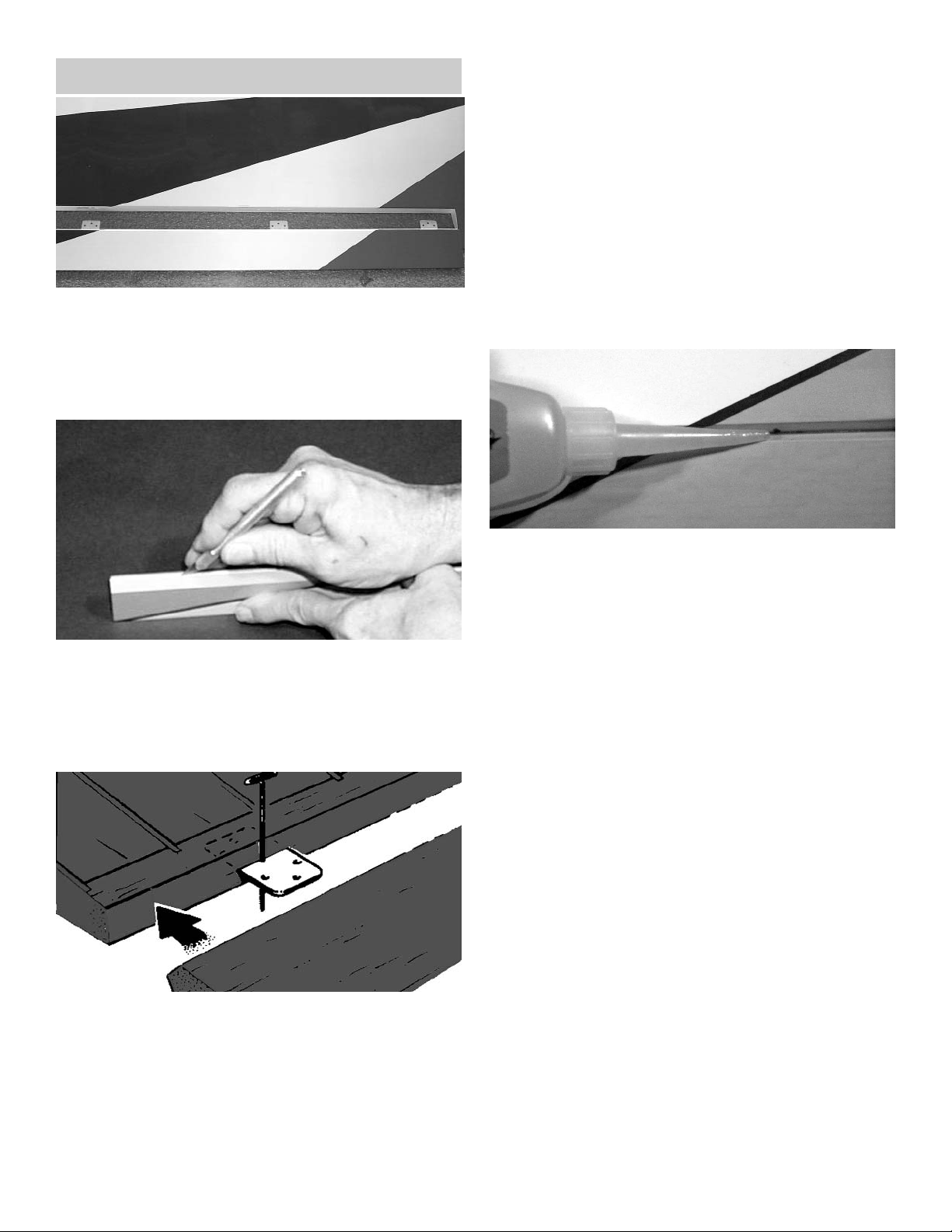
2. Locate the the servo hole in the bottom of
wing.
Carefully cut the covering over the servo
holes.
3. Tie the string to the wheel collar.
Insert the wheel collar with the string into the
servo hole.
While holding the wing up on the root rib, drop
the other end of the string with the nut into the
aileron servo hole. Allow the nut to fall down
through the wing rib holes till it rest against
the center root rib.
Pull the wheel collar with the string out the
hole in the bottom of the wing next to the center rib.
IMPORTANT! To ensure that any connections located inside the wing will not come loose, either when
the wires are pulled, or during flying, always tape
them securely together with electrical tape.
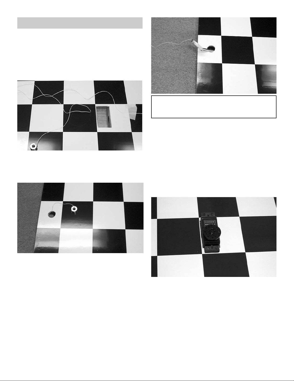
4. Attach the aileron servo wire to the12" exten-
sion and securely tape the connection together.
Tie one end of the string to the aileron servo
extension.
3.
SLOWLY pull on the string until the end of the
12" extension comes out of the hole.
Tape the extension securely to the wing, so
that it will not slide back in while you are working.
4. Using the screws supplied with your radio,
screw the servos to the mounting plates in the
wings.
Repeat these steps for the other aileron
servo.
Page 6
6
AILERON CONTROL HORN INSTALLATION
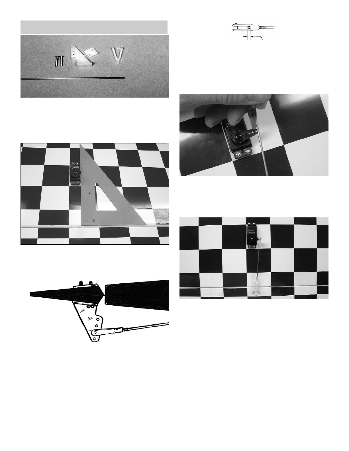
1. Collect the following items
(2) Large control horn with back plate
(4) 2-56 x 3/4" screw
(2) .072 x 10" threaded wire
(2) Snap link
(1) Nylon Swivel Keeper
2. With the aileron servo in place, make a mark
at a 90º degree angle to the trailing edge and
in line with the side of the servo.
3. Position the control horn so that the snap link
holes are on the mark just made and right next
to the hinge line, as shown.
4.
Using a 5/64" drill bit, make a pilot hole in
each screw location.
Mount the control horn with the 2-56 x 3/4"
screws.
5. Thread the .072 x 10” rod onto the snap link.
Make sure the rod shows in the center of the
snap link.
Place the snap link in the second hole from
the top on the control horn.
6. Making sure the aileron is in neutral (level)
position, mark where the wire meets the hole
on the servo arm.
Remove the wire and cut it about 1/2" beyond
the mark.
1/16"
Make a 90º bend (or a "z" bend, if preferred)
in the wire and insert the wire in the servo
arm.
Secure the wire with a nylon swivel keeper.
Repeat for the other servo in the other wing.
Page 7
7
WING STRUT BRACKET INSTALLATION
1. COLLECT THE FOLLOWING ITEMS:
(4) S
TRUT MOUNTING BRACKET
(4) #2 X 3/8 SHEET METAL SCREW
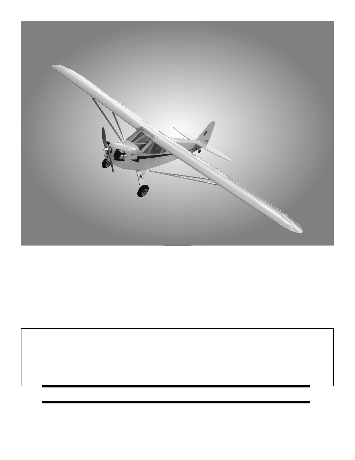
2. Place a small drop of thin CA glue into the
wing strut mounting holes found in the bottom
of the wing above and below the aileron
servo.
Slightly bend the strut mounting bracket in the
middle.
3. Using #2 x 3/8 sheet metal screw, mount the
bracket so that it is pointing to the fuselage.
2. Using epoxy, mount the 5/16 x 1-3/4” dowels
into the holes in the notch of the leading edge
of the wing. Make sure to leave about 1/2” of
dowel sticking out of the front of the wing. You
may wish to slightly taper the exposed dowel
ends for ease of insertion into the fuse holes.
1. Collect the following items:
(1) Right wing
(1) Left wing
(2) 5/16 x 1-1/2" dowel
(1) 3/4” x 17-1/2” aluminum tube
MOUNTING WING TO FUSELAGE
5. Insert the aluminum tube into one wing half
and push the tube into the wing until it stops.
Then insert the other wing half onto the tube
and slide the wing halves together.
Tilt the leading edge of the wing down into the
fuselage and insert both dowels in the holes
that are in the front of the fuselage
Insert a 1/4-20 x 2” nylon bolt into each hole in
the wing bolt pad and then insert each screw
into the holes near the trailing edge of the
wing.
Tighten both screws down until they are tight.
STAB INSTALLATION
1. Collect the following parts:
(1) Stabilizer
(1) Wing/fuse assembly
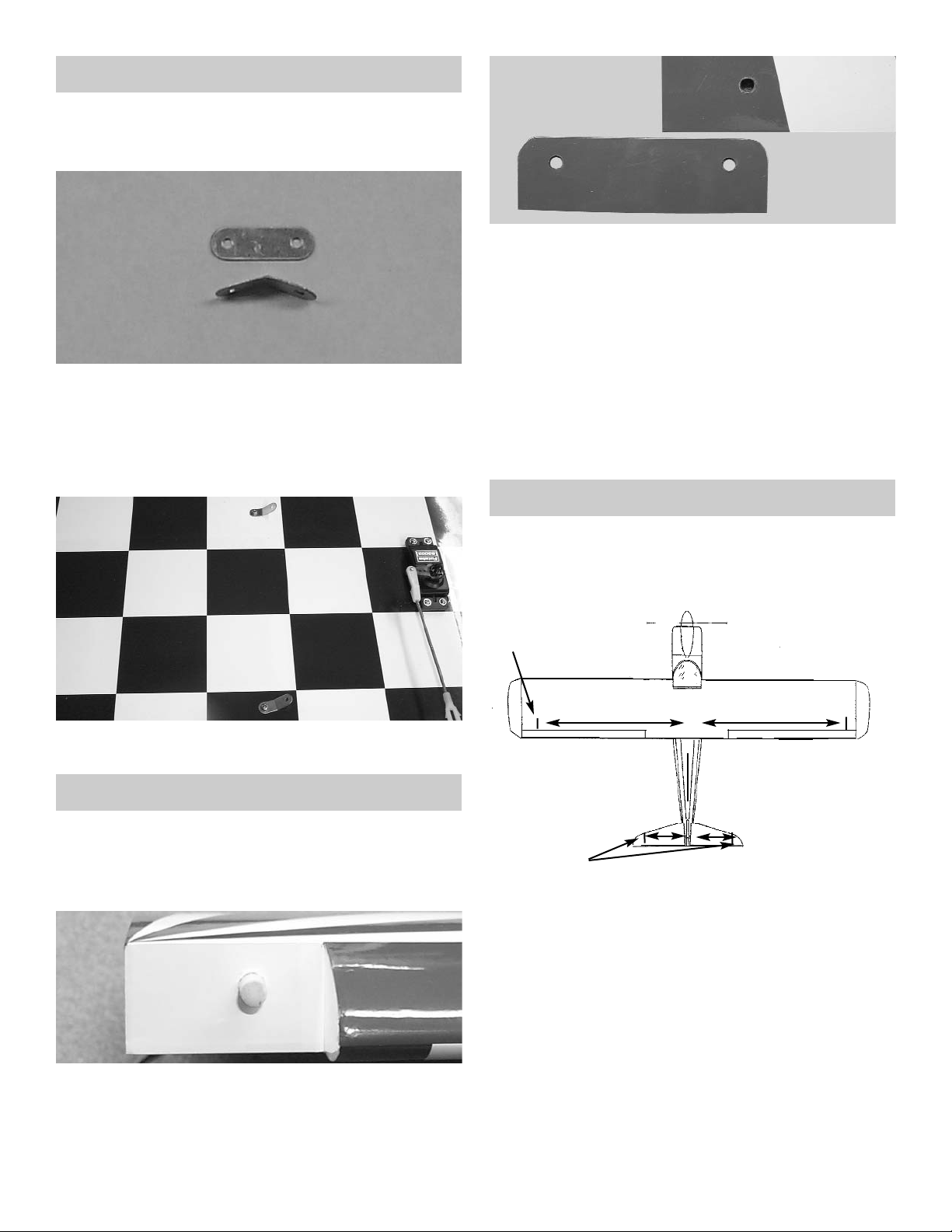
3. Place a piece of masking tape on each wing
tip, just above the aileron hinge line, as
shown above.
Measuring out from the center joint of the
wing,make a mark on the tape at 32-1/2".
Repeat for the other side of the wing
4.
Place two strips of masking tape along the
edge of the stab, next to the outer stab tips
and above the hinge line.
Measure the total length of the stab along the
hinge line and locate the centerline with a
mark.
Measure 9-1/2” out from the centerline and
make a mark on the masking tape on both
the left and the right side of the stabilizer.
32-1/2"
TAPE
TAPE
32-1/2"
9-1/2"
9-1/2"
Page 8
8
5. From the center point on the stab, draw a ver-
tical line up to the top of the stab.
Place masking tape on the top of the fuse, just
in front of the stab.
Measure and mark the center point on the
tape.
Mark a centerline on the fuselage, just behind
the wing.
Place a piece of masking tape along the top of
the fuselage, as shown, and draw a line from
the center mark in front of the stab up to the
center mark below the wing.
6. Place the stab on the platform with the center
of the stab lined up with the center point on
the fuse.
Measuring from the mark on each wing tip to
the mark on the stab tip, make sure the distance "X" on the right side is the same as the
distance on the left side.
TAPE
x
x
7. Check to see that the stab is level (parallel)
with the wing. If necessary, insert paper strip
shims to achieve proper alignment.
8. When satisfied with the alignment of the stab,
temporarily tape it securely in place.
Mark the area on the bottom of the stab where
it rests on the fuse.
Remove the stab from the fuse and, working
1/4" inside the drawn lines, carefully remove
the covering from the bottom of the stab. BE
CAREFUL TO AVOID CUTTING THE WOOD.
9.
Spread epoxy on both the bottom of the stab
and the stab platform of the fuse.
Replace the stab on the platform and, after
again checking the alignment of the stab to
the wing, allow the epoxy to dry thoroughly.
FIN INSTALLATION
1. Insert the elevator joiner in through the space
behind the stabilizer slot.
Page 9

9
2. Slide the fin mounting post into the rear of the
fuselage.
Check the fit. The fin should fit easily into the
slot at the rear of the fuselage and the notch
in the rear of the stab. The fin should stand
upright by itself. Enlarge the notch, if necessary.
TAKING CARE NOT TO CUT INTO THE
WOOD STRUCTURE UNDERNEATH, and
working inside the drawn lines, carefully
remove the covering where the fin mounts on
the fuse and stab.
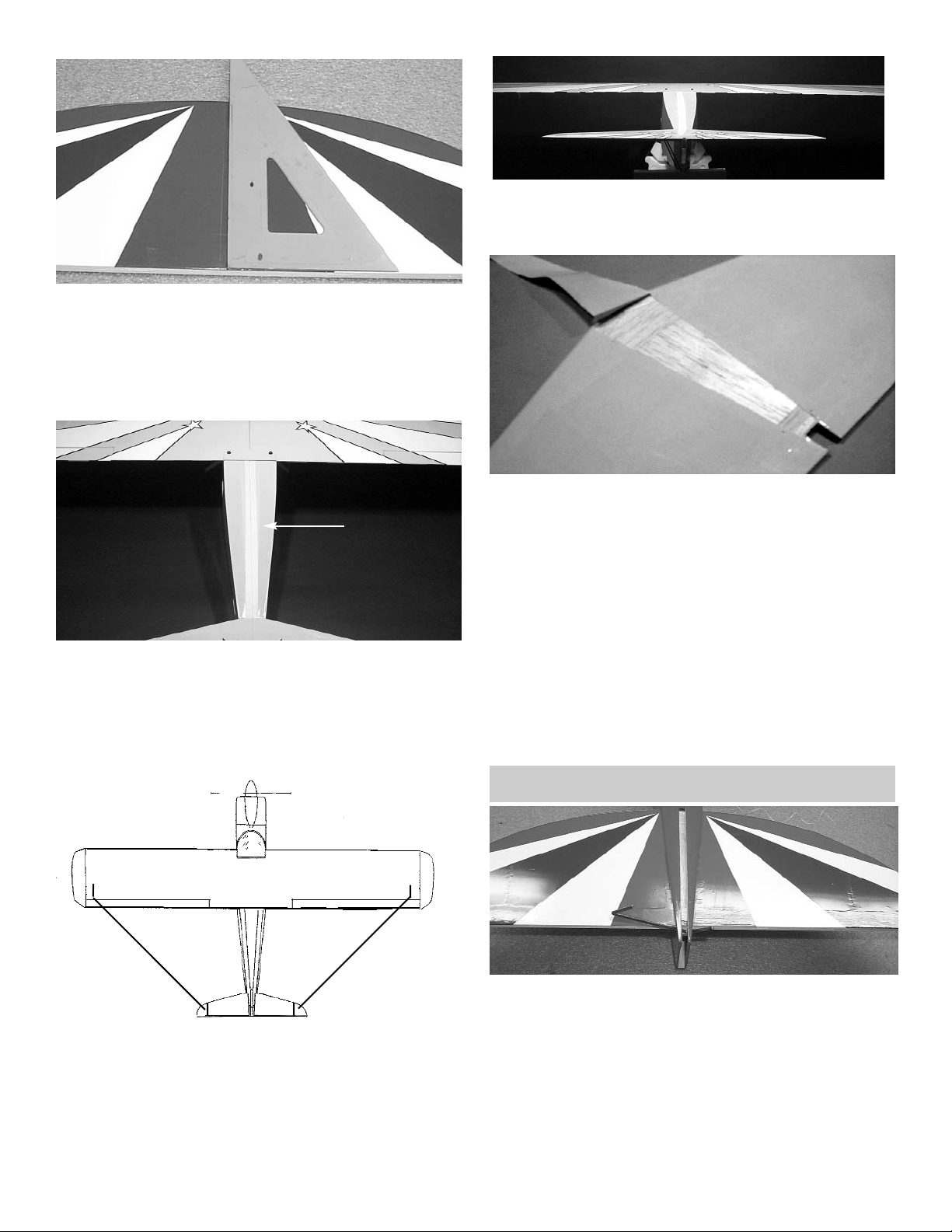
4. When satisfied with the fit, mark the location
of the fin on the fuse and stab by drawing a
line on both sides of the fin, as shown.
5. Remount the fin on the fuse and, using a 90º
triangle, make sure the fin is perpendicular to
the stab.
When satisfied with the fit, remove fin and mix
up a couple of spoonfuls of epoxy.
Apply a THIN, even coat of epoxy on the bot-
tom of the fin and along both sides of the fin
mounting posts. Avoid too much glue, which
will squeeze out from underneath the fin.
Mount the fin on the fuse and place the trian-
gle against the fin to make sure it is perpendicular.
Use masking tape to secure the fin and trian-
gle in position until the epoxy is thoroughly
dry. Make sure not to glue the triangle!
ELEVATOR HINGING
1. Collect the following items:
(1) Rudder
(2) Elevator
(6) Hinges
2. Take three hinges and, as with the aileron
hinge installation, insert the hinge into the elevator, using straight pins to ensure the hinge
stays centered between the stabilizer and the
elevator.
Inset the elevator joiner wire into the hole and
slot in the elevator, then slide the exposed
side of the hinges into the slots in the stab
until the pins touch both the stab and the elevator.
Page 10

10
3. Remove the pins in each hinge and, keeping
the elevator/stab assembly in position, apply 3
or 4 drops of thin CA to each hinge, on both
the top and bottom sides of the stab.
Allow ten minutes for the CA to cure before
flexing the elevator. Then install the second
elevator.
RUDDER HINGING
1. Collect the following items:
(1) Rudder
(1) Tail Wheel Bracket
(3) Hinges
1. Mark 1” up from the bottom of the rudder.
2. Drill a 3/32” hole on the hinge line at the 1”
mark you just made.
Cut a slot along the rudder hinge line for the
tailwheel wire to fit into.
Drill Hole
3. Mark where the tail wheel bracket meets the
fuselage.
4. Make a slot on the hinge line in the fin post for
the nylon tail wheel hinge bracket.
Place one drop of oil on the nylon hinge where
the wire goes through the hole.
Mix some epoxy for the nylon tail wheel hinge,
the glue the tail wheel hinge into the rudder
post.
Install the hinges into the rudder and glue the
rudder in place using the same hinging
method used for the elevator and
ailerons.Remember to leave a 1/32” gap at
the top of the rudder.
ELEVATOR PUSHROD
1. Collect the following items:
(1) Control horn
(2) 2-56 x 3/4" machine screw
(1) .072 x 27-1/4” Threaded Rod
(1) Nylon Clevis
(1) Silicone Clevis keeper
2. Insert one of the .072 x 27-1/4” threaded rods
into the elevator pushrod tube.
Page 11

11
3. Turn the fuselage over and pull the pushrod
out to the elevator.
Place the control horn so that it is at the end
of the pushrod and the clevis holes are over
the hinge line.
4. Mark the location of the mounting holes.
Using a 5/64" drill bit, drill the holes through
the elevator.
Using two 2-56 x 3/4" screws, screw the con-
trol horn and the backplate tightly to the elevator.
5. Place the silicone keeper over the pushrod.
Thread the nylon clevis onto the pushrod.
Snap the clevis onto the outer hole in the con-
trol horn.
Pull the silicon keeper onto the nylon clevis.
RUDDER PUSHROD
1. Collect the following items:
(1) Control horn
(2) 2-56 x 3/4" machine screw
(1) .072 x 27-1/4” Threaded Rod
(1) Nylon Clevis
(1) Silicone Clevis keeper
2. Insert the rudder pushrod just like you did the
elevator.
Place the control horn so that it is at the end
of the pushrod and the clevis holes are over
the hinge line.
Mark the location of the control horn mounting
holes. Try to mount the control horn over the
tailwheel wire so that the mounting screws are
on either side of the wine in the rudder.
ELEVATOR & RUDDER SERVO
1. Collect the following items:
(1) Fuselage
(2) Servo with hardware (Not Included)
(2) Swivel Keeper
2. Mount the elevator servo in as shown above.
Tape the elevator and the rudder so that they
are level with the stabilizer and the fin.
Page 12

12
3. Measure the length of the pushrod to the
servo arm hole and make a 90 degree bend.
Mount the swivel keeper on to the wire and
clip in place.
4. Repeat steps 2 & 3 for the rudder servo.
The servo should look the same as above
when finished.
INSTALLING THE ENGINE
1. Collect the following items:
(2) Motor Mounts
(1) Engine
(4) 8-32 x 3/4” Philip Head Screw
(4) 8-32 x 1” Philip Head Screw
(4) #8 Washer
(4) 8-32 Nylon Locking Nut
Note:
Your engine installation may be dif-
ferent then shown depending on the
motor you use.
Caution:
Always use thread lock on any type
of machine bolt and nut.
Note:
This installation is for a inverted
mounted engine. If you wish to have
a side mounted engine, then your
installation steps may be different.
You also might need
a round style motor mount and not
use the one beam mounts supplied in
this kit..
2. Using thread lock, mount the motor mounts to
the firewall using 8-32 x 3/4” screws with #8
washers.
Note:
The firewall is pre-drilled so that the
mounts have an opening of 1.67” this
will fit a O.S. 70 Surpass up to a O.S.
90 Surpass. The motor you choose
might require a different spacing. The
blind nuts can be removed and
changed if required.
Page 13

13
3. Place your motor on the motor mounts,
Center the motor between the mounts.
Measure from the firewall to the prop drive
washer 4-7/8 “.
Mark one of the engine mounting holes loca-
tion.
Using a 3/16 bit, drill on the mark.
Mount the motor to the motor mount using a 8-
32 x1” bolts and the #8 locking nut.
repeat for the other three motor mounting
holes.
1. Collect the following items:
(1) .072 x 15” threaded wire
(1) 1/8 x 9” nylon guide tubing
(1) Snap nut
(1) Pushrod connector
(1) 4-40 x 1/4” screw
NOTE: The following photos and instructions are for
mounting a 4-cycle engine. Other engines
might require different steps for installations.
THROTTLE PUSHROD INSTALLATION
2. Mark 1/4” from the end of the .072 wire and
make a 90º bend.
1/4”
3. Drill a 1/8” hole in the firewall in position with
the throttle arm.
Insert the 1/8” x 9” nylon tubing in the hole.
4. Let the tubing exit into the fuselage towards
the throttle servo mount.
Insert the throttle pushrod thru the tubing
starting at the firewall.
Insert the bent end into the throttle arm on the
carburetor.
PUSHROD CONNECTOR
SNAP NUT
5. Attach the Pushrod connector to a servo arm
same as shown above.
Page 14

14
6. Install the throttle servo into the servo tray.
Insert the pushrod wire through the connector
on the servo arm.
mount the servo arm onto the servo.
Note:
Do not cut the remaining pushrod wire till you
align the servo with the radio.
1. Gather the following items
(1) fuel tank
(1) rubber tank stopper
(1) clunk
(1) 3mm x 25mm screw
(1) cap washer large
(1) cap washer small
(1) 3mm x 40mm brass tube
(1) 3mm x 60mm brass tube
(1) silicone tube 4mm x 80mm
(2) silicone tube 5mm x 165mm
2. Insert the 3mm screw through the center hole
in the large washer, through the center hole in
the rubber washer against the large side, and
screw the small washer on the back side.
FUEL TANK ASSEMBLY
3. Insert the brass tubes through two of the
holes. They should be arranged so as the long
one will be on the right side of the plane and
the short one on the left side.
The tubes should extend out the front of the
cap 5/8”. Bend the long tube up at about a 20
degree angle. This should be adjusted so the
end of the tube almost touches the top of the
tank when installed.
4, Install the 4mm silicone tube to the short
brass tube and install the clunk to the other
end of the silicone tube. This is the fuel pickup and must be free to “flop” around in the
tank so it can pick up fuel in any attitude.
5. Install the assembly into the tank so the vent
tube is turned up to the top of the tank and is
positioned on the right side of the tank.
Tighten the screw to expand the rubber cap.
Don’t over tighten or you could split the tank.
Page 15

15
6. Attach the two pieces of 5mm tubing to the
two tank outlets. They are different colors so
you can tell which is the vent and which is the
fuel pickup after the tank is installed. Make a
note of which color you attach to which tube.
The short brass with the clunk is the fuel pickup and must go to the carburetor. The long
brass tube is the vent and should go to the
pressure outlet on the muffler.
Set tank aside till ready to install.
FUEL TANK INSTALLATION
1. Making sure the vent tube is pointing up inside
the tank, install the fuel tank through the fuselage cabin.
Insert the fuel lines through the hole in the fire-
wall
2. You can insert some optional foam rubber
under the fuel tank to help hold the tank in
place.
Connect the fuel lines to your motor.
MAIN LANDING GEAR
1. Collect the following items:
(4) 1/2” Brass Straps
(4) 2-56 Hex Nuts
(4) 2-56 x 5/16 Philip Head Screw
(2) Main Landing Gear Wire
(2) 1/2” Nylon Landing Gear Straps
(4) #2 x 5/16 Sheet Metal Screw
(4) #2 x 3/8 Sheet Metal Screw
(4) 5/32 Wheel Collars with Set Screws
(2) 3-1/4” Wheels
(2) Small Rubber Bands
(2) Covered Landing Gear Fairing
1. Bend the 1/2” brass straps the same as you
did on the wing.
Insert the 2-56 x 5/16 screws through the front
of the landing gear fairing.
Place a brass strap and a 2-56 hex nut and
tighten.(Don’t Forget to use Lock tight).
Repeat this for the other landing gear fairing.
Make sure you make a left and right side.
2. Insert the Main landing gear wire into the hole
in the bottom of the fuselage.
Hold the landing gear in place by using the
1/2” nylon straps across the wire and #2 x 3/8”
screws.
Page 16

16
3. Mount the fairing on the bottom of the plane
as shown above.
Drill a 1/16” hole for the brass straps and
screw them down with the #2 x 3/8 screws.
Place the small rubber band over the landing
gear wire and into the notch on the fairing.
Forward
4. Place one 5/32 wheel collar on the end of the
axle.
Insert the wheel onto the axle.
Place the second 5/32 wheel collar on the out
side of the wheel.
Center the wheel and the wheel collars on the
axle.
Tighten both the inside and the out side col-
lars.
Repeat for the other side of the landing gear.
TAIL WHEEL
1. Collect the following items:
(1) 1-1/2” Wheel
(1) 3/32 Wheel Collar with Set Screw
2. Slide the 1-1/4” wheel onto the tail wheel
bracket.
Place a 3/32” wheel collar on the axle and
tighten the set screw.
COWL INSTALLATION
1. Collect the following items:
(1) Cowl
(1) Fuselage
(4) #2 x 3/8 Sheet Metal Screw
Note:
Your cowl installation may be differ-
ent then shown depending on the
motor used.
2. Very carefully start removing the side of the
cowl where the engine will protrude.
Make sure that you leave space around the
engine so that the cowl will not rub on the
engine.
Page 17

17
3. Keep the hole in the front of the cowl centered
on the engine.
4. Screw the cowl to the fuselage using #2 x 5/16
screws.
WINDOWS
1. Collect the following items:
(1) Fuselage
(1) Windshield
(1) Side windows (Right & Left)
2. Using scissors, cut around the outside of the
windows leaving a 1/8” flange around the
edge.
3. Keep the two rear windows together but, cut
the front window off by cutting down the middle of the space between the 1st and 2nd window.
4. Glue the windows in using a small amount of
medium CA glue or a canopy glue, on the
flange around the outside of the window.
Holding or tape the window in place till the
glue hardens.
Page 18

18
Cut along
this line
5. Temporary tape the front Windshield in place
on the fuselage.
Mark the side of the Windshield using a pen or
pencil where shown above.
Remove the Windshield and cut along the line
that you just drew.
Cut the top of the windshield even with the
back of the wing mount former.
6. Temporary place the Windshield back on the
fuselage and mount the wing.
Make sure the Windshield does not interfere
with the wing mounting to the fuselage.
7. Remove the wing and glue the Windshield to
the fuselage.
Use masking tape to hold the windshield in
place till dry.
WING STRUTS
1. Collect the following items:
(1) Fuselage
(2) Wing Struts
(6) 2-56 Silver Clevis
(6) 2-56 Hex Nut
(6) Clevis Clips
(2) Aluminum Strut Bracket
(2) #2 x 5/16 Screw
2. Place the aluminum strut brackets just behind
the landing gear fairings.
Make a mark where the mounting holes are
located.
Drill 1/16” holes at the marks and mount the
straps using the #2 x 5/16” screws.
3. On each end of the wing struts place a 2-56
hex nut, and a 2-56 Golden clevis.
4. Hook the bottom of the strut to the aluminum
bracket on the bottom of the fuselage.
Page 19

19
5. Attach the wing to the strut by screwing the
clevises in & out to the straps.
Caution:
Tighten the wing struts just enough
so that you do not have to “pull or
tug” to put the struts on or off the
wing and fuselage brackets.
Do not over tighten the struts they
can distort the wing.
RECEIVER, BATTERY & SWITCH
3. Drill a hole in the bottom of the fuselage and
extend the receiver out to the tail.
Wrap the battery in foam and place it under or
just behind the fuel tank. After checking the
CG you can move the battery around to get
the right balance.
1. Install your radio switch.
2. Plug in your receiver. Make sure you wrap the
receiver in foam.
OPTIONAL FLYING WIRES
WE RECOMMEND THAT YOU USE FLYING
WIRES IF YOU WILL BE USING ANY ENGINE
LARGER THAN A .70 2 STROKE OR .91 4
STROKE
1. Locate the following parts
Roll of braided cable
(8) metal brackets (2 with one larger
holes)
(4) 2-56 rigging couplers
(4) golden clevis
(4) metal clevis retainers
(8) cable swages
(3) 2-56 x 1/2” screws
(3) 2-56 nuts
(3) #2 flat washers
(2) #2 x 1/2” sheet metal screws
Page 20

20
2. Take the 8 flat brackets and bend in the
middle to about a 30 degree angle.
Use the three 2-56 x 1/2” screws with a wash-
er under the head, and mount the brackets to
the fin and stab with the aircraft nut on the bottom.
Caution:
Use thread lock on all bolts and nuts.
3. The brackets go on each side of the fin and
stab with one bolt holding two on. There is a
predrilled hole at each location. Hold up to a
light to help locate the hole under the covering.
4. Measure forward 1” from the rudder hinge
line.
Mount the other two brackets with the one
larger hole to the bottom of the fuselage using
the #2x1/2” sheet metal screws.
6. Loop the end of the cable back though the
brass tube.
Use pliers and crimp the brass tubing onto the
cable to secure it.
5. Insert the cable through the 1/16 OD x 1/4”
brass tubing.
Next thread the cable though the hole at the
end of the 2-56 threaded rods and pass it
back through the brass tube.
7. Screw a golden clevis on the rigging coupler.
and attach it to the bracket at the fin.
Pull the cable to the bracket on the stab and
cut 2” past the hole.
8. Pass the cable through the brass tube,
through the bracket on the stab and back
through the brass tube.
Pull the cable tight, but be careful not to put
pressure on the stab or fin. we want the cable
to just be snug at this point and we will adjust
the tension after all four are in place.
Loop the cable back through the brass tube
again and crimp.
Use pliers and crimp the brass tubing onto the
cable to secure it.
Page 21

21
The wires should just be snug with no slop,
don’t distort the flying surfaces with
too much tension.
8. Pass the cable through the brass tube,
through the bracket on the stab and back
through the brass tube. Pull the cable tight,
but be careful not to put pressure on the stab
or fin. we want the cable to just be snug at this
point and we will adjust the tension after all
four are in place. Loop the cable back through
the brass tube again and crimp.
Repeat for the other four cables.
6.
After all four flying wires are in place, adjust
the tension by disconnecting the clevis and
turning.
The Following is from the Carl
Goldberg Products Anniversary Cub
Booklet
1. Using glass cleaner and a soft cloth, clean the
model surface thoroughly before applying
decals.
2.
Cut the decal sheets apart in sections, as
needed.
Fold the decal in half, front to rear. Open at
the fold and place the decal on a flat surface.
The protective backing will bubble away from
the decal at the fold.
DECAL APPLICATION
We have given you small “N” numbers to be
place on the rudder or you can use the larger “N”
numbers on the side of the fuselage if you choose.
If you choose to place the numbers on the
side you will have to remove the black stripe where
the number will rest. Remove the stripe by using a
iron set to 300 deg. and gently pulling the stripe up.
Once you have applied the number then you can
reapply the stripe using heat.
Page 22

22
Throws
Use these control throws for the first
flights. Work your way up to more throw
movement when you are comfortable
with the Cub ARF.
Elevator 3/4” UP & Down
Ailerons 3/8” Up & Down
Rudder 1” Right & Left
When you have gotten comfortable
flying the Cub slowly increase the throws
while still staying within your flying ability.
The Cub was designed around a
.70 to .91 four-cycle engine these
engines will give you excellent performance. Remember, a bigger engine is not
always better.
BALANCING AND CONTROL THROWS
CG Balancing
Balancing the Cub is very important, you
might need to use weight depending on
the servos and engine that you use. Start
out with the balance point between 3-3/4
to 4-1/4. This range of balance point is a
safe place for you to fly the Cub. As you
get comfortable you can move the CG
back further. The further you move the
CG the more wild the aerobatics will
become, BUT the more unstable the Cub
will also become.
Page 23

23
Page 24

24
 Loading...