

Page 1
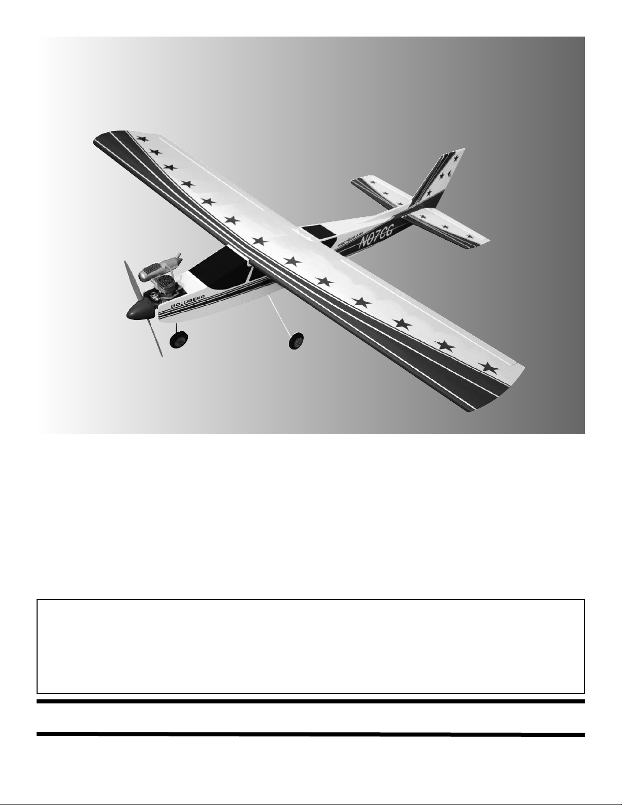
Protégé 60
Protégé 60
ARF
ARF
WARNING
A radio-controlled model is not a toy and is not intended for persons under 16 years old. Keep
this kit out of the reach of younger children, as it contains parts that could be dangerous. A radiocontrolled model is capable of causing serious bodily injury and property damage. It is the buyer's
responsibility to assemble this aircraft correctly and to properly install the motor, radio, and all other
equipment. Test and fly the finished model only in the presence and with the assistance of another
experienced R/C flyer. The model must always be operated and flown using great care and common
sense, as well as in accordance with the Safety Code of the Academy of Model Aeronautics (5151
Memorial Drive, Muncie, IN 47302, 1-800-435-9262). We suggest you join the AMA and become properly insured prior to flying this model. Also, consult with the AMA or your local hobby dealer to find an
experienced instructor in your area. Per the Federal Communications Commission, you are required
to use only those radio frequencies specified "for Model Aircraft."
LIMITED WARRANTY
Carl Goldberg Products, Ltd. has inspected and certified the components of this aircraft. The company urges the buyer to perform
his own inspection, prior to assembly, and to immediately request a replacement of any parts he believes to be defective for their
intended use. The company warrants replacement of any such components, provided the buyer requests such replacement within a period of 90 days from the date of purchase and provided the defective part is returned, if so requested by the company.
No other warranty, expressed or implied, is made by the company with respect to this kit. The buyer acknowledges and understands that it is his responsibility to carefully assemble the finished flying model airplane and to fly it safely. The buyer hereby
assumes full responsibility for the risk and all liability for personal or property damage or injury arising out of the buyer's use of the
components of this kit.
CARL GOLDBERG PRODUCTS, LTD.
P.O. Box 818 Oakwood GA 30566 Phone #678-450-0085 Fax # 770-532-2163 www.carlgoldbergproducts.com
©copyright 2006
Page 2

2
Congratulations on your purchase of the
Protégé 60 ARF. Every effort has been made
to produce a lightweight, straight, easy to
assemble aircraft. Quality hardware components have been provided, It is your responsibility as an pilot to fly the aircraft in an intelligent
manner. Carl Goldberg Products has flown the
Protégé 60 ARF through a very rigorous flighttesting schedule and have stressed the airframe
beyond all practical parameters without a single
failure. Carl Goldberg Products will NOT
warrant the Protégé 60 ARF against flutter due to
improper set-up or excessive speed maneuvers.
having said that, we believe you will find the
Protégé 60 ARF to be one of the best trainers
on the market .
We are very proud of the construction of the
Protégé 60 ARF and all of our other ARF aircraft. Each aircraft is jig built to insure a straight
true airframe. Every effort is made to build as
light an aircraft as possible. As with any professional builder, glue is used sparingly. Please
take a moment during assembly and run a
bead of Ultra Set™ CA or aliphatic resin into
the high stress joints that you can reach
such as the landing gear plate, servo mounting trays, wing hold down blocks, etc. Also,
during the course of shipping from the manufacturer to our facility in the United States, it is not
uncommon for the aircraft to experience several
changes in climate. This may cause the iron-on
covering to develop wrinkles. This is not a fault
of the manufacturer. Please take a few minutes
with your heating iron and heat gun to iron
down the seams and re-shrink the covering
where needed. The results will be a beautiful
aircraft with a breathtaking finish that you will
be proud to display at your flying club.
Before beginning assembly of your Protégé 60
ARF, we highly recommend that you study this
manual in its entirety. You should begin planning
your radio installation based on your choice of
engine and equipment from the beginning.
Building supplies needed
Hobby knife w/#11 blades
Thin Ultra Set™ CA
Medium Ultra Set™ CA
Canopy glue
30 minute Ultra Set™ epoxy
Thread lock
Diagonal wire cutters
Pliers
Assorted drill bits
Various sized screwdrivers( both Phillips and
standard head)
Tape measure
Dry-erase marker
Paper towels
Rubbing alcohol
Electrical tape
4-40 Tap & Die Set
3/32, 7/64, 9/64 & 3mm Allen wrench
Wax Paper
Note:
Thread lock must be used where
ever any machine bolts are going into
any type of nuts. If you do not use
thread lock the bolts could become
loose and fall out in flight.
Page 3

3
ADHESIVES & GLUING TECHNIQUES
Ultra Set™ CAadhesives are specially formulated to firm-
ly glue the plywood, hardwood, and balsa used in your
model and to withstand the vibration and stresses of high
performance flight. However, there are times, such as
when you are installing the stabilizer and fin on the fuselage and want more set-up time for careful alignment and
positioning, then you should use Ultra Set™ epoxy .
Occasionally, you also will want to use thin CA, which
"wicks" into the surrounding areas. Aliphatic resin glue or
similar water-based glues can also be used, but they will
add to the assembly time because they dry so much more
slowly than Ultra Set™ CAglue. Remember, when ever
using any CA, you must be careful to read instructions thoroughly, as you will have only seconds for positioning of
parts. Be sure to trial fit parts together before gluing. Also,
never use watery THIN type CA glue for gluing plywood
and hardwood parts. Thin CA's do not adequately bond
these areas.
CAUTION
Some people may experience an allergic reaction when
exposed to fumes from CA glue or epoxy . As with paints,
thinners, and solvents, it is always important to use glues
only where there is adequate ventilation to carry fumes
away. A fan is recommended. Also, special care must be
taken when using CA, as it will bond skin as well as other
surfaces. Before using any CA, carefully read all label precautions. When using CA, protective eye-wear and care in
keeping the glue away from the face is highly recommended. If CA does happen to get into the eye, hold lid open
and flush with water only. Seek immediate medical attention.
PREPARING FOR ASSEMBLY
You will need a work area of approximately 24 x 48" which has
been covered to protect it from adhesive, as well as cuts and
other damage. Many people cover their work area with a
sheet of dry wall (sheet rock) and/or waxed paper t o prevent Ultra Set™ CA Glue and Ultra Set™ epoxy from ruining
the work surface.
CONSTRUCTION TIPS
IMPORTANT: ALWAYS READ A FEW STEPS AHEAD.
This will alert you to coming instructions and will help you
plan accordingly.
Using the Parts Identification section, familiarize yourself
with the various items included in your kit box.
COVERING
The Protégé 60 ARF is covered in a premium polyester film chosen by many of the world's top flyers for its
beauty, toughness, and ease of application and repair. It
is not uncommon for ARF's to develop a few wrinkles in
transit. If this is true of your model, the situation is easily
corrected. Before you begin putting the pieces together,
run around the edge of the seams first then over the surface of each section with an iron (either specially
designed for airplane use or the more cumbersome
household iron). Apply the heat (set at about 350° F), following along with a soft cloth and pressing down on the
covering as you go around. This will more firmly set the
covering adhesive into the wood and keep your aircraft
covering tight and smooth in the future. Once you have
ironed the seams stay away from them with the heat or
the covering will slide when you try to shrink the middle.
If this happens the wrinkles will not come out of the covering.
ITEMS NEEDED TO COMPLETE THIS AIRCRAFT
1 RADIO GUIDANCE SYSTEM (4 CHANNEL
MINIMUM REQUIRED WITH 5 SERVOS,
54OZ TORQUE MINIMUM)
2 12” SERVO EXTENSION WIRES
1 Y-HARNESS
1 Ultra Set™ CA ACCELERATOR
1 2 OZ. BOTTLE Ultra Set™ CA MEDIUM
GLUE
1 1/2 OZ. BOTTLE Ultra Set™ CA THIN
GLUE
1 30 MINUET Ultra Set™ EPOXY
1 1/2” FOAM RUBBER
1 2-3/4” SPINNER
NOTE: The
Protégé 60 ARF covering closely
matches Oracover:
(#866) True Red,
(#873) Deep Blue
(#870) White
Page 4

AILERON SERVO INSTALLATION
1. Collect the following parts:
(1) Left wing
(1) Right wing
(2) Servos
(2) 12” Servo Extension
(1) Servo “Y” Harness
2. Attach the 12” servo extension to the servo.
IMPORTANT! To ensure that any connections locat-
ed inside the wing will not come loose, either when
the wires are pulled, or during flying, always tape
them securely together with electrical tape.
3. Starting from the servo hole, insert the servo
extension and the servo wire into the servo
hole.
Allow the wire to fall straight down through
though the wing till it exits the the hole in the
bottom of the wing at the center
Tape the extension wire to he bottom of the
wing.
Repeat for the other wing half..
1. Collect the following items:
(2) nylon swing in keepers
(2) 2-56 pushrods threaded one end
(2) 2-56 clevis
(2) silicone clevis retainers
2. Slide the silicone keeper on the clevis
Screw the 2-56 pushrod into the nylon clevis
so 1/16” of threads extend past the opening
Attach the clevis to the top hole on the aileron
control horn..
3. Center the aileron servo and make sure the
aileron is aligned with the wing at the root end.
Insert the end of the pushrod into the servo
arm.
Install the nylon swing in keeper to attach the
pushrod.
Repeat for the other aileron.
AILERON SERVOS PUSHRODS
4. Install the servo into the servo hole and screw
in place using the screws supplied with your
radio.
IMPORTANT! Check to confirm all control horns are
securely tightened to all control surfaces.
Page 5

5
TAIL INSTALLATION
1. Collect the following items:
(1) Fuselage
(1) Stabilizer
(1) Fin
(2) 4-40 nylon locking nuts
(4) 4-40 x 3/4 “ socket head screws
(6) #4 washers
Thread lock
Note:
Thread lock must be used where ever any
machine bolts are going into any type of nuts. If
you do not use thread lock the bolts could
become loose and fall out in flight.
We recomend that you epoxy the fin and
the stabilizer together onto the fuselage if you
will not be removing them.
1. Look for the holes in the center of the stabiliz-
er.
Insert the studs that are protruding out the
bottom of the fin into the top of the stabilizer.
(Stars side is up)
Place a #4 washer and a nylon locking nut on
each threaded stud.
Tighten both locking nuts.
2. Place the stabilizer fin assembly onto the rear
of the fuselage.
Make sure to use thread lock on these bolts.
Insert (4) 4-40 x 3/4” bolts with washers
through the top of the stabilizer and into the
blind nuts mounted on the fuselage
Tighten all 4 bolts.
Remove this cardboard protector
3. connect the snap link to the elevator and rud-
der control horns.
Slide the silicone keeper over the snap link.
MAIN GEAR & WHEEL INSTALLATION
1. Collect the following items:
(2) Landing gear wire
(4) 2 x 5/16"screw
(2 Landing gear strap
(3) 2-1/2" wheel
(4) Wheel collar
(4) Set screw
2. Insert one gear leg in the hole in the bottom
of the fuselage.
Page 6

6
3. Insert the other gear leg in the hole on the
other side of the fuselage. One hole is at the
back of the slot and the other is at the front
of the slot. The two wires will lie next to each
other in the slot.
Use the two straps and four screws to retain
the gear.
4. Install the wheels on the axles, as shown.
First the wheel collar goes on, followed by
the wheel, then the second wheel collar, and
the set screw. Tighten the set screw.
AXLE
WHEEL
SET SCREW
WHEEL COLLAR
WHEEL COLLAR
NOSE GEAR INSTALLATION
(1) Nose gear strut
(2) Wheel Collars and set screws
(1) Wheel
(1) Nose gear steering arm
(1) 1.5mm x 43 cm wire and tube
(1) EZ connector and screw
(1) Nylon Swivel Keeper
2. place the nose gear pushrod wire onto the
nylon steering arm.
3. Slide the nose gear gear strut into the bear-
ing and through the steering arm.
Adjust the nose gear till the coil is just off the
fuselage bottom.
Tighten the set screw against the nose gear
in the steering arm.
Page 7

7
Caution:
Thread lock must be used where
ever any machine bolts are going into
any type of nuts. If you do not use
thread lock the bolts could become
loose and fall out in flight.
Place thread lock on each of the
bolts holding the motor mount to the
firewall. Make sure each bolt is tight
to the fire wall.
Note:
The Protégé 60 ARF was designed for any .60 size 2 stroke motor. We have set
the motor mounts to fit most .60’s. We are showing an OS.61 FX 2 stroke. If
your motor will not fit in the mounts then you will have to remove the motor
mounts and move them to fit you motor.
ENGINE INSTALLATION
1. The motor mounts are pre installed for an OS
61 FX.
Install you engine using the socket head
sheet metal screws.
2.
Place the throttle push rod snap link on the
carburetor.
Slide the silicone keeper over the snap link.
3. Install the fuel lines to the engine.
Carburetor Fuel Line
Vent Line
Page 8

8
RADIO INSTALLATION
Engine
1. Install the servos as shown above.
Adjust the pushrods so that the servo arms
are centered.
2. Remove the screw that holds the fuel tank
brace and remove the brace.
Wrap your radio battery with 1/2” foam (not
included) and place it on the fuselage bottom
just behind the fuel tank.
Wrap your receiver in 1/2” foam (not includ-
ed) and place it in front of the servo tray.
Engine
Screw for fuel
tank brace
Screw for fuel
tank brace
3. Reinstall the fuel tank brace.
3. Find the switch hole precut in the side of the
fuselage and install the radio switch..
Engine
1. Using glass cleaner and a soft cloth, clean the
model surface thoroughly before applying
decals.
Cut the decal sheets apart in sections, as
needed.
Peel the backing off the decal and apply the
decal to the plane.
DECAL
Page 9

9
Throws
Use these control throws for the first
flights. Work your way up to more throw
movement when you are comfortable
with the Protégé 60 ARF.
Elevator 7/16” High / 1/4” Low
Ailerons 7/16” High / 1/4” Low
Rudder 1/2” Right & Left
When you have gotten comfortable flying
the Protégé 60 ARF slowly increase the
throws while still staying within your flying
ability.
BALANCING AND CONTROL THROWS
CG Balancing
Balancing the Protégé 60 ARF is very
important, you might need to use weight
depending on the servos and engine that
you use. Start out with the balance point
at 4” to 4-3/4”. Measure next to the fuselage back from the leading edge.
Balance the Protégé 60 ARF right side
up.
 Loading...