

Page 1
INSTRUCTIONS
Welcome to the world of Ultimate flying! Now that you're an experienced R/C pilot, you're ready to step up to
a higher level of aerobatic flying. And we've made sure this ARF version won't disappoint. With just the same
flight characteristics as the kitted version, you'll soon know why the Carl Goldberg Products Ultimate has
been America's favorite sport biplane since 1990.
WARNING
A radio-controlled model is not a toy and is not intended for persons under 16 years old. Keep
this kit out of the reach of younger children, as it contains parts that could be dangerous. A radiocontrolled model is capable of causing serious bodily injury and property damage. It is the buyer's
responsibility to assemble this aircraft correctly and to properly install the motor, radio, and all other
equipment. Test and fly the finished model only in the presence and with the assistance of another
experienced R/C flyer. The model must always be operated and flown using great care and common
sense, as well as in accordance with the Safety Code of the Academy of Model Aeronautics
(www.modelaircraft.org). We suggest you join the AMA and become properly insured prior to flying this
model. Also, consult with the AMA or your local hobby dealer to find an experienced instructor in your
area. Per the Federal Communications Commission, you are required to use only those radio frequencies specified "for Model Aircraft."
LIMITED WARRANTY
Carl Goldberg Products, Ltd. has inspected and certified the components of this aircraft. The company urges the buyer to perform his own inspection, prior to assembly, and to immediately request a replacement of any parts he believes to be defective for
their intended use. The company warrants replacement of any such components, provided the buyer requests such replacement
within a period of 90 days from the date of purchase and provided the defective part is returned, if so requested by the company.
No other warranty, expressed or implied, is made by the company with respect to this kit. The buyer acknowledges and understands that it is his responsibility to carefully assemble the finished flying model airplane and to fly it safely. The buyer hereby
assumes full responsibility for the risk and all liability for personal or property damage or injury arising out of the buyer's use of
the components of this kit.
1
PT. #2045 6/03
The Ultimate ARF
CARL GOLDBERG PRODUCTS, LTD.
P.O. Box 818 Oakwood GA 30566 Phone #678-450-0085 Fax # 770-532-2163 www.carlgoldbergproducts.com
© Copyright 2000 Carl Goldberg Products LTD.
Page 2

ITEMS NEEDED TO COMPLETE THIS AIRCRAFT
1 RADIO GUIDANCE SYSTEM (4 CHANNEL
MINIMUM REQUIRED)
2 12” AILERON SERVO EXTENSION WIRES
1 Y-HARNESS
1 ENGINE .60-.90 2-CYCLE, .90-1.20 4-
CYCLE AND MUFFLER
1 2 OZ. BOTTLE CA GLUE
1 1/2 OZ. BOTTLE CA GLUE
1 EPOXY
1 8 x 12 FOAM RUBBER
OPTIONAL:
1 PILOT FIGURE
1 SWITCH HARNESS
*
NOTE: The Ultimate ARF covering matiches
Bright Yellow(#872), Deep Blue(#873)
UltraCote®.
UltraCote® is a registered trademark of Horizon Hobby Distributors
TOOLS AND SUPPLIES FOR ASSEMBLY.
MODELING OR UTILITY KNIFE
WORK SURFACE (24" X70")
ELECTRIC DRILL
1/16”, 3/32”,1/8", 3/16”, 5/32”, 1/4”, 5/64”
7/32” DRILL BITS
SMALL STANDARD & PHILLIPS SCREW-
DRIVERS
MASKING TAPE
NEEDLE NOSE PLIERS
MOTO TOOL
24” RULER
FLEXIBLE STRAIGHT-EDGE
30-60-90° x 6" TRIANGLE
SOFT PENCIL
A FEW STRAIGHT OR "T" PINS
ADJUSTABLE WRENCH
WIRE CUTTER (DYKES)
OPTIONAL HEAT GUN/COVERING IRON
ACID BRUSH
ELECTRICAL TAPE
SOLDERING IRON, FLUX, SOLDER
PIECE OF MEDIUM SANDPAPER
5 FT. LENGTH OF STRING
2
Page 3

INTRODUCTION
USING THIS INSTRUCTION MANUAL
Before you begin assembling your ULTIMATE ARF, take
some time to read through this entire instruction book. It
is designed to take you step-by-step through the process
and to give you added information on engine and radio
selection and set-up, balancing your aircraft, and flying
your model. The time you spend will speed the assembly process and help you avoid problems.
PREPARING FOR ASSEMBLY
You will need a work area of approximately 24 x 70" which has
been covered to protect it from adhesive, as well as c uts and
other damage. Many people cover their work area with a
sheet of dry wall (sheet rock) and/or waxed paper t o
prevent CAglue and Epoxy from ruining the work surface.
CONSTRUCTION TIPS
IMPORTANT: ALWAYS READ A FEW STEPS AHEAD.
This will alert you to coming instructions and will help you
plan accordingly.
Using the Parts Identification section, familiarize yourself
with the various items included in your kit box.
As you work, CHECK OFF EACH STEP in the box provided, so that you are sure you do not forget anything.
Do not hesitate to ask questions. Your local hobby dealer and area flyers will most likely by happy to help, as
they want you to have a successful flying experience.
You may also receive technical assistance from Carl
Goldberg Models via e-mail (questions@carlgoldbergproducts.com) or by telephone 1-678-532-0085.
tCAUTION
Some people may experience an allergic reaction when
exposed to fumes from CA glue or epoxy. As with paints,
thinners, and solvents, it is always important to use glues
only where there is adequate ventilation to carry fumes
away. A fan is recommended. Also, special care must be
taken when using CA, as it will bond skin as well as other
surfaces. Before using any CA, carefully read all label precautions. When using CA, protective eye-wear and care in
keeping the glue away from the face is highly recommended. If CA does happen to get into the eye, hold lid
open and flush with water only. Seek immediate medical
attention.
COVERING
The Ultimate ARF is covered in genuine a premium polyester film chosen by many of the world's top flyers for its
beauty, toughness, and ease of application and repair. It
is not uncommon for ARF's to develop a few wrinkles in
transit. If this is true of your model, the situation is easily corrected. Before you begin putting the pieces together, run over the surface of each section with an iron
(either specially designed for airplane use or the more
cumbersome household iron) or use a modeling heat
gun. Apply the heat (set at about 350° F), following
along with a soft cloth and pressing down on the covering as you go around. This will more firmly set the covering adhesive into the wood and keep your aircraft covering tight and smooth in the future.
3
Page 4
1. Collect the following parts:
(1) Top Wing
(1) Bottom Wing
(4) Ailerons
(16) Jet Hinges
WING CONSTRUCTION
Aileron Installation
2. Locate the pre-cut aileron hinge slots in both
the top and the bottom wings. Using a hobby
knife (#11 blade), slide the blade into each of
the slots to make sure they are cleanly cut.
Repeat this process with the ailerons, mak-
ing sure all hinge slots are clean.
3.
Place a straight pin into the center of each of
four Jet Hinges.
3.
Slide four hinges into the hinge slots on one
side of a wing The straight pin will prevent
the hinges from going further than halfway
into the wing.
4.
Select one of the ailerons and insert the
exposed half of each hinge into the aileron
slots. Slide the aileron toward the wing until
no gap remains between the aileron and the
wing.
When satisfied with the alignment, remove
the straight pins, being sure to keep the
aileron tight to the wing. You may wish to
apply a few pieces of masking tape to keep
the pieces in place.
6.
Keeping the aileron and wing in position,
apply 3 or 4 drops of Instant thin CA to the
small exposed area of each hinge.
Turn the wing assembly over and again
apply 3 or 4 drops of thin CA to the exposed
hing surface.
Allow to dry for 10 minutes before flexing the
aileron.
7.
Repeat the above steps for each of the other
ailerons.
NOTE: Remember that the following pictures may
not exactly match the hardware you are using.
Always check the manufacturer’s instructions when
installing radio equipment.
5. Carefully check the alignment of the aileron,
making sure it is flush with the end of the
wing.
1. Collect the following parts:
(1) Aileron servo door
(2) 3/8 x 3/4 x 3/4"servo mounting block
(4) 1/8 x 3/4 x 3/4 aileron door mounting plate
(4) Servo mounting screw (supplied with radio)
(4) #2 Washer
(4) #2 x 3/8" screw
(1) Servo with rubber grommet
Aileron Servo Installation (Bottom Wing)
4
Page 5
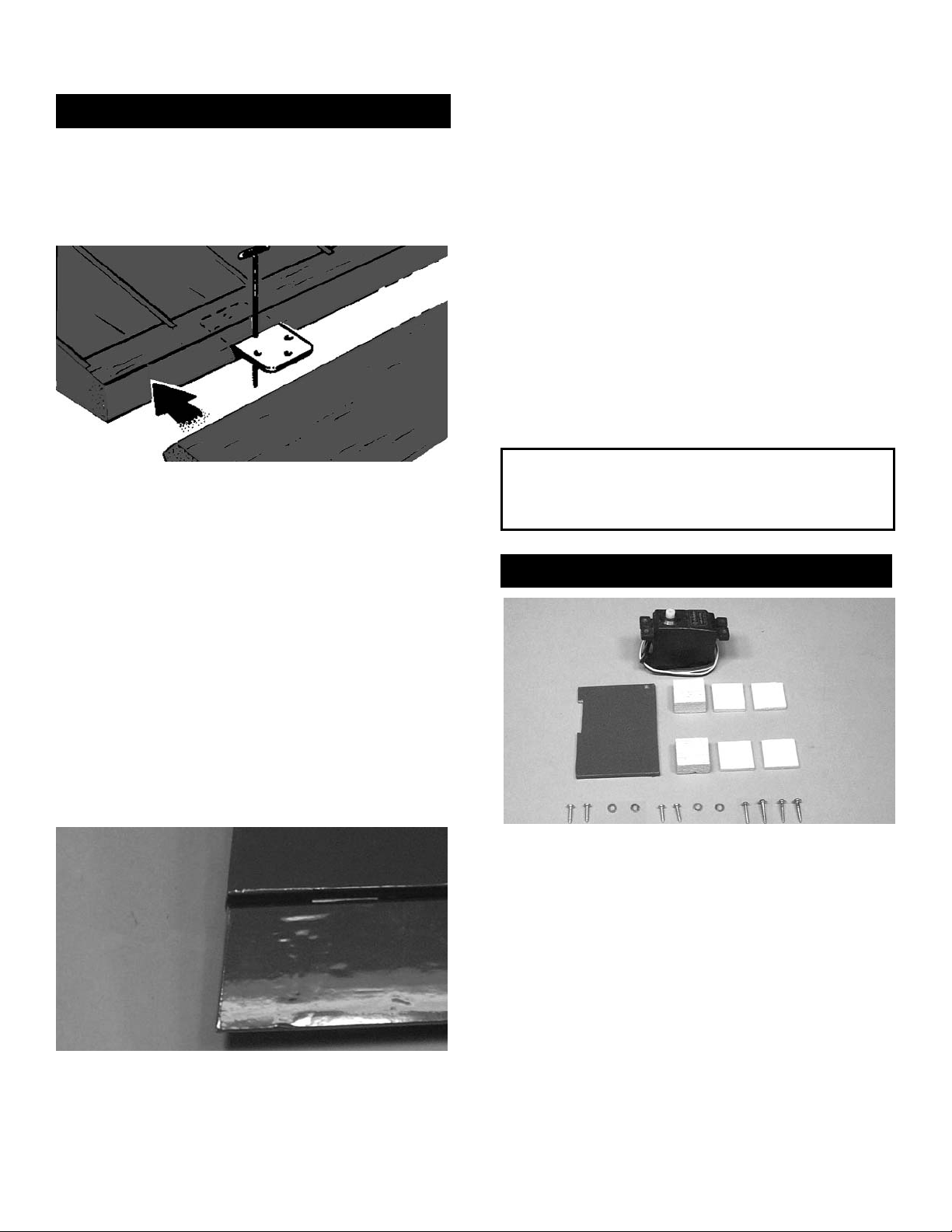
8. Place the servo door on the wing and drill a
1/16” hole on each corner. Screw the door to
the plate, using the #2 x 3/8” screw and the
#2 washer supplied with the kit.
Repeating the above steps, mount the sec-
ond aileron servo.
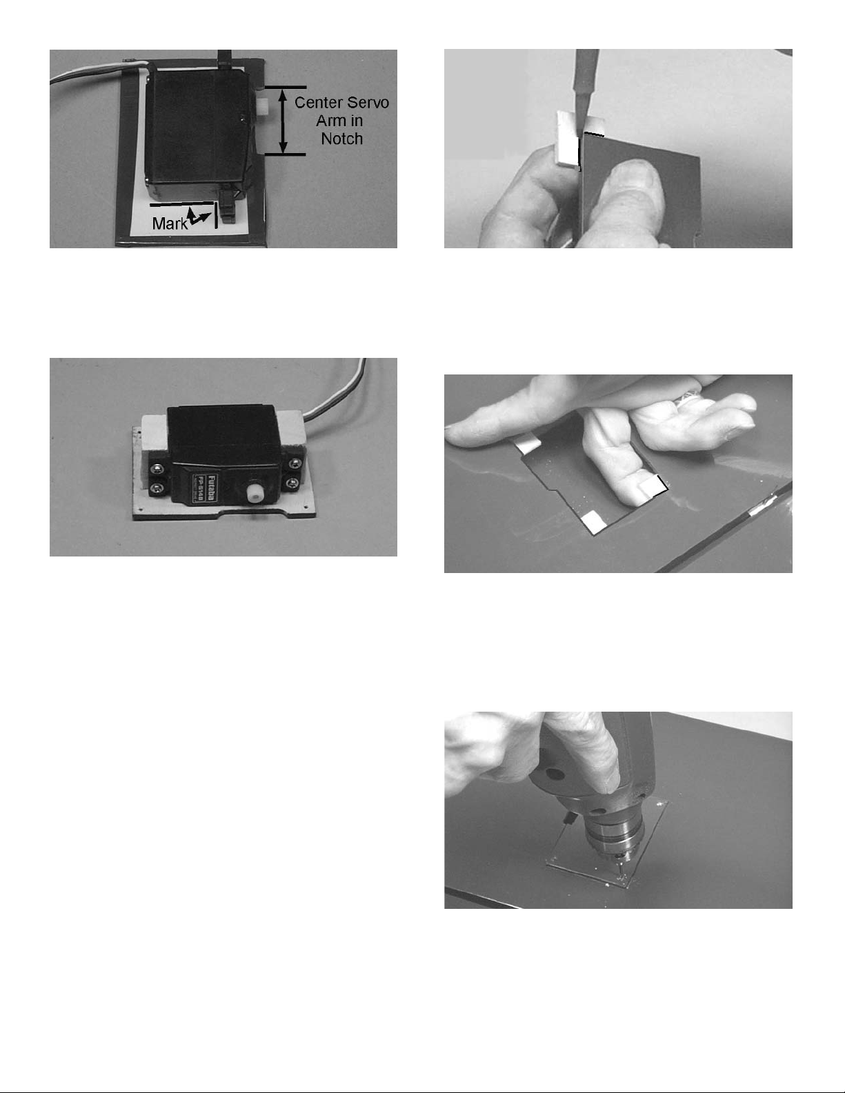
3. Remove the servo from the door. Spread
epoxy on the servo mounting blocks and
glue them in place along the line just drawn,
making sure the wood grain runs vertically.
4.
When the epoxy is dry, drill 1/16” holes and
mount the servo onto the blocks with the
mounting screws supplied with the radio.
Repeat these steps to mount the other
aileron servo.
2. With the servo door upside down on the
work surface, place the servo on top of the
door with the servo arm post centered vertically and horizontally with the servo door
notch. Mark the location of the servo, as
above.
6. Hold one of the servo plates in place against
one corner of the servo door, locating it in
such a way that the tab does not interfere
with the servo.
Mark the servo door-edge location on the
plate.
7. CA glue the plate to the corresponding cor-
ner of the servo hole in the wing.
Follow the same procedure with each of the
other three plates.
NOTE: Plates will fit into the corner differently,
depending on the servo used.
5
Page 6
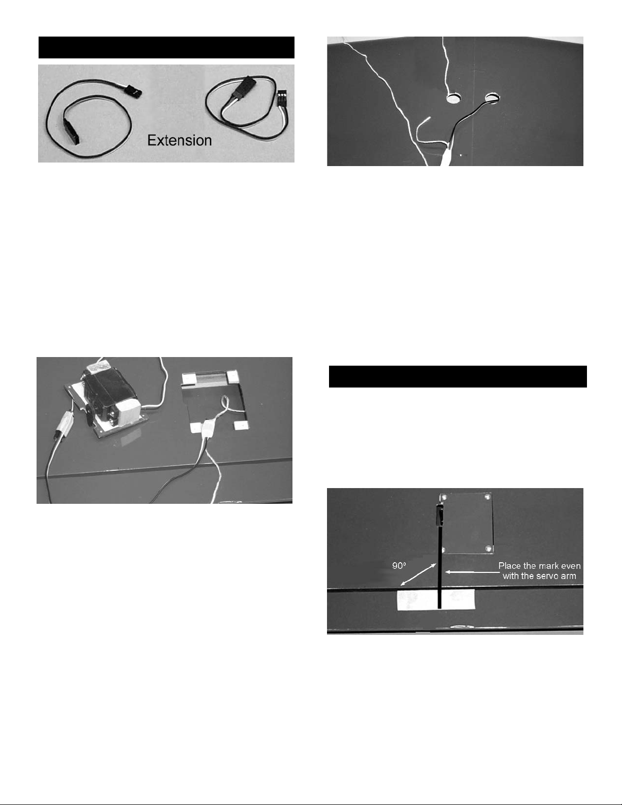
Aileron Extension Installation
1. Gather the following items.
(2) 12” extension wires
NOTE: Before starting, remove the servo door and
make sure the length of one servo wire, when
plugged into the 12” extension, is long enough
to reach to the center of the wing. If necessary, add
an additional extension to reach the center of the
wing.
IMPORTANT! To ensure that any connections
located inside the wing will not come loose, either
when the wires are pulled, or during flying, always
tape them securely together with electrical tape.
2. Remove servo door and, making sure to use
the correct servo for the opening, attach the
servo wire to the12” extension and securely
tape connection.
NOTE: Before continuing, make sure the other end
of the string inside the wing, next to the second
aileron hole, is taped firmly to the wing, so that it is
not pulled out by mistake. (If it becomes necessary
to reinsert this string into the wing, tie a 6-32 nut to
the end of the string and feed it back into the wing.
The nut will easily fall through the wing rib holes.
Tie the other end of the extension to the
string that exits the servo opening and tape
this connection, also.
3. Grasping the string in the hole in the center
of the wing, SLOWLY pull until the end of the
12” extension comes out of the hole. Work
the string back and forth to get the extension
plug to go through the cutouts in each rib.
Pull gently and have patience.
4.
Tape the extension securely to the wing, so
that it will not slide back in while you are
working.
Repeat these steps for the other half of the
wing, so that both servo extensions are exiting the holes in the center of the wing..
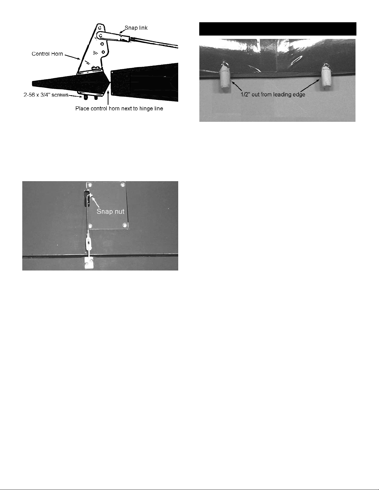
Control Horn Installation
1. Collect the following items:
(2) Large control horn with back plate
(4) 2-56 x 3/4” screw
(2) 1/16 x 7” threaded wire
(2) Snap-link
(2) Nylon snap nut (molded 6-up - see photo in
Engine Pushrod Installation)
2. Replace the servo door and screw it down
onto the wing.
3.
Make a mark at a 90º angle to the trailing
edge and in line with the servo arm.
6
Page 7
Wing Dowel Installation
5. Thread a snap-link on the end of one of the
1/16 x 7” threaded rods.
Place the snap-link in the second-from-the-
top hole on the control horn.
6.
Making sure the aileron is in neutral position,
mark where the wire meets the hole on the
servo arm.
Put a 90º bend (or a z-bend, if preferred) in
the wire, as shown above, and then attach
the wire to the servo arm with a snap nut.
Finally, put a drop of glue on the snap nut.
Repeat these steps for the other aileron.
4. Position the control horn so that the snap
link holes are right next to the hinge line.
Using a 3/32” drill bit, make a pilot hole in
each screw location, and then mount the
control horn, using the 2-56 x 3/4” screws.
1. Using epoxy, mount the 5/16 x 1-3/4” dowels
into the holes in the leading edge of the bottom wing. Make sure to leave about 1/2” of
dowel sticking out of the front of the wing.
You may wish to slighly taper the exposed
dowel ends for ease of insertion into the fuse
holes.
Now set the bottom wing aside until later.
7
Page 8
1. Collect the following parts.
(1) Fuselage
(1) Servo tray
(2) Front cabane doubler
(2) Cabanes
(2) Cross brace
(4) 4-40 x 1/2” Socket head screw
(4) 4-40 x 3/8” Socket head screw
(4) #4 x 7/16” washer
(4) #4 washer (smaller)
(8) 4-40 lock nut
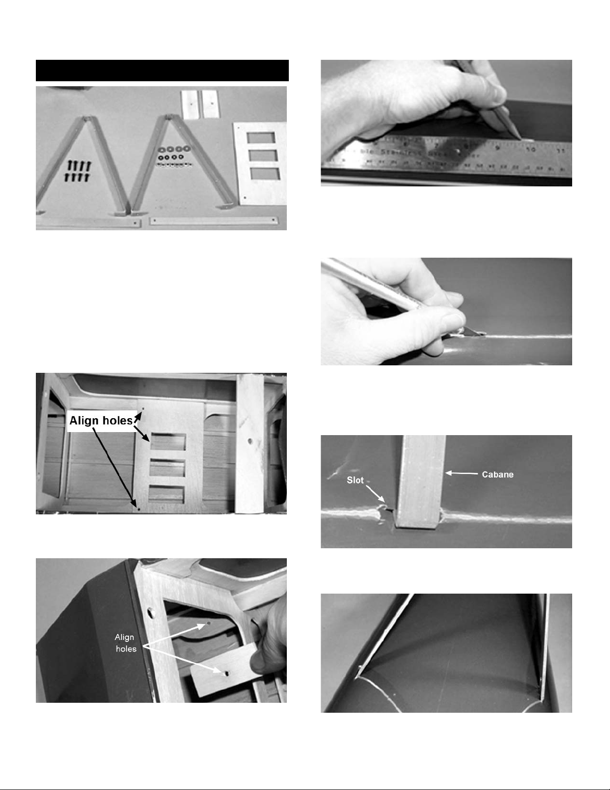
2. Being careful to align the holes and the
servo cutouts, CA glue the servo tray doubler into the fuselage.
4. Beginning at the front of the fuselage, make
a mark at 5” and at 9-3/4”. This will help
locate the pre-cut cabane slots on the
curved top of the fuse, behind the firewall.
5. Using a hobby knife, make a horizontal slit
from front to back, in the middle of the
cutout, as shown.
Slit all four cutouts in the same way.
FUSELAGE ASSEMBLY
Cabane Installation
3. Glue the front cabane doublers over the
holes in front of the fuselage former. Again,
make sure the holes in both the doubler and
the fuselage are aligned.
6. Gently push one side of the cabane into the
front fuselage slot, until it falls inside.
7. Slip the other side of the cabane into the cut
on the opposite side of the fuselage.
8
Page 9
2. Locate the pre-cut hinge slots and, using a
hobby knife, make sure all slots in the stabilizer, elevators, rudder, and fin are cleanly
cut.
Test the size of each slot by sliding a hinge
halfway into the opening. Then set the rudder and elevators aside until later.
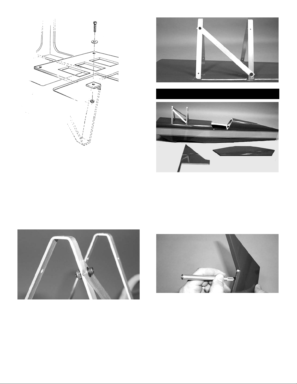
8. Turn the fuselage over and, working from
the inside, insert a 4-40 x 1/2” screw with
a #4 x 7/16” washer into the fuselage hole in
the cabane doubler and then through the
cabane hole. This is somewhat tricky, so
have patience.
When the screw protrudes through the
cabane hole, cap it with a 4-40 locking nut
and tighten.
Repeat these steps at each of the three
mounting points to complete the cabane
installation.
9. Insert a 4-40 x 3/8” screw and washer into
the cross brace in the top side hole of the
front cabane and secure with a 4-40 locking
nut.
Then, mount the other end of the cross
brace into the rear cabane, as shown below.
Repeat with the other cross brace.
Stabilizer/Fin Installation
1. Collect the following items.
(1) Fuselage
(1) Horizontal stabilizer
(1) Vertical fin
(2) Elevators
(1) Rudder
(1) 5ft. Length of string (not included in kit)
9
Page 10
3. Locate the pre-cut stab cutout by feeling
along the fuse side in the area where the
stab should go.
Remove the covering over the stab slot on
both sides of the fuselage.
4. Mark the center of the stab on both the trail-
ing and leading edge.
5. Slide the stab into the back of the fuselage,
using the center marks as a guide. Measure
the stab, as shown, to make sure it is properly centered.
NOTE: It is also possible to see the centermarks
through the fin cutout.
6. Turn the fuse around, and determine the
vertical centerline of the fuse top front.
Measure to the center point on the top of the
fuselage. DO NOT CENTER ON THE FIREWALL THRUST LINE.
7. Place a pushpin on the center mark and tie
a string around the pushpin.
8. Stretch the string back until it touches the
outer tip of the stabilizer leading edge. Mark
the string and then measure back to the
other outer L.E. tip, making sure the distance
is the same.
10
Page 11

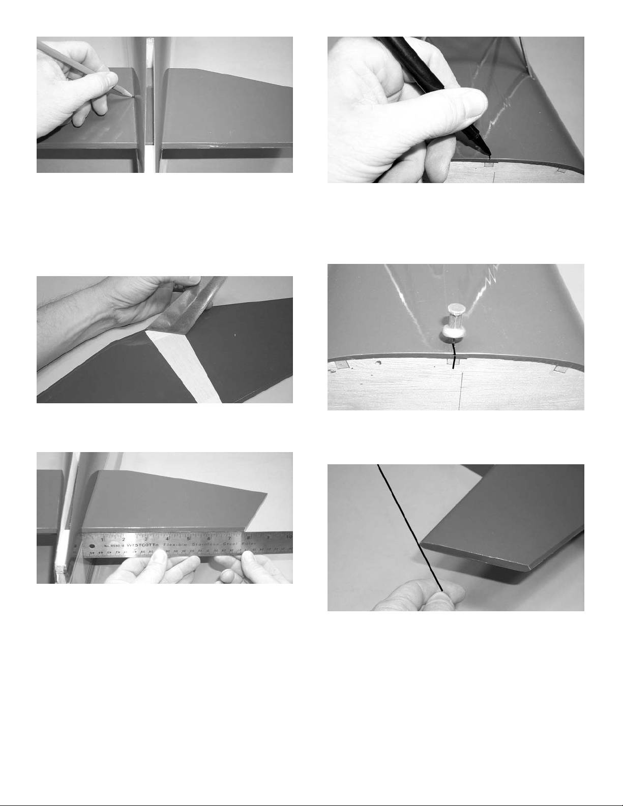
9. When the stab is correctly aligned, outline on
both the top and bottom of the stab where it
meets the fuse, as shown.
10. Remove the stab from the fuselage. Being
careful to not cut into the wood, and work-
ing about 1/8” inside the outline on the stab,
lightly cut away the covering on both the bottom and top of the stab.
Replace the stab on the fuselage, but DO
NOT GLUE AT THIS TIME.
11. Slide the fin into the back slot and push the
fin front down into the top slot.
When the fin is all the way down and flush to
the fuselage, mark a line on both sides of the
fin where it meets the fuselage.
12. Locate the solid wood area under the cover-
ing and place marks on the line where the
wood ends. Make sure not to mark any open
frame areas.
13. Staying at least 1/4” away from the open
frame, carefully remove the covering on
those areas of the fin (both sides) that are
inside the fuselage.
14. Replace the fin on the fuselage and check to
see that the fit is good and the alignment
square.
When you are satisfied with the fit, remove
the fin.
Mix 2-3 tablespoons of epoxy and, using a
stick or an acid brush, spread epoxy down
inside the fin slot, along the walls of the slot,
and on top of the stab.
Glue the stabilizer and the fin to the fuselage
and, using the measuring string and a 90º triaangle, check to see that the tail assembly is
square. Allow to dry thoroughly.
11
Page 12

15. When dry, turn the fuse over and wick a few
drops of thin CA gluet along the stab/fuse
joint.
Control Horn Installation
1. Collect the following parts:
(2) Elevator
(2) Large control horn with backplate
(4) 2-56 x 3/4” Pan head screw
(1) Rudder
(1) Double-sided control horn
(1) 2-56 x 1/2 Phillips head screw
NOTE: You will be making both a LEFT and a
RIGHT elevator.
2. Mark 1” in from the inside edge along the
hinge line of the elevator.
3. Place the control horn as shown, with the
center aligned on the 1” mark and the snaplink holes directly above the hinge line.
On the elevator, mark the location of the
mounting holes on the base of the control
horn and drill, using a 3/32” bit. Then mount
the control horn as shown, using 2-56 x
3/4” screws.
Remembering that you are making both a
lef
t and a right elevator, repeat the previ-
ous steps to mount the control horn on the
other elevator.
NOTE: The double-sided control horn is two control
horns screwed together back to back.
4. Place the control horn on the rudder as
shown. The control horn must be even with
the hinge line. When you are satisfied with
the fit, mark the location of the screw hole
and drill, using a 3/32” bit through the rudder.
Place the two control horns together and
mark the bolt location on the second control
horn base.
Drill the second control horn using a 1/16”
bit.
Mount the control horn, using the 2-56 x 3/4”
screw.
Elevator/Rudder Hinge Installation
1. Collect the following items.
(1) Fuselage/Tail Assembly
(2) Elevators
(1) Rudder
(9) Jet hinges
12
Page 13

Landing Gear Installation
1. Collect the following items:
(1) Landing gear
(3) 6-32 x 3/4” socket head screws
(3) 6-32 blind nuts
(3) #6 washers
(1) Fuselage
2. Place the main gear on the bottom of the
fuselage, as shown.
Locate the center of the fuselage and mark
it. Then mark the center of the gear and line
up both center marks.
3.
Move the gear back until it touches the stop on the
back of the gear block. Then mark the hole locations and drill a 5/32” hole at each location.
4.
With the screws and the washers through
the gear, pull the blind nuts up tight inside
the fuselage.
2. Take three hinges and, as with the aileron
hinge installation, insert the hinge into the
elevator, using straight pins to ensure the
hinge stays centered between the stabilizer
and the elevator.
Slide the exposed side of the hinge into the
slots in the stab until the pins touch both the
stab and the elevator.
3. Holding the elevator and stab together, place
a straight pin between the stab and the elevator, at the elevator tip. This pin will create
a 1/32” gap between the elevator and the
stab.
Remove the pins in each hinge and, keeping
the elevator/stab assembly in position, apply
3 or 4 drops of thin CA to each hinge, on
both the top and bottom sides of the stab.
Allow ten minutes for the CA to cure before
flexing the elevator. Then install the second
elevator.
4. When the elevators have cured, install the
hinges and mount the rudder, using the
same techniques used for the other hinged
surfaces.
NOTE: Before gluing, make sure the top of the rud-
der is even with the top of the fin.
13
Page 14

Tailwheel Installation
1. Collect the following items:
(1) Tailwheel bracket
(1) Tailwheel
(2) Springs
(2) 2-56 x 1/2” Philips head screw
2. Locate the three holes under the covering on
the bottom rear of the fuselage. Remove the
covering from all three holes.
NOTE: The hole nearest to the nose of the model is
the exit hole for the receiver antenna. The other two
holes are for the tailwheel assembly.
14
5. One of the bracket collars has two holes
threaded into it, one on each side. This one
is the top one.
Put the bottom bracket collar on the axle and
insert it through the spring bracket.
Put the top collar bracket on top and tight-
ened the two set screws.
6.
Screw one of the two threaded rods on each-
side of the top bracket collar.
Screw the nylon horn fittings on each end of
the threaded rod.
7.
Put the tail wheel on the axle and retain with
the wheel collar.
9. Mount the tail wheel assembly on the rear of
the fuselage using the two 4-40 screws.
3. Mount the tailwheel using the 4-40 x 1/2”
phillips head screws, as shown above. Hook
the springs between the rudder control horn
and the tailwheel bellcrank. It may be necessary to open the end of the springs in order
to connect them to the control horns and the
bellcrank.
1. Collect the following items:
(1) Engine
(1) Motor mount
(4) 6-32 x 3/4” socket head screw
(4) 6-32 blind nut
(4) #6 washer
(4) #8 x 1” pan head screw
Motor Mount/Engine Installation
Page 15

Align Marks
REMEMBER, the following pictures and instruc-
tions may vary slightly, depending on the equipment
you are using.
2. Using the alignment marks, center the motor
mount on the firewall and tack glue.
3. Drill a pilot hole through the motor mount,
using a 1/8” drill bit.
Remove the motor mount and re-drill the
holes, using a 5/32” drill bit.
4. Install the motor mount blind nuts into the the
back of the firewall with the 6-32 x 3/4” socket head screws and the #6 washer.
NOTE: The top left blind nut may rub on the hori-
zontal former. When the motor mount is
installed, tighten this blind nut down last.
5.
Using the 6-32 x 3/4” socket head screws,
install the motor mount onto the firewall.
Check to see that all of the alignment marks
on the motor mount match the marks on the
firewall.
You may wish to put thread lock on the
screws at this time.
7. Using the drill, lightly mark the locations of
the engine mounting holes.
Set the engine aside and, using the 5/32”
drill bit, finish drilling the holes.
6. Place the engine on the motor mount, mak-
ing sure the propeller drive plate is 5-5/8”
away from the firewall.
8. Replace the engine on the motor mount and
install the engine using the #8 x 1” screws.
Elevator Servo Installation
1. Collect the following items:
(2) 2-1/4 x 3/8 x 1” servo block
(3) Radio servo
(12) Servo mounting screw
2.
Make sure the servos fit snuggly in the servo
tray.
3. Glue the servo blocks at each end of the
middle servo hole.
15
Page 16

16
Elevator Pushrod Installation
1. Collect the following items:
(3) .072 x 10” threaded wire
(3) Nylon snap link
(1) Single-hole pushrod plug
(1) Double-hole pushrod plug
(1) 36” fiberglass pushrod tube
(2) 1/8 x 24” nylon guide tube
(1) Elevator wire drawing(Back of booklet)
2. Using a fine-tooth saw or modeling knife, cut
the fiberglass pushrod to a length of 16-1/2.”
This may be accomplished by rolling the
tube under the blade.
3.
Measure 1” back from one end of the
pushrod and drill a 5/64” hole completely
through both sides. This hole will hold the
elevator wires.
4. Measure 1” from the other end of the
pushrod and drill a 5/64” hole HALFWAY
THROUGH the pushrod. TAKE CARE TO
DRILL ONLY THROUGH ONE SIDE.
5. Using the 5/64” drill, and holding a pushrod
plug, as shown, drill out the center of the plug
to form a tube. Repeat for the other plug.
6. Using the Elevator Wire Drawing, place a
threaded 10” wire over Drawing #1, as
shown.
Starting at the threaded end, measure back
to the first bend and mark the wire. Then,
carefully bend the wire to match the drawing.
7. Mark the second bend and then bend the
wire accordingly.
Repeat this process for a second threaded
wire.
Page 17

12. When the bent tip is exiting the hole in the
pushrod and the plug tightly meets the
pushrod, apply CA glue to the joint.
13. Insert both of the nylon guide tubes into the
exit holes located closest to the stab on each
side of the model.
Look through the cockpit to see the guide
holes in the former. Then, thread the guide
tubes through the guide holes.
14. When the nylon tubes have been pushed
through the fuselage, insert the two wires
from the end of the pushrod into the tubes.
Then, slide the pushrod back down through
the fuselage, allowing the nylon tubes to
guide the way until the two ends of the
pushrod come out of the exit holes on either
side of the airplane.
11. Place the single-hole plug onto the wire and
then bend the wire, as shown.
Referring to the drawing, cut the wire after the
bend and slide the end of the wire into the
single-hole end of the pushrod.
15. Once the wire has exited the fuselage,
remove the nylon tubing from the end of the
wires.
8. With the pointed end of the plug facing the
threaded end of the wired, slide the doublehole plug onto the non-threaded end of the
wires.
Measure 2-3/8” down from the second bend
and make a 90º bend. Then, cut the wire
after the bend, so that it will fit in the
pushrod.
9. Insert the two wires into the double-hole end
of the pushrod until the bent ends slide into
the holes.
Slide the plug as far as it will go down into
the pushrod. Then, CA glue the plug to the
pushrod.
10. Using Drawing #2 as a template, mark the
location of the bend on the third threaded
wire.
17
Page 18

16. Thread the snap-links onto each of the wires,
until the the wire shows in the middle of the
snap-link.
17.
Connect the snap-link to the second hole of
control horn.
18. Thread a snap-link onto the servo-end of the
pushrod and attach to the elevator servo.
Rudder Cable Installation
1. Collect the following items:
(2) 34” stranded cable
(4) 1/16 threaded couplers
(4) Snap-links
)2) 1/8 x 24” nylon tubing
2. Using flux and silver solder, solder a thread-
ed coupler onto the end of the cable.
3.
From the coupler end, and including the cou-
pler itself, measure 30 inches and mark the
cable. Then cut it with a wire cutter.
Now, making sure the cable is all the way
into another threaded coupler, solder it to the
cut end. The total length of the finished cable
should be 31”.
Repeat the above steps to make a second
cable to the same length.
4.
Install the cables by using the guide tubing
and threading them through the fuselage, as
was done with the elevator pushrod.
Wash the soldered coupler/cable assembly
with soap and water.
5.
Place a snap link on each end of each cable.
6. Connect two snap links to the center servo,
as shown, and the other two snap links to
the rudder control horn.
18
Page 19

5. Place the cockpit insert on the fuselage and,
while pressing down on the insert, tape the
cockpit insert down.
6.
Using a 1/16” bit, drill four holes 1/4” up from
the cockpit bottom and along the centerline
that extends from under the insert.
7. Place the canopy over the cockpit insert and,
making sure it is straight on the fuselage,
tape it securely.
Drill four holes in the canopy at the same
locations as those drilled in the cockpit insert.
8. Remove both the canopy and the cockpit
insert, and then remove the tape from the
side of the fuselage.
Replace the insert on the fuselage and put the
canopy in place over it. Screw down both parts
with the #2 x 3/8” screws and #2 washers.
Engine Pushrod Installation
1. Collect the following items:
(1) .063 x 16-3/4” wire
(1) 1/8 x 24” nylon guide tubing
(1) Snap nut wheel
(1) Pushrod connector
(1) 4-40 x 1/4” socket head screw
(1) 20” length of fuel tubing
NOTE: The following photos and instructions are for
mounting a 4-cycle engine. Other engines might
require different steps for installations.
Canopy & Cockpit Installation
Make sure the cables are tight and that the
rudder does not move without moving the
servo.
NOTE: This servo works best if it has ball bearings.
1. Collect the following items:
(1) Cockpit insert
(1) Canopy
(4) #2 x 3/8” sheeet metal screw
(4) # 2 washer
2. Carefully cut the cockpit along the scribe
line.
3.
Place a strip of masking tape along both
sides of the fuselage cockpit opening.
4. Find the center of the cockpit doubler and
make a mark on the tape at the center point.
19
Page 20

2. Mark 1/4” from the end of the .063 wire and
make a 90º bend.
3.
Cut the wire to a length of 12-3/8”.
4. Cut off a piece of nylon guide tube 9-1/2”
long.
5. With the engine in place on the motor mount,
mark the location for the throttle pushrod on
the firewall.
6. Remove the engine and drill a 1/8” hole for
the pushrod in the firewall.
7.
Next, drill two 1/4” holes for the fuel tubing.
Take the 20” length of fuel tubing and pass
equal amounts of the tube into each of the
holes, so that equal lengths of tubing are
inside the fuselage.
8. Insert the 9-1/2” guide tube through the front
of the firewall back to the throttle servo.
Make sure the tube goes through the hole in
the former, as shown above.
NOTE: A short length of guide tubing should extend
out the front of the firewall.
9. Holding the engine in your hand, take the
bent end of the .063 wire and place it on the
throttle arm of the engine. Then, slide the
other end of the wire into the guide tube.
Make sure the throttle wire goes through the
tubing in the fuselage and over the top of the
throttle servo.
10. Place the throttle wire through the hole in the
pushrod connector and slide the servo arm
on the wire to the top of the servo, as shown.
NOTE: It may be necessary to bend the wire to pre-
vent any binding.
11.
Twist the servo until the arm is pointing
towards the engine and then push the wire
forward until it stops moving.
Tighten the setscrew on top of the pushrod
connector. Final adjustment can be made
later, when the rest of the radio is installed.
20
Page 21

2. Check to see if any part of the engine muffler
or exhaust header will interfere with the fuselage. If necessary to create clearance,
remove a portion or the entire tab that
extends beyond the firewall.
3. Place the piece of clear plastic over the top
of the engine. The end of the plastic should
extend just past the cylinder head.
4.
Mark where the engine contacts the plastic.
Remove the plastic and, using the moto tool,
cut out the engine area until the plastic fits
over the top of the motor and lies flat on the
fuse side. Then, tape the edges of the plastic to one side of the fuselage.
Using the moto tool, cut away the bottom of
the cowl at the point where it hits the landing gear. Take off small amounts at a time
and keep measuring the cowl until it will slide
back to a point that is 1/16” behind the
engine drive washer.
NOTE: If using the engine pictured in these instruc-
tions, the measurement from the firewall to
the front of the cowl will be 5-3/8”.
7. Securely tape the cowl to the fuselage, so
that it will not move. Once taped, measure
the cowl again to make certain its position
has not shifted.
8.
Place a piece of masking tape on the side of
the fuselage just above the landing gear and
long enough so that it extends 3” onto the
cowl and behind the landing gear.
Placing the plane on its side, measure 1-1/4
above the landing gear and make a mark on
the tape.
From the mark, on a plane parallel to the yel-
low striping, measure 1-3/8” and make a
second mark.
Drill a 1/16” hole on the second mark for the
lower cowl screw.
Turn the aircraft over and repeat the above
steps, drilling a bottom hole on the other
side.
6. Slide the cowl under the plastic.
CAUTION! WHEN CUTTING THE COWL, ALWAYS
WEAR PROTECTIVE EYE GEAR AND A LONGSLEEVE SHIRT. CHANGE CLOTHES AND WASH
AFTER CUTTING.
Cowl Installation
1. Collect the following items:
(1) Fiberglass cowl
(4) #4 x 3/8 sheet metal screws
(4) #4 washers
(1) 4 x 12” clear plastic
5. Lift up the untaped side of the plastic and
remove the engine.
21
Page 22

. Place a piece of masking tape down the cen-
ter of the wide yellow trim stripe.
Measuring up 1-3/8” from the bottom of the
yellow stripe, make two marks and draw a
line on the tape, parallel to the yellow stripe.
Make a third mark on the tape, even with the
back of the landing gear. From this point,
measure forward 5-7/8”.
Drill a 1/16” hole at this location for the top
cowl screw.
10. With the fuselage on its left side, trace the
cutout for the engine onto the cowl.
Remove the cowl and, with a moto tool, slow-
ly remove the fiberglass INSIDE the cutout
outline. Work slowly and carefully, until the
cowl matches the clear plastic piece.
Remember, if the fiberglass is damaged dur-
ing this process, it can be repaired only with
epoxy glue.
NOTE:You may wish to make a cutout in the front of
the cowl, at the point where the engine prop washer
sticks out, that is large enough to allow the engine to
vibrate without touching the cowl.
Fuel Tank Installation
1. Collect the following items:
(1) Fuel tank
(1) Fuel tank platform
(2) #30 rubber bands
(2) Brass tube
(1) Large nylon cap
(1) Small nylon washer
(1) Rubber stopper
(1) #4 x 1” screw
(1) Fuel tank klunk
(1) 6” length of white fuel tubing
(1) 1/4 x 3/8 x 2-1/2” fuel tank stop
(1) 1/4 x 3/8 x 5-1/2” fuel tank support
CAUTION! The white neprene stopper and the fuel
tubing provided with this kit are FOR GLOW FUEL
ONLY; DO NOT USE THESE PARTS FOR GASOLINE.
2. Insert both brass tubes through the wide end
of the rubber stopper. Leave 1/2” extending
out the front of the tank.
Place the small nylon washer on both tubes,
as shown, making sure that one of the tubes
extends 1” past the washer. This tube will be
for the klunk pickup.
Cut tube as necessary.
22
Page 23

10. Measure 2-7/8” from the landing gear block
on both sides of the front former. Glue the
fuel tank support stick across the opening the
former.
3. Bend the other tube, at the angle shown,
until it nearly reaches to the fuel tank wall.
This is the vent/overflow tube.
4.
Insert the stopper assembly into the fuel tank
until the vent tube is up inside the “bubble” in
the fuel tank wall. Remove the assembly
and trim the vent tube, if necessary.
5. Install the klunk on the white fuel tubing.
Mount the other end of the fuel tubing onto
the brass outlet tube in the stopper.
6. Again place the stopper assembly into the
fuel tank. If the klunk is touching the back
wall of the tank, trim it as needed.
7.
Place the large nylon cap onto the two brass
tubes.
When satisfied with the fit of the entire stop-
per assembly, tighten the #4 x 1” screw into
the center of the stopper. Take care to not
over-tighten the screw.
8. Referring to the above photo, place the fuel
tank on the fuel tank platform.
Secure the tank to the platform with the rub-
ber bands.
9.
Glue the 1/4 x 3/8 x 2-1/2” balsa stop in front
of the tank, as shown. When the glue has
set, replace the rubber bands with electrial
tape, so that the tank is well-secured to the
platform.
23
Page 24

11. Reach into the fuselage and place the fuel
tubing onto the brass fuel tank tubes. Note
which tube is the vent and which is the outlet.
12.
From the front of the firewall, pull on the fuel
lines to remove any slack.
13. Complete the fuel tank installation by gluing
the rear of the fuel tank platform onto the support stick.
Receiver Installation
1. Insert the Y-harness in the aileron plug in the
receiver and then wrap both the receiver and
the battery in the !/4” foam included in this
kit. Secure with rubber bands.
24
Foam Not
Included
2. Plug the switch into both the battery and the
receiver.
Next, plug the elevator, rudder, and throttle
servo wires into the receiver.
3.
Place the battery and the receiver into the
compartment in front of the servos. Remember to keep the antenna and the Y-harness
outside of the compartment so that the
aileron servo wire can be easily plugged into
the receiver.
Place a piece of scrap wood across the
receiver and battery pack to keep them in
place.
4.
Insert the receiver antenna into the pre-
installed tube in the left side of the fuselage
and slide the antenna down the tube until it
exits out the hole at the rear of the fuselage,
just in front of the tailwheel.
5. Turn on the receiver and transmitter and put
all control surfaces in neutral position. Then
insert the center screw into each of the servos.
CAUTION: Make sure all servo arms are tightened
onto the servos.
1. Collect the following items:
(2) 3” wheel
(2) Axle
(2) Axle locking nut
(4) 3/16” wheel collar
(4) 6-32 x 1/8” set screw
(2) Wheel pant (right and left)
(4) #2 x 7/16” sheet metal screw
Wheel & Wheel Pant Installation
Page 25

NOTE: There are several ways to mount wheel
pants. Following are two different methods.
4.
Place the wheel pant against the back of the
axle, next to the landing gear. Make a mark
on the axle where the outside of the axle hits
the wheel pant.
Check to make sure that the wheel and both
the inside and outside wheel collars will fit on
the axle. If the fit is right, cut the axle at the
point of the mark.
Alternatively, mark the wheel pant where the axle
strikes the wheel pant and drill a 3/32” hole at that
location on the outside of the wheel pant. Let the
axle exit from inside the wheel pant through this
hole. This will help support the wheel pant when flying off a grass or rough field.
2. Insert the threaded part of the axle through
both sides of the landing gear and tighten
the locking nut on each axle.
Thread the 6-32 x 1/8” set screw into each of
the four 3/16” wheel collars and place one
wheel collar onto each axle.
3. Slide the wheel pant over the axle and up
against the landing gear. Make a mark on
the wheel pant where it hits the axle.
25
5. When satisfied with the fit of all the compo-
nents, mount the wheelpants, wheels and
the remaining (outside) wheel collars onto
the axle.
Turn the aircraft right-side up and level the
stabilizer.
When the wheel pant is level, drill a 1/16”
hole through both of the landing gear holes
and into the wheel pant.
Secure the wheel pant to the landing gear
with #2x 3/8” sheet metal screws.
6. Make sure the wheel pant is horizontal to the
tabletop by measuring from center of the
front tip and the center of the back tip, as
shown above.
Page 26

1. Collect the following items:
(1) Bottom wing
(1) Top wing
(1) Bottom wing bolt plate
(2) I-struts
(8) 4-40 x 1/2” sock head screw
(8) 4-40 blind nut
(8) #4 washer
(1) 6-32 x 1” socket head screw
(1) 6-32 blind nut
(1) #6 x 3/34” washer
(2) 4-40 x 1” socket head screw
(2) 4-40 locking nut
(2) #4 x 7/16” washer
(10) #4 washer
FINAL WING INSTALLATION
2. Take the bottom wing and locate the hole in
the center of the wing close to the trailing
edge. Carefully remove the covering from
over the hole on both the top and the bot-
tom of the wing.
Next, find the hole in the center of the wing
bolt plate and, again, remove the covering.
3.
Align the hole in the wing bolt plate over the
hole in the bottom of the bottom wing.
Draw the outline of the plate on the wing
and, taking care to work 1/4” inside the
outline, remove the covering on the wing in
the area where the plate will rest.
Making sure the holes are aligned, CA glue
the plate onto the wing bottom.
4. Working from inside of the fuselage wing
opening, push the 6-32 blind nut in the hole
in the center of the wing block until it will go
no further.
Take the 6-32 x 1” screw and the #6 x3/4”
washer and screw them through the block
into the blind nut. Tighten until the blind nut
is seated well up into the wing block.
5.
Now, temporarily remove the 6-32 screw and
washer and place the bottom wing onto the
fuselage.
Plug the servo extensions from the wing into
the Y-harness.
Insert the two front wing dowels into the bot-
tom of the wing saddle. Then, using the 6-32
screw and washer, screw the back of the
wing to the fuselage
6. With the plane right side up, place the cutout
in the top wing onto the center cabanes.
Next, slide the tabs on both the lower wing
and the top wing into the slots of the I-struts.
The curve of the wing will match the curve of
the bottom of the I-strut.
Wing/I-strut Installation
26
Page 27

4. Connect the aileron coupler assembly to the
aileron control horns, as shown.
7. Working from the outside (towards the fuse-
lage) insert the 4-40 x 1/2” socket head
screws with #4 washers through the holes in
the I-strut.
Attach a 4-40 blind nut to the screw and
tighten until the blind nut is flush with the
back of the I-strut.
Repeat with the other I-strut.
CAUTION: Do not over-tighten these screws, as
doing so will crush the I-strut onto the tab and make
it difficult to remove it from the wing.
8. Referring to the above drawing, bolt down
the center and then the rear of the top wing.
Aileron Coupler Installation
1. Collect the following items:
(4) Small control horn
(8) 2-56 x 1/2” pan head machine screw
(2) .072 x 10-1/2” double threaded wire
(4) Mini snap link
2. Mark locations for the control horns on the
outer edge of each aileron (top and bottom
wing) by measuring 8” in from the aileron tip.
With a wire cutter, remove the top of the con-
trol horns, so that only one hole remains on
each horn.
Thread a mini-snap link to each end of the
double-threaded wire.
3. Using the pan head screws, mount two con-
trol horns on the top of the bottom wing and
two on the bottom of the top wing.
27
Page 28

Decal Installation
Spinner Assembly
1. Clean model surfaces thoroughly before
applying decals.
2.
Cut decal sheets apart in sections, as need-
ed.
Fold decal in half, front to rear. Open at fold
and lay decal out straight. The protective
backing will bubble away from the decal at
the fold. Using a scissors, cut the backing
along the bubble, removing a strip of backing
about 1" wide. Carefully position the decal
on the model and stick in place. Then, working from the center, rub the decal down while
peeling off the backing.
28
A 3" CGP 4-Pin Snap-On Spinner is included with
your Ultimate ARF. It is a rugged precision molded
spinner that does not require any special mounting
nuts or screws. CAREFULLY READ THE SPINNER
INSTRUCTIONS AND WARNINGS INCLUDED
WITH THE SPINNER. Although a spinner helps
reduce the chance of injury from a rotating prop,
extreme caution always must be used when the
engine is running.
Balancing the Model
IMPORTANT: NEVER NEGLECT THIS STEP
WITH ANY AIRPLANE. If you try to fly a plane with
the balance point behind the recommended range,
you run the risk of having an unstable aircraft and
the strong likelihood of a crash. TAKE THE TIME
TO PROPERLY BALANCE YOUR MODEL!
To determine the Center of Gravity, measure back
on the fuselage 2-3/8” from the leading edge of
the bottom wing. The C.G. range for this aircraft
is 1-7/8” to 2-7/8”. It is recommended that you balance this model upside down. Add weight if necessary to achieve the proper balance.
Page 29

Fully-charged flight batteries
Radio transmitter
1 ½ volt starting battery & glo-plug clip
Fuel bulb or pump
Tools for tightening any parts that can vibrate
and loosen
Paper toweling for clean up
Extra props and an extra spinner
Prop wrench
Bottle of CA glue
Field Kit Checklist
Pre-Flight Activities
see that no signals are missed until you are at least
100 feet away. Only if the equipment works perfectly should any flights be attempted. Again, be
careful to not use your transmitter when anyone
else at the field is flying or testing on the same frequency!
After the range check, stand behind the model and
make sure the control responses are correct.
Moving the control stick to the right should give right
rudder (on a 3-channel set-up) or the right aileron
should go up (on a 4-channel set-up). Moving the
stick back or down on the Tx should move the elevator up, and vice versa.
Check also to see that your wheels operate properly Your throttle should open to permit full power
when the stick or tab is moved forward or up. Finally,
make sure that everything on your aircraft is neatly
and firmly in place-motor fastened down, servos
snugged down, receiver and battery wrapped in
foam rubber, tank properly supported, etc. Prop and
spinner must be tight. The receiver antenna must
be extended, not coiled up inside the model.
Nothing should be loose, or unfinished, or
unchecked.
With everything ready, the engine should be started
and broken in for a least a tank or two at no more
than moderate speed. While the engine is running,
make sure the control surfaces do not jitter or move
until you command them and that the throttle also
responds properly to your command.
Prior to going to the flying field, with radio batteries
fully charged, turn on both receiver (Rx) and trans
mitter (Tx) and actuate all controls many times until
you are satisfied with all functions.
Before beginning each day's flying, make a range
check of your equipment in accordance with the
manufacturer's instructions. In general, with transmitter antenna collapsed to 6"-8", you should have
an at least 100 foot range on the ground. To check
this, turn on both the transmitter and the receiver
switches, set the model heading away from you,
and walk away while transmitting signals. Watch to
29
Setting Control Surface Travels
SETTINGS
Gentle
Aerobatic
AILERON: 10º 12º
ELEVATOR: 12º 14º
RUDDER: 15º 23º
When beginning to fly your ULTIMATE, we encour-
age you to start out with the gentle settings,
regardless of your flying ability. Then, after you
have become familiar with the aircraft, move to the
aerobatic settings.
NOTE: Always use the furthest hole on all control
surfaces and adjust at the servo for proper throw.
Do not use the transmitter adjustment to set up the
control travels. The transmitter should be used only
for fine tuning.
It is not recommended that you fly this model with
the dual rate control HIGH RATES set at the “aerobatic settings” and the LOW RATES set at the “gentle settings.” The initial flights should be set up with
the “gentle settings” at the HIGH RATE and the
LOW RATES at 75% of the “gentle settings.” The full
F3A schedule can be flown very well with this setup.
Once the model is trimmed out, if a more “hot dog”
style of flying is desired, increase the control travels
with the same percent of LOW RATE.
Take-Off & Landing
Though the ULTIMATE is not difficult to control dur-
ing take-off and landing, it is important to not overcontrol. Make small smooth corrections until you
become familiar with the feel of your model. When
taking off, you will need to add a bit of right rudder.
Wait until there is plenty of airspeed and gently
rotate (about 1/8-1/4 up elevator), keeping the
wings level.
On landings, you will find that the ULTIMATE glides
better than most bi-planes. However, no bipe glides
as well do monoplanes. For the best landings,
approach the runway at high idle and go to low idle
about one foot above the ground, flaring to a 3-point
landing as you gently touch done.
Page 30

Developing your flying skills to include more varied
maneuvers is exciting and rewarding.. The ULTI-
MATE is an extremely capable aircraft and is able to
do advanced stunts. Here are a few you might try.
ADVANCED AEROBATICS
KNIFE-EDGE LOOP
This maneuver requires a powerful engine
LOMCEVAC
Roll to the left or right and hold a bit (10%) of top
rudder. When ready to start the loop, add more rudder.
Start out in a 45º climbing knife-edge. If you are
using left rudder for the knife-edge, snap-roll left (full
left rudder, left ailerons, and up elevator) 1-1/2 turns.
Then, holding full left rudder, give full down and right
aileron. Timing is the key, as well as power and
climb angle. Try it and hold on!.
30
Page 31

 Loading...