

Page 1
The Ultimate ARF
Wingspan: 60.5 in [1535mm]
Wing Area: 1250 in2 [80.6dm2]
Weight: 11.75 – 12 lb [5330 – 5445g]
Wing Loading: 22 oz/ft2 [67g/dm2]
Length: 66 in [1675mm]
Radio: 5-channel minimum
Servos: (6) Futaba 9001 servos, (1) Futaba 9202 servo (rudder),
(1) Futaba 3003 servo (throttle)
Engine .90 – 1.20 cu in [15 – 20cc] two-stroke,
1.20 – 1.50 cu in [20 – 25cc] four-stroke
INSTRUCTIONS
Welcome to the world of Ultimate fl ying! Now that you’re an
experienced R/C pilot, you’re ready to step up to a higher level
of aerobatic fl ying. And we’ve made sure this ARF version won't
disappoint. With the same fl ight characteristics as the kit version,
you’ll soon know why the Carl Goldberg Products Ultimate
has been America’s favorite sport biplane since 1990.
LIMITED WARRANTY
Carl Goldberg Products Ltd. has inspected and certifi ed the
components of this aircraft. The company urges the buyer to
perform their own inspection, prior to assembly, and to immediately
request a replacement of any parts they believe to be defective
for their intended use. The company warrants replacement of any
such components, provided the buyer requests such replacement
within a period of 90 days from the date of purchase and provided
the defective part is returned, if so requested by the company.
No other warranty, expressed or implied, is made by the company
with respect to this kit. The buyer acknowledges and understands
that it is their responsibility to carefully assemble the fi nished fl ying
model airplane and to fl y it safely. The buyer hereby assumes full
responsibility for the risk and all liability for personal or property
damage or injury arising out of the buyer’s use of the components
of this kit.
READ THROUGH THIS MANUAL BEFORE STARTING CONSTRUCTION. IT CONTAINS IMPORTANT
INSTRUCTIONS AND WARNINGS CONCERNING THE ASSEMBLY AND USE OF THIS MODEL.
™
If the buyer is not prepared to accept the liability associated
with the use of this product, the buyer is advised to return
this kit immediately in new and unused condition to the place
of purchase.
To make a warranty claim send the defective part or item to Hobby
Services at the address below:
Hobby Services
3002 N. Apollo Dr., Suite 1
Champaign, IL 61822 USA
Include a letter stating your name, return shipping address, as
much contact information as possible (daytime telephone number,
fax number, e-mail address), a detailed description of the problem
and a photocopy of the purchase receipt. Upon receipt of the
package, the problem will be evaluated as quickly as possible.
Champaign, Illinois
(217) 398-8970
www.carlgoldbergproducts.com
Entire Contents © Copyright 2008 GBGZ1047 for GBGA1047 V1.0
Page 2
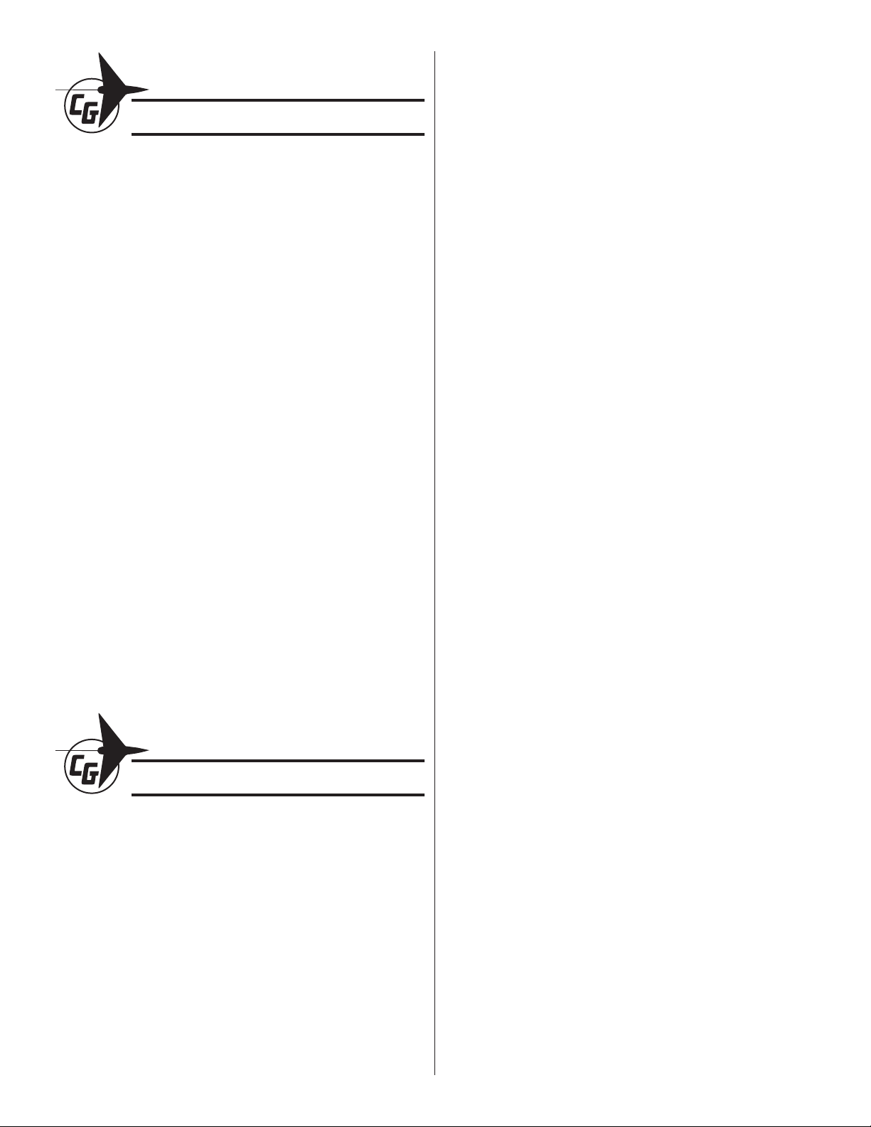
TABLE OF CONTENTS
REQUIRED ITEMS ............................................................ 2
Engine ........................................................................ 2
Radio Equipment .......................................................2
Tools & Building Supplies ........................................... 2
PREPARE FOR ASSEMBLY ............................................ 3
WING CONSTRUCTION ................................................... 3
Hinge the Ailerons ...................................................... 3
Servo & Control Horn Installation .............................. 4
Wing Dowel Installation .............................................. 6
FUSELAGE CONSTRUCTION ......................................... 6
Stabilizer & Fin Installation ......................................... 6
Flying Wires Installation ............................................. 7
Hinge the Tail Control Surfaces .................................. 9
Elevator Servo & Control Installation ......................... 9
Rudder Servo & Control Installation ......................... 11
ENGINE INSTALLATION ................................................ 13
Fit the Engine ........................................................... 13
Trim the Cowl ........................................................... 14
Throttle Pushrod & Servo Installation ......................14
RADIO INSTALLATION .................................................. 15
FUEL TANK & BATTERY INSTALLATION .....................16
Fuel Tank Assembly ................................................. 16
Mount the Fuel Tank & Battery ................................. 16
LANDING GEAR INSTALLATION .................................. 18
Main Landing Gear Installation ................................ 18
Tail Wheel Installation & Rigging .............................. 19
FINAL ASSEMBLY ......................................................... 20
Install the Cowl & Propeller ...................................... 20
Wing Installation .......................................................21
SETTING CONTROL THROWS & DIRECTION ............. 22
C.G. BALANCING ........................................................... 23
REQUIRED ITEMS
ENGINE
The Carl Goldberg Products Ultimate was designed to fl y
on the engines listed below. Using an engine outside of the
range listed is not recommended, nor can we be responsible
for any resulting damages. If you decide to use an engine
outside of this range, you must take extra precautions to
strengthen your model to handle the extra loads.
❏ 2-Stroke: .90 – 1.20 cu in [15 – 20cc]
❏ 4-Stroke: 1.20 –1.50 cu in [20 – 25cc]
In order to complete the model, you will also need a 3-1/2"
[89mm] spinner. We suggest Tru Turn’s® 3-1/2" Ultimate
aluminum spinner.
You will also need:
❏ (4) 8-32 x 1-1/4" [32mm] SHCS bolts (GPMQ3050)
❏ Fuel plug “dots” (GPMQ4166)
❏ Standard fuel clunk (DUBQ0637)
❏ A suitable Pitts-style muffl er
If you’re going to use a three line fuel tank you’ll also need a
second fuel clunk and a “fuel dot” stopper plug for the fi ll line.
RADIO EQUIPMENT
A 5-channel radio system with seven standard servos is
required for this plane. Below is a list of standard case size
servos we recommend. Note: The second elevator servo
must be reversed.
❏ (6) Futaba
size servos (FUTM0075)
®
9001 OR minimum 54 oz-in torque standard
❏ (1) Futaba 9202 (rudder servo) standard size (FUTM0090)
❏ (1) Futaba 3003 standard size servo (for throttle)
(FUTM0031)
❏ (2) Y-harnesses (FUTM4130 or FUTM4135 for
digital servos)
❏ (1) Hobbico
®
Heavy Duty Y-Harness (HCAM2751)
❏ (1) Hobbico Heavy Duty Switch Harness – Futaba J
type (HCAM2761)
❏ (4) 12" [300mm] Servo extension (HCAM2711 for Futaba)
❏ (2) 24" [610mm] Servo extension (HCAM2721 for Futaba)
TOOLS & BUILDING SUPPLIES
❏ 1/2 oz. [15g] Thin Pro
™
CA (GPMR6001)
❏ 1/2 oz. [15g] Medium Pro CA+ (GPMR6007)
❏ Denatured alcohol
❏ Drill bits: 1/16" [1.6mm], 5/64" [2mm], 3/32" [2.4mm],
5/32" [4mm], 7/32" [5.6mm]
❏ #1 Hobby knife (HCAR0105)
❏ #11 Blades (5-pack, HCAR0211)
❏ Hobbico Steel T-Pins 1" (100) (HCAR5100)
❏ Great Planes
❏ CA applicator tips (HCAR3780)
®
Pro™ Threadlocker (GPMR6060)
❏ 220-grit Sandpaper
❏ Bru Line hemostat – curved 5-1/2" (BRUR1303)
❏ Metric & standard ball-end hex drivers
❏ 36" Metal ruler (HCAR0475)
❏ 18" Flexible steel rule (HCAR0460)
❏ Builder’s Triangle Set (HCAR0480)
❏ Pliers with wire cutter (HCAR0625)
❏ Hobbico heavy duty diagonal cutter 7" (HCAR0627)
❏ Rotary tool such as Dremel
®
❏ Rotary tool reinforced cut-off wheel (GPMR8200)
❏ Masking tape (TOPR8018)
❏ Hobbico Retractable Fabric Tape Measure (HCAR0478)
❏ Pro 30-minute epoxy (GPMR6047)
❏ Pro 6-minute epoxy (GPMR6045)
❏ Robart Super Stand II (ROBP1402)
❏ Hobbico Builder’s Protractor (HCAR0490)
❏ R/C foam rubber (1/4" [6mm] – HCAQ1000)
2
Page 3
PREPARE FOR ASSEMBLY
Before you begin assembling your airplane, take the time now
to tack down the covering and get rid of any wrinkles. Areas
like servo bays, stab/fi n slots, or anywhere covering must be
trimmed should be tacked down with medium/high heat before
you trim them open. This prevents the covering from peeling
up and will make it easier to cut clean, straight lines.
❏ 2. Prepare sixteen (16) CA hinges by placing a T-pin
through the center of each hinge. Slide the hinges into the
hinge slots of each wing.
❏ 3. Fit the ailerons to each wing. Note: All ailerons are
identical with respect to shape and hinge slot location, but
you must be careful to mount left side ailerons to the left
wings and right side ailerons to the right wings because of
differences in the trim scheme.
WING CONSTRUCTION
HINGE THE AILERONS
Note: For the following steps the upper left wing is shown.
❏ 1. Use the back edge of a hobby knife to “dig out” each of the
hinge slots on both of the wings and each of the four ailerons.
❏ ❏ 4. Working with one aileron at a time, slide the edge of
each aileron all the way outboard on the wing so that the tip
of the aileron is fl ush with the tip of the wing.
❏ ❏ 5. Push the aileron tightly up against the TE of the
wing. Flex the aileron up and down a couple of times as you
push in. Now remove the T-pins.
3
Page 4
❏ ❏ 6. Hold the aileron in its full defl ected position as you’re
pushing in and apply 10 to 12 drops of thin CA to each hinge. Turn
the wing over and apply CA to the opposite side of the hinges.
❏ 7. Repeat steps 4 through 6 for the other ailerons.
SERVO & CONTROL HORN INSTALLATION
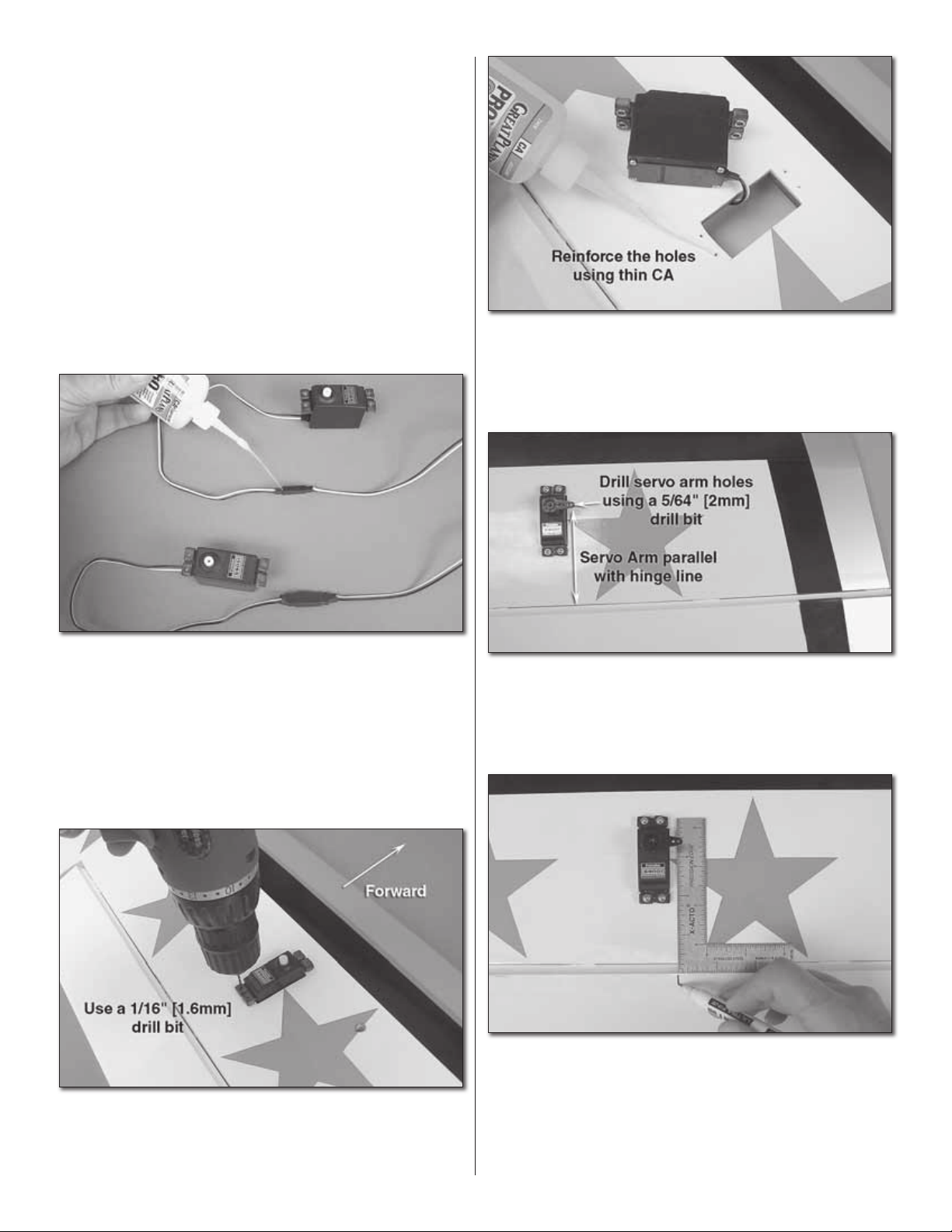
❏ 4. Use the screws that came with your servos to tap the
holes. Remove the screws and place a drop of thin CA into
each hole. This will harden the wood and will keep the screws
from loosening over time.
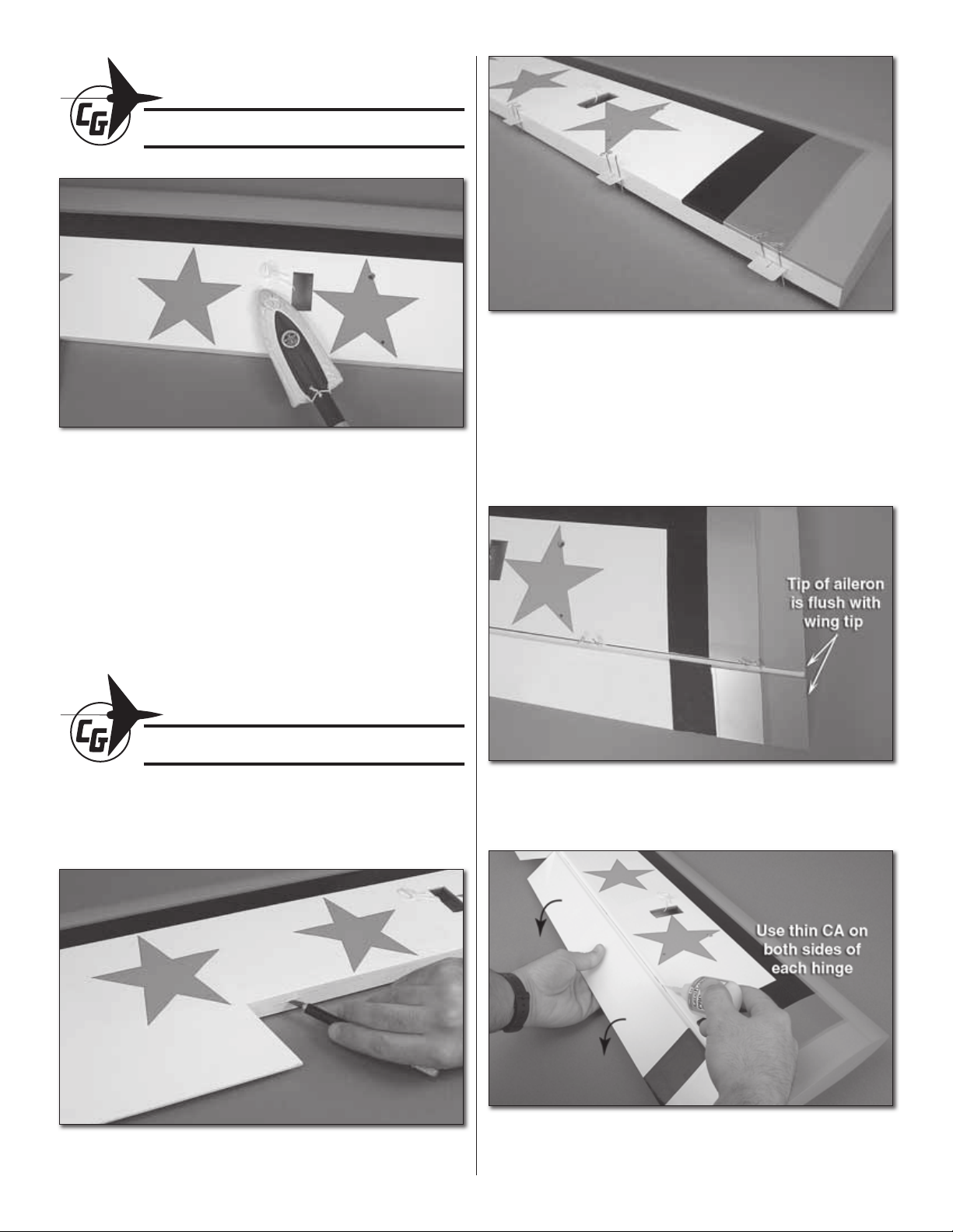
❏ 1. Gather four (4) servos and four (4) 12" [305mm] servo
extension leads. Attach a lead to each servo. To secure the
leads, use a piece of heat shrink tubing over the connection OR
place a drop of medium CA along the seam of the connection.
❏ 2. Tie a guide string to the end of each servo lead and carefully
pull the lead through the wing. You may have to move the lead
back and forth in the wing in order to clear each rib, so be careful.
Save your guide strings for the elevator servo installation.
❏ 3. Position the servos in the servo bays with the output
shaft facing forward. Using a 1/16" [1.6mm] drill bit, drill the
holes for the servo mounting screws.
❏ 5. Use your radio to center your servos and install servo
arms on each servo so that the arm that faces outboard is
90 degrees to the servo case and is parallel with the hinge
line. Drill the holes with a 5/64" [2mm] drill bit. Cut off the
remaining arms.
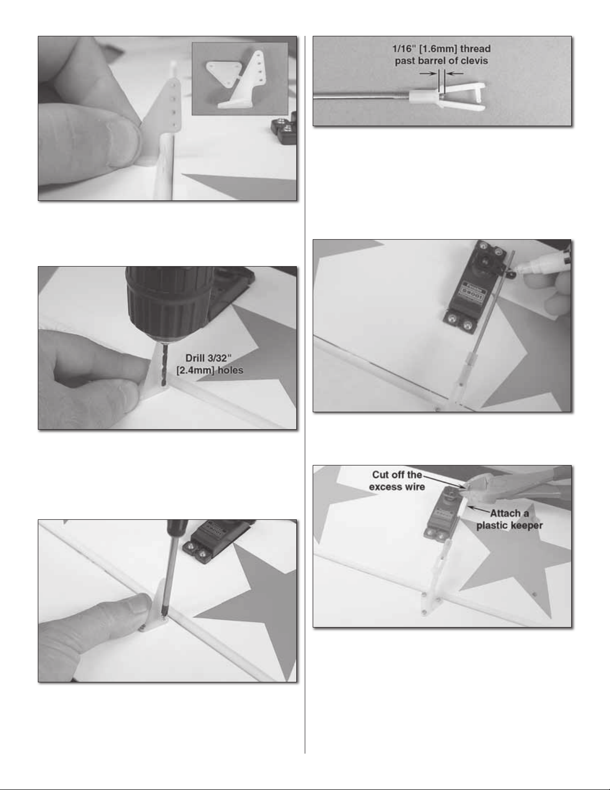
❏ 6. Use a straightedge or a builder’s square to mark the
position of the control horn centerline directly behind the third
hole out from the center of the servo. Do this for each aileron.
❏ ❏ 7. Locate four (4) control horns, four (4) backplates and
twelve (12) 2-56 x 1" [25mm] machine screws. Have your drill
ready with a 3/32" [2.4mm] drill bit.
4555
Page 5
❏ ❏ 12. Locate the four (4) 3-1/4" [83mm] long aileron
pushrods and four (4) plastic clevises. Thread the clevises
onto the pushrods so that 1/16" [1.6mm] of thread is exposed
on the inside of the threaded barrel of the clevis. Slide a
silicone clevis retainer onto the pushrod.
❏ ❏ 8. Center a control horn on the line that you made. Now
slide the horn forward or back until the pushrod holes are
aligned directly above the hinge line.
❏ ❏ 9. Use the holes in the base of the control horn as a
drilling template. Use a 3/32" [2.4mm] drill bit and drill three
holes in the aileron. Use thin CA to harden the holes that you
drilled. Note: Do not use the backing plate as a template. Its
holes must not be drilled.
❏ ❏ 13. Attach the clevis to the outermost hole of the
control horn.
❏ ❏ 14. Holding the aileron in the neutral position, extend the
pushrod to the third hole out from the center of the servo arm.
Mark the pushrod at the hole. Make a 90° bend at the mark.
❏ ❏ 10. Install the control horn and its plastic backplate with
three 2-56 x 1" [25mm] machine screws. Cut off the excess
portion of the screw when you’re done.
❏ 11. Repeat steps 7 through 10 for each aileron.
❏ ❏ 15. Install the pushrod in the third hole out from the
center of the servo arm. Attach a plastic keeper to the
pushrod and cut off the excess portion of the pushrod when
you’re done.
❏ 16. Repeat steps 12 though 15 for the remaining ailerons.
Page 6
WING DOWEL INSTALLATION
❏ 1. Locate the two 5/16" x 2" [8 x 51mm] wing dowels. Test
fi t each dowel in the LE of the pre-drilled holes of the lower
wing. To help installation in the fuselage later, you may round
the tip of each dowel using sandpaper.
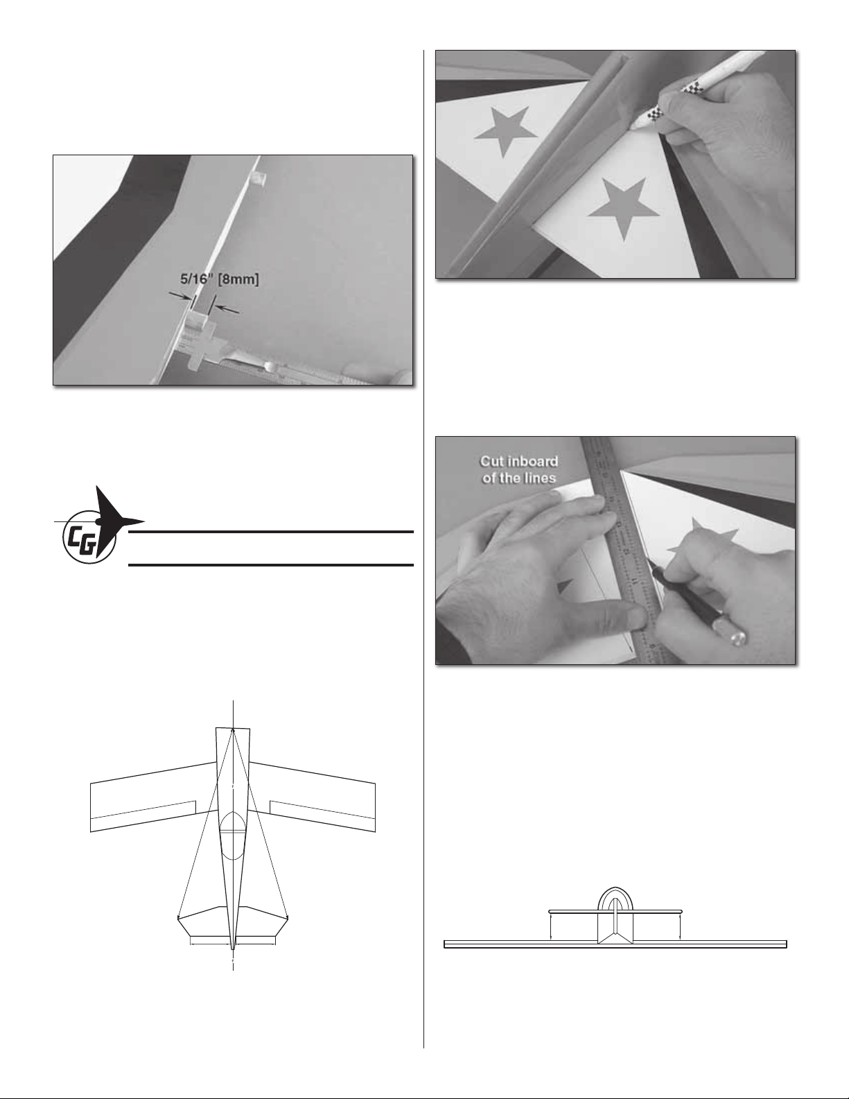
❏ 2. Glue the dowels in the wing with epoxy. Install them so
that the top of the dowels are 5/16" [8mm] from the LE of the
wing. Note: If the dowels are longer than this, they will not
allow the lower wing to seat properly.
❏ 4. Use a fi ne felt-tip pen to draw lines on the stab where
the stab meets the fuselage. Don’t forget to draw lines on
both the top and bottom of the stab.
FUSELAGE CONSTRUCTION
STABILIZER & FIN INSTALLATION
❏ 1. Temporarily fi t the bottom wing.
❏ 2. Trim the covering from the horizontal stabilizer slots in
the fuselage.
A
A=A
B=B
A
BB
❏ 5. Lay a straightedge just a bit inboard of each line you
drew. Trim the covering along the edge of the straightedge.
Be very careful not to cut into the wood fi bers – a fresh hobby
knife blade should allow you to cut the covering when light
pressure is applied.
C=C
CC
❏ 3. Slide the stab into the fuselage. Center the TE of the stab
so that the distance A=A. Make a mark at the top center of the
fi rewall and measure the distance from each stab tip. The stab
is correctly aligned when the distance A=A and B=B.
❏ 6. Slide the stab back into the fuselage and center it as
you did earlier. Level the stab so that it is parallel with the
wings. You may lightly sand the slots in the fuselage to adjust
the stab, but be careful not to make the slot too loose.
6
Page 7
❏ 7. Coat the top and bottom of the stab with 30-minute
epoxy. Fit and align the stab as you did earlier, but take note
of the trim design – the top and bottom are very similar, so
be careful to install it with the right side up.
is perpendicular to the stab. You can hold it in position with
masking tape.
❏ 12. As you’re waiting for the epoxy to cure, you can jump
ahead and build up your landing gear.
❏ 8. Use denatured alcohol applied to a paper towel to
clean up the excess epoxy. Set the fuselage aside until the
epoxy cures.
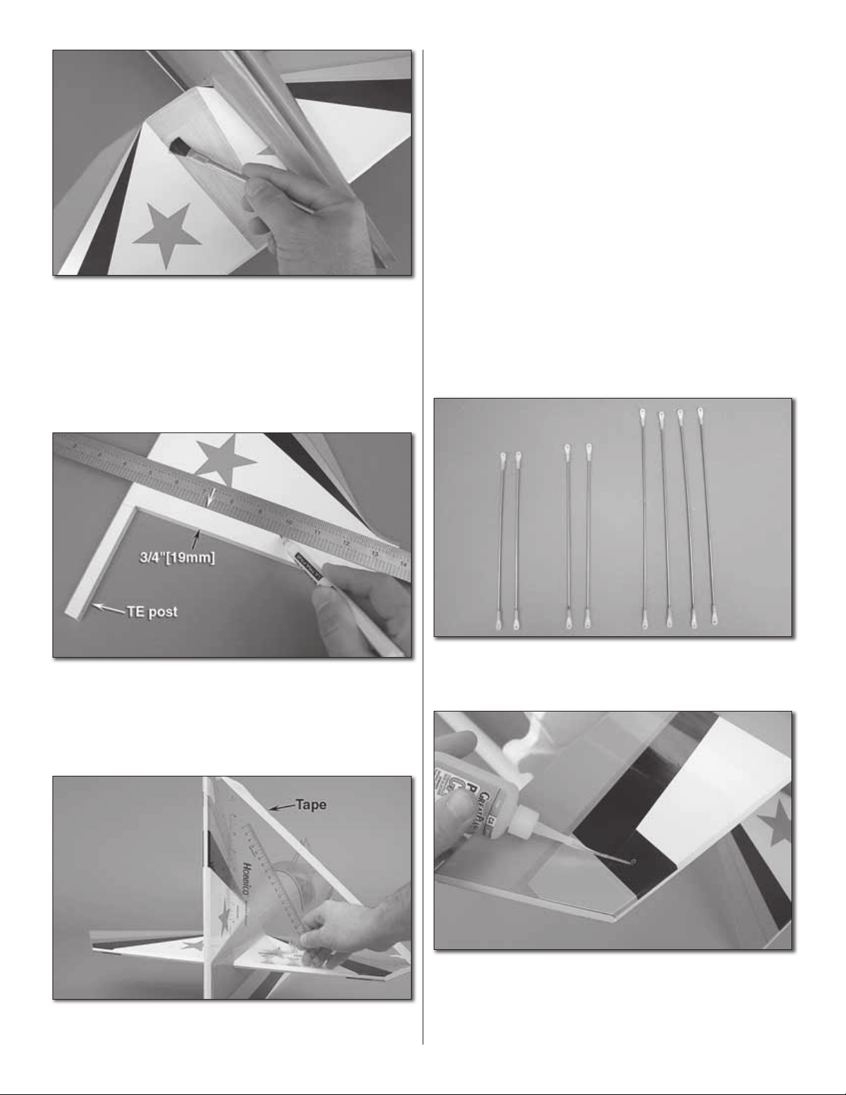
❏ 9. Lay the vertical fi n on your building table. Draw a line
that is 3/4" [19mm] above the bottom edge of the fi n and is
parallel to that edge.
❏ 10. Trim the covering from the fi n at the line you drew.
Don’t forget to trim the covering from the vertical TE post.
FLYING WIRES INSTALLATION
❏ 1. Gather two (2) 7-3/4" [197mm] fl ying wires, two 8"
[203mm] fl ying wires, and four (4) 9-3/4" [247mm] fl ying
wires. These should have a plastic fi tting at each end.
❏ 11. Apply 30-minute epoxy to the fi n and glue it into the
fuselage. Use a builder’s square to make sure that the fi n
❏ 2. Harden each of the pre-drilled holes in the fi n and the
stab with thin CA.
❏ 3. Turn the fuselage over. A foam fuselage cradle is very
helpful here.
7
Page 8
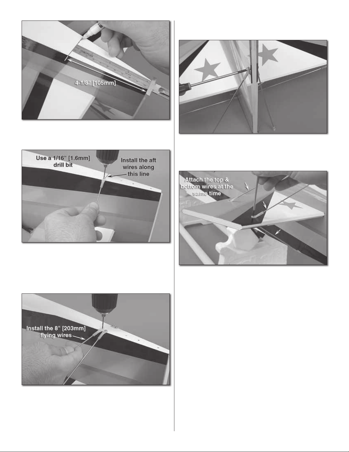
❏ 4. Measure 4-1/8" [105mm] forward from the TE of the
fuselage (the rudder hinge line) and draw a line straight
across the bottom of the fuselage.
necessarily want these to be equal lengths on both sides
– just make sure that the stab and fi n are both aligned.
❏ 8. Flip the fuselage over and use two (2) 2-56 x 5/8" [16mm]
machine screws and two (2) #2 nuts to loosely attach the
four (4) 9-3/4" [247mm] upper fl ying wires to the vertical fi n.
One screw will hold both the left and right wires.
❏ 5. Use one of the small 10mm wood screws to attach each
of the two bottom aft fl ying wires (7-3/4" [197mm] wires) to
the bottom of the fuselage. Attach them at the line you drew.
Drill a 1/16" [1.6mm] pilot hole to help you start the screw
and use thin CA to harden each hole. The other end of each
wire will attach to the aft hole in the stabilizer.
❏ 6. Using the same method, install the two 8" [203mm]
fl ying wires just ahead of the ones you just put in.
❏ 7. Adjust the length of the bottom wires until they match
the holes in the stab. Be careful to allow an equal amount
of thread engagement on each fi tting. Note: You don’t
❏ 9. Use two (2) 2-56 x 5/8" [16mm] machine screws and
#2 nuts to attach the other ends of the fl ying wires to the
left stabilizer. The corresponding top and bottom wires are
attached with one screw and a nut. Repeat this for the right
stabilizer. Apply one drop of threadlocking compound to each
of the six screws.
8
Page 9

HINGE THE TAIL CONTROL SURFACES
❏ 1. Prepare six (6) hinges and slide them into the horizontal
stabilizer.
❏ 2. Being mindful of the trim scheme, fi t the left elevator to
the left stab and the right elevator to the right stab.
❏ 7. Remove the T-pins and defl ect the rudder. Apply 10 to
12 drops of thin CA to both sides of each hinge.
❏ 8. Allow all of the hinges to air-dry. Do not use CA accelerator.
You may use CA debonder applied to a paper towel to clean
up any CA fogging or stray drops of CA on the covering.
ELEVATOR SERVO & CONTROL INSTALLATION
❏ 3. Align each elevator so that there is a 1/16" [1.6mm] gap
between the elevator counterbalance and the tip of the stab.
❏ 4. Remove the T-pins from the hinges and push the elevators
up against the stab. Fully defl ect each elevator and apply 10 to
12 drops of thin CA to the top and bottom of each hinge.
❏ 1. Trim the covering from the servo bay holes in the
fuselage sides.
❏ 5. Prepare three (3) hinges and fi t them to the vertical fi n.
Fit the rudder to the hinges.
❏ 6. Align the bottom of the rudder with the bottom of
the fuselage.
❏ 2. Install a 24" [610mm] servo extension onto each of
the elevator servos. Use heat shrink tubing to secure the
connections.
9
Page 10

❏ 3. Use the servo lead strings that you used previously for the
aileron installation to help you route your elevator servo leads.
Tie a spare nut or a servo wheel to the end of the string.
❏ 6. Center your servos and install a long servo arm onto
each elevator servo. Choose the arm that points up and is 90
degrees to the servo case. Cut off the unused arms.
❏ 7. Using a straightedge, project a line from the servo arm
to the elevator. Make a mark on the elevator for the control
horn. Do this for both elevators.
❏ 4. Route the string into the fuselage through each elevator
servo bay and route it up and over the two formers in the fuselage.
This will prevent your elevator servo leads from rubbing on or
becoming tangled with the rudder pull-pull system.
❏ 5. Install the elevator servos with the output shafts facing
forward. Use the screws that came with your servos.
❏ 8. Install the elevator control horns using six (6) 2-56 x 1"
[25mm] machine screws. Use a 5/64" [2mm] drill bit to drill
the holes.
❏ 9. Locate two (2) 6" [152mm] pushrods and two (2) plastic
clevises. Thread the clevises onto the pushrods so that 1/16"
[1.6mm] of thread is exposed on the inside of the threaded barrel
of the clevis. Slide a silicone clevis retainer onto the pushrods.
10
Page 11

❏ 10. Attach each pushrod to the outermost hole of the
elevator control horns.
❏ ❏ 11. Tape or hold the elevator in the neutral position.
Extend the pushrod to the third hole out from the center of
the servo arm. Make a 90° bend at the mark.
❏ ❏ 12. Attach a plastic keeper to the pushrod and cut off
the excess portion of the pushrod.
❏ 3. Make a mark 5/8" [16mm] from the bottom of the rudder.
Center a control horn over the mark and drill three holes.
❏ 13. Repeat steps 11 and 12 for the other elevator.
RUDDER SERVO & CONTROL INSTALLATION
❏ 4. Attach two control horns as shown using three (3)
2-56 x 1" [25mm] machine screws and three (3) #2 nuts. Use
threadlocking compound on the screw threads.
❏ 1. Install the rudder servo in the servo tray.
❏ 2. Center the servo and fi t a long, double-sided servo arm
to it.
❏ 5. Trim away the covering from the rudder cable exit
holes in the fuselage. These are located directly below the
elevator servos.
11
Page 12

❏ 6. Locate two (2) 36" [915mm] control cables, four (4) threaded
cable couplers, four (4) crimp tubes, and four (4) clevises.
❏ 7. Thread a clevis onto each of the four threaded cable
couplers. Thread it on far enough so that the coupler threads
are 1/16" [1.6mm] past the barrel of the clevis.
former directly ahead of the cable exit holes. Be sure to route
the cable through the hole in the former.
❏ 11. Visually inspect the cable routing. Make sure that your
rudder cables will not interfere or become tangled in the
elevator servo leads.
❏ 12. Tape a straightedge to the side of the fi n and rudder to
hold the rudder straight.
❏ 13. Center your rudder servo. Note: It may be helpful to
leave your radio “ON” during the rigging procedure to ensure
that the rudder servo will remain straight.
❏ 8. Prepare one end of each cable as shown. Fold at least
1" [25mm] of cable over and crimp it tightly using your pliers.
DO NOT crimp the other end of the cable yet. You will need
to custom fi t it later.
❏ 9. Visually inspect the crimps that you just made. Check
to see that the wires are fi rmly crimped in place. Inspect any
further crimps that you must make in the same manner
❏ ❏ 14. Extend the other end of the rudder cable into the
fuselage. Assemble the cable couplers and adjust the length
of the rudder cable as close as you can. Crimp the cable.
Don’t worry too much about getting the cable length perfect.
You can still adjust the cables using the threaded clevises.
❏ 15. Repeat the last step for the other cable.
❏ 10. Attach a control cable to the outermost hole of one
rudder control horn and route it into the fuselage. There is a
12
Page 13

ENGINE INSTALLATION
FIT THE ENGINE
❏ 1. Fit the engine to your engine mount so that the drive
washer of the engine is 5-7/8" [149mm] from the base of the
mount (fi rewall). Use a minimum of 8-32 bolts to attach the
engine to the mount (these are not supplied with the kit). Drill
and tap your mount.
❏ 5. Drill four 7/32" [5.6mm] holes for the engine mount
bolts. Drill a 5/32" [4mm] hole for the throttle pushrod while
you’re at it. If you’re going to use a three line fuel tank setup,
go ahead and drill a third hole now. Use a 7/32" [5.6mm] drill
bit for this.
❏ 2. Make index marks between the two sliding rails. This
will help you note the position of the rails for the next step.
❏ 3. Remove the engine from the mount, keeping the two
sides of the mount together.
❏ 4. Center the engine mount over the cross-hairs etched
into the fi rewall. Be careful to note the position of the mount
so that the cylinder head is oriented on the proper side of the
fuselage. Mark the location for the engine mount bolts and
where you will need to drill the hole for the throttle pushrod.
❏ 6. Locate the four (4) 8-32 x 1" [25mm] engine mount bolts
and their associated 8-32 blind nuts. Press the blind nuts into
the back side of the fi rewall. You can use the bolts to help you
pull the blind nuts into position.
❏ 7. Bolt the engine and the engine mount to the fi rewall.
Temporarily attach the muffl er.
13
13
Page 14

TRIM THE COWL
❏ 1. Tape a 4" x 13" [102 x 330mm] piece of card stock to the
fuselage so that it lays over the cylinder head. Tape a 6" x 11"
[152 x 280mm] piece of card stock to the fuselage bottom so
that it is positioned over the muffl er. You may also need to
make a template for your mixture control valves.
❏ 5. Trace around the openings in the templates you made.
Use a Dremel tool to cut a hole in the cowl for the cylinder
head, muffl er, and needle valves. Fit the engine and muffl er
and re-trim where necessary.
❏ 6. Remove the cowl and set it aside.
❏ 2. Trim a hole in the card stock to accommodate your
engine’s cylinder head, muffl er, and mixture control valves.
Trim a little and then check your progress by laying the
templates over the engine. When you’re satisfi ed, leave the
templates attached where they are. You’ll be fi tting the cowl
next, so the engine will be removed. The templates will help
you transfer your engine’s exact location to the outside of
the cowl.
❏ 3. Remove the engine and engine mount and set them
aside. If your engine does not interfere with the cowl, you may
leave it attached. We left the engine attached and removed
the muffl er.
THROTTLE PUSHROD & SERVO INSTALLATION
❏ 1. Install your engine and engine mount using threadlocking
compound with the four (4) 8-32 x 1" [25mm] engine mount
bolts and four (4) #8 washers.
❏ 2. Locate the 20" [508mm] throttle pushrod, the throttle
pushrod tube, one threaded clevis, and one silicone clevis
retainer. Thread the clevis on so that at least 1/16" [1.6mm] is
threaded past the inside end of the barrel of the clevis.
❏ 4. Use the six (6) 1/2" [13mm] button head screws to
attach the cowl.
❏ 3. Fit the pushrod tube into the hole that you drilled earlier
and slide the pushrod into the tube. Attach the clevis to the
throttle arm. Bend the pushrod around any obstructions.
14
14
Page 15

❏ 4. Install the throttle servo.
RADIO INSTALLATION
❏ 1. Install a new radio switch in the right side of the fuselage.
There is a cutout for a switch there. Optionally you can install
a switch and charge jack, but you will need to mount it up
higher along the same former. You can also mount it to the
opposite side. The Great Planes Switch and Charge Jack
Mounting Set (GPMM1000) is a good choice because of its
thin profi le.
❏ 5. Prepare a servo arm or a servo wheel and install a
screw-lock pushrod connector. Use a plastic retainer to
secure the connector to the servo arm.
❏ 6. Fit the muffl er and any extension that you may need for
the main mixture control valve.
❏ 2. Install a heavy duty Y-harness to the upper cabane struts
using small tie wraps to secure each lead of the harness to
the cabane struts. Note: We chose a heavy duty harness for
this application because of the long leads.
15
Page 16

❏ 3. Connect your servo leads and the battery switch lead to
the receiver. Connect a Y-harness to your aileron channel. Wrap
the receiver in latex foam rubber and install it in the fuselage.
❏ 4. Route the receiver’s antenna lead through the antenna
tube as shown. Make sure that your antenna is fully extended.
FUEL TANK & BATTERY
INSTALLATION
FUEL TANK ASSEMBLY
❏ 2. Assemble the stopper as shown with the vent line
pointing up to the top of the tank. The top of the tank must be
one of the wide sides so that the tank lays down as fl at to the
tray as possible. Make sure that the clunk is spaced at least
1/4" [6mm] from the back of the fuel tank – this will prevent it
from hanging up when the airplane fl ies inverted. Note: We
elected to use the three line setup, so there are two clunks
(only one is supplied with this kit).
❏ 3. Label your vent, fi ll, and carb lines coming out of the
tank and install the stopper onto the tank. Do not overtighten
the stopper: this can cause the tank to split. Draw an arrow
on the back of the tank so you can easily tell which side is
up (vent).
MOUNT THE FUEL TANK & BATTERY
You may want to wait until your model is ready to balance to
perform this section. The 1.20 two-stroke that we installed in
this manual required a few ounces of ballast weight to arrive
at the proper C.G. with the battery installed on the fuel tank
tray as shown in the next steps. Installing a 1.20 four-stroke
without using lead ballast required the battery to be moved
to the bay just behind the fuel tank.
❏ 1. Gather the parts required for the fuel tank. You will
need: one (1) plastic fuel tank, one (1) rubber stopper, one
(1) stopper washer, one (1) stopper nut, one (1) stopper
screw, three (3) aluminum fuel lines, and one clunk. If you
are going to use a three line tank, you will need to purchase
a third fuel clunk and some extra fuel tubing.
❏ 1. Wrap your fuel tank and radio battery in latex foam
rubber. Use a minimum of 1/4" [6mm] thick foam. Locate the
fuel tank tray.
16
Page 17

❏ 2. Use one large tie wrap to attach your battery to the fuel
tank tray. Note: You may need to drill a few holes in the tray
in order to mount your battery securely.
❏ 6. Use the 6" [152mm] stick to support the fuel tank. Push
the tank tray forward until it is locked into the fi rewall cutouts.
Epoxy the stick to the former and the tray. Use the supplied
blocks to increase the gluing area on the former.
❏ 3. Use two large plastic tie wraps to secure your tank
and battery to the fuel tank tray. Note: The two tabs face
forward. Make sure you install the vent side of the tank up
(away from the tray).
❏ 4. Install silicone fuel lines to the tank.
❏ 5. Fit the tank and tray assembly into the fuselage. The
fuel tank tray tabs fi t into the semi-circular cutouts on the
back side of the fi rewall. Make sure that the tank points up
and that the fuel lines are routed through the fi rewall without
any kinks.
❏ 7. Attach your fuel lines.
❏ 8. Connect the battery to the radio switch. Use heat
shrink tubing to ensure that the battery will not become
disconnected.
17
Page 18

LANDING GEAR INSTALLATION
MAIN LANDING GEAR INSTALLATION
❏ 1. Collect the following parts: One (1) landing gear strap,
two (2) wheel pants, two (2) 3-1/4" [83mm] axles, two (2)
self-locking axle nuts, four (4) wheel collars, four (4) 4-40 x
1/2" [13mm] screws, and four (4) 4-40 blind nuts.
❏ 4. Remove the wheel collars and fi le fl at spots on the
bottom side of each axle.
❏ 2. Install the axles onto the landing gear strap using the
self-locking axle nuts.
❏ 3. Position a wheel collar on each axle so that there is a
1/16" [2mm] gap between the wheel collar and the base of
the axle. Fit the wheel and the outer wheel collar.
❏ 5. Install each wheel using an inner and an outer wheel
collar. Apply threadlocking compound to the threads of each
wheel collar’s locking screw. Note: The shouldered portion
of each wheel collar should face the wheel.
❏ 6. Cut a 5/16" [8mm] wide slot in each of the wheel pants
in the location shown.
18
Page 19

❏ 7. Install two 4-40 blind nuts in each wheel pant from
the inside.
TAIL WHEEL INSTALLATION & RIGGING
❏ 1. Collect the following parts: One (1) tail wheel landing
gear strap, one (1) tail wheel wire, one (1) 1-1/4" [32mm] tail
wheel, one (1) steering arm assembly, one (1) large area
wheel collar, one (1) standard collar, two (2) springs, and two
(2) 4-40 x 1/2" [13mm] screws.
❏ 8. Install each wheel pant using the four (4) 4-40 x 1/2"
[13mm] screws and some threadlocking compound. Note
the direction of the landing gear strap – the swept edge of
the gear faces forward.
❏ 9. Use three (3) 8-32 x 3/4" [19mm] bolts and three #8
washers to attach the landing gear to the fuselage. Use
threadlocking compound on the bolt threads.
❏ 10. Apply a couple drops of light machine oil to the axles
and check them for free rotation.
❏ 2. Install the large area wheel collar onto the tail wheel
wire as shown.
❏ 3. Fit the tail wheel wire onto the landing gear strap using
the steering arm assembly on the top side. Position the
steering arm collar so that the threaded arms are parallel
with the axle. Remove the steering arm collar and fi le a fl at
spot in the tail wheel wire in that position. Install the wire to
the landing gear strap using threadlocking compound on all
screw threads.
19
Page 20

❏ 4. Rotate the threaded joints until the center hole of the
joint is approximately 1" [25mm] from the center of the tail
wheel wire. Make each side equal. Note: You may want to
adjust these later to get the tail wheel steering throw that
better suits you.
❏ 5. Fit the 1-1/4" [32mm] tail wheel and attach it using the
standard wheel collar. File a fl at spot in the axle for the collar
and use threadlocking compound on the locking screw.
❏ 8. Install the tail wheel springs onto the tail wheel steering
arms and connect them to the rudder control horns as
shown. Bend the wire of the spring back onto itself and twist
the ends of it around the wire. Cut off any excess wire.
❏ 9. Test the operation of the tail wheel using your radio.
❏ 10. Apply a couple drops of light machine oil to the axle.
FINAL ASSEMBLY
INSTALL THE COWL & PROPELLER
❏ 1. Install all engine accessories like the muffl er, needle
valve extension, throttle pushrod, and all fuel lines. If you
didn’t apply threadlocking compound to the engine mounting
bolts, do so now. Check all mounting bolts for proper torque.
Turn on your radio and do one fi nal check to see that your
throttle is rigged properly. Set your idle position per the
engine manufacturer’s specifi cation.
❏ 6. Use the two (2) 4-40 x 1/2" [13mm] screws to attach the
tail wheel landing gear to the fuselage. Apply threadlocking
compound to the threads.
❏ 7. Turn your radio “ON” and center your rudder. Leave the
radio on or lock the rudder in position while you set your tail
wheel adjustment.
❏ 2. Use some denatured alcohol to clean off any marks you
made while trimming the cowl. Use the six (6) 1/2" [13mm]
button head screws to attach the cowl.
❏ 3. Attach a 3-1/2" [89mm] spinner (not supplied) and a
suitable propeller. Always balance your propeller (and spare
props) using a prop balancer.
20
Page 21

WING INSTALLATION
❏ 1. Set your lower wing in position over the fuselage
and tuck the extensions into the fuselage. Locate the wing
reinforcement plate and the plastic wing bolts. Bolt the wing
on with the reinforcement plate in position.
layer of 30-minute epoxy to the bottom of the reinforcement
plate and set it in place. Glue the reinforcement plate in place
by lightly snugging down the wing bolts. As a precaution,
you can loosen and re-tighten the wing bolts in 15 minute
intervals until the epoxy sets.
❏ 2. Trace the outline of the reinforcement plate onto the
lower wing.
❏ 3. Remove the wing and trim the covering 1/8" [3.2mm]
inside the line you traced. Peel off the covering so that the wood
is exposed.
❏ 4. Lubricate the threads of the wing bolts with petroleum
jelly. This will keep them from being glued in place in the next
step. Mix up some 30-minute epoxy and thin it down with
several drops of denatured alcohol.
❏ 6. Locate the two (2) interplane wing struts, two (2)
4-40 x 3/4" [19mm] bolts, two (2) 4-40 self-locking nuts, and
two (2) #4 washers.
❏ 7. Identify the top front of each wing strut – look for the
small lightening hole behind the covering. You may want to
mark these with a felt-tip pen.
❏ 5. Set the wing back in position and connect your aileron
servo leads in anticipation of the next section. Apply a thin
❏ 8. Install the interplane struts to the bottom wing fi nger-tight.
21
Page 22

❏ 9. Set the top wing in position and thread the interplane
struts into the top wing fi nger-tight.
SETTING CONTROL THROWS
& DIRECTION
❏ 1. Turn your radio on and neutralize all of your trims.
Check to see that your controls are operating in the correct
direction by standing behind the model and moving the sticks.
Reverse any servos using the servo reversing switches on
your radio.
❏ 10. Bolt the top wing to the cabane struts using the two (2)
4-40 x 3/4" [19mm] bolts, two (2) 4-40 self-locking nuts, and
two (2) #4 washers. Place the washers under the bolt heads.
❏ 11. Connect your upper wing servo wires.
❏ 2. Neutralize (center) all control surfaces by adjusting the
pushrod lengths at the clevises. Install the silicone retainers
and check for free travel of each control surface.
❏ 3. Pre-tension your rudder’s pull-pull cable system by
adjusting the clevises at the rudder. Keep the servo centered
22
Page 23

and adjust the tension of both cables evenly. Tension the
cables until there is no slack in the cables when you apply
light pressure to the rudder with the servo fi xed. Make sure
that the rudder itself is still centered once you have the
proper tension set. You should periodically inspect the pullpull system for proper tension and general condition.
❏ 4. Set all of your control throws according to the chart
below. If your radio does not have dual rates, we recommend
starting out on the low rates for the fi rst few fl ights and then
moving up to the high rates. Use a builder’s protractor or an
inclinometer to help you achieve the proper throws.
C.G. BALANCING
Setting up your airplane with the proper C.G. and setting
proper control throws are the most important things you
can do to ensure that your airplane is safe. An airplane with
improper C.G. and/or throws is unstable and can potentially
be impossible to control. IMPORTANT: Never neglect these
procedures with any airplane! Take the time to properly
balance and setup your model!
Set your throws mechanically by repositioning the linkages
in the servo arms and/or the control horns and THEN
fi ne-tune them with your transmitter’s end-point feature.
Settings:
High Rate Low Rate
ELEVATOR: 14° up 12° up
14° down 12° down
RUDDER: 23° right 15° right
23° left 15° left
AILERONS: 12° up 10° up
12° down 10° down
❏ 1. Measure 2-3/8" [60mm] back from the LE of the lower
wing and make a mark. This will be where your model will
need to balance. The forward C.G. limit is 1-7/8" [48mm] from
the lower wing’s LE. The aft C.G. limit is 2-7/8" [73mm] from
the lower wing’s LE. You may move your radio gear to help
your plane balance, but make sure that it is secured properly.
❏ 2. Turn your model over and balance it on a suitable stand or
using your fi ngertips. Use the stabilizer as your zero reference.
23
Page 24

Date Built:
Date of First Flight:
Flight Notes:
FLIGHT LOG
 Loading...