

Page 1
1
INSTRUCTIONS
WARNING
A radio-controlled model is not a toy and is not intended for persons under 16 years old. Keep
this kit out of the reach of younger children, as it contains parts that could be dangerous. A radiocontrolled model is capable of causing serious bodily injury and property damage. It is the buyer's
responsibility to assemble this aircraft correctly and to properly install the motor, radio, and all other
equipment. Test and fly the finished model only in the presence and with the assistance of another
experienced R/C flyer. The model must always be operated and flown using great care and common
sense, as well as in accordance with the Safety Code of the Academy of Model Aeronautics
(www.modelaircraft.org). We suggest you join the AMA and become properly insured prior to flying
this model. Also, consult with the AMA or your local hobby dealer to find an experienced instructor in
your area. Per the Federal Communications Commission, you are required to use only those radio frequencies specified "for Model Aircraft."
LIMITED WARRANTY
Carl Goldberg Products has inspected and certified the components of this aircraft. The company urges the buyer to perform his
own inspection, prior to assembly, and to immediately request a replacement of any parts he believes to be defective for their
intended use. The company warrants replacement of any such components, provided the buyer requests such replacement within a period of 90 days from the date of purchase and provided the defective part is returned, if so requested by the company.
No other warranty, expressed or implied, is made by the company with respect to this kit. The buyer acknowledges and understands that it is his responsibility to carefully assemble the finished flying model airplane and to fly it safely. The buyer hereby
assumes full responsibility for the risk and all liability for personal or property damage or injury arising out of the buyer's use of the
components of this kit.
CARL GOLDBERG PRODUCTS, LTD.
P.O. Box 818 Oakwood GA 30566 Phone #678-450-0085 Fax # 770-532-2163 www.carlgoldbergproducts.com
© Copyright 2005 Carl Goldberg Products LTD
TM
77” Edge 540 ARF
Page 2

2
Congratulations on your purchase of the 77”
Edge 540 ARF. Every effort has been made to
produce a lightweight, straight, easy to assemble aircraft. Because of its oversize control surfaces which are double beveled to allow for
extreme throws, great care must be taken in the
set-up and flying of this airplane. Quality hardware components have been provided to allow
for 3D set-up while maintaining adequate
mechanical advantage to eliminate flutter. It is
your responsibility as an advanced pilot to fly
the aircraft in an intelligent manner. THROTTLE
MANAGEMENT IS A MUST!!!!!!! Carl
Goldberg Products has flown the 77” Edge
540 ARF through a very rigorous flight-testing
schedule and have stressed the airframe
beyond all practical parameters without a single
failure. Carl Goldberg Products will NOT
warranty the 77” Edge 540 ARF against flutter due
to improper set-up or excessive speed maneuvers. having said that, we believe you will find
the 77” Edge 540 ARF to be one of the most
responsive, in-the-grove aircraft on the market.
Just remember to use common sense when flying this high performance machine.
We are very proud of the construction of the 77”
Edge 540 ARF and all of our other ARF aircraft.
Each aircraft is jig built to insure a straight true
airframe. Every effort is made to build as light an
aircraft as possible. As with any professional
builder, glue is used sparingly. Please take a
moment during assembly and run a bead of
CA or aliphatic resin into the high stress
joints that you can reach such as the landing
gear plate, servo mounting trays, wing hold
down blocks, Firewall, etc. Also, during the
course of shipping from the manufacturer to our
facility in the United States, it is not uncommon
for the aircraft to experience several changes in
climate. This may cause the iron-on covering to
develop wrinkles. This is not a fault of the manufacturer. Please take a few minutes with your
heating iron and heat gun to iron down the
seams and re-shrink the covering where needed.
The results will be a beautiful aircraft with a
breathtaking finish that you will be proud to display at your flying club.
Before beginning assembly of your 77” Edge
540 ARF, we highly recommend that you study
this manual in its entirety. You should begin
planning your radio installation based on your
choice of engine and equipment from the beginning.
Because the 77” Edge 540 ARF is intended
for those with some degree of modeling
experience, every minute detail will not be
covered. This is not a basic trainer.
Assembly of this aircraft will be easy for the
experienced modeler, and by following the
instructions within this manual and using
the skills you’ve gained during your modeling career you will be able to produce a first
class aircraft.
Building supplies needed
Hobby knife w/#11 blades
Thin CA
Medium CA
Canopy glue
30 minute epoxy
Thread lock
Diagonal wire cutters
Pliers
Assorted drill bits
Various sized screwdrivers( both Phillips and
standard head)
Tape measure
Dry-erase marker
Paper towels
Rubbing alcohol
Electrical tape
4-40 Tap & Die Set
3/32, 7/64, 9/64 & 3mm Allen wrench
Wax Paper
3-1 Oil
Note:
Thread lock must be used where
ever any machine bolts are threading
into any type of nuts. If you do not
use thread lock the bolts could
become loose and fall out in flight.
Page 3

3
ADHESIVES & GLUING TECHNIQUES
CA adhesives are specially formulated to firmly glue the
plywood, hardwood, and balsa used in your model and to
withstand the vibration and stresses of high performance
flight. However, there are times, such as when you are
installing the stabilizer and fin on the fuselage and want
more set-up time for careful alignment and positioning,
then you should use epoxy. Occasionally, you also will
want to use thin CA, which "wicks" into the surrounding
areas. Aliphatic resin glue or similar water-based glues can
also be used, but they will add to the assembly time
because they dry so much more slowly than CA glue.
Remember, when ever using any CA, you must be careful
to read instructions thoroughly, as you will have only seconds for positioning of parts. Be sure to trial fit parts
together before gluing. Also, never use watery THIN type
CA glue for gluing plywood and hardwood parts. Thin CA's
do not adequately bond these areas.
CAUTION
Some people may experience an allergic reaction when
exposed to fumes from CA glue or epoxy. As with paints,
thinners, and solvents, it is always important to use glues
only where there is adequate ventilation to carry fumes
away. A fan is recommended. Also, special care must be
taken when using CA, as it will bond skin as well as other
surfaces. Before using any CA, carefully read all label precautions. When using CA, protective eye-wear and care in
keeping the glue away from the face is highly recommended. If CA does happen to get into the eye, hold lid open
and flush with water only. Seek immediate medical attention.
CONSTRUCTION TIPS
IMPORTANT: ALWAYS READ A FEW STEPS AHEAD.
This will alert you to coming instructions and will help you
plan accordingly.
COVERING
The 77” Edge 540 ARF is covered in a premium polyester
film chosen by many of the world's top flyers for its beauty, toughness, and ease of application and repair. It is not
uncommon for ARF's to develop a few wrinkles in transit.
If this is true of your model, the situation is easily corrected. Before you begin putting the pieces together, run
around the edge of the seams first then over the surface
of each section with an iron (either specially designed for
airplane use or the more cumbersome household iron).
Apply the heat (set at about 350° F), following along with
a soft cloth and pressing down on the covering as you go
around. This will more firmly set the covering adhesive
into the wood and keep your aircraft covering tight and
smooth in the future. Once you have ironed the seams
stay away from them with the heat or the covering will
slide when you try to shrink the middle. If this happens the
wrinkles will not come out of the covering.
ITEMS NEEDED TO COMPLETE THIS AIRCRAFT
24” FUEL LINE
ENGINE ..1.2O TO 2.4
1 RADIO GUIDANCE SYSTEM
2 12” AILERON SERVO EXTENSION WIRES
3 11” SERVO Y-CONNECTORS
1 CA ACCELERATOR
1 2 OZ. BOTTLE CA MEDIUM GLUE
1 1/2 OZ. BOTTLE CA THIN GLUE
1 30 MINUET EPOXY
1 1/2” FOAM RUBBER
1 3-1/2” SPINNER
OPTIONAL:
1 PILOT FIGURE
SERVO ARM EXTENSIONS
NOTE: The 77” Edge 540 ARF covering closely
matches Ultra Coat:
Bright Yellow #872
True Red #866
Sliver #881
Black #874
Page 4
3. Using a 1/8” drill, drill half way through the
aileron hole from both top and bottom till the
drill passes through the aileron.
Insert the 6-32 x 3” bolt into the top of the
aileron.
Thread the bolt all the way till the head is flush
with the top of the aileron.
4.
On the bottom of the aileron, place first the
cup washer then the nylon nut onto the 6-32
bolt.
Using a screwdriver tighten the nylon nut all
the way down till it rest in the cup washer and
is tight to the aileron.
Thread the nylon adjustable control horn onto
the bolt.(Note: Thread the side that you can
see the cut threads in the nylon onto the
bolt)
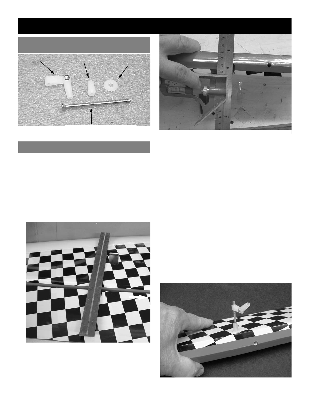
2. With the aileron servo in place, make a mark
on the aileron at a 90º degree angle to the
trailing edge and in line with the servo. Look
for the control horn hard point under the covering. This is the location for the control horn.
4
AILERON CONTROL HORN INSTALLATION
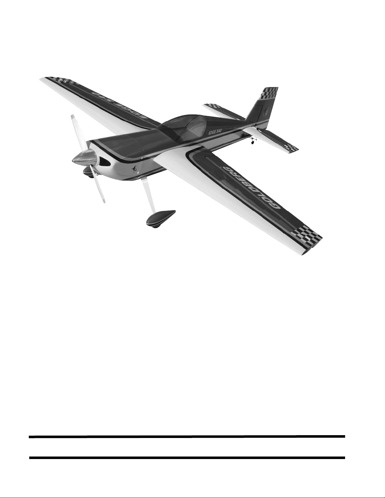
1. Collect the following items
(4) 4-40 x 3” socket head bolt
(4) Nylon Adjustable Control horns
(4) Nylon Nut
(4) Nylon Cup Washer
CONTROL HORN PART NAMES
WING ASSEMBLY
6-32 x 3” bolt
adjustable control
horn
nut
washer
Transfer the mark from the bottom of the
aileron to the top side.
Page 5
5
2. Trial fit the hinges into the holes on both the
aileron and wing.
If necessary use a 7/32” drill in each hole 1/8”
deep to allow the shoulder of the hinge to go in
Make sure all hinges insert half way.
3. Place 1 drop of oil on each of the hinge joints
at the center. This is to keep the hinges loose
and prevent epoxy from sticking at the joint.
Caution: Do not get any oil on the length of the
hinge or it will not glue into the surface.
AILERON INSTALLATION
1. Collect the following parts:
(1) Left wing
(1) Right wing
(1) Left aileron
(1) Right aileron
(10) hinges
(2) 1/4-20 nylon wing bolts
4. Select the aileron for the wing half on which
you are working.
Mix up a liberal amount of 30 minute epoxy.
Using a piece of wire or a toothpick, work
some epoxy into each hole on the wing and
aileron.
Working with 1 hinge at a time, place a dab of
epoxy and insert the hinge half way into one of
the aileron holes.
Repeat for each of the other hinges for that
aileron.
5.
Working quickly, place some epoxy on the
second half of each hinge and insert the
aileron into the wing.
Slide the aileron toward the wing until no gap
remains between the aileron and the wing.
When satisfied with the alignment, flex the
aileron up and down to confirm that the hinges
are working freely. remove any excess epoxy.
Apply a few strips of masking tape to keep the
pieces in place.
Allow to dry before flexing the aileron.
6.
Repeat the above steps for the other half of
the wing.
AILERON SERVO INSTALLATION
1. Collect the following parts:
(1) Left wing
(1) Right wing
(4) Servos
(2) Servo “Y” Harness
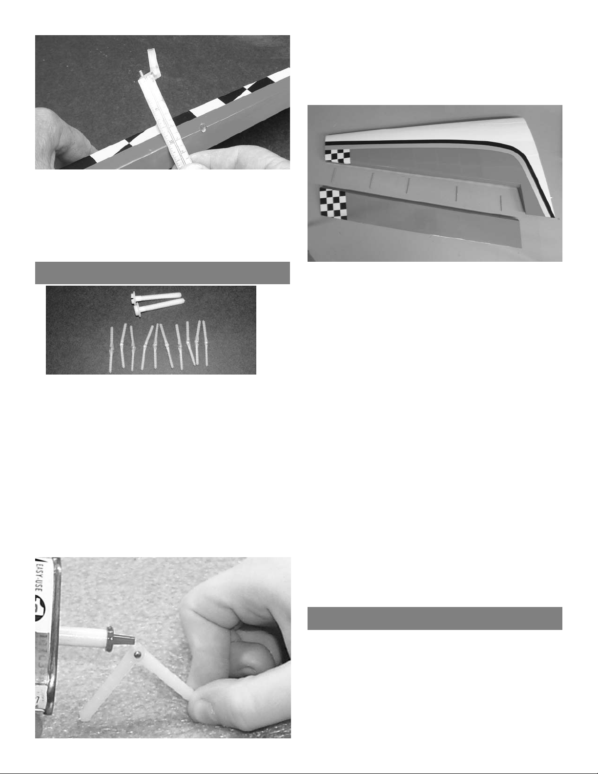
5. It is important when two servos are to the
same aileron that both control horns are equal
length.
Measure from the center of the hinge line to
the top of the nylon control horn bracket and
adjust both to be equal.
Page 6
6
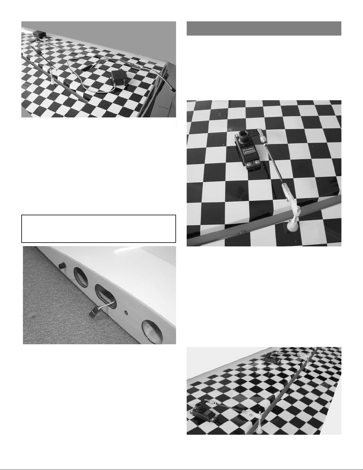
2. Attach the outboard servo to one side of the
Y-connector. Insert the Y-connector into the
outboard hole and guide down the wing to the
inboard servo hole. Pull the other side of the
y-connector through the hole and connect the
other servo. Continue pulling the y-connector
to the center of the wing.
Screw the two servos into place with the out-
put arms forward, using the hardware supplied with the radio.
IMPORTANT! To ensure that any connections locat-
ed inside the wing will not come loose, either when
the wires are pulled, or during flying, always tape
them securely together with electrical tape.
3. Tape the end of the plug to the root rib.
Repeat for the other wing half.
Aileron Servos Pushrods
1. COLLECT THE FOLLOWING ITEMS:
(4) 4-40 X 3-1/8” PUSHRODS THREADED
BOTH ENDS
(4) 4-40 CLEVIS
(4) SILICONE CLEVIS RETAINERS
(4) 4-40 nuts
3. Repeat for the other three servos
2. Screw the 4-40 x 3-1/8” pushrod into the nylon
control horn fitting on the aileron.
Slide the silicone clevis retainer over the end
of the clevis.
Screw the nut then the clevis on the other end
of the pushrod.
Center the servo with the radio, make sure the
aileron is centered and adjust the clevis to fit
on the servo output arm.
After final adjustment, tighten nut against cle-
vis and put thread lock on nut.
Page 7
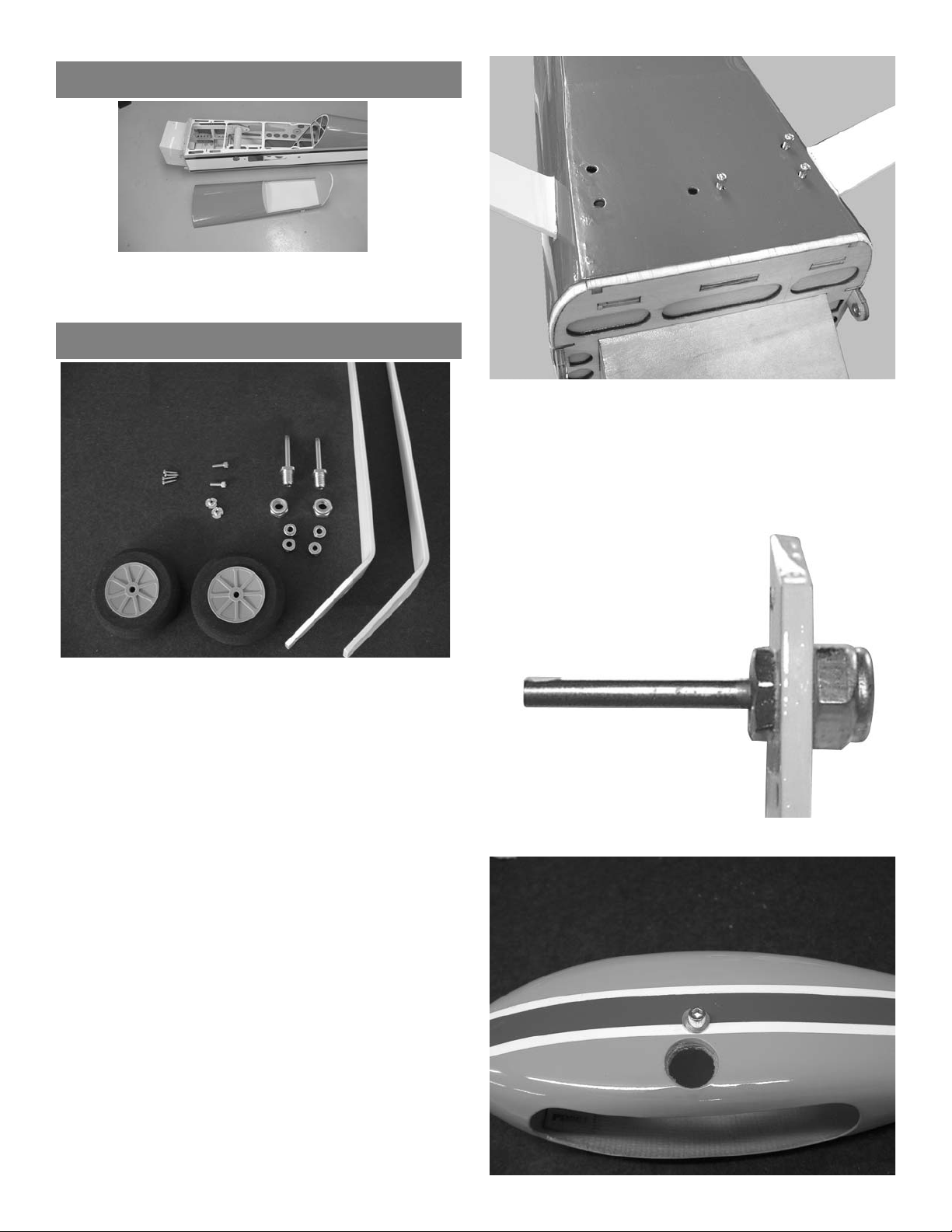
WHEEL AND WHEEL PANTS
1. Collect the following items:
(2) 5-32 x 1-1/4” Axle with Locking Nut
(4) 5/32 Wheel Collars
(6) 6-32 x 1” Cap Screws
(2) 4-40 Blind Nuts
(2) 4-40 x 1/2” Button Head Screws
(2) 3-1/4” Wheels
(2) Landing gear legs
3. Mount the axle to the landing gears.
7
FUSELAGE HATCH
The top front half of the fuselage is a hatch. Remove
the 4-40 socket head bolts on the side of the fuselage to disengage the hatch.
2. Insert the gear legs through the slots in the
fuselage side.
Use the six 6-32 x 1” bolts to secure the gear.
The blind nuts are already installed in the
fuselage.
Be sure and use thread lock on the bolts.
Page 8

8
4. Install the blind nut in the wheel pant using the
4-40 bolt to pull it into the hole.
Wheel Collars
Wheel Pant
Wheel
Landing Gear
5. Mount the wheel pant on the landing gear
along with the wheel collars and wheels.
Center the wheel on the axle.
Use the 4-40 x 1/2” bolt to hold the wheel pant
to the gear. Be sure to use lock-lock on the
bolts.
HINGING RUDDER
1. Locate the rudder and four hinges
Trial fit the hinges to make sure they all go up
to the hinge pin in rudder and fin.
2. Trial fit the rudder in place on the fin. Make
sure the hinge line is tight and the counter balance does not rub on the top of the fin.
Insert a piece of wire into the outlet hole for
the rudder cable (holes are just below the elevator servo cutout) and make a mark on the
rudder in line with the outlet hole.
3. Transfer the mark to the other side of the rud-
der
Drill a 9/64” hole at the location marked. Drill
half way from each side until the hole is completely through.
Page 9

9
4. Install the 6-32 x 3-1/2” threaded rod in the
hole with a nylon washer and nylon nut on each
side
Thread the nylon fitting for the tail wheel steer-
ing on each end first, then the control horn fitting.
5.
Mix some 30 minute epoxy and apply some in
the holes in the rudder and fin using a tooth pick
or piece of wire.
Apply a drop of oil to each hinge. Put a dab of
glue on the end of each hinge and install.
Fit the rudder in place and work back and forth
several times to rotate the hinges in place.
Use tape to hold the rudder in place till the glue
dries.
Tail Wheel Bracket Installation
1. Collect the following parts:
(1) Tail wheel spring bracket
(1) Tail wheel axle
(1) 1” rubber tail wheel
(1) 1/8” wheel collar
(2) bracket collars
(2) nylon horn brackets
(2) 3mm screws
(2) 2mm x 1” threaded rods
2. One of the bracket collars has two holes
threaded into it, one on each side. This one is
the top one.
Put the bottom bracket collar on the axle and
insert it through the spring bracket.
Put the top collar bracket on top and tightened
the two set screws.
3.
Screw one of the two threaded rods on each-
side of the top bracket collar.
Screw the nylon horn fittings on each end of
the threaded rod.
4.
Put the tail wheel on the axle and retain with
the wheel collar.
5. Mount the tail wheel assembly on the rear of
the fuselage using the two 3mm screws.
Drill a 1/16” pilot hole at each spot.
Make sure to put the bracket far enough forward
to allow the rear screw to go into the hardwood
plate and not just the balsa wood of the fin post.
Page 10

10
3. Make a mark 1/4” inboard from the center of the
stab and 1/8” back from the top of the bevel.
Transfer this mark to the other side of the stab.
Using a 1/8” drill, drill the hole for the control
horn.
4. Install the 6-32 x 3-1/2”” bolt, nylon washer,
nylon nut, and tighten down.
Install the pushrod fitting on the end.
Repeat for the other elevator.
5.
Hinge the elevators in place using the same
method we did on the ailerons and rudder.
Stabilizer and Elevator Installation
1. Collect the following parts:
(2) stab halves
(2) elevator halves
(8) hinges
(2) 6-32 x 3-1/2” control horn bolts
(2) nylon nuts
(2) nylon washers
(2) adjustable control horns
2. The two inboard hinges will have to be cut off
1/2” because of the rear aluminum tube.
Trial fit the elevators to the stab and make
sure all hinges will go in half way.
6. It is easier to mount the elevator servos now
before mounting the stab.
Connect a 12” extension to each servo and
mount in the holes with the output arm forward.
Page 11

11
7. Insert the aluminum tubes in the fuselage.
The long one goes in the rear.
8. Bolt the stab in place using two 4-40 x 1/2”
screws on each side.
Use thread lock on the bolts.
Elevator Pushrods
1. COLLECT THE FOLLOWING ITEMS:
(2) 4-40 X 3-1/8” PUSHRODS THREADED
BOTH
ENDS.
(2) 4-40 NUTS
(2) 4-40 CLEVIS
(2) SILICONE CLEVIS KEEPERS
2. To get the proper throw you will need a 1-1/4”
servo arm.
The adjustable horn should
be screwed 1” up
the screw on the horn.
3.
Screw the control rod into the nylon horn and
screw the 4-40 nut then the clevis on the other
end.
Slide the silicone keeper on the clevis before
installing it.
Center the servo with the radio and adjust the
pushrod and clevis till the elevator is neutral.
Repeat for the other servo.
4. Make sure both elevators are aligned even with
each other.
Tighten the 4-40 nut down against the clevis and
put a drop of thread lock on both.
The excess control bolt can be cut flush with the
bottom of the horn bracket.
5.
Repeat for the other servo.
Page 12

12
Rudder Servo Installation
1. Collect the following parts:
(2) 4-40 clevis
(2) silicon clevis keepers
(2) rigging couplers with nuts
(2) rigging couplers without nuts
(4) brass cable swages
(6-1/2’) braided cable
2. Take the end of the braided cable and thread
through one of the brass cable swages, then
through one of the rigging couplers.
Loop the cable back through the cable swage.
Take the end and loop it back around the
cable swage and go through the swage again.
2. Screw one of the rigging couplers without a
nut into the control horn on the rudder.
Cut the braided cable into two equal lengths.
3. Pull the cable tight and crimp the swage.
Repeat for the other side.
4. Thread the cables through the holes in the
fuselage side located just under the elevator
servo.
Page 13

13
8. Tape the rudder in the neutral position.
Make sure the rudder servo is centered.
Thread each cable through one of the
swages, through the rigging coupler and back
through the swage.
Pull both cables tight, loop through the swage
again, and crimp.
9.
Adjust the cables tight using the clevis, then
tighten the lock nut on the rigging coupler
against the clevis.
5. Slide the silicone keeper on the clevis and
screw the rigging coupler with the jam nut into
the clevis.
Leave room for adjustment,you will need to
tighten the cables.
6. Mount the rudder servo in the hole provided in
the servo tray.
You will need a double sided heavy duty servo
arm on your rudder servo.
7. Connect the two clevises to the output arm on
your servo.
Tail Wheel Springs
1. Loop the straight end of the spring through the
pushrod connector on the rudder horn.
Use about 1/2 the length of the straight wire and
bend around and wrap.
Repeat for the other side.
2.
Take the other end of each spring and loop
through the pushrod connector on the tail wheel
tiller arm.
Make sure rudder is straight and tailwheel is
straight.
Pull just a little tension on the springs and bend
and wrap the ends.
Page 14

14
ENGINE INSTALLATION
The Motor you choose may have a different type
installation as show. We show an O.S. 1.6 motor,
this motor has more than enough power to make
this plane perform to its limits.
If you choose this powerful motor
then you must make sure that you go over
all high stress joints with white glue or a
epoxy.
Because of the size of propellers used
in these type of engines any kind of prop
strike on the ground, or any other type of
object, can cause structural damage that
might not be easily visible. When a accident
occurs you must check for damage thought
out the plane before flying. This damage can
cause airframe failure at any time, so inspections must be thorough.
We will not warranty any structural failures
do to neglect or accidents.
1. You will find both the horizontal and vertical
lines marked on the firewall.
The vertical line is off set to compensate for
the 2 degrees right thrust.
Mark your motor mount location from these
marks.
The front of the cowl is 5-13/16” from the fire-
wall.
Caution:
Always use thead lock on any bolt
that is threading into metal threads.
1. Locate the following items:
(2) nylon motor mounts
(4) 3mm x 25mm bolts
(4) 3mm t-nuts
(4) 3mm flat washers
(4) 3mm x 20mm self tapping screws
2. Clamp the motor to the motor mounts and sit
flat on the table.
Put a piece of scrap wood in the prop position.
Measure from the table to piece of wood and
adjust motor until you have 6” on both sides.
Note: If you use a such as the Goldberg you will
have to allow more clearance, if your spinner is flush with thrust washer 6” will be
fine.
Page 15

15
3. Mark the location of the mounting holes on the
mounts.
Remove the engine and drill a 1/8” hole at
each location.
Mount the engine to the mounts using the four
3mm x 20mm self tapping screws.
Caution: Be careful and don’t over tighten the
screws, they will break if over torqued.
3. Position the engine on the firewall centered on
the marks.
Mark the location of the holes on the firewall.
Drill a 25/64” hole at the four locations.
4. Using the 3mm mounting bolt and washer pull
the blind nuts into the firewall.
5. Mount the engine using the four 3mm x 25mm
screws and flat washers.
Be sure and use thread lock on the bolts.
Cowl Mounting
1. Collect the following items:
(1) cowl
(4) 4-40 x 1/2” screws
(4) nylon cup washers.
2. Take four strips of paper and tape to the side
of the fuselage where they extend over the
cowl mounting tabs.
Use a pencil and transfer the location of the
mounting holes to the paper.
Do this on both sides.
Page 16

16
3. Mount the cowl in position and hold in place
using masking tape.
Note: You will have to make a cut out for the
engine head on the bottom of the cowl.
Slide the cowl on till the engine touches and
reach through the opening in the front of the
cowl and mark the location of the hole.
Start small and make the hole larger as you
continue to check the fit. The cowl should
have about 1/2” clearance on all sides.
4.
When the cowl is aligned properly, stripes on
sides are aligned.
transfer the location of the mounting holes
from the paper to the cowl.
Remove the cowl and drill a 1/8” hole at the
four locations.
5. To locate the needle valve outlet hole, tape
a piece of paper to the side of the fuselage
with the needle valve extension through the
paper.
6. Remove the needle valve, reinstall the cowl
using the bolts and transfer the hole location
to the cowl.
Remove the cowl and drill a 1/4” hole at the
location you marked.
After the cowl is install you can insert the nee-
dle valve through the hole.
7. To locate the muffler exit, install the muffler,
cut a piece of paper to fit around it leaving
about 1/2” clearance and tape to the side of
the fuselage.
Page 17

17
8. Reinstall the cowl and transfer the hole loca-
tion to the cowl.
The pipes can be cut just below the cowl and
the cowl will go on and off without removing
the muffler.
Throttle Servo Installation
2. Glue the servo mount with cutout to the top of
the plate in the notch provided.
Glue the two 3/8” square rails to the bottom
side of the servo mount plate..
3. Mount the servo in the tray using the hard-
ware supplied with the radio.
Glue the servo mount to the fuselage side on
the same side as the throttle arm on your
engine.
Glue in at a height that will match your throttle
arm.
4. Locate the ez-connector and remove the nut.
5. Attach the ez-connector to your servo arm.
Put a drop of CA on the nut to make sure it
does not come loose.
1. Collect the following items:
(1) 2-56 x 18” throttle pushrod
(1) 5/32” nylon tube
(1) nylon snap link
(1) e-z pushrod connector.
(1) laser cut servo mount
(2) 3/8” x 3/4” spruce blocks
Page 18

18
7. Insert the pushrod into the ez-connector and
attach servo arm to servo.
Move the throttle servo to full throttle, move
engine throttle arm to full throttle and tighten
the screw on top of ez-connector.
Cut off excess pushrod.
Fuel Tank Installation
1. Collect the following items:
(1) fuel tank
(1) cap assembly
(1) clunk
(1) pick up tube
(3) aluminum tubes
2. Insert the three aluminum tubes into the cap
assembly.
There should be two short tubes that extend out
the front and back of the cap about 1/2” to
5/8”. The third line is the vent and should
be bent at an angle so it touches the top of
the tank when installed.
6. Drill a 5/32” hole in line with your throttle arm.
It may be necessary to make an offset bend in
the throttle rod to make it align with the arm.
Screw the nylon snap link on the pushrod.
insert pushrod in the nylon tube and install in
the hole you drilled.
Page 19

3. Attach the fuel pickup line to one of the
straight tubes.
Attach the clunk to the other end.
Fit assembly into the tank and adjust the
length of the pickup line so the clunk is
about
1/4” off the bottom of the tank when held vertically.
4.
When adjusted properly, tighten the screw
Be careful and don’t over tighten as you can split
the tank.
Mark the lines so you can identify the vent, fil-
lline and pickup line when ready to attach to
engine.
19
tank floor rail
5. Locate the two 3/8” square balsa tank floor
support rails and the tank floor.
Insert the tank cap into the hole in the firewall
andmark the location of the tank along the top
edge.
Measure down from the line and allow for the
thickness of the tank floor and glue the 3/8”
square balsa to each side of the fuselage.
8. If you use a gas motor or motor with a pump,
the tank floor can be installed in the rear most
position which will put the tank closer to the
CG.
6. Glue the tank support floor in place on top of
the 3/8” square rails.
7.
Install the tank with the cap through the hole
in the firewall and sitting in the cradle in the
rear.
Put a thin piece of foam under the tank in the
rear cradle and hold tank in place with velcro
straps.
Install fuel tubing (not supplied) between the
fuel pickup line and the carb.
Route the fill line and vent tube out the bottom
of the cowl.
The fill line will have to be plugged, the vent
line must be left open.
Page 20

20
Receiver and Switch Installation
1. Switch mount positions are provided on both
sides of the fuselage, either can be used.
2. A mount for the receiver is provided just
behind the servo tray and under the rudder
cables.
Page 21

21
Canopy Mounting.
Caution: Do not glue the canopy to the hatch
without the hatch mounted to the fuselage.
You can warp it and it will not fit back on
the fuselage.
1.
Mount the hatch to the fuselage using the two
4-40 x 1/2” screws.
Put a piece of wax paper between the tur-
tledeck and canopy bulkhead to prevent glue
from getting in the seam.
2.
Put a bead of canopy glue around the edge of
the canopy on the inside and fit into place.
Make sure canopy is properly positioned and
hold in place with masking tape till glue dries.
Most canopy glues can be cleaned up with
water while still wet.Remove any smudges
with a damp cloth.
wing bolt
2. Trial fit the wing tube into each wing panel.If
very tight try a little wax on the wing tube work
it in and out till it frees up.
Fit both wings in place and hold in place with
the 1/4-20 nylon bolts.
Note: The bolts are sent full length, you will prob-
ably want to cut them
down to about 3/4” to
1” to make them easier to install.
3.
Install the battery pack according to where you
need the weight to make the CG correct.
With all equipment installed, check the CG.
The CG should be 4-1/2” to 4-3/4” behind the lead-
ing edge of the wing at the fuselage side.
Control Throws and CG
Ailerons Low Rate 3/4” each direction
High Rate 1-1/2” each direction
Elevators Low Rate 1-1/4” each direction
High Rate 3” each direction
Rudder Low Rate 2” each direction
High Rate 4” each direction
CG Location 4-1/2”to 4-3/4” behind the
leading edge of the wing
next to the fuselage side.
wax paper
 Loading...