

Page 1
WARNING
A radio-controlled model is not a toy and is not intended for persons under 16 years old. Keep
this kit out of the reach of younger children, as it contains parts that could be dangerous. A radiocontrolled model is capable of causing serious bodily injury and property damage. It is the buyer's
responsibility to assemble this aircraft correctly and to properly install the motor, radio, and all other
equipment. Test and fly the finished model only in the presence and with the assistance of another
experienced R/C flyer. The model must always be operated and flown using great care and common
sense, as well as in accordance with the Safety Code of the Academy of Model Aeronautics (5151
Memorial Drive, Muncie, IN 47302, 1-800-435-9262). We suggest you join the AMA and become properly insured prior to flying this model. Also, consult with the AMA or your local hobby dealer to find an
experienced instructor in your area. Per the Federal Communications Commission, you are required
to use only those radio frequencies specified "for Model Aircraft."
LIMITED WARRANTY
Carl Goldberg Products, Ltd. has inspected and certified the components of this aircraft. The company urges the buyer to perform
his own inspection, prior to assembly, and to immediately request a replacement of any parts he believes to be defective for their
intended use. The company warrants replacement of any such components, provided the buyer requests such replacement within a period of 90 days from the date of purchase and provided the defective part is returned, if so requested by the company.
No other warranty, expressed or implied, is made by the company with respect to this kit. The buyer acknowledges and understands that it is his responsibility to carefully assemble the finished flying model airplane and to fly it safely. The buyer hereby
assumes full responsibility for the risk and all liability for personal or property damage or injury arising out of the buyer's use of the
components of this kit.
CARL GOLDBERG PRODUCTS, LTD.
P.O. Box 818 Oakwood GA 30566 Phone #678-450-0085 Fax # 770-532-2163 www.carlgoldbergproducts.com
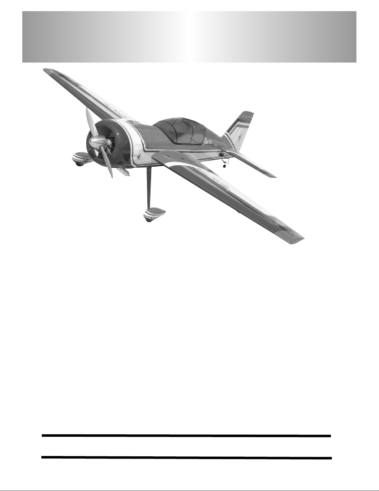
Aerobatic flying just doesn't get any better than this Yak54. The classic lines of a world class aerobatic plane
coupled with the radial cowl, add excitement to the maneuvers you love, knife edge, split S, lumcevac, torque
rolls, snaps, and ground-hugging inverted flight. What's more, we've engineered this ARF to get you into the
air with a minimum of fuss. So take a few minutes to carefully read the introductory material and then get to
work. You'll soon be out at the field with a classic aerobatic champion!
Y
Y
a
a
k
k
5
5
4
4
©copyright 2005 Carl Goldberg Products, Ltd.
Page 2
2
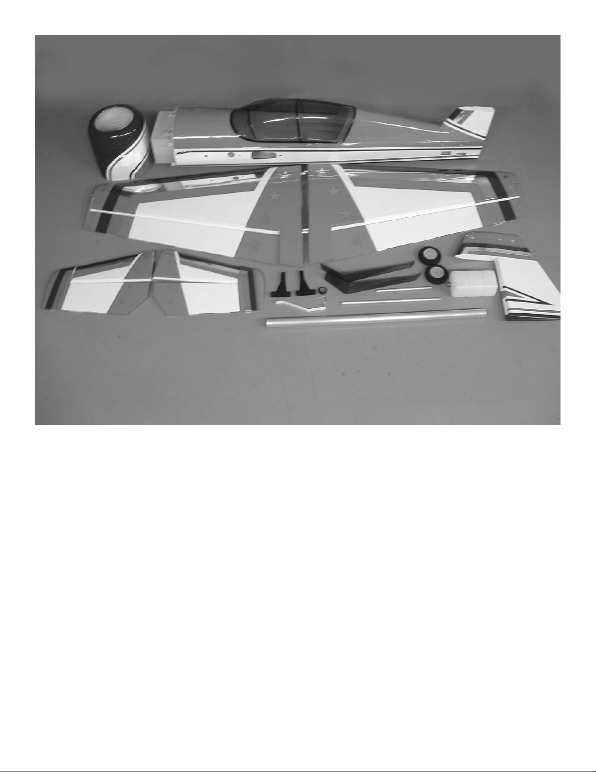
Cowl
Fuselage
Clear canopy
Left wing panel with aileron
Right wing panel with aileron
Stab half left
Stab half right
Elevator left
Elevator right
Motor mounts
Tail wheel bracket
Main gear
Wheels
Stab spars(aluminum tubes)
Wing tube (aluminum tube)
Fuel tank
Rudder
Page 3

3
Before you begin assembling your Yak 54 ARF, take some
time to read through this entire instruction book. It is
designed to take you step-by-step through the process and
to give you added information on engine and radio selection
and set-up, balancing your aircraft, and flying your model.
The time you spend will speed the assembly process and
help you avoid problems.
PREPARING FOR ASSEMBLY
You will need a work area of approximately 24 x 70" which has been
covered to protect it from adhesive, as well as cuts and other
damage. Many people cover their work area with a sheet of
dry wall (sheet rock) and/or waxed paper t o prevent CA
Glue and Epoxy from ruining the work surface.
CONSTRUCTION TIPS
IMPORTANT: ALWAYS READ A FEW STEPS AHEAD.
This will alert you to coming instructions and will help you
plan accordingly.
Using the Parts Identification section, familiarize yourself
with the various items included in your kit box.
As you work, CHECK OFF EACH STEP in the box provided, so that you are sure you do not forget anything.
Do not hesitate to ask questions. Your local hobby dealer
and area flyers will most likely be happy to help, as they
want you to have a successful flying experience. You may
also receive technical assistance from Carl Goldberg
Products, Ltd. by telephone 1-678-450-0085.
ADHESIVES & GLUING TECHNIQUES
CA adhesives are specially formulated to firmly glue the plywood, hardwood, and balsa used in your model and to withstand the vibration and stresses of high performance flight.
However, there are times, such as when you are installing
the stabilizer and fin on the fuselage and want more setup time for careful alignment and positioning, then you
should use epoxy.. Occasionally, you also will want to use
thin CA, which "wicks" into the surrounding areas. Aliphatic
resin glue or similar water-based glues can also be used,
but they will add to the assembly time because they dry so
much more slowly than CA glue. Remember, when ever
using any CA, you must be careful to read instructions thoroughly, as you will have only seconds for positioning of
parts. Be sure to trial fit parts together before gluing. Also,
never use watery THIN type CA glue for gluing plywood and
hardwood parts. Thin CA's do not adequately bond these
areas.
CAUTION
Some people may experience an allergic reaction when
exposed to fumes from CA glue or epoxy. As with paints,
thinners, and solvents, it is always important to use glues
only where there is adequate ventilation to carry fumes
away. A fan is recommended. Also, special care must be
taken when using CA, as it will bond skin as well as other
surfaces. Before using any CA, carefully read all label precautions. When using CA, protective eye-wear and care in
keeping the glue away from the face is highly recommended. If CA does happen to get into the eye, hold lid open and
flush with water only. Seek immediate medical attention.
COVERING
The Yak 54 ARF is covered in a premium polyester film
chosen by many of the world's top flyers for its beauty,
toughness, and ease of application and repair. It is not
uncommon for ARF's to develop a few wrinkles in transit. If
this is true of your model, the situation is easily corrected.
Before you begin putting the pieces together, run over the
surface of each section with an iron (either specially
designed for airplane use or the more cumbersome household iron) or use a modeling heat gun. Apply the heat (set
at about 350° F), following along with a soft cloth and pressing down on the covering as you go around. This will more
firmly set the covering adhesive into the wood and keep
your aircraft covering tight and smooth in the future.
One of the great advantages of polyester film is that it can
be applied over itself without causing gas bubbles. This
allows you to repair your aircraft, as well as to customize it
in a number of ways. If, due to a flight mishap, you get a
hole or similar covering damage, simply trim away the
ragged edges and then apply a patch, following the directions that come with your covering , which is available at
your hobby dealer.
Important Information
Covering coming loose is not COVERED UNDER WARRANTY. Due to
temperature changes the plane may
develop some wrinkles in the covering that you will need to remove with
an iron. Be sure to seal the edges
down first so that you do not cause
the covering to shrink and leave
exposed areas of wood. Please
inspect the plane before beginning
to assemble to make sure you are
happy with it. After assembly has
begun you cannot return the kit. If
you find a problem before beginning
to assemble the plane you must
contact us, please do not return it to
the dealer.
Page 4

4
ITEMS NEEDED TO COMPLETE THIS AIRCRAFT
1 RADIO GUIDANCE SYSTEM (4 CHANNEL
MINIMUM REQUIRED WITH 8 SERVOS)
2 12” AILERON SERVO EXTENSION WIRES
2 24” ELEVATOR SERVO EXTENSION WIRES
3 Y-HARNESS
1 ENGINE and PROP
1 CA ACCELERATOR
1 2 OZ. BOTTLE CA MEDIUM GLUE
1 1/2 OZ. BOTTLE CA THIN GLUE
1 20 MINUET EPOXY
1 1/4” FOAM RUBBER
OPTIONAL:
1 1/5 PILOT FIGURE
1 SPINNER 2-1/2” to 3-1/2”
NOTE: The Yak ARF covering matches Midnight
blue #885, Flame red #883, and White
,#870.
TOOLS AND SUPPLIES FOR ASSEMBLY.
MODELING OR UTILITY KNIFE
WORK SURFACE (24" X70")
ELECTRIC DRILL
1/16”, 3/32”,1/8", 3/16”, 5/32”, 1/4”, 5/64”
7/32” DRILL BITS
SMALL STANDARD & PHILLIPS SCREW-
DRIVERS
MASKING TAPE
NEEDLE NOSE PLIERS
MOTO TOOL
24” RULER
FLEXIBLE STRAIGHT-EDGE
30-60-90° x 6" TRIANGLE
SOFT PENCIL
A FEW STRAIGHT OR "T" PINS
ADJUSTABLE WRENCH
WIRE CUTTER (DYKES)
OPTIONAL HEAT GUN/COVERING IRON
ACID BRUSH
ELECTRICAL TAPE
PIECE OF MEDIUM SANDPAPER
5 FT. LENGTH OF STRING
Caution:
Before starting, carefully go over all high
stress areas with an epoxy or wood glue to
confirm all areas are well glued.
Page 5
5
WING ASSEMBLY
AILERON INSTALLATION
2 Start with one wing panel. Locate the ailerons
and trial fit them on the wing. Make sure all the
hinges are aligned.
Now locate the other aileron and wing panel
and fit the aileron. When you are satisfied with
the fit, remove the ailerons and lay them
behind the wing in the correct position. The pin
style hinges work best if installed in both wing
and aileron at the same time. Apply a drop of
oil in the hinge.Use 30 minute epoxy to glue
them in.
Note: A syringe works great, if you have one
use a 1/8” dowel or piece of 3/32” wire to get
the epoxy into the holes. With glue in the
holes, push the hinges in wing up to the pin.
Apply glue in the holes on the aileron and slide
aileron into place. Work the aileron up and
down several times and the pin hinges will
rotate into position. Make sure you have a tight
fit between the wing trailing edge and aileron
leading edge.
Set aside to dry and install the other aileron.
AILERON SERVO INSTALLATION
Note: The following pictures may not exactly match
the hardware you are using. Always check the
radio manufacturer's instructions when installing
radio equipment.
1. Collect the following items:
(4)Servo mounting screw (supplied with
radio)
(1)Servo with rubber grommet (supplied with
radio)
(2) Servo extensions 12”
(2) y-connectors
IMPORTANT! To ensure that any connections locat-
ed inside the wing will not come loose, either when
the wires are pulled, or during flying, always tape
them securely together with electrical tape.
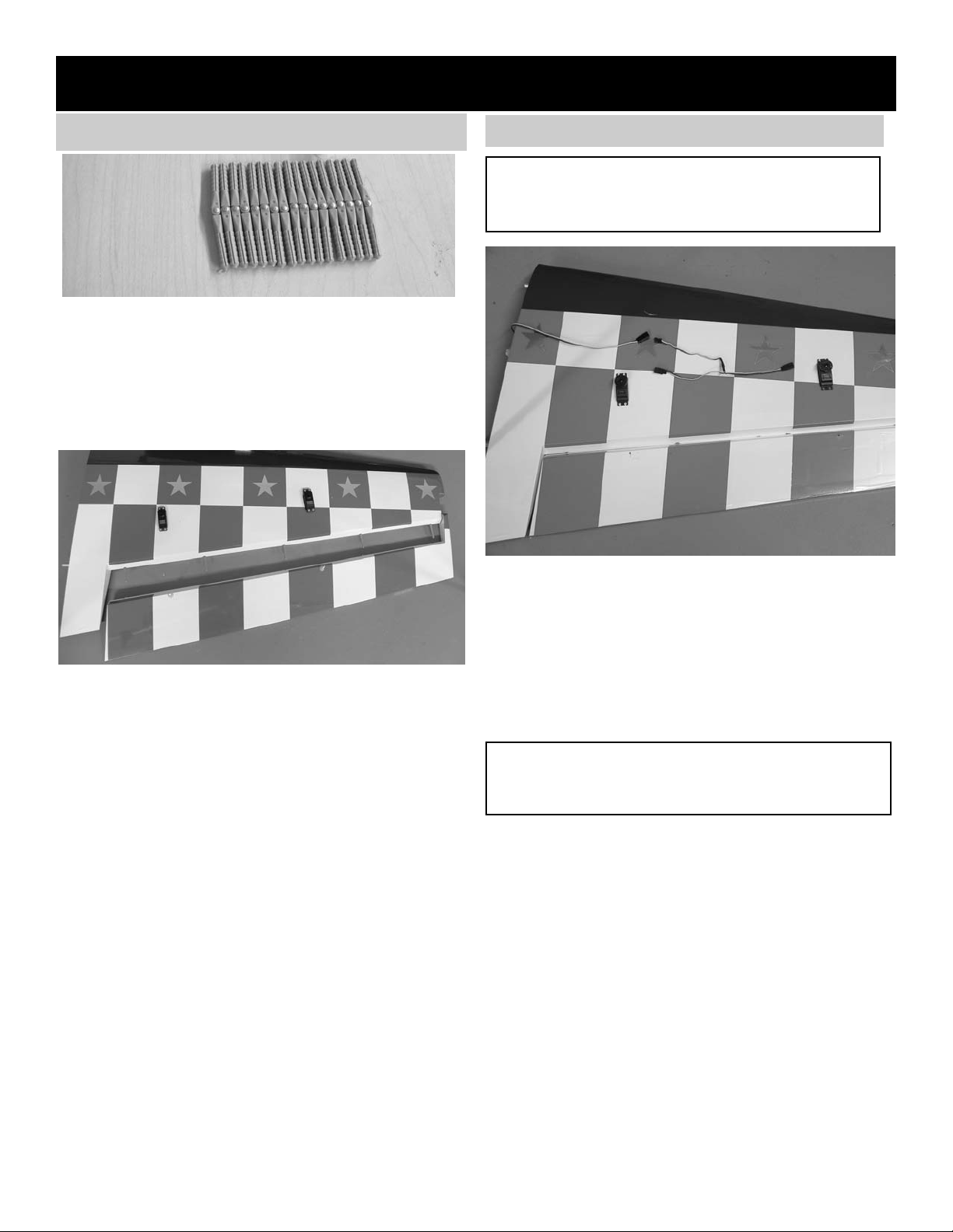
2. Making sure to use the correct servo for the
opening, attach the servo wire to the y-con-
nector and securely tape the connection.
Push the y-connector wire into the wing until it
comes out the other servo hole near the cen-
ter of the wing.
3.
Connect the other servo and and the 12”
extension to the end of the y-connector.
Install the servo with the output arm forward.
4.
Grasping the extension in the hole, SLOWLY
pull until the end of the extension comes out
of the hole at the center of the wing..
Tape the extension securely to the wing, so
that it will not slide back in while you are work-
ing.
1. Collect the following parts:
(1) Left wing
(1) Right wing
(1) Left aileron
(1) Right aileron
(10) pin hinges
Page 6

6
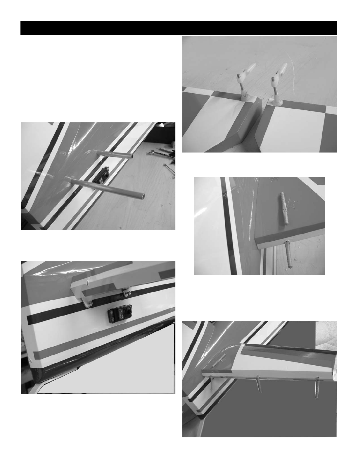
AILERON CONTROL HORN INSTALLATION
1. Collect the following items
(4) Nylon clevis assemblies
(4) nylon ball nuts
(4) 6-32 x 3” Bolt
(4) nylon washers
(4) 4-40 x 4” pushrods
(4) 4-40 clevis
(4) clevis keepers
2. With the aileron servo in place, make a mark
at a 90º degree angle to the trailing edge and
in line with the servo arm.
3.
Use the mark to locate the hard point installed
in the aileron( dowel with hole in middle).
4. Using a 9/64" drill bit, open the hole in the
aileron through to the top side.
HINT: Drill the hole from the bottom half way. Then
drill down to the hole from the top of the
aileron.
5. Insert the 6-32 x 3” screw from the top through
the aileron.
Place the nylon washer and the nylon ball nut
on the bolt and tighten.
Screw the adjustable clevis assemble on the
bolt.
6. Thread on to one end of a 4-40 x 4” pushrod
a nut and clevis.
Mount the pushrod onto the nylon clevis
assemble on the aileron.
With the servo centered, connect the pushrod
to the control horn.
With one servo connected and the radio on,
connect the other servo pushrod making sure
that there is no pressure on the other servo.
Install the clevis keepers.
Repeat the above steps for the other two
aileron servos.
Page 7
7
Collect the following items
(1) Stab
(1) Fuselage
(1) Stab halves
(6) pin style hinges
(4) 4-40 x 1/2” bolts
(2) aluminum stab tube
(2) 6-32 x 3” bolts (control horns)
(2) nylon ball washers
(2) nylon ball nuts
(2) nylon clevis assemblies
Tail Construction.
1. Install the two aluminum stab tubes in the fuse-
lage with the longer one in the rear.
2. Slide the stab half onto the tubes and tightly
against the fuselage side. Install the two 4-40
x 1/2” bolts into the mounting tabs on the bottom of fuselage. Blind nuts are pre-mounted in
the fuselage. Be sure to use lock-tite on the
bolts. Repeat for the other stab half.
3. Install the control horns on the elevators in the
same manner as you did the ailerons.
4. Because of the location of the stab tube, the
inboard elevator hinge will have to be cut off at
the end of the second serration, cut off 1/2”.
Make sure hinge will go into stab up the hinge
pin.
Page 8

8
5. Install the other two hinges. Trial fit the eleva-
tors in place making sure they will fit tightly
against the trailing edge of the stab and work
smoothly.
When satisfied with the fit, remove elevator
and apply epoxy in the holes the same as with
the ailerons. Work the elevators up and down
several time and set aside to dry..
1. Collect the following items:
(1) Rudder
(1) 6-32 x 4” threaded rod
(2) nylon ball washers
(2) nylon ball nuts
(2) nylon clevis assemblies
(2) nylon pushrod connectors
(3) Pin style hinges
1. Insert the three hinges in the fin until the hinge
pin is on the hinge line. Fit the rudder in place
on the hinges.
2. Locate the exit hole in the side of thefuselage
for the rudder pull-pull cable. Using a straight
edge, mark the location of the control horn on
the rudder in line with the hole
3.
Drill a 9/64” hole at the location you just
marked. Drill half way from each side as you
did on the ailerons.
1. Collect the following items.
(2) Landing gear legs
(6) 6-32X3/4” Socket head screws
(6) #6 flat washers
(2) Wheel pants, one left one right
(2) 4mm axels with lock nuts
(4) 4mm wheel collars
(2) 3-1/4” wheels
(2) 4-40 x t-nuts
(2) 4-40 x 1/2” socket head bolts
2. Slide gear leg into slot on side of fuselage and
install retaining bolts through the gear legs
from the inside of the fuselage.Be sure to use
thread lock on the bolts. The blind nut are
already installed.
Rudder Installation
4. Install the 4” threaded rod with a ball washer
and ball nut on each side. Center the bolt in the
rudder. Install the nylon pushrod connector for
the tail wheel steering springs and then the
nylon clevis assemblies. Repeat for the other
side.
5. Trial fit the rudder in place making sure the
hinge line is tight against the fin. When satisfied with the fit glue the hinges in place using
the same procedure you did with the ailerons.
Landing Gear Installation
Page 9

9
3. Install each axel using the locking nut. Be
careful not to over tighten the nut, it looks like
a large bolt but it has been drilled out for the
axel and can be broken if too much torque is
applied.
4. Install one wheel collar on each axel with 3/16”
between the collar and the axel nut. This will
space the wheel in the center of the wheel
pant.
5. The wheel pants have the 1/2” hole predrilled
in each pant. The 1/8” hole for the mounting
bolt must be drilled.
7. Remove the wheel pant and drill a 5/32” hole
at the location you marked. Insert the blind nut
on the inside and pull it tight using the 4-40
mounting bolt. Lock in place with CA glue
being careful not to get it in the threads.
6. Block the tail of the plane up so that the fuse-
lage is sitting level. Put the wheel inside the
pant and slide both on the axel together.
While holding the wheel pant level, mark the
location of the mounting bolt by using a 1/8”
drill and inserting it through the predrilled hole
on the landing gear leg
Page 10

10
8. Reinstall the wheel and wheel pant and retain
with the other 4mm wheel collar. Align the
wheel pant on the gear leg with the hole you
drilled for the blind nut. Install the 4-40 x 1/2”
socket head screw.
Don’t forget to use locktite to make sure it does
not come loose.
Repeat for other wheel pant.
Tail wheel Mounting
1. * Collect the following parts:
(1) tail wheel bracket
(1) tail wheel
(1) 1/8” wheel collars
(2) tail wheel springs
(2) 3mm x 1/2” sheet metal screws\
(2) bracket collars
(2) nylon horn brackets(2) 3mm x 1-1/2” threaded rod
2. Build up the tail wheel assembly by putting the
tail wheel on the axel and retaining with the
1/8” wheel collar. Install the bracket collar
(without holes on each side) on the shaft.
Insert the shaft through the mounting bracket
and install the bracket collar. Screw the threaded rods into the bracket on each side. Make
sure the tiller arms are square to the tail wheel
and tighten the screw. Use locktite on the
screw.
Install the nylon horn brackets on each end of
the threaded rod.
Bracket collars
3. Install the tail wheel bracket on the fuselage by
drilling a .050 hole at each locations and
mounting with the two 3mm x 1/2” screws.
4. Install the tail wheel springs between the rud-
der horn bracket and tail wheel horn bracket.
Page 11

11
Elevator Servos
1. Collect the following parts:
(2) 4-40 x 2-3/4” threaded pushrods
(2) metal clevis
(2) 4-40 nuts
(2) clevis retainers
2. Install the elevator servos in the fuselage side
with the output arm forward.
3. Be sure and use the forward hole for the elevators. There is an optional rudder servo hole.
Do not remove covering from this opening if
using the pull-pull rudder servo setup. The rudder servo can be mounted in the tail if a heavy
motor is used and weight is need in the rear.
The 1.2 to 1.6 two and four stroke motors are
not heavy enough to mount the servos in the
tail.
4. Thread the 2-3/4” pushrod into the clevis
assembly on the rudder horn. Install the nut
and metal clevis on the other end and attach to
servo. arm. Install the clevis keeper. Repeat
for the other elevator servo.
Rudder Servo Tray Installation
1. Locate the servo tray, front bulkhead, and rear
bulkhead.
front bulkhead
rear bulkhead
servo tray
Page 12

12
2. Epoxy the rear bulkhead in place with the
notch on the bottom fitting over the receiver tray
and flush against the bulkhead.
3. Epoxy the servo tray to the rear bulkhead
making sure the servo cutout is to the rear of the
wing tube.
4. Epoxy the front bulkhead in place sitting on
the cockpit floor and back against the bulkhead.
5. If you are using a large motor you may want
to install a piece of tri-stock (not included) along
the front side of the servo tray and the bottom of
the wing tube. This will add strength to the servo
tray.
Rudder Servo
1. * Collect the following parts:
(2) braided steel cable
(2) metal clevis
(2) 4-40 nuts
(2) clevis retainers
(4) threaded cable couplers
(4) cable swages
2. Mount the rudder servo in the tray supplied just
behind the wing tube.
Page 13

13
2. Thread the cable through one of the swages
then through the hole in the end of the threaded coupler and back through the swage.
3. Loop the cable back through the swage then
crimp the swage with a pair of pliers.
4. Screw the threaded coupler with cable
attached into the nylon clevis assembly on the
rudder horn.
5. Thread the cable into the access hole in the
side of the fuselage.
Repeat for the other cable.
rudder cable access hole
threaded coupler with cable
6. Take the other two threaded couplers and
install a nut and clevis on each.
7. Install the two clevis assemblies on a double
control arm.
Center the servo and attach the control arm.
Tape the rudder in place centered.
Page 14

14
8. Pull the rudder cables to the servo and thread
a swage on each. Fit cable through hole in
threaded coupler and back through the swage.
Do both cables at the same time and pull both
tight before crimping swage. Make sure servo
is centered and rudder is centered. Pull both
cables tight and crimp swage.
Engine Installation
1. Collect the following items:
(2) Motor mounts
(4) 4 mm bolts
(4) 4mm blind nuts
(4) flat washers
(4) 3.5mm x18mm screws
2. Draw a line across the firewall in the center.
Draw a line down the firewall offset 3/16” to the
left side of the plane. The 3/16” will compensate for the 2 degrees of right thrust built into
the firewall. Note: The firewall will have a 1“
hole in the center not shown on the photo.
3. Clamp your motor between the beams of the
two mounts and set flat on the work bench.
Make sure the motor is square to the table and
both mounts sit flat.
Put a scrap piece of wood in the prop mount
and measure both sides to make sure it is
square. The distance from the table to the front
of the thrust washer (scrap wood ) will have to
be at least 6-1/4” to clear the front of the cowl.
If you cannot get this much by moving the
engine to the front of the mounts, you will have
to shim the mounts out. Our OS 1.20 fit all the
way to the end of the mounts.
4. With the motor clamped in place, mark the
location of the mounting holes. Drill a 1/8” hole
and screw the motor in place using the 3.5mm
screws. Be careful and don’t over torque the
screws or they will break.
Page 15

15
6. Seat the blind nut by using one of the 4mm
bolts and a flat washer without the mounts.
Pull the blind nut firmly into the firewall using
the screw. Repeat for the other 3 screws.
7. Bolt the engine in place being sure to use lock-
tite on all the screws.
8. Drill a 9/64” hole in line with the throttle output
arm on your engine and insert the nylon tube for the
throttle pushrod.
Throttle Servo
1. Collect the following items:
(1) e-z servo connector
(1) Laser cut plywood mount
(1) 2-56 threaded one end pushrod
(1) 2-56 clevis
(1) clevis retainer
5. With the motor on the mounts, center the
mounts on the two line you drew on the firewall.
Mark the location of the holes and drill a .160
diameter hole at each location.
Open the hole up with a .200 diameter drill (the
shoulder of the blind nut is .200)
Page 16

16
3. Mount the servo to the mount using the hardware supplied with the servo.
4. The throttle servo mount can now be mounted
in a position to match your engine.
5. Locate the e-z pushrod connector and install on
your servo arm.
6. Thread the 2-56 clevis on the pushrod and
insert into the plastic tube. Connect the clevis
to the throttle arm on the motor. Connect the
other end of the pushrod to the e-z connector
on the throttle servo and adjust.
2. Assemble the throttle servo mount by gluing
the 3/8” square rails in the corners of the 1/8”
plate and gluing the triangle gussets under the
rails.
Page 17

17
Fuel Tank
1. Collect the following items
(1) fuel tank
(1) rubber tank stopper
(1) clunk
(1) 3mm x 25mm screw
(1) cap washer large
(1) cap washer small
(2) 3mm x 40mm brass tube
(1) 3mm x 60mm brass tube
2. Insert the 3mm screw through the center hole
in the large washer, through the center hole in
the rubber washer against the large side, and
screw the small washer on the back side.
3. Insert the brass tubes through three of the
holes. They should be arranged so as the long
one will be on the right side of the plane and
the short one on the left side.
The tubes should extend out the front of the
cap 5/8”. Bend the long tube up at about a 20
degree angle. This should be adjusted so the
end of the tube almost touches the top of the
tank when installed.
4. Install the 4mm silicone tube to the short brass
tube and install the clunk to the other end of
the silicone tube. This is the fuel pickup and
must be free to“flop” around in the tank so it
can pick up fuel in any attitude.
(note: If you use gasoline you must use
neoprene fuel line, glow fuel use
silicone fuel line.)
5. Install the assembly into the tank so the vent
tube is turned up to the top of the tank. Tighten
the screw to expand the rubber cap.
Don’t over tighten or you could split the tank.
Page 18

18
6. Install the tank with the cap in the hole in the
firewall. A tank support is provided to hold the
tank in place. Locate the 1/4” x 3/4” x 7-1/2”
piece of plywood and glue across the fuselage
behind the tank to hold the tank in place. It will
fit just above the throttle servo .
tank support
Cowl Mounting
1. * Collect the following items:
(1)Cowl
(4) 4-40 x 1/2” bolts
(4) #4 flat washers
(1) silicone tubing 1/4” long
3. Fit the cowl in place under the pieces of paper
making sure the stripes line up and cowl is
straight. Use masking tape to hold the cowl in
place.
Transfer the holes from the paper to the cowl.
Drill a 7/32” hole at the four locations. The
blind nuts are pre-installed in the mounting
blocks. Fit the 1/4” long pieces of silicone tubing in the holes and insert the 4-40 x1/2”
screws with a flat washer on top. The silicone
tubing will act as a grommet and protect the
fiberglass.
2. Cut two pieces of scrap paper about 1”: wide
and 6” long and tape to the side of the fuselage
so the end of the paper is over the mounting
hole for the cowl.
Mark the location of the holes in the paper.
Page 19

19
4. Remove the cowl and mount the muffler on the
engine. Use another piece of paper and cut to
fit around the muffler. Mark the location of the
paper on the fuselage so you can relocate it
after the cowl is reinstall..
5. Reinstall the cowl and fit the paper in place on
the fuselage and mark the location of the hole
for the muffler. Repeat for the other holes in
the cowl.
6. When mounting the cowl for flight, use locktite
on all the bolts.
Page 20

20
Canopy and Hatch Mounting
1. Collect the following items:
(1)Hatch
(1)Canopy
(2)4-40 screws
2. Fit the hatch in place with the dowels in front
and the tabs in the rear.
3.
Use the two 4-40 screws through the side of
the fuselage to hold in place.
mounting screw
Page 21

21
4. Install pilot and cockpit detail if desired (not
included).
5.
Glue the canopy in place using Zap canopy
glue. Do not glue the canopy in place without
the hatch cover mounted on fuselage and
screwed in place. It is easy to distort the hatch
and it will not fit properly if not mounted while
gluing the canopy on.
Switch and Battery Mounting
1. The prototype balanced with an OS 1.2 four
stroke with no added weight by putting the battery pack on top of the motor box under the
cowl.
2. The switch can be mounted in the balsa sheeting under the wing on either side.
Balance and Control Throws
CG Balancing
Balancing the Yak is very important, you
might need to use weight depending on
the servos and engine that you use. Start
out with the balance point at 6-1/4”. This
balance point is a safe place for you to fly
the Yak at. As you get comfortable you
can move the CG back further. The further you move the CG the more wild the
aerobatics will become, BUT the more
unstable the Yak will become
Throws
We have provided two sets of throws.
Use the lower throws on the first flights
then work your way up to the higher
throws. Do not use the higher throws till
you are ready.
LOW HIGH
Elevator 1” UP& Down All you can get
Ailerons 3/4” Up & Down All you can get
Rudder 1-1/2” Right & Left All you can get
When you have gotten comfortable
flying the YAK slowly increase the throws
while still staying within your flying ability.
Flutter Problems
Any model with large control surfaces such as the
Yak can experience flutter. It is your responsibility to
make sure all linkage is in good order and very tight.
Servos must be in good shape with control arm that
are not worn. You must fly the plane in a manner
that does not cause it to over speed , you must use
throttle management. Flutter is not covered under
warranty.
 Loading...