

Page 1

Extra 330 ARF
Extra 330 ARF
WARNING
A radio-controlled model is not a toy and is not intended for persons under 16 years old. Keep
this kit out of the reach of younger children, as it contains parts that could be dangerous. A radiocontrolled model is capable of causing serious bodily injury and property damage. It is the buyer's
responsibility to assemble this aircraft correctly and to properly install the motor, radio, and all other
equipment. Test and fly the finished model only in the presence and with the assistance of another
experienced R/C flyer. The model must always be operated and flown using great care and common
sense, as well as in accordance with the Safety Code of the Academy of Model Aeronautics (5151
Memorial Drive, Muncie, IN 47302, 1-800-435-9262). We suggest you join the AMA and become properly insured prior to flying this model. Also, consult with the AMA or your local hobby dealer to find an
experienced instructor in your area. Per the Federal Communications Commission, you are required
to use only those radio frequencies specified "for Model Aircraft."
LIMITED WARRANTY
Carl Goldberg Products, Ltd. has inspected and certified the components of this aircraft. The company urges the buyer to perform his own inspection, prior to assembly, and to immediately request a replacement of any parts he believes to be defective for
their intended use. The company warrants replacement of any such components, provided the buyer requests such replacement
within a period of 90 days from the date of purchase and provided the defective part is returned, if so requested by the company.
No other warranty, expressed or implied, is made by the company with respect to this kit. The buyer acknowledges and understands that it is his responsibility to carefully assemble the finished flying model airplane and to fly it safely. The buyer hereby
assumes full responsibility for the risk and all liability for personal or property damage or injury arising out of the buyer's use of the
components of this kit.
CARL GOLDBERG PRODUCTS, LTD.
P.O. Box 818 Oakwood GA 30566 Phone #678-450-0085 Fax # 770-532-2163 www.carlgoldbergproducts.com
©copyright 2004
Page 2

2
Congratulations on your purchase of the Extra
330ARF. This is a very unique dual-purpose aircraft, capable of flying any FAI pattern
sequence with ease, while exhibiting remarkable 3-D capabilities. Every effort has been
made to produce a lightweight, straight, easy to
assemble aircraft. Because of its oversize control surfaces which are double beveled to allow
for extreme throws, great care must be taken in
the set-up and flying of this airplane. Quality
hardware components have been provided to
allow for 3D set-up while maintaining adequate
mechanical advantage to eliminate flutter. It is
you responsibility as an advanced pilot to fly the
aircraft in an intelligent manner. THROTTLE
MANAGEMENT IS A MUST!!!!!!! Carl
Goldberg Products has flown the Extra 330ARF
through a very rigorous flight-testing schedule
and have stressed the airframe beyond all practical parameters without a single failure. Carl
Goldberg Products will NOT
warrant the Extra
330ARF against flutter due to improper set-up
or excessive speed maneuvers. having said
that, we believe you will find the Extra 330ARF
to be one of the most responsive, in-the-grove
aircraft on the market. Just remember to use
common sense when flying this high performance machine.
We are very proud of the construction of the
Extra 330ARF and all of our other ARF aircraft.
Each aircraft is jig built to insure a straight true
airframe. Every effort is made to build as light an
aircraft as possible. As with any professional
builder, glue is used sparingly. Please take a
moment during assembly and run a bead of
CA or aliphatic resin into the high stress
joints that you can reach such as the landing
gear plate, servo mounting trays, wing hold
down blocks, etc. Also, during the course of
shipping from the manufacturer to our facility in
the United States, it is not uncommon for the aircraft to experience several changes in climate.
This may cause the iron-on covering to develop
wrinkles. This is not a fault of the manufacturer.
Please take a few minutes with your heating iron
and heat gun to iron down the seams and reshrink the covering where needed. The results
will be a beautiful aircraft with a breathtaking finish that you will be proud to display at your flying
club.
Before beginning assembly of your Extra
330ARF, we highly recommend that you study
this manual in its entirety. You should begin
planning your radio installation based on your
choice of engine and equipment from the beginning.
Because the Extra 330ARF is intended for
those with some degree of modeling experience, every minute detail will not be covered.
This is not a basic trainer. Assembly of this aircraft will be easy for the experienced modeler,
and by following the instructions within this
manual and using the skills you’ve gained during your modeling career you will be able to produce a first class aircraft.
Building supplies needed
Hobby knife w/#11 blades
Thin CA
Medium CA
Canopy glue
30 minute epoxy
Thread lock
Diagonal wire cutters
Pliers
Assorted drill bits
Various sized screwdrivers( both Phillips and
standard head)
Tape measure
Dry-erase marker
Paper towels
Rubbing alcohol
Electrical tape
4-40 Tap & Die Set
3/32, 7/64, 9/64 & 3mm Allen wrench
Wax Paper
Note:
Thread lock must be used where
ever any machine bolts are going into
any type of nuts. If you do not use
thread lock the bolts could become
loose and fall out in flight.
Page 3

3
ADHESIVES & GLUING TECHNIQUES
CA adhesives are specially formulated to firmly glue the
plywood, hardwood, and balsa used in your model and to
withstand the vibration and stresses of high performance
flight. However, there are times, such as when you are
installing the stabilizer and fin on the fuselage and want
more set-up time for careful alignment and positioning,
then you should use epoxy. Occasionally, you also will
want to use thin CA, which "wicks" into the surrounding
areas. Aliphatic resin glue or similar water-based glues can
also be used, but they will add to the assembly time
because they dry so much more slowly than CA glue.
Remember, when ever using any CA, you must be careful
to read instructions thoroughly, as you will have only seconds for positioning of parts. Be sure to trial fit parts
together before gluing. Also, never use watery THIN type
CA glue for gluing plywood and hardwood parts. Thin CA's
do not adequately bond these areas.
CAUTION
Some people may experience an allergic reaction when
exposed to fumes from CA glue or epoxy. As with paints,
thinners, and solvents, it is always important to use glues
only where there is adequate ventilation to carry fumes
away. A fan is recommended. Also, special care must be
taken when using CA, as it will bond skin as well as other
surfaces. Before using any CA, carefully read all label precautions. When using CA, protective eye-wear and care in
keeping the glue away from the face is highly recommended. If CA does happen to get into the eye, hold lid open
and flush with water only. Seek immediate medical attention.
PREPARING FOR ASSEMBL
Y
You will need a work area of approximately 24 x 48" which has
been covered to protect it from adhesive, as well as cuts and
other damage. Many people cover their work area with a
sheet of dry wall (sheet rock) and/or waxed paper t o prevent CA Glue and Epoxy from ruining the work surface.
CONSTRUCTION TIPS
IMPORTANT: ALWAYS READ A FEW STEPS AHEAD.
This will alert you to coming instructions and will help you
plan accordingly.
Using the Parts Identification section, familiarize yourself
with the various items included in your kit box.
COVERING
The
EExxttrraa 333300
ARF is covered in a premium polyester film
chosen by many of the world's top flyers for its beauty,
toughness, and ease of application and repair. It is not
uncommon for ARF's to develop a few wrinkles in transit.
If this is true of your model, the situation is easily corrected. Before you begin putting the pieces together, run
around the edge of the seams first then over the surface
of each section with an iron (either specially designed for
airplane use or the more cumbersome household iron).
Apply the heat (set at about 350° F), following along with
a soft cloth and pressing down on the covering as you go
around. This will more firmly set the covering adhesive
into the wood and keep your aircraft covering tight and
smooth in the future. Once you have ironed the seams
stay away from them with the heat or the covering will
slide when you try to shrink the middle. If this happens the
wrinkles will not come out of the covering.
ITEMS NEEDED TO COMPLETE THIS AIRCRAFT
1 RADIO GUIDANCE SYSTEM (6 CHANNEL
MINIMUM REQUIRED WITH 8 SERVOS)
2 24” ELEVATOR SERVO EXTENSION
WIRES
2 24” Y-HARNESS
1 CA ACCELERATOR
1 2 OZ. BOTTLE CA MEDIUM GLUE
1 1/2 OZ. BOTTLE CA THIN GLUE
1 30 MINUET EPOXY
1 1/2” FOAM RUBBER
1 3” SPINNER
OPTIONAL:
1 1/4 SCALE PILOT FIGURE
NOTE: The Extra 330 ARF covering closely
matches Bright Yellow (#872), Flame Red
(#883), Deep Blue (#873) and White (#870)
Oracover.
Page 4

4
2. Locate the pre-drilled aileron hinge holes in both
wing halves. Using a 1/4” drill, drill each hole
1/8” deep. This will allow the center of the hinge
to be inserted half way into each of the surfaces.
Repeat this process with the ailerons, making
sure all hinges insert half way.
3. Place 1 drop of oil on each of the hinges at the
center. This is to keep the hinges loose and
prevent epoxy from sticking at the joint.
Caution: Do not get any oil on the length of the
hinge or it will not glue into the surface.
WING ASSEMBLY
AILERON INSTALLATION
1. Collect the following parts:
(1) Left wing
(1) Right wing
(1) Left aileron
(1) Right aileron
(10) hinges
4. Select the aileron for the wing half on which
you are working.
Mix up a liberal amount of 30 minute epoxy.
Working with 1 hinge at a time, place a dab of
epoxy and insert the hinge half way into one of
the aileron holes.
Repeat for each of the other hinges for that
aileron.
5.
Working quickly, place some epoxy on the
second half of each hinge and insert the
aileron into the wing.
Slide the aileron toward the wing until no gap
remains between the aileron and the wing.
When satisfied with the alignment, flex the
aileron up and down to confirm that the hinges
are working freely. remove any excess epoxy.
Apply a few strips of masking tape to keep the
pieces in place.
Allow to dry before flexing the aileron.
6.
Repeat the above steps for the other half of
the wing.
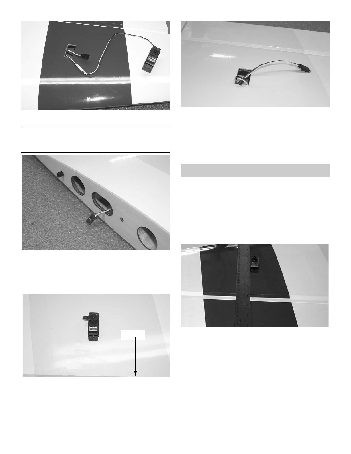
AILERON SERVO INSTALLATION
1. Collect the following parts:
(1) Left wing
(1) Right wing
(4) Servos
(2) 24” “Y” Harness
2. Locate the two servo holes in the bottom of
wing.
Carefully cut the covering over the servo
holes.
Page 5
5
3. Attach the 24” “Y” harness to one of the servos.
IMPORTANT! To ensure that any connections locat-
ed inside the wing will not come loose, either when
the wires are pulled, or during flying, always tape
them securely together with electrical tape.
4. Starting from the outer servo hole, insert
the “Y” harness and the servo wire into the
servo hole.
Allow the wire to fall straight down through
though the wing till it exits the root rib
.
5. Tape the end of the plug to the root rib.
Mount the outer aileron servo to the wing
.
Aileron
6. Pull the second half of the “Y” harness out
the inner servo hole.
Plug the second aileron servo into the wire
harness.
Always tape them securely
together with electrical tape.
Install the second aileron servo into the wing.
AILERON CONTROL HORN INSTALLATION
2. With the aileron servo in place, make a mark
on the aileron at a 90º degree angle to the
trailing edge and in line with the servo.
1. Collect the following items
(8) 4-40 Metal Clevis
(8) 4-40 Hex Nut
(4) 4-40 x 3-3/4" Double Threaded Wire
(4) 6-32 x 2” Bolt
(4) 6-32 Hex Nut
(4) #6 Washer
(4) 6-32 Adjustable Horn Bracket
(4) Clevis Clips
Page 6
6
3. Position the control horn bolt so that it is 1/2”
back from the hinge line on the mark that you
just made.
4.
Using a 9/64" drill bit, make a hole in the
aileron through to the top side.
5. Insert the 6-32 x 2” screw from the top through
the aileron.
Place the #6 washer and the 6-32 hex nut on
the bolt and tighten. Make sure that you use
thread lock on the bolt and nut.
Screw the adjustable horn bracket on to the
bolt.
6. Thread on to each end of the 4-40 x 3-3/4”
pushrod a hex nut and a metal clevis.
Install the metal clevis onto the horn bracket
and the servo arm.
Install a clevis clip on to each clevis and tight-
en the hex nut against the clevis.
Repeat the above steps for the second aileron
servo.
7.
Repeat steps 2 thru 6 for the second wing
half.
HINT: Drill the hole from the bottom half way.
Then measure and mark the top of the
aileron and drill down to the hole from the
top of the aileron.
Caution:
Make sure each snap link is fully closed and a
clip is installed before and after each flight.
Note:
Now is the time to decide if you want
to glue the stabilizer to the tubes and
the fuselage, or if you wish to have
removable stabilizers.
Collect the following parts:
(1) Left Stabilizer
(1) Right Stabilizer
(1) 1/2” x 16-1/4” Stabilizer Tube
(2) 4-40 x 1/2 bolts
Mounting Stab
1. Slide the small stabilizer tube into one side of
the stab. Then slide the assembly into the
hole in the fuselage till the stab is flush against
the fuse. (The side of the stab with the hole is
the bottom of the stabilizer). Slide the second
stab onto the tube sticking out the other side
of the fuselage. Squeeze both stab pieces
together firmly on to the fuselage.
Check that the stabilizer is level with the wing.
Shim the tube in the fuselage up or down if
necessary. Do not go any farther till the stab is
level to the wing.
The Stabilizer can be mounted to the
fuselage two ways:
Removable Stabilizer
1.
Using 4-40 bolt, drill and tap the stabilizer tube
at the hole location. This method will allow
you to remove the stab as needed. CAU-
TION:You must watch the bolt holes for
fatigue and drill another hole by rotating the
tube when this happens.
Page 7

7
Gluing Stabilizer:
1. Using a pencil, make an outline where the
stabilizer rest against the fuselage.
2. Remove both stabilizers from the tubes.
3. Remove the tubing from the fuselage.
4. Lightly sand the tubing using 220 sand paper.
5. Remove the covering from the fuselage
inside the outline that you made.
6. Mix up epoxy and slide the stabilizer assembly together again, allow to dry.
HINGING THE ELEVATORS
1. Collect the following items:
(2) Elevators
(6) Hinges
4. Take the elevators and the stabilizers and just
like you did for the ailerons pre-drill each of
then hinge holes.
Place a drop of oil on each of the hinges.
5. Mix up some 30 minute epoxy and glue each
of the elevators to the stabilizers.
Tape the elevators to the stabilizers till dry.
2. cut two barbs off of two hinges on one side
only.
3. Insert the shortened hinge into the hinge hole
closes to the fuselage.
Make sure that the hinge fits completely into
the stabilizer. Keep cutting the hinge till it fits.
ELEVATOR & SERVOS
1. Collect the following items:
(2) Servos
(2) 24” Servo Extensions
(2) 4-40 x 3-1/2” Double Threaded Pushrod
(4) 4-40 Hex Nuts
(4) 4-40 Metal Clevis
(4) Clevis Clips
(2) 6-32 x 2-1/2 “ Flat Head Bolt
(2) #6 Washer
(2) 6-32 Hex Nut
(2) 6-32 Horn Bracket
Note:
We have included a rudder servo hole in the
fuselage just behind and below the elevator
servo hole. If you choose to install a large
engine or just want better rudder control,
then install your rudder servo here(There is
a hole on both side of the fuselage for
push-pull system). More weight in the nose
will be required for this system.
1. Remove the covering over the elevator servo
holes on both sides of the fuselage.
Page 8

8
2. Plug the 24” extensions into the elevator ser-
vos.
Make sure that the extensions plugs are taped
to the servos.
3.
Screw the elevator servos into the fuselage.
4. Position the control horn bolt so that it is 1/2”
back from the hinge line and 3/4” from the end
of the elevator.
5.
Using a 9/64" drill bit, make a hole in the ele-
vator through to the top side.
6. Insert the 6-32 x 2” screw from the top through
the elevator.
Place the #6 washer and the 6-32 hex nut on
the bolt and tighten. Make sure that you use
thread lock on the bolt and nut.
Screw the adjustable horn bracket on to the
bolt.
6. Thread on to each end of the 4-40 x 3-1/2”
pushrod a hex nut and a metal clevis.
Install the metal clevis onto the horn bracket
and the servo arm. tighten the hex nut against
the metal clevis.
Install a clevis clip on to each clevis.
Repeat the above steps for the second eleva-
tor.
HINT: Drill the hole from the bottom half way.
Then measure and mark the top of the
aileron and drill down to the hole from the
top of the aileron.
Caution:
Make sure each metal clevis is fully closed and
a clip is installed before and after each flight.
RUDDER & TAILWHEEL
1. Collect the following items:
(1) 6-32 x 3” All threaded rod
(4) Small White Adjustable Horn
(2) 6-32 Hex Nut
(2) #6 Flat Washer
(1) Rudder
(3) Hinges
2. Install the hinges into the rudder and glue the
rudder in place using the same hinging
method used for the elevator and ailerons.
3. Position the control horn bolt so that it is 1/2”
back from hinge line and 1/2” up from the bottom of the rudder.
Using a 9/64" drill bit, make a hole in the rud-
der.
4.
Center the 6-32 x 3” threaded rod in the hole.
Using thread lock place first the #6 washer
then the 6-32 Hex nut on each side of the rudder.
Page 9

9
5. Thread the 2 white adjustable horn brackets
on the rod.
Do this on both sides of the bolt.
6. Thread the 6-32 x 3” threaded rod half way
into the brass nob that is on top of the axle on
the tailwheel bracket.
Place on the each end of the threaded rod a
white horn bracket.
Mark the center of the fuselage and place the
tail wheel bracket on the center line.
Place the first bend of the bracket where it
bends away from the fuselage just in front of
the rudder hinge line.
7.
Drill a 3/32“ hole in the first and last mounting
holes in the bracket
Mount the tailwheel bracket using 2 #6 x 1/2”
sheet metal screws.
8. Remove from the tailwheel springs approxi-
mately 1/2” from the other side of the long
wire.
On the side of the spring that you just cut off,
bend 2 or 3 coils of the spring out so that they
can hook through the horn bracket.
9. Twist the end of the spring on to the horn
bracket. Insert the long wire end around the
second horn bracket. Twist the wire so that it
will stay hooked to the bracket.
10.
Repeat steps 8 & 9.
Note: The springs do not have to be tight to work.
The wheel will pivot easily when ground
taxing.
Install the tailwheel using the 1/8” wheel col-
lars and set screws.
RUDDER SERVO
1. Collect the following items:
(1) Servo
(1) Cable
(2) Brass Tubes 1/16 OD x 1/4”
(2) 4-40 Rigging Coupler
(2) 4-40 Golden Clevis
(2) 4-40 Hex Nut
2. Cut the rudder cable in half.
3. Insert the cable into the hole found just above
the elevator servo.
Repeat for the other side cable.
Page 10

10
4. Remove the top canopy hatch. Reach down
inside the fuselage and pull the cables slowly
froward.
Caution: Do not pull the cables all the way
through the hole.
Tape the cables to the rudder servo tray..
5.
Slide one of the brass tubes over the cable
end next to the rudder.
Loop the end of the cable through the outer
horn bracket on the rudder control horn and
back though the brass tube.
Once more loop the cable around the out side
of the brass tube and pass it through the tube
for the third time. (See the photo above)
Pull on the end of the cable to make the final
loop as small as possible.
When satisfied then crimp the brass tube with
pliers.
Repeat step 5 for the second cable on the
other side of the rudder control horn.
6. Install the rudder servo in to the rudder servo
tray.
Note:
We have installed a double servo tray for
better rudder performance. This is a option.
We did not include the hardware for this
option.
7. Remove the cables from the servo tray.
Insert the cable through the brass tube and
then through the hole on the end of the rigging
couplers.
Bend the end of the cable back through the
brass tube.
8.
repeat step 7 for the other cable.
9. Thread a 4-40 hex nut onto the rigging cou-
pler.
Thread a 4-40 metal clevis on to the rigging
coupler.
Clip the clevis to the rudder servo arm.
repeat for the other cable.
10.
Pull on both cables till tight while keeping the
rudder straight and the servo arm centered.
When satisfied, loop the end of the cable
through the brass tube and crimp the tube
with pliers.
Tighten the hex nut against the metal clevis.
Page 11

11
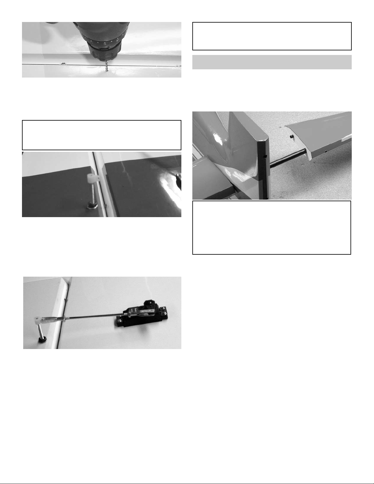
INSTALLING MAIN LANDING GEAR
1. Collect the following items:
(4) 3mm x 15 phillips Head Screw
(4) 3mm Lock Nut
(1) Main Aluminum Landing Gear
2. Remove the landing gear cover from the bot-
tom of the fuselage.
Insert the 3mm x 15 phillips head bolts
through the aluminum mounting brackets on
both sides of the fuselage.
2. Place the landing gear on the fuselage.
Note: the landing gear should curve forward.
Thread the 3mm locking nut on to the bolt and
tighten.
Repeat for the other three bolts
Reinstall the landing gear cover.
WHEEL AND WHEEL PANTS
Collect the following items:
(2) 5-32 x 1-1/4” Axle with Locking Nut
(4) 5/32 Wheel Collars
(4) 4-40 x 1/8” Cup Screws
(4) 4-40 Blind Nuts
(4) 4-40 x 1/2” Button Head Screws
(2) 3-1/4” Wheels
1. Mount the axle to the landing gears.
2. Place the wheel pant onto the axle.
3. Align the bottom of the wheel pant with the
bottom of the landing gear.
4. Mark the hole locations on the wheel pants.
5. Drill 1/8” holes on the marks you just made.
6. Insert the 4-40 blind nuts inside the wheel
pants.
Page 12

12
Wheel Collars
Wheel Pant
Wheel
Landing Gear
7. Mount the wheel pants back on the landing
gear along with the wheel collars and wheels.
8. Center the wheel on the axle.
ENGINE INSTALLATION
1. Collect the following items:
(2) Motor Mounts
(1) Engine
(8) 8-32 x 1-1/4” phillips Head Screw
(4) 8-32 Locking Nut
(8) #8 Washer
(4) 8-32 Blind Nut
2. Place you engine in the mounts and adjust till
the prop drive washer is 5-7/8” from the firewall. Clamp the engine in place and and mark
the location of the mounting holes. Drill using
a 11/64” bit.
Screw the engine onto the motor mount using
the 8-32 x 1-1/4”” screws and locking nuts.
3. Keeping the engine perpendicular to the table
top, clamp the other motor mount to the
engine. Mark and drill the second motor mount
then screw the mount to the engine.
4. Place the motor mount onto the firewall.
Center the motor over the horizontal and ver-
tical lines.
5. Install the motor mount beams on to the fire-
wall plate using the 8-32 x 1-1/4” phillips Head
screws and washers and 8-32 blind nuts
USE THREAD LOCK ON ALL SCREWS
Page 13

13
2. Drill a 1/8” hole in the firewall in position with
the throttle arm. Insert the 1/8” x 16” nylon
tubing in the hole.
Let the tubing exit into the fuselage towards
the throttle servo mount.
Attach the EZ connector to the engine throttle.
Insert the pushrod into the tubing and
through the EZ connector.
ENGINE THROTTLE INSTALLATION
1. Collect the following items:
(1) 1/8” x 16” nylon tubing
(1) .072 x 18” Threaded Rod
(1) EZ connector
(1) Snap Nut
(1) 4-40 x 1/8 Screw
(1) Nylon Snap Link
3. Install the throttle servo.
3. Thread the nylon snap link onto the wire.
Attach the thread link to the servo arm.
Gather the following items
(1) fuel tank
(1) rubber tank stopper
(1) clunk
(1) 3mm x 25mm screw
(1) cap washer large
(1) cap washer small
(2) 3mm x 40mm brass tube
(1) 3mm x 60mm brass tube
(1) silicone tube 4mm x 80mm
(3) silicone tube 5mm x 165mm
1. Insert the 3mm screw through the center hole
in the large washer, through the center hole in
the rubber washer against the large side, and
screw the small washer on the back side.
FUEL TANK ASSEMBLY
Page 14

14
2. Insert the brass tubes through three of the
holes. They should be arranged so as the long
one will be on the right side of the plane and
the short one on the left side.
The tubes should extend out the front of the
cap 5/8”. Bend the long tube up at about a 20
degree angle. This should be adjusted so the
end of the tube almost touches the top of the
tank when installed.
3. Install the 4mm silicone tube to the short
brass tube and install the clunk to the other
end of the silicone tube. This is the fuel pickup and must be free to “flop” around in the
tank so it can pick up fuel in any attitude.
4. Install the assembly into the tank so the vent
tube is turned up to the top of the tank and is
positioned on the right side of the tank.
Tighten the screw to expand the rubber cap.
Don’t over tighten or you could split the tank.
5. Attach the three pieces of 5mm tubing to the
three tank outlets. They are different colors so
you can tell which are the two vents and which
is the fuel pickup after the tank is installed.
Make a note of which color you attach to
which tube. The short brass with the clunk is
the fuel pickup and must go to the carburetor.
One of the long brass tubes is the vent and
should go to the pressure outlet on the muffler.
The second vent can be used for filling the
fuel tank but will have to be plugged with a
screw (Not Included) so that the fuel will not
run out.
INSTALLING THE FUEL TANK
1. Collect the following items:
(1) Fuel Tank
(1) Fuel Line
(4) #2 x 5/16 phillips Head Screw
(1) Wood Hatch Cover
2. Install the fuel tank into the fuselage.
Place some foam around the fuel tank (foam
not included).
Note:
If you are using a engine that needs to pressur-
ize the fuel system then wrap the fuel tank in
string reinforcing tape to prevent splitting when
under pressure.
The tank provided is for glow fuel only.
Page 15

15
3. Place the hatch cover over the motor box.
Drill holes thought the hatch into the ends
of the motor box sides.
Attach the hatch using the #2 x 5/16”
screws.
COWL INSTALLATION
1. Collect the following items:
(1) Cowl
(4) 4-40 x 3/4” Socket Head Bolt
(4) #4 Washer
You will have to remove any parts of the
cowl that rub against the engine. Make
these openings little at first and slowly
make them bigger till the cowl fits over the
engine with out touching. Do not forget to
make an opening for the needle valve and
the fuel lines.
2. Attach the cowl using the 4-40 x 3/4” socket
head bolts and #4 washers.
RECEIVER, BATTERY & SWITCH
Install your radio switch.
Install your receiver and battery pack accord-
ing to your radio instructions.
The Extra 330 has lots of room to move the
battery around to help with the CG. Do not
make a final place till you have balanced the
plane.
We placed our receiver in front of the
rudder servo and our 1200 Mah battery beside
the fuel tank. The location of these items will
vary with the engine used.
1. Gather the following items
(1) Right & Left Wing Panels
(2) 1/4-20 x 1-1/4” Nylon Bolt
(1) Wing Tube
WING BOLTS
Page 16

16
2. Slide the wing tube into one of the wing
halves.
Slide the tube thru the fuselage.
Slide the second wing half onto the wing tube
coming out of the fuselage side.
Push the two wing halves together till they are
tight against the fuselage side.
Bolt the wing to the fuselage using a 1/4-20
nylon bolt.
HATCH & CANOPY
1. Gather the following items
(1) Canopy Hatch
(4) 4-40 x 1/2” Socket Head Bolt
(4) #4 Washer
(1) Canopy
Place wax paper.between the hatch and the
fuselage.
Using the 4-40 x 1/2” bolts and washers,
mount the hatch to the top of the fuselage.
Put in place the canopy over the fuselage
hatch.
Glue in place using canopy glue..
Balancing
Your model should balance at 5-3/4” to
6-3/4” back from the leading edge of the
wing next to the fuselage. For extreme
3D flying you may want to move the CG
back even farther after you are comfortable with the Extra 330. Just remember
that the further back you go the more
sensitive it will become. With extreme
throws the model can get beyond the
ability of novice pilots very quickly.
Start with the controls set at low rate with
the ailerons plus or minus 1/2”, the ele-
vator plus or minus 1” and the rudder
plus or minus 1-1/2”. High rate should be
all you can get.
Good Luck and I hope you enjoy flying
the Extra 330 ARF.
Page 17

17
FLYING YOUR EXTRA 330 ARF
Fully-charged flight batteries
Radio transmitter
1 ½ volt starting battery & glo-plug clip
Fuel bulb or pump
Tools for tightening any parts that can vibrate and
loosen
Paper toweling for clean up
Extra props and an extra spinner
Prop wrench
Bottle of CA glue
FIELD KIT CHECKLIST
PRE-FLIGHT ACTIVITIES
Prior to going to the flying field, with radio batteries
fully charged, turn on both receiver (Rx) and transmitter (Tx) and actuate all controls many times until
you are satisfied with all functions.
Before beginning each day's flying, make a range
check of your equipment in accordance with the manufacturer's instructions. In general, with transmitter
antenna collapsed to 6"-8", you should have an at
least 100 foot range on the ground. To check this,
turn on both the transmitter and the receiver switches, set the model heading away from you, and walk
away while transmitting signals. Watch to see that no
signals are missed until you are at least 100 feet
away. Only if the equipment works perfectly should
any flights be attempted. Again, be careful to not use
your transmitter when anyone else at the field is flying
or testing on the same frequency!
After the range check, stand behind the model and
make sure the control responses are correct. Moving
the control stick to the right should give right aileron
movement up. Moving the stick back or down on the
Tx should move the elevator up, and vice versa.
Check also to see that your wheels operate properly
Your throttle should open to permit full power when
the stick or tab is moved forward or up. Finally, make
sure that everything on your aircraft is neatly and firmly in place-motor fastened down, servos snugged
down, receiver and battery wrapped in foam rubber,
tank properly supported, etc. Prop and spinner must
be tight. The receiver antenna must be extended, not
coiled up inside the model. Nothing should be loose,
or unfinished, or unchecked.
With everything ready, the engine should be started
and broken in for a least a tank or two at no more than
moderate speed. While the engine is running, make
sure the control surfaces do not jitter or move until
you command them and that the throttle also
responds properly to your command.
CGP Super Tote
Page 18

181920
Page 19

Page 20

 Loading...