

Page 1
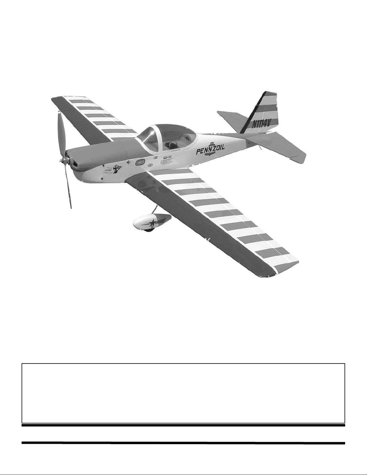
CChhiippmmuunnkk
WARNING
A radio-controlled model is not a toy and is not intended for persons under 16 years old. Keep
this kit out of the reach of younger children, as it contains parts that could be dangerous. A radiocontrolled model is capable of causing serious bodily injury and property damage. It is the buyer's
responsibility to assemble this aircraft correctly and to properly install the motor, radio, and all other
equipment. Test and fly the finished model only in the presence and with the assistance of another
experienced R/C flyer. The model must always be operated and flown using great care and common
sense, as well as in accordance with the Safety Code of the Academy of Model Aeronautics (5151
Memorial Drive, Muncie, IN 47302, 1-800-435-9262). We suggest you join the AMA and become properly insured prior to flying this model. Also, consult with the AMA or your local hobby dealer to find an
experienced instructor in your area. Per the Federal Communications Commission, you are required
to use only those radio frequencies specified "for Model Aircraft."
LIMITED WARRANTY
Carl Goldberg Products, Ltd. has inspected and certified the components of this aircraft. The company urges the buyer to perform
his own inspection, prior to assembly, and to immediately request a replacement of any parts he believes to be defective for their
intended use. The company warrants replacement of any such components, provided the buyer requests such replacement within a period of 10 days from the date of purchase and provided the defective part is returned, if so requested by the company.
No other warranty, expressed or implied, is made by the company with respect to this kit. The buyer acknowledges and understands that it is his responsibility to carefully assemble the finished flying model airplane and to fly it safely. The buyer hereby
assumes full responsibility for the risk and all liability for personal or property damage or injury arising out of the buyer's use of the
components of this kit.
CARL GOLDBERG PRODUCTS, LTD.
P.O. Box 818 Oakwood GA 30566 Phone #678-450-0085 Fax # 770-532-2163 www.carlgoldbergproducts.com
400
Page 2

2
USING THIS INSTRUCTION MANUAL
Before you begin assembling your Chipmunk 400 ARF,
take some time to read through this entire instruction book.
It is designed to take you step-by-step through the process
and to give you added information on motor and radio
selection and set-up, balancing your aircraft, and flying
your model. The time you spend will speed the assembly
process and help you avoid problems.
PREPARING FOR ASSEMBLY
You will need a work area of approximately 24 x 48" which has
been covered to protect it from adhesive, as well as cuts and
other damage. Many people cover their work area with a
sheet of dry wall (sheet rock) and/or waxed paper t o prevent CAGlue and Epoxy from ruining the work surface.
CONSTRUCTION TIPS
IMPORTANT: ALWAYS READ A FEW STEPS AHEAD.
This will alert you to coming instructions and will help you
plan accordingly.
Using the Parts Identification section, familiarize yourself
with the various items included in your kit box.
Do not hesitate to ask questions. Your local hobby dealer
and area flyers will most likely be happy to help, as they
want you to have a successful flying experience.
ADHESIVES & GLUING TECHNIQUES
CA adhesives are specially formulated to firmly glue the
plywood, hardwood, and balsa used in your model and to
withstand the vibration and stresses of high performance
flight. However, there are times, such as when you are
installing the stabilizer and fin on the fuselage and want
more set-up time for careful alignment and positioning,
then you should use epoxy. Occasionally, you also will
want to use thin CA, which "wicks" into the surrounding
areas. Aliphatic resin glue or similar water-based glues can
also be used, but they will add to the assembly time
because they dry so much more slowly than CA glue.
Remember, when ever using any CA, you must be careful
to read instructions thoroughly, as you will have only seconds for positioning of parts. Be sure to trial fit parts
together before gluing. Also, never use watery THIN type
CA glue for gluing plywood and hardwood parts. Thin CA's
do not adequately bond these areas.
CAUTION
Some people may experience an allergic reaction when
exposed to fumes from CA glue or epoxy. As with paints,
thinners, and solvents, it is always important to use glues
only where there is adequate ventilation to carry fumes
away. A fan is recommended. Also, special care must be
taken when using CA, as it will bond skin as well as other
surfaces. Before using any CA, carefully read all label precautions. When using CA, protective eye-wear and care in
keeping the glue away from the face is highly recommended. If CA does happen to get into the eye, hold lid open
and flush with water only. Seek immediate medical attention.
COVERING
The Chipmunk 400 ARF is covered in a polyester film chosen for its beauty, toughness, and ease of application and
repair. It is not uncommon for ARF's to develop a few wrinkles in transit. If this is true of your model, the situation is
easily corrected. Before you begin putting the pieces
together, run around the edge of the seams first then over
the surface of each section with an iron (either specially
designed for airplane use or the more cumbersome household iron). Apply the heat (set at about 350° F), following
along with a soft cloth and pressing down on the covering
as you go around. This will more firmly set the covering
adhesive into the wood and keep your aircraft covering
tight and smooth in the future. Once you have ironed the
seams stay away from them with the heat or the covering
will slide when you try to shrink the middle. If this happens
the wrinkles will not come out of the covering.
One of the great advantages of polyester film is that it can
be applied over itself without causing gas bubbles. This
allows you to repair your aircraft, as well as to customize it
in a number of ways. If, due to a flight mishap, you get a
hole or similar covering damage, simply trim away the
ragged edges and then apply a patch, following the directions that come with your covering , which is available at
your hobby dealer.
The Chipmunk 400 covering can be closely
matched using
Oracover Flame Red
Oracover White
Oracover Midnight Blue
Page 3

3
ITEMS NEEDED TO COMPLETE THIS AIRCRAFT
1 4 CHANNEL RADIO WITH 4 MICRO SER-
VOS. (WE USED 4 CHANNEL FUTABA
RADIO WITH S3108 SERVOS AND GREAT
PLANES ELECTRIFLY RECEIVER W/O
SPEED CONTROL)
1 6” SERVO “Y” HARNESS
2 6” SERVO EXTENSIONS
1 ELECTRONIC SPEED CONTROL (WE
USED A CASTLE CREATIONS PHOENIX
25 BRUSHLESS SPEED CONTROL)
1 3 CELL LI-PO BATTERY (GREAT PLANES
ELECTRIFLY 1500)
1 ULTRAFLY BRUSHLESS MOTOR A/30/29
WITH 3.89 GEAR RATIO
1 GREAT PLANES ELECTRIFLY PROP
ADAPTER 3MM APC LONG
1 APC PROPELLER 9 X4.7 SLO FLYER
1 CA ACCELERATOR
1 1 OZ. BOTTLE CA MEDIUM GLUE
1 1/2 OZ. BOTTLE CA THIN GLUE
1 5 MINUET EPOXY
1 1/4” FOAM RUBBER
1 #2 X 1/4” SHEET METAL SCREW FOR
MOTOR(MIGHT BE REQUIRED FOR SOME
MOTOR INSTALLATIONS)
TOOLS AND SUPPLIES FOR ASSEMBLY.
MODELING OR UTILITY KNIFE
WORK SURFACE (24" X48")
SMALL STANDARD & PHILLIPS SCREW-
DRIVERS
MASKING TAPE
NEEDLE NOSE PLIERS
24” RULER
FLEXIBLE STRAIGHT-EDGE
30-60-90° x 6" TRIANGLE
SOFT PENCIL
A FEW STRAIGHT OR "T" PINS
WIRE CUTTER (DYKES)
OPTIONAL HEAT GUN/COVERING IRON
ACID BRUSH
5 FT. LENGTH OF STRING
Caution:
Before starting, care-
fully go over all high
stress areas (Wing
bolt mounting blocks,
Firewall,etc.) with an
epoxy or wood glue to
confirm all areas are
well glued.
Page 4
4
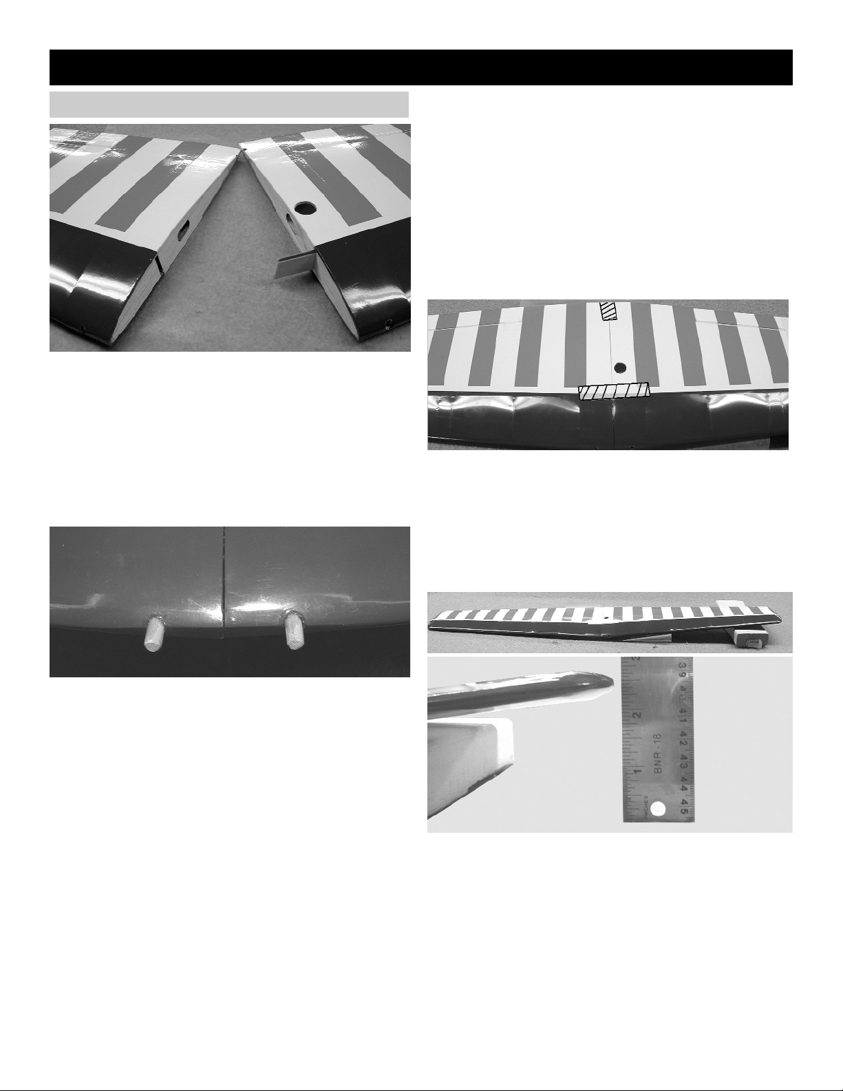
Wing
JOINING THE WING
1. Collect the following items:
(1) Right wing
(1) Left wing
(1) Wing joiners
(2) 5mm x 17 dowel
A book or block of wood
NOTE: If the covering on your wing has loosened in
transit, refer to the covering section of the
INTRODUCTION before continuing.
2. Insert the wing joiner with the angle cut facing
up, into the joiner pockets in both wing halves.
The joiners should fit easily in the pockets and
the wing halves should meet in the middle,
with the wing dihedral forming a broad "V".
Trial fit the wing dowel in the hole, as shown
above. When satisfied with the fit of the dowel
and the joiners, remove them from the wing
pockets.
3.
Working on a protected surface, and with a
paper towel handy for cleaning fingers,
THOROUGHLY mix 1-2 large (soup) spoons
each from bottle A and bottle B of Epoxy. (Use
equal amount of each part and mix with a stick
in a plastic or paper cup, or on a sheet of
waxed paper.)
Spread epoxy on the joiner
Put additional epoxy in the joiner pockets and
in the dowel hole and spread a thin layer of
epoxy along one side of the entire center joint
area. Immediately proceed to the next step.
4.
Working rapidly, so that the epoxy does not set
before you are finished, slide the wing joiner
into one wing pocket.
Slide the dowels into the dowel holes. Then
slide the wing halves together until they are
touching.
5. With masking tape, tape the wing halves
together at the trailing edge and close to the
leading edge, as shown. This will help keep
the wing from twisting.
Place additional tape at several locations
across the center seam of the wing, so that the
halves stay firmly together while the epoxy
sets.
NOTE: When one wing half is flat on the table, the
wing dihedral will force the other side of the wing up
about 2-1/2" off the table. Place a book or a block of
wood under the high side to support the wing and keep
the halves in proper position. Caution: Do not distort
the wing by blocking it too high or too low, and do
not touch the assembly until the epoxy dries.
Page 5

5
Installing Ailerons
1. Collect the following parts:
(1) Wing
(2) Ailerons ( Left & Right)
(6) Mini CA hinges
1. Locate the pre-cut aileron hinge slots in both
sides of the wing. Using a hobby knife (#11
blade), slide the blade into each slot to make
sure it is cleanly cut.
Repeat this process with the ailerons, making
sure all hinge slots are clean.
2. Find the control horn slot near one end of the
aileron.
Align the slot in the aileron with the servo hole
in the wing.
Insert the mini CA hinges half way into the
wing and the ailerons. (Use a pin inserted into
the middle of the hinge to help keep the hinge
in the middle.)
Make sure that the aileron is tight against the
wing and even with the wing tip.
Using thin CA glue, place one drop on all
hinges top and bottom.
1. Gather the following items:
(2) 6" Extension wires
(1) Wing
(2) Servos
(1) Electrical tape
2. Plug one 6" extension wire into one servo.
IMPORTANT! To ensure that any connections located
inside the wing will not come loose, either when the
wires are pulled, or during flying, always tape them
securely together with electrical tape.
3. Tie the wheel collar to the end of the string.
Insert the wheel collar through the servo
opening in the wing.
Allow the wheel collar to fall through the wing
till it can be pulled out through the hole in the
center of the wing.
Aileron Servo Extensions
4. Tie or tape the other end of the string to the
servo extension.
Page 6

6
2. Remove the covering on the aileron where
the control horn sits.
Using CA glue, attach the control horn to the
aileron.
4. Find the small aileron pushrod wire, and place
a “z” in one end.
Connect the pushrod connector to the servo
arm.
Put the “Z” bend in to the top hole of the con-
trol horn.
Slide the pushrod wire through the connector
on the servo arm and mount the arm on to the
servo.
Tighten the set screw onto the pushrod.
5. Repeat for the other aileron pushrod.
Aileron Control Horns
1. Collect the following parts:
(1) Wing
(2) Control Horns
(2) EZ connectors with screws and nylon nuts.
(2) Pushrod Wires
Push the extension in the servo hole, SLOW-
LY pull until the end of the 6" extension comes
out of the hole in the center of the wing.
Tape the extension securely to the wing, so
that it will not slide back in while you are working.
Mount the aileron servo using the hardware
provided by the radio manufacture.
5. Repeat steps 2 thru 4 for the other aileron
servo.
Fuselage Hatch
1. Collect the following parts:
(1) Fuselage
Hatch Pin
2. Pull Out on the hatch pin.
Lift up on the rear of the canopy.
Hatch post
3. Remove the hatch off the front hatch post.
Page 7

7
Stabilizer
1. Collect the following parts:
(1) Fuselage
(1) Stabilizer & Elevator
(1) wing
(1) 4-40 x 1/2” Socket Head Bolt
(1) Wooden Washer covered in red
2. Locate the hole in the center of the wing for
the wing bolt. Remove the covering over the
hole.
Mount the wing to the fuselage using the bolt
and wooden washer.
Make an out line of where the wooden wash-
er rest on the wing.
Remove the covering on the wing where the
wooden washer will rest.
Glue the wooden washer to the wing.
3. Find the center of the stabilizer, by measuring
the length of the trailing edge where the elevator hinge line is located.
Stand the stabilizer up on its edge and using a
right triangle draw a center line up from the
trailing edge to the leading edge.
Find the center of the fuselage in front of
where the stabilizer sits.
Place the stabilizer on the fuselage using the
marks you just made.
“X”
“X”
4. Measure from the end of the wing to the tip of
the stab. This measurement should be the
same for both sides.
Mark the stabilizer where it rest on the fuse-
lage
Remove the covering where the stab will be
glued to the fuselage.
Look down the length of the fuselage and
check that the stabilizer is parallel to the wing.
If it is not then shim the low side till they are
parallel.
When satisfied then glue the stabilizer in place
using 5 minuet epoxy. Make sure the stabilizer remains both perpendicular and parallel to
the wing and fuselage while the epoxy dries.
2. Remove the balsa wood plug at the rear of the
fuselage where the stabilizer mounts.
Elevator Installation
1. Collect the following parts:
(1) Fuselage With Stabilizer
(2) Elevator
(4) Mini CA Hinges
(1) Nylon Control Horn
(1) Long Pushrod Wire
2. Locate the slot in one side of the elevators
near the center.
Remove the covering over the slot.
Bottom of Elevator
Page 8

8
3. Insert the mini hinges into the slots in the ele-
vator.
Take the long wire pushrod and insert the “Z”
bend end into the outer hole of the control
horn.
Insert the wire into the hole in the side of the
fuselage.
Push the elevator forward and insert the
hinges into the stabilizer. (use pins to keep the
hinges centered)
Glue the hinges in place same as you did the
aileron.
Fin & Rudder Installation
1. Collect the following parts:
(1) Fuselage With Stabilizer
(2) Fin & Rudder
(2) Mini CA Hinges
(1) Nylon Control Horn
(1) Long Pushrod Wire
Glue the Nylon control horn into the slot mak-
ing sure that the elevator is placed on the
work bench as shown in the previous photo.
3. Insert the fin into the fuselage slot.
Mark where the fuselage meets the fin.
Remove the fin from the fuselage.
Carefully cut the covering off the fin where the
fin will be glued to the fuselage.
Remove the rudder from the fin and glue the
fin to the fuselage making sure to keep the fin
perpendicular to the stabilizer.
2. Locate the slot in the rudder near the bottom.
Remove the covering over the slot.
Glue the Nylon control horn into the slot mak-
ing sure that the rudder is placed on the work
bench as shown above.
3. Insert the mini hinges into the slots in the rud-
der.
Take the long wire pushrod and insert the “Z”
bend end into the outer of the control horn.
Insert the wire into the hole in the top of the
fuselage next to the fin.
Push the rudder forward and insert the hinges
into the fin. (use pins to keep the hinges centered)
Glue the hinges in place.
Page 9

9
Landing Gear
1. Collect the following parts:
(1) wing
(2) Main Landing Gear Wire
(4) 2mm x 6 Sheet Metal Screw
2. Remove any covering over the landing gear
slot.
Insert the short end of the main landing gear
wire into the hole.
Locate the two holes next to the landing gear
slot.
Screw the landing gear into place using two
2mm x 6 Sheet Metal Screws.
Fuselage
Wheel Pants
1. Collect the following parts:
(1) wing
(2) Wheel Pants
(2) Wheel Collars with set screws
(4) 2mm x 3mm Sheet Metal Screw
(2) Landing gear strap
(2) Wheels
Landing gear Wire
Wheel Pant
Wheel
Wheel Collar
Landing Gear Strap
2mm x 3mm Sheet Metal Screw
2. Place the wire though the back side of the
wheel pants.
Insert the wheel into the wheel pant.
Push the landing gear wire through the wheel
and out the other side of the wheel pant.
Insert the wheel collar on the end of the land-
ing gear wire.
While slightly squeezing the wheel pant tight-
en the wheel collar onto the landing gear wire.
3. Place the landing gear strap onto the landing
gear wire so that the slot in the strap fits over
the wire.
Screw the strap to the wheel pant using the
2mm x 3 sheet metal screws.
Repeat steps 2 & 3 for the other wheel pant.
Page 10

10
Tail Wire
1. Collect the following parts:
(1) Fuselage
(1) Tail Skid Wire
(1) 2mm x 3mm Sheet Metal Screw
2. Insert the end of the tail skid wire into the fuse-
lage.
Screw the wire to the fuselage using the 2mm
x 3mm Sheet Metal Screw.
Installing Motor & ESC
1. Collect the following parts:
(1) Fuselage
(1) Motor with Gear Drive (Not Included)
(1) Electronic Speed Control (Not Included)
(1) Screw for motor installation (Not Included)
Note:
Read the instructions that come with your
motor and speed control for proper wiring.
Your Motor and Speed Control might be dif-
ferent than shown.
2. We have assembled the motor and gear drive
that was provided with the Ultrafly system by
the manufactures instructions.
Slide the gear drive onto the motor stick till the
rear of the prop drive is 2-3/4 away from the
firewall.
Screw the gear drive to the motor stick.
2-2/3”
Caution:
Do Not install the propeller at this time.
Electric motors can start turning at any time
during radio installation. This can cause
damage to the plane or bodily harm.
Installing Cowl
1. Collect the following parts:
(1) Fuselage
(1) Cowl
(4) #2mm x 5 Screws
2. Center the prop shaft in the opening of the
cowl.
Screw the cowl to the side of the fuselage
using the #2mm x 5 screws.
Caution:
Do not over tighten the screws. Use CA glue
in the screw holes of the fuselage to
strengthen the wood.
Page 11

11
2. Mount the elevator and rudder servo as
shown above.
Attach the EZ connectors to the servo arms
the same way you did the aileron servos.
Insert the pushrod wires through the EZ con-
nectors and mount the two servo arms to the
top of the servos.
Cut off the excess pushrod wire.
Radio Installation
1. Collect the following parts:
(1) Fuselage
(2) Micro Servos with Hardware (Not Included)
(1) Micro Receiver (Not Included)
(1) Servo “Y” Harness (Not Included)
(2) Mini- Pushrod Connectors
Rudder
3. Plug the elevator and rudder servos into your
receiver.
Attach the “Y” harness to the receiver.
Plug in the speed control.
Cut foam and wrap around the receiver.
4. Put the receiver wrapped in foam in front of
the servos.
1. Collect the following parts:
(1) Fuselage
(1) Wing
(1) 4-40 x 3/4 Socket head bolt
(1) 3 cell Li-Po Battery
Battery Installation
2. Mount the wing to the fuselage.
Look down through the fuselage hatch and
make sure all the radio wires are not pinched
between the fuselage and the wing.
Insert foam into the front battery compart-
ment.
Slide the Li-Po battery into the front compart-
ment.
Page 12

12
Balancing
Your model should balance 2-1/2” back from the leading edge of
the wing next to the fuselage.
Control Set Up
Turn on your transmitter and plug in the receiver
battery. Center all the control surfaces (rudder,
elevator & aileron). If required by your speed
control this is the time to program it for your
use.
Control Travel
Aileron up / down 1/2”
Elevator up / down 3/4”
Rudder Right / Left 1”
Propeller
Install the prop adapter and your propeller at
this time. We used a 9 x 4.7 APC prop for our
motor, battery and speed control setup.
Caution:
The propeller can start turning any
time the receiver battery is plugged
in.
Decal Locations
1. Using glass cleaner and a soft cloth, clean the model surface thoroughly before applying decals.
Cut the decal sheets apart in sections, as needed.
Peel the backing off the decal and apply the decal to the plane.
 Loading...