

Page 1

When it was introduced, the outstanding Russian SUKHOI took the aerobatic world by storm! Never before have
aerobatic enthusiasts had a machine so capable that it appears to have no limits. It enables the pilot not only to execute maneuvers with exceptional precision, but allows him to invent new maneuvers, as well! We have so completely
captured the essence of this extraordinary, competition-worthy aircraft that any good sport flyer will be able to experience the thrill of true unlimited aerobatics with his GOLDBERG SUKHOI. IMPORTANT: When selecting a power
plant for your SU-26, do not put in a larger-than-recommended engine. This will cause undo stress to the airframe
and may result in structural failure. Remember, a bigger engine does not necessarily mean better performance.
WARNING! THIS IS NOT A TOY!
A radio-controlled model is not a toy and is not intended for persons under 16 years old. Keep this kit out of the
reach of younger children, as it contains parts that could be dangerous. A radio-controlled model is capable of causing serious bodily injury and property damage. It is the buyer's responsibility to build this kit correctly and to properly install the motor, radio, and all other equipment. Test and fly the finished model only in the presence and with the
assistance of another experienced R/C flyer. The model must always be operated and flown using great care and
common sense, as well as in accordance with the safety standards of the Academy of Model Aeronautics (5151
Memorial Drive, Muncie, IN 47302, 1-800-435-9262). We suggest you join the AMA and become properly insured
prior to flying this model. Also, consult with the AMA or your local hobby dealer to find an experienced instructor in
your area. Per the Federal Communications Commission, you are required to use only those radio frequencies specified "for Model Aircraft."
LIMI TED WARRANTY
Carl Goldberg Products takes pride in the care and attention given to the manufacture of components for its model airplane kits. The
company warrants replacement of any materials found to be defective for their intended use, prior to their use in construction of the aircraft, provided the buyer requests such replacement within one year from the date of purchase and provided the defective part is
returned, if so requested by the company.
No other warranty, expressed or implied, is made by the company with respect to this kit. The buyer acknowledges and understands
that it is his responsibility to carefully construct a finished flying model airplane and to fly it safely. The buyer hereby assumes full responsibility for the risk and all liability for personal or property damage or injury arising out of the buyer's use of the components of this kit.
Pt. #2097 2/03
INSTRUCTIONS
SUKHOI SU-26
©Copyright 1993
Page 2

ITEMS NEEDED TO COMPLETE THIS KIT
1 RADIO GUIDANCE SYSTEM (4 CHANNEL MINIMUM REQUIRED)
1 ENGINE .90 2-CYCLE OR 1.20 4-CYCLE
(NO BIGGER!)
1 PROPELLER (SIZE DEPENDS ON
ENGINE)
1 12-16 OZ. FUEL TANK
1 12" SILICONE FUEL LINE
2 3-1/2" DIAMETER WHEELS
1 1-1/4" DIAMETER WHEEL
3 ROLLS IRON ON COVERING FLIM
1 CGP 3" DIAMETER SPINNER
3 2 OZ. BOTTLE CA GLUE
1 EPOXY 6 OR EPOXY 20 MINUTE
1 TUB JET MODEL MATE
1 CGP 1/4" FOAM PADDING
4 CGP 3/16" WHEEL COLLAR
1 TUBE CLEAR CANOPY GLUE
1 CGP 3/32" WHEEL COLLAR
OPTIONAL
PILOT: 1/5 SCALE
TOOLS AND SUPPLIES
REQUIRED FOR ASSEMBLY
MISCELLANEOUS RUBBER BANDS
(INCLUDING #64)
ROLL OF WAXED PAPER
SANDPAPER (ASSORTED GRITS, INCLUD-
ING COARSE (80), MEDIUM (150) AND
FINE (220)
SANDING BLOCK
"T" PINS (at least 100)
X-ACTO MODELING KNIFE
SINGLE EDGE RAZOR BLADE
RAZOR SAW
BUILDING BOARD (24" x 74")
36" STEEL STRAIGHT EDGE
ELECTRIC DRILL
1/8" DRILL BIT
5/16" DRILL BIT
5/32" DRILL BIT
SMALL SCREWDRIVER
SOLDERING IRON AND FLUX
COVERING IRON AND HEAT GUN
MASKING TAPE
6" RULER
10" 30-60-90 DRAFTING TRIANGLE
SPRAY BOTTLE
2
Page 3

INTRODUCTION
USING THIS INSTRUCTION MANUAL
Before you start gluing and sanding, take some time
becoming familiar with the plans and looking through this
entire Instruction Booklet. It is designed to guide you
through the construction process step by step, so build in
the order given in this book. Building options, as well as
balancing, set- up, and flying the model are covered.
Like a full-size airplane, the SUKHOI is built from
basic structures (stabilizer, fin, wing, etc.), which are then
assembled into the complete airplane.
Special procedures or comments will usually be
explained before a step, so you will be prepared. If a step
begins with a statement like "Note," "Warning," or
"Important," it is a good idea to read through the step
before doing it.
A check-off box appears at the beginning of each
step. Check these boxes as you build, so you can tell at
a glance what steps you have completed. Some steps
are repeated and must be marked twice, as in the case of
the left and right wing panel.
Some of the instructions deal with general procedures. Boxes are not needed for these sections.
HOW TO READ THE PLAN
There are two plan sheets in this kit, showing the
Fuselage (Body), the Wing, and the Tail Parts.
Everything on the plan is drawn to full-size and shape and
shows how the finished parts fit together.
The plan is drawn to show the model completely
assembled, but as a result, the areas inside or underneath are covered up, making it hard to understand how
these parts fit together. Therefore, for clarity, some parts
are drawn with hidden lines, others with breakaway
views, and some are entirely removed from the structure
and shown separately.
For example, on the fuselage, the left side of the completed model has been removed to show the details
inside. Sometimes a surface is broken away to reveal the
detail behind or underneath. Dashed lines indicate details
that are hidden behind or under another part of the surface.
The model is made from four varieties of wood: balsa,
bass, birch, and various plywoods. Each kind of wood
has its own characteristic end grain pattern (as viewed
from the end) which has been drawn in this book. You
can easily use these end grain patterns to identify what
kind of wood is shown for a part, if you are in doubt.
HOW TO USE THE PLAN
The plan is used in several ways. The wings, stabilizer,
and fin are assembled directly over the plan. Each wood
part is matched over its corresponding location printed on
the plan and pinned in place. To prevent ruining your plan
from gluing your wings, etc. to it, cover the area you are
working on with waxed paper.
The paper the plan is printed on can expand or
contract slightly with changes in temperature or
humidity. Because of this, a preformed part such as
the notched wing trailing edge may not exactly match
the plan. This is no problem, as slight deviations in the
outline or size will not noticeably affect flight performance.
Because the fuselage plugs together and is selfaligning, it is not built directly over the plan. As you
assemble the fuselage, you will find the plan helpful in
identifying parts and how things fit together. The plan
also shows the installation of a typical radio, battery and
all remaining equipment and hardware needed to complete the model. By referring to the examples shown,
you should be able to install your own radio, etc., even if
it is not the same as what is shown on the plan.
IDENTIFYING PARTS
Parts for the wing are bundled together; likewise, parts
for the tail assembly are also grouped. Die-cut plywood and
balsa sheets of common sizes are bundled together, so they
are less likely to be damaged during shipping and handling.
The various screws, hinges, and fittings are packaged
in plastic bags.
PREPARING FOR ASSEMBLY
Set a flat, warp-free pinning board on your work
bench. Any material that accepts pins, such as insulation
board, soft plywood, or dry-wall (sheet rock) will work.
Important: any warps or bends in the pinning board will
result in wings or tail surfaces that are also warped or
bent, making your model more difficult to fly. Make sure
that the pinning board is flat by laying a straight edge
across it. You may be able to correct a warped board by
shimming its low areas.
Position the area of the plan (such as the stabilizer)
on which you are going to build over the pinning board
and tape it in place so the plan lays flat and wrinkle free.
Place a sheet of waxed paper or plastic kitchen wrap
over the work area to prevent Super Jet from sticking to
your plan and ruining it.
CONSTRUCTION TIPS
In assembling your model, the following tips will
prove helpful.
IMPORTANT: ALWAYS READ A FEW STEPS
AHEAD. This will alert you to coming instructions and
will help you plan accordingly.
You may find it convenient to empty all of the small
parts from the hardware bags into a common container,
such as a margarine tub. This will help you find items
quickly.
When drilling any 1/16" holes in balsa, you may find
it easier to twist the drill between your thumb and index
finger. This procedure allows more control in positioning
the drill on the center mark.
Punch out only the laser-cut parts you need as you
proceed. This will help you keep track of parts, especially the small ones.
Sometimes you will be asked to “tack cement” a
piece of wood that will later be taken apart. To provide
for easy removal without damage, use only a small drop
of glue.
After completing each section of the aircraft, you may
want to go back and reglue the joints, just in case some
area has been missed. Be careful not to use too little
glue, which will leave the model weak, or too much glue,
which can make the model heavy. Properly glued joints
are important to the overall strength of the model. CA
glue is recommended for most parts of the assembly,
although epoxy glue may be used when more time is
needed for careful placement.
3
Page 4
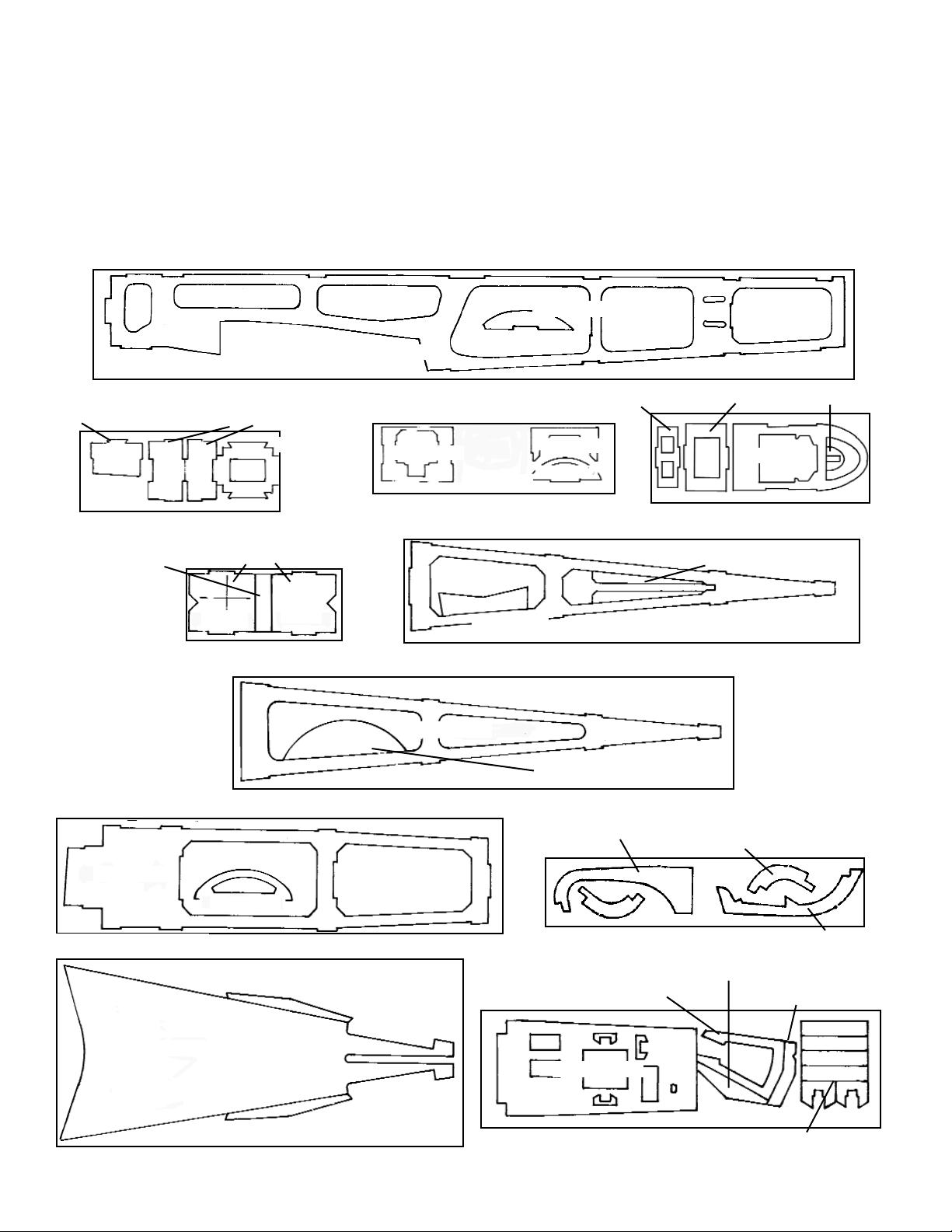
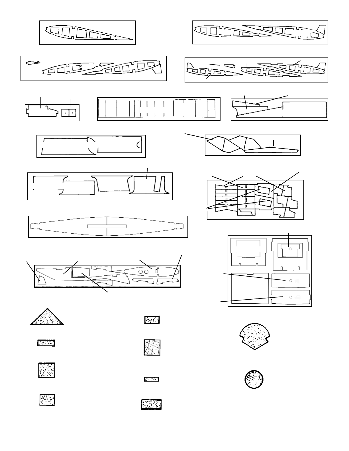
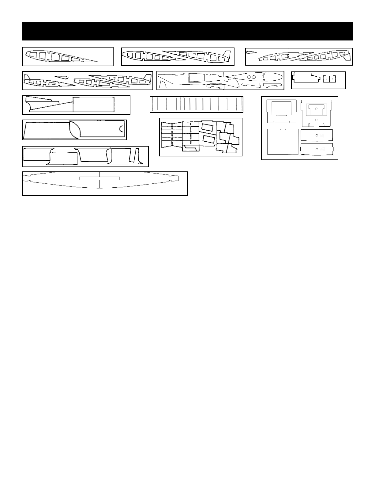
WOOD PARTS
Be careful when removing parts (such as fuselage formers) from the laser-cut sheets. Long parts are fragile
until glued into a structural unit. If necessary, use a
razor knife or razor saw to assist in the removal of
parts from the sheet. Sometimes a little trimming and
sanding can improve parts, where desired. Save scrap
until the model is completed, in case a part is missing
or damaged. Also, scrap is used in some building
steps.
ABOUT THE WOOD IN THE KIT
We strive to supply good quality materials in your kit.
Wood parts are inspected with regard to the function
they will serve. If an imperfection is spotted in a scrap
corner of a laser-cut sheet and doesn't affect actual
parts, the sheet is considered acceptable. Also, internal stresses in wood are relieved as it is cut into parts.
These relieved stresses may cause some parts to
bow. Bows in wood parts (such as leading edges)
readily straighten out as they are CA glued into a
structural unit
4
D/C SHT. 6728 2 REQ’D
D/C SHT. 6703 1 REQ’D
D/C SHT. 6704 1 REQ’D
D/C SHT. 6705 1 REQ’D
WING PIN
DOUBLER
D/C SHT. 6707 1 REQ’D
D/C SHT. 6708 1 REQ’D
D/C SHT. 6709 1 REQ’D
D/C SHT. 6710 1 REQ’D
D/C SHT. 6712 1 REQ’D
D/C SHT. 6711 2 REQ’D
D/C SHT. 6706 1 REQ’D
MOTOR MOUNT SIDES
FUSELAGE SIDE
FORMER H
FORMER JFORMER G
TANK TRAY
COWL SIDE SUPPORT
WIND STOP
FRONT
BACK
FORMER E
FORMER E
FORMER C
FORMER D
TOP FRONT
TURTLEDECK
RUDDER BOTTOM
RUDDER TOP
SERVO TRAY
RUDDER GAUGE
AILERON GAUGE
ELEVATOR GAUGE
ROUNDING TOOL PARTS
ELEVATOR AIRBALANCE L.E.
COWL SUPPORT-TOP
BOTTOM AFT
TOP AFT
FIREWALL
MOTOR MOUNT FRONT
TURTLEDECK BACK-UP
FORMER F
Page 5
5
D/C SHT. 6720 4 REQ’D
L/C SHT. 6730 1 REQ’D
D/C SHT. 6723 1 REQ’D
D/C SHT. 6722 2 REQ’D
D/C SHT. 6727 1 REQ’D
L/C SHT. 6731 2 REQ’D
L/C SHT. 6732 1 REQ’D
D/C SHT. 6719 4 REQ’D
D/C SHT. 6718 2 REQ’D
D/C SHT. 6726 1 REQ’D
D/C SHT. 6716 2 REQ’D
D/C SHT. 6715 2 REQ’D
D/C SHT. 6714 2 REQ’D
RIB #2
LANDING GEAR DOUBLER
L. G. COVER
PLATE
WING CENTER DOUBLER
WING DOWEL SCAB PLATE
FORMER B
FORMER B2
WING SADDLE DOUBLER
CENTER RIB
WING JOINER
FRONT
WING JOINER
REAR
RIB #2 TEM-
PORARY TAB
STAB JOINER
ELEVATOR HORN MOUNT
AILERON HORN BACK-UP
AILERON SERVO
MOUNT
BEVEL GAUGE
DIHEDRAL FIXTURE
AILERON COVER SHEET
CENTER SHEET
RIB SPACER
GAUGE
TIP SHEET
SHEAR WEB
WING BOLT PAD
WING CENTER SHEETING
WING TIP SHEETING
AILERON SERVO SHEETING
AILERON RIB
AILERON RIB
RIB #6
RIB #7
RIB #5
RIB #4
RIB #8
RIB #9
RIB #10
RIB #3
D/C SHT. 6725 2 REQ’D
1/2” BALSA TRI
STOCK 3 REQ’D
5/16 x 3/8 x 14”
BALSA 1 REQ’D
1/8 x 3/8 x 12”
BALSA 4 REQ’D
1/4 x 5/16 BALSA
12” 1 REQ’D
16” 2 REQ’D
24” 3 REQ’D
3/16 x 3/8 x 20”
BALSA 2 REQ’D
SHAPED L.E. x 36”
2 REQ’D
5/16 DIA. x 4-1/2”
DOWEL 1 REQ’D
3/8 SQ. BASS
12” 8 REQ’D
15” 1 REQ’D
18” 4 REQ’D
35-1/8” 4 REQ’D
5/64 x 1/4 x 22”
BALSA 5 REQ’D
1/8 x 1/4 BALSA
20” 3 REQ’D
36” 4 REQ’D
Page 6
TAIL CONSTRUCTION
1. Collect the following items:
(1) D/C SHT. 6711 BALSA PT. # 3670
CONTAINS:
(4) ELEVATOR AIR BALANCE L.E.
(2) RUDDER BOTTOM
(2) RUDDER TOP
(1) D/C SHT. 6712 PLY PT. #3671
CONTAINS ROUNDING TOOL
(1) D/C SHT. 6727 BALSA PT. #3657
CONTAINS:
(1) STAB JOINER
(4) ELEVATOR HORN MOUNT
(1) D/C SHT. 6723 PLY PT. #3697
CONTAINS BEVEL TOOL
(1) D/C SHT. 6710 PLY PT. #3669
CONTAINS:
(2) STAB JOINER DOUBLER
(3) TRUSSING STICKS PT. #3675
1/4 x 1/8 x 20” BALSA
(4) RUDDER TRUSSING PT. #3676
1/8 x 3/8 x 12” BALSA
(1) STAB T.E. DOUBLER PT. #3677
1/4 x 5/16 x 12” BALSA
(2) STAB L.E. & TIP PT. #3678
1/4 x 5/16 x 16” BALSA
(3) PERIMETER STICKS PT. #3679
1/4 x 5/16 x 24” BALSA
(2) ELEVATOR TRUSSING PT. #3680
3/16 x 3/8 x 20” BALSA
(1) RUDDER TRAILING EDGE PT. #3681
5/16 x 3/8 x 20” BALSA
(8) ELEVATOR PERIMETER STICK PT. #3682
3/8” SQ. x 12” BALSA
(1) RUDDER LEADING EDGE PT. #3683
3/8” SQ. x 18” BALSA
(1) STAB PLATFORM PT. #3684
1/4 x 2-1/2 x 3-3/4” BALSA
(4) STAB/FIN SHEETING PT. #3685
5/64 x 3 x 24” BALSA
(2) FIN SHEETING PT. #3686
5/64 x 3 x 18” BALSA
(1) CENTERLINE MARKING TOOL PT. #1425
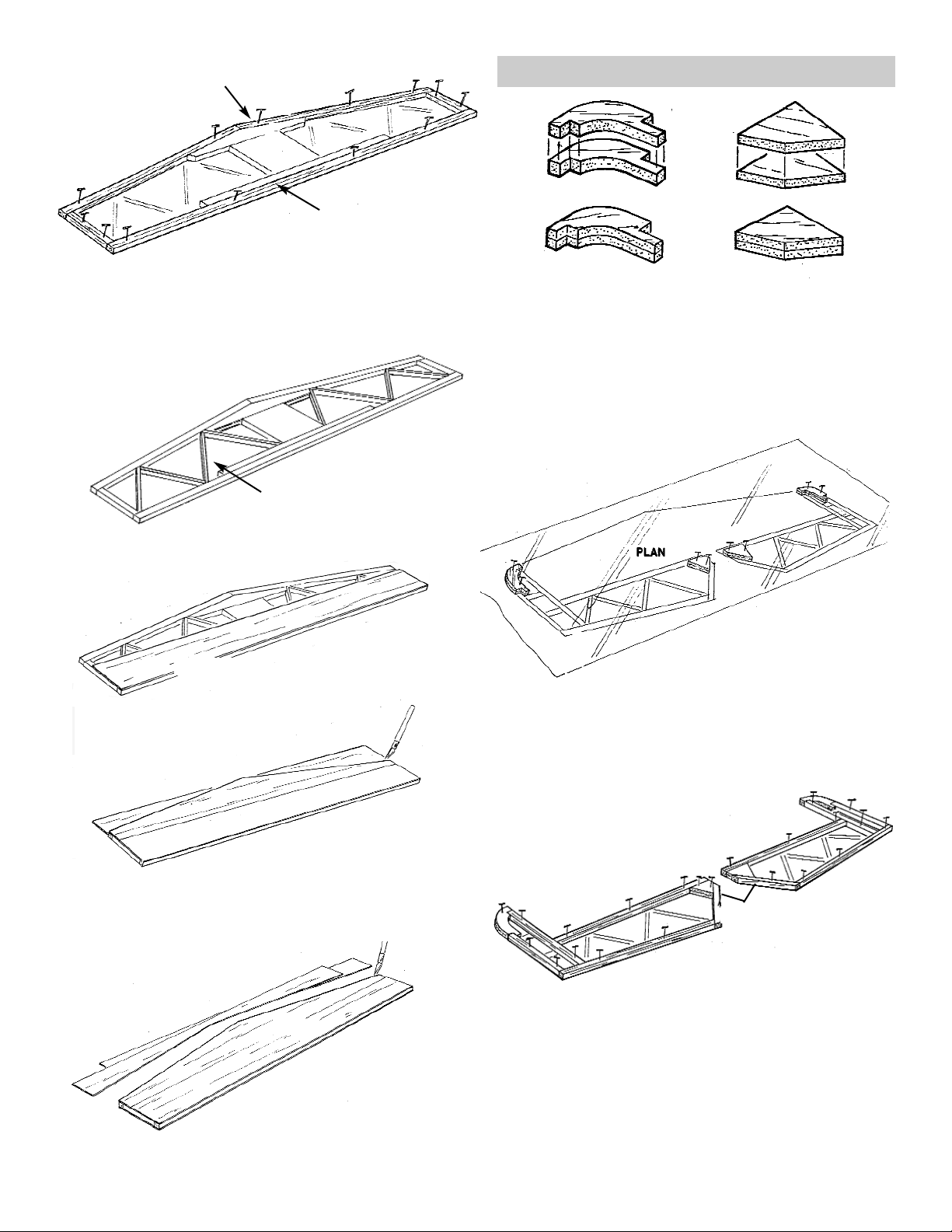
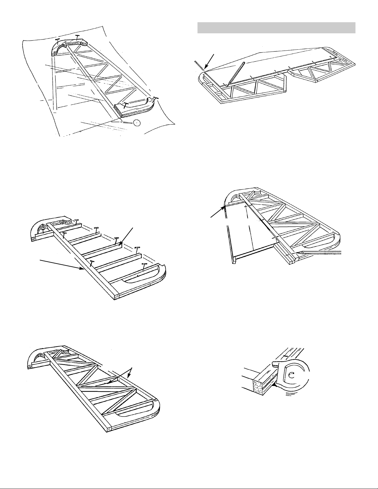
HORIZONTAL STABILIZER
2. Place the WING PLAN on the building board
and cover the horizontal stabilizer portion of
the plan with waxed paper.
3. Glue a STAB JOINER DOUBLERS to each
side of the STAB JOINER, as shown above.
4. Glue and pin the JOINER ASSEMBLY, STAB
PLATFORM and T.E. DOUBLER over the plan.
(10) LARGE FLEX POINT HINGE PT. #1449
(1) WING PLAN PT. #2124
(1) FUSELAGE PLAN PT. #2123
6
3/16" BALSA
1/32" PLY
PLAN
1/4 x 2-1/2 x 3-3/4" BALSA
1/4 x 5/16 x 12"
Page 7
7. Trimming as needed, prefit the SHEETING
onto the stab. When satisfied with the fit, CA
glue in place.
8. Flip the stab over and sheet the other side.
ELEVATOR
1. Laminate the two sets of ELEVATOR AIR BAL-
ANCE L.E.s and ELEVATOR HORN MOUNTS.
2. Place waxed paper over the elevator portion of
the plan.
3. Working over the plan, glue and pin the ELE-
VATOR AIR BALANCE L.E.s and the ELEVATOR HORN MOUNTS in place.
4. Trim each PERIMETER STICK, as needed,
and glue and pin in place over the plan.
6. Trim and glue the TRUSSING in place.
5. Trim the STAB LEADING EDGES and TIPS to
fit.
Pin in place and glue.
7
1/4 x 5/16 x 16"
1/4 x 5/16x24"
1/8 x 1/4 x 20"
3/8" SQ. BALSA
5/64” BALSA
Page 8

6. From scrap 3/16” balsa, cut a piece 1/2”x 1/2”
triangle to form a gusset.
Glue in place, as shown.
VERTICAL FIN
RUDDER
1. After covering the fin portion of the FUSE-
LAGE PLAN with waxed paper, begin trimming, gluing, and pinning the 1/4 x 5/16 balsa
PERIMETER STICKS in place.
Next, trim and glue the 1/8 x 1/4 TRUSS
STICK pieces in place.
2. Trim the SHEETING to fit the fin framework.
When satisfied with the fit, glue in place.
Turn the fin over and sheet the other side of the
fin structure.
NOTE: When covering the fin, DO NOT cover posts
and bottom where the structure is to be
glued to the fuse.
5. Trim and glue the 3/16 x 3/8” TRUSS STICKS.
1. Laminate the two RUDDER TOPS and RUD-
DER BOTTOMS.
8
1/2"
1/2"
1/4 x 5/16" BALSA
RUDDER BOTTOM
RUDDER TOP
ELEVATOR
1/8 x 1/4" BALSA
GUSSET
Page 9
2. Working over the rudder portion of the plan,
place the laminated RUDDER TOP over the
plan and trim, if needed. When satisfied with
the fit pin in place.
Follow the same procedure for the laminated
RUDDER BOTTOM.
3. Using 3/8” square balsa, glue the rudder L.E.
to the rudder top.
4. Use 1/8 x 3/8” balsa sticks, as shown, to form
the trussing.
5. Complete the trussing. Then use 5/16 x 3/8”
balsa to form the rudder trailing edge.
HINGING AND ROUNDING
1. Referring to the plans, mark the hinge locations
onto the elevator.
2. Fit the stab and the elevator together and, use
balsa sheeting scrap to make a 5/64” spacer
between the elevator air balance and the stab.
Then, transfer the hinge locations from the ele-
vator to the stab.
3. Again referring to the plans, mark the hinge
locations onto the rudder.
As in the previous step, make a 5/64” scrap
balsa spacer between the fin and the rudder air
balance.
Transfer the hinge locations from the rudder to
the fin.
4. Using the CGP CENTERLINE MARKER,
scribe a centerline onto the elevator L.E.
Next, scrib a line onto the stab T.E.
Repeat this process with the rudder L.E. and
the fin T.E.
9
3/8" SQ. BALSA
5/16 x 3/8" BALSA
MARK
MARK
5/64" BALSA SPACER
5/64" BALSA SPACER
CGM CENTERLINE TOOL
1/8 x 3/8" BALSA
AIR BALANCE
Page 10
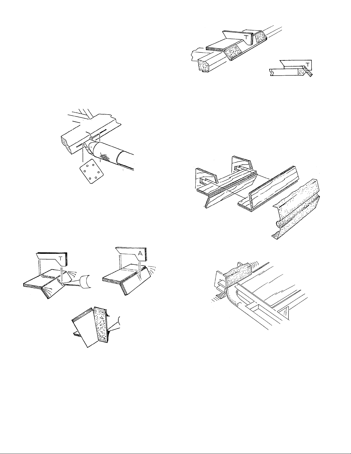
5. Use a knife to make an slot on on the center-
line for each hinge.
6. Test fit each hinge, as you proceed.
NOTE: DO NOT GLUE THE HINGES IN PLACE AT
THIS TIME.
7. From D/C sheet 6723, assemble the two
BEVELING TOOLS.
Tack glue a piece of medium sandpaper onto
each tool.
8. Using the tool marked “T,” bevel the rudder
L.E. and the elevator L.E. to a point at the
scribed centerline. Use a knife to bevel near
the air balances, as the tool cannot get into the
corner.
9. Temporarily hinge the rudder/fin assembly and
the elevator/stab assembly, in order to check
the alignment and round the perimeter of the
assembles. You may wish to use masking tape
to help hold the pieces together.
10. Assemble the ROUNDING TOOL and insert,
but do not glue, a piece of medium sandpaper
11. Use the tool to round the perimeter of the
fin/rudder assembly and the elevator/stab
assembly.
When satisfied with the shape, change the
sandpaper to fine git and repeat Step 10 to
smooth the rough surface.
12. Finish sand the entire surface of both assem-
blies, using a sanding block with fine grit sandpaper. Then separate the fudder from the fin
and the stab from the elevator.
THIS COMPLETES THE TAIL OF THE AIRCRAFT.
SET THE PARTS ASIDE UNTIL LATER.
10
SLOT
HINGE
LIKE THIS
FOR AILERON BEVEL
Page 11
WING CONSTRUCTION
1. Gather the parts needed to construct the wing:
(2) D/C SHT. 6725 5/64” BALSA PT. # 3656
CONTAINS WING RIB #3
(2) D/C SHT. 6714 5/64” BALSA PT. #3688
CONTAINS WING RIB #4 & #5
(2) D/C SHT. 6715 5/64” BALSA PT. #3689
CONTAINS: WING RIB #6 & 7,
AND AILERON RIB
(2) D/C SHT. 6716 5/64” BALSA PT. #3690
CONTAINS: WING RIB #8, #9,
#10, AND AILERON RIB
(1) L/C SHT. 6732 PLY PT. #3652
CONTAINS: WING JOINER FRONT
WING JOINER REAR,
WING DOWEL SCAB PLATE
(1) L/C SHT. 6730 BALSA PT. #3654
WING CENTER RIB
(2) L/C SHT. 6731 PLY PT. #3653
CONTAINS: RIB #2, RIB #2 TAB,
WING CENTER DOUBLER
(1) D/C SHT. 6726 PLY PT. #3658
CONTAINS :
(1) RIB SPACING GAUGE
(2) WING BOLT PADS
(2) D.C SHT. 6718 BALSA PT. #3692
CONTAINS:(8)SHEAR WEB
(4) D/C SHT. 6719 5/64” BALSA PT. #3693
CONTAINS:
(2) WING TIP SHEETING
(1) AILERON SERVO COVER SHEETING
(4) WING CENTER SHEETING
(4) D/C SHT. 6720 5/64” BALSA PT. #3694
CONTAINS:
(2) WING CENTER SHEETING
(2) D/C SHT. 6722 5/64” BALSA PT. #3695
CONTAINS:
(2) WING TIP SHEETING
(2) AILERON SERVO COVER SHEETING
(1) D/C SHT. 6723 PLY PT. #3697
CONTAINS:
(2) AILERON SERVO MOUNT
(8) DIHEDRAL FIXTURES
(5) MAIN SPARS PT. #3700
(3/8 x 3/8 x 35-1/8" BASS)
(8) AFT SPARS PT. #3701
(1/8 x 1/4 x 35-3/4" BALSA
(4) HINGE STICK PT. #3702
(1/4 x 1 x 25-1/2" BALSA)
(2) WING TIP BLOCK PT. #3703
(1-1/4 SQ x 10" BALSA)
(1) T.E. BACK-UP PT. #3704
(1-3/4 TAPERED x 7" BALSA)
(2) SHAPED L.E. PT. #3705
(12) WING SHEETING PT. #3706
(4) CAPSTRIPS PT. #3707
(5/64 X 1/4 X 22" BALSA)
(1) LANDING GEAR PLATE PT. #3708
(1/4 x 2-1/4 x 6-1/4" PLY)
(1) NYLON TAPE PT. #3709
(4) #6-32 x 1" SOCKET HD. SCREW PT. #1023
(4) #6 WASHER PT. #1140
(10) LARGE FLEX-POINT HINGE PT. #1449
(1) WING DOWEL PT. #1750
(5/16 x 4-1/2" ASH)
(1) BEVEL TOOL “A” PREVIOUSLY CON-
STRUCTED.
11
Page 12
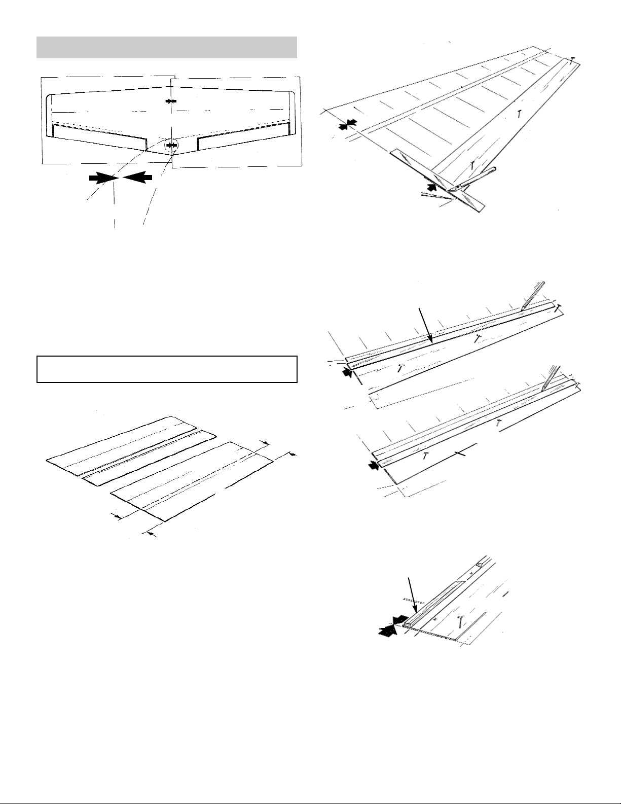
2. Cut the plan along the dotted line.
Position the left wing plan over the right wing
plan, aligning the arrows and main spar lines,
as shown.
Pin or tape the plan to the building board and
place a sheet of waxed paper over the entire
wing plan.
START THE WING CONSTRUCTION BY FIRST
BUILDING THE RIGHT WING HALF.
3. Edge-glue two assembllies of three 5/64 x 3 x
36” balsa.
Measure 3-1/4” from each end of both assem-
blies and cut, as shown, to makeT.E. SHEETS.
NOTE: The remainder of the sheeting will be used later
for the leading edge.
4. Pin a T.E. sheet over the plan.
Align a straight-edge with the wing centerline
and trim the sheet even with the centerline.
5. Align a straight-edge with the aft spar marks on
the plan and draw lines on the sheeting to
locate the spars.
WING
12
MATCH ARROWS
LEFT
RIGHT
PLAN
T.E. SHEET
T.E. SHEET
T.E. SHEET
T.E. SHEET
3-1/4"
3-1/4"
STRAIGHT-EDGE
STRAIGHT-EDGE
AFT SPAR
MARKS
MARKS
MARKS
MARKS
SPAR MARKS
FORWARD AFT SPAR
TRIM
6. Position the 1/8 x 1/4 x 36” FORWARD AFT
SPAR on the T.E. sheet, in front of the front
line.
NOTE: Make sure the spar end is flush with the cen-
terline edge of the T.E. sheet.
Glue the spar in place.
CENTERLINE
T.E. SHEETING
Page 13

7. Tape both sides of the tab break-off line on all
of the tabbed ribs.
9. Locate Rib #2 over the plan and glue it to the
T.E. sheet.
10. Angle-cut the T.E. BACK-UP to fit tight against
Rib 2.
With the back-up flush with the top of the rib,
glue the back-up to the trailing edge sheet.
Cut off the back-up flush with the wing center-
line.
11. Use the Plan to locate the distance between Rib
#3 and and Rib #2.
NOTE: Because the plan paper can stretch somewhat, due to variations in humidity, the plan is not
always an accurate representation of the desired
results. Therefore, to guarantee the ribs are spaced
correctly, a rib spacing gauge is provided. Use this
gauge to measure the distance from the previously
installed rib to the next, making sure that all ribs are
parallel.
12. Use the long side of the rib spacing gauge to
position Rib #4 from Rib #3.
13
TAPE BOTH SIDES
PLAN
T.E. BACK-UP
RIB SPACING GAUGE
RIB SPACING GAUGE
T.E. BACK-UP
CENTERLINE
Page 14

13. Using the wing-tip side of Rib #4 as a guide, cut
through the trailing edge sheeting.
14. Cut a 1/8 x 1/4” balsa aft spar to a 10-3/4” length
and butt one end against Rib #4.
Glue to the T.E. sheeting along the edge of the
rear line, as shown.
15. Using 5/64” scrap balsa as a spacer, glue an
AILERON RIB to the aft spar and the T.E. sheet.
16. From D/C sheet 6723, take an AILERON HORN
BACK-UP, marked “D” an glue it to the T.E.
sheeting, in line with the aft spar.
17. Using the long side of the rib spacing gauge,
locate ribs #5 through #9, gluing each of them to
the T.E. sheet.
NOTE: Make sure that the ribs are parallel to the
ribs on the plan, before gluing.
18. With the long side of the rib gauge, locate the
cut-off mark on the back of the aft spar, and cut.
Install Rib #10.
14
RIB #3
RIB #3
RIB #4
RIB #4
STARTING HERE
WING TIP
WING TIP
RIB SPACING GAUGE
AFT SPAR
5/64" SCRAP
CUT
AFT SPAR
10-3/4"
Page 15

Again using the 5/64” scrap spacer, locate and
glue the aileron rib to the trailing edge sheeting.
19. Using Rib #10 as a guide, cut through the T.E.
sheeting along the wing center side of the rib.
20. With the end flush with the centerline of the
wing, insert the TOP MAIN SPAR into the rib
notches and glue at each rib.
Again with the spar flush with the centerline,
insert the FORWARD AFT SPAR and glue in
place.
21. Trim the rear aft spar to fit and glue to the ribs.
22. Position the SHAPED LEADING EDGE on the
wing centerline and then glue the L.E. to each
rib.
23. Using fine grit sandpaper, flat sand the tops of
the ribs flush with the aft spars.
15
WING CENTERLINE
1/8 x 1/4 x36" BALSA
REAR AFT SPAR
TRIM
STARTING HERE
FORWARD AFT SPAR
MAIN SPAR
AILERON RIB
5/64" SCRAP
Page 16

24. Glue the top T.E. SHEETING to the spars, ribs,
and the bottom T.E. sheet.
25. From the remainder of the edge-glued sheeting
used for the T.E., measure a width of 5-3/8” from
one end and 3-7/8” at the other end.
With a straight-edge, draw a line from one mark
to the other. Then cut the sheeting along the
line, creating two tapered pieces.
26. Glue and pin the L.E. sheet to the shoulder on
the leading edge, the rib camber, and the spar.
27. Making sure the servo wire knock-out hole is on
the piece closest o the L.E., glue the three large
pieces of CENTER SHEETING to the ribs, the
L.E. and the T.E..
Pre-fit a wedge-shaped piece of sheeting to fill
the center area.
When satisfied with the fit, apply glue and slide
the piece into place, as shown.
28. Use a flexible straight-edge to trim the sheeting
flush with the wing centerline.
Punch out the knock-out hole in the sheeting to
provide access for the servo wire.
16
T.E. SHEETING
L.E. SHEETING
L.E. SHEETING
5-3/8"
3-7/8"
FLUSH WITH T.E.
SLIDE
ON CENTERLINE
BREAK OUT
Page 17

29. Trim and then glue the WING TIP SHEETING
and the 5/64” balsa capstrips in place.
THIS COMPLETES THE RIGHT WING HALF. SET IT
ASIDE AND PLACE THE LEFT WING HALF OF THE
PLAN IN THE CENTER OF THE BUILDING BOARD.
Begin building the left wing at Step 3.
DO NOT BUILD THE SECOND WING PANEL OVER
THE SAME PORTION OF THE PLAN!
WHEN THE SECOND WING PANEL IS COMPLETE,
REMOVE IT FROM THE BOARD AND CONTINUE TO
THE NEXT STEP.
30. Assemble the DIHEDRAL FIXTURES, as
shown. Note that one is offset. This fixture will
not be needed in construction of this second edition Sukhoi.
31. Working over the full waxed-paper-covered wing
plan, pin or glue the fixtures in place, as shown
above.
32. Place the wing panels onto the fixtures with the
bottom (open framework) facing up.
Check the centerline fit and, if necessary, sand
to improve fit.
When satisfied with the fit, you may wish to
anchor in place with pins and rubber bands, as
shown.
33. Carefully remove the reinforcing tape and crack
off all of the wing support tabs.
34. Test fit and then glue the MAIN SPARS to each
wing rib.
17
OFFSET
"S"
"S"
CRACK
"T"
"T"
"R"
WING IS BOTTOM-SIDE UP
Page 18

35. Test fit the front and rear WING JOINERS
between the two #2 ribs, as shown. Note the
rear joiner tabs which fit into the rib slots.
Sand any parts, as necessary, to improve the fit
of the two wing halves.
36. When satisfied with the fit, apply JET Epoxy 20
along the centerline of both wing panels and
spars and glue them together.
Epoxy the wing joiners securely in place.
After making sure all elements are correctly
aligned, allow epoxy to thoroughly cure before
proceeding. You may wish to use clamps to hold
the assembly tightly together.
37. Beginning at the wing tips, use Super Jet to glue
the corresponding SHEAR WEBS to the front side
of the top and bottom main spars in each rib bay.
NOTE: The web that goes between Rib #2 and Rib #3
must be trimmed to fit.
Center the Rib #2/3 web between the two ribs
and glue in place.
38. Test fit the L.E. sheeting. When satisfied with
the fit, apply glue to the top of the L.E., the front
rib tops, and the top of the main spar.
Install the sheeting and pin in place, as shown.
Allow to dry thoroughly.
39. When dry, determine the two Rib #2 locations
and make a mark on the leading edge.
Make a second mark at the location of the wing
joiner/spar assembly.
Referring to the above diagram, and taking
care not to cut into the ribs or the wing joiner, use a razor saw and/or a hobby knife to cut
the L.E. and the L.E. sheeting back to the wing
joiner/spar assembly between the two #2 Ribs.
40. Take one of the WING CENTER RIBS and lam-
inate a WING CENTER DOUBLER to the outboard side.
18
SHEAR WEBS
WING CENTER DOUBLER
WING CENTER RIB
WING JOINER
RIB #2
RIB #2
FRONT WING JOINER
Page 19

Take the second center rib and repeat the above
lamination, taking care to make a right center
rib and a left center rib.
41. Laminate the two center ribs together, creating a
single four-ply center rib with the doublers facing
the wing tips.
42. Insert the center rib assembly, as shown, and
then test fit the dowel, making sure it slides
through the hole in the wing joiner and into the
center of the rib assembly.
When satisfied with the fit, glue the rib assembly
and then the dowel in place.
43. Test fit and then install the CENTER SECTION
SHEETING.
44. Glue the AILERON SERVO MOUNT into the
upper slot of Rib #7 and onto the top of the spar.
Repeat for the other wing panel.
45. Temporarily mount the servo, and mark the
AILERON SERVO COVER SHEETING accordingly.
Make a cut-out for the servo.
46. Install the capstrips and the wing tip sheeting.
47. Remove the wing from the fixtures and flat sand
the end ribs, as shown.
48. Cut the 1-1/4” square WING TIP BLOCK in two
equal pieces and glue each piece to the end
ribs.
Rough carve the tips to the shape of the rib.
19
WING TIP
WING TIP
RIB #7
AILERON SERVO MOUNT
AILERON SERVO CUT-OUT
CAPSTRIPS
WING TIP
SHEETING
CARVE TO SHAPE
SAND
CENTER SHEETING
Page 20

Using first medium grit, and then fine, sandpa-
per, sand the both wing tips to a rounded and
tapered final shape.
49. Finish sand the entire wing surface, top and bot-
tom.
50. WORKING IN A WELL-VENTILATED AREA
and with plastic wrap or a plastic bag covering your finger, completely wrap the center
joint of the wing (top and bottom) with 2-1/2 “
nylon tape, smoothing a liberal amount of glue
into the fabric, as you go.
Cut a hole for the dowel and, when the wing is
fully wrapped, trim off any excess tape.
AILERON
1. Referring to the plan, determine the aileron cut
lines and transfer onto the bottom sheeting of
the wing trailing edge.
Then, carefully cut through the sheeting, as
shown.
2. Using a straight-edge, remove a strip of sheet-
ing between the two aft spars, as shown.
3. Using a razor saw, cut through the ribs and the
T.E., between the two aft spars, to separate
the ailerons from the wing.
Mark “top right” and “top left” on the root end
of each aileron, so that you will know which
piece fits into the left wing half and right right
wing half.
4. Trim the sheeting back flush with the aft spars
on both the aileron and the wing.
Flat sand along the entire length of the spar.
20
WORK IN A WELLVENTILATED AREA!
STRAIGHT-EDGE
REMOVE STRIPS OF SHEETING
ROOT END
R
L
MARK RIGHT AND LEFT
SAND FLUSH
MARK AND CUT
TRIM
Page 21

5. Trim to fit and then glue a 1/4” balsa HINGE
SHEETING onto both the ailerons and the
wing.
Sand flush to the wing and to the aileron airfoil
profile.
6. Using the CGP centerline marker, scribe a cen-
terline onto both the aileron and the wing.
Transfer the hinge locations from the plan onto
the wing and the aileron.
7. Following the same procedure used when con-
structing the control surfaces on the tail. Slot
each of the hinge locations.
8. Using the previously constructed Bevel Tool
“A”, bevel both sides of the ailerons.
Test fit the ailerons to the wing, but do not per-
manently install until after they have been
covered.
NOTE: MAKE SURE YOU CAN IDENTIFY THE
LEFT AND THE RIGHT AILERON. YOU WILL NEED
TO SCREW THE CONTROL HORN INTO THE PLY
BACKUP LOCATED INSIDE.
9. Carefully check the wing for any nicks and
deep scratches and fill with CGP Model
Mate™. Finish sand any areas that will detract
from the appearance of your model after it is
covered.
THIS COMPLETES CONSTRUCTION OF THE
WING. SET IT ASIDE UNTIL IT IS NEEDED.
21
SLOT
AILERON BEVEL
GAUGE
CHECK AILERON MOVEMENT
HINGE SHEETING
LIKE THIS
Page 22

FUSELAGE CONSTRUCTION
1. Gather the parts needed to construct the fuselage.
(2) D/C SHT.6728 LITE PLY PT. #3655
FUSE. SIDE/COWL SIDE SUPPORT
(1) D/C SHT. 6729 LITE PLY PT. #3651
FORMER "A", "C" & "D"
(1) D/C SHT. 6704 LITE PLY PT .#3663
FORMER "F","G","H" & "J"
(1) D/C SHT.6724 LITE PLY PT. #3659
CONTAINS:
(1) FUEL TANK TRAY
(1) MOTOR MOUNT BOTTOM
(1) LEFT MOTOR MOUNT SIDE
(1) RIGHT MOTOR MOUNT SIDE
(1) D/C SHT. 6706 BIRCH PLY PT. #3665
CONTAINS:
(1) FIREWALL FRONT
(1) FIREWALL AFT
(1) D/C SHT. 6707 LITE PLY PT. #3666
CONTAINS:
(1) TOP AFT
(1) WIND STOP
(2) TURTLE-DECK BACK-UP
(1) D/C SHT. 6708 PT. #3667
CONTAINS:
(1) BOTTOM AFT
(1) COWL SUPPORT-TOP
(1) D/C SHT.6709 LITE PLY PT. #3668
CONTAINS:
(1) TOP-FRONT
(1) FORMER "E"
(1) D/C SHT. 6710 BIRCH PLY PT. #3669
(1) TURTLEDECK
(2) L/C SHT. 6731 LITE PLY PT. #3653
CONTAINS:
(1) WING SADDLE DOUBLER
(1) L/C SHT. 6732 LITE PLY PT. # 3652
CONTAINS: (1) FORMER B
(1) FORMER B2
(1) LANDING GEAR PLATE
(1) WING MOUNTING BLOCK PT. #3672
7/16" TAPER x 5-1/8" BASS
(1) FRONT TOP SHEET PT. #3673
1/32 x 8 x 9-1/2" BIRCH PLY
(3) GUSSET PT. #4217
1/2" TRI x 8" BALSA
(1) .078 x 13-5/8” THREADED ROD PT. #1281
(2) ENGINE MOUNT PT. #1466
(6) 6-32 BLIND NUTS PT .#1124
(2) 6-32 x 1" SOCKET HEAD SCREW PT. #1023
(2) #6 FLAT WASHER PT. #1140
(2) #6 x 3/4" O.D. FLAT WASHER PT. #1144
(1) FUSELAGE PLAN PT. #2123
2. Making sure the marking lines are facing out
and that the perimeter is lined up, laminate the
two 1/8” birch plywood FIREWALL parts with
SUPER JET.
22
MARKING LINES FACING UP
Page 23

3. When the firewall has thoroughly dried, tack-
glue the motor you intend to use to the
ENGINE MOUNTS.
Align the marks on the engine mounts with the
vertical marking line on the firewall.
Center the engine mounts on the horizontal
marking line, as shown, and mark all four hole
locations.
Mark the location of the throttle pushrod exit in
line with the throttle control.
4. Drill a 5/32” diameter hole at each hole loca-
tion.
Flip the firewall over and insert four 6-32
BLIND NUTS. Seat them with a soft hammer
blow.
Making sure that the glue does not get into the
threads, coat the edges of each blind nut with
CA glue. Then, set the firewall aside.
NOTE: Flying the Sukhoi with one of the larger
recommended engines will produce spectacular
results. However, these larger 4-stroke engines
generate a lot of vibration. Therefore, you may
wish to install two elevator servos. If you choose
this option, refer to the following instructions.
(a) Do not punch out the elevator exit. Instead, glue it
permanently in place.
(b) Cut a hole for the servo on each side of the fuse-
lage, as shown.
(c) Make two doublers from scrap 1/8 x 1/4 x 1-1/4"
ply and glue the forward doubler to the INSIDE of
the fuselage. Glue the rear doubler to the OUTSIDE of the fuselage. This helps to position the
servo more parallel to the elevator pushrod.
(d) From the fuse side punch-out, cut off about a 1”
piece from the end and glue this strip back into the
fuse.
(e) When mounting the servos, it is essential that one
of the servos be reversed. The easiest way to
accomplish this is to use a special Y- harness
that will reverse one servo from the other.
Alternatively, "mix" your elevator channel into an
exta channel in your radio, and then reverse to
achieve proper direction. Consult your radio manual for details.
(f) Using the elevator pushrod wire supplied in the kit,
trim to fit, making sure there are no bends. When
adjusting throws, try to get both elevators to move
equally.
TWO SERVO OPTION
Tape together and place under a weight until
dry.
23
1/2 ENGINE WIDTH
ALIGN MARKS
PLY DOUBLER
SERVO CUT-OUT
DO NOT REMOVE
FROM PUNCH-OUT
1”
FORMER J
Page 24

7. Positon, but DO NOT GLUE, FORMERS A, B,
B2, C, F, G, and H. Use a rubber band at each
former location to hold the fuselage together.
8. Slide the TOP FRONT (note slant) and the
TOP AFT under the rubber bands and into the
alignment notches. DO NOT GLUE.
9. Invert the fuse and slide the BOTTOM AFT and
the LANDING GEAR COVER PLATE into the
notches provided. Again, DO NOT GLUE.
10. Position the fuselage assembly over the bottom
view of the plan and check the alignment.
Secure the assembly with small pieces of mask-
ing tape, as shown.
Sight check along the fuselage to ensure that
the fuse is straight, not twisted.
5. Lay the FUSELAGE SIDES on a flat surface
side-by-side, in a mirror-image configuration.
This will ensure that you build a left and a right
fuselage side.
Aligning the front and rear points for correct
positioning, glue a WING SADDLE DOUBLER
to each fuse side.
6. With the doublers face-to-face, rubber band
the fuse sides together at the rudderpost location.
24
ALIGN
ALIGN
TAPE IN PLACE
PLAN
LIKE THIS
NOT LIKE THIS
SLANT
Page 25

11. When the fuselage is perfectly aligned, glue all
of the areas where the sides, top, bottom, and
formers join.
12. Insert the remaining 6-32 blind nuts into the pre-
drilled holes in the WING MOUNTING BLOCK.
NOTE: Make sure the blind nuts are inserted into the
side of the mounting block where the holes are
centered.
Tap with a hammer to ensure the spurs are fully
set into the wood.
13. With the blind nuts on the inside the fuse, place
the mounting block into the cut-outs in the wing
saddle doubler and the fuselage sides. Trim, if
necessary, to achieve a good fit. Then, using
epoxy, glue in place.
NOTE: THIS IS A HIGH STRESS AREA. THE BETTER THE MOUNTING BLOCK FITS INTO THE
SOCKET, THE STRONGER THE JOINT WILL BE.
14. Form four 2-ply assemblies from the four LAND-
ING GEAR DOUBLERS.
When the laminated assembles are dry, test fit
in position. The assemblies with the tabs fit at
the slotted locations between Former B and
Former B2. The assemblies without the tabs
go along the fuse sides.
Epoxy securely in place.
15. Epoxy the 1/4 x 2-1/4 x 5-11/16” ply landing gear
plate between the fuse sides and into landing
gear doublers.
Now get the wing, which will be needed for the next
few steps.
16. Place the fuselage, bottom up, on a flat surface.
Glue the WIND STOP to the fuse sides and the
doublers.
Insert the wing dowel through the slightly over-
sized hole in Former B2. Slide the wing as far
forward as it will go. Make sure that the wing fits
tightly all along the wing saddle.
17. True the wing to the fuselage by adjusting the
distance from the wing-tip to the tail until both
dimensions are equal. Mark the wing for reference and tape in place.
25
HOLE IS CENTERED
TABBED DOUBLERS
UNTABBED DOUBLERS
MARK WITH TAPE
WIND STOP
L.G. PLATE
GLUE ALL SEAMS
WING DOWEL
Page 26

20. Drill a 5/32” hole at the centermark on each
WING BOLT PAD.
Place each pad on a 6/32 x 1” socket head
screw and screw part way down into the blind
nut.
21. Install the MOTOR MOUNT BOTTOM and both
MOTOR MOUNT SIDES to the fuse,as shown.
Use a generous amount of glue, as this is a high
stress area.
22. Using the 1/2” balsa tri stock, trim and fit the
FIREWALL GUSSETS in place. They should be
located 1/4” back from the edge of the motor
mount, as shown.
23. With the blind nuts to the inside and the V-notch
on top, epoxy the FIREWALL into the fuse. Use
plenty of epoxy and let dry thoroughly.
18. Carefully turn the wing/fuselage assembly to an
upright position.
Cut the threaded segment from one of the .078
x 13-5/8” threaded rods and use as a drill bit.
Don’t use anything larger than 7/64”
(.109/2.7mm) in diameter.
Using the blind nuts as locators, drill a pilot hole
through the bottom of the wing.
Remove the wing from the fuselage and, using
the pilot hole as a guide,
19. Test bolt the wing to the fuse and, following the
procedure used before, again check the alignment by making sure the dimensions from wing
tip to tail are still equal on each side of the
model.
Being careful not to get glue on the dowel, glue
the WING DOWEL SCAB PLATE over the wing
dowel and to the front side of Former B2.
Glue the LANDING GEAR COVER PLATE in
position.
Make sure the holes are aligned. Then, taking
care to not get glue in the hole or on the
screw, apply CA glue to the bottom of the
wing bolt pad and glue to the wing.
NOTE: Brush On™ Super Jet is excellent for this job.
26
1/14" BACK FROM
FRONT EDGE
1"
"V" NOTCH AT TOP
NO LARGER THAN 7/64"
5/32" HOLE
WING DOWEL SCAB
PLATE
Page 27

24. Trim and glue the remaining firewall gussets in
place, as shown.
25. Glue FORMER D and FORMER E into the
notches in the fuselage top.
26. Overlapping the side 3/16”, as shown, glue one
edge of the 1/32” ply FRONT TOP SHEET to
the fuselage.
When the glue is dry, use a spray bottle to soak
the sheet with water. Then SLOWLY roll the
sheeting to the opposite side of the fuse, gluing
to the formers as you go.
Bevel-sand the plywood edge at the fuselage
overlap.
Fill the joint area with JET MODEL MATE™ and
sand smooth.
27. Glue FORMER J directly over FORMER H.
28. Mark the centerline onto the horizontal stabilizer
and onto the stab platform on the fuselage.
Position the stab on the stab platform, making
sure to locate it on the centerlines and against
former J.
Using epoxy, glue the stab to the stab platform.
27
3/16" OVERLAP
JET MODEL MATE
FILLER
ALIGN
STABILIZER
FUSLAGE
MATCH THE CENTERLINES
DIRECTLY ABOVE
WATER SPRAY
FORMER D
FORMER E
Page 28

29. Insert the vertical fin L.E. into the slot in Former
J and slide the rudder post into the fuselage.
Check to make sure the fin is at a 90º angle to
the stab and then glue in place.
Glue the two TURTLEDECK BACK-UPS, as
shown.
30. Slide the 1/32” ply TURTLEDECK back around
the fin.
Again using the spray bottle and water, soak the
top center of the turtledeck.
31. When satisfied with the fit, apply glue to the for-
mers, fuselage, fin and stab.
Immediately wrap the turtledeck down onto the
fuse and tape in place until dry.
When thoroughly dry, bevel-sand the plywood
edge where it overlaps the fuse. Also sand the
turtledeck front flush with Former F.
As with the top front sheeting, fill the step with
JET Model Mate™ and sand smooth.
32. Go over the fuselage, sanding all seams and
joints.
Then, finish sand the entire fuse assembly with
fine grit sandpaper to provide a smooth surface
for covering.
THIS COMPLETES THE BUILDING PORTION OF
YOUR MODEL. MAKE SURE ALL PARTS ARE WELLSANDED AND ALL NICKS ARE FILLED. THEN PROCEED TO THE “GENERAL INFORMATION BOOK”,
COVERING SECTION. AFTER COVERING THE
MODEL, RETURN TO THE FINISHING SECTION IN
THIS BOOK AND CONTINUE.
Before the glue has set and with the fuse sitting
flat on the work surface, check to make certain
the stab is parallel to the building board.
SLOWLY wrap the plywood around the form-
ers and down onto the fuselage sides.
Check the fit and trim, if necessary.
28
EQUAL OVERLAP
FILL STEP
LIKE THIS
NOT LIKE THIS
Page 29

FINISHING THE MODEL
CANOPY INSTALLATION
1. You will need the canopy and paint or covering.
2. Cover the cockpit interior with black or gray
iron on film or paint, as preferred.
3. Trim the canopy around the perimeter, along
the trim line.
4. Using epoxy or a clear canopy glue, glue the
canopy overlap to the fuselage sides and
around the front and back of the cockpit.
FUEL TANK INSTALLATION
1. Gather the following items:
(1) D/C SHT. 6724 PT. #3659
TANK TRAY
(1) FUEL TANK NOT INCLUDED
(1) 12” LENGTH OF FUEL LINE NOT INCLUDED
(2) #64 RUBBER BANDS NOT INCLUDED
(1) FOAM PADDING NOT INCLUDED
2. Rubber band the foam pad and the fuel tank to
the tank tray.
3. Thread the fuel line through the “V” notch in the
firewall and attach them to the tank.
Pull the line forward and glue the tank assem-
bly onto the locating shoulders on Former A
and Former B, inside the fuselage.
Connect the fuel lines when you mount the
engine.
TAILWHEEL ASSEMBLY
1. Collect the following items:
(1) TAILWHEEL ASSEMBLY PT. #5819
(1) ADJUSTABLE HORN BRACKET PT. #1424
(2) #2 x 3/8” SHT. METAL SCREW PT. #1084
(1) 1-1/4” TAILWHEEL NOT INCLUDED
(2) CGP 3/32” WHEEL COLLAR NOT INCLUDED
2. Cut a narrow slot through the fuse bottom and
secure the tailwheel brack assembly with the
#2 x 3/8” screws.
3. Notch the bottom of the rudder to mount the
horn bracket.
Slide the bracket into the wire and glue into the
notch. DO NOT GLUE BRACKET TO WIRE.
4. Trim the wire and install tailwheel, as shown.
29
#2 x 3/8" SCREW
HORN BRACKET
CUT SLOT
NOTCH
FUEL TANK TRAY
Page 30

CONTROL SURFACE/RADIO INSTALLATION ENGINE PUSHROD INSTALLATION
1. Collect the following items:
(1) 3/8" x 3/8" x 16" BASS PT.#3674
PUSHROD
(2) LONG CONTROL HORNS PT.#1407
(4) 2-56 x 3/4" PAN HEAD SCREWS PT.#1042
(3) SNAP LINKS PT.#1405
(2) HOODED PUSHROD EXITS PT.#1453
(1) .078 x 10" THREADED ROD PT.#1272
(2) .078 x 13-5/8" THREADED ROD PT.#1281
1. If you did not do so immediately after covering
the model, thin CA glue the hinges in place,
permanently attaching the elevator to the stab
and the rudder to the fin.
Permanently install the ailerons on the wings.
2. Referring to the GENERAL INFORMATION
BOOK and to the specific details and guidelines that came with your radio system, install
the radio, servos, and battery. A servo tray is
provided in this kit; however, it may be necessary to modify it to suit your equipment.
ELEVATOR PUSHROD INSTALLATION
2. Cut 3-1/2” off the end of the basswood
pushrod. Set this piece aside, as it will be
need for attaching the cowling and for elevating the rudder servo.
3. Using the TOP VIEW of the fuse plan as a tem-
plate, bend the two 13-5/8” threaded rods in
the correct configuration.
Glue the rods to the bass pushrod and wrap
with a strong thread. Coat the thread with
more glue.
4. Referring to the plan, cut the 10” threaded rod
to size. Attach to the other end of the bass
pushrod, wrapping with string and coating with
glue.
1. Gather the necessary parts.
(4) 6-32 x 3/4" SOCKET HEAD SCREW P T.#1022
(4) #6 M.S. WASHER PT.#1140
(1) .034 I.D. x 18" NYLON TUBE PT.#1657
(1) .030 x 34" CABLE PT.#1289
(2) P.R. CONNECTOR BODY PT.#1375
(2) 4-40 x 3/16" SOCKET HEAD SCREW PT.#1003
(1) NYLON SNAP-NUT (6/set) PT.#1461
(4) #6 x 3/4" SHT. METAL SCREW PT.#1082
2. Bolt the MOTOR MOUNTS to the firewall,
using four 6-32 x 3/4” SOCKET HEAD
SCREWS and #6 washers.
3. Referring to the plan for correct engine/cowl
position, screw the engine to the mounts with
four #6 x 3/4” SHEET METAL SCREWS.
4. Insert the NYLON GUIDE TUBE in the previ-
ously drilled hole in the firewall. Glue in place.
5. Install the CONNECTOR BODIES to the
engine throttle arm and the throttle servo arm.
Secure with the NYLON SNAP-NUT.
6. Thread the .030 x 34” CABLE through the
nylon tube and into the connector bodies.
With the servo at low motor position, and the
carburetor closed, lock both ends of the cable
with two 4-40 x 3/16” SOCKET HEAD
SCREWS.
7. Attach the fuel lines and install the muffler.
30
3-1/2"
PLAN
ELEVATOR SERVO
BEND WIRE PER PLAN
3/32" DRILL
CONNECTOR BODY
GUIDE TUBE
4-40 x 3/16" SOCKET
HEAD SCREW
Page 31

AILERON SERVO CONNECTION LANDING GEAR INSTALLATION
RUDDER CABLE INSTALLATION
1. Collect the following items:
(4) #2 x 5/16" SHT. METAL SCREWS PT.#1086
(2) .078 x 10" THREADED ROD PT.#1272
(2) SNAP LINKS PT.#1405
(2) LONG CONTROL HORNS PT.#1407
(2) SERVOS NOT INCLUDED
(2) 18" SERVO EXTENSIONS NOT INCLUDED
2. Install the aileron servos, if you have not
alreeady done so.
3. Lay the triangle along the hinge line and over
the last hole on the servo arm to locate the
control horn.
Attach the control horns by screwing two #2 x
3/8” screws into the plywood back-up inside
the ailerons.
4. With the ailerons and the servos in the neutral
position, connect the pushrods.
1. Collect the following items:
(1) FORMED ALUMINUM GEAR PT.# 1367
(2) THREADED AXLE PT.# 1369
(4) #6 x3/4” SHT. METAL SCREW PT. #1082
(4) #6 WASHER PT. #1140
(2) 3-1/2" WHEEL (NOT INCLUDED)
( 4) C.G.P 3/16" WHEEL COLLAR (NOT INCLUDED)
2. Mark the centerpoint of the landing gear cover
plate and the formed LANDING GEAR, making
sure they are aligned.
3. Using four #6 x 3/4” sheet metal screws, per-
manently mount the landing gear through the
cover plate into the 1/4” ply landing gear
mount.
4. Bolt the AXLES to the landing gear and install
the wheels.
NOTE
The SUKHOI uses a pull-pull system. Therefore, the
rudder servo must be located as shown on the plan to
ensure the correct cable alignment with the cable exits.
This feature was designed into the fixtured placement
of the servo tray supplied in this kit. If you decide not
to use the tray, make sure that you place the servo as
shown on the plan.
1. Collect the following items:
(1) D/C SHT. 6712 PLY PT. #3671
CONTAINS RADIO TRAY
(2) .030 x 34" CABLES PT.#1289
(4) THREADED COUPLERS PT.#1192
(2) LONG CONTROL HORNS PT.#1407
(2) 2-56 x 3/4" PAN HEAD SCREWS PT.#1042
(4) SNAP LINKS PT.#1405
(2) HOODED P.R. EXITS PT.#1453
(1) 3/8" SQ. x 2" BASS
CUT FROM PT.#3674
31
#2 x 5/16" SCREW
ALIGN WITH HOLE IN
SERVO ARM
"Z"BEND
.078 WIRE
#6 x 3/4" SCREW
Page 32

2. Solder a threaded coupler to one end of each
cable.
Lay the cable over the plan and cut to length.
Solder a threaded coupler to the cut end of
each cable.
3. Glue the hooded exits to the fuselage and
thread the cable assemblies from the rudder
servo opening to the control horns.
4. Install a CONTROL HORN on each side of the
rudder, directly opposite from one another.
Drill two 1/16” holes into one of the horn and
thread the two 2-56 screws into the horn.
5 Thread the SNAP LINKS onto the threaded
couplers and attach the links onto the rudder
control horns.
5. Cut the remaining 3/8 sq. piece of bass from
the elevtor pushrod into a 2” length. Then, cut
this piece into two equal pieces.
Glue the two small blocks to the servo tray to
raise the rudder servo, as shown on the plan.
Mount the servo (a ball-bearing servo is rec-
ommended) and, with the servo in the neutral
position, attach and adjust the cables until the
rudder is centered.
NOTE: Cables need only be tight enough to eliminate
slack.
32
RUDDER SERVO
SERVO TRAY
2-56 x 3/4"
SCREW
1/16" DRILL
SOLDER
1"
Page 33

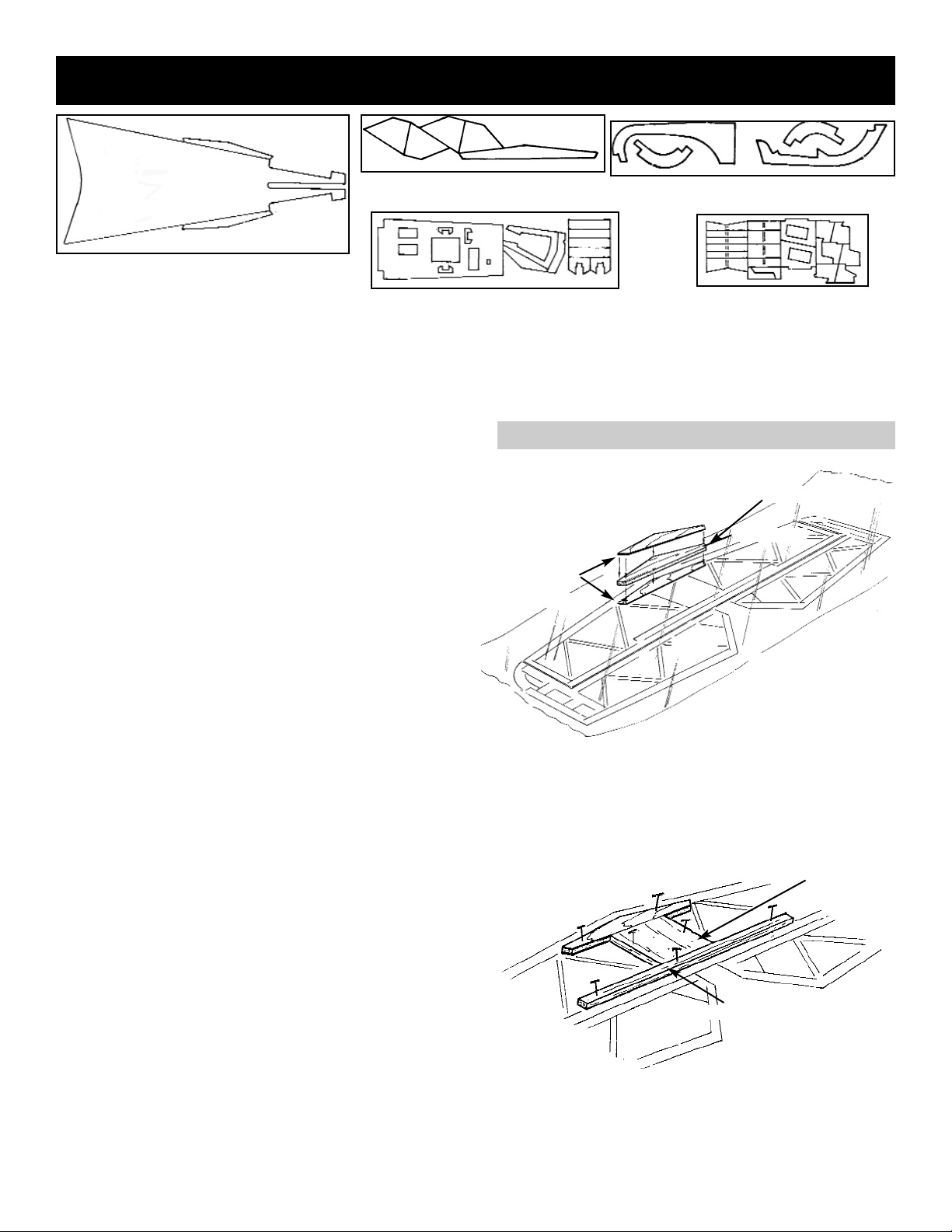
33
Assembling The Engine Cowling & Belly Pan
Page 34

343536
Page 35

Page 36

Page 37

SETTING CONTROL SURFACE TRAVEL
Use the control surface travel gauges to correctly set
up the surface deflections. The gauges provide you
with two setting: a gentle response setting and a more
aerobatic setting. Even if you are an experienced pilot,
we encourage you to start out at the gentle setting and
then move to the aerobatic mode after you become
more familiar with the characteristics of this aircraft.
AILERON GAUGE
ELEVATOR GAUGE
RUDDER GAUGE
1. Place the gauge anywhere along the wing.
Align the center of the aileron to the mark in the
neutral position.
With the control stick full left and full right,
match the center of the aileron to the mark.
2. Adjust the horn bracket up or down along the
hole selection to achieve the correct travel setting.
NOTE: This is a good time to make sure the control
surfaces are responding correctly. You would
not want to correct a left bank with more left, so
check it now!
1. Place the elevator gauge anywhere along the
elevator hinge line.
2. Adjust the servo arm hole along with the con-
trol horn hole to achieve the desired setting.
Check each elevator.
1. Position the rudder gauge at the top of the fin at
the hinge line. Follow the same procedure
used for the elevator to achieve the desired
travel.
37
HIGH THROW
LOW THROW
HIGH THROW
LOW THROW
HIGH THROW
LOW THROW
UP ELEVATOR
NOTCH POINTS UP
NOTCH POINTS
DOWN
3/16"
3/8"
1/4"
LEFT AND RIGHT RUDDER
DOWN ELEVATOR
Page 38

FLYING THE SUKHOI
The CARL GOLDBERG PRODUCTS SU-26 probably
flies more like its full-size cousin than any other kit on
the market. We have designed it deliberately to make
unlimited aerobatics practical for the average pilot. In
fact, if you are comfortable with a low-wing sport aircraft, you should have no difficulty in being successful
with the GOLDBERG SUKHOI. Take great care in
building and setting up your aircraft and the SU-26 will
reward you with many hours of exciting aerobatics.
THROWS
We have provided two sets of throws. It is highly recommended that you start with the lower throws and,
after a few flights, work your way up to the higher settings, if you desire. If you are using a computerized
radio, always use the highest percentage possible and
then mechanically adjust for the proper throw. Also,
because of the high deflection and generous area of
the control surfaces, it is recommended that you use
exponential to soften the feel around neutral. At the
lower control settings, little, if any, expo is needed. Try
15-20% at first and, for the higher settings, try about
40% for all controls. These settings are only suggestions and may be modified "to taste."
ENGINES
This SUKHOI was designed around the .90 two-stroke
and the 1.20 four-stroke engines, which will yield
excellent performance. . The secret is to not build too
heavy. Remember, a bigger engine is not better, as it
adds weight, vibration, etc. Therefore, DO NOT use a
larger-than-recommended engine, which could result
in structural failure of the aircraft. As for props, we
have found that a 15-8 to 16-8 propeller and a properly sized spinner seem to work well on these engines.
FIRST FLIGHT
Double and triple check that all is in order...extra time
here is always well spent! When satisfied with controls, engine response, etc., you're ready.
When taxiing, we recommend you always maintain full
up elevator, especially when flying off grass. Point the
nose into the wind and gradually apply full power. As
the SUKHOI accelerates, reduce the elevator setting
so that, when the aircraft is ready to fly, you will have
just enough up elevator to rotate and climb out at a
shallow angle. Also, during the application of power,
due to engine torque, the SUKHOI will veer to the left,
so be prepared to hold some right rudder. In all probability, no more than 10-20% rudder input will be needed, and this should be maintained during the initial
climb-out. This take-off technique is not only best for
the SUKHOI, but is the proper way to take off any aircraft, particularly a tail-dragger.
Once in the air, the SUKHOI should have a fairly balanced feel. Rolls will be relatively quick, but very pre-
dictable, and pitch is very positive, but not too sensitive.
Inverted flight takes a small amount of down elevator to
sustain. The rudder is large and powerful, which makes
"stall turns" a breeze and "knife edge flight" a pleasure.
On our prototypes, we did not require any mixing to
compensate roll. The nose did pitch up ever so slightly, but we did not feel it necessary to "dial" it out with the
radio. Snap rolls are very quick and stop instantly. A
note on snaps: you don't need high rate rudder and
elevator to get the SUKHOI to snap properly. If you do
that, the aircraft simply goes deeper in the stall and
decelerates rapidly. Normally, this is not a problem, but
if you try to snap roll on a vertical up-line, it can almost
stop the aircraft. If you snap with low rate, the SUKHOI
will continue to climb cleanly.
Lomcevaks are an absolute delight with the SUKHOI. It
seems to do all variations well, including one in particular. From level flight and full power, pull up about 60º,
roll right 90º, then snap inside left and, after about one
full rotation, apply full down and opposite aileron...then
hang on! Almost always, you can execute two full tumbles...and sometimes more.
Landing the SUKHOI offers no real difficulties.
Because of the low wing loading, it can land very slowly, but be aware of the long landing gear and try to get
most of the "fly" out before you touch down. If you happen to touch down with too much airspeed, be prepared
to release some of the up elevator to prevent the aircraft from bouncing back into the air.
REMINDER
As good as this SUKHOI is, all aircraft have limitations and this one is no exception. Using care and
common sense will help ensure the survivability of
your aircraft. And, of course, always think and fly
safely.
38
Page 39

COLOR SCHEME
DECAL PLACEMENT AT BUILDER'S DISCRETION
PAINTED CANOPY FRAME
BLACK
WHITE
BRIGHT RED
BLACK
WHITE
BRIGHT RED
The following colors were used on the "show
model" photographed for the kit box. Lighting and
printing may alter the appearance of these colors
on the box.
Bright Red
White
Black
39
 Loading...