

Page 1
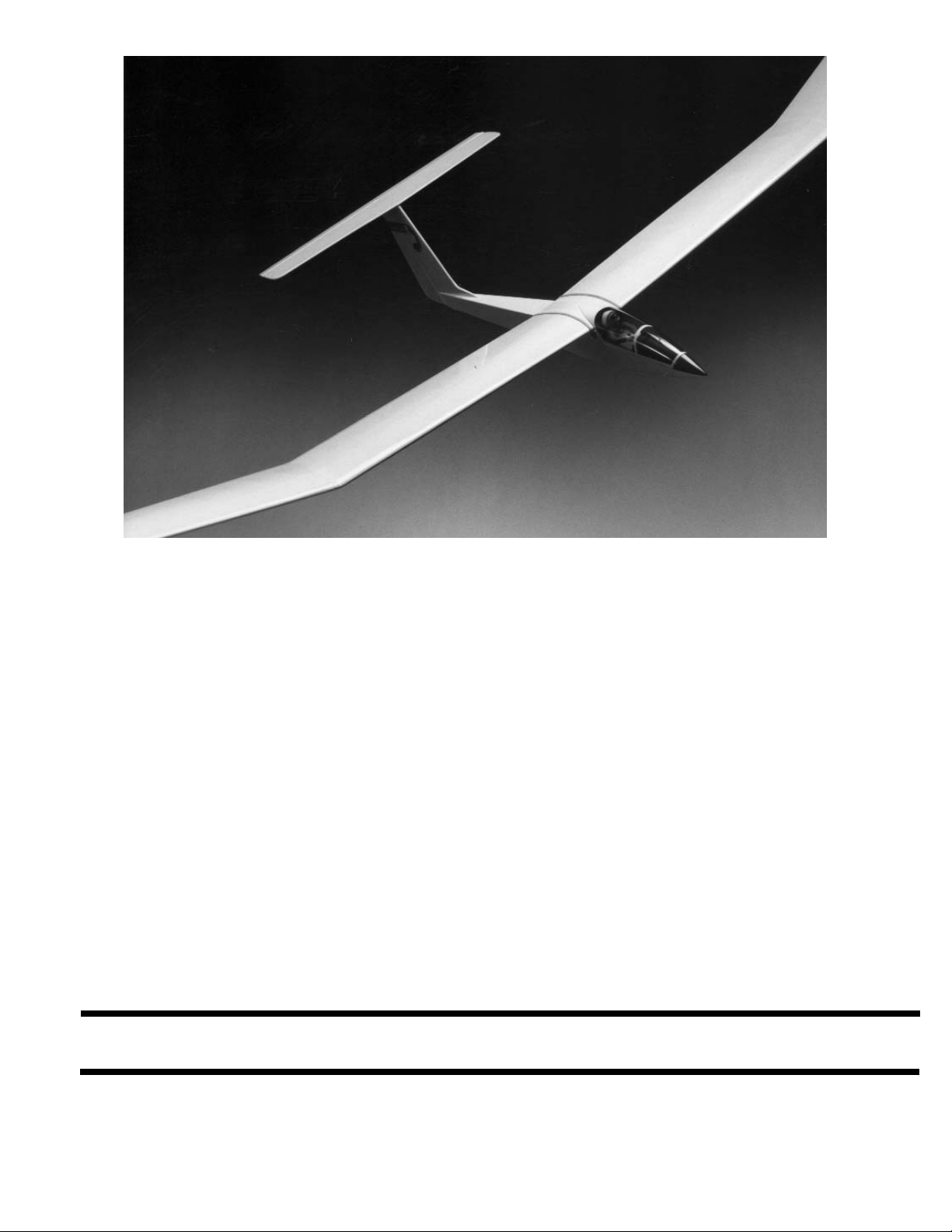
The SOPHISTICATED LADY is a sailplane design that blends simple straight-forward construction with
the elegant styling of a sleek, full-scale soaring machine. The clean lines have not compromised the
functionality of this model aircraft, which you will find a delight to fly both in thermals and on the slope
And if it's competition you desire, this "Lady" can compete with the best and look great in the winners'
circle!
Although a simple two-channel radio meets the minimum requirements for piloting this model, a third
channel is more desirable, enabling you to control airborne "power-on/power-off" commands when the
electric power pod is installed. The Carl Goldberg Products Electric Power Pod (Item #678) is an optional accessory which provides power assistance for small-field launching, or when the towline is just too
much trouble. A small gas engine is also a power option. In addition, your sailplane so may be
launched via high start, hand tow, or winch, and, if you live in a hilly or mountainous area, you may wish
to simply pitch your glider off the slope. Whichever method you choose, the SOPHISTICATED LADY
will provide many hours of enjoyment.
WARNING!
THIS IS NOT A TOY! A radio-controlled model is not a toy and is not intended for persons under 16 years old. Keep this
kit out of the reach of younger children, as it contains parts that could be dangerous. A radio-controlled model is capable
of causing serious bodily injury and property damage. It is the buyer’s responsibility to build this kit correctly and to properly install the motor, radio, and all other equipment. Test and fly the finished model only in the presence and with the assistance of another experienced R/C flyer. The model must always be operated and flown using great care and common
sense, as well as in accordance with the safety standards of the Academy of Model Aeronautics (5151 Memorial Drive,
Muncie, IN 47302, 1-800-435-9262). We suggest you join the AMA and become properly insured prior to flying this model.
Also, consult with the AMA or your local hobby dealer to find an experienced instructor in your area. Per the Federal
Communications Commission, you are required to use only those radio frequencies specified “for Model Aircraft.”
Pt. # 2083 1/02
INSTRUCTIONS
Carl Goldberg Products, Ltd.
P.O. Box 818 4462 Oakwood Road Oakwood, GA 30566 Phone # 678-450-0085
Fax # 770-532-2163 E-mail: Questions@carlgoldbergproducts.com
©Copyright 1986
Sophisticated Lady
Page 2

ITEMS NEEDED TO COMPLETE KIT
1 RADIO GUIDANCE SYSTEM (2-CHANNEL
MINIMUM)
2 2-OZ. BOTTLE CA GLUE
2 ROLLS OF IRON ON COVERING
1 TUB JET MODEL MATE™ FILLER
1 BOX OF EPOXY
1 BOX #64 RUBBER BANDS
UltraCote is a registered trademark of Horizon Hobby Distributors
ADDITIONAL ITEMS FOR REMOVABLE WINGTIP
1/8” x 3” x 18” HARD BALSA SHEET
PIECE 3/32” x 12” MUSIC WIRE
3/32 I.D. x 6” BRASS TUBE
3/4” VINYL ELECTRICAL TAPE
OPTIONAL ITEMS
1/2” x 8” x 12” CGM FOAM RUBBER
FUEL PROOF PAINT
SERVO MOUNTING TAPE
CGP SCUFF GUARD
TRANSPARENT SPRAY ENAMEL FOR
CANOPY
NECESSARY TOOLS AND SUPPLIES
MISCELLANEOUS RUBBER BANDS
WAXED PAPER
MODELING KNIFE AND RAZOR BLADES
SANDPAPER (ASSORTED GRITS, INCLUDING
MEDIUM (150) AND FINE (220-320)
SANDING BLOCK
"T" PINS (at least 75)
BUILDING BOARD (24" x 60")
ELECTRIC DRILL
1/16" ABD 1/8" DRILL BIT
ALLEN WRENCH (.050 FOR #4 SOCKET SET
SCREW)
SMALL SCREWDRIVER (1/8” BLADE TIP)
MASKING TAPE
SMALL PLIERS
COVERING IRON (OR SMALL HOUSEHOLD
IRON)
HEAT GUN (OPTIONAL)
10" 30-60-90 DRAFTING TRIANGLE
YARDSTICK
FLEXIBLE STRAIGHT-EDGE
PENCIL
LIMITED WARRANTY
Carl Goldberg Products, Ltd. takes pride in the care and attention given to the manufacture of its model airplane kits.
The company warrants replacement of any materials found to be defective for their intended use, prior to their use in
construction of the aircraft, provided the buyer requests such replacement within a period of one year from the date of
purchase and provided the defective part is returned, if so requested by the company.
No other warranty, expressed or implied, is made by the company with respect to this kit. The buyer acknowledges and
understands that it is his responsibility to carefully construct a finished flying model airplane and to fly it safely. The
buyer hereby assumes full responsibility for the risk and all liability for personal or property damage or injury arising out
of the buyer's use of the components of this kit.
2
SELECTING RADIO CONTROL EQUIPMENT
Radio sets are battery powered with either dry cells
or the more reliable, rechargeable nickel-cadmium
(ni-cad) batteries. Although ni-cad powered units
are more expensive, the cost of routinely replacing
worn out batteries may be much higher in the long
run. Many of the radio systems now available feature "servo reversing" switches which allow you to
reverse the response of the servo. This simplifies
radio installation and is worth considering.
Exponential or dual rates are popular features
which, if used properly, can help smooth out the
flight of a sensitive model. Your local hobby dealer
should be able to help you select the proper radio
for your needs and skill level. Consider reliability
and service, as well as price. And be sure to get a
system designated for aircraft, as only certain frequencies are available for model aircraft.
Page 3

USING THIS INSTRUCTION MANUAL
Before you start gluing and sanding, take some time
becoming familiar with the plans and looking through this
entire Instruction Booklet. It is designed to guide you through
the construction process step by step, so build in the order
given in this book. Building options, as well as balancing, setup, and flying the model are covered.
Like a full-size airplane, the SOPHISTICATED LADY is
built from basic structures (stabilizer, fin, wing, etc.), which
are then assembled into the complete airplane.
Special procedures or comments will usually be
explained before a step, so you will be prepared. If a step
begins with a statement like "Note," "Warning," or "Important,"
it is a good idea to read through the step before doing it.
A check-off box appears at the beginning of each step.
Check these boxes as you build, so you can tell at a glance
what steps you have completed. Some steps are repeated
and must be marked twice, as in the case of the left and right
wing panel.
Some of the instructions deal with general procedures.
Boxes are not needed for these sections.
HOW TO READ THE PLAN
There is one plan sheet in this kit, showing the Fuselage
(Body), the Wing, and the Tail Parts. Everything on the plan
is drawn to full-size and shape and shows how the finished
parts fit together.
The plan is drawn to show the model completely assembled, but as a result, the areas inside or underneath are covered up, making it hard to understand how these parts fit
together. Therefore, for clarity, some parts are drawn with
hidden lines, others with breakaway views, and some are
entirely removed from the structure and shown separately.
For example, on the fuselage, the left side of the completed model has been removed to show the details inside.
Sometimes a surface is broken away to reveal the detail
behind or underneath. Dashed lines indicate details that are
hidden behind or under another part of the surface.
The model is made from four varieties of wood: balsa,
bass, birch, and various plywoods. Each kind of wood has its
own characteristic end grain pattern (as viewed from the end)
which has been drawn on the plan. You can easily use these
end grain patterns to identify what kind of wood is shown for
a part, if you are in doubt.
INTRODUCTION
HOW TO USE THE PLAN
The plan is used in several ways. The wings, stabilizer, and
fin are assembled directly over the plan. Each wood part is
matched over its corresponding location printed on the plan
and pinned in place. To prevent ruining your plan from gluing
your wings, etc. to it, cover the area you are working on with
waxed paper.
The paper the plan is printed on can expand or contract slightly with changes in temperature or humidity.
Because of this, a preformed part such as the notched
wing trailing edge may not exactly match the plan. This
is no problem, as slight deviations in the outline or size will not
noticeably affect flight performance.
Because the fuselage plugs together and is self-aligning,
it is not built directly over the plan. As you assemble the fuselage, you will find the plan helpful in identifying parts and how
things fit together.
IDENTIFYING PARTS
Parts for the wing are bundled together; likewise, parts
for the tail assembly are also grouped. Die-cut plywood and
balsa sheets of common sizes are bundled together, so they
are less likely to be damaged during shipping and handling.
The various screws, hinges, and fittings are packaged in
plastic bags.
The plan also shows the installation of a typical radio,
battery and all remaining equipment and hardware needed to
complete the model. By referring to the examples shown, you
should be able to install your own radio, etc., even if it is not
the same as what is shown on the plan.
PREPARING FOR ASSEMBLY
Set a flat, warp-free pinning board on your work bench.
Any material that accepts pins, such as insulation board, soft
plywood, or dry-wall (sheet rock) will work. Important: any
warps or bends in the pinning board will result in wings or tail
surfaces that are also warped or bent, making your model
more difficult to fly. Make sure that the pinning board is flat by
laying a straight edge across it. You may be able to correct a
warped board by shimming its low areas.
Position the area of the plan (such as the stabilizer) on
which you are going to build over the pinning board and tape
it in place so the plan lays flat and wrinkle free.
Place a sheet of waxed paper or plastic kitchen wrap over
the work area to prevent CA from sticking to your plan and
ruining it.
CONSTRUCTION TIPS
In assembling your model, the following tips will prove
helpful.
IMPORTANT: ALWAYS READ A FEW STEPS AHEAD.
This will alert you to coming instructions and will help you plan
accordingly.
You may find it convenient to empty all of the small parts
from the hardware bags into a common container, such as a
margarine tub. This will help you find items quickly.
When drilling any 1/16" holes in balsa, you may find it
easier to twist the drill between your thumb and index finger.
This procedure allows more control in positioning the drill on
the center mark.
Punch out only the die-cut (D/C) parts you need as you
proceed. This will help you keep track of parts, especially the
small ones.
Sometimes you will be asked to “tack cement” a piece of
wood that will later be taken apart. To provide for easy
removal without damage, use only a small drop of glue.
After completing each section of the aircraft, you may
want to go back and reglue the joints, just in case some area
has been missed. Be careful not to use too little glue, which
will leave the model weak, or too much glue, which can make
the model heavy. Properly glued joints are important to the
overall strength of the model. CA glue is recommended for
most parts of the assembly, although epoxy may be used
when more time is needed for careful placement.
3
Page 4
ABOUT THE WOOD IN THE KIT
We strive to supply good quality materials in your kit.
Wood parts are inspected with regard to the function
they will serve. If an imperfection is spotted in a scrap
corner of a die-cut sheet and doesn't affect actual parts,
the sheet is considered acceptable. Also, internal
stresses in wood are relieved as it is cut into parts.
These relieved stresses may cause some parts to bow.
Bows in wood parts (such as leading edges) readily
straighten out as they are glued into a structural unit
WOOD PARTS
Be careful when removing parts (such as fuselage
sides) from the die-cut sheets. Long parts are fragile
until Super Jeted into a structural unit. If necessary, use
a razor knife or razor saw to assist in the removal of
parts from the sheet. Sometimes a little trimming and
sanding can improve parts, where desired. Save scrap
until the model is completed, in case a part is missing
or damaged. Also, scrap is used in some building steps.
4
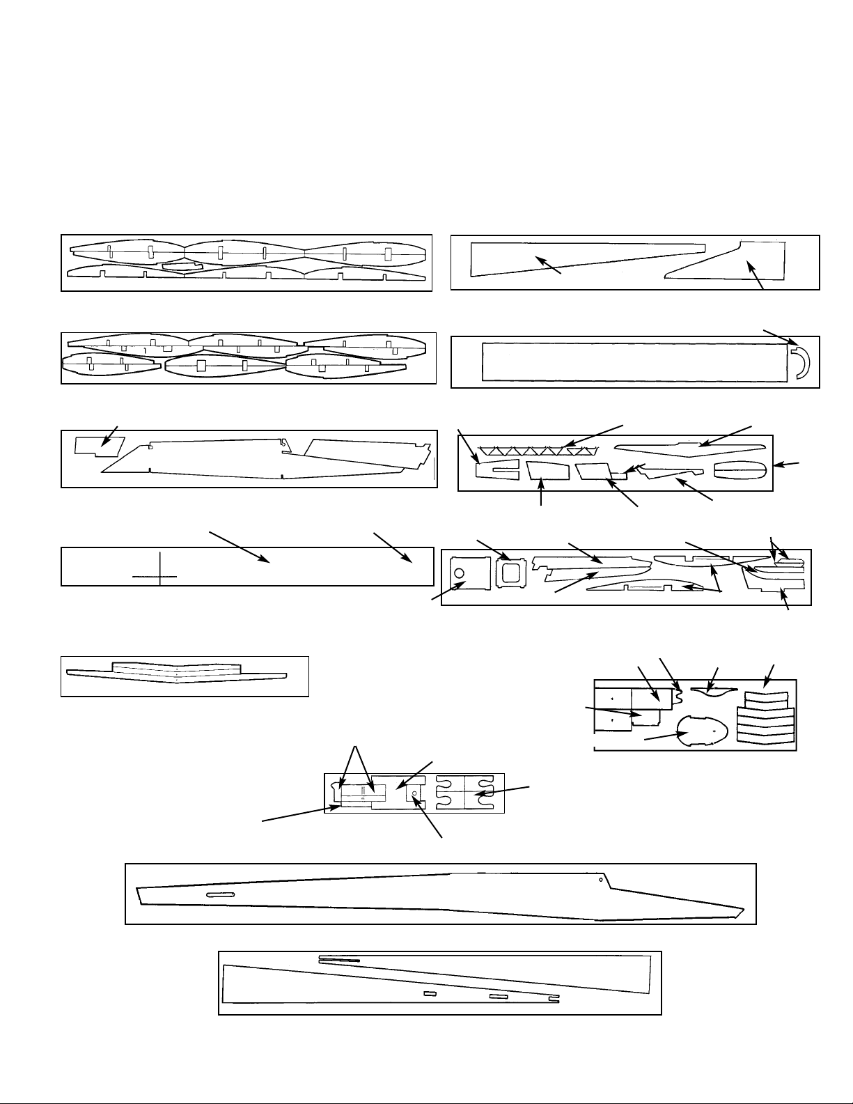
SHEET 4001 WING RIBS 5/64 x 2-7/8 x 24" 2 REQ’D.
SHEET 4002 WING RIBS 5/64 x 2-7/8 x 24"” 2 REQ’D.
D/CSHEET 5902 5/64 x 2-7/8 x24" 2 REQ’D.
D/C SHT. 4014 1/8x2-1/4x13" PLY 2 REQ'D
D/C SHT. 4012 1/16 x 3 x 24" 2 REQ'D.
D/C SHT. 4013 1/16 x 3 x 24" 2 REQ'D/
D/C SHT. 4009 1/8 x 2-3/8x17" PLY 1 REQ'D.
D/C SHT. 5903 5/64 x 3 x 24" 2 REQ'D.
D/C SHT. 5905 1/8 x 2-1/2 x 24" 1 REQ'D.
D/C SHT. 5906 5/16 x 2-1/2 x 24" 1 REQ'D.
D/C SHT. 5907 1/16 x 3 x 9-7/8" 1 REQ'D.
D/C SHT. 5904 3/16 x2-1/2 x 18" 1 REQ'D.
D/C SHT. 5901 5/64 x 3 x36" ” 2 REQ’D.
WING POLYHEDRAL
JOINERS
TAIL SKID
YOKE
BALLAST BULKHEAD
FIN PART #1
FIN PART #2
FUSE SIDE DOUBLER
FUSE BOTTOM SHEETING
COCKPIT FRONT FORMER
COCKPIT PLATFORM
COCKPIT REAR FORMER
BEVELING TOOL
WING GAUGE
MOTOR SWITCH MOUNT
JOINER CLAMPS
SERVO MOUNTING RAIL
FUSE SIDE
NOT NEEDED IN THIS KIT
INBOARD PANEL L.E. SHEETING
STAB CENTER PLATFORM
WING/TAIL GUSSETS
STAB L.E. JOINER
RUDDER TOP
DORSAL FIN
STAB TIPS
VERT.FIN BOTTOM
RUDDER BOTTOM
FRONT BULKHEAD
REAR BULKKHEAD
FIN PART #3
FIN PART #5
POWER POD RIB #1
BULKHEAD DOUBLERS
FIN PART #6
FIN PART #4
FUSE TOP
FUSE BOTTOM
FRONT FORMER
CANOPY REST
WING CENTER JOINERS
OUTBOARD PANEL L.E. SHEETING
MID-CENTER SHEETING
Page 5
END VIEW OF STRIP WOOD PARTS
BASSWOOD BALSA
FRONT SPAR
1/4 x 13/32”
REAR SPAR
1/8 x 3/8”
FRONT SPAR
1/4 x 3/8”
REAR SPAR
1/8 x 3/8”
1/4” SQUARE
17-7/8”
INBOARD L.E. = 20-3/4” LONG
OUTBOARD L.E. = 17-5/8” LONG
ELEVATOR L.E.
3/16 x 3/8”
ELEVATOR
TRUSS
5/64 x 3/16”
RUDDER T.E.
8-1/4” LONG
ELEVATOR.
20-3/4” LONG
INBOARD T.E. = 20-3/4” LONG
OUTBOARD T.E. = 17-1/2” LONG
HATCH RAIL
1/8” SQ.
INBOARD WING SPAR
OUTBOARD WING SPAR
WING LEADING
EDE (L.E.)
WING TRAILING
EDGE (T.E.)
PUSHROD
5
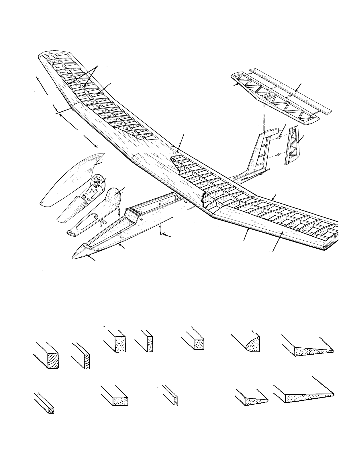
AIRPLANE STRUCTURE
NOSE BLOCK
CHIN BLOCK
TOW HOOK
WING ASSEMBLY
COCKPIT DETAIL
CANOPY
OUTBOARD
PANEL
RUDDER
HINGES
HORIZONTAL STABILIZER
TAIL ASSEMBLY
ELEVATOR
CENTER SHEETING
FUSELAGE
LEADING EDGE
LEADING EDGE SHEETING
TRAILING EDGE
COCKPIT PLATFORM
INBOARD PANEL
MAIN & REAR SPAR
RIBS
Page 6
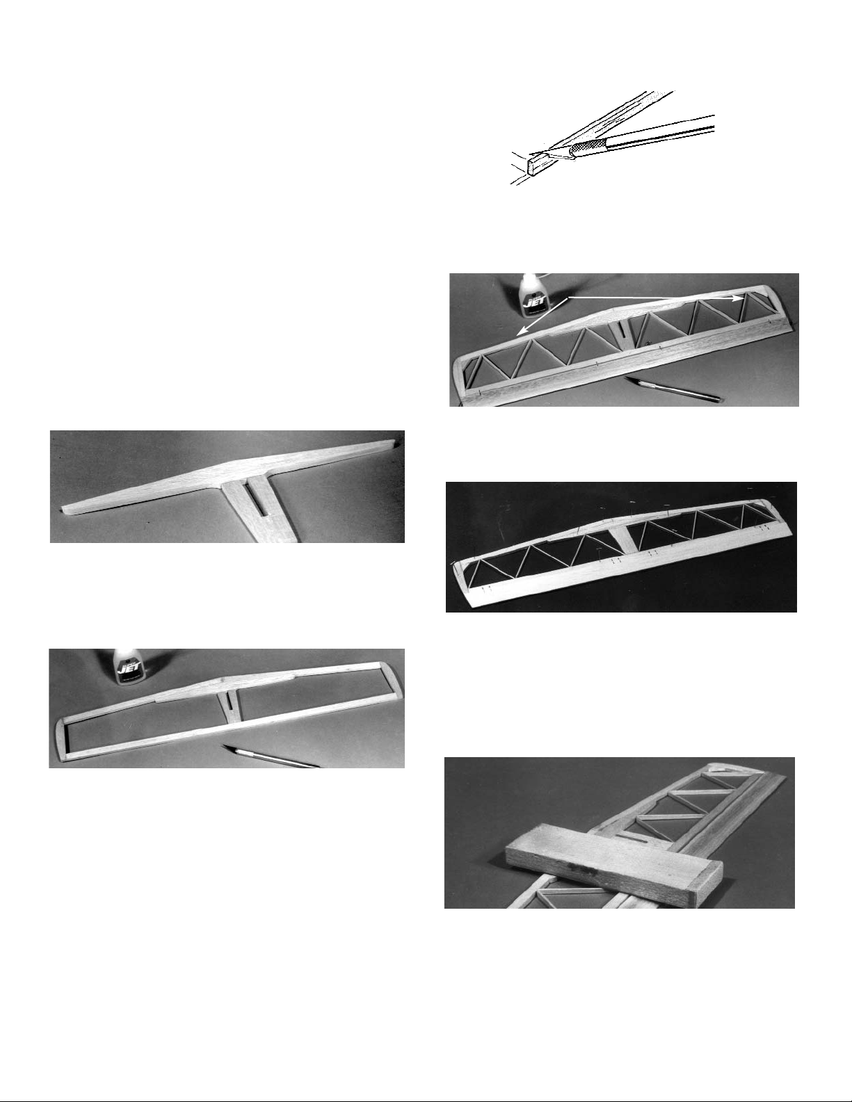
TAIL CONSTRUCTION
1. Collect the following items.
(4) 3/16 x 3/8 x21” BALSA PT. #4853
(1) 1-3/4 SQ. x 21” BALSA PT. #4696
(3) 5/64 X 3/16 X 24” BALSA PT. #4698
(1) 1/2” SQ. x 8-1/4” BALSA PT. #4701
(1) CENTERLINE MARKER PT. #1425
(7) SMALL FLEX-POINT HINGE PT. #1448
(1) FIN HINGE POST PT. #4560
(1) .034 ID / .064 OD x 36" TUBING PT. #5682
(2) D/C SHEET 5903 BALSA PT. #3403
containing fin parts #1 and #2
(1) D/C SHEET 5904 BALSA PT. #3404
containing: fin bottom, rudder,
dorsal fin, stap tips, stab L.E. joiner
gussets, stab center platform
(1) D/C SHEET 5907 PT. #3407
(1) D/C SHEET 5906 BALSA PT. #3406
containing: fin parts #3, #4, #5, #6
(2) D/C SHEET 4014 PLY PT. #3614
2. Lay the horizontal stabilizer portion of the plan
over the building board and cover with waxed
paper.
Buidling over the plan, pin in position and glue
the leading edge joiner to the center platform.
5. Still working over the plan, and using the tech-
nique shown above, cut 5/64 x 3/16” balsa
sticks to form stab trussing. Trim carefully to
size, so that each truss fits in place without
forcing. SAVE THE SCRAP MATERIAL!
6. When satisfied with the fit, glue in place.
Glue the gussets in place and allow the entire
stab to dry thoroughly.
7. Referring to the plan, mark the hinge locations
on the top of the trailing edge with a soft pencil.
Using 3 or 4 drops of Super Jet™, tack-cement
the elevator to the stab.
Carefully transfer the hinge location marks
onto the elevator.
3. Carefully cut two 3/16 X 3/8” balsa sticks to
form the stabilizer leading edge. Make sure to
exactly match the plan from the center mark to
the tips.
IMPORTANT! SAVE SCRAP MATERIAL FOR USE IN
CONSTRUCTING THE FUSELAGE.
Pin the pieces in position and glue at the cen-
ter joint.
4. Using additional 3/16 x 3/8” balsa sticks, con-
tinue building the stab outline by pinning and
gluing the trailing edge and stab tips in place,
as shown above.
GUSSET
8. Using a sanding block, flat sand the stab and
round the outer edges. Sand the elevator tips
to blend with the stab.
6
Page 7
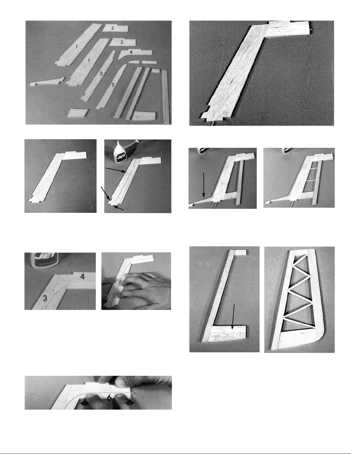
9. Carefully remove the die cut fin parts and light-
ly sand any rough edges.
10. Building over the plan, glue part #1 to part #2.
Place part #3 on top of part #1, making sure that
the notches are aligned and the leading edges
are flush. When the parts are aligned, glue in
place.
11. Position part #4 on top of part #2, as shown.
Then glue in place.
12. Add part #5 to the assembly, sandwiching the
1/16" outside diameter nylon tube in place
between part #3 and part #5.
Make sure the tube lies flat and that it extends
1/8" past the trailing edge (T.E.) of the fin.
Glue part #5 in place.
13. Glue part #6 in place, sandwiching the remainder
of the tube into the fin assembly.
14. Glue the remaining parts #1 and #2 to the fin
assembly and trim the nylon tube flush with the
trailing edge of part #2.
15. Glue the 3/16" D/C fin bottom and 3/16 x 1/2"
balsa hinge post to the fin assembly.
16. Cut the fin ribs from 5/64 x 3/16" strip balsa and
glue in place, as shown above right.
17. Glue the 3/16 D/C balsa top and bottom to the
3/16 x 3/8" rudder hinge post. Then glue the
shaped T.E. in place.
18. From 5/64 x 3/16" balsa, cut all trusses to size
and glue in place.
19. Flat sand the rudder/fin assembly, rounding the
fin L.E. and blending the rudder bottom with the
T.E.
7
1
2
3
2
1
5
1
GLUE DORSAL
FIN
BOTTOM
Page 8
WING CONSTRUCTION
IMPORTANT: YOU WILL BE BUILDING A RIGHT AND THEN A LEFT
WING. FOLLOW THE STEPS CAREFULLY TO AVOID CONFUSION.
1. Collect the following items:
(2) D/C SHT. 4001 (5/64” Balsa) PT. #3601
Contains: WING RIBS
(2) D/C SHT. 4002 (5/64” Balsa) PT. #3602
Contains: WING RIBS
(1) D/C SHT. 4009 (1/8” Ply) PT. #3609
Contains: WING CENTER JOINERS
(2) D/C SHT. 4012 (1/16” Balsa) PT. #3612
Contains: WING SHEETING
(2) D/C SHT. 4013 (1/16” Balsa) PT. #3613
Contains: INBOARD PANEL
L.E. WING SHEETING
(2) D/C SHT. 4014 (1/8" Ply) PT. #3614
Contains: GAUGES & CLAMPS
(4) BALSA SHEET 1/16x3x12” PT. #4600
(2) INBOARD T.E.LONG PT. #4688
(2) OUTBOARD T.E.SHORT PT. #4689
(2) INBOARD L.E. LONG PT. #4690
(2) OUTBOARD L.E. SHORT PT. #4691
(2) INBOARD MAIN SPAR Bass PT. #4692
(2) OUTBOARD MAIN SPAR PT. #4694
(2) INBOARD REAR SPAR Bass PT. #4855
(2) OUTBOARD REAR SPAR balsa PT. #4874
(1) 3/4 X 38” NYLON FABRIC PT. #9524
(1) 1 x 6” ALUMINUM STRIP PT. #1390
2. Working over the RIGHT INBOARD PANEL of
the plan, place a 1/4” x 13/32” basswood spar
main spar so that the spar end is aligned with
the wing center on the plan.
NOTE: If building the second half of the wing, you
will be working over the LEFT INBOARD
PANEL. DO NOT BUILD TWO RIGHT WINGS!
Hold the spar in place by cross-pinning
between the ribs at the circle locations shown
on the plan.
Using no pins, position the rear spar on the
plan.
8
4. Position the wing leading edge (L.E.) in place
over the plan and pin.
Secure the ends of both spars with pins, as
shown.
5. Remove the two #5 ribs nearest the wing cen-
ter.
Position and glue all remaining #5 ribs, as
shown on the plan.
IMPORTANT! IF BUILDING THE LEFT WING, PROCEED DIRECTLY TO STEP 10.
3. Align the notches in the wing trailing edge (T.E)
with those shown on the plan.
Using no glue, position the four #5 ribs as
shown above. Hook each rib over the main
spar and then over the rear spar, as you go.
NOTCHED END
NO NOTCH
DO NOT GLUE THESE
RIBS AT THIS TIME
Page 9
6. Noting that the rear spar joiner has a tapered
end, fit the front and rear spar joiners into position as shown.
Glue the joiners to the spars and, referring to
the plan, hold in place with the gauges. Allow
to dry.
7. Taking care to make sure that the grain of the
sheeting will run parrallel to the spars, L.E. and
T.E., cut t hr ee 3-1/4” pieces fro m a 1/16 x 3 x
24” balsa sheet.
8. Slide one piece of sheeting forward until it just
touches the L.E. Gently holding the sheet in
position, mark the spar location on both of the
rear corners of the sheet.
Remove the sheet from the wing and, using a
metal straight edge, carefully trim the sheeting
so that, when the piece is laid flat, it just fits
between the L.E. and the spar.
MARK MARK
MATCH WING GAUGE
POSITIONS TO PLAN
REAR SPAR
JOINER HAS
TAPERED ENDS.
WOOD GRAIN MUST BE PARALLEL TO SPARS, L.E. AND T.E.
9
Fit the first sheeting piece between the spars
and, holding it flat to the building board, Super
Jet the edges to the spars.
Install the other two sheeting pieces in the
same manner.
9. Position ribs #2, 3, and 4, making sure to align
the rib fronts over the front guide lines on the
plan.
When satisfied with the alignment, glue to the
L.E., the bottom sheeting, the spars, and the
T.E.
10. Pin the outboard main spar in place over the
plan. Then set the rear spar and the T.E. in
place.
IMPORTANT! The outboard T.E. has no notch at one
end. This unnotched end must be at the polyhedral
joint, as shown.
POLYHEDRAL
JOINT
NOTCHED
END
Following the same procedure, trim and fit two
more sheeting pieces for the bottom center
section.
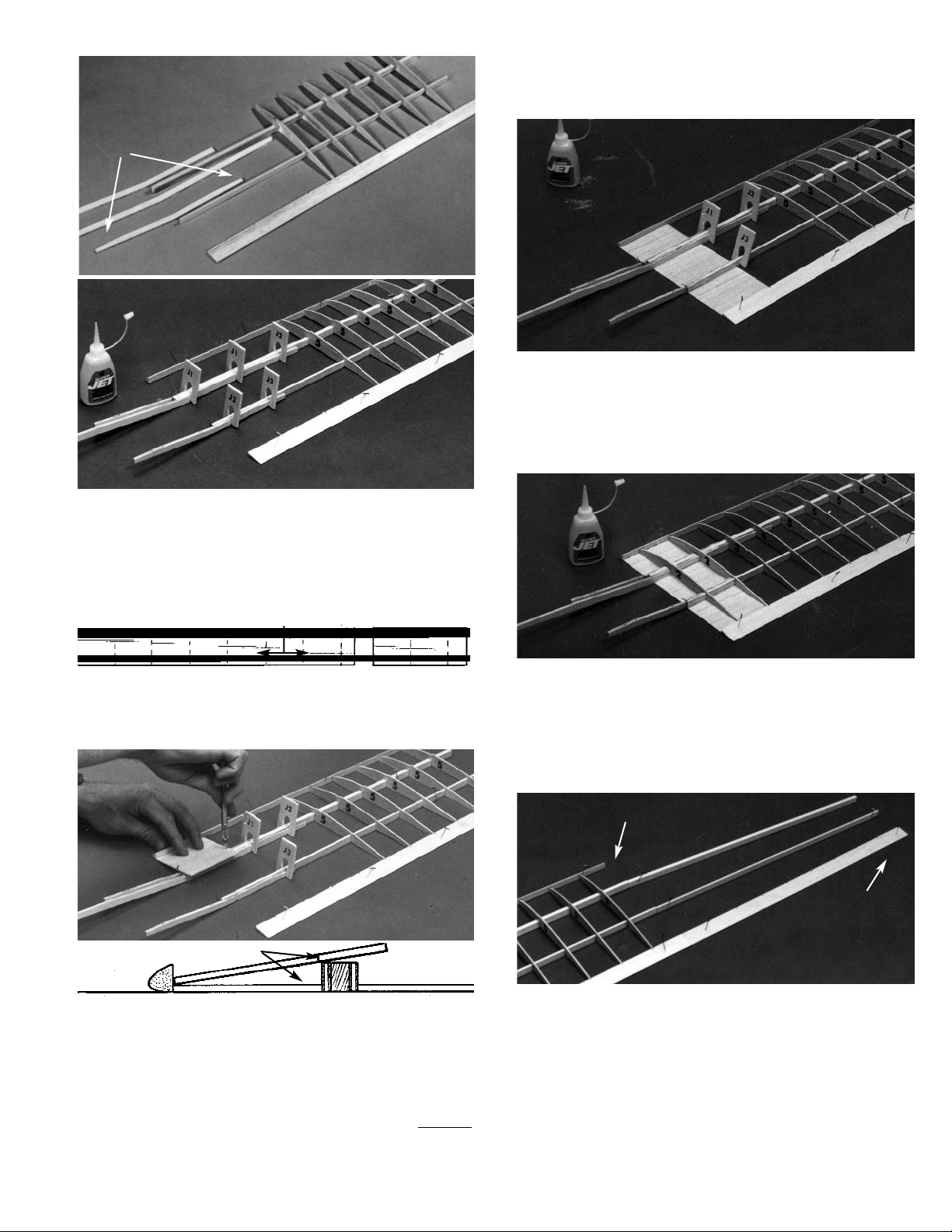
Page 10
11. Using no glue, set ribs #7, 9,12, and 15 in their
respective T.E. notches, hooking them over the
spars as you go.
Making sure the T.E. and the ribs are correctly
aligned over the plan, pin in place.
Glue the ribs to the spars and the T.E.
12. Pin the outboard L.E. in place and glue it to the
ribs.
13. One at a time, position and then glue the
remaining ribs #8 through #14 in place. Let dry
thoroughly.
NOTE: IF YOU ARE CONSTRUCTING A ONEPIECE WING, CONTINUE AT STEP 14. IF YOU
WISH TO BE ABLE TO REMOVE THE WING TIP,
REFER TO THE FOLLOWING OPTIONAL
INSTRUCTIONS.
DO NOT GLUE
IN THIS AREA
10
NOTE: The materials needed to make the wing tip
removable are NOT INCLUDED in your kit.
Necessary templates for this option are found in
the upper right corner of the wing half of the plan.
Follow these steps ONLY IF YOU WANT TO BE
ABLE TO REMOVE THE WING TIPS. Otherwise,
continue at Step 14.
REMOVABLE TIP OPTION
A. Collect the following items:
1/8” x 3” x 18” HARD BALSA SHEET
3/32” x 12” MUSIC WIRE
3/32 I.D. x 6” BRASS TUBE
3/34” VINYL ELECTRICAL TAPE
SANDING
BLOCK
SANDING
ANGLE TEMPLATE
POSITION & GLUE
SCRAP PLY TO BACK SO
THAT FRON MATCHES
WITH TEMPLATE.
B. Make a sanding block from 1/8” scrap plywood,
using the SANDING ANGLE TEMPLATE from
the plan. Make sure to establish tthe proper
sanding block angle, as show above.
C. From the 1/8” hard balsa sheet, cut four NEW
#6 ribs. DO NOT USE THE #6 die cut ribs
that are included with your kit.
D. Remove the pins from the inboard panel and
use the sanding block to gently sand the polyhedral ends of the spars, the L.E., and the T.E.
to insure uniform vertical surfaces.
E. Referring to Step 14 for correct use of the die-
cut wing gauges, raise the inboard wing panel,
as shown.
3/32” I.D. TUBE 3/32” WIRE
INBOARD PANEL
F. Position the 3/32 x 3” wire on the back of the
spars, as shown.
Page 11

Referring to the TIP OPTION on the plan, care-
fully groove the spars for the wire and for the
brass tube.
G. Tack-glue the WIRE to the OUTBOARD SPAR
and the BRASS TUBE to the INBROARD
SPAR.
Plug the wing panels together and make cer-
tain the wing structures butt evenly at the polyhedral joint. If adjustments are needed, take
the panels apart and rework the grooves slightly.
When satisfied with the fit of the joint, glue the
metal parts in place.
H. With the wing panels plugged together, posi-
tion the new #6 ribs at the polyhedral joint. The
ribs should be tilted slightly toward the outboard panel, so that they match the spar angle.
TAKING CARE TO NOT GLUE THE WING
PANELS TOGETHER, carefully glue the ribs to
their respective wing panels.
I. Unplug the wing panels. Then, working on first
the inboard panel and then the outboard panel,
wrap a about 2” of 3/4” wide nylon fabric
(included in your kit) around each of the spars
to secure the wire and brass tubing.
Saturate the nylon fabric with Super Jet or Jet
Epoxy, to create a sturdy bond.
WRAP NYLON AROUND SPARS,
TUBES, AND WIRES
11
J. Add gussets (D/C Sht. 4006) at the L.E. and
T.E., as shown above.
NOTE: This completes the removable tip option construction for the first wing half. When working on the
second wing half, you again will follow the above
instructions. After the wing parts are covered, the
removable panels are fastened to the inboard wing
sections using vinyl electrical tape. This tape holds
firmly, yet can be removed without damaging the covering material.
NOW PROCEED DIRECTLY TO STEP 19.
14. With the outboard panel still pinned down, raise
the inboard panel and support it with the wing
dihedral gauges under the first rib #5 location, as
shown on the plan.
IMPORTANT: The end of the gauge stamped “A” must
be up. Hold the gauges firmly in place by tack-cementing, clothespins, etc.
Carefully inspect the panel joint to make sure all
of the end pieces of the inboard panel fit tightly
to those of the outboard panel. If one part protrudes too much, sand slightly for a better fit.
WARNING: always sand just a little at a time
, so
that you do not remove too much wood. You
may find it helpful to use the sanding tool
described in the removable tip option.
15. TEMPORARILY install the diihedral joiners on
each side of the spars. Use die-cut clampls to
hold in place.
When satisfied with the fit of the inboard and out-
board panels, pin in place, as shown above.
16. Remove the dihedral joiners and apply a liberal
bead of Super Jet to all joints of the L.E., spars,
and T.E.
Quickly apply glue to the joiners and immediate-
ly reinstall. Use the clamps again to hold both
joiners tight to the spars. Allow to dry.
IMPORTANT: "A" AT TOP
MATCH GAUGES WITH PLAN
17. Lay out two #6 ribs, and two doublers, as
shown.
Glue rib doubler #6a to each rib, taking care to
make on left and one right rib.
18. Position rib #6 so that it aligns with the joints in
the L.E., the spars, and the T.E. Make sure that
the doubler is facing out, toward the outboard
pannel. When satisfied with the fit, glue in
place.
Referring to the plan for location, glue gussets to
rib #6, the L.E., and the T.E.
Page 12

If this is your first wing half, set it aside and begin
building the left half of the wing.
MAKE SURE YOU WORK OVER THE LEFT
WING
PORTION OF THE PLAN. DO ONLY STEPS 1
THROUGH 5 AND 10 THROUGH 19 FOR THE LEFT
INBOARD PANEL.
When both halves are complete to this point, continue with Step 20.
12
Fold the sheeting back down over the ribs and
hold in place until dry.
Apply a bead of glue to the L.E./sheeting joint,
in the areas between the tape. Allow to dry.
HINT: Using Jet Set™ accelerant speeds this (and
many other) gluing processes.
When the joint is firm, remove the tape and
apply glue to the remaining unglued areas of
the joint.
Lift the sheeting, as shown, and apply Super
Jet™ along the top of each rib where it will
contact the sheeting.
19. Set the outboard L.E. sheeting in place, align-
ing the inboard edge of the sheet with the joint
between rib #6 and the #6a doubler. When
correctly positioned, tape the sheeting to the
L.E.
20. Trim off excess spar material extending beyond
the #15 ribs (wing tip ribs)
21. Glue trip strip to the #15 ribs, as shown.
Carve and sand balsa tri-strips, so that they
match the top contour of the wing tip ribs.
22. Still working over the plan, pin down the left
inboard panel.
Slide the right inboard panel up tight next to the
left inboard panel, engaging the joiners with the
spars, as shown above.
23. Raise up the right inboard panel, supporting it
with the dihedral gauges at the oute
rmost rib
#5 position.
IMPORTANT! The ends stamped “B” must be up.
Page 13

24. Remove the clamps and insert pins between
the spars and the joiners.
Apply Super Jet™ between the parts and then
remove the pins, allowing the pieces to come
back together. Immediately replace the clamps
to hold the joiners tight on the spars. Let dry
thoroughly.
25. When the glue has dried, remove all clamps
from the spars.
Cut three 3-1/4” pieces of bottom sheeting from
the remainder of the 1/16” balsa sheeting.
13
Examine the center joint for good fit and align-
ment of the L.E., the spars, the joiners, and the
T.E. Adjust as necessary, sanding slightly to
make the pieces fit together.
Temporarily install the clamps to hold the join-
ers tight on the spars.
When satisfied with the fit, pin the wings togeth-
er.
26. Glue the remaining ribs #2, #3, and #4 in place.
Glue together two #1 ribs to make a single, dou-
ble-thickness rib.
GLUE ALL JOINTS
BEFORE COMPLETEING SHEETING
Trim to fit between the spars, just as was done
in Step 7. When satisfied with the fit, glue in
place.
Glue the L.E., the bottom sheets, and the T.E.
together at the center joint.
27. Following the same procedure used in Step 19,
install the inboard L.E. sheeting.
Position this doubled #1 rib at the center joint,
making sure it aligns with the spar center joint,
the L.E., the bottom sheeting, and the T.E.
Glue in place.
NOTE: Make sure all joints are well-glued before completing the center sheeting.
When the L.E. sheeting is dry, install the die-
cut, tapered center sheeting.
From plain 1/16 x3 x 12” balsa, cut and fit the
remaining rear sheeting piece.
Remove all pins and gauges and complete the
sheeting of the right wing.
Page 14

28. Using 240 grit (fine) sandpaper, flat sand the
entire wing to blend the surfaces and remove
high spots. Take care not to sand too much, or
the sheeting will be thin and weak.
Cut the 1 x6” aluminum strip into two 3” pieces
and sand lightly for better glue adherence.
ALUMINUM
SHEET
14
Apply a bead of Super Jet™ to one half of one
of the aluminum pieces and glue it to the bottom of the wing, as shown above.
When dry, apply glue to the other half of the
strip and wrap it around the T.E.
Repeat this procedure for the other aluminum
piece.
29. Cut a piece of 3/4” wide nylon long enough to
wrap completely around the wing with a small
overlap.
Apply a spot of Super Jet™ on the wing bottom
at the center joint.
Immediately stick one end of the nylon strip to
the wing and let dry until it is firmly glued to the
balsa.
IMPORTANT!
The following procedure must be done in a WELL-
VENTILATED AREA.
Before continueing, protect fingers with a plas-
tic bag or plastic wrap.
Starting with the bottom of the wing, apply a
squiggle of glue along the wing joint and lay the
nylon strip over it.
Rub the glue thoroughly into the nylon strip.
Continue applying the nylon strip around the
L.E., across the top of the wing, around the
T.E., and finally overlapping where you started
on the wing bottom.
Unless you have made the removable wing tip
option, repeat the above procedure, installing
nylon fabric at the polyhedral sheeting joints.
THIS COMPLETES THE WING ASSEMBLY. SET
ASIDE UNTIL IT IS TIME TO COVER.
Page 15

15
FUSELAGE CONSTRUCTION
1. Collect the following items:
(2) D/C SHT. 5901 FUSELAGE SIDE PT. #3401
(1) BALSA CHIN BLOCK PT. #4568
(1) BALSA NOSE BLOCK PT. #4569
(5) 1/8” SQ. x 36” BALSA STICK PT. #4705
(1) D/C SHEET 5902
Contains:Fuse top and Fuse bottom PT. #3402
(2) D/C SHEET 5903
Contains: Fuse Doubler PT. #3403
(1) D/C SHEET 5905
Contains Formers & fuse bottom PT. #3405
(2) D/C SHEET 4014 PT. #3614
(1) D/C SHEET 5907 FORMERS PT. #3407
(1) 1/8 x1/4 BALSA STICK PT. #4561
(2) SCREW EYES PT. #1194
(1) 1/8 x7/8" DOWEL PT. #1736
(2) 3/16 x 3-7/16 DOWEL PT. #1748
(1) HATCH HOLD DOWN PT. #4570
(1) TOWHOOK PT. #5811
(1) CANOPY PT. #1569
(1) COCKPIT INSERT PT. #1570
Carefully remove the die-cut pieces and lightly
sand any rough edges before beginning
assembly.
3. Glue an 1/8" sq. balsa stick to the front of the
fuse side assembly.
2. Place the fuse side and fuse side doubler
together, using the 3/16" diameter dowel to
align the two pieces correctly.
When satisfied with the fit, glue the pieces
together.
Trim the stick flush with the edges of the dou-
bler, as shown above.
5. Measure 1-1/2" back from the read end of the
fuse side and make a mark. Trim the 1/8"
square balsa stick to this point and then glue
the stick in place.
4. Again using 1/8" sq. balsa sticks, fit and glue to
the top and bottom of the fuselage side. Do
NOT GLUE at rear of fuse.
Trim the 1/8" balsa pieces flush with the fuse
front.
Page 16

6. From the wood parts bag, take the 1/8 x 1/4"
balsa wing rest and place it flush with the front
bulkhead notch, as shown above.
Making sure it is flush with the top of the fuse
side, glue in place.
7. Using a piece of 1/8" sq. balsa, butt the end
into the wing rest.
Measuring 1-1/2" in from the end of the fuse
side, trim the 1/8" balsa stick and glue in place.
8. Repeat the above steps to contruct a second
fuse side. Be sure you build a right and a
left side.
NOTE: Before moving on, make sure all joints are
flush and the 1/8" strips are flush with the
edges of the fuse side, all around. Sand if
necessary.
9. Take the left fuse side only and punch out the
exit hole, as shown.
10. Glue the D/C bulkhead doubler to the bulkhead.
11. With the fuse sides together, doublers to the
inside, pin a piece of 3/16" balsa scrap between
the sides at the back end of the fuse.
16
Glue the cut stick in place.
Page 17

17
12. Spread the fuse sides and insert bulkhead tabs
into the locating slots in the fuse.
NOTE: Make sure doublers face aft.
13. Hold assembly together with rubber bands.
Make sure the fuse is perfectly straight.
When you are satisfied with the alignment,
glue as shown.
14. Trim two 1/8 x 1/4" balsa sticks to fit along the
top of the formers, acting as doublers.
When satisfied with the fit, glue these balsa
doublers in place, as shown.
15. Position the 1/16" plywood nose former, using
a rubber band to hold it in place.
Glue securely in place.
16. Using the plan, if necessary, pin the fuse to the
building board, making sure the alignment is
straight and correct.
When satisfied with the alignment, glue the
1/16" rear top sheeting in place. Allow to dry.
17. Unpin the fuse from the building board and turn
it over, so that it is bottom side up.
Glue the 1/2" balsa chin block to the bottom of
the fuse, fitting it to the nose former as shown.
18 Next, glue the 1/8" D/C balsa bottom sheeting
in place.
WING REST
COCKPIT AREA
BALSA DOUBLERS
Page 18

18
19. Trimming as necessary, fit the remaining D/C
1/8" balsa sheeting in place, making sure the
sheeting is even with the center of the bulkhead.
When the fit is correct, glue the D/C 1/16" balsa
bottom sheeting in place and hold until dry.
IMPORTANT! Do not allow the fuselage to twist. Pin
down, if necessary.
20. When the sheeting has dried, glue the nose
block to the plywood nose former, as shown.
21. Turning the fuse right side up, fit the 1/16" ply-
wood canopy rest in place and glue.
22. Taking off small amounts at a time, carefully
shape the front of the fuse to fit the top view
profile shown on the plans.
23. Pin an 1/8" sq. balsa strip to the bottom edge of
the outer fuse side, following the curve of the
fuse bottom, as shown.
Remove the excess wood from the chin block,
so that it matches the fuse bottom sheeting.
Draw a line along the pinned balsa strip, mark-
ing its location.
Remove the balsa strip and sand to the line.
Page 19

19
24. Draw a centerline lengthwise along the bottom
of the fuse.
Rough shape the front of the fuse, using the
centerline as a reference of symmetry.
Sand to a finished shape.
25. Drill a 1/8" diameter hole about 3/4" deep at the
D/C drill point. ???
Insert the 1/8" diameter dowel in the hole, leav-
ing 1/4" exposed, and glue in place.
26. Using medium sandpaper, bevel the edges of
the cockpit platform so that it fits into the fuse.
27. Place waxed paper behind the cockpit platform
joints and then pin the platform onto the fuse.
Glue the formers onto the platform, as shown.
28. Making sure you remove only scrap plastic,
cut two pieces of plastic from the canopy
excess and place them between the fuse and
the canopy platform. This will raise the platform to allow for the thickness of the canopy.
Sand the front former flush with the nose block.
When satisfied with the fit of the pieces,
remove the plastic scraps.
Next, bevel the front and rear formers so that
they lie against the fuse and flat on the cockpit
platform.
Page 20

20
29. Position the 1/16" D/C plywood yoke snugly
under the hatch pin and glue in place.
30 Trim the plastic cockpit detail to fit onto the plat-
form.
Glue the plastic detail in place and trim any
excess flush with the platform edges.
31. Apply the instrument panel decal (see decal
instructions in Final Assembly section.)
Fit the canopy in place, rough trimming it to
size.
Making sure the platform remains flat, glue the
canopy to the platform.
Trim excess plastic flush with the platform bot-
tom and front. Trial fit the back of the canopy
onto the wing. The final fitting will occur when
the wing is mounted on the fuse.
32. Glue the two 1/16" D/C plywood tow hook
mounting plates together.
Fit the laminated mount in place, as shown on
the plan.
33. With the punch marks facing up, drill a 3/32"
diameter hole through the plywood mount and
the balsa fuse bottom.
Trace the tow hook washer on the fuse bottom
and cut in the washer clearance, as shown. Be
sure to go through the balsa and down to the
plywood layer.
Page 21

21
COVERING & FINAL ASSEMBLY
ASSEMBLING FIN TO FUSELAGE
CUTTING HINGE SLOTS
1. Remove the 3/16" balsa spacer from the rear
end of of the fuse.
Insert the nylon guide tube attached to the fin
into the middle slot on the rear top of the fuse,
and guide it completely through the fuse.
FUSE TOP
NYLON TUBE
2. Slide the fin down, inserting the rudder post
into the slot at the end of the fuse.
RUDDER POST
3. Tilt assembly forward and snap the two fin tabs
into the remaining slot.
If satisfied with the fit, apply glue to tabs and
the top of the fuse and glue the fin in place.
Lay the fuse over the plan and check for cor-
rect alignment between the wing rest and the
top of the fin. Trim to match, if necessary.
4. Slide the 1/16" D/C ply tailskid into the slot on
the bottom of the fuse and glue in place.
1. Take the tack-glued stabilizer assembly and
separate the elevator from the stab.
Place the pieces on the plan and mark the
hinge locations onto the stab, the elevator, the
rudder and the fin.
2. Using a CGM centerline marker, mark a center
line along the entire length of the elevator and
the rudder.
Next, mark a centerline at the hinge locations
on the fin and the stab.
3. Using a 1/16" diameter drill bit, bore through at
the hinge marks.
Page 22

22
4. Slot each side of the hole for hinge clearance.
Test fit the hinge, so as to not cut too much.
The hinge fit should be snug.
5. Slide the hinge in, but do not glue at this time.
6. Attach the rudder to the fin and the elevator to
the stab and check the fit. Then disassemble
and remove the hinges.
BEVELING RUDDER & ELEVATOR
NOTE: This kit contains D/C ply parts for two tools, but
only one is used to construct the aircraft.
1. First glue the narrow strip to the handle. keep-
ing it square, as shown below.
2. Cut a strip of 100-200 grit sandpaper to fit tool
and tack-glue in place, as shown above.
Then, glue a wide strip to the handle and the
narrow strip, again keeping things square.
3. Tape the trailing edge of the elevator and the
rudder to the work surface.
Using the beveling tool as shown, sand the
leading edges to the center line.
Turn the parts over and repeat the beveling on
the other side of the leading edges.
WHEN COMPLETE, THE
BEVELED SURFACES
SHOULD LOOK LIKE
THIS
COVERING THE AIRCRAFT
INTRODUCTION
There are several ways to cover the frame of a model
airplane. Years ago, the open framework of most airplanes was covered with a combination of tissue (or
silk) and dope; the solid structures were painted.
Today, most models are covered with polyester films
that resemble either a painted finish or a fabric finish.
These films are easy to apply and actually increase the
strength of the aircraft. The easiest way to finish your
model is to cover it in one color, but as you become
more proficient, you will devise fancier trim schemes.
The following instructions describe the general procedure for covering a model. However, it is important to
carefully read the instructions that come with the
film, as different products are applied in somewhat
different ways.
Page 23

23
PREPARATION
Any irregularities in the wood surface will show on the covering, so
a good covering job MUST be
preceded by careful sanding, filling of nicks and dents (we recommend JET Model Mate™ balsa
filler), and then more sanding. For
the final sanding, use fine sandpaper (240-320 grade) and a
sanding block.
IMPORTANT: Before starting, it's a good idea to do a
lay out of the covering pieces you will need to cut from
the covering rolls, so that you make efficient use of
your material. BE SURE TO LEAVE EXTRA MATER-
IAL (1½" to several inches) around all pieces, so you
will have plenty of covering to go around the edges of
each section.
Generally, one first covers the wing, then the tail, and
finally the fuselage. Other small parts (such as the
hatch) are covered separately.
Set the covering iron to the proper temperature. Test it
by laying a small strip of covering over a scrap piece of
balsa and firmly pressing with the iron. Make sure the
iron is hot enough to activate the adhesive, but not so
hot that it burns the covering.
COVERING THE WING
Using a fresh model knife blade or razor blade, cut a
piece of covering material at least 1" larger than onehalf of the inboard wing bottom panel.
Remove the protective backing paper and lay the covering over the bottom of the wing, making sure there
is enough excess material for wrap-around at the L.E.,
T.E., and wing tip.
HINT: Leave a minimum of 3" excess at the wing
tip.
For inside corners, follow the instruction that come with
your covering, as different materials may require slightly different techniques.
Using your iron, secure the covering to the wing.
Shrink the covering tight according to instructions.
Neatly trim off any surplus.
Following the same procedure, cover the remainder of
the wing bottom and then cover the wing top. Be sure
to overlap all seams adequately, as there must be sufficient overlap to allow for the shrinkage.
OVERLAP COVERING AT
SEAMS.
SEAL INBOARD PANEL FILM TO
SIDES OF RIBS. DO NOT SHRINK
INTERIOR AREAS UNTIL WHOLE
WING IS COVERED.
AFTER ALL EDGES AND COLOR JOINTS ARE SEALED,
SHRINK ENTIRE WING COVERING
To detect warp,.set each section of the wing on a flat
surface and make certain the panel sits flat. To counter
any warp, twist panel slightly in the direction opposite
to the warp and hold this position while gliding the iron
over the covering to re-tension the structure. Repeat
process until the panel is true. NOTE: The T.E. of the
wing tip will rise up about 1/4" from the flat surface.
1/4" WASHOUT
POLYHEDRAL JOINT
TRUING THE WING & SETTING WASHOUT
IMPORTANT: After the wing has been covered, you
must check to make sure it is free of warps. This is a
very critical step and should not be rushed or
omitted.
COVERING THE TAIL & FUSELAGE
Cover all tail components (the stabilizer, the elevator,
the fin, and the rudder), following the same procedure
as with the wing. The component pieces should each
be covered separately, before assembly. Then, the
covering should be carefully removed from the areas to
be glued, so that a strong WOOD-SURFACE-TOWOOD-SURFACE adhesion is achieved.
Cover the fuse bottom, sides, and finally the top, again,
making sure the pieces are large enough to allow for
overlap.
IMPORTANT: Once the tail sections have been covered, and while the hinge locations are still fresh in
your memory, IMMEDIATELY slit the covering to
open up the hinge slots. (Refer to the plan for help
in locating the hinge slots.)
Page 24

24
After locating and opening the hinge slots, insert and
glue a hinge into each of the stab slots. Let the glue
wick into the slots and allow to dry. Then, attach the
elevators by inserting the other half of each hinge into
the elevator slots. Again, glue and allow to dry.
Repeat this procedure to attach the rudder to the fin.
When the glue has dried, firmly pull at each hinge location to make sure the bond is secure. FAILURE TO
FIRMLY INSTALL HINGES CAN LEAD TO LOSS OF
CONTROLL AND A CRASH. Periodically check control
surfaces to make sure the bond has not weakened.
Clean the model surfaces thoroughly before applying
decals.
Cut the decal sheet into sections, as needed. Fold the
decal in half, front to rear. Then open at the fold and
lay the decal out flat. The protective backing will bubble away from the decal at the fold location.Using a
scissors, cut the backing along the bubble, removing
about a 1” wide strip of backing. Carefully position the
decal on the model and, working from the center out,
rub the decal down while peeling off the backing.
It is also possible to make custom decals. Special cutting machines, hooked up to computers, allow one to
create almost any design for application on the model.
APPLYING DECALS
INSTALLING HINGES
CONSTRUCTING THE RUDDER PUSHROD
SIDE VIEW
12" WIRE
1/14" SQ. x17-7/8" BALSA PUSHROD
10" THREADED ROD
TOP VIEW
1. To construct the rudder pushrod, place the 10”
threaded rod over the plan, with the threads on
the snap link location.
Following the drawing on the fuse, bend to the
shape shown.
Next, carefully bend the non-threaded end at a
right angle and cut off the excess, leaving
about 3/16" which will fit into the wood.
2. Taking the 1/16 x12" wire, measure 3/16" from
one end and again make a right angle bend.
3. Place a 1/4" square balsa pushrod over the
plan and trim to size. if necessary.
Make a pencil mark 1" from each end.
Using a 1/16" drill, make a 3/16" deep hole at
each mark.
4. Using the threaded end of the 10" wire, make
grooves in both ends of the balsa rod, so that
the wire can be recessed into the wood.
5. Insert the bent end of each wire into the drilled
holes each end of the balsa pushrod.. Then,
glue the two wires in place.
6. When the glue has dried, use sandpaper to
round the corners and taper both ends of the
balsa pushrod.
Referring to the above drawings, bind the wires
to the wood with strong thread and re-glue the
entire area.
USING ROD
THREADS, FILE A
SLIGHT RECESS.
1"
3/16"
TAPER AND WRAP
WITH THREAD. THEN
COAT WITH GLUE.
Page 25

25
1. Cut the covering at the pushrod exit location on
the left side of the fuse. Install the nylon
pushrod exit guide and glue in place.
2. Referring to the plan, mark the location of the
rudder control horn.
Without attaching the snap links, Insert the
pushrod into the fuse at the wing rest area and
going back to the rudder. Make sure the threaded rod heads straight to the control horn location. If it does not, make any necessary adjustments.
Move the pushrod back and forth to simulate
the servo action. Remove the pushrod for
adjustment, if necessary, to achieve a smooth
operation.
TO OPEN, INSERT BLADE OF SCREW
DRIVER AND TWIST.
ALLOW ABOUT
1/8" OF THREAD
TO PROUDE
3. When satisfied with the installation of the
pushrod, install the mini-snap link onto the
threaded end of the pushrod. Use a screw driver blade to open the link. Holding the pushrod
wire with a pliers, twist a mini-snap onto the
threaded rod, so that the rod can be seen in the
center of the snap link.
4. Again referring to the previously marked control
horn location, install the control horn on the
rudder.
Adjust the pushrod, as necessary, and connect
the mini-snap to the 2nd closest hole to the
hinge.
INSTALLING PUSHROD
WING/FUSE ALIGNMENT
1. Position wing dowels so that they protrude
equally out of both sides of the fuse and glue in
place.
2. Using #64 rubber bands, mount the wing on the
fuse. Then, measure carefully from the fuse
sides out to the polyhedral breaks (arrows "A"),
making sure that the wing is centered.
Next, measure from the polyhedral breaks to
the back end of the fuse. Mark the wing and
the fuse with matching line-up points (colored
tape or washable marker).
3. Fit the stab onto the top of the fin, making sure
the alignment is square.
Trace the area where the stab meets the fin
and carefully remove the covering on the inside
of the trace lines and on the top of the fin. Do
not cut into the wood and keep 1/8" inside
the trace lines. Then epoxy the stab to the fin.
4. Reinforce the structure by gluing 5/16" triangle
stock under the stab, on each side of the fin.
TRI STOCK
#2-56 x 1/2" SCREWS
NUT PLATE
CONTROL HORN
Page 26

26
5. Referring to the plan, mark the location of the
elevator control horn on the elevator.
6. Snap a pushrod connector body on the last
hole of the elevator control horn.
Slide the stranded brass cable through the
nylon guide tube and through the hole in the
connector body, as shown above.
7. Tighten the set screw with the cable extending
through about 1/4" past the connector body.
8. Return the control horn to the previously
marked spot on the elevator and screw in
place.
Grasp the servo end of the cable and work it
back and forth, making sure that the movement
is smooth.
INSTALLATION OF THE TOW HOOK &
CANOPY HOLD-DOWN
1. Install the tow hook, as shown above.
TOW HOOK
4-40 HEX NUT
#4 WASHER
2. Glue a brass screweye mount to the canopy
platform and fuselage bottom.
Install the screweyes and rubber band for
canopy hold-down.
Page 27

27
MOVING STICK RIGHT MOVES THE RUDDER RIGHT 1-1/2"
MOVING STICK LEFT MOVES THE RUDDER LEFT 1-1/2"
MOVING STICK FORWARD (AWAY FROM YOU) MOVES ELEVATOR DOWN 3/8"
MOVING STICK BACK (TOWARD
YOU) MOVES ELEVATOR UP 3/8"
RADIO INSTALLATION
NOTE: Before installing the radio, read and follow the
instructions included with your radio. Also make sure
the batteries are fully charged and the pushrods are in
place and connected to the control horns. The wires at
the front end of the pushrods should have excess
length, reaching close to former #2.
ASSEMBLE & TEST THE RADIO
BEFORE INSTALLATION
1. Move the control stick from side to side. Apply
tape (on which you can write) to the receiver
plug which goes to the servo that moves. Mark
this wire "RUD." (If your receiver doesn't have
separate plugs coming from it, but does have
places for the servos to plug in, apply the tape
nearby, so that you can mark "R" opposite the
appropriate plug-in location.
2. Move the control stick up and down (away from
you and towards you). Mark the appropriate
plug or plug-in location "ELEV" or "E."
Note that the servo functions are determined by where
they are plugged into the receiver. Be sure to assemble them the same way each time, so that the servos
give you the proper responses.
INSTALLING THE RADIO
1. With the pushrods installed, tape the pushrod-
wires beneath the wing rest strip, so they will be
out of the way.
Insert the soft rubber grommets supplied with
the radio into the mounting holes of the servos.
Measure from the bottom of the servo to the
underside of a grommet and add 3/16" to this
measurement. The total is the height from the
fuse floor to the top of the servo rail.
2. Mark the inner sides of the fuselage at the cor-
rect location for the servo rails.
3. Notch one of the rails so that the cables will
clear the area as they exit from the servo. This
will be the forward rail.
Using either Super Jet or Jet epoxy, glue the
forward rail in place.
4. Placing one servo on the forward rail, deter-
mine the location for the back rail, allowing
approximately 1/16" clearance, so that the
servo can be removed easily.
Glue the rear rail in place.
5. Place both servos in position, with approxi-
mately 1/16" between them, and mark through
the grommets for the location of the servo
mounting screws. Remove the servos.
Using a 1/16" drill bit, drill holes though the rails
for the servo screws.
6. Determine which is the elevator servo and
which is the rudder servo. Locate the rudder
servo on the left and the elevator servo on the
right, as shown on the plans.
Gently fasten the servos to the servo rails with
#2x3/8" sheet metal screws.
7. Untape the pushrod wires from the fuselage
sides and hook them up to the appropriate servos.
8. Mount the battery pack (which is the heaviest
piece of equipment) as far forward as possible.
Secure it to the floor of the fuse with foambacked servo mounting tape, making sure the
final battery position does not interfere with the
canopy fit.
NOTE:YOU MUST ALWAYS USE FRESH DRY
CELLS OR FULLY CHARGED NICADS FOR FLYING.
RUDDER PUSHROD
4-40 x 3/16"
SOCKET HEAD SCREW
SERVO
RUBBER GROMMET
ELEVATOR PUSHROD
ON/OFF SWITCH
RECEIVER
FOAM
BATTERY
CHARGING JACK
FOAM TAPE
Page 28

28
9. Wrap the radio receiver carefully in foam rub-
ber, making sure the antenna wires extend outside the foam. Do not cut the antenna wires.
Place the receiver just to the rear of the battery
pack.
Drill a small hole in the bulkhead and thread the
antenna further back, under the wing rest rails
and through the fuse.
Drill a small exit hole in either side of the of the
fuse, just before the rear former, and thread the
antenna out through it.
Lead the antenna to the top of the fin and
scotch tape in place.
10. Referring to the plan and the radio installation
diagram at the beginning of this secion, mark
the side of the fuse for the switch location.
Cut a hole in the fuse side, making sure it is
long enough to permit the switch button to
move freely to both the “On” and “Off” positions.
After determining which is the “On” position,
mount the switch with the “On” setting forward.
Install with the switch screws.
On the outside of the fuselage, clearly mark
which is the “On” and the “Off” setting with the
decals provided in this kit.
11. Mount the charging jack in the fuse side, using
the same method as was used with the switch.
12. Gather all excess wires and cables together
behind the receiver and store by holding down
with foam.
13. Switch on the radio system and set the control
surfaces as follows.
With the elevator trim tab on the transmitter set
in the center position, adjust the elevator minisnap until the top of the elevator is flat with the
top of the stab.
With the rudder trim tab set in the center posi-
tion, adjust the rudder mini-snap until the rudder points dead straight ahead.
BALANCING THE AIRCRAFT
IMPORTANT: NEVER NEGLECT THIS STEP WITH
ANY AIRPLANE. If you try to fly a plane with the bal-
ance point behind the recommended range, you run
the risk of having an unstable aircraft and the strong
likelihood of a crash. TAKE THE TIME TO PROPER-
LY BALANCE YOUR MODEL!
10-1/2”
6”
3”
3”
1. Refering to the plan, locate a point about 1/3 of
the way back from the leading edge of the
wing. This is the center of gravity (C.G.). When
all equipment is installed, your model must balance at this point.
DO NOT ATTEMPT TO FLY YOUR AIRCRAFT UNTIL
YOU HAVE BALANCED IT CORRECTLY.
Although it is possible to balance a model by
perching it on the thumb and forefinger of your
left hand while steadying it with your right
hand, a much better way to to set us a balancing stand as shown above.
2. Use two 1/4” dowels with rounded tops, spaced
far enough apart to clear the fuselage. Mark
the C.G. on the underside of the wing and set
the model on the dowels at that location.
3. Referring to the plan, slide the 1/16” ballast
bulkhead (former) forward until it is snug and
glue in place.
Add lead weight in the nose area shown until
the fuselage is parallel to the base of the balancing fixture.
Mix some epoxy and pour it over the lead.
When hardened, it will secure the ballast permanently.
Page 29

29
FLYING YOUR SOPHISTICATED LADY
LEARNING TO FLY
Flying R/C is both fun and challenging. As with other
portions of this book, the following section is meant to
introduce you to the basics. Read carefully before taking your model out to the field and attempting first
flights. And remember, becoming an R/C pilot takes
time and patience, but the rewards are well worth the
effort.
Equipment Checklist
Flight batteries, fully charged
Extra battery packs
Radio transmitter
Battery charger
Tools for tightening any parts that can vibrate and
loosen
Extra #64 rubber bands
Bottle of Super Jet™
CHECK YOUR EQUIPMENT
Prior to going to the flying field, with radio batteries fully
charged, turn on both receiver (Rx) and transmitter (Tx)
and actuate all controls many times until you are satisfied with all functions.
Before beginning each day's flying,
make a range
check of your equipment in accordance with the manufacturer's instructions. In general, with transmitter
antenna collapsed to 6"-8", you should have an at least
100 foot range on the ground. To check this, turn on
both the transmitter and the receiver switches, set the
model heading away from you, and walk away while
transmitting signals to move the control surfaces.
Watch to see that no signals are missed until you are
at least 100 feet away. Only if the equipment works
perfectly should any flights be attempted. Again, be
careful to not use your transmitter when anyone
else at the field is flying or testing on the same frequency!
After the range check, stand behind the model and
make sure the control responses are correct. Moving
the control stick to the right should give right rudder (on
a 3-channel set-up) . Moving the stick back or down on
the Tx should move the elevator up, and vice versa.
Finally, make sure that everything on your aircraft is
neatly and firmly in place-motor fastened down, servos
snugged down, receiver and battery wrapped in foam
rubber, etc. The receiver antenna must be extended,
not coiled up inside the model. Nothing should be
loose, or unfinished, or unchecked.
With transmitter and receiver switched on, hand launch
the model directly into the wind. Gently correct the
flight path as necessary. If any adjustments are needed to maintain straight and level flight, get experienced
help to move the clevises.
In flight control. most of the beginner's trouble comes
from over-controlling or holding a signal too long. It is
better to operate your transmitter slowly and smoothly.
A troublesome tendency is letting the model get downwind. New flyers should try to keep the model upwind
at all times prior to the landing approach.
If you are a novice, seek the help of an experienced
flyer. Do not hesitate to ask one of the better flyers at
the field for help. Usually, they are glad to spend a little time to get somebody started right, and they very
likely were helped in the same manner themselves.
An experienced R/C flight instructor is strongly recommended for learning how to fly.
Page 30

WHERE TO FLY
Fly only in areas sanctioned for R/C and known to be
free of radio interference. Ask your hobby dealer or
other modelers if there is an R/C flying field that is used
by a local R/C club. This is the ideal place to fly. If you
don't know of an R/C club nearby, contact the Academy
of Model Aeronautics (AMA), at the address on the
front of this booklet, for information on a club in your
area. Remember: R/C flying fields need to have rules
to help prevent accidents, so ask about them before
you turn on any of your equipment! DO NOT TEST
your transmitter in the parking lot or anywhere
nearby until you are sure no one else is using your
radio frequency. This could cause another flyer to
crash and make you very unpopular!
If there is no club or other R/C flying site available,
locate a square area (preferably a grassy field), at least
four or five football fields long, which is free of power
lines, trees, poles, houses, busy streets and other
obstructions. It must be at least three miles away from
any areas where other R/C models, such as boats or
cars, are operated. It should also have a relatively
smooth surface, as it will take practice to learn precision landings. If you find a suitable location, turn your
receiver on for 2 or 3 minutes to check that no one in
the vicinity is operating an R/C device which could
affect your receiver and cause your plane to crash.
a diameter of as much as 1000 feet. Thermals tend to
originate at fixed locations, such as plowed fields, parking lots, or paved road - anywhere that the temperature
of the surface is likely to vary from the temperature of
surrounding areas. Thermals are also known to be
cyclic and, depending on the conditions, can be generated fairly regularly. It is appears that the time between
the hours of 10:00 a.m. and 2:00 p.m., when the sun is
at its highest angle, are the most productive. Keep all
of this in mind while flying at your particular flying site.
Thermals can achieve very fast rates of climb.
Coupling this fact with the potentially large diameter, it
is easy to see how one might find it difficult to escape
the clutches of a real "boomer."
The strategy for thermal flying is basic. Launch your
Sophisticated Lady via a high-start, winch, or handtow and start searching for a thermal in areas likely to
be a good thermal generator. Watch your model for
signs of vertical movement or buoyancy. Keep flying in
this area, using a series of large flat turns to find where
the thermal is the strongest. Once you've located the
center, circle tighter to keep your model in the fastest
rate of climb. If there is any wind, drift downwind with
the thermal, but since you will be climbing and going
downwind simultaneously, don't get carried away! With
luck and a good battery pack, you can stay up for
hours, using new thermals to extend your flight time.
When you've had enough, simply point the nose
upwind and slightly down and fly out of the thermal.
THERMAL FLYING
Thermal soaring is a very popular activity which you
can enjoy with your Sophisticated Lady. But before
you start launching, let's take a few moments to discuss what a thermal is and how to use it.
A column of warm air rising from the earth's surface is
known as a thermal. Such columns are generated by
the sun's uneven heating of the earth and they can
reach altitudes in excess of 4000 feet. They can have
RISING AIR
TYPICAL THERMAL
TOW RELEASE
800'-1000'
WHILE LEARNING TO FLY, YOU
MAY FEEL BETTER ABLE TO
CONTROL THE MODEL, AS IT
COMES TOWARD YOU, BY
FACING YOUR BODY IN THE
SAME DIRECTION AS THE
MODEL IS FLYING AND LOOKING OVER YOUR SHOULDER.
30
Page 31

SLOPE FLYING
Slope soaring is a nice divergence from thermal flying. For a slope to be effective, the wind should, for the most part,
blow directly into the face of the slope. Wind velocity is not as critical, but there should be some wind. Also, it is not
necessary to be atop Mt. Everest to have slope effect. You can get some pretty good effects from areas that may
surprise you, so it pays to try out even a small elevation in your area.
With the wind in your face, throw your model down the slope into the wind. Once it is out into the slope lift, the model
will rise and seem to maintain a consistent altitude. Fly back and forth parallel to the face of the slope, always making turns away from the slope face. This will ensure that your model will not be blown behind the slope, where the
air is very turbulent and may cause the plane to crash.
SEVERE TURBULENCE AND
DOWNDRAFT
AREA OF INTENSE LIFT
WIND
31
Page 32

32
GENERAL FLYING TIPS & LANDINGS
While flying your pattern, try to maintain shall turns. Remember that the wind will tend to blow your plane further
downwind. To compensate for the the wind, make upwind (flying into the wind) turns shallow and downwind turns a
little steeper. It is more difficult to fly a model when it is downwind and if a mistake is made, it will be more difficult
to fly back to the field.
You may wish to add ballast to your model for better wind penetration. If so, add the weight (perhaps starting with
6-8 ounces) at the center of gravity, making sure the weight is securely attached inside the model. Loose ballanst
can destroy a modle in rough conditions.
Landings can be a little tricky at first, but with experience can be mastered. Make your approach from either side,
keeping the nose of the model parallel to the wind. Bring the model gently up to the slope. When it is hovering 1 to
2 feet from the ground, apply down elevator to slow the model down and land. This is a little different than a normal
type of landing, where you let the model float onto the gound.
 Loading...