

Page 1
Wingspan: 68”
Length: 61”
Weight: 7.5-8.5 lbs.
Engine Size: 2-cycle .60 -.90
4-cycle .90 -1.20
KIT K-55
INSTRUCTIONS
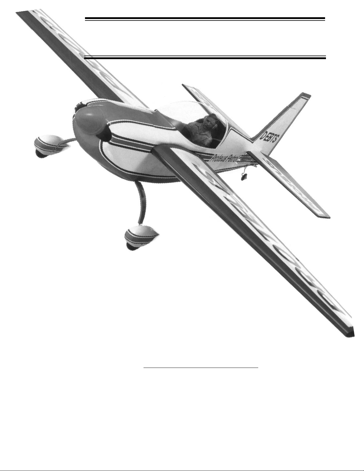
If there’s an aerobatic subject that can challenge the thrill of the Goldberg Ultimate, it’s this Extra 300! The Extra’s generous
moments, light wing loading and strong airframe make it an excellent airplane for the aerobatic pilot, whether he is learning
his first maneuvers or is an unlimited class competition flyer.Yet with all it’s aerobatic potential, this is still a very well-behaved
aircraft, making takeoffs and landings a breeze.And when it comes to engines
, please note: bigger is not better. A good .60
will do an excellent job. A larger than recommended engine may overly stress your model, causing structural failure.
WARNING
A radio-controlled model is not a toy. It is capable of causing serious bodily injury and property damage. It is the buyer’s
responsibility to build this kit correctly and to properly install the motor, radio, and all other equipment.The first test flights
should be made only with the assistance of an experienced R/C flyer. The model must always be operated and flown in
accordance with the safety standards of the Academy of Model Aeronautics.
Per the Federal Communications Commission, you are required to use only those radio frequencies specified “for Model
Aircraft.”
Pt. #2060 - 8/97
The Extra 300
© Copyright 1991
Page 2

2
ITEMS NEEDED TO COMPLETE THIS KIT
1 RADIO GUIDANCE SYSTEM (4 CHANNEL
MINIMUM REQUIRED)
1 ENGINE 2-CYCLE .60-90
4-CYCLE .90-1.20
PROPELLER (TO MATCH ENGINE SIZE)
1 3” DIAMETER SPINNER (LARGE ENOUGH
FOR PROP TO FIT WITHOUT MODIFICATION)
1 FUEL TANK TO MATCH ENGINE (12 OZ.
SHOWN ON PLAN)
1 24” SILICONE FUEL LINE
2 3” DIAMETER WHEELS
1 1-1/4” DIAMETER TAILWHEEL
1 2 OZ. BOTTLE MEDIUM CYANOACRYLATE
GLUE
1 CYANOACRYLATE ACCELERATOR
1 20-MINUTE EPOXY
1 LIGHTWEIGHT BALSA FILLER
1 1/2 x 8 x 12” FOAM PADDING
3 ROLLS OF COVERING
FUEL-PROOF PAINT FOR COWL AND
WHEELPANTS
OPTIONAL ITEMS
SCALE PILOT
PITTS STYLE MUFFLER
SMOKE SYSTEM
COMMERCIAL INCIDENCE GAUGE
NECESSARY TOOLS AND SUPPLIES
MISCELLANEOUS RUBBER BANDS
WAXED PAPER
MODELING KNIFE AND RAZOR BLADES
SANDPAPER (ASSORTED GRITS, INCLUDING
COARSE (80), MEDIUM (150) AND FINE (220-
320)
SANDING BLOCK
“T” PINS (at least 75)
BUILDING BOARD (24”x60”)
ELECTRIC DRILL
1/16” DRILL BIT
3/32” DRILL BIT
5/16” DRILL BIT
3/8” DRILL BIT
ALLEN WRENCH SET
SMALL SCREWDRIVER
MASKING TAPE
LONG NOSE PLIERS
COVERING IRON AND HEAT GUN
RAZOR SAW
SPRAY BOTTLE
SMALL SOLDERING IRON & SOLDER
10” 30°-60°-90° DRAFTING TRIANGLE
Page 3

3
USING THIS INSTRUCTION MANUAL
Before you start gluing and sanding, take some time
becoming familiar with the plans and looking through this entire
Instruction Booklet. It is designed to guide you through the
construction process step by step, so build in the order given in
this book. Balancing, setting up and flying the model are also
covered.
Like a full-size airplane, the Extra 300 is built from basic
structures (stabilizer, fin, wing, etc.), which are then assembled
into the complete airplane.
Special procedures or comments will usually be explained
before a step, so you will be prepared. If a step begins with a
statement like “Note,”‘Warning,”or “Important,” it is a good idea
to read through the step before doing it.
A check-off box appears at the beginning of each step .Check
these boxes as y ou b uild, so you can tell at a glance what steps
you have completed. Some steps are repeated and must be
marked twice, as in the case of the left and right wing panel.
Some of the instructions deal with general procedures.Boxes
are not needed for these sections.
HOW T O READ THE PLAN
There are two plan sheets in this kit, showing the Fuselage
(Body), the Wing, and the Tail Par ts. Everything on the plan is
drawn to full-size and shape and shows how the finished parts
fit together.
The plan is drawn to show the model completely assembled,
but as a result, the areas inside or underneath are covered up,
making it hard to understand how these parts fit together.
Therefore, for clarity, some par ts are drawn with hidden lines,
others with breakaway views, and some are entirely removed
from the structure and shown separately.
For example, on the fuselage, the left side of the completed
model has been removed to show the details inside.Sometimes
a surface is broken away to reveal the detail behind or
underneath.Dashed lines indicate details that are hidden behind
or under another part of the surface.
The model is made from four varieties of wood:balsa, bass,
birch, and various plywoods. Each kind of wood has its own
characteristic
end grain pattern
(as viewed from the end) which
has been drawn on the plan.Y ou can easily use these end grain
patterns to identify what kind of wood is shown for a part, if you
are in doubt.
HOW T O USE THE PLAN
The plan is used in several ways. The wings, stabilizer, and
fin are assembled directly over the plan. Each wood part is
matched over its corresponding location printed on the plan and
pinned in place. To prevent ruining your plan from gluing your
wings, etc. to it, cover the area you are working on with waxed
paper.
The paper the plan. is printed on can expand or contract
slightly with changes in temperature or humidity .Because of this,
a preformed part such as the notched wing trailing edge may not
exactly match the plan.This is no problem, as slight deviations
in the outline or size will not noticeably affect flight perf ormance.
Because the fuselage plugs together and is self-aligning, it is
not built directly over the plan. As you assemble the fuselage,
you will find the plan helpful in identifying parts and how things
fit together.
The plan also shows the installation of a typical radio, battery
and all remaining equipment and hardware needed to complete
the model. By referring to the examples shown, you should be
able to install your own radio, etc., even if it is not the same as
what is shown on the plan.
IDENTIFYING PARTS
Parts for the wing are bundled together;likewise, parts for the
tail assembly are also grouped. Die-cut plywood and balsa
sheets of common sizes are bundled together, so they are less
likely to be damaged during shipping and handling.
The various screws, hinges, and fittings are packaged in
plastic bags.
PREPARING FOR ASSEMBLY
Set a flat, warp-free pinning board on your work bench. Any
material that accepts pins, such as insulation board, soft
plywood, or dry-wall (sheet rock) will work.
Important:
any
warps or bends in the pinning board will result in wings or
tail surfaces that are also warped or bent, making your
model more difficult to fly.
Make sure that the pinning board
is flat by laying a straight edge across it. You may be able to
correct a warped board by shimming its low areas.
Position the area of the plan (such as the stabilizer) on which
you are going to build ov er the pinning board and tape it in place
so the plan lays flat and wrinkle free.
Place a sheet of waxed paper or plastic kitchen wrap ov er the
work area to prevent the C/A glue from sticking to y our plan and
ruining it.
CONSTRUCTION TIPS
In assembling your model, the follo wing tips will prove helpful.
IMPORTANT: ALWAYS READ A FEW STEPS AHEAD.This
will alert you to coming instructions and will help you plan
accordingly.
You may find it convenient to empty all of the small parts from
the hardware bags into a common container, such as a
margarine tub.This will help you find items quickly.
When drilling any 1/16” holes in balsa, you may find it easier
to twist the drill between your thumb and index finger. This
procedure allows more control in positioning the drill on the
center mark.
Punch out only the die-cut (D/C) parts you need as you
proceed. This will help you keep track of parts, especially the
small ones.
After completing each section of the aircraft, you may w ant to
go back and reglue the joints, just in case some area has been
missed. Be careful not to use too little glue, which will leave the
model weak or too much glue, which can make the model hea vy .
Properly glued joints are important to the overall strength of the
model. Medium C/A glue is recommended for most parts of the
assembly, although Jet Epoxy may be used when more time is
needed for careful placement.
INTRODUCTION
Page 4
4
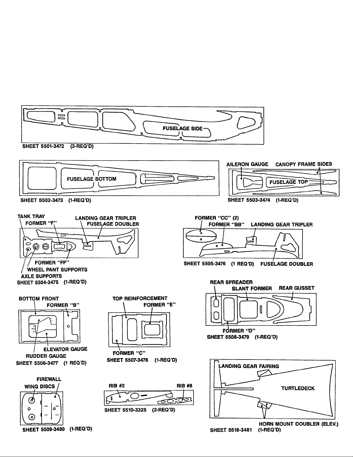
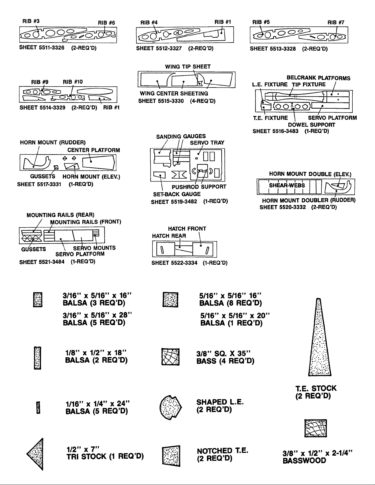
PARTS IDENTIFICATION
WOOD PARTS
Be careful Men removing parts (such as fuselage sides) from the
die-cut sheets.Long parts are fragile until glued into a structural
unit. If necessary, use a razor knife or razor saw to assist in the
removal of parts from the sheet.Sometimes a little trimming and
sanding can improve parts, Mere desired. Save scrap until the
model is completed, in case a part is missing or damaged. Also,
scrap is used in some building steps.
ABOUT THE WOOD IN THE KIT
We strive to supply good quality materials in your kit.Wood parts
are inspected with regard to the function they will serve. If an
imperfection is spotted in a scrap corner of a die-cut sheet and
doesn’t affect actual parts, the sheet is considered acceptable.
Also, internal stresses in wood are reliev ed as it is cut into parts.
These relieved stresses ma y cause some parts to bow. Bows in
wood parts (such as leading edges) readily straighten out as they
are glued into a structural unit
Page 5
5
Page 6
6
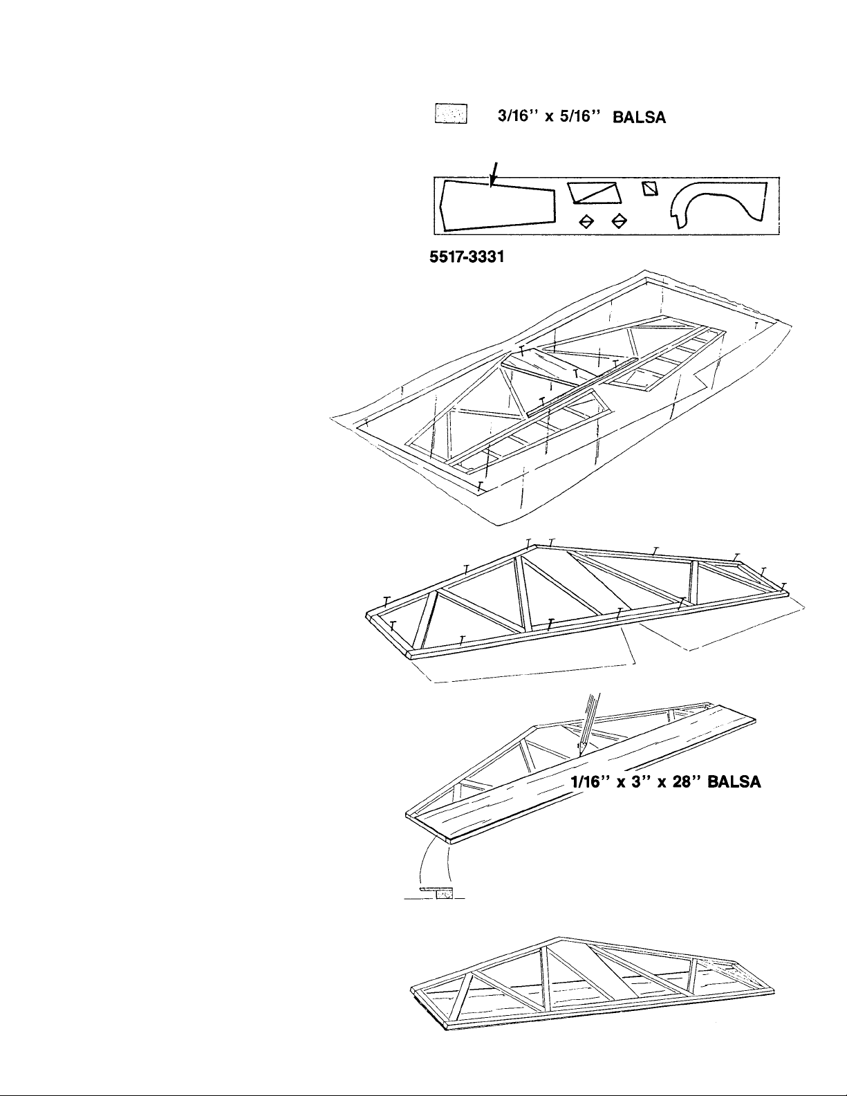
HORIZONTAL STABILIZER CONSTRUCTION (5 Steps)
1. Collect all of the items you will need to construct the
HORIZONTAL STABILIZER. They include:
(1) D/C SHEET 5517 3/16” BALSA PT. # 1331
Includes:
CENTER PLATFORM
(5) 3/16 x 5/16 X 28” BALSA STICKS PT. #4371
(4) 1/16 x 3 x 30” BALSA SHEETING PT.#4539
2. ■■ Lay the horizontal stabilizer portion of the plan over the
building board and place the waxed paper over the
plan.You will also need “T” pins, an X-Acto
®
knife with
a #11 blade, and a razor saw.
■■ Pin the CENTER PLATFORM over the plan.
■■ Cut a 3/16 x 5/16”balsa stic k and glue it to the platform
with medium CA, pinning it over the plan.
3. ■■ Trim the remaining 3/16 x 5/16” balsa sticks to fit the
plan, pinning and gluing as you go. In cutting the
diagonal trusses for the tail, trim them to fit well.If a bit
oversize, don’t force them in place. The pieces should
fit before gluing
4. ■■ Place a 1/16 x 3 x 28” balsa sheet flush to the trailing
edge (T.E.) of the stabilizer and mark the sheet width
onto the stab sticks.
HINT: In selecting the sheeting for the stab , choose the firmer
or heavier wood. whenever sheeting any surface, is
helpful to lightly sand both sides of the sheet before
using medium C/A. Also, whenever joining sheeting,
“truing”the edges to be glued with a long sanding b lock
and prefitting can make a big difference.
■■ Remove the sheet and apply medium C/A to the stab
sticks up to the sheet-width mark
■■ Place the glued stab frame over the 1/16” sheeting,
making sure that the trailing edge is flush with the
sheet.
Page 7
7
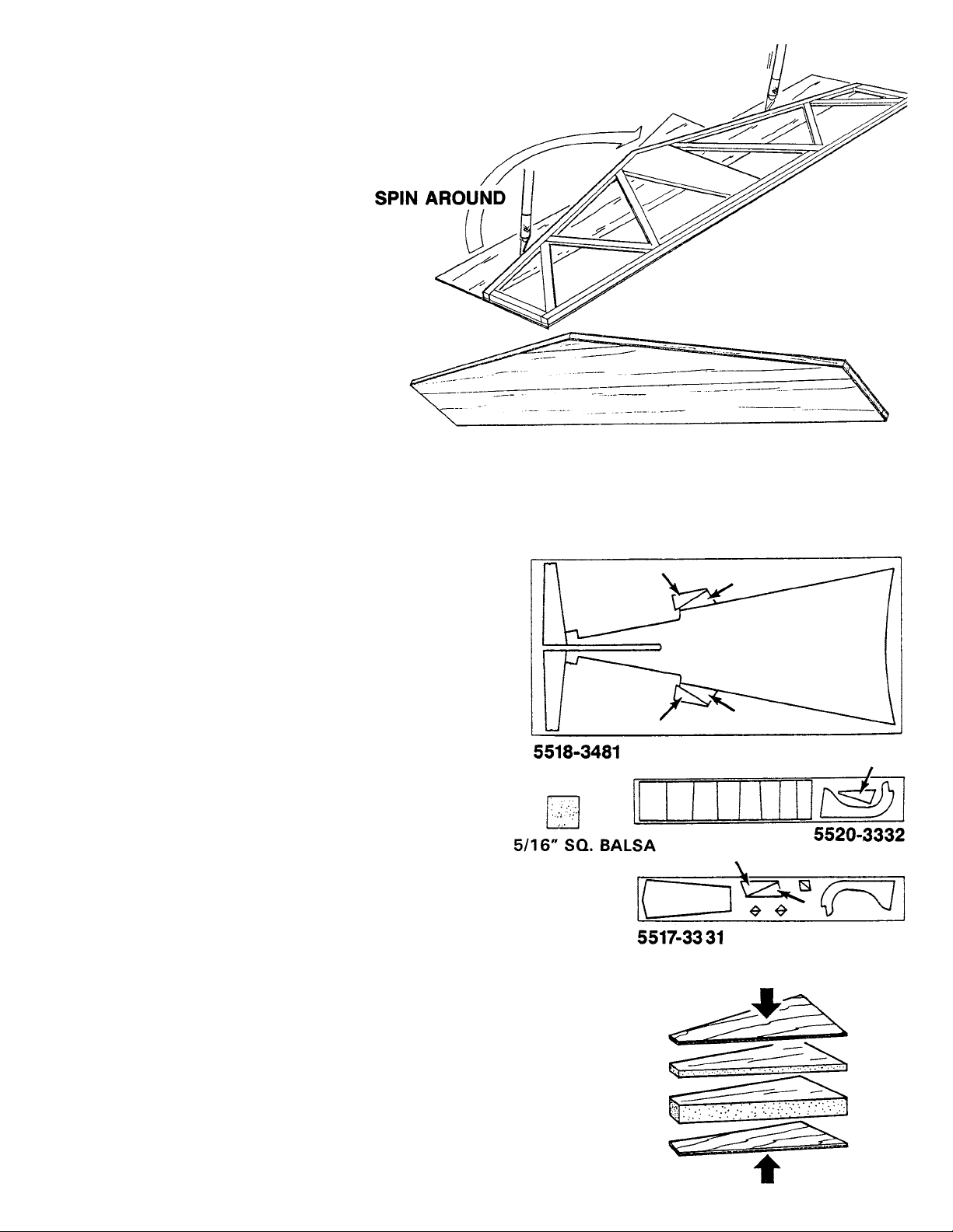
5. ■■ Glue the remainder of the stab frame and install
another 1/16” balsa sheet. Then, tr im the sheeting to
the profile of the stab.
■■ Spin the cut-off around and glue to the remaining space
on the frame.
■■ Flip the stab over and sheet it as shown above.
ELEVATOR CONSTRUCTION (4 Steps)
1. ■■ Collect all of the parts needed to build the two
ELEVATOR HALVES.They include:
(5) 5/16” sq.x 16”BALSA STICKS PT. #4370
(1) BIRCH PLY D/C SHT. 5518 CONTAINING:
(4) HORN MOUNTS PT. #3481
(1) D/C BALSA SHT. 5520 CONTAINING:
(2) HORN MOUNT CORES PT. #3332
(2) D/C SHT. 5517 (BALSA) CONTAINING:
(1) BALSA CORNER GUSSETS PT. #3331
(1) BALSA HORN MOUNT CORES PT. #3331
2. ■■ Laminate the two 1/32”PL YWOOD HORN MOUNTS to
the 3/16” and 1/16” BALSA CORES.
■■ Make two such assemblies, one for each elevator half.
THIS COMPLETES THE HORIZONTAL STABILIZER. PUT IT
ASIDE FOR NOW;YOU WILL NOT NEED IT UNTIL YOU ARE
READ Y T O INST ALL THE HINGES.
Page 8
8
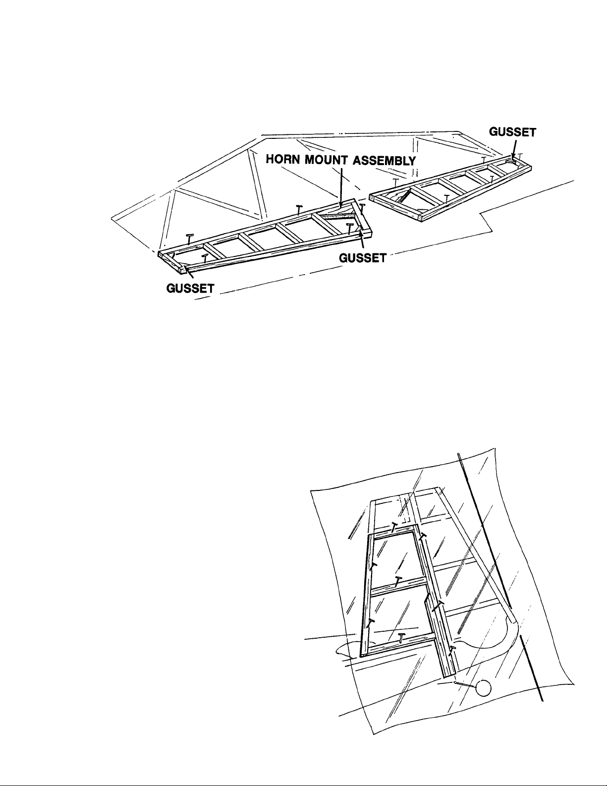
3. ■■ Place waxed paper over the elevator section of the
plan.
■■ Trim and glue the 5/16” square balsa sticks over the
plan, pinning as you go.
4. ■■ Glue the HORN MOUNT ASSEMBLIES and the
CORNER GUSSETS into the frame.
1. ■■ Collect the items needed to construct the VERTICAL
FIN.They include:
(3) 3/16 x 5/16 x16” BALSA STICKS PT. #4369
(2) 1/16 x 3 x 18” BALSA SHEETS PT. #4538
2. ■■ Cover the fin portion of the plan with waxed paper.
■■ T rim the 3/16 x 5/16”balsa sticks and pin over the plan,
gluing as you go.
VERTICAL FIN CONSTRUCTION (4 Steps)
Page 9
9
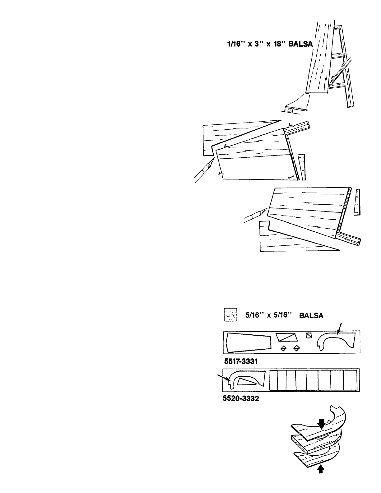
3. ■■ Place the 1/16” balsa sheeting flush with the Leading
Edge (L.E.) and mark the width of the sheet onto the
frame.
■■ Apply Jet to the frame, up to the width marks, and
permanently install the sheeting. Pin down to insure a
flat assembly.
■■ Trim the sheeting and use the drop-off to cover the
remaining area of the fin side, trimming to the profile of
the fin as you go.
4. ■■ Flip the fin over and repeat the sheeting operation, as
illustrated.
THIS COMPLETES THE VERTICAL FIN CONSTRUCTION.
PUT IT ASIDE UNTIL YOU ARE READY TO INSTALL THE
HINGES.
1. ■■ Collect all of the parts you will need to construct the
RUDDER.They include:
(3) 5/16” sq. x 16”BALSA STICKS PT. #4370
(1) D/C BALSA SHT. 5517 PT. #3331
CONTAINING:
(1) 3/16” HORN MOUNT
(2) D/C BALSA SHT. 5520 PT. #3332
CONTAINING:
(1) 1/16” HORN MOUNT
2. ■■ Laminate the three horn mounts as shown, making
sure that the 3/16” horn mount is in the middle.
RUDDER CONSTRUCTION (4 Steps)
Page 10
10
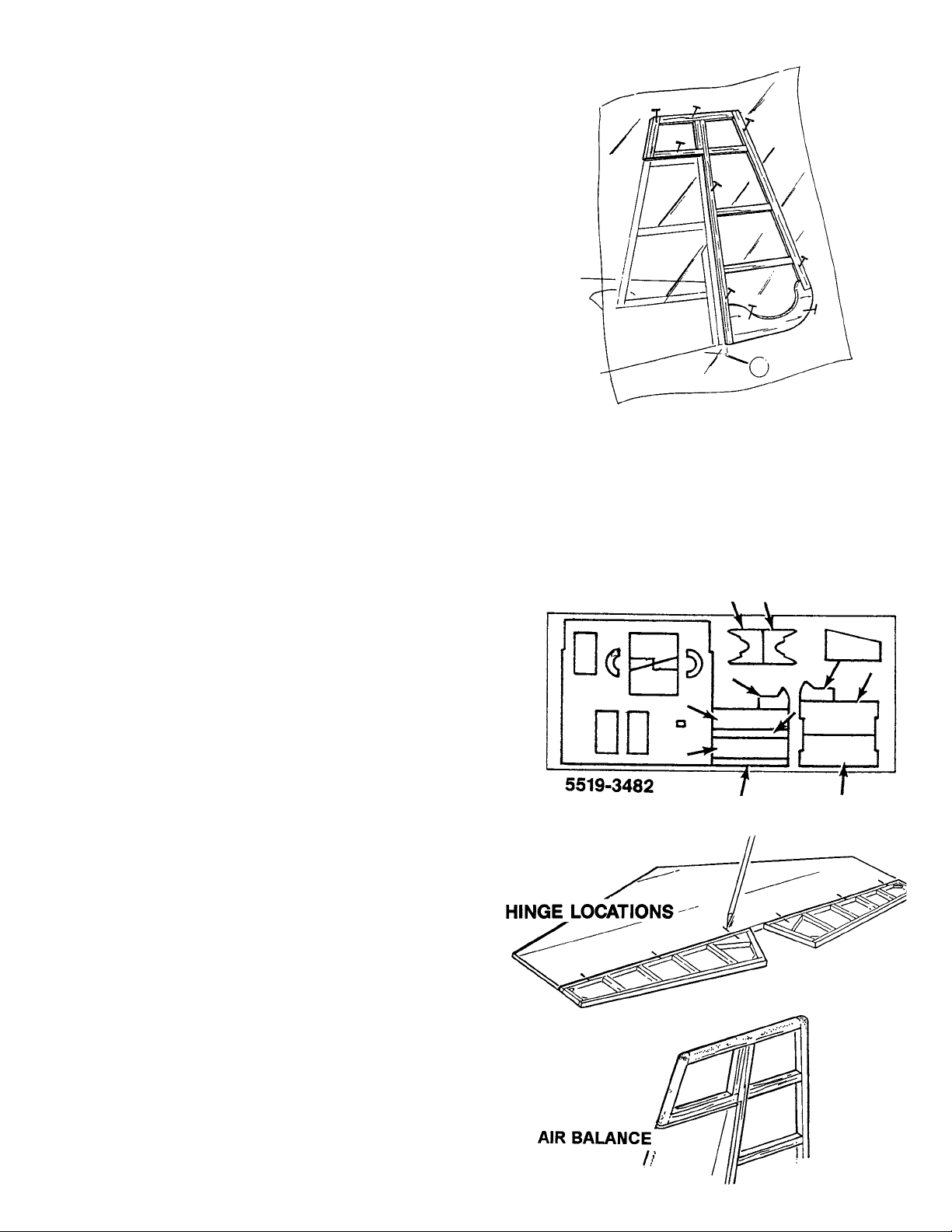
3. ■■ Cover the RUDDER por tion of your plan with waxed
paper and pin the laminated horn mount assembly over
the plan.
4. ■■ Trim, glue, and pin the 5/16” square balsa sticks over
the plan as shown.
NOW GATHER THE HORIZONTAL STABILIZER, THE
ELEVATOR HALVES, THE FIN AND THE RUDDER AND
PROCEED TO THE NEXT SECTION, “ROUNDING AND
HINGING.”
ROUNDING & HINGING (11 Steps)
1. ■■ Collect all of the items needed to complete this section.
In addition to the following kits parts, you wiII need a
small drill, drill bits, a modeling knife, a sharp pencil, a
sanding block, and fine and medium grit sandpaper.
(9) JET HINGES PT. #1667
(1) D/C PLY SHT. #5519 PT. #3482
CONTAINING:
(1) ROUNDING TOOL
(1) “R”BEVEL TOOL
(1) “AE”BEVEL TOOL
(1) CG NYLON CENTERLINE MARKER PT. #1425
2. ■■ From the plan, transfer the hinge locations onto the
rudder and the elevator halves.
■■ Next, transfer the hinge locations from the rudder to the
fin, and from the elevators to the stab.
NOTE: Leave a 1/16” gap between the air balance on both the
rudder and the fin.
Page 11

11
3. ■■ Using the centerline tool, scribe the centerline onto the
rudder post, the fin post, the hinge line of the stabilizer,
and onto both elevators
4. ■■
Carefuly cut a slot approximately 1/2” deep and slightly
wider than the hinge, using your favorite knife blade.
5. ■■
After all slots have been made, mark the center of your
hinge and insert a pin (see illus.) This will hold the
hinge in place while sliding the matching part (aileron,
etc.) onto the JET HINGE.
DO NOT GLUE!
■■
With both surfaces hinged and assembled, check the
alignment. For good control response, the hinge gap
should be as small as possible, but should
allow for full deflection when needed.
Remove the hinges.
6. ■■ Assemble the two bevel tools and install a str ip of
medium grit sandpaper, as shown.
7. ■■ Using the tool marked “R,” bev el the rudder-side of the
hingeline to a point at the centerline.You may want to
bevel near the air balance with a knif e , if you can’t use
the tool in the corner.
■■ Using the tool marked “AE,” bevel the elevators to a
point at the centerline.
8. ■■ T emporarily hinge the rudder/fin and the stab/elev ators
to check the surface alignment and to round the
perimeter of the assemblies.
Page 12
12
9. ■■ Assemble the Rounding Tool and install a piece of
medium sandpaper.
10. ■■ Using the tool, round the perimeter of the fin/rudder and
the stab/elevators.
■■ When you are satisfied with the shape, use a piece of
fine sandpaper to remove the deep scratches.
11. ■■ Finish sand all of the tail par ts, using a sanding block
and fine sandpaper.
HINT: Sanding will cause gaps at the joints to fill with balsa
dust. Use this to your advantage by putting a drop of
thin C/A glue into the gap. Then sand after the glue
dries.
■■ Separate the fin from the rudder and the elevators from
the stabilizer.
THIS COMPLETES THE CONSTRUCTION OF THE TAIL
SECTION PARTS.PUT THEM ASIDE UNTIL YOU ARE READ Y
TO A TTACH THEM T O THE FUSELAGE.
Page 13
13
THE INSTRUCTIONS WILL LEAD YOU THROUGH THE
ASSEMBLY SEQUENCE, OCCASIONALLY SENDING YOU
BACK TO REPEAT STEPS. CAREFULLY READ EACH STEP
BEFORE YOU PROCEED TO DO THE INSTRUCTION.
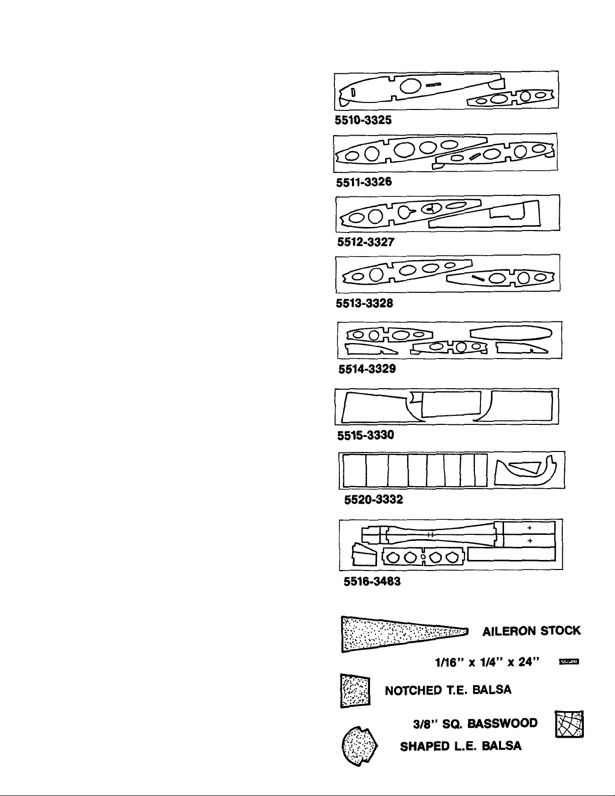
1. Find all the parts that you will need to build the wing.
THEY INCLUDE:
(4) 3/8" SQ. X 35" SPAR BASS (MIL #4528)
(2) SHAPED L.E BALSA (MIL #4524)
(2) NOTCHED T.E BALSA (MIL #4523)
(2) WING RIBS 2 & 8 BALSA (D.C. 5310-3325)
(2) WING RIBS 3 & 6 BALSA (D.C. 5511-3326)
(2) WING RIBS 4 & 1 BALSA (D.C. 5512-3327)
(2) WING RIBS 5 & 7 BALSA (D.C. 5513-3328)
(2) WING RIBS 1, 9 & 10 BALSA (D.C. 5514-3329)
(4) WING CENTER SHEETING BALSA
(D.C. 5515-3330)
(2) SHEAR-WEBS BALSA (D.C.5520-3332)
(2) WING JOINER PLY
(2) BELCRANK PLATFORMS PLY
(D.C. 5516-3483)
(2) DOWEL SUPPORT PLY (D.C. 5516-3483)
(1) WING SUPPORT FRT PLY (D.C. 5516-3483)
(1) WING SUPPORT REAR PLY (D.C. 5516-3483)
(1) WING SUPPORT TIP PLY (D.C. 5516-3483)
(1) SERVO PLATFORM PLY (D.C. 5516-3483)
(1) DOWEL GUIDE PLY (D.C. 5509-3480)
(2) INBOARD T.E. BALSA (MIL #4526)
(5) 1/16" x 1/4" x 24" CAPS BALSA (STK #4525)
(2) AILERONS BALSA (MIL #4527)
(6) 1/16" x 2-3/4" x 35" BALSA (SHT #4888)
(4) 1/16" x 2-1/2" x 35" BALSA (SHT#4887)
(1) 3/4" x 33" NYLON FABRIC (NYL #5210)
(1) 5/16" x 4-3/4" DOWEL BIRCH (MIL #1759)
(2) .063" x 20-3/4" AILERON WIRE (MTL #1230)
(2) .063" x 7" THREADED ROD (MTL #1270)
(2) AILERON BELCRANKS (NYL #1410)
(2) AILERON BUSHINGS (MTL #1182)
(2) 2-56 NUT (MTL #1115)
(2) 2-56 x 1/2" MACHINE SCREW (MTL #1041)
(2) #2 WASHER (NYL#1461)
(4) NYLON SNAP-NUT (NYL #1138)
(3) 1/16" I.D.x 1" BRASS TUBE (BRS #1376)
(1) AILERON COUPLER BLOCK (NYL #1427)
(1) 2-56 x 3/4" MACHINE SCREW (MTL #1042)
(1) 2-56 x 1/8" MACHINE SCREW (MIL #1040)
(1) SNAP LINK (NYL #1405)
(8) FLEX POINT HINGES (NYL #1449)
(1) C.G.CENTERLINE TOOL (NYL #1425)
CONSTRUCTING THE WING (35 Steps)
Page 14
14
NOTE:IF USING AN ENGINE LARGER THAN A.60 2-CYCLE,
YOU WILL WANT TO FOLLOW THE INSTRUCTIONS FOR THE
TWO SERVO OPTION, WHICH ARE FOUND IMMEDIATELY
AFTER THE WING SECTION.
NOTE:Y OU WILL BE BUILDING TWO WING HAL VES.DO NOT
BUILD BOTH HALVES OVER THE SAME SECTION OF THE
PLAN. FOLLOW STEPS CAREFULLY TO AVOID
CONFUSION
2. ■■ Cut the vying plan along the dotted line.Position the left
wing plan overlapping the right plan, aligning the
arrows as shown. Pin or tape the plan to the building
board and cover with waxed paper,
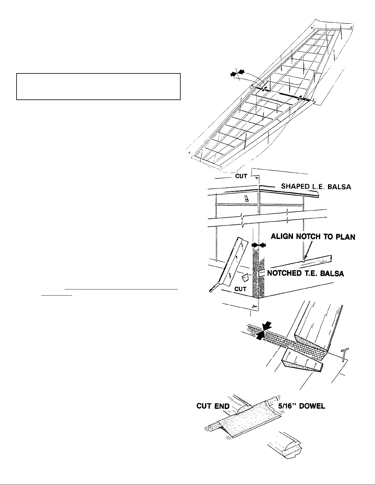
3. ■■ Lay a shaped LEADING EDGE over the plan and cut
the angle at the centerline. Repeat this step on the
other L.E.
■■ Next, place the notched TRAILING EDGE over the over
the plan, aligning the notches to insure that y
ou cut the
correct end. Cut the angle at the centerline and then
repeat this step on the other notched T.E.
■■ Referring to the plan, cut the inboard T. E. parts to the
correct length and angle.
4. ■■ Wrap a piece of fine sandpaper around the 5/16”
DOWEL and sand the wing pin notch into the angle-cut
end of the shaped L.E.
Page 15

15
5. ■■ Scissors-pin a 3/8” sq. BASSWOOD SPAR over the
plan, as shown. Make sure that the end is on the plan
centerline.
6. ■■ Pin tabbed Rib #2, #6, and #10 over the plan, but DO
NOT GLUE at this time.
7. ■■ Place the notched T.E.on the support tabs, with the cut
end at the centerline. Press the ribs into the notches
and glue.
■■ Remove the other ribs from their sheets.
IMPORTANT: Save the “horseshoe”- shaped punch out in
Rib #4, as you will need it for Step #29.
■■ Place the remaining ribs into the notched T.E.and onto
the spar, but DO NOT GLUE. Make sure that you
correctly install Rib #7, as shown.Match the bellcrank
support slot direction to Rib #6.
Page 16

16
8. ■■ Position the shaped L.E. onto the support tabs. Make
sure that the beveled/notched end is in line with the
wing centerline. Use a drafting triangle to project the
wing centerline to the L.E. end.
■■ Using the set-back gauge for correct positioning, gently
slide the top spar into the rib notches.
■■ Check the wing alignment with the plan underneath.
Then, place a drop of Jet glue at each joint along the
Leading Edge, the Spar, and the Trailing Edge.
9. ■■ Glue the balsa shear webs to the
front side of the spars, centering the
shear webs between the wing ribs.
NOTE: IF YOU ARE USING THE TWO-AILERON SERVO
SYSTEM, OMIT THE FOLLOWiNG.
■■ Drill a 1/16” diameter hole at the center mark on each
of the aileron bellcrank supports and glue the suppor t
between Ribs #6 and #7.
10. ■■ Edge glue two sets of three 1/16 x 3 x 36”balsa sheets.
■■ Measure 3-5/16” from opposite edges, as shown, and
mark.
■■ Cut along the line established by the two marks.Repeat
this process on the other glued sheet. This gives you
the L.E. sheeting for the entire wing.
Page 17

17
11. ■■ Position a full sheet edge against the L.E. shoulder.
Align the corner with the L.E. centerline end and roll
onto spar.
■■ Mark the sheet in line with the top spar end and cut
along the line formed. Use this sheet as a template to
cut the other three L. E.sheets.
12. ■■ Glue the L.E. sheeting to the L.E. shoulder, ribs, and
spar, pinning or taping to secure until dry.
■■ Glue the 1/16 x 2-1/2 x 36” Trailing Edge sheeting to
the notched T.E.and the wing ribs.
13. ■■ To glue the center sheet in place, first install the front
and back pieces.Then, slide the center piece in tightly.
Trimming may be necessary.
■■ Place some glue on the wing tip sheeting and slide in
place.
■■ Cut the 1/16 x 1/4”balsa capstrips to fit and glue to the
wing ribs.
14. ■■ Trim the sheeting along the wing centerline.
Page 18

18
15. ■■ Glue the pretrimmed Trailing Edge par t to the wing.
Align the “angle-cut” side with the notched T.E. Make
sure the top of the T.E.and the wing sheeting are flush
over the entire length.
REMOVE THE WING PANEL AND GO BACK TO STEP #3.
MAKING SURE
TO WORK OVER THE OTHER HALF OF THE
WING PLAN. REPEAT THE CONSTRUCTION SEQUENCE
FOR THE OTHER WING PANEL.
AFTER COMPLETING STEP #15 FOR THE SECOND TIME,
GO ON TO THE NEXT STEP.
16. ■■ Glue the front, rear, and tip wing fixture supports, as
shown.
17. ■■ Locate the wing fixtures and pin to the plan. Align the
marks on the tip fixtures to the spar on the plan.
18. ■■ Laminate the top and bottom portions of Rib #1.
Page 19

19
19. ■■ Pin the right wing panel to the building board, directly
above the wing plan outline.
■■ With the cut-outs pointing down assemble the dowel
support to one of the Rib #1 front sections, BUT DO
NOT GLUE.
■■ With the dowel support assembly inserted into the fixed
right wing panel, slide the left wing half into position.
Sand and trim to fit, as needed.When satisfied with the
fit, pin the left wing to the board, directly above the plan.
20. ■■ Lightly sand joiners and spars for maximum bond.
Then, apply 20 MINUTE EPOXYto the wing joiners and
insert into the wing around the spars.
■■ Clamp to form a gap-free joint. Check to see that the
wing is firmly on the fixtures while the joiners are drying.
21. ■■ Laminate the rear portion of Rib #1.
NOTE: IF YOU ARE PLANNING T O USE THE TWO-AILERON
SERVO SYSTEM, DO NOT PUNCH OUT THE
CENTER-MOUNTED SERVO BLANK, AS SHOWN
HERE. GLUE IT IN PERMANENTLY.
■■ Install the rear portion of Rib #1 directly over the
centerline and glue.Trim to fit, if needed.
NOTE: OMIT THE FOLLOWING STEP, IF BUILDING THE
TWO-SERVO OPTION.
■■ Install and glue the servo mount into the slots in Ribs
#2 and onto Rib #1.
Page 20

20
22. ■■ Drill a 5/16” diameter hole at the center mark of both
discs.Then, slide the dowel through the Leading Edge,
the support, and the dowel guide.
■■ Insert the remaining front por tion of Rib #1 onto the
dowel.Generously EPOXY the entire front rib area, as
well as the dowel support tabs in Rib #2.
23. ■■ Crack off all of the support tabs.
■■ Glue the remaining pretrimmed L.E. sheeting to the
wing. Pin or tape to secure until dry.
■■ Fit and trim the T.E.sheeting and glue to the wing
NOTE: IF YOU ARE USING THE TWO-SERVO
OPTION, GO ON TO STEP 31.
24. ■■ Bend a 5/16” x 900 angle at one end of the .063
diameter x 20-3/4” wire pushrod.
■■ Install an aileron bellcrank onto the bend.(See plan for
correct orientation.) Secure with a snapnut. Place a
drop of JET glue on the snap-nut.
Page 21

21
■■ Slide the pushrod assembly through the openings in
the wing ribs from Rib #6 toward the center.
■■ Install the hardware to mount the bellcrank to the
platform.
25. ■■ Using the plan for reference, cut the aileron pushrod
exit holes in the T.E.sheeting.
26. ■■ Make to pushrods to fit the template shown here.
27. ■■ Install the threaded pushrods onto the bellcranks and
secure with a snap-nut.Place a drop of JET glue onto
the snap nuts.
■■ Referring to the plan, fix the bellcranks in the neutral
position with a “T”pin.
28. ■■ Assemble the aileron coupler.
Page 22

22
29. ■■ Slide one 1/16” ID.x 1”brass tube onto the left aileron
pushrod and one tube onto the right aileron pushrod.
■■ Slide the aileron coupler assembly onto both pushrods.
The coupler block should be centered on the wing
centerline.
■■ Check that the bellcranks are still “fixed”in the neutral
position and solder the coupler tube to each pushrod.
The other brass tubes will be positioned after the servo
is mounted.
30. ■■ Connect the aileron ser vo to the pushrod. Locate the
servo so that the bellcranks are in the neural position.
Tighten the setscrew and mount the servo.
■■ In each wing half, center the brass tubes on the aileron
pushrods at Rib #4.
■■ Glue the “horseshoe”-shaped balsa piece (retained
from Step #7) to Rib. 4, laterally locking the brass
bushing in the wing.
Page 23

23
31. ■■ Cut out the opening for the aileron servo as you install
the center sheeting.
NOTE: IF Y OU ARE USING THE TW O-SER V O OPTION,CUT
A SMALLER OPENING FOR SERV O LEAD ACCESS
ONLY.
■■ Glue the tip sheeting in place and install the capstrips.
■■ Remove the wing assembly from the building board.
32. ■■ Sand flat the end ribs and glue the balsa tip rib to both
tips.
■■ Sand the perimeter to match the airfoil.
33. ■■ Sand the wing, blending all the seams and joints. Use
a tack rag to remove all of the dust when finished.
34. ■■ Star ting at the front of the servo cut-out, completely
wrap the center of the wings with 3/4”nylon tape.Smear
glue through the fabric weave, using a plastic bag to
protect your finger.
■■ Trim the excess at the rear servo cut-out.
Page 24

24
35. ■■ At this time, transfer hinge locations from the plan to
the ailerons.Next, transfer these marks to the wing.Be
sure to leave a 1/16”gap between the aileron and the
T.E. center section.
■■ Use a CGM centerline tool and scribe a hinge
centerline into both ailerons and wing halves.
■■ Hinge the ailerons just like you did the elevator and
rudder
■■ Bevel the ailerons to the center scribe line, using the
bevel tool marked “AE.”
■■ Temporarily hinge the ailerons to the wing to test the
fit.Then, sand the aileron to the tip plane of the wing.
NOTE: Permanent assembly of the ailerons to the wings,
as well as control horn installation, is done after
covering.
IF YOU ARE INSTALLING ONLY ONE SERVO, THE WING
CONSTRUCTION IS NOW COMPLETE.
NOTE: The two-servo option should be used for aircraft
using an engine larger than a .60 2-cycle.
1. ■■ Collect the following parts needed to install an aileron
servo in each wing panel.
(1) D/C SHT. #5521 PLY PT. #3484
CONTAINING SERVO MOUNTING PARTS
(1) D/C SHT. #5522 BALSA PT.#3334
CONTAINING HATCH COVERS
(16) #2 x 5/16” SHT.METAL SCREW PT. #1086
(16) #2 WASHER PT. #1138
TWO-SERVO SYSTEM CONSTRUCTION (6 Steps)
TO BE INSTALLED ON A COMPLETED WING
Page 25

25
2. ■■ Laminate the two ply front platform supports and glue
to the spar, centering between Ribs #6 and #7.
■■ Glue the rear platform support to Ribs #6 and #7 and
to the T.E.sheeting.
3. ■■ Drill a 1/16”diameter hole in each corner of the platform
and mount to the rails, using four of the #2 x 5/16”
screws and washers.
4. ■■ Glue the corner gussets to the servo mounts and fasten
the assemblies to a servo.
5. ■■ Glue a corner gusset to each corner of the ser vo bay,
as shown.
■■ Fabricate the balsa hatch and drill a 1/16”diameter hole
in each corner.
■■ Center the servo arm in the slotted hole of the hatch
cover to locate the servo. Remove the hatch and glue
the servo gussets and mounts to the platform.
6. ■■ After the wing is covered, and with both the servo and
aileron in the neutral position, measure and connect the
pushrod.
THIS COMPLETES THE WING.NOW LET’S MOVE ON TO THE
FUSELAGE.
Page 26

26
1. ■■ Gather all of the parts needed to construct the
FUSELAGE.They include:
(2) D/C SHT. 5501 PLY SIDES PT. #3475
(1) D/C SHT. 5502 PLY FUSE BOTTOM PT. #3473
(1) D/C SHT. 5503 PLY PT. #3474
CONTAINING TOP & BACKUPS
(1) D/C SHT. 5504 PLY PT. #3475
CONTAINING DOUBLER, TRIPLER, FORMERS &
FUEL T ANK TRAY
(1) D/C SHT. 5505 PLY PT. #3476
CONTAINING DOUBLER, TRIPLER & FRMRS
(1) D/C SHT. 5506 PLY FRMRS & GAUGES PT. #3477
(1) D/C SHT. 5507 PLY FORMERS PT. #3478
(1) D/C SHT. 5508 PLY FORMERS PT. #3479
(1) D/C SHT. 5509 PLY FIREWALL PT. #3480
(1) D/C SHT. 5518 PLY TURTLEDECK PT. #3481
(1) 1/32” PLY FRONT/TOP SHEET PT. #4602
(1) BASS WING MOUNTING BLOCK PT. #4372
(1) 1/4” PLY LANDING GEAR BLOCK PT. #4373
(2) BASS MOTOR SPACER PT. #4374
(1) 1/2” x 7” BALSA GUSSET PT. #4217
(2) 1/8 x 1/2 x 18” BALSA STICK PT. #4376
(6) 6-32 BLIND NUT PT. #1124
(6) 6-32 x 1-1/4” SOCKET HD. SCREW PT. #1024
(2) #6x3/4”WASHER PT. #1144
(4) #6 x 3/4” SHT. METAL SCREW PT. #1082
(2) MAIN LANDING GEAR WIRE PT.#1322
(2) MOTOR MOUNT PT.#1466
2. ■■ Carefully remove the parts from the die sheets and
lightly sand the rough edges of each part.
3. ■■ With the scribe lines exposed, glue FIREWALL
FORMER “AF”to the other fire w all half. Make sure the
top and side edges match. Note the bottom offset fit.
Tape together and allow the assembly to dry on a flat
surface.
■■ Drill a 3/8” diameter hole at the center mark.
CONSTRUCTING THE FUSELAGE (36 Steps)
Page 27

27
4. ■■ Position the ‘DRIVE W ASHER,”of y our engine over the
drive washer on the plan.
■■ Place the MOT OR MOUNT against the firewall over the
plan.Y ou may require spacers to accomplish the proper
position.
■■ Tack glue the engine to the mounts.
NOTE: MAKE SURE THAT THIS DIMENSION IS AT LEAST
1/4”.If not, use basswood spacers between the firewall
and the motor mounts.
5. ■■ Place the motor assembly over the “AF” side of the
firewall.
■■ Measure 1/2 of the total distance between the mounts,
from the scribe mark on the firewall to one of the
mounts.
■■ With the holes on the vertical scribe marks on the
firewall, mark all four mounting bracket locations.
■■ Drill a 5/32” hole at each location.
■■ T urn the firewall ov er and insert the four 6-32 blind nuts.
Seat them with a soft hammer blow.
■■ Coat the edges of the nut with JET GLUE. Be careful
to not get glue in the threads. Put the assembly aside
for now.
6. ■■ Locate, glue, and trim the 1/8 X 1/2” balsa doublers to
the four formers, “D,” “E,” “F” and the SLANT former.
Page 28

28
7. ■■ Glue the wing-saddle doublers to the inside of the
fuselage sides.Reference the landing gear block area
and the wing curve for the correct alignment.
8. ■■ Glue the landing gear triplers onto the wing saddle
doublers.Make sure that the landing gear wire slots are
in line.
9. ■■ With the triplers face to face, tape the fuselage sides
together at the rudderpost end. Use a scrap piece of
3116” balsa spacer between the sides.
■■ Install Former “D” (balsa doubler forward) and secure
with a rubber band.
■■ Install Formers “E” and “F,” using rubber bands to
secure at each former.
10. ■■ Slide the fuselage top under the rubber bands and
press into position. Loosen the tape at the rudderpost
end to allow top to fit.
Page 29

29
11. ■■ Slide in the “SLANT” former.
12. ■■ Flip the fuselage over and install the bottom sheet.
■■ Position the fuselage over the TOP VIEW of the plan
and check the alignment.Use small pieces of masking
tape to secure the structure as you go.
■■ Sight-check down the fuselage to insure against twist.
13. ■■ When the fuselage is perfectly aligned, glue all of the
seams created by the sides, top, bottom and formers.
Page 30

30
14. ■■ Glue the landing gear block to the fuselage assembly.
Make sure the groove is facing out.
■■ Glue Former “C” to the landing gear block and the
triplers.
15. ■■ Glue in Former “B.” Check that the former is flush with
the fuse side slot.
16. ■■ Glue the FIREWALL onto the fuselage assembly .Make
sure that the blind nut flanges are on the inside.
17. ■■ Glue the bottom-front piece in place.
Page 31

31
18. ■■ Use the wing to locate the doubler disc. Correctly
position the disc to Former “B”and epoxy in place.
19. ■■ T o the wing mounting bloc k, insert a 6-32 blind nut into
each hole on the surface Mere the holes are centered.
Make sure that the nut spurs are full set into the wood.
Tap with a hammer to insure a good fit.
20. ■■ With the blind nuts on the under side, test fit (and trim,
if necessary,) the b lock assembly into the cutouts in the
doublers.When you have a proper fit, Epoxy in place.
21. ■■ Install the gusset into the slot in the slant former and
down into the notches in the doublers. The gusset
should also rest on the wing mounting block.When you
are satisfied with the fit, glue in place.
22. For the next few steps, you will need the wing.
■■ Place the fuselage on a stable, flat surface. Insert the
wing pin dowel into the hole in Former “B.” Slide the
wing as far forward as it will go.
■■ True the wing to the fuselage by adjusting the distance
from the wing-tip to the tail until both sides are equal.
When you are satisfied, secure the wing to the fuselage
with tape.
Page 32

32
23. ■■ Flip the wing/fuse over and drill a small pilot hole (no
larger than 7/64”) through the wing.
■■ Remove the wing from the fuse and drill a 5/32” hole,
using the pilot hole as a guide.
■■ Test bolt the wing to the fuselage and check to make
sure the tip-to-tail dimensions are still equal.
24. ■■ Trim and glue the 1/2” balsa triangle stock behind the
firewall.
25. ■■ Glue in the top reinforcement.
26. ■■ Glue in the remaining triangle stock, as shown.
Page 33

33
27. ■■ Locate Former “BB” at a 900 angle to the front
reinforcement and glue.
28. ■■ Glue one edge of the 1/32” ply TOP SHEET to the fuse.
Then, using a spray bottle to soak the sheet, slowly roll
to the opposite side, gluing as you go.
NOTE: MARK THE CENTERLINE ON THE TOP SHEET AND
THE FUSE TO INSURE A CORRECT FIT.
■■ Sand the edges in line with the firewall and Former “BB . ”
29. ■■ Install Former “FF directly above Form “F”and at a 900
angle to the fuse top.
30. ■■ Mark the center line onto the horizontal stabilizer and
on the stab platform of the fuselage.
■■ Glue the stabilizer to the platform, locating it on the
centerlines and against Former “FF.” Check the
stabilizer to insure that it is parallel to the base.
Page 34

34
31. ■■ Install the vertical fin. Inser t the rudderpost into the
rudderpost slot. Tilt the fin forward until it rests on the
top surface of the stab.
■■ Check that the assembly is square, using a 900
triangle.
■■ Permanently glue the fin to the stabilizer and fuselage.
32. ■■ Glue the ply “BACKUP”pieces to the stab on each side
of the fin.
33. ■■ Slide the 1/32” ply turtledeck around the fin.
■■ With a water spray bottle, liberally soak the top
centerline of the turtledeck.This will allo w the plywood
to be formed without splitting.
■■ Wrap the ply around the formers and down onto the
fuselage sides.Sand the sides for a smooth fit.
34. ■■ When satisfied with the fit, apply glue to the formers,
fuselage sides, fin and stab.
■■ Quickly wrap the plywood down to the fuselage and
tape in place until dry.
35. ■■ Bevel the plywood edge at the fuselage lap-joint and
sand the edge flush with the slant former.Fill the step
with CGM Model Magic filler.
■■ Apply additional filler to the fin and stabilizer seams and
blend to create a smooth transition.
36. ■■ Go over the fuselage, sanding all seams and joints with
medium sandpaper. Then, sand the entire fuselage
with fine grit sandpaper.The effor t you put into finish
sanding will show, as no covering material will hide a
poor sanding job!
■■ Now go back to all of the built-up parts to inspect the
sturdiness of joints and to finish sand. When satisfied
with the finish, the aircraft is ready for covering.
Page 35

35
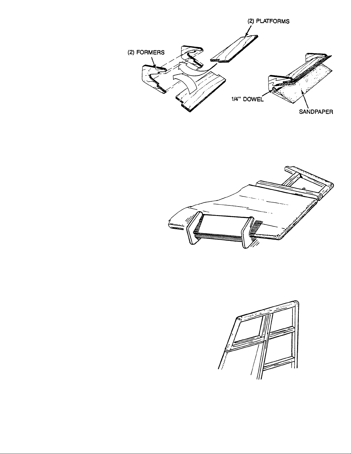
1. ■■ Collect the parts needed to construct the LANDING
GEAR FAIRINGS. They include:
(2) LANDING GEAR 3/16”WIRE PT.#1322
(2) LANDING GEAR STRAP PT. #1418
(4) #2 x 3/8” SHT. METAL SCREW PT. #1087
(1) D/C SHT. #5518 1/32” PLY PT. #3481
CONTAINING (2) FAIRINGS
(2) BALSA SHEET 1/16 x 2-7/8 x 10” PT. #4886
2. ■■ Install the LANDING GEAR WIRES and secure them
in place with the nylon straps and screws.
3. ■■ T ack glue the plywood F AIRINGS to the wire gear .Align
the half moon notches with the wire and keep the root
end parallel to the fuse bottom.
4. ■■ Edge-glue the two 1/16 x 2-7/8 x 10” BALSA SHEETS
together and cut:
(6) 1/2” cross-grained strips
(6) 1” cross-grained strips.
5. ■■ Laminate three 1”strips to the ply failing.Wet the balsa,
if necessary, to bend into position.
6. ■■ Repeat the process with the 1/2”strips on the front side
of the fairing.
7. ■■ Sand the completed fairings to shape.Y ou ma y want to
remove the fairing from the wire to shape it. After the
fairings are covered or painted, permanently attach
them with silicon adhesive.
CONSTRUCTING LANDING GEAR FAIRINGS (7 Steps)
Page 36

36
1. ■■ Collect the following parts.
(1) D/C SHT. #5503 (REMAINDER) PLY PT. #3474
CONTAINING (2) RAILS
(1) D/C SHT. #5505 (REMAINDER) PLY PT. #3476
CONTAINING (2) FORMER “CC”
(1) D/C SHT. #5508 (REMAINDER) PLY PT. #3479
CONTAINING (1) SPREADER
(1) DOWEL 1/4 x 1-3/4” BIRCH PT. #1755
(1) CANOPY PT. #9515
(1) COCKPIT INSERT PT. #9518
(2) 4-40 BLIND NUT PT. #1125
(2) 4-40 x 1/2” PAN HEAD SCREW PT.#1048
(2) #2 WASHER PT. #1139
2. ■■ Mount the wing to the fuse.
■■ Position the two rails on top of the wing, as sho wn.T ape
to the wing, if you wish.
■■ Referring to the plan for the distance between the two
Formers “CC”, glue them to the rails.Use the 1/4”dowel
as an alignment pin to the fuselage Former “BB.”
■■ Install the rear spreader into the slots in the rails and
glue.
3. ■■ Drill a 3/32” hole through the rail and the fuselage tab.
■■ Press a blind nut into each tab and, temporarily, bolt
the canopy frame to the fuselage.
CONSTRUCTING THE CANOPY FRAME (6 Steps)
Page 37

37
4. ■■ Pretrim the back flip-up portion of the cockpit insert.
■■ Glue the top of the frame and place the insert in
position.
■■ Trim the insert flush with the outside of the rails.
■■ Add control sticks and pilot (both not included in kit), if
desired. Also, paint the interior at this time.
5. ■■ Trim the canopy along the scribe line.You may want to
trim it a little long and precisely fit it to the wing and
fuselage.
6. ■■ Paint the canopy deck up to the canopy crease.
ASSEMBLING THE WHEEL PANTS (6 Steps)
1. ■■ Clean up the edges of the pant halves by gently sliding
them over sandpaper on a flat surface.
2. ■■ On both the outer and the inner pant half, drill a 3/16”
hole at the axle location.
■■ Glue the two support plates to the inner pant half.
■■ Glue the axle support plate to the outer pant half,
aligning the center mark on the plate concentric with
the hole.
3. ■■ Rough-cut the wheel opening in all four pant halves.
Then glue an outer half to an inner half, forming a lap
joint.Align the outer half edge to the scribe line on the
inner half all around.
Page 38

38
4. ■■ Carefully trim to the wheel well line.Use a small round
file to clean up the edges.
■■ Fill the step of the lap seam with filler and sand smooth.
Repeat if necessary.
■■ Repeat the process for the other wheel pant.When both
are finished to satisfaction, paint.
5. ■■ Slide the wheel pant, collar, wheel, and other collar
onto the landing gear axle.
■■ Snap the landing gear into the pant groove and
permanently install the nylon strap.
■■ With the wheel in the center of the pant, tighten set
screws in the collars, allowing the wheel to spin freely.
6. ■■ Install the tailwheel bracket.Secure using two #2 x 3/8”
screws.
■■ With the horn bracket on the wire, notch the bottom of
the rudder and glue in the bracket.
■■ Install a 1-1/4” diameter wheel.
ASSEMBLING THE ENGINE COWL (9 Steps)
1. ■■ Carefully cut the cowl halves along the scribe lines
around the perimeter. Sand the edges straight along
the top and bottom seam line. Don’t forget the cowl
exhaust area.
Page 39

39
2. ■■ Cut the front piece along the scribe line around the
circumference.
■■ Cut out the two air intake openings on each side of the
spinner ring along with the bottom opening and the
prop shaft opening. Use a small round file to lean up
the edges of each intake.
3. ■■ Glue the front piece onto one of the sides.
4. ■■ Glue the joiner strip to the top and bottom seam.Leave
half of the strip width exposed to allow a gluing surface
for the other cowl half.
5. ■■ Glue the remaining half to the front piece and onto the
joining strip. Fit all seams as tightly as possible. This
will eliminate excessive filling and sanding.
6. ■■ Fill the seams with filler and sand smooth.
7. ■■ Paint the cowl with a good quality, fuel resistant paint.
8. ■■ Permanently install the motor mounts to the firewall
using four 6-32 x 1-1/4” socket head screws with
washers.
NOTE: If you are not using the engine spacers, you must cut
the screws so they do not interfere with the fuel tank.
Don’t forget right thrust.
■■ Screw the engine to the mounts using four #6 x 3/4”
screws with washers.
9. ■■ Slide the cowl on over the engine and install the spinner
backplate on the prop-shaft.
■■ Allow a 1/16” space between the backplate and the
cowl. Locate the cowl off the spinner backplate and
attach to the fuselage using four 4-40 x 3/8”screws and
washers.See plan for locations.
NOTE: If you prefer to install fiberglass,rather than plastic
parts, these may be obtained directly from Carl
Goldberg Products. See ordering information on
the Parts List.
Page 40

40
1. ■■ Rubber band the tank to the platform.
2. ■■ Make a small opening in the firewall. Attach the fuel
lines and feed them through the opening in the firewall.
3. ■■ Slide the tank platform forward and insert the tabs into
the notches in the firewall.
■■ Glue the wide end of the platform to the notches in
Former “B.”
FUEL TANK INSTALLATION (3 Steps)
RUDDER CABLES
ELEVATOR PUSHROD GUIDE
A word here about rudder actuation. The EXTRA uses a
“pull/pull” system. The rudder servo must be located as shown
on the plans to insure the correct cable alignment with the cable
exits.This is not a problem if the die cut servo tray (D/C SHEET
5519, supplied in this kit) is used. Solder the threaded coupler
to the cables, being careful to keep both assemb ly lengths equal.
With the servo in the neutral position, trim tab centered, attach
the cables to the control horn and to the servo arm. Adjust the
snap-links until the rudder is perfectly straight. A ball bear ing
servo is recommended for the rudder control.
Y ou will note that the plans show an ele vator support guide glued
to the top of Former “D .”This two-part support is on D/C SHEET
5519 and is to be installed after the servo is connected to the
elevator horns.
After you finish covering the entire model, permanently install
the hinges.The GENERAL INFORMATION BOOK also covers
this.
Page 41

41
Use the control surface trav el gauges supplied in this kit on D/C
SHEETS 5503 and 5506. The gauges provide two settings:
GENTLE response, and a quicker AEROBATIC mode. Even if
you are a proficient flyer , w e encourage y ou to start out with the
gentle marks and work up to the aerobatic settings.This will give
you an opportunity to experience the different trav el responses .
AILERON GAUGE
Place the gauge at Rib #10 (wing tip) to measure aileron travel.
Equal movement up and down. Note the GENTLE and
AEROBATIC setting marks.
ELEVATOR GAUGE
With the point point ‘UP,” locate the gauge at the tip of the
horizontal stab.The travel movements are not the same up and
down.Note the GENTLE and AEROBATIC setting marks.
RUDDER GAUGE
Locate the gauge at the air balance space.Flip the gauge to the
opposite side to check opposite travel. Note that there is only
one setting for rudder.
CONTROL SURFACE TRAVELS
SETTING UP AND FLYING THE EXTRA 300
SETTING UP
Time spent in setting up pays big dividends during your first
flights. Some flyers prefer VTR on flying surfaces, Mile others
prefer EXPO.If you choose EXPONENTIAL, start with 25% and
adjust from there. Set the throws to the higher setting and use
the EXPO to “soften the neutral.” For VTR, inhibit the dual rate,
but set as follows:AILERON 65%, ELEV ATOR 65%.Note again
that the max throws are in the high position on the travel gauges ,
which is a good starting point. From there, adjust to personal
taste.
Balance is very important, as too far forward will cause the
aircraft to want to nose over on takeoff, par ticularly in grass.
Balance that is too far back will make the aircraft pitch unstable
and difficult to control. Balance CAREFULLY, reference the
plans.Start with the f
orwardlocation and add tail weight carefully.
FL YING TIPS
This EXTRAis v ery easy to fly , if properly set up .On take off the
plane has excellent stability, but it will feel nose heavy. Always
use full up elevator when taxiing to prevent nosing over. Keep
first flights short and check the aircraft often.
Landing is quite straight forward.The plane is “clean” and will
glide well.However , it won’t snap unless rudder is applied.Try to
land in a 3-point configuration and, Men the mains touch, release
some of the “up”used in the flair. This will eliminate the bounce
on landings.
In knife edge, the EXTRA will take some opposite aileron flight
to keep the wings perfectly v ertical.It can be hand flo wn or , with
a computerized radio, automatically mix in the correction. Mix
4% opposite aileron for rudder direction used. No elevator mix
is required.
Page 42

42
FLYING SNAP ROLLS
Pull up and climb at 45 degrees, and go to knife edge.
After 4 or 5 snaps the Extra will be ready to fly out straight and
level.
KNIFE EDGE SPIN
A unique maneuver to observe so here’s what to do:
ENTER A CONVENTIONAL SPIN. . .
The plane will go into a knife edge spin and will lose altitude very
quickly. . .so be advised!
SETTING UP AND FLYING THE EXTRA 300
AFTER 1-1/2 SNAPS...
50% RUDDER THEN...
FULL RUDDER AND FULL AILERON
FULL UP...
FULL DOWN...
FULL LEFT RUDDER AND FULL LEFT AILERON
FULL UP...
FULL DOWN...
AFTER 1 OR 2 TURNS.. .
Page 43

43
Height: 1.25 Inches
Length: 4.75 Inches
Typeface: Sans/Bold
Color: Blue
Quantity: 2 (sides)
COLOR SCHEME & DECAL LOCATIONS
COLORS:
R DEEP RED
W WHITE
B MIDNITE BLUE
BOTTOM / T OP VIEW
SIDE VIEW
Height: 1.75 Inches
Length: 16.25 Inches
Typeface: Sans/Bold
Color: Blue
Quantity: 2 (sides)
Height: 4.50 Inches
Length: 23.00 Inches
Slant: 20 Degrees
Typeface: Univers/Black
Color: White
Quantity: 1 (Bottom)
Height: 1.25 Inches
Length: 8.50 Inches
Slant: 20 Degrees
Typeface: Univers/Black
Color/Qty: Blue/2 (Top)
White/2 (Bottom)
Height: 4.25 Inches
Length: 28.00 Inches
Slant: 20 Degrees
Typeface: Univers/Black
Color/Qty: Blue/2 (lop)
White/1 (Bottom)
Page 44

For your next kit...
 Loading...