

Carisma GT24B Instruction Manual
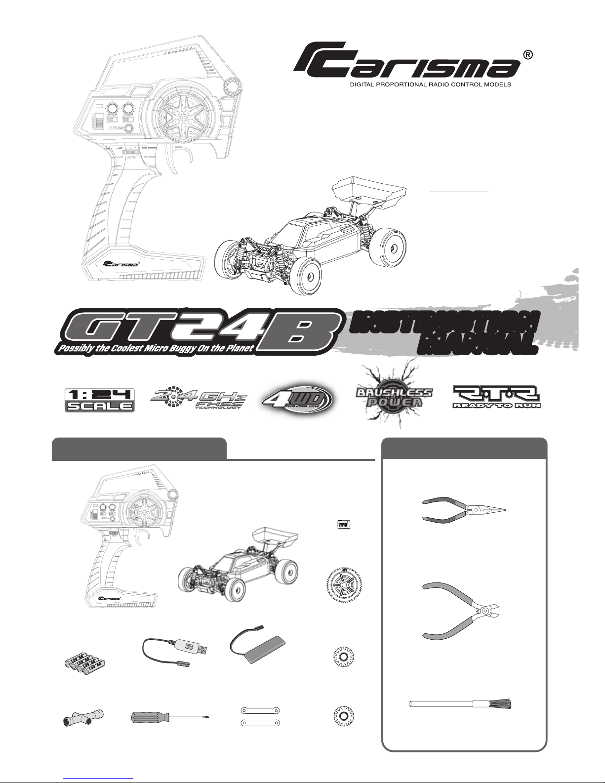
R/C Car
Long Nose Pliers
Nippers
Soft Brush
Screwdrive
(Small)
4 x AA Batteries
Wrench
Transmitter
WHAT’S IN THE BOX
TOOLS RECOMMENED
(NOT INCLUDED)
DIMENSION
SCALE : 1/24
HEIGHT : 64mm
TYRE : ø36mm(width)
LENGTH : 180mm
WIDTH : 107mm
WHEELBASE : 119mm
USB
Charger
3.7V 500mAh
LiPO Rechargeable
Battery Pack
Pinion Gear
13T
Steering
Linkage
Spur Gear
58T
Throttle
Limiter
Pinion Gear
14T
INSTRUCTION
MANUAL
INSTRUCTION
MANUAL
SAFETY PRECAUTIONS
SAFETY PRECAUTIONS
THIS MODEL IS ONLY SUITABLE FOR PEOPLE 14 YEARS OLD AND UP.
THIS RADIO CONTROL MODEL IS NOT A TOY.
Introduction
Safety, Precautions, and Warnings
Beginner should seek advice from experienced person in order to assemble the model or parts correctly and to make best performance.
* Assemble this model or parts only in place out of children’s reach, and take safe precautions before operating this model. User is fully responsible
for the model assembly and safe operations.
This is a sophisticated hobby product and not a toy. It must be operated with caution and common sense. User also requires some basic mechanical
abilities. Fail to operate this product in a safe and responsible manner could result in injury or do damage to the product or other properties. This product
is not intended for use by children without direct adult supervision. The product manual contains instructions for safe operation and maintenance. It is
essential to read and follow all the instructions and warnings in the manual prior to assembly, setup or use, in order to operate correctly and avoid
damage or injury.
As the user of this product, you are solely responsible for operating it in a manner that does not endanger yourself and others or result in damage to
the product or the property of others.
This model is controlled by a radio signal that is subject to interference from many sources outside your control. This interference can cause momentary
loss of control so it is necessary to always keep a safe distance in all directions around your model, as this will help to avoid collisions or injury.
• Always operate your model in an open area away from cars, trac, or people.
• Avoid operating your model on the street where injury or damage can occur.
• Never operate the model out into the street or populated areas for any reason.
• Never operate your model with low transmitter batteries.
• Carefully follow the directions and warnings for this product and any optional support
equipments (chargers, rechargeable battery packs, etc.) that you use.
• Keep all chemicals, small parts and anything electrical out of the reach of children.
• Moisture causes damage to electronics. Avoid water exposure to all equipments not
specifically designed and protected for this purpose.
The associated regulatory agencies of the following countries recognize the noted certifications for this product as authorized for sale and use.
UK
FI
CZ
AT
NL FR
DE
EE
SK
IT
LU
DK
LV
HUES
MT
BG
LT
RO PT
CY
SE
PL
SIIEGR
CE Compliance Information For The European Union
Declaration of Conformity
Products:
Carisma CTX-8000 2.4GHz Transmitter, MRS-24BL Receiver
Equipment Class: 2
The objects of declaration described above are in conformity with the requirements of the specifications listed below.
Manufactured By : Mun Ah Plastic Electronic Toys Company.,Ltd
Statement - This device complies with Part 15 of the FCC Rules.
Operation is subject to the following two conditions:
(1) this device may not cause harmful interference, and
(2) this device must accept any interference received, including interference that may cause undesired operation.
Changes or modifications not expressly approved by the party responsible for compliance could void the user’s authority to operate
the equipment.
FCC ID YDTCTX-8000
Item Name : Carisma CTX-8000 2.4GHz Transmitter and MRS-24BL Receiver
EN 301 489-1 V1.9.2
EN 301 489-17 V2.2.1
ETSI EN 300 328 V1.8.1
Directive 1999/5/EC (R&TTE)
Article 3.1a Health
Article 3.1b EMC
Article 3.2 Radio Spectrum
RF Exposure Warning:
This equipment complies with FCC radiation exposure limits set forth for an uncontrolled environment.
And should be operated with minimum distance of 20 cm between the antenna & your body.
2

ABOUT THE RADIO SYSTEM
CTX-8000
ST. Trim Dial
TH. Trim Dial
* In general, user will experience under steer when making a wide turn at high speed or
over steer when making sharp turn at high speed (easy to spin out). User should practice
the Throttle and steering approach for dierent cornering at dierent speed or road surface.
Battery Installation
The following is an overview of the various functions and adjustments found on CTX-8000 radio system for Carisma models. It is important to read
and understand about all of these functions and adjustments before driving.
Carisma CTX-8000 2.4GHz FHSS Technology System
FUNCTIONS
TRANSMITTER CTX-8000
Steering Wheel : Control direction (Left/Right) of the RC model.
Throttle Trigger : Control speed and direction (Forward/Brake/Backward)
of the driving model.
ON / OFF Switch : Power ON / OFF the transmitter.
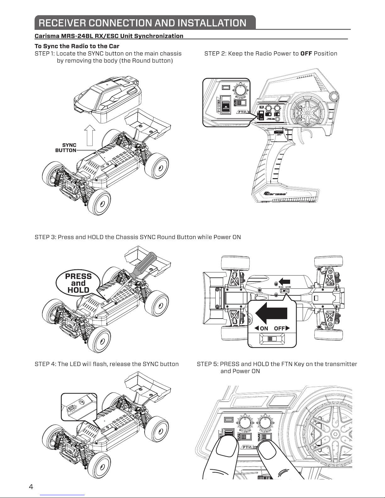
FTN Key : Is used to synchronize the connection between the transmitter and
the receiver. It also serves as additional function on dierent model.
LED Indicator : Green and Red color for indicating battery low, pairing in
progress, End-Points setting and normal operation.
ATV : Adjust the maximum steering angle on both sides when model turns Left /
Right.
ST. Trim Dial : Adjust the neutral position of steering servo when model
wheels are straight ahead.
TH. Trim Dial : To adjust the throttle position
Steering Reverse : Reverse the response direction when operating Steering Wheel.
Throttle Reverse : Reverse the response direction when operating Throttle Trigger.
1. Supplied with 4 x 1.5V AA
Batteries, radio can be
operated a few hours.
Installation: Remove the
battery compartment cover
as shown below.
2.Install the batteries
observing the polarity
marked on battery
compartment.
3.Then reinstall the battery
compartment cover as the
Picture shown below.
Warning :
Never disassemble batteries or put the
batteries in fire, chemical agents, otherwise
they may cause personal injuries or property
damages.
Battery Disposal :
Observe corresponding regulations about
wasted battery treatment regulations.
1. After running out of power, dispose of
wasted batteries in designated areas far
away from water supply, household areas
and planted areas.
2. Submit the wasted batteries to specific
recycling stations.
Battery LED Indicator
The Green LED indicator located on the front left side of the transmitter indicates
the power supply of batteries. The green LED will go solid on indicating that
the batteries have sucient power. When batteries voltage drops below 4
volts, LED will turn to Flashing RED, indicating the batteries power is low and
should be replaced.
Pre-Run Check
Steering
Wheel
Throttle Trigger
LED
Indicator
Steering
Reverse
Throttle
Reverse
ATV
FTN Key
ON/OFF
Switch
* Always turn on the transmitter first by sliding
the switch on the left side from bottom to top.
The small red and green lights above the
switch should both light up. If not, you need
to check for low or incorrectly installed
batteries.
1. Steering : Adjust the steering trim to keep
the front wheels in straight line when steering
wheel remains in NEUTRAL position.
2. Throttle : Adjust the throttle trim to ensure
the rear wheels stop rotating when throttle
trigger remains in NEUTRAL position.
GREENGREEN
Solid GREEN :
Sucient Power supply
Flashing RED :
Time to replace batteries
Reversing
Throttle Limiter
Reversing is used to change the response direction of steering wheel and throttle
trigger. This Transmitter features 2 reversing functions: Steering Reverse and Throttle
Reverse.
Steering Reverse: Reverse the response direction
when operating steering wheel. Turning left steering
wheel, the model turns right while turning right the
model turns left.
Throttle Reverse: Reverse the response direction
when operating throttle trigger. Pushing forward
throttle trigger the model moves backward while
pulling back, the model moves forward. If necessary
you can just use a small screwdriver to adjust the
or responding switches.
Installed the Throttle limiter can reduced
Throttle travel by 30% .
Ideal for beginner.
ATV enables to adjust the maximum steering angle of servo on both sides (Left
and Right) when model makes steering. The ATV aects the sensitivity of servo.
Reducing dual rate value can lower the sensitivity of servo and reduce the same
maximum steering angle on both sides. Remember to adjust the ATV within the
adjustment range.
ATV
ATV
GREEN
Throttle Reverse:
ATV
3
5
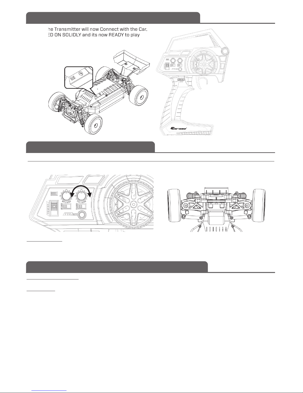
STEP 6: The Transmitter will now Connect with the Car.
STEP 7: LED ON SOLIDLY and its now READY to play
Just use the TH. Trim to locate the Neutral Position. Nothing else to set.
The ESC is a Forward and Brake/Reverse function.
WARNING:
Maximum is 2S LiPo (7.4V) DO NOT EXCEED this voltage, otherwise will
damage and void warranty.
RECEIVER CONNECTION AND INSTALLATION
CARISMA MRS-24BL RX/ESC UNIT FEATURES
MRS-24BL RX/ESC UNIT SETUP
ESC SETUP
Neutral Position
Receiver (RX) Section
ESC Section
Brushless motor : Connect Brushless Motor’s Micro 3-wire connector to the ESC.
Over Voltage Protection: If battery voltage above 8.8V, ESC will STOP operation.
• Auto cut-o voltage:
• 1S LiPo, cut-o voltage = 3.6V
• 2S LiPo, cut-o voltage = 6.6V
Thermal Protection: Temperate at Thermal sensor approx 80~100°C
Motor Overloading and Stall Detection: Cut-o time is depending on Battery voltage, Motor loading condition, Throttle level, etc.
Max Reverse Speed: 50%
Smart Brake: When Throttle move from Forward to Backward, the ESC will apply Brake for certain of time, and then drive motor at Reverse direction.
Similarly for Throttle move from Backward to Forward. The time of Braking inserted is depended on what is the current speed of the motor.
RX Power OFF reminder : After Loss of RF signal over 5 sec., will use LED and servo to warn the user to POWER OFF the car
• LED quickly Flashed 2 times per 2 sec.
• Servo will be moved once shortly per 10 sec.
LED indicator : Indicator the TX is detected.
2.4GHz Receiver : HOLD the SYNC button while power up to start pairing to Transmitter.
Ca
Y and it
Y t
pl
6
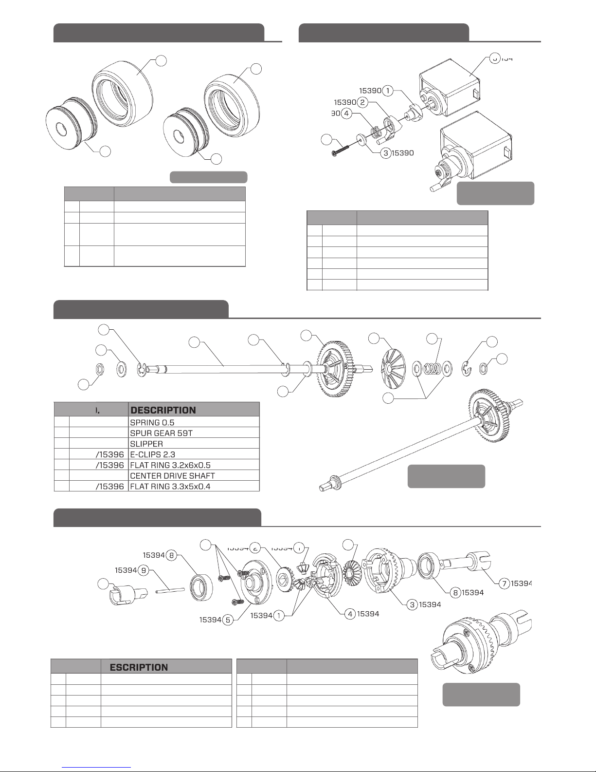
FRONT & REAR WHEEL ASSEMBLY
CENTER DRIVE ASSEMBLY
GEAR DIFFERENTIAL ASSEMBLY
SERVO SAVER ASSEMBLY
1
2
3
4
ITEM NO. DESCRIPTION
15387
15387
38˚ SHORE FRONT TIRE
38˚ SHORE REAR TIRE
GT24B FRONT WHEEL (GREEN)/
GT24B FRONT WHEEL (ORANGE)
1
15387
5
15434
3
15390
15390
1
15390
2
15390
4
15390
6
3
15385 /
15386
4
15385 /
15386
2
15387
15385/
15386
15385/
15386
GT24B REAR WHEEL (GREEN)/
GT24B REAR WHEEL (ORANGE)
1
2
3
4
5
6
ITEM NO. DESCRIPTION
15390
15390
15390
15390
15434
15390
SERVO HORN ADAPTOR
SERVO HORN
SERVO SPACER
SERVO SPRING
MS-24B SERVO
SCREW 1.2x8PB
1
2
3
4
5
ITEM NO. DESCRIPTION
15394
15394
15394
15394
15394
1
2
3
4
5
6
7
ITEM NO. DESCRIPTION
15396
15451
15396
15395/15396
15395/15396
15395
15395/15396
SPRING 0.5
SPUR GEAR 59T
SLIPPER
E-CLIPS 2.3
FLAT RING 3.2x6x0.5
CENTER DRIVE SHAFT
FLAT RING 3.3x5x0.4
9T BEVEL GEAR
21T BEVEL GEAR
DIFFERENTIAL HOUSING A
DIFFERENTIAL HOUSING B
DIFFERENTIAL HOUSING C
6
15394
9
15394
5
15394
4
15394
3
15394
8
15394
7
15394
1
15394
8
15394
2
15394
2
15394
1
15394
10
15394
5
4
6
15395
5
5
15395/
15396
15395/
15396
7
15395/
15396
15395/
15396
15395/
15396
15395/
15396
4
3
15396
2
15451
4
7
15395/
15396
15395/
15396
1
15396
6
7
8
9
10
ITEM NO. DESCRIPTION
15394
15394
15394
15394
15394
DIFFERENTIAL OUTDRIVE(SHORT)
DIFFERENTIAL OUTDRIVE(LONG)
BEARING 6x10x3mm
ADAPTOR PIN
SCREW 1.4x4PB
ASSEMBLED
GT24B-04
ASSEMBLED
GT24B-03
ASSEMBLED
GT24B-02
GT24B-01
 Loading...