

Page 1
ABOUT THE RADIO SYSTEM
INSTRUCTION MANUAL
* In general, user will experience under steer when making a wide turn at high speed or over steer
when making sharp turn at high speed (easy to spin out). User should practice the Throttle and
steering approach for dierent cornering at dierent speed or road surface.
Battery Installation
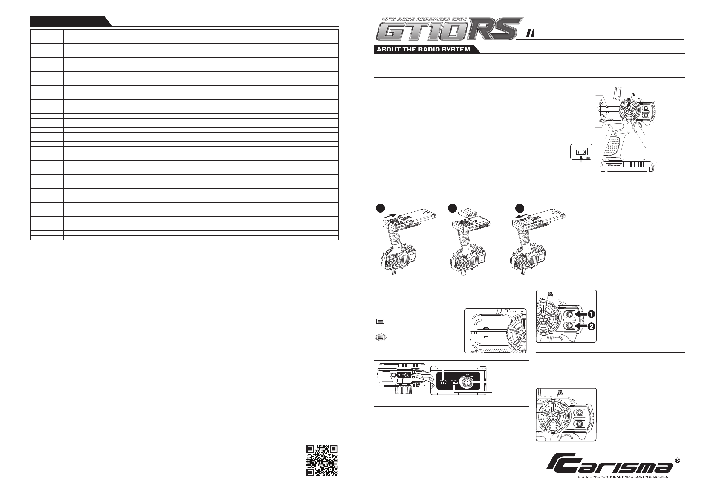
The following is an overview of the various functions and adjustments found on CTX-2710 radio system for Carisma models. It is important to read and understand about all
of these functions and adjustments before driving.
Carisma CTX-2710 2.4GHz FHSS Technology System
FUNCTIONS
TRANSMITTER CTX-2710
Steering Wheel : Control direction (Left / Right) of the RC model.
Throttle Trigger : Control speed and direction (Forward/Brake/Backward) of the driving model.
Antenna : Transmit signal to the model.
Power ON / OFF : Power ON / OFF the transmitter
SYNC & Battery Indicator : Top Green LED light indicates synchronization status and/or adequate
battery power supply.
Power Indicator : Bottom Red LED light indicates Power “ON”.
Dual Rate Dial : Adjust the maximum steering angle on both sides when model turns Left / Right
ST. Trim Dial : Adjust the neutral position of steering servo when model wheels are straight
ahead.
TH. Trim Dial : Make sure the model stays still when releasing the throttle trigger.
Battery Compartment Tray : Cover and hold the batteries powering the transmitter.
1. Supplied with 4 x 1.5V AA Batteries,
radio can be operated a few hours.
Installation: Remove the battery
compartment cover as shown below.
2.Install the batteries observing
the polarity marked on battery
compartment.
3.Then reinstall the battery
compartment cover as the
Picture shown below.
Warning :
Never disassemble batteries or put the batteries
in fire, chemical agents, otherwise they may cause
personal injuries or property damages.
Battery Disposal :
Observe corresponding regulations about wasted
battery treatment regulations.
1. After running out of power, dispose of wasted
batteries in designated areas far away from
water supply, household areas and planted areas.
2. Submit the wasted batteries to specific recycling
stations.
Battery LED Indicator
The Green LED indicator located on the front left side of the transmitter indicates the
power supply of batteries. The green LED will go solid on indicating that the batteries
have sucient power. When batteries voltage drops below 4 volts, LED will turn to
Flashing RED, indicating the batteries power is low and should be replaced.
Pre-Run Check
Trimming
Top Control Panel
Reversing
Dual Rate Dial
* Always turn on the transmitter first by sliding
the switch on the left side from bottom to top.
The small red and green lights above the switch
should both light up. If not, you need to check
for low or incorrectly installed batteries.
1. Steering : Adjust the steering trim to keep the
front wheels in straight line when steering wheel
remains in NEUTRAL position.
2. Throttle : Adjust the throttle trim to ensure
the rear wheels stop rotating when throttle
trigger remains in NEUTRAL position.
Solid GREEN :
Sucient Power supply
Flashing RED :
Time to replace batteries
1
2
3
ST.TRIM
TH.TRIM
CTX-2710
Battery
Compartment
Tray
Steering Trim
Dial
Dual Rate Dial
SYNC
ST.TRIM
TH.TRIM
Steering
Wheel
Throttle
Trigger
Throttle Trim
Dial
Antenna
SYNC and
Battery
Level Indicator
Power
Indicator
Power
ON / OFF
SYNC
SYNC Button
(Synchronization)
ST.TRIM
TH.TRIM
Green
Red
Green
Red
Throttle Reverse
Switch
Reversing is used to change the response direction of steering wheel and throttle trigger.
CTX-2710 Transmitter features 2 reversing functions: Steering Reverse and Throttle Reverse.
Steering Reverse: Reverse the response direction when operating steering wheel.
Turning left steering wheel, the model turns right while turning right the model turns left.
Throttle Reverse: Reverse the response direction when operating throttle trigger.
Pushing forward throttle trigger the model moves backward while pulling back, the
model moves forward. If necessary you can just use a small screwdriver to adjust the
or responding switches.
CTX-2710 features two trimming functions:
Steering Trim and Throttle Trim.
Steering Trim Dial :
Adjust the neutral position of steering servo
when the wheels are straight ahead.
Normally steering trim is adjusted until the
model can keep straight tracks.
Throttle Trim Dial :
Adjust neutral position of throttle servo.
Make sure the model stays still when
releasing the throttle trigger.
Dual Rate Dial enables to adjust the same maximum steering angle of servo on both
sides (Left and Right) when model makes steering. The Dual Rate Dial aects the
sensitivity of servo. Reducing dual rate value can lower the sensitivity of servo and
reduce the same maximum steering angle on both sides. Remember to adjust the
dual rate value within the adjustment range.
Steering Reverse
Switch
Dual Rate Dial
ITEM NO. PRODUCT NAME
SPARE PARTS LIST
14103
14104
14114
14129
14130
14131
14139
14986
14994
15015
15224
15239
15339
15340
15343
15347
15348
15349
15350
15352
15354
15355
15356
15357
15358
15362
15363
15364
15367
15368
15369
15370
15371
15373
15374
15376
15378
15379
15437
15438
15440
15441
15443
15444
FRONT HUB/STEERING ARM SET
REAR HUB SET
STEERING POST SET
LOCK NUT (4MM AND 3MM)
BALL BEARING 4X10X3 AND 8X12X3.5
BALL BEARING 5X11X4
SPUR GEAR 72T
WHEEL HEX/DRIVE PIN SET
HINGE PIN BRACE SET
METAL MAIN DRIVE SHAFT FOR METAL DIFFERENTIAL GEAR
BODY CLIP SET (S/M/L)
INPUT GEAR SHAFT SET (F/R)
GT10RS MERCEDES-AMG C-COUPE DTM 2014 (WHITE) CAR BODY PAINTED AND DECORATED BODY
GT10RS MERCEDES-AMG C-COUPE DTM 2014 (RED) CAR BODY PAINTED AND DECORATED BODY
GT10RS MERCEDES-AMG C-COUPE DTM 2014 (RED) CLEAR CAR BODY
GT10RS MERCEDES-AMG C-COUPE DTM 2014 CAR BODY PLASTIC PARTS + REAR BUMPER SET
GT10RS MERCEDES-AMG C-COUPE DTM 2014 FRONT BUMPER SET
GT10RS FRONT SHOCK ASSEMBLED (PR.)
GT10RS REAR SHOCK ASSEMBLED (PR.)
PINION GEAR 24T
GT10RS FRONT DOG BONE PAIR
GT10RS REAR DOG BONE PAIR
GT10RS DIFFERENTIAL OUTDRIVE SET
GT10RS OUTDRIVE
GT10RS THREAD ROD SET
GT10RS SLIPPER SET
GT10RS MERCEDES-AMG C-COUPE DTM 2014 (WHITE) CLEAR CAR BODY
GT10RS SUSPENSION PIN SET
MRS-540BL SERVO + RECEIVER +ESC UNIT
SERVO MS-1135W
GT10RS MERCEDES-AMG C-COUPE DTM 2014 LED ASSEMBLE
GT10RS DIFF. GEAR SET
GT10RS AUDI RS5 DTM 2014 ( RED) CAR BODY PAINTED AND DECORATED BODY
GT10RS AUDI RS5 DTM 2014 CAR BODY PLASTIC PARTS + REAR BUMPER SET
GT10RS AUDI RS5 DTM 2014 (RED) CLEAR CAR BODY
GT10RS AUDI RS5 DTM 2014 WHEEL ASSEMBELED (PAIR)
GT10RS AUDI RS5 DTM 2014 FRONT BUMPER SET
GT10RS AUDI RS5 DTM 2014 LED ASSEMBLE
GT10RS BMW M4 DTM 2014 ( WHITE ) CAR BODY PAINTED AND DECORATED BODY
GT10RS BMW M4 DTM 2014 CAR BODY PLASTIC PARTS + REAR BUMPER SET
GT10RS BMW M4 DTM 2014 ( WHITE ) CLEAR CAR BODY
GT10RS BMW M4 DTM 2014 WHEEL ASSEMBELED (PAIR)
GT10RS BMW M4 DTM 2014 FRONT BUMPER SET
GT10RS BMW M4 DTM 2014 LED ASSEMBLE
Printed in China
MAN-G00607
©2015 Carisma. All Rights Reserved. Product specifications are subject to change.
Some models shown are prototypes which may vary slightly from what is inside.
Visit Us on
Also avaliable at
www.carisma.com.hk
www.carisma-shop.com
Page 2
14097
14110
14105
15370
15370
15370
15370
14105
15370
15370
15370/15356
15355
15364
15239
15362
15362
15362
15362
15362
15362
14130
15453
15018
14131
14101
15350
15357
14110
14104
14131
14124
14124
14111
14106
14107
15364
14018
14018
14018
14994
14129
14994
14138
14110
14110
14103
14131
14124
14124
15367
14139
15018
14142
14098
14142
14111
14111
15278
MASM2504A
SSW-G00190
SSW-G00209
Front Turnbuckle
SSW-G00188
SSW-G00652
SSW-G00188
SSW-G00188
SSW-G00207
SSW-G00188
SSW-G00188
SSW-G00207
SSW-G00188
SSW-G00281
SSW-G00207
SSW-G00188
SSW-G00207
SSW-G00207
MASM2504A
SSW-G00281
SSW-G00188
SSW-G00209
Steering Turnbuckle
SSW-G00652
Servo
DCL-G00233
SSW-G00272
SSW-G00106
SSW-G00129
SSW-G00129
Rear Turnbuckle
SSW-G00233
SSW-G00201
SSW-G00201
MASM1011A
EVA-G00121
RBT-G00025
SSW-G00376
MASM2504A
MASM2504A
R14P1111
RBT-G00025
MASM1011A
EVA-G00121
SSW-G00192
SSW-G00192
SSW-G00267
15345
15441
15376
ITEM NO.
MERCEDES AMG C-COUPE DTM
AUDI RS5 DTM
BMW M4 DTM
15301
SUBARU WRX STi NBR
15453 VOLKSWAGEN GOLF 24
15345
15441
15376
ITEM NO.
MERCEDES AMG C-COUPE DTM
AUDI RS5 DTM
BMW M4 DTM
15301
SUBARU WRX STi NBR
15453 VOLKSWAGEN GOLF 24
15347
15438
15373
ITEM NO.
MERCEDES AMG C-COUPE DTM
AUDI RS5 DTM
BMW M4 DTM
15298 SUBARU WRX STi NBR
15065 VOLKSWAGEN GOLF 24
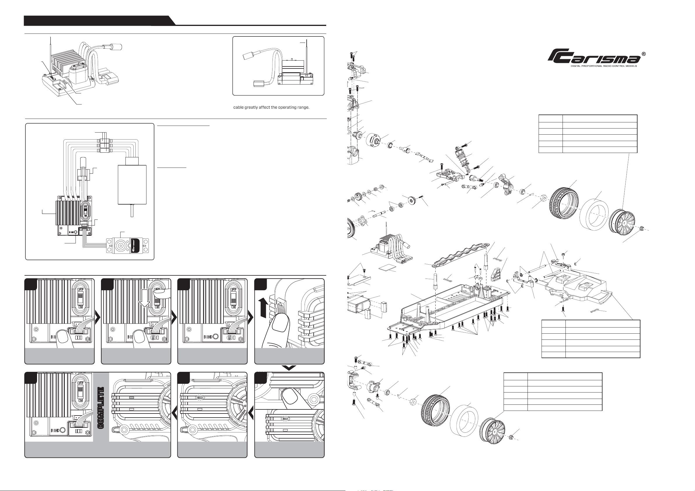
RECEIVER CONNECTION AND INSTALLATION
Receiver Unit
MRS-540BL
Bind Button
5 wires Servo
MS-1135W
Auxiliary Port
(3 Pin)
(Reserved)
XT60
Battery
Connector
Bullet
Connector
Carisma MRS-540BL RX/ESC Unit
Receiver (RX) Section
2.4GHz 2 Channels receiver
Compatible with Carisma 2CH FHSS radio, (eg. CTX-2710, CTX-2810, CTX-8000)
(Please refer "Binding Flow Chart")
540 BRUSHLESS
MOTOR
Bind
Button
Antenna Cable
Remarks :
The mounting positions of receiver and antenna
Install the antenna vertically to the ground.
Auxiliary Port (3 Pin)(Reserved):
Where to plug optional standard 3 wires servo
or use as LED port.
Bind Button :
Synchronize transmitter and receiver.
Warning :
• Never bend the metal pins on the PCB of receiver.
• Never cut the antenna cable.
• Install the antenna vertically as shown in the figure.
• Keep the antenna as far away from the motor,
ESC and other noise sources as you possibly can.
6
PRESS and HOLD the BIND key of
Receiver unit
Power ON the unit, GREEN LED
Flashes
Release the BIND key, GREEN LED
Flashing waiting for transmitter
to bind.
1
7
2 3 4
Release the SYNC key.
WAIT until the Receiver Unit and the Transmitter’s GREEN LED are both
Solid ON, indicate the binding process is completed.
Receiver / ESC Unit Features
ESC Section
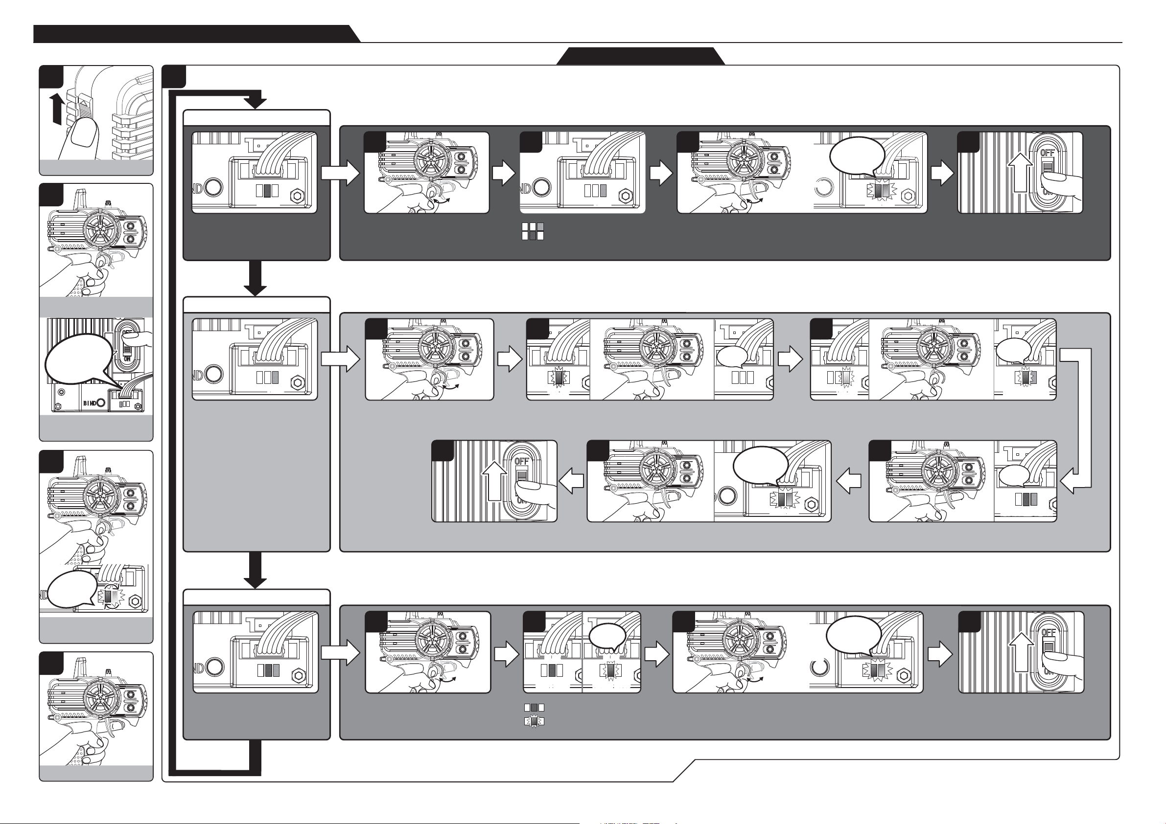
Programmable (Please refer to page 6 “ESC Setup Flow Chart”)
• Programmable Battery Type: NiHM or LiPO
• End Points Calibration
• ESC mode
- Forward / Reverse with Smart Brake
- Forward Only with Brake
Thermal Protection
Stall Protection
Over and Under Voltage Protection
LED indicator
• Just after Power ON
LED will be flashed for 2 seconds to indicate the currently selected battery type instantly:
Flashing BLUE LED, Battery = NiMH
Flashing RED LED, Battery = LiPO
• Normal Operation
Neutral: BLUE LED Solid ON (Forward / Reverse with Smart Brake)
Flashing BLUE LED (Forward Only with Brake)
Forward (NOT Full Speed): RED and BLUE LED OFF
Forward (Full Speed): RED LED ON
Reversing (NOT Full Speed): RED and BLUE LED OFF
Reversing (Full Speed): BLUE LED ON
Brake: RED and BLUE LED ON
Auxiliary Port (3 Pin)
(Reserved)
5 Wires Servo Port
Integrated Servo controller, 5 wire / Option 3 wire servo port / LED Port
When unit is just Power ON, it will check whether a 5 wire servo MS-1135W is connected
or not. If servo MS-1135W is connected, the 3 wire port will become Brake LED port
(Only Carisma LED set can be used for this port). Else, the 3 wire port will become 3 wire
servo port.
Binding Flow Chart
MS-1135W
Power ON the transmitter
PRESS and HOLD the SYNC button.
GREEN LED flashes indicate the tranmitter
is communicating with the Receiver Unit
5
COMPLETECOMPLETE
NOTE: IF BINDING PROCESS FAIL, REPEAT FROM STEP 1 AND TRY AGAIN.
Page 3
14097
14110
14110
14105
15370
15370
15370
15370
15370
15024
14130
14989
15356
15370
14105
15370
15370
15370/15356
15355
15364
15239
15362
15362
15362
15362
15024
15362
15362
15362
14130
14106
15001
15001
15001
15453
15018
14131
14101
15350
15357
14110
14104
14131
14124
14124
14111
14106
14107
15364
14018
14018
14018
14994
14129
14994
14108
14108
14018
15364
14994
14994
14018
14105
15024
15024
15024
15024
15024
15024
15024
15024
15356
14100
14131
14103
14138
14138
14110
14110
14103
14131
14124
14124
15364
15354
15357
15024
15024
15024
15024
14105
14097
14110
14115
14115
14110
14110
14106
14114
14114
14114
15015
15024
15191
15024
15024
15024
15278
15278
15278
15367
14139
14130
15018
14110
14142
14098
14142
14111
14111
15278
15278
15278
15278
15279
15024
15110
15356
14130
15024
14130
14130
15364
14129
MASM2504A
SSW-G00190
SSW-G00209
Front Turnbuckle
SSW-G00188
SSW-G00652
SSW-G00188
SSW-G00188
SSW-G00207
SSW-G00188
SSW-G00188
SSW-G00207
SSW-G00188
SSW-G00281
SSW-G00207
SSW-G00188
SSW-G00207
SSW-G00207
MASM2504A
SSW-G00281
SSW-G00188
SSW-G00209
Steering Turnbuckle
SSW-G00652
Front Oil Shock
SSW-G00129
SSW-G00201
SSW-G00129
SSW-G00233
SSW-G00201
R14P1111
R14P1111
SSW-G00156
SSW-G00156
SSW-G00192
SSW-G00192
SSW-G00190
EVA-G00195
M40P0505
MASM2504A
SSW-G00106
SSW-G00188
SSW-G00192
SSW-G00192
SSW-G00192
SSW-G00192
Servo Turnbuckle
SSW-G00196
SSW-G00196
Servo
DCL-G00233
SSW-G00272
SSW-G00267
SSW-G00106
SSW-G00129
SSW-G00129
Rear Turnbuckle
SSW-G00233
SSW-G00201
SSW-G00201
MASM1011A
EVA-G00121
RBT-G00025
SSW-G00376
MASM2504A
MASM2504A
R14P1111
RBT-G00025
MASM1011A
EVA-G00121
SSW-G00140
SSW-G00158
SSW-G00235
SSW-G00192
SSW-G00192
SSW-G00235
SSW-G00192
SSW-G00192
SSW-G00235
SSW-G00193
SSW-G00193
SSW-G00235
SSW-G00156
SSW-G00156
SSW-G00188
SSW-G00192
SSW-G00192
SSW-G00192
SSW-G00192
SSW-G00193
SSW-G00267
SSW-G00272
15345
15441
15376
ITEM NO.
MERCEDES AMG C-COUPE DTM
AUDI RS5 DTM
BMW M4 DTM
15301
SUBARU WRX STi NBR
15453 VOLKSWAGEN GOLF 24
15345
15441
15376
ITEM NO.
MERCEDES AMG C-COUPE DTM
AUDI RS5 DTM
BMW M4 DTM
15301
SUBARU WRX STi NBR
15453 VOLKSWAGEN GOLF 24
15347
15438
15373
ITEM NO.
MERCEDES AMG C-COUPE DTM
AUDI RS5 DTM
BMW M4 DTM
15298 SUBARU WRX STi NBR
15065 VOLKSWAGEN GOLF 24
15348
15443
15378
ITEM NO.
MERCEDES AMG C-COUPE DTM
AUDI RS5 DTM
BMW M4 DTM
15297 SUBARU WRX STi NBR
14984 VOLKSWAGEN GOLF 24
15348
15443
15378
ITEM NO.
MERCEDES AMG C-COUPE DTM
AUDI RS5 DTM
BMW M4 DTM
14102 SUBARU WRX STi NBR
15065 VOLKSWAGEN GOLF 24
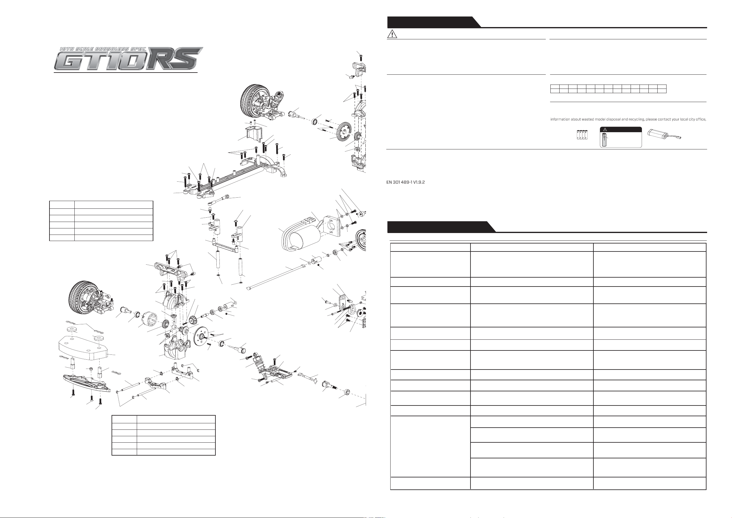
EXPLODED DIAGRAM
SAFETY PRECAUTIONS
TROUBLE SHOOTING GUIDE
This product must never be thrown away with other waste. Thus the users are liable for disposing
the wasted model by submitting them to designated collection stations specific for recycling
electronic and electric items. Disposing of the wasted model in this way is helpful to conserve
natural resources and enable to keep human health and protect the environment. For more
your disposal service or where you purchased the product.
Instructions for Disposal of WEEE by Users in the European Union
Safety Precautions
THIS MODEL IS ONLY SUITABLE FOR PEOPLE 14 YEARS OLD AND UP.
THIS RADIO CONTROL MODEL IS NOT A TOY.
Beginner should seek advice from experienced person in order to assemble the model
or parts correctly and to make best performance.
* Assemble this model or parts only in place out of children’s reach, and take safe precautions
before operating this model. User is fully responsible for the model assembly and safe operations.
This is a sophisticated hobby product and not a toy. It must be operated with caution and
common sense. User also requires some basic mechanical abilities. Fail to operate this
product in a safe and responsible manner could result in injury or do damage to the product
or other properties. This product is not intended for use by children without direct adult
supervision. The product ma
nual contains instructions for safe operation and maintenance.
It is essential to read and follow all the instructions and warnings in the manual prior to
assembly, setup or use, in order to operate correctly and avoid damage or injury.
UK
FI
CZ
AT
NL FR
DE
EE
SK
IT LU
DK
LV
HUES
MT
BG
LT
RO PT
CY
SE
PL
SI IEGR
The associated regulatory agencies of the following countries recognize the noted certifications
for this product as authorized for sale and use.
Declaration of Conformity
Products: Carisma CTX-2710 2.4GHz Transmitter, MRS-540BL Receiver
Equipment Class: 2
The objects of declaration described above are in conformity with the
requirements of the specifications listed below.
Statement - This device complies with Part 15 of the FCC Rules.
Operation is subject to the following two conditions:
(1) this device may not cause harmful interference, and
(2) this device must accept any interference received, including interference
that may cause undesired operation.
FCC ID YDTMTM27HP
RF Exposure Warning:
This equipment complies with FCC radiation exposure limits set forth for an
uncontrolled environment.
And s hould be operated with minimum distance of 20 cm between the
antenna & your bod y.
Item Name : Carisma CTX-2710 2.4GHz Transmitter and MRS-540BL Receiver
EN 301 489-17 V2.2.1
ETSI EN 300 328 V1.8.1
Introduction
Safety, Precautions, and Warnings CE Compliance Information For The European Union
As the user of this product, you are solely responsible for operating it in a manner that does not
endanger yourself and others or result in damage to the product or the property of others.
This model is co ntrolled by a radio sig nal that is subject to interfer ence from many sources
outside your control. This interference can cause momentary loss of control so it is necessary
to always keep a safe distance in all directions around your model, as this will help to avoid collisions or injury.
• Always operate your model in an open area away from cars, trac, or people.
• Avoid operating your model on the street where injury or damage can occur.
• Never operate the model out into the street or populated areas for any reason.
• Never operate your model with low transmitter batteries.
• Carefully follow the directions and warnings for this product and any optional support
equipments (chargers, rechargeable battery packs, etc.) that you use.
• Keep all chemicals, small parts and anything electrical out of the reach of children.
• Moisture causes damage to electronics. Avoid water exposure to all equipments not
specifically designed and protected for this purpose.
Changes or modifications not expressly approved by the party responsible for
compliance could void the user’s authority to operate the equipment.
Directive 1999/5/EC (R&TTE)
Article 3.1a Health
Article 3.1b EMC
Article 3.2 Radio Spectrum
FOR TRANSMITTER
Damages or Leaking.
Do not use any damaged
batteries.
x4
Heavy Duty
1.5V “AA” Size Batteries
(INCLUDED)
ATTENTION
Car Battery
(NOT INCLUDED)
Trouble Shooting
Problem Possible Cause Solution
Receiver Unit
NO Function
• Signal Loss
• Green LED flashes quickly 2 times, turn OFF for
a while and repeat again.
3 wire servo NO Function 5 wire servo is connected
• Check if the transmitter is Power OFF.
Power OFF the unit. Disconnect 5 wire
servo and power on the unit.
• Overheat Protection :
RED and BLUE LED alternative flashing quickly
WAIT until the Unit cool down completely
WAIT until the Unit cool down completely
• Motor Stalled Protection :
RED LED flashes quickly 3 times, Turn OFF for a
while and Repeat again.
Replace battery pack
Replace battery pack
• Over Voltage Protection (Battery over 13V) :
RED LED SOLID ON and BLUE LED Flashing ONCE
per second
ESC NO Function
• Under Voltage Protection (Battery under 10.2V
for 3S LiPO / 6.8V for 2S LiPO / 4.8V for NiHM) :
BLUE LED SOLID ON and RED LED Flashing ONCE
per second
ESC NO Reverse Function
• ESC mode "Racing Mode" is selected
BLUE LED Flashing at STOP position
Select ESC Sport / Racing mode according
to Page 6 "ESC Setup Flow Chart"
Short run time /
Running slow
• Battery not fully charged
• Battery power has run down
• Motor gets dirty or worn out
• Wheel nuts are over tightened
• Dust or other objects are inside the gears
• Bind drivetrain
• Transmitter battery low
• Transmitter antenna not pointing upward
• Battery power has run down
• Receiver antenna Cut / Worn
• Steering trim is not adjusted correctly
• Fully recharge batteries
• Replace new batteries
• Clean / Replace the damaged part of motor
• Slightly loosen the wheel nuts
• Clean the gears
• Full check all drive trainparts
Don’t Run straight
Model doesn’t stop when
throttle trigger stay at
“ Neutral ” position
• Adjust the steering trim on the transmitter.
• Throttle trim is not adjusted correctly • Adjust the throttle trim on the transmitter
Model doesn’t operate
• Transmitter batteries have run down
• Transmitter not switched on
• ESC / Receiver not switched on
• Battery power has run down
• Poor synchronization of transmitter and receiver
• Replace new AA alkaline batteries
• Turn on the transmitter
• Switch on the ESC / Receiv
er
• Replace new batteries
• Resynchronize transmitter and receiver
• Check / Replace new AA batteries
• Let antenna pointing upward
• Charge up the battery and retry
• Check if properly attaching or repair if necessary
Poor operating range
Lose Control
Steering doesn’t work
• Batteries have run down
• Receiver antenna Cut / Worn
• Servo gears damaged
• Servo Saver Broken
• Replace a new servo
• Replace new servo saver
• Check / Replace new batteries
• Check Receiver Antenna
Improper setting of steering reverse switch
Reversed transmitter
steering direction
Reversed transmitter
throttle direction
Check throttle reverse switch and set to the
opposite side.
Improper setting of throttle reverse switch
Check steering reverse switch and set to the
opposite side.
Page 4
ST.TRIM
TH.TRIM
ST.TRIM
TH.TRIM
ST.TRIM
TH.TRIM
RECEIVER / ESC UNIT (MRS-540BL) FUNCTIONS
ST.TRIM
TH.TRIM
ST.TRIM
TH.TRIM
ST.TRIM
TH.TRIM
ST.TRIM
TH.TRIM
ST.TRIM
TH.TRIM
ST.TRIM
TH.TRIM
ST.TRIM
TH.TRIM
ST.TRIM
TH.TRIM
ST.TRIM
TH.TRIM
ENTER SETUP MODE (SWITCH OFF THE MRS-540BL BEFORE ENTER SETUP MODE)
1
5
BATTERY TYPE SELECTION MODE
1
Power ON the Transmitter
2
PULL
BLUE LED ON
(Indicate “Select Battery Type”)
Pull the Throttle Trigger to Max. Forward
position to toggle Battery type
APPROX 2 sec.
HOLD the Throttle Trigger to
Max. Forward Position
CALIBRATION MODE
1
SETUP FLOW CHART
2
REDRED REDREDBLUEBLUE BLUEBLUE
Display CURRENT Battery type instantly
RED LED ON = LiPO Battery
BLUE LED ON = NiHM Battery
2
3
After
After
4 Second
4 Second
FLASHES
3 TIMES WITH
3 “BEEP”
SOUND
1. When Battery type has been Selected, RELEASE the Throttle Trigger to
Neutral position.
2. After 4 second, selection made with RED and BLUE LED Flashes
3 times with 3 “BEEP“ sound, Battery Select has been completed.
3
4
Power OFF the Receiver Unit to Escape
from Setup mode.
GREEN LED
FLASHING
THEN TRUN
SOLID
Power ON Receiver Unit
(MRS-540BL)
3
“BEEP”
HOLD the Throttle Trigger until
RED & BLUE LED Alternatively
Flashing with a “BEEP” sound
4
Release Throttle Trigger
REDRED
RED LED ON
(Indicate “Calibration Mode”)
APPROX 2 sec.
ESC SPORT / RACING MODE
RED
REDBLUEBLUE
RED and BLUE LED ON
(Indicate “Select ESC Mode”)
APPROX 2 sec.
PULL
Pull the Throttle Trigger to Max. Forward
position.
RED LED OFF and BLUE LED Flashes
6
Power OFF the Receiver Unit to Escape
from Setup mode.
1
PULL
Pull the Throttle Trigger to Max.
Forward position and then release
“BEEP”
Blue LED
Blue LED
Flashes
Flashes
Neutral
Position
Release Throttle Trigger to Neutral position
BLUE LED SOLID ON with a “BEEP” Sound, then BLUE LED OFF
Throttle Neutral Position has been set.
5
3 times with
Neutral
Position
Release Throttle Trigger to Neutral position
RED and BLUE LED FLASHES 3 times with 3 “BEEP” sound.
Calibration has been completed.
2
BLUE LED
Flashes
BLUEBLUEBLUEBLUE
Sport ModeSport Mode Racing ModeRacing Mode
Display CURRENT ESC Mode instantly
Sport Mode : BLUE LED ON =
Forward/Reverse with Smart Brake
Racing Mode : BLUE LED FLASHES =
Forward Only with Brake
3
Pull the Throttle Trigger to Max. Forward position to toggle ESC mode.
When ESC mode is selected, RELEASE Throttle Trigger.
After 4 second, RED and BLUE LED FLASHES 3 times with 3 “Beep”
sound. ESC mode setup has been completed.
If Fail to Pair, Suggest to Repeat From Begin to Try Again
Flashes
3 “BEEP”
Sound
Neutral
Position
Red LED
Red LED
Flashes
Flashes
PULL
Then RED LED FLASHES Pull the Throttle Trigger to Max. Forward
position. RED LED SOLID ON and BLUE LED FLASHES with a “BEEP”
sound Max Forward has been set.
4
RED
REDBLUEBLUE
4 Second
4 Second
After
After
Push the Throttle Trigger to Max. Reverse position.
RED and BLUE LED SOLID ON with a “BEEP” sound.
Max. Reverse has been set.
FLASHES
3 TIMES WITH
3 “BEEP”
SOUND
PUSH
4
Power OFF the Receiver Unit to
Escape from Setup mode.
“BEEP”
Blue LED Flashes
Blue LED Flashes
Red LED Solid ON
Red LED Solid ON
“BEEP”
Blue & Red LED Solid ONBlue & Red LED Solid ON
 Loading...