

Page 1
Page 2

TABLE OF CONTENTS
Preface .................................................................................................................................. pag. 6
Preliminary warnings ............................................................................................................... pag. 6
1.0 Presentation of the Thermo Fireplace CARINCI .........................................................pag. 7
1.1 Technical specifications and dimensions of the Thermo Fireplace CARINCI SYSTEM ........................ pag. 8
1.2 Combustion chamber ............................................................................................................... pag. 10
2.0 Positioning of the Thermo Fireplace inside the room ................................................pag. 11
2.1 Displacement of the Thermo Fireplace ....................................................................................... pag. 11
2.2 Checking the bearing plate ...................................................................................................... pag. 11
2.3 Checking the walls adjacent to the Thermo Fireplace. .................................................................. pag. 11
3.0 Flue ........................................................................................................................pag. 12
3.1 Flue functions .......................................................................................................................... Pag. 13
3.2 Flue features .......................................................................................................................... pag. 13
3.3 Chimney stack ........................................................................................................................ pag. 14
4.0 Air scoop ................................................................................................................pag. 15
5.0 Presentation of the Thermo Fireplace CARINCI EVOLUTION SYSTEM ..........................pag. 16
5.1 Technical specifications and dimensions of the Thermo Fireplace CARINCI EVOLUTION SYSTEM ..... pag. 17
5.2 KIT SYSTEM position on the Thermo Fireplace CARINCI EVOLUTION ............................................ pag. 17
6.0 Installation of the Thermo Fireplace CARINCI EVOLUTION.........................................pag. 18
6.1 Open-vented simple installation diagram .................................................................................... pag. 18
6.2 Expansion vessel ..................................................................................................................... pag. 19
6.3 Sanitary hot water ................................................................................................................... pag. 19
6.4 Process control and shut-off valve .............................................................................................. pag. 19
6.5 Check valve ........................................................................................................................... pag. 19
6.6 Filling the Thermo Fireplace ...................................................................................................... pag. 19
6.7 Suction .................................................................................................................................. pag. 19
6.8 Water hammer ....................................................................................................................... pag. 19
6.9 Installation instructions for the Thermo Fireplace CARINCI SYSTEM or IDROKIT............................... pag. 19
6.10 Installation combined with a gas boiler
6.10 Installation combined with a gas boiler
6.12 Installation combined with a gas boiler
(Equipped with expansion tank and safety valve) [for SYSTEM and IDROKIT] ...................... pag. 20
(not equipped with expansion vessel and safety discharge valve) [for SYSTEM and IDROKIT] ........ pag. 20
[for SYSTEM and IDROKIT] ............................................................... pag. 20
6.13 Double circuit installation with CARINCI IDROKIT ....................................................................... pag. 22
6.14 Installation of the inspection grill on the hood ............................................................................. pag. 23
6.15 Installation of the inspection side door (to Thermo Fireplace CARINCI SYSTEM) .............................. pag. 23
6.16 Overflow pipe for the expansion tank ........................................................................................ pag. 23
Page 3

6.17 Advice for the installer ............................................................................................................. pag. 23
6.18 Advice for the user .................................................................................................................. pag. 23
6.19 Electronic control unit of the Thermo Fireplace CARINCI .............................................................. pag. 24
6.20 Electronic control unit of the Thermo Fireplace CARINCI SYSTEM .................................................. pag. 26
7.0 First start-up with wood burning of THERMO FIREPLACE CARINCI .............................pag. 26
7.1 Fuel quality ............................................................................................................................ pag. 26
7.2 Fuel dimensions ...................................................................................................................... pag. 27
8.0 Adjustments ............................................................................................................pag. 27
8.1 Circulator adjustment and system balancing ............................................................................... pag. 27
8.2 Combustion adjustment ............................................................................................................ pag. 27
8.3 Secondary air adjustment......................................................................................................... pag. 29
8.4 Tertiary air adjustment ............................................................................................................. pag. 29
8.5 Inspections ............................................................................................................................. pag. 30
8.6 Proper functioning ................................................................................................................... pag. 30
9.0 Covering .................................................................................................................pag. 30
10.0 Recommendations for use .......................................................................................pag. 31
10.1 Using the Thermo Fireplace CARINCI EVOLUTION in adverse weather conditions .......................... pag. 31
10.2 Door opening ......................................................................................................................... pag. 31
10.3 Use of the Thermo Fireplace CARINCI EVOLUTION with open door .............................................. pag. 31
10.4 Sudden switching-off of Thermo Fireplace CARINCI EVOLUTION .................................................. pag. 31
10.5 Overheating ........................................................................................................................... pag. 31
10.6 Possible malfunctions ............................................................................................................... pag. 31
11.0 Cleaning of the Thermo Fireplace CARINCI ...............................................................pag. 31
11.1 Glass cleaning ........................................................................................................................ pag. 31
11.2 Boiler compartment ................................................................................................................. pag 31
12.0 Routine maintenance ...............................................................................................pag. 32
12.1 Heat exchangers cleaning ........................................................................................................ pag. 32
12.2 Proper functioning verification .................................................................................................. pag. 34
13.0 Extraordinary maintenance .....................................................................................pag. 34
13.1 Glass replacement .................................................................................................................. pag. 34
13.2 Handle replacement ................................................................................................................ pag. 34
13.3 Sliding mechanism lock ........................................................................................................... pag. 35
14.0 Technical specifications ............................................................................................pag. 36
Certification of warranty .......................................................................................................... pag. 38
Page 4

heating system innovations
FOREWORD
Dear Customer, Carinci Group S.p.A. thanks you for having chosen the Innovative Thermo Fireplace
CARINCI EVOLUTION, the last technological innovation in the heating industry.
The new Thermo Fireplace is available in two versions ,EVOLUTION G with cast iron-covered
combustion chamber and EVOLUTION R , with refractory material-covered combustion chamber
.
This Manual provides all the information and practical recommendations for the correct installation, use
and maintenance of the product in compliance with the regulations in force.
PRELIMINARY WARNINGS
a) Each local regulation, including those referring to National and European Standards, must be re-
spected during the installation of the appliance;
b) Do not use the appliance as an incinerator or in any way other than for its intended purposes;
c) Do not use fuels other than the ones recommended;
d) Do not use liquid fuels;
e) When operating, the boiler, and particularly its external surfaces, reach very high temperatures;
handle with care when touching to avoid scalding;
f) Do not perform any unauthorized modification on the appliance;
g) Only use original spare parts as recommended by the manufacturer;
h) In the case of the flue catching fire, close the Thermo Fireplace door and use a wet fireproof fabric
to block up the airshaft window (air inlet) located in the upper part of the door and wait for the
combustion to extinguish.
i) To avoid any holes in the boiler body, it is necessary to install adequate protection against power
streams like electrochemical, electrostatic, etc.
4
Page 5
The only real alternative
to the same old thermo fireplace
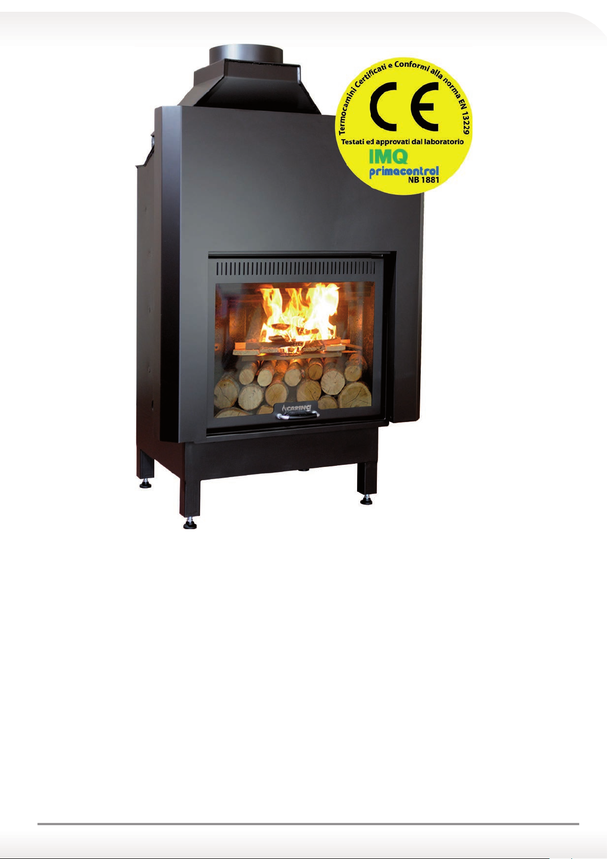
1.0 PRODUCT PRESENTATION
The CARINCI EVOLUTION Thermo Fireplace is built to satisfy the needs of the customer. Its design allows the placement
in any environment. The innovation of our product is in the technical enhancements, which provide an efficiency like
no other.
The CARINCI Thermo Fireplace, in fact, has been designed as a real boiler for sanitary hot water production and as
a heating appliance.
The boiler, inside which the water (thermo courier fluid) circulates, uses special exchangers located within
the combustion chamber, easy to inspect for their cleaning.
These exchangers ensure proper circulation of thermo courier fluid even at very high temperatures, eliminating the bother
of the boiling noise and ensuring the maximum safety of the user in any condition, even during a temporary lack of power.
The efficiency is optimized by the presence of an “air restrictor” located in the upper-front of the Thermo Fireplace-boiler that
allows the entrance of premixed air, giving rise to a steady and homogeneous flame. Also the base of the Thermo Fireplaceboiler affects the yield being made of refractory (fire-resistant) bricks 1350°C vertically positioned with 11 cm thickness
gauge, allowing it to maintain a constant temperature.
5
Page 6
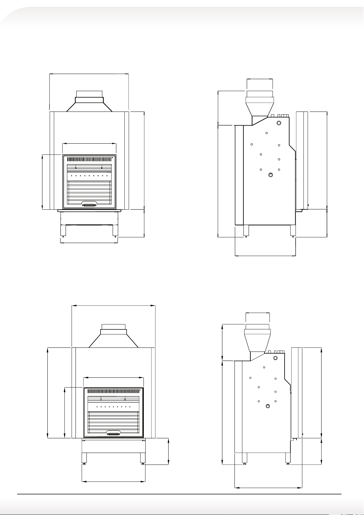
1.1 THERMO FIREPLACE CARINCI TECHNICAL SPECIFICATIONS AND DIMENSIONS
589
768
880
THERMO FIREPLACE CARINCI EVOLUTION Mod. 150
FRONT VIEW AND SIDE VIEW
250
334
522
533
950
1087
269
557
THERMO FIREPLACE CARINCI EVOLUTION Mod. 200
FRONT VIEW AND SIDE VIEW
250
1219
269
380
632
950
533
280
667
6
1090
710
950
280
Page 7
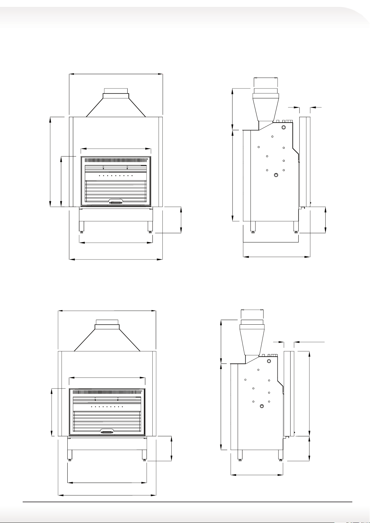
990
250
1100
THERMO FIREPLACE CARINCI EVOLUTION Mod. 250
FRONT VIEW AND SIDE VIEW
250
440
742
110
950
965
533
278
777
990
590
710
THERMO FIREPLACE CARINCI EVOLUTION Mod. 300
FRONT VIEW AND SIDE VIEW
490
278
110
533
852
887
1100
278
950
965
278
590
7
Page 8
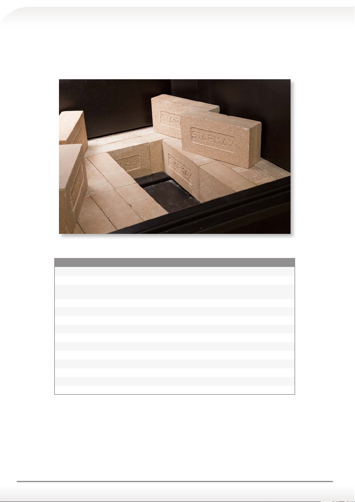
1.2 COMBUSTION CHAMBER
The combustion chamber base of the Thermo Fireplace CARINCI is made entirely of fire resistant bricks with a refractoriness of 1620°C with high efficiency suitable for cooking oven food, vertically positioned in order to arrange a uniform
base of a 60 mm thickness.
TECHNICAL SPECIFICATIONS OF STARMAX BRICKS PRODUCT0
PRODUCT: Dense refractory brick with a siliceous matrix
TYPICAL USES: civil uses, general purposes, construction of household ovens, fireplaces, heaters, pizza ovens.
USI INDUSTRIALI: parts of equipment with operating temperatures below 1150°C, dust chambers and control
of fumes.
TECHNICAL DATA
Refractoriness: 26 CS / SC
Temperature 1620°C
Apparent porosity: 18-20%
Weight - Volume: 1850-1950 Kg / mc
Compressive strength (cold): 300-350 Kg / mc
Compressive strength (hot): 1210°C Ta-Tr
Temporary expansion: +0.65% (1000°C)
Permanent linear variation: +/- 0.5% (2 h a 1000°C)
Thermal conductivity: (0.94-0.00014Xt) kcal/mh°C
8
Page 9
POSITIONING OF THE THERMO FIREPLACE INSIDE THE ROOM
It is absolutely necessary to do the displacement and unpacking of the Thermo Fireplace with adequate tools and to
verify the compatibility of the internal room where you require to install.
2.1 DISPLACEMENT OF THE THERMO FIREPLACE
When moving and unpacking the Thermo Fireplace you must absolutely:
a) Keep it upright at all times;
b) Never turn it in a horizontal position;
c) If necessary, move it with an inclination towards the rear or side view up to a maximum of 45° in order to avoid that
the chain (positioned inside the door) detaches from the pinion on which rotates, causing the block of the door itself.
d) Do not ever tilt it on the front to avoid breakage of the glass.
2.2 CHECKING THE BEARING PLATE
a) Inspect the capacity of the floor;
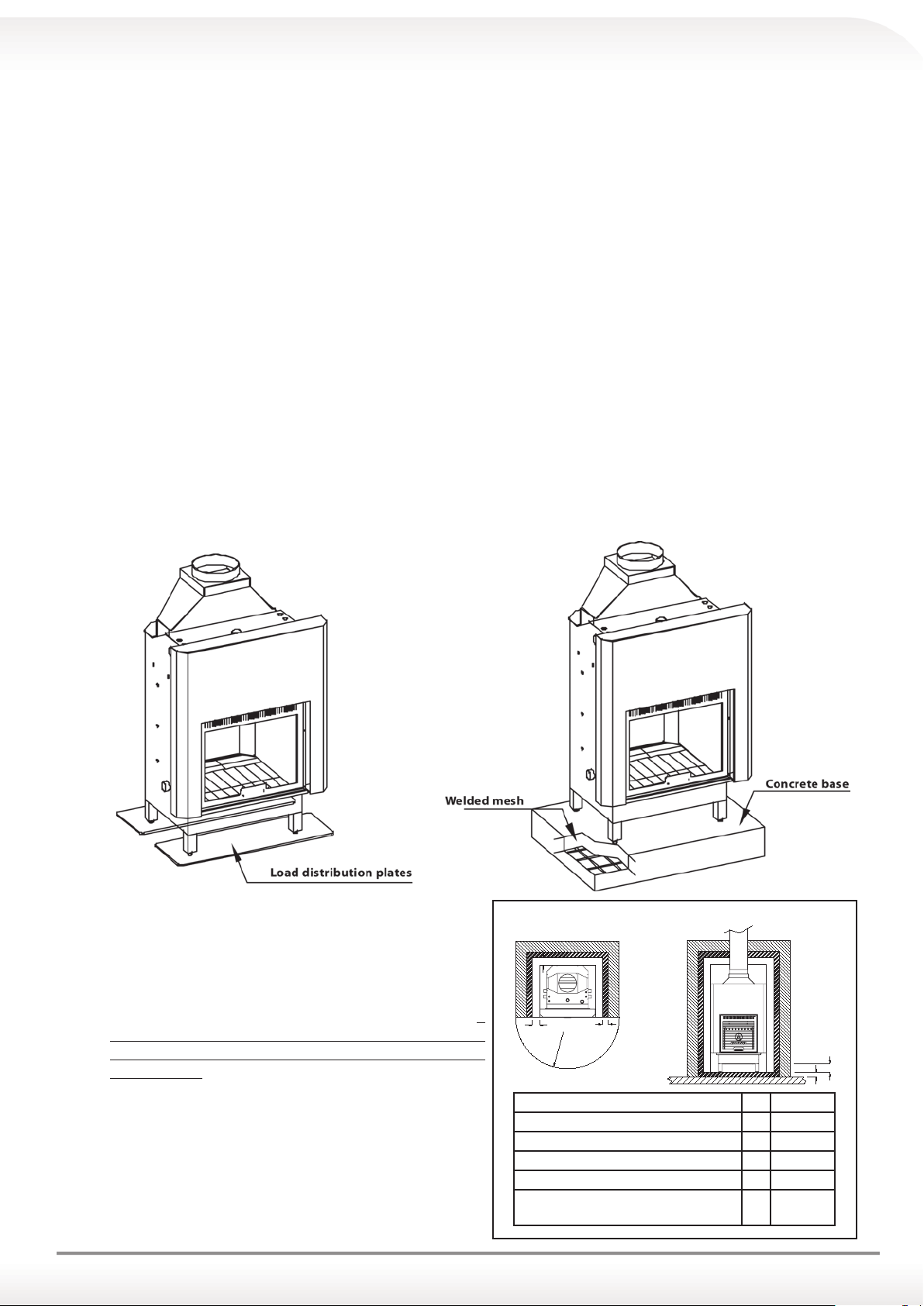
b) In the case of the floor not being suitable to support the weight of the thermo fireplace, it is possible to install steel
plates or a concrete base in order to distribute the weight. (see figure)
Note: for the plates and the concrete base size, make sure to consult a qualified technician.
c) It is recommended to install the thermo fireplace from floor to fire level of about 40/50 cm height to simplify the
use.
d) Form a straight line surface by using the appropriate adjustment screws under the feet of the thermo fireplace.
2.3 INSPECTION OF THE WALLS ADJACENT TO THE
FIREPLACE
a) It is advisable to never install the thermo fireplace along
the walls, leave at least 2 cm space;
b) Never install the thermo fireplace against flammable walls;
c) In case of unavoidable installation near flammable walls, it
is absolutely necessary to insulate the walls using insulat-
ing plates made of Calcium Silicate “PROMASIL 1000” of 40
mm thickness.
d) While installing the covering, it is recommended to leave
a small space of about 0.5 cm for any possible thermal ex-
pansion.
e) Minimum distance from the front of the thermo fireplace
to flammable materials. (see figure)
Distance from flammable materials
B
A
Straight-line distance from flammable side door A 100 mm
Straight-line distance from flammable read door B 100 mm
Insulating material thickness for the side/rear door C 80 mm
Straight-line distance from flammable floor D 150 mm
Insulating material thickness for the floor E 80 mm
Straight-line minimum distance from
flammable material
C
R
R 200 cm
D
E
9
Page 10
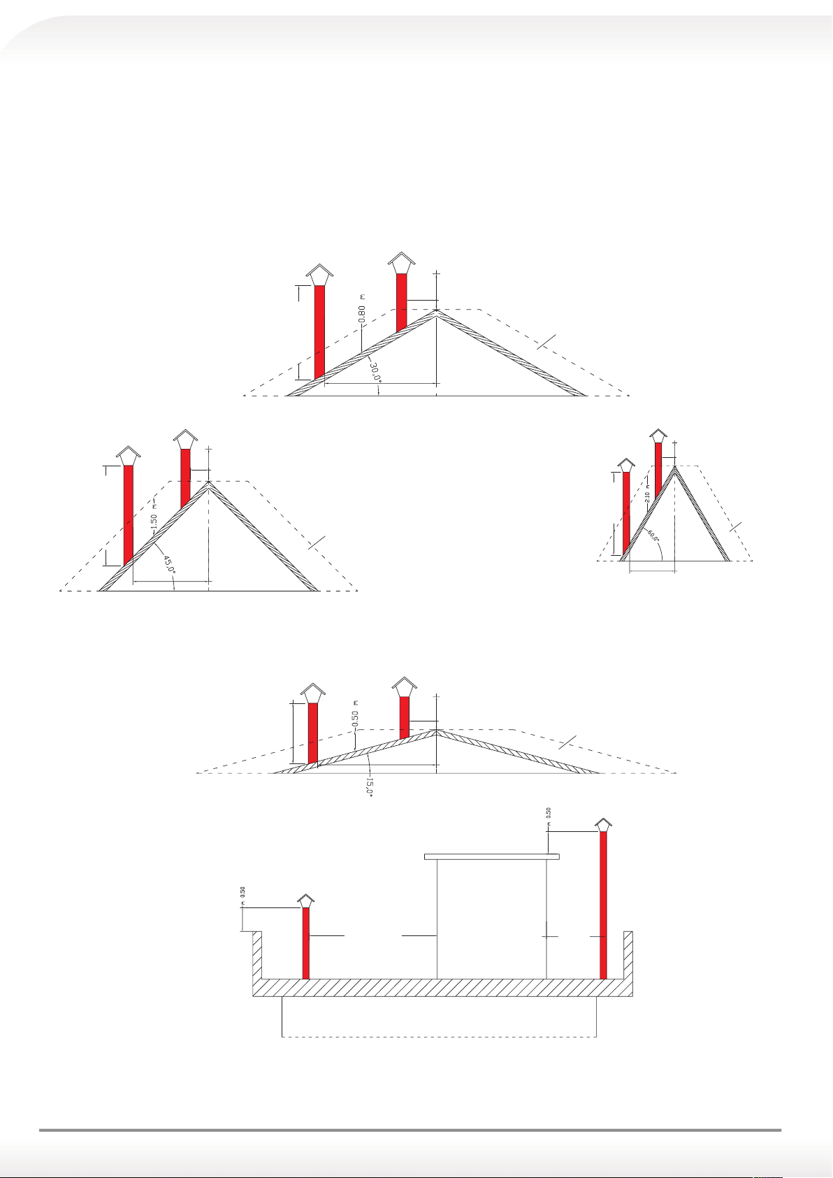
3.0 FLUE (in compliance with Regulation UNI cig 7129/92)
The flue is an important component for the heating system with a wood-burning thermo fireplace. Its function is not
only to evacuate and disperse the fumes, but also to ensure, thanks to an excellent draft, the proper functioning of the
Thermo Fireplace with its natural draft.
0,50 m - over the ridge
distance
≤ 1.30 m
reux area
1.20 m minimum
distance > 1.30 m
c) roof at 30°
0,50 m - over the ridge
distance
≤ 1.50 m
0,50 m - over the ridge
distance ≤ 1.30 m
2 m - minimum
e) roof at 45°
distance > 1.30 m
reux area
1 m - minimum
distance > 5 m
0,50 m - over the ridge
distance ≤ 1.85 m
distance > 1.85 m
b) roof at 15°
TECHNICAL
VOLUME
distance
≤ 5 m
reux area
2.6 m - minimum
reux area
distance > 1.20 m
d) roof at 60°
10
a) at roof
Page 11
3.1 FLUE FUNCTIONS Pag. 13
The functions of the flue are:
a) To function as a fumes exhaust system;
b) To ensure the proper functioning of the thermo fireplace thanks to a good draft.
3.2 FLUE FUNCTIONS
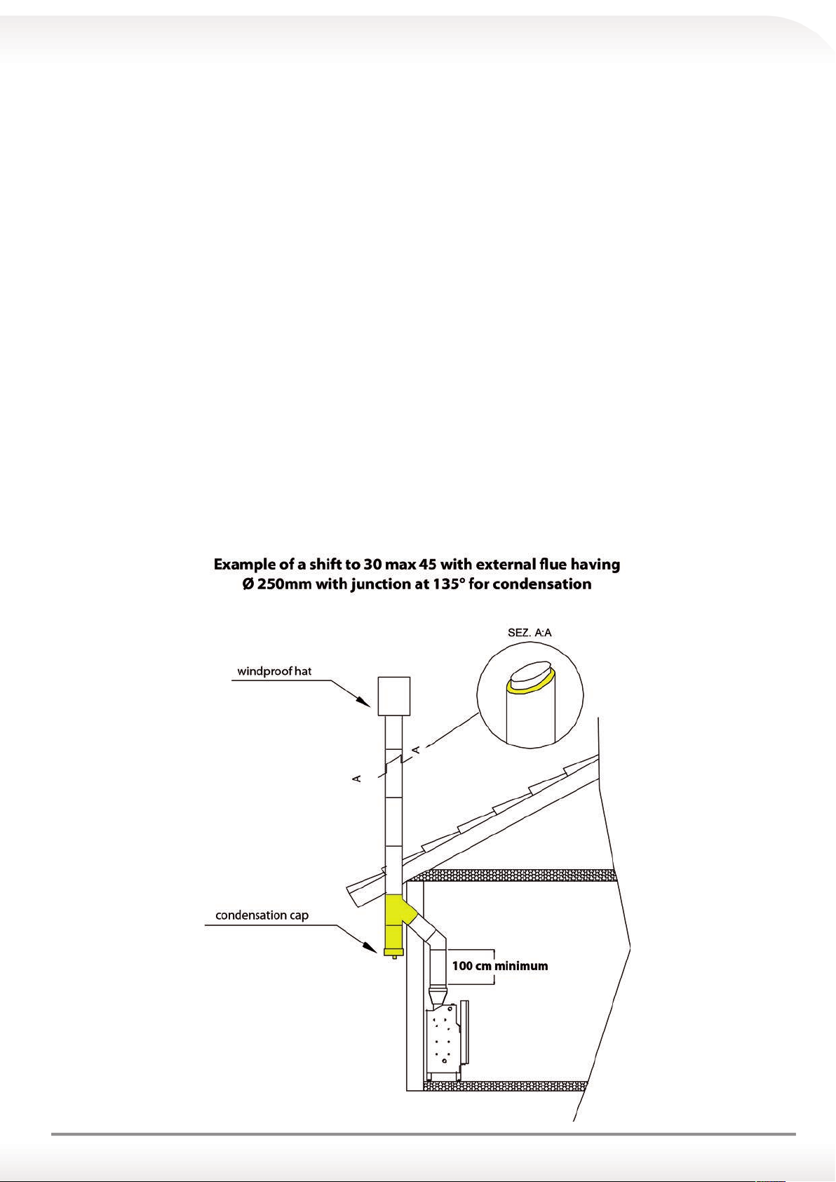
The flue must have the following features:
a) a diameter measuring no less than 250 mm;
b) be partially reduced without compromising the draft that must be minimum 12 + 2 Pa;
c) Must have smooth walls;
d) Must have a uniform internal section, preferably circular;
e) Must be at least 4 metres high;
f) Must be at least 50 cm higher than the peak of the roof;
g) If required, an incline is allowed (but no higher than 45°); for variations of sections or parts, the functioning of the
fumes evacuation system must be inspected with a suitable fluid-dynamic calculating method (UNI 9615);
h) Must have a condensate and solid material drain and collection point;
i) Must have a double wall or single wall with insulation and cavity wall;
j) Any bends connecting to the flue must have inspection points that allow the system to be checked and maintained;
k) Feature a wind-proof chimney at the top end;
l) The point between the flue and walled structure must be hermetically-sealed (see drawing) with a material which is
suitable for high temperatures and thermal expansion;
11
Page 12
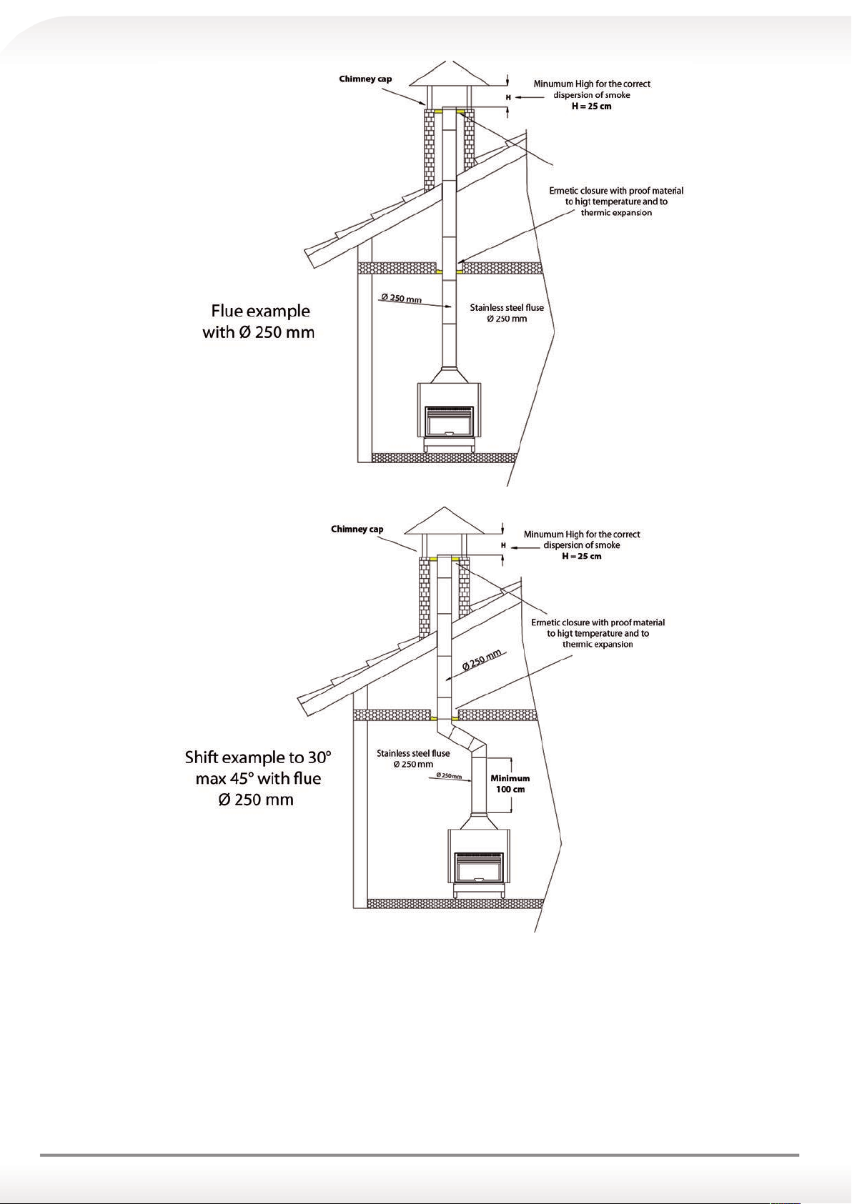
3.3 CHIMNEY STACK
It is necessary to install a chimney stack at the top of the flue to facilitate the dispersion of fumes.
The chimney stack must comply with the following requirements:
a) Have the same diameter of the flue;
b) Be well-isolated;
c) Be located in the highest point;
d) Guarantee the correct dispersion of fumes in any weather conditions (strong wind, rain, etc.);
e) Be easy to remove to facilitate cleaning.
Attention: Use of metal and/or flexible pipes is strictly forbidden.
12
Page 13
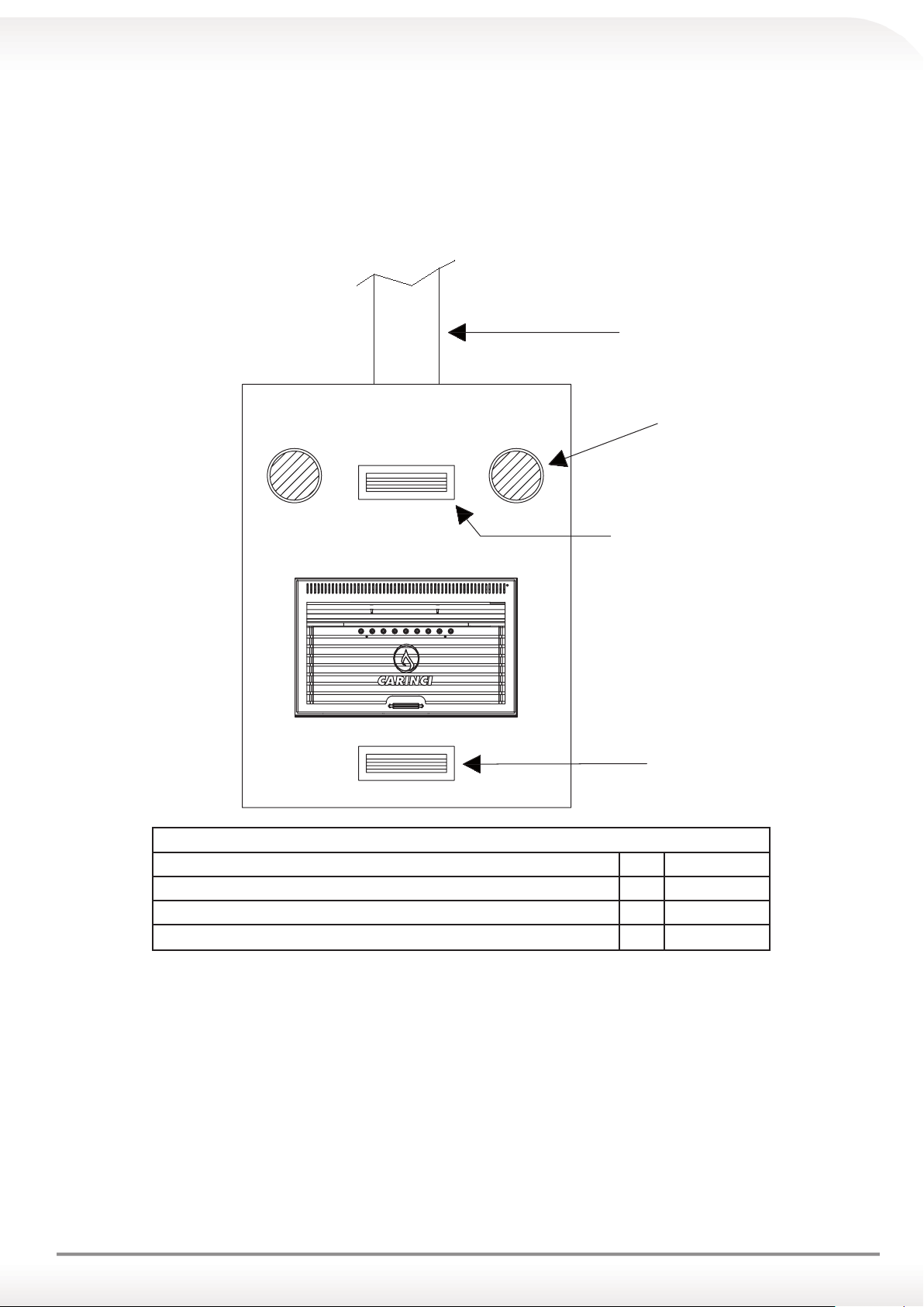
4.0 AIR SCOOP
The thermo fireplace must have the right amount of air to ensure proper combustion. For this reason, it is recommended
to create, in the internal installation area, an external air scoop of adequate size. Air scoop must be calculated based
on the requirement of the internal environment where the thermo fireplace is installed, and must be protected with a grill.
It is recommended not to install other fireplaces, stoves or hoods inside the same room.
If the thermo fireplace is near a staircase to the upper floors, it is necessary to close it off with a hermetic door.
Note: it is strictly forbidden to create the air scoop below thermo fireplace hood, in order to avoid
boiler body cooling.
D
C
B
A
CONVECTIVE AIR INLET/OUTLET MINIMUM SECTIONS
Convective air inlet minimum section A 600 cm
Convective air inlet minimum section B 600 cm
Sections of forced convection air outlet C 100 mm
Test fireplace minimum internal diameter D Ø 200 mm
Note: it is recommended to create air scoops as per drawing, since the grills positioned in this way ensure the passage of air in a natural way through the chamber (hood) where the heat, released from the flue, is radiated inside the
house.
2
2
13
Page 14
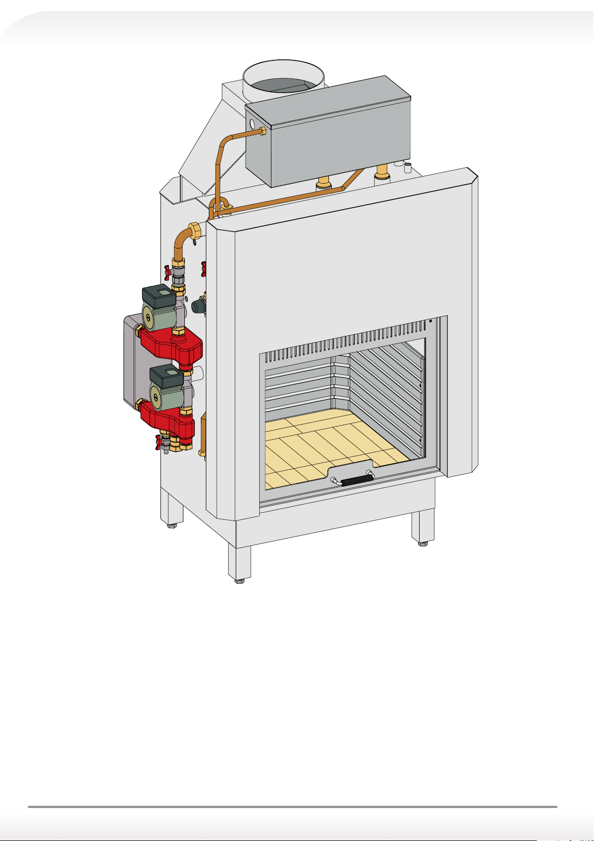
5.0 PRESENTATION OF THE THERMO FIREPLACE CARINCI EVOLUTION SYSTEM
The Thermo Fireplace CARINCI EVOLUTION SYSTEM was designed to permanently eliminate the combination
problem with the gas boiler.
The system is already assembled with the open vent, in compliance with Italian regulations, and can be combined with any
another heat-generator.
This system provides the following advantages:
a) There is no need to position the expansion vessel in the highest point of the house.
b) There is no need to break walls or attics to allow the passage of the piping.
c) Easy installation.
d) Less time required for the installation.
e) Less manpower costs.
f) It can also be installed in an apartment/at inside an apartment complex.
g) The thermo replace works with an open vent (already included) in compliance with the Italian regulation to ensure
maximum safety, while the system is operated in closed circuit with any other heat source.
h) The thermo replace with double circuit CARINCI SYSTEM can also be installed on the ground oor and supply the upper oors.
14
Page 15
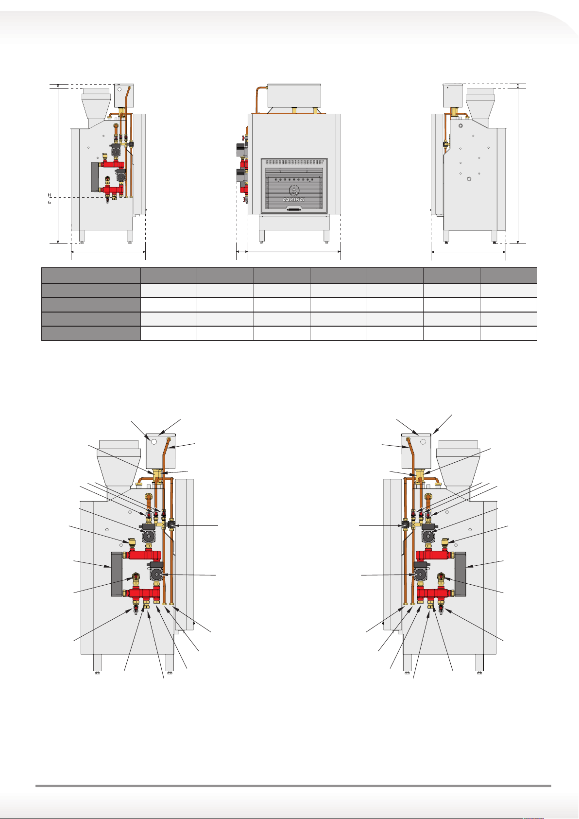
5.1 TECHNICAL SPECIFICATIONS AND DIMENSIONS OF THE THERMO FIREPLACE CARINCI EVOLU-
DD
expansion tank
expansion tank
TION SYSTEM
B
A
EC
Model A B C D E G H
SYSTEM 150 71 142 (± 2) 8 9.5 (± 2) 77 40 (± 2) 43 (± 2)
SYSTEM 200 71 148 (± 2) 8 4 (± 2) 88 40 (± 2) 43 (± 2)
SYSTEM 250 71 153 (± 2) 8 0.5 (± 2) 99 40 (± 2) 43 (± 2)
SYSTEM 300 71 157 (± 2) 8 4 (± 2) 110 40 (± 2) 43 (± 2)
Measurements are expressed in cm
5.2 KIT SYSTEM POSITION ON THE THERMO FIREPLACE CARINCI EVOLUTION
KIT SYSTEM left side KIT SYSTEM right side
output overow pipe
Safety pipe
thermo replace
in stainless steel
load pipe
expansion tank
output overow pipe
load pipe
expansion tank
in stainless steel
A
B
Safety pipe
thermo replace
ball
valves
circulator n. 1 circulator n. 1
vent
valve
Brazed plate
heat
exchanger
ball
valve
drain
cock
non-return
valve
Heating system return Heating system return
load pipe
thermo replace
thermostatic
domestic
water
circulator n. 2
Domestic hot water
outlet mixed
Cold water inlet Cold water inlet
Heating system ow Heating system ow
Domestic hot water
outlet mixed
load pipe
thermo replace
thermostatic
domestic
water
circulator n. 2
non-return
valve
ball
valves
vent
valve
Brazed plate
heat
exchanger
ball
valve
drain
cock
N.B. KIT SYSTEM can be installed on both the right and left side of the thermo fireplace (looking at
the thermo fireplace frontally).
15
Page 16
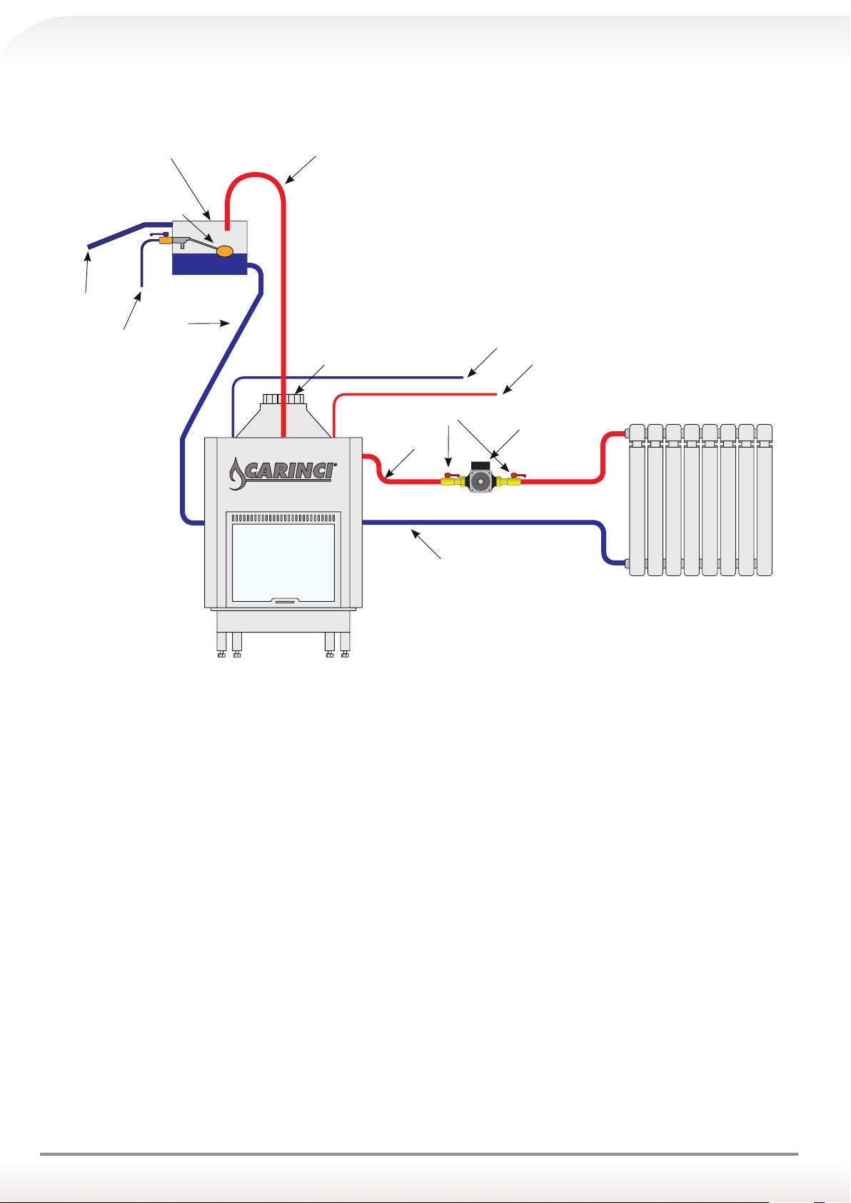
6.0 INSTALLATION OF THE THERMO FIREPLACE CARINCI EVOLUTION
1
11
6.1 OPEN-VENTED SIMPLE INSTALLATION SCHEME
5
4
2
3
12
6/7
6/7
13
10
8
9
LEGEND:
1. Copper safety pipe minimum diameter 28 mm (if needed, short bended tracts can be used, using only 45° open
curves, always upsloping towards the expansion vessel)
2. Copper load pipe system minimum diameter 28 mm
3. Load pipe expansion tank
4. Copper overflow pipe minimum diameter 28 mm
5. Float with copper sphere
6. Cold water inlet (do not install check valves)
7. Hot sanitary water outlet
8. Heating supply copper pipe of fitting diameter section but not less than 28 mm diameter
9. Heating return copper pipe of appropriate section but not less than 28 mm diameter
10. Circulator (we recommend positioning the circulator not adhering to the thermo fireplace, but in adequate posi-
tion to simplify the coating)
11. Open expansion vessel (must be placed at least one meter higher than the last radiator or fireplace or pipe, and
cannot be installed higher than 12 m from the thermo fireplace). Note: the thermo fireplace cannot be mounted
with a closed vessel or with a pressure greater than 1,2 ate in any way (the thermo fireplace must be filled ex-
clusively with gravity flow from the expansion vessel)
12. Flue inlet diameter 250, cannot be reduced. If needed, short bended tracts can be used, using only 45° or 30°
curves
13. Ball valve full passage
16
Page 17

INSTALLATION INSTRUCTIONS FOR THE THERMO FIREPLACE CARINCI
6.2 EXPANSION VESSEL
The thermo fireplace CARINCI must be installed exclusively with an open vent, in compliance with the Italian regulation, and this open vent must have a capacity proportionate to three times the water expansion volume. Expansion
percentage to 90°C = 3/3,5%. In addition, it is recommended to create an inspection door that allows access to the
expansion vessel for any inspection and/or repair work.
6.3 SANITARY HOT WATER
Inside the thermo fireplace a copper heat exchanger is placed immersed in the primary heating water for the production
of sanitary hot water. In the presence of hard water, we recommend installing an anti-limescale product. It is necessary
to install two TEE with removable plugs in the input and output of the coil for the possible chemical washing.
N.B. It is compulsory to install a mixer valve near the outlet of the sanitary hot water to prevent
water from coming out of the taps too hot and burning the user(s).
The thermo fireplace CARINCI SYSTEM and the CARINCI COMBINED are standard equipped with a thermostatic
mixer, adjustable with a knob, at the hot water output. Turning the knob to the right ( - ) the temperature can be lowered
(min 35 ° C) , while turning to the left ( + ) the temperature can be risen (max 60 ° C approximately).
6.4 PROCESS CONTROL AND SHUT-OFF VALVE
Install a ball valve on the chimney stack's sanitary cold water input pipe. This valve:
1. regulates the rate of water flow to the sanitary exchanger;
2. closes the sanitary water circuit of the thermo fireplace.
N.B.: It is strictly forbidden to install a shut-off valve on the sanitary hot water outlet pipe of the
thermo fireplace. Furthermore, in the case where the sanitary exchanger is not used it should be
left open without any kind of cap (some insulating tape can be applied) in order to prevent breakage.
6.5 CHECK VALVE
The check valve should never be installed in the sanitary cold water inlet of the thermo fireplace.
6.6 FILLING THE THERMO FIREPLACE
Thermo fireplace must only be filled with gravity flow of the water contained in the expansion vessel.
6.7 EXTRACTOR FAN
If the thermo fireplace is installed in the kitchen, where an extractor hood is also installed, be careful when it is activated, since it could absorb all the inner oxygen causing a malfunction of thermo fireplace, even in the presence of any
air scoop.
6.8 WATER HAMMER
On some systems, with the installation of the thermo fireplace, it is possible that, after a sudden closing of a tap (single
lever) a noise or vibration coming from the inside can be heard.
This may happen due to:
• Excessive pressure on the pipe;
• Length of the pipe;
• The quantity of water in the sanitary circuit.
If this occurs, install a suitable protection system (anti-shock) to dampen/cushion the noise or vibration.
Therefore, it is advisable also to open the window.
6.9 INSTALLATION INSTRUCTIONS FOR THE THERMO FIREPLACE CARINCI SYSTEM OR IDROKIT
Thermo fireplace CARINCI SYSTEM or IDROKIT is composed of two circuits:
A. primary circuit, which is the thermo fireplace itself, working open vented;
B. secondary circuit, which is the kit SYSTEM (or IDROKIT) working in closed circuit.
The secondary circuit should be connected to the existing heating system for which it is mandatory:
1. To install a filling unit comprised of a pressure gauge, non-return valve and shut-off valve in order to ensure the auto-
matic filling of the system and to maintain the right pressure within radiator circuit stable;
17
Page 18
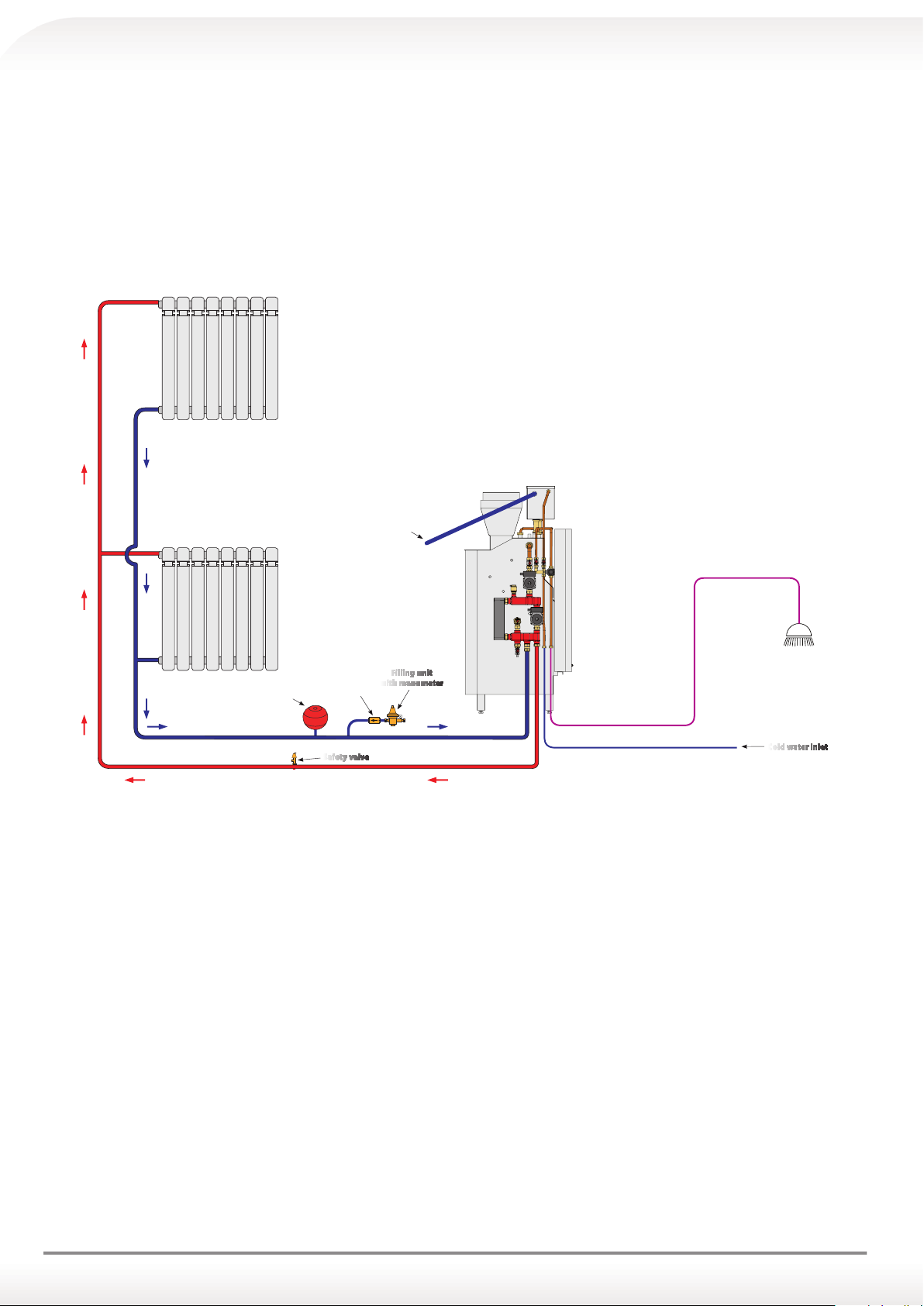
2. To install an expansion vessel (suitable for closed circuit) with an appropriate capacity and a safety discharge valve
with an adequate pressure in order to avoid pressure increase inside the circuit itself (see figure A);
3. It is necessary to do a full cleaning of the heating system before the installation of thermo fireplace CARINCI SYSTEM
or IDROKIT;
4. To install a Y-shaped filter on the heating return in order to avoid blockage of the exchanger due to impurity deposits
in the existing system, especially if the system is made of iron with cast iron radiators.
5. It is necessary to clean out the air inside the radiator circuit through the general blow hole located near the plate heat
exchanger, and through the manual small blow holes located on the radiators.
6. Before operating the system, make sure there is no more air inside the circuits, both the primary and the secondary.
SIMPLE INSTALLATION DIAGRAM CARINCI MIX (figure A)
output overflow pipe
Domestic hot
water outlet mixed
Cold water inlet
diaphragm expansion
vessel
Heating system return
non-return
valve
Safety valve
Filling unit
with manometer
5
4
6
3
7
2
8
1
9
0
1
0
Heating system ow
6.10 INSTALLATION COMBINED WITH A GAS BOILER
(Equipped with expansion vessel and safety discharge valve) [For SYSTEM and IDROKIT].
If the existing heating system has a gas boiler tted with expansion vessel and safety discharge valve, it is possible to avoid
the further installation of the expansion vessel and safety discharge valve (see gure B), upon a check of the expansion vessel capacity.
6.11 INSTALLATION COMBINED WITH A GAS BOILER
(Excluding expansion vessel and safety discharge valve) [for SYSTEM and IDROKIT].
In case the system is equipped with a gas, diesel, wood boiler but not with expansion vessel (suitable for a
closed circuit) and safety discharge valve, it is mandatory the installation of an expansion vessel with adequate capacity and a safety discharge valve with adequate pressure.
6.12 RADIATOR SYSTEM FILLING (For SYSTEM and IDROKIT)
The secondary circuit should be connected to the existing heating system for which it is mandatory to install a lling unit
composed of pressure gauge, non-return valve and shut-o valve in order to ensure the automatic lling of the system and
to maintain the right pressure within radiator circuit stable. For the manual lling of the radiator system it is also possible to
use the gas boiler lling tap (if equipped). Check periodically the pressure of the system through the boiler pressure gauge
and replenish if needed.
18
Page 19
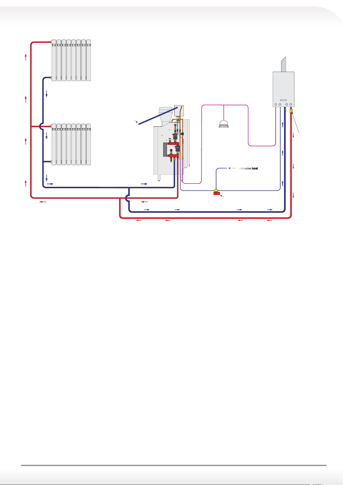
INSTALLATION DIAGRAM: CARINCI SYSTEM COMBINED WITH A GAS BOILER (figure B)
BOILER
output overflow pipe
Domestic hot
water outlet mixed
Cold water inlet
Heating system return
non-return
valve
Heating system ow
motorized valve
boiler return
boiler ow
19
Page 20
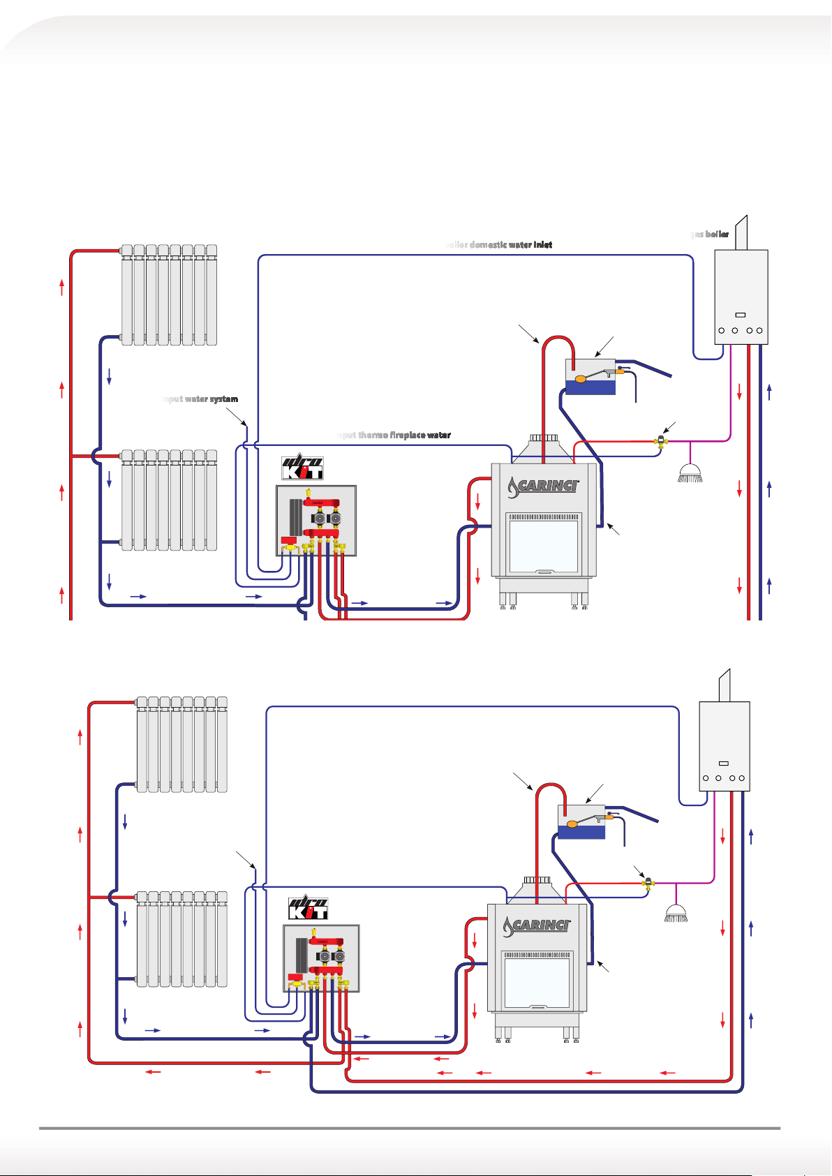
6.14 DOUBLE CIRCUIT INSTALLATION WITH CARINCI IDROKIT
- Thermo fireplace working with open vessel
- System working with closed circuit
This type of system should be set up when boiler, radiators and pipes are higher than the thermo replace open expansion
vessel.
In this case the thermo replace works normally with open vessel, radiators, boiler secondary piping work in closed circuit
through the heat exchanger with reed valve which divides the two circuits, primary and secondary.
INSTALLATION DIAGRAM WITH IDROKIT 5 CS
Input water system
Heating system return
Input thermo fireplace water
8
CS
R - IMP
M - TC
R - TC
M - IMP
thermo replace
return
boiler domestic water inlet
Safety pipe
open expansion vessel
thermostatic
domestic water
water outlet mixed
Load pipe
gas boiler
Domestic hot
Ingresso acqua
impianto idrico
Ritorno Impianto
Mandata Impianto
INSTALLATION DIAGRAM WITH IDROKIT 8 CS
Ingresso acqua sanitaria caldaia
Tubo di sicurezza
Ingresso acqua Termocamino
8
CS
R - IMP
M - TC
R - TC
M - IMP
Ritorno
Termocamino
Mandata
Termocamino
Mandata Caldaia
Vaso d'espansione
aperto
Miscelatore
Termostatico
Calda Sanitaria
Tubo di carico
CALDAIA a gas
Uscita Acqua
Miscelata
20
Page 21
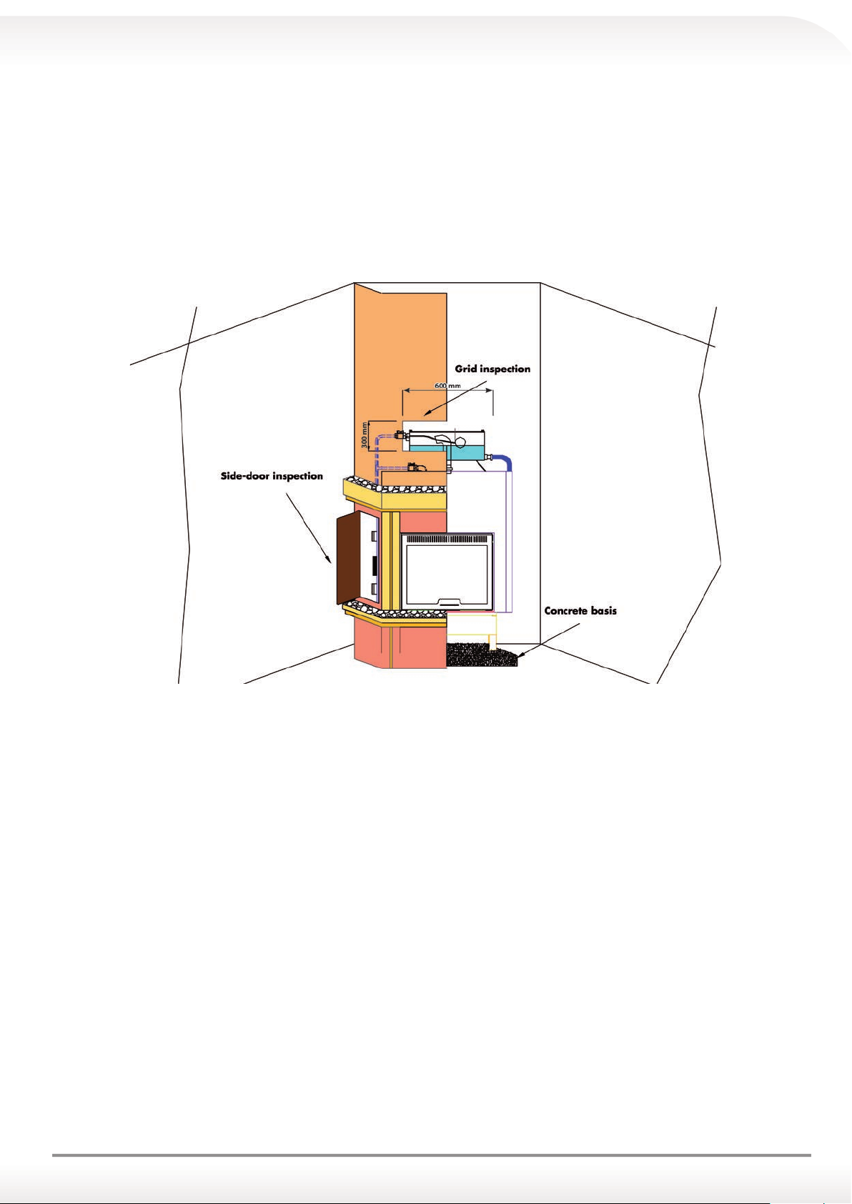
6.15 INSTALLING INSPECTION GRILL ON THE HOOD
It is mandatory to install an inspection grill on the hood; this grill can be used to access the expansion vessel for any
inspection or repair work.
6.16 INSPECTION SIDE DOOR INSTALLATION (for Thermo fireplace CARINCI SYSTEM)
It is necessary to leave, on the side where the kit system is installed, an inspection door for any maintenance of the
same kit components.
N.B.: It is mandatory to create an air scoop in the lower part of the covering in order to guarantee
the right amount of combustive air to the combustion chamber through the secondary air input
and the tertiary air input.
6.17 PIPE OVERFLOW OF EXPANSION VESSEL
a) Put it outside of the wall, always sloping down towards the outside, at such a height which, in case of a spill of
boiling water, will not cause damage to people and/or things.
b) It is absolutely forbidden to place the overflow pipe exit in the external wall at a man-height.
c) It must be channelled into a waste water catch basin, whose end must be easily inspectable in case of any small loss
due to breakage of the float.
d) Use a pipe of suitable section (not less than Ø 28 mm) to allow the correct evacuation of water in excess from the
expansion vessel.
e) Use metal, copper, or similar material for the pipes, as long as they are able to bear the excessive temperature caused
by possible boiling.
f) Fit the exit of the pipe with a small anti insects net, which must be large meshed and must ensure the eventual pas-
sage of excess water caused by the possible boiling.
6.18 ADVICE FOR THE INSTALLER
a) Check the water level in the expansion vessel.
b) The level recommended is approximately 8/10 cm of water.
c) In case that this level does not match, adjust the float bending the rod slightly.
6.19 ADVICE FOR THE USER
a) Periodically check the presence of water in the expansion vessel.
b) In the case that there is no water inside, do not switch on the thermo fireplace and call your technician or service
centre.
21
Page 22
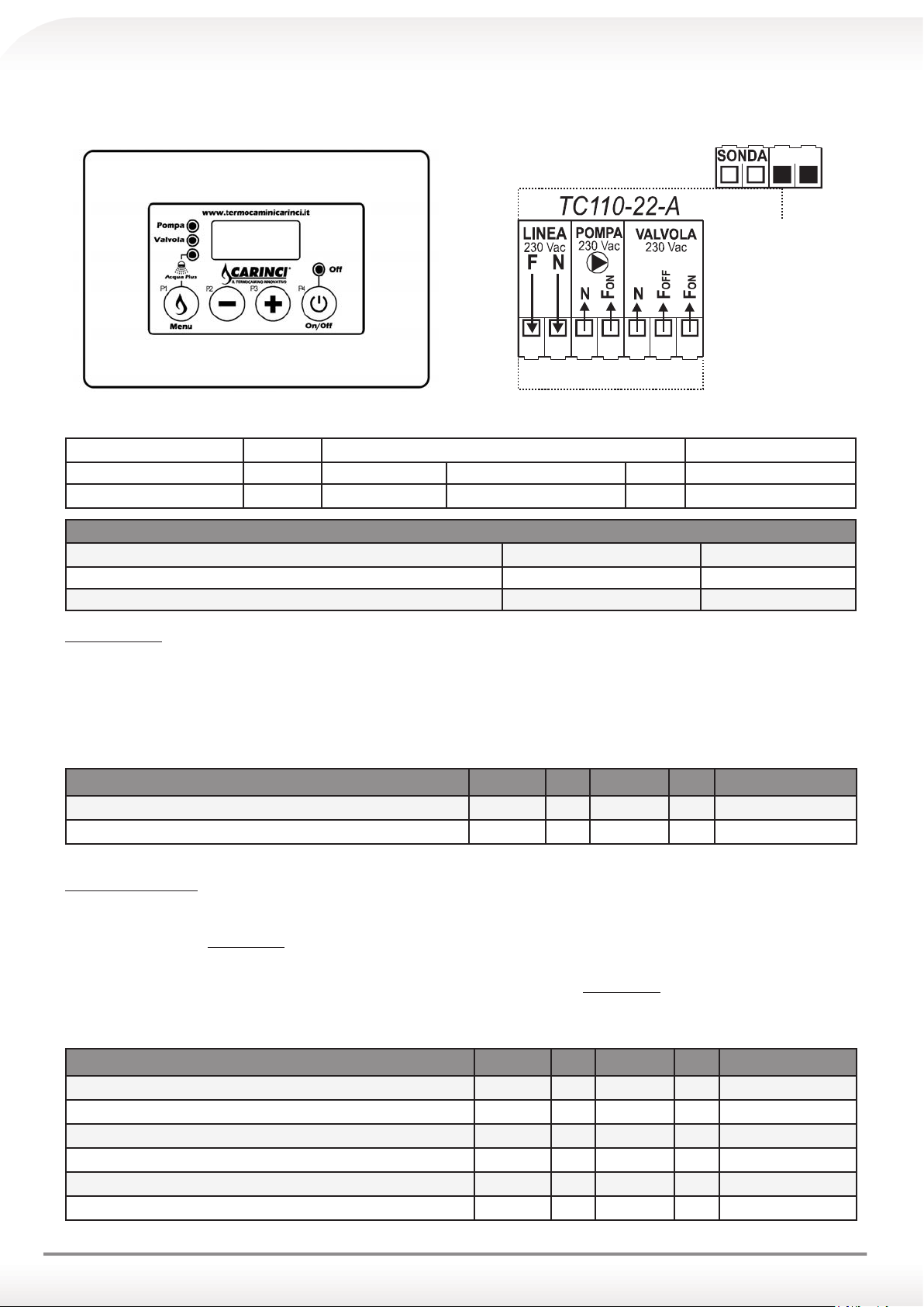
6.20 ELECTRONIC CONTROL UNIT OF THE THERMO FIREPLACE CARINCI
Control unit instruction manual mod. TC 110-22-A
1234567
Fig. 1 External appearance and power linkage diagram
INPUTS PROBE Thermo fireplace probe : Temperature range 0 - 100 ° C
OUTPUTS PUMP System pump 230 Vac power supply clips 3(N) - 4 (Fon)
VALVE valve 230 Vac power supply Clips 5(N) - 6 (F
OFF) - 7 (FON)
RECOMMENDED VALUES SETTING ON THERMOSTAT
Min Max
Thermostat HEATING PUMP 53 °C 57 °C
Thermostat SANITARY WATER VALVE 40 °C 45 °C
MAIN Menu
By pressing and holding for about 5 secs. P1 button (MENU) it is possible to scroll set thermostats values signalled by the flashing of the respective
LED associated.
For editing:
Navigate to the value of the thermostat to modify;
Use the buttons P3 (+) and P2 (-) to increase/decrease the value;
To save changes, wait about 5 secs. or scroll through the values with the P1 button (MENU)
MAIN Menu Parameters Symbol Min Factory Max Installed values
Thermostat PUMP 1 [°C]
Thermostat VALVE [°C]
A 07
A 05
20
20
50
42
85
85
INSTALLER Menu
The access to this menu is LIMITED TO TECHNICIANS OR TRAINED PERSONNEL, since some parameters, if modified, can make the product no
longer suitable for the application in use.
To access the menu, press simultaneously P1(MENU) P4 (ON/OFF) buttons for about 5 seconds;
To scroll through the parameter labels use P3 (+) and P2 (-) buttons;
To display the parameter value, press P1(MENU) button;
To change the value press P3 (+) and P2 (-) buttons and P1(MENU) P4 (ON/OFF) buttons simultaneously for about 5 seconds;
To redisplay the list of parameters and store press P1(MENU) button;
To exit and save wait approximately 5 seconds.
INSTALLER Menu Parameters Symbol Min Factory Max Installed values
Activation thermostat ALARM function [°C]
SAFETY thermostat [°C]
ANTIFREEZE Activation thermostat [ICE] [°C]
Hysteresis thermostat PUMP [°C]
ANTI-LOCK timer [h]
ANTI LOCK pump activation time [sec]
22
A 01
A 02
A 03
A 04
t 01
t 02
85
20
90
85
4
1
1
0
6
2
168
20
99
90
8
5
999
99
Page 23

FUNCTIONALITIESS
1. Start-up/Shut down:
• Start-up/shut down of the control unit can be carried out pressing and holding the P4 (ON/OFF) button;
• The OFF state is indicated by the OFF led.
2. ALARM function;
If the temperature detected by the PROBE exceeds the Alarm thermostat A01 value
• The system activates the audible and visual signalling;
• SILENCE function: the acoustic signal can be turned off for 5 min by pressing any button;
• After this amount of time has passed, if the alarm condition persists, the acoustic signal is activated again.
3. ANTI-FREEZE function:
If the temperature detected by the PROBE falls below the value of the A03 anti-freeze thermostat
• PUMP 1 and PUMP 2 outputs will be activated
• The display will show ICE
4. STANDBY function:
In case of OFF device or in conditions of ALARM or FREEZE
• The device automatically switches to the ON state.
5. PUMP ANTI-LOCK Function:
In case of inactivity of the circulator for a time greater than the anti-lock timer T01 (one week)
• PUMP output will be activated for T02 seconds.
• The display will show bLP
• This function is also active in STANDBY.
6. Function TEST PUMP 1:
By pressing and holding P2 (-) button
• PUMP output will be activated for as long as the button is pressed;
• The display will show tSt.
7. ACQUAPLUS function
Through the simple click of P1(MENU) button
• PUMP output will be deactivated till the SAFETY (A02) temperature of 85°C is reached, after reaching this temperature PUMP output will
be activated till reaching the temperature of 80°C;
• To deactivate the ACQUAPLUS function press the P1(MENU) button again.
REPORTS OF FAILURE OR ALARMS
The control unit sends fault reports to the probe with the following records:
Lo: indicates an off-scale down (temperature below 0°C): Probe interrupted
Hi: indicates an off-scale upward (temperature above 100°C): Probe in short-circuit
TECHNICAL SPECIFICATIONS
Power supply 230 Vac ± 10% ~ 50 Hz; Safety fuse T3,15 A
Power Consumption 2VA~
Temperature probe In silicone cable/pvc; Operating Temperature: -50°C/130°C; Limits of measurement: 0 - 99°C Precision: ± 1 °C
Outputs
Mechanical dimensions Built-in heat regulator: 120 x 80 x 50 [mm]
Applied regulations:
EN 60730-1 50081-1
EN 60730-1
A1 50081-2
PUMP1/PUMP2/VALVE output: 230 Vac power supplied max flow rate 5A 250 Vac
TiEmme elettronica
06055 Marsciano (PG) Italy
tel/fax +39.075.874.3905
www.tiemmeelettronica.it - [email protected]
23
Page 24
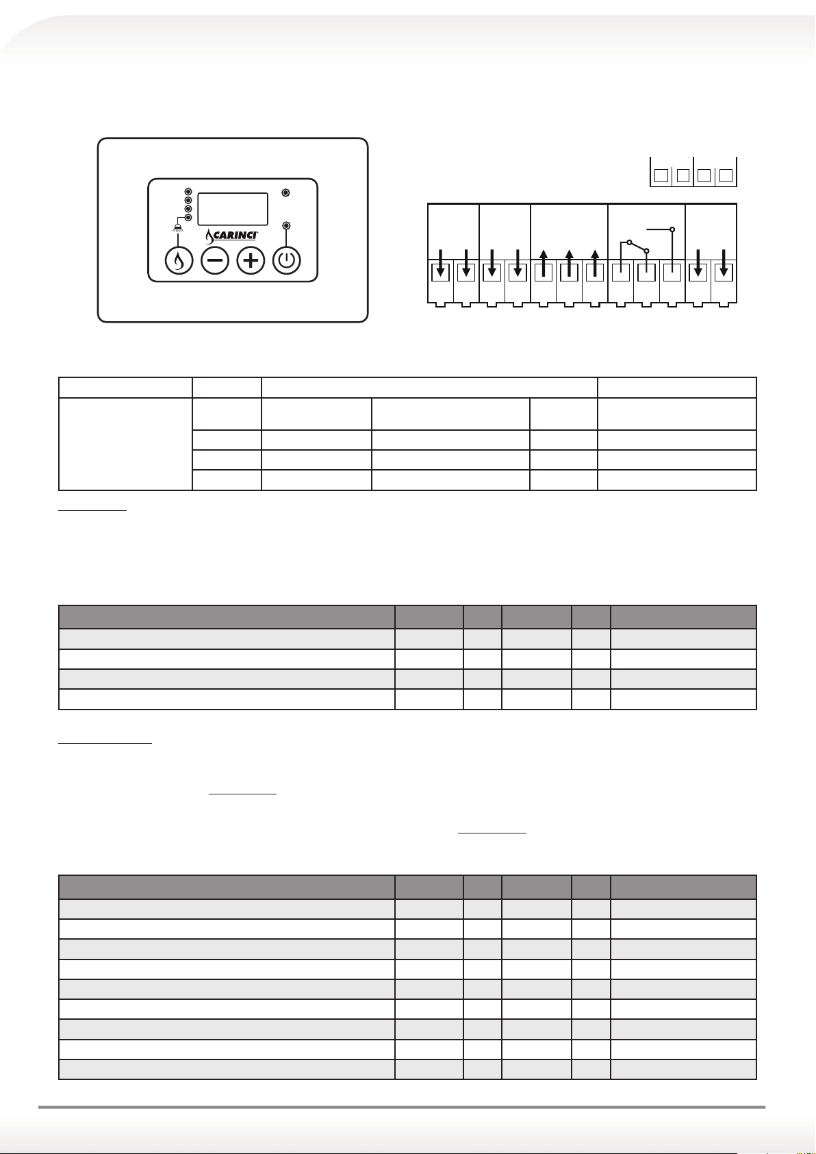
6.21 ELECTRONIC CONTROL UNIT OF THE THERMO FIREPLACE CARINCI SYSTEM AND CARINCI MIX
Control unit instruction manual mod. TC 110-22B-31
SONDAFLUX
Pompa 2
Valvola
Acqua
Plus
www.termocaminicarinci.it
IL TERMOCAMINO INNOVATIVO
Aux
Off
LINEA
230 Vac
FNFFon
POMPA
230 Vac
VALVOL A
230 Vac
123456 7
AUX
8910
POMPA 2
230 Vac
FFonNFo Fon
11 12
Pompa 1
Fig. 1 External appearance and power linkage diagram
INPUTS PROBE
PUMP 1
OUTPUTS
PUMP 2
VALVE
AUX
Thermo fireplace probe : Temperature range 0 - 100 ° C
Thermo fireplace
Primary Pump
230 Vac power supply Clips 3(N) - 4 (Fon)
System Pump 230 Vac power supply Clips 11(N) - 4 (Foff)
valve 230 Vac power supply Clips 5(N) - 6 (F
OFF) - 7 (FON)
Boiler Enabling Free contacts exchange clips 8(COM) - 6 (NC) - 7 (NO)
MAIN Menu
By pressing and holding for about 5 secs P1 button (MENU) it is possible to scroll set thermostats values signalled by the flashing of the respective
LED associated.
For editing:
• Navigate to the value of the thermostat to modify;
• Use the buttons P3 (+) and P2 (-) to increase/decrease the value;
• To save changes wait about 5 secs. or scroll through the values with the P1 button (MENU)
MAIN Menu Parameters Symbol Min Factory Max Installed values
Thermostat PUMP 1 [°C]
Thermostat PUMP 2 [°C]
Thermostat VALVE [°C]
Thermostat AUX [°C]
A 07
A 04
A 05
A 06
20
20
20
20
50
50
42
50
85
85
85
85
INSTALLER Menu
The access to this menu is LIMITED TO TECHNICIANS OR TRAINED PERSONNEL, since some parameters, if modified, can
make the product not anymore suitable for the application in use.
• To access the menu, press simultaneously P1(MENU) P4 (ON/OFF) buttons for about 5 seconds;
• To scroll through the parameter labels use P3 (+) and P2 (-) buttons;
• To display the parameter value, press P1(MENU) button;
• To change the value press P3 (+) and P2 (-) buttons and P1(MENU) button simultaneously;
• To redisplay the list of parameters and store press P1(MENU) button;
• To exit and save wait approximately 5 seconds.
INSTALLER Menu Parameters Symbol Min Factory Max Installed values
Activation thermostat ALARM function [°C]
SAFETY thermostat [°C]
ANTIFREEZE Activation thermostat [ICE] [°C]
Hysteresis thermostat PUMP 1 [°C]
Hysteresis thermostat PUMP 2 [°C]
Hysteresis thermostat VALVE [°C]
Hysteresis thermostat AUX [°C]
ANTI-LOCK timer [h]
ANTI LOCK pump activation time [sec]
A 01
A 02
A 03
i 07
i 04
i 05
i 06
t 01
t 02
85
20
90
85
4
1
1
1
1
1
0
6
2
2
2
2
168
20
99
90
8
20
20
20
20
255
99
24
Page 25
FUNCTIONALITIESS
1. Start-up/Shut down:
• Start-up/shut down of the control unit can be carried out pressing and holding the P4 (ON/OFF) button;
• The OFF state is indicated by the OFF led.
2. ALARM function;
If the temperature detected by the PROBE exceeds the Alarm thermostat A01 value
• The system activates the audible and visual signalling;
• SILENCE function: the acoustic signal can be turned off for 5 min by pressing any button;
• After this amount of time has passed, if the alarm condition persists, the acoustic signal is activated again.
3. ANTI-FREEZE function:
If the temperature detected by the PROBE falls below the value of the A03 anti-freeze thermostat
• PUMP 1 and PUMP 2 outputs will be activated
• The display will show ICE
4. STANDBY function:
In case of OFF device or in conditions of ALARM or FREEZE
• The device automatically switches to the ON state.
5. PUMP ANTI-LOCK function [PUMP 1 and PUMP 2]:
In case of inactivity of the circulator for a time greater than the anti-lock timer T01 (one week)
• PUMP output will be activated for T02 seconds.
• The display will show bLP
• This function is also active in STANDBY.
6. Function TEST PUMP 1:
By pressing and holding P2 (-) button
• PUMP output will be activated for as long as the button is pressed;
• The display will show tSt.
7. Function TEST PUMP 2:
By pressing and holding P3 (+) button
• PUMP output will be activated for as long as the button is pressed;
• The display will show tSt.
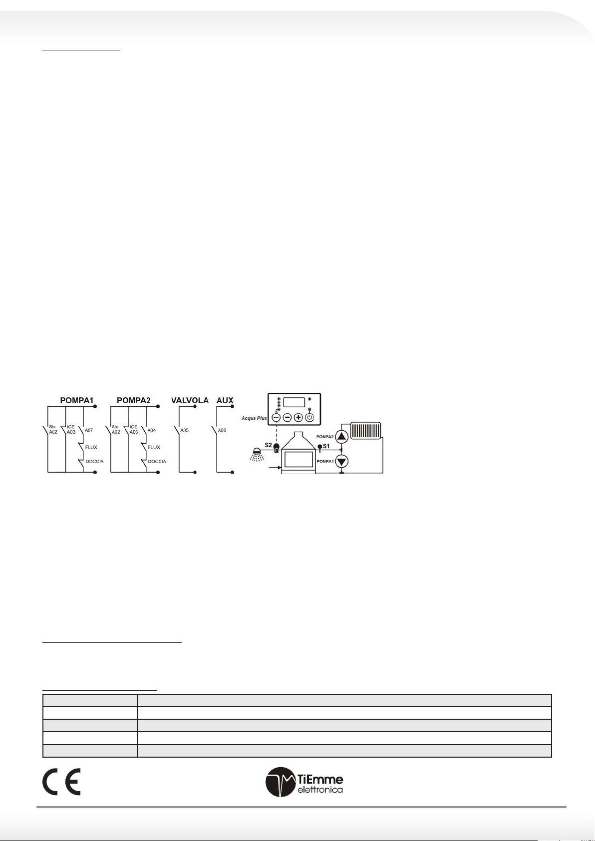
8. OUTPUT function:
9. ACQUAPLUS function
Through the simple click of P1(MENU) button
• PUMP output will be deactivated until the SAFETY (A02) temperature of 85°C is reached, after reaching this temperature PUMP output
will be activated until reaching the temperature of 80°C;
• To deactivate the ACQUAPLUS function press the P1(MENU) button again.
10. FLOWMETER function
The closure of the input of the FLOWMETER determines:
• The deactivation of PUMP 1 and PUMP 2 outputs.
• The closure of the FLOWMETER can be seen on the display with the dash at the top right and led blinking PUMP 1 and PUMP 2 if acti-
vated.
• To deactivate the ACQUAPLUS function press the P1(MENU) button again.
11. SAFETY function
If the temperature exceeds the thermostat SAFETY A02 (default 85°C) activation of the outputs PUMP 1 and PUMP 2 will be forced. If the temperature drops to 80°C the SECURITY function will be switched off.
REPORTS OF FAILURE OR ALARMS
The control unit sends fault reports to the probe with the following records:
Lo: indicates an off-scale down (temperature below 0°C): Probe interrupted
Hi: indicates an off-scale upward (temperature above 100°C): Probe in short-circuit
TECHNICAL SPECIFICATIONS
Power supply 230 Vac ± 10% ~ 50 Hz; Safety fuse T3,15 A
Power Consumption 2VA~
Temperature probe In silicone cable/pvc; Operating Temperature: -50°C/130°C; Limits of measurement: 0 - 99°C Precision: ± 1 °C
Outputs
Mechanical dimensions Built-in heat regulator: 120 x 80 x 50 [mm]
Applied regulations:
EN 60730-1 50081-1
EN 60730-1
A1 50081-2
PUMP1/PUMP2/VALVE output: 230 Vac power supplied max flow rate 5A 250 Vac
TiEmme elettronica
06055 Marsciano (PG) Italy
tel/fax +39.075.874.3905
www.tiemmeelettronica.it - [email protected]
25
Page 26
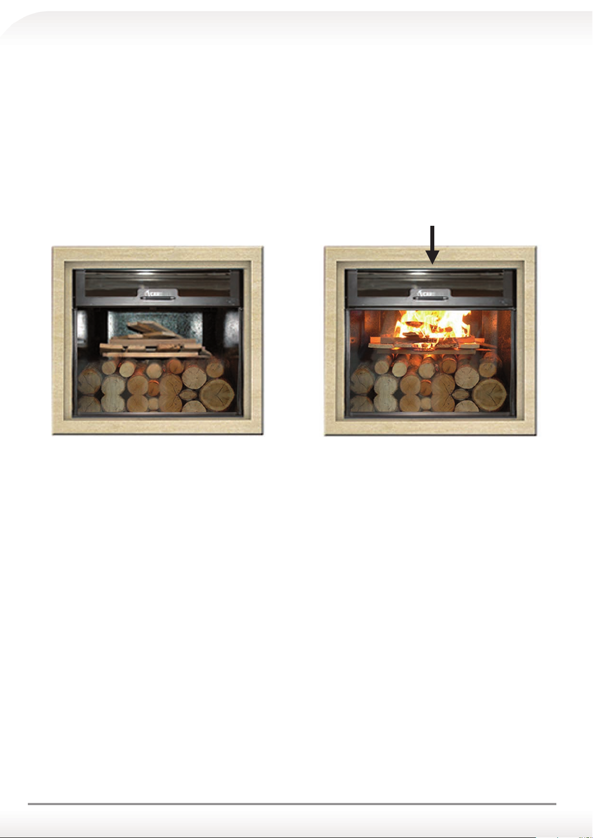
7.0 FIRST START-UP WITH WOOD BURNING OF THERMO FIREPLACE CARINCI
a) Put the switch in the ON position of the digital control unit CARINCI ;
b) Ensure that the inspection plate, at the bottom of the combustion chamber, is closed;
c) For everyday use, it is recommended, for the first start-up of the day, to place 20 to 30 kg of dry wood inside the Ther-
mo fireplace, placing the large wood on the bottom, then the smaller one in the middle and the bundles above, trig-
gering fire to the bundles, burning the wood initially upwards and then spread throughout the combustion chamber;
d) It is recommended, for the first start-up of the day, to keep the door of the thermo fireplace open to a height of about
5/6 cm from the base for about 15 minutes to facilitate the initial combustion. Doing it this way, the time needed for
the condensation in the combustion chamber will be shortened, and the formation of excessive encrustation/tar will
be avoided.
e) Once comfort in the environment has been reached, it is possible to let the natural combustion of the load continue,
by simply stoking it, maintaining the comfort temperature.
START-UP FROM ABOVE
7.1 FUEL QUALITY
Wood
For better results, the quality of the fuel is important.
To get a good combustion, and minimize the formation of condensates and smokiness, it is recommended to bring the
temperature of the Thermo fireplace to about 80°C at least once a day and use:
dry wood, with low humidity around 20%. This is obtained with the seasoning of wood outdoors (covered) for at least one
year);
Furthermore, it is recommended to use mostly wood which is solid and not too resinous (for instance: oak, birch, etc.),
which will allow a contained and resistant flame.
26
Page 27

7.2 FUEL DIMENSIONS
The size of the wood affects the efficiency of the thermo fireplace, so
the advice is to use a fuel variety which reflects the following features:
a) The wood positioned at the bottom must have a length between
30 and 45 cm and a perimeter between 20 and 50 cm;
b) The wood positioned in the middle should have a length between 30
and 45 cm and a perimeter between 10 and 20 cm;
c) The bundles must be positioned above the two layers previously
placed and may be formed from a very small piece of wood, small
wooden boards, etc.
The size of the pellets must not be more than 6 mm in diameter.
8.0 ADJUSTMENTS
8.1 CIRCULATOR ADJUSTMENT AND SYSTEM BALANCING
a) The circulator must be proportionate to the size of the system;
b) It is recommended to always make it work at minimum speed and to adjust the inflow of water in the radiators closer
to the collector (through the adjustment screw of the flux valve), in order to avoid the annoyance of dripping and
improve the inflow of water in radiators furthest, thus improving their efficiency;
c) In case the minimum speed is not enough, switch to the average speed, check the radiators performance, and if it is
not sufficient yet, switch to the maximum speed.
1
2
3
8.2 COMBUSTION ADJUSTMENT
Every thermo fireplace CARINCI is equipped with a very simple system for adjusting the combustion which is located in
the upper right side of the door, that, by using a 5 mm hexagonal key (called Allen key), allows the user to adjust the
width of the air throttler rings, in order to have a homogeneous flame throughout the combustion chamber.
The proper combustion is obtained when the flame is neither too powerful nor too weak.
If a proper burning does not take place using the thermo fireplace, it is possible to adjust the air flow in the following way:
a) Insert the hexagonal key (Allen key) into the combustion regulator located on the top right of the door (see figure);
27
Page 28
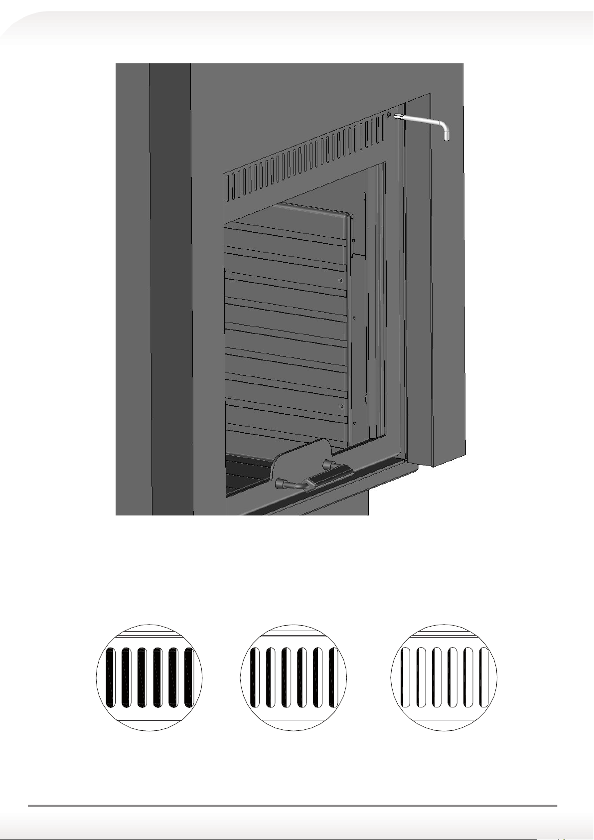
AIR THROTTLER (GLASS SCREEN)
SETTING EXAMPLE
b) If the flame is too powerful, unscrew using the hexagonal key in order to narrow the air throttler rings, decreasing the
inlet air and thus slowing down the combustion;
d) If the flame is too weak, screw using the hexagonal key, in order to widen the air throttler rings, increasing the inlet air
and thus increasing the combustion;
28
low heat
(minimum air passage)
medium heat
(average air passage)
high heat
(maximum air passage)
Page 29
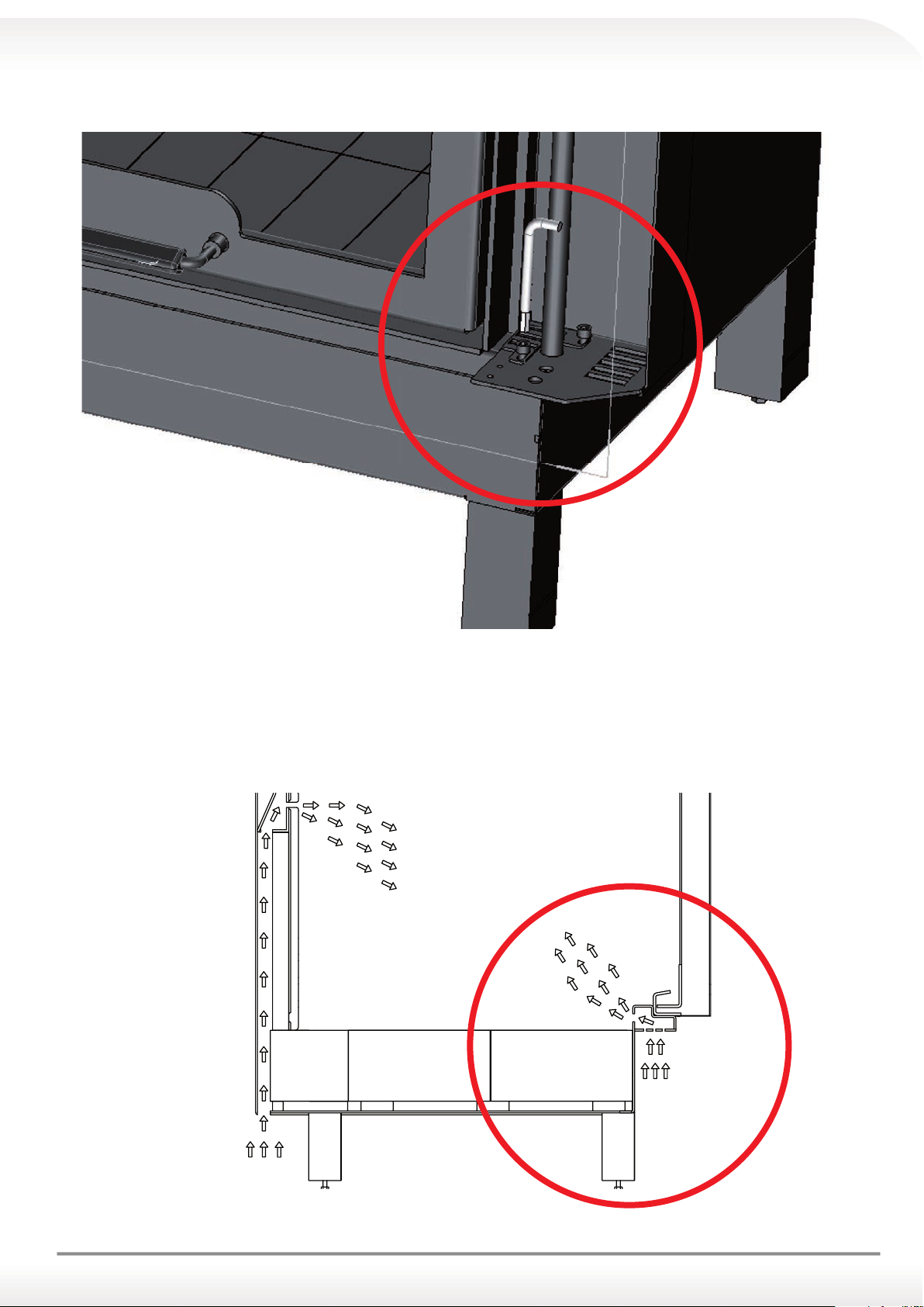
8.3 PRIMARY AIR ADJUSTMENT
SEZ. A-A
To make the adjustments:
a) Remove the side covering;
b) Adjust the grill using the specific Allen key (the picture in paragraph 14.4 shows the air inlet);
c) Check the right amount of combustive secondary air;
d) Put back the side covering;
8.4 SECONDARY AIR
The secondary air improves combustion in the upper part of the combustion chamber. For proper functioning, it is
necessary to leave an aeration grill in order to ensure the right amount of combustive air.
SECONDARY AIR INLET
PRIMARY AIR INLET
29
Page 30
8.5 INSPECTIONS
Once installation and adjustments have been performed, proceed to the following inspections:
a) Check correct smoke evacuation;
b) Check water-tightness;
c) Check functioning of system;
d) Check the thermo fireplace efficiency
8.6 PROPER FUNCTIONING
Thermo fireplace CARINCI EVOLUTION, during performance tests, was loaded with wood and adjusted in this way:
CARINCI EVOLUTION 150/200 CARINCI EVOLUTION 250/300
Loads for efficiency test
Combustive air range adjustment
Test Duration
4.4 kg (n. 4 beechwood logs 30 cm ) 6.0 kg (n. 5 beechwood logs 30 cm)
Primary air: 2 mm opening width
Secondary air: wide open
Glass screen air: 1/3 open
45 min 45 min
Primary air: 2 mm opening width
Secondary air: wide open
Glass screen air: 1/3 open
9.0 COVERING
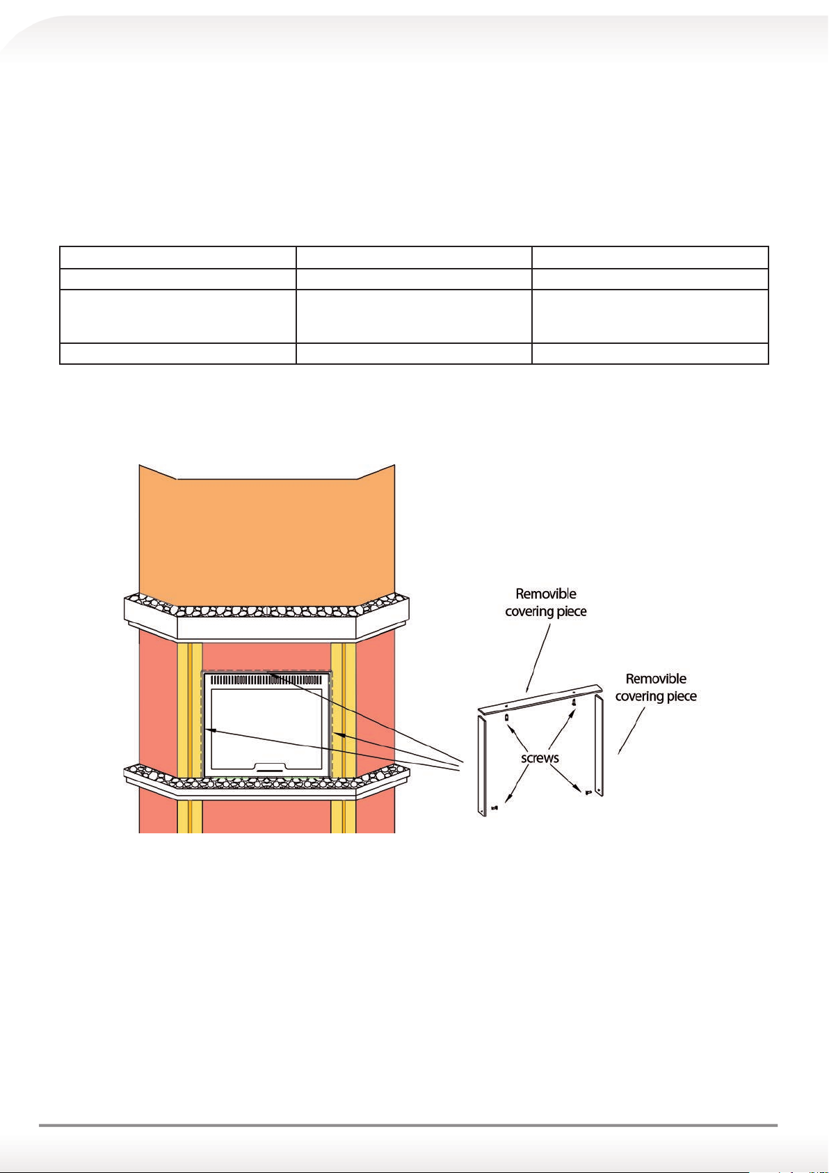
The thermo fireplace CARINCI must be fully upholstered, except only for the glass shutter.
Any maintenance of the sliding can be performed without dismantling any element of the covering but only removing the
side covering (see figure) (see figure)
The Carinci Group SpA recommends, before upholstering the thermo fireplace, to make all efficiency checks of the thermo
fireplace and keep it running for a few weeks.
In the testing phase, it is possible to make some intervention or replacement but, once the covering is assembled, the
customer attests to the validity of the product in all its performances, thus the thermo fireplace replacement right loses its
validity.
The Carinci Group SpA, with its qualified technicians is always available for guidance and/or advices, please contact our customer service at +39 0776/812704 Monday-Friday working hours.
30
Page 31

10.0 RECOMMENDATIONS FOR USE
16.1 USING THE THERMO FIREPLACE CARINCI EVOLUTION IN ADVERSE WEATHER CONDITIONS
If the thermo fireplace is installed in areas at risk of frost, it is recommended to:
a) Install an insulated expansion vessel;
b) Insulate the safety and load pipes;
c) Pour a quantity of antifreeze liquid proportioned to the amount of water in the expansion vessel, and on the basis of
the minimum temperatures of the area, in order to avoid water freezing.
10.2 DOOR OPENING
If the thermo fireplace is in operation, it is recommended to use a fireproof glove to open the door.
10.3 USE OF THE THERMO FIREPLACE CARINCI WITH OPEN DOOR
In case of use of the thermo fireplace with open door, it is recommended to ventilate the room keeping a door or window open.
10.4 SUDDEN SWITCHING OFF OF THE THERMO FIREPLACE CARINCI EVOLUTION
In case it is necessary to switch off the thermo fireplace, it is recommended:
a) To take a normal bottle or something similar, fill it with water and pour it uniformly on the wood until the extinction
of the fire;
b) Once the fire is extinguished, remove the wood from the combustion chamber of the thermo fireplace;
c) Remove the ash with the specific ash shovel;
d) Air the room.
10.5 OVERHEATING
Should the thermo fireplace reach high temperatures, use the secondary exchanger inside the Thermo fireplace for the
production of sanitary hot water as a heat sink for the excess energy, open a tap water connected to it and wait until
the temperature decreases.
10.6 POSSIBLE MALFUNCTIONS
In the presence of the following possible malfunctions it is recommended to extinct the fire:
a) Block of the circulator
b) Failure of the control unit;
c) Blockage of the flue;
d) Lack of water in the expansion vessel.
11.0 CLEANING OF THE THERMO FIREPLACE CARINCI EVOLUTION
Shown below, some simple cleaning up actions to do every day:
11.1 GLASS CLEANING
a) It is recommended to clean the glass when the thermo fireplace is off;
b) Open the shutter-door;
c) Use of a non-abrasive cloth;
d) Proceed to clean the glass using CARINCI glass cleaner or a similar product.
11.2 BOILER COMPARTMENT CLEANING
a) It is recommended to clean the boiler compartment when the thermo fireplace is off;
b) Take the ash shovel;
c) Remove all the ash and put it in a metal container;
d) Wait for the ash to cool down and proceed to dispose of it in the appropriate containers.
31
Page 32
12.0 ROUTINE MAINTENANCE
We recommend the following routine maintenance be carried out for our product.
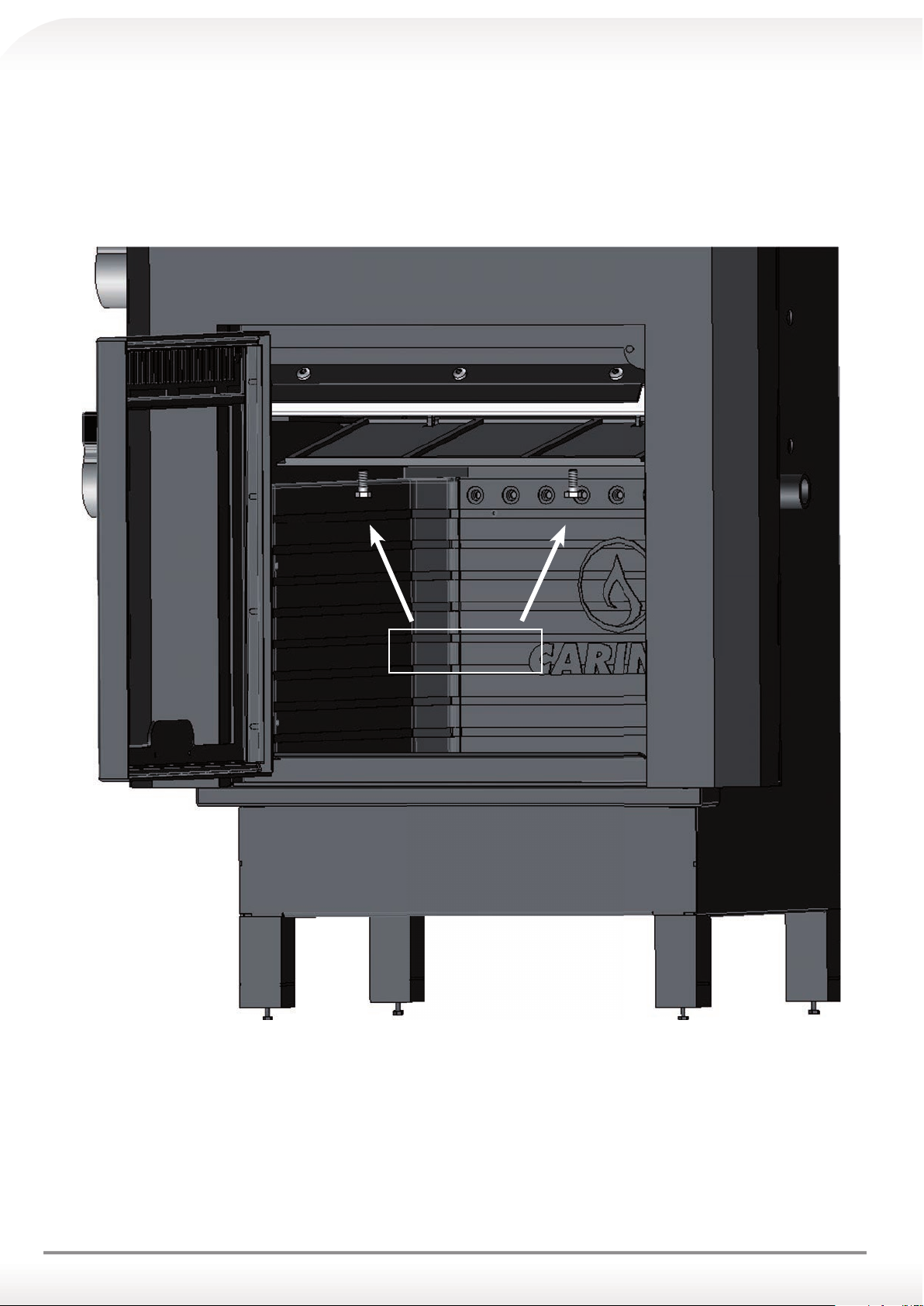
12.1 HEAT EXCHANGERS CLEANING
At least twice a year, the inside of the combustion chamber should be cleaned following these easy steps:
a) Open the shutter-door of the thermo fireplace;
b) Unscrew the two screws located on the front side of the cast iron plate and open it.
Fastening
screws
32
Page 33
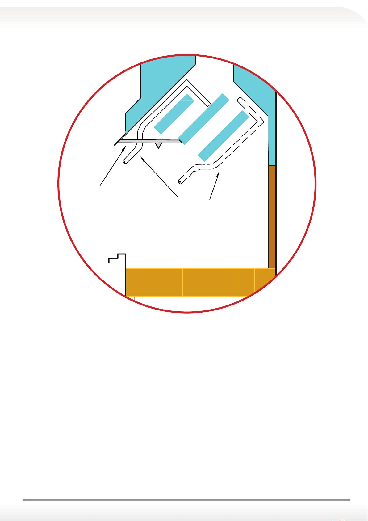
c) Perform the cleaning of the exchangers using the specific scraper supplied with the thermo fireplace;
plate to take away
based thermo replace
scraper
d) Once the cleaning is completed, put back the cast iron plate rescrewing the two screws removed beforehand.
CAUTION!!!
For your personal safety, before proceeding with the cleaning of the thermo fireplace, make sure
that the combustion chamber is cold. It is mandatory to use gloves resistant to high temperatures.
33
Page 34

12.2 INSPECTION OF CORRECT FUNCTIONING
Before switching on the boiler for the first time during the winter season, it is advisable to:
a) Check the circulator is functioning correctly;
b) Check for any obstructions in the flue due to the machinery not being used for a long period of time;
c) Check the control unit is functioning correctly;
d) Check the chimney stack for any obstructions such as bird nests or beehives, etc.
e) Check the air intake is functioning correctly;
f) Check the inspection plate inside the combustion chamber of the thermo fireplace;
g) Check the proper content of water in the thermo fireplace through the expansion vessel,
13.0 EXTRAORDINARY MAINTENANCE
Due to incorrect use of certain components of our thermo fireplace, you may experience a few unpleasant events that
require extraordinary maintenance. Here is some advice, but we always recommend to contact our customer service
office (tel no: +39 0776 812704 ) or technical assistance representative.
13.1 GLASS REPLACEMENT
The replacement of the glass is a procedure that requires more attention, therefore it is recommended to follow these
steps:
a) Open the shutter-door;
b) Remove the screws of the frame glazing;
c) Remove the frame glazing;
d) Pull out the glass carefully;
e) Thoroughly clean the frame and the glass support compartment;
f) Replace the glass;
g) Replace the glass-structure with the proper seal;
h) Tighten the screws of the glass-structure with caution in order to avoid the glass breaking.
13.2 HANDLE REPLACEMENT
To replace the handle, it is recommended to do the following steps (respecting the paragraph 17.1):
a) Remove the glass;
b) Remove the screws of the handle;
c) Replace the handle
d) Reassemble the glass.
34
Page 35
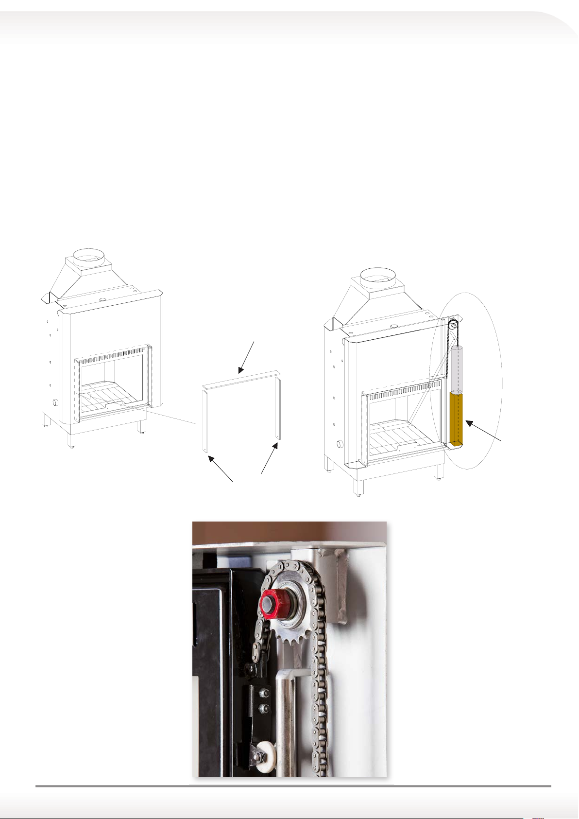
13.3 SLIDING MECHANISM LOCK
Due to incorrect transport and displacement movements of the thermo fireplace, the sliding mechanism lock of the door
can become detached from the chain from the pinion.
To restore the sliding door perform the following procedures:
a) Unscrew the four screws located on the removable covering, the screws on the side first, then those on the upper
removable covering (see figure A)
b) Raise the counterweight;
c) Take the counterweight raised with a support made of wood or similar to facilitate the re-alignment of the chain on
the pinion; (see figure B)
d) Insert a hand inside the door and hang up the chain on the pinion. I If the hand does not fit, use an iron hook (see
figure B)
e) Once the chain is hung up properly, remove the support of the counterweight positioned before;
f) Re-tighten the screws of the removable covering, the upper ones first, then the side ones. (see the right position as
shown in figure C)
Figure A Figure B
Removable
cover
Figure C
Support
in wood
Removable
cover
35
Page 36
14.0 TECHNICAL DATA
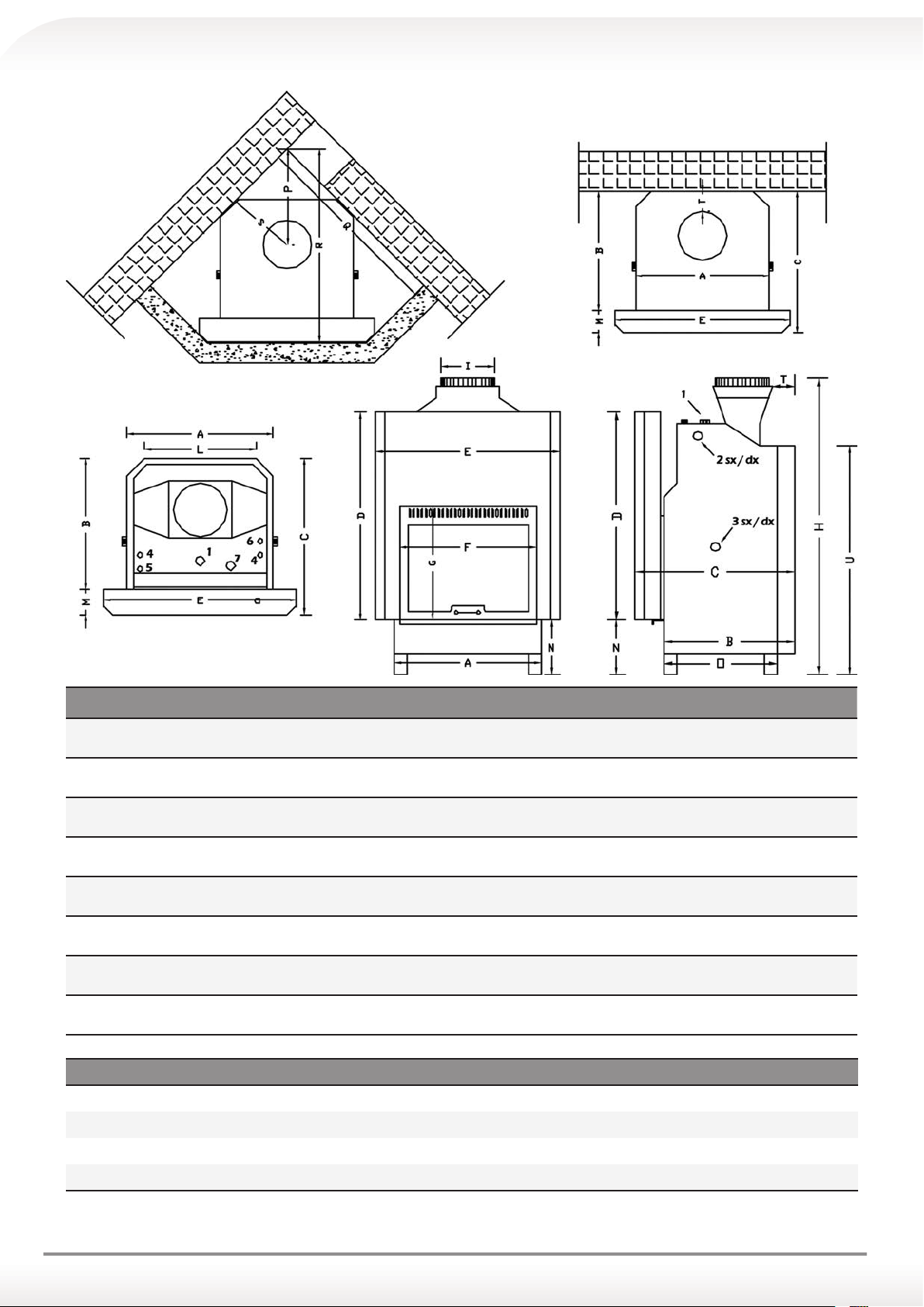
Nr. Thermo Fireplace Connections Mod. 140 - 190 - 240 - 290 Type of junction Ø
1 Safety exit Female junction 1”1/4
2 sx/dx Heating system flow Female junction 1”1/4
3 sx/dx Heating system return Female junction 1”1/4
3 sx/dx Filling pipe Female junction 1”1/4
4 Probe junction Female junction 1/2
5/6 Hot sanitary water outlet Male junction 3/4
6/5 Hot sanitary water inlet Male junction 3/4
7 Filling pipe (System) Female junction 1”1/4
Model A B C D E F G H I L M N O P Q R S T U
150
200
250
300
56 60 71 95 77 52 55 142 25 40 11 27 52 43 89 89 30 11 109
67 60 71 95 88 63 55 148 25 51 11 27 52 48 97 97 34 11 109
78 60 71 95 99 74 55 153 25 62 11 27 52 53 105 105 38 11 109
89 60 71 95 110 85 55 157 25 73 11 27 52 58 113 113 42 11 109
36
Page 37

EVOLUTION G EVOLUTION R
150 200 250 300
Thermal Power
Thermal Power
Nominal
Heating Power
Performance
(environment)
Heating Power
on water
Yield 83% 83.5% 83.5% 84% 83% 83.5% 83.5% 84% 83% 83.5% 84.5% 85.5% 83% 83.5% 84.5% 85.5%
CO measured
at 13% O
2
Temperature of
exhaust gas
Fireplace
minimum draft
requirements
25,1 kW28 kW31 kW34.2 kW25.1 kW28 kW31 kW34.2 kW24.6 kW28 kW31 kW34.2 kW24.6 kW28 kW31 kW34.2
20.5 kW23 kW26 kW28.5 kW20.5 kW23 kW26 kW28.5 kW20 kW23 kW26 kW29 kW20 kW23 kW26 kW29
5 kW
15.5 kW16.5 kW17.5 kW18.5 kW15.5 kW16.5 kW17.5 kW18.5 kW12 kW14 kW16.5 kW19 kW12 kW14 kW16.5 kW19
0.13% 0.13% 0.15% 0.15% 0.13% 0.13% 0.15% 0.15% 0.09% 0.09% 0.14% 0.14% 0.09% 0.09% 0.14% 0.14%
201 °C201 °C176 °C176 °C201 °C201 °C176 °C176 °C199 °C199 °C194 °C194 °C199 °C199 °C194 °C194
12 ±
2 Pa
6.5 kW8.5 kW10
12 ±
12 ±
2 Pa
2 Pa
150 200 250 300 150 200 250 300
5 kW
kW
12 ±
12 ±
2 Pa
2 Pa
SYSTEM
6.5 kW8.5 kW10
12 ±
12 ±
2 Pa
2 Pa
kW
12 ±
2 Pa
150 200 250 300
8 kW 9 kW
12 ±
12 ±
2 Pa
2 Pa
9.5 kW10
12 ±
12 ±
2 Pa
2 Pa
kW
8 kW 9 kW
12 ±
2 Pa
12 ±
2 Pa
SYSTEM
9.5 kW10
12 ±
12 ±
2 Pa
2 Pa
kW
kW
kW
kW
°C
Combustion gas
volumetric
flux
Sanitary
Maximum
Water Pressure
Sanitary
Maximum
Water Pressure
Boiler
Contained Water
Convective air
inlet minimum
section
Convective air
outlet minimum
section
Mass
of the Appliance
Fumes junction
Flammable
materials minimum
security distance
19,3
22,4
25,5
28,6
19,3
22,4
25,5
28,6
20,1
21,1
g/s
g/s
g/s
g/s
g/s
g/s
g/s
g/s
g/s
3,5
3,5
3,5
3,5
3,5
3,5
3,5
3,5
bar
bar
bar
bar
bar
bar
bar
1,5
1,5
1,5
1,5
1,5
1,5
bar
bar
bar
bar
bar
69 lt 82 lt 95 lt 111 lt 69 lt 82 lt 95 lt 111 lt 69 lt 82 lt 95 lt 111 lt 69 lt 82 lt 95 lt 111 lt
300 x
300 x
300 x
300 x
300 x
200
200
200
mm
mm
300 x
300 x
200
mm
300 x
200
mm
285 kg325 kg365 kg405 kg310 kg350 kg390 kg430 kg285 kg325 kg365 kg405 kg310 kg350 kg390 kg430
250 mm250 mm250 mm250 mm250 mm250 mm250 mm250 mm250 mm250 mm250 mm250 mm250 mm250 mm250 mm250
200 mm200 mm200 mm200 mm200 mm200 mm200 mm200 mm200 mm200 mm200 mm200 mm200 mm200 mm200 mm200
mm
200
mm
200
mm
300 x
200
mm
200
mm
300 x
200
mm
300 x
300 x
bar
200
mm
200
mm
1,5
bar
300 x
200
mm
300 x
200
mm
300 x
200
300 x
200
bar
1,5
bar
mm
mm
3,5
bar
1,5
bar
300 x
200
mm
300 x
200
mm
300 x
300 x
g/s
3,5
bar
1,5
bar
200
mm
200
mm
22,1
g/s
3,5
bar
1,5
bar
300 x
200
mm
300 x
200
mm
23
g/s
3,5
bar
1,5
bar
300 x
200
mm
300 x
200
mm
20.1
g/s
3,5
bar
1,5
bar
300 x
200
mm
300 x
200
mm
21.1
g/s
3,5
bar
1,5
bar
300 x
200
mm
300 x
200
mm
22.1
g/s
3,5
bar
1,5
bar
300 x
200
mm
300 x
200
mm
23
g/s
3,5
bar
1,5
bar
300 x
200
mm
300 x
200
mm
kg
mm
mm
37
Page 38

38
Page 39

39
Page 40

GENERAL WARRANTY CONDITIONS
heating system innovations
The Carinci Group SpA guarantees its equipment on the Italian territory in accordance with the European Directive 99/44/CE (European warranty).
Our products are guaranteed against manufacturing defects for 2 (two) years from the date of purchase as required under European warranty, only if proof of purchase may be provided in the form of a
proof of purchase document and the ‘Protocol for Use’. Within this period, at the discretion of the Carinci Group SpA, the buyer will have the right to repair free of charge, or the replacement of defective
parts, excluding glass, bricks and ceramic plates. No parts subject to wear or consumable parts fall under the provisions of the warranty. All of the warranty conditions are specified more clearly in the
following articles:
Art. 1 – Product compliance
a. The Carinci Group SpA guarantees the compliance of its equipment with the descriptions given on the information leaflets and instruction manuals.
b. The Carinci Group SpA is committed to the resolution of conformity defects and, wherever this is not possible, to the withdrawal and reimbursement of the single device for its conformity defect,
if and only if reported within the period of 6 (six) months from the date of purchase. No other benefits may be requested from the Carinci Group SpA, including compensation.
Art. 2 – Right to warranty
The Carinci Group SpA recognizes the right to warranty only if:
a. The equipment has been installed in an appropriate and professional manner by qualified and authorised personnel and otherwise, in general, with respect for the regulations in force and those
contained in the "User Manual"
b. The Carinci Group SpA receives within 10 days by registered post, the “Protocol for Use” along with the “Warranty Certificate”, duly completed in all their parts, stamped and signed by the authorised
technician, and undersigned by the final user.
c. Fiscal documentar y evidence, which can prove purchase, and a validated copy from T.A.C. of “Warranty general conditions” (Ref. Art. 2 par. B) must be kept and shown on request from authorised
Carinci Group SpA personnel only.
d. Use of the equipment according to the methods described in the “User’s Manual” supplied therewith.
Art. 3 – Limits of warranty
The Carinci Group SpA shall not acknowledge any right to warranty on failure to meet one or more of the conditions listed in the following points:
a. Damage caused by transport and not reported within 2 days of occurrence.
b. Damage caused by storage that is not compatible with the nature of the equipment.
c. Damage not directly attributable to manufacturing defects, defects caused by incorrect installation, incorrect use, alterations of any kind and/or repairs carried out by personnel not expressly
authorised by the Carinci Group SpA.
d. Damage to the boiler unit caused by an operating pressure greater than 2 bar.
e. Clogging of the copper heat exchanger for hygienic and sanitary use caused by the deposit of minerals, impurities, residues present in the water of the water and sanitar y system or of any other
foreign element
f. Damage to the copper heat exchanger for hygienic and sanitary use caused by blows and by pressures in the water and sanitary system greater than 3 bar.
g. Any loss of water due to puncture of the boiler unit caused by normal corrosive processes of an electrochemical or electrostatic nature, or due to stray currents, atmospheric agents, etc.
h. For any defects or failures of electrical, electronic or mechanical components due to force majeure and not foreseeable by the Carinci Group SpA, which includes power surges, lightning bolts,
proximity to high voltage trellises or other devices in the environment in which the equipment is placed that provoke magnetic fields.
i. Damage caused by an inadequate electrical system whose grounding does not comply.
j. For variations in colour, scratches to the paintwork or other alterations that occur due to normal use and high temperatures.
k. For defects or malfunctions caused by: inadequate drafts from the chimney stack, installation of an incorrect chimney stack, lack of oxygen needed in the environment in which the equipment
is installed.
l. For clogging of the exchangers caused by inappropriate use of the product or the use of an unsuitable fuel.
m. For corrosion of the equipment caused by condensed acid poured directly from the chimney into the boiler unit.
Art. 5 - Exclusions
The Carinci Group SpA will not recognize in the warranty guarantee any interventions carried out for:
a. Operating defects caused by poor chimney draft;
b. Operating defects caused by issues with the thermal system;
c. Operating defects caused by the quality of the fuel;
d. Operating defects caused by use of a fuel different to that which is specified;
e. Operating defects caused by the presence of foreign bodies in the equipment;
f. Operating defects caused by deposits on account of non-routine cleaning;
g. Operating defects caused by improper use;
All costs incurred by the company in the event of proven traceability to one of the points mentioned shall be charged to the final user.
Art. 6 – Repairs or replacements
a. All repairs or replacements carried out under warranty should be done so exclusively by specialised personnel and those authorised in advance by the Carinci Group SpA.
b. Repair or replacement under warranty does not produce an extension of the warranty period and more specifically also any replacement or repaired parts will have the same contractual expiry
as the remainder of the equipment components.
Art. 7 - Costs
The Carinci Group SpA, in the case of acknowledgment of a manufacturing defect, shall only cover the costs of the expenses incurred for the repair or replacement of those elements considered
defective. All other costs incurred, such as that of disassembly, reassembly, any costs associated with masonry or transport, shall be entirely the responsibility of the client and user.
Art. 8 – First Ignition of the Generator, regulation and validation warranty
a. The Carinci Group SpA shall carry out through authorised personnel the regulation and the validation of the warranty of its equipment (with the exception of equipment that functions only
with wood) and it will be verbalised in the compilation of the ‘Warranty Certificate.’
b. The cost of any subsequent interventions to the ‘initial activation of the generator,’ due to failures or causes not directly attributable to the Carinci Group S.p.A. or to personnel authorised
by the latter, who have caused the failure before the ‘first ignition of the generator,’ shall be entirely the responsibility of the client.
c. All successive inter ventions for control or regulation of parameters carried out at the house of the client, by request of the latter, shall be entirely at his cost in addition to the call fee.
Art. 9 – Limitations of liability
a. No compensation for any period of inefficacy of the product shall be given.
b. Damages resulting directly or indirectly from persons, things or animals as a consequence of non-compliance with the regulations of this document, “GENERAL WARRANTY CONDITIONS” and the
specifications indicated in the “User’s Manual”.
Art. 10 - Privacy
The characteristics are described in the “User’s Manual” supplied with the equipment, the client declares receipt, reading and integral knowledge of all of its contents. The client also declares
knowledge of the safety rules and the necessary precautions for use of the equipment and routine maintenance, undertaking to observe these.
Art. 11 - Ownership
The warranty is nominal and it belongs exclusively to the holder of the proof of purchase document and the ‘Protocol for use,’ this may not be assigned or transferred in any way to third parties.
Therefore only the owner of the equipment may request technical assistance services under the warranty.
Art. 12 – Court of Jurisdiction
The Carinci Group SpA defines and elects the court of Frosinone as the seat of jurisdiction for any disputes.
T.A.C. (Stamp and signature) - date ____/____/_______)
COPY FOR THE CLIENT
Page 41

PROCEDURAL GUIDE ON IGNITING THE MACHINERY FOR THE FIRST TIME
The T.A.C., only when authorised in advance by CARINCI GROUP S.p.A., can perform the "Set Up" procedure:
STAGE 1: Regulating the combustion
To cut out and post
30 minutes after ignition, regulate the combustion using the designated regulators on the extractor speed (combustion air input)
and auger speed (fuel input).
Note the settings of:
Fan parameter Auger parameter
Upon ignition
30 minutes after switching on
60 minutes after switching on
STAGE 2: Filling out the "Warranty Certicate"
Fill out the "Warranty Certicate" and validate a copy for the Client.
Name................................................................................. Surname.............................................................................
Address................................................................................................................................... .................... Post code................ .........................................
City............................................................................................................. (Province ......) Tel. ........................................................
CARINCI MACHINERY Mod. ...................................................................... Matriculation No. .....................................................
Date of purchase ..................................... Seller
..............................................................................................................................................................
City........................................................................................................................................................ (Province ......) Tel. ........................................................
Installation Company T.A.C. (insert the date of the "Set Up Protocol" where requested (Art. 8 Par. a) - date / /
I agree to the treatment of my personal data in accordance with Legislative Decree 196/2003. I declare to fully accepting the "General Terms and Conditions of Warranty", to having received all the
information required to use the machinery correctly and to possessing all the introduction Manuals and having read them in their entirety.
Signature ............................................................................................................................
)
....
....
Page 42

GENERAL WARRANTY CONDITIONS
heating system innovations
CARINCI GROUP SpA - Operational/Administrative Headquarters: Via Felci (industrial area) - 03039 Sora (FR) • Tel.: +39 0776 812704 • Fax: +39 0776 81439
The Carinci Group SpA guarantees its equipment on the Italian territory in accordance with the European Directive 99/44/CE (European warranty).
Our products are guaranteed against manufacturing defects for 2 (two) years from the date of purchase as required under European warranty, only if proof of purchase may be provided in the form of a proof of purchase
document and the ‘Protocol for Use’. Within this period, at the discretion of the Carinci Group SpA, the buyer will have the right to repair free of charge, or the replacement of defective parts, excluding glass, bricks and
ceramic plates. No parts subject to wear or consumable parts fall under the provisions of the warranty. All of the warranty conditions are specified more clearly in the following articles:
Art. 1 – Product compliance
a. The Carinci Group SpA guarantees the compliance of its equipment with the descriptions given on the information leaflets and instruction manuals.
b. The Carinci Group SpA is committed to the resolution of conformity defects and, wherever this is not possible, to the withdrawal and reimbursement of the single device for its conformity defect, if and only if
reported within the period of 6 (six) months from the date of purchase. No other benefits may be requested from the Carinci Group SpA, including compensation.
Art. 2 – Right to warranty
The Carinci Group SpA recognizes the right to warranty only if:
a. The equipment has been installed in an appropriate and professional manner by qualified and authorised personnel and other wise, in general, with respect for the regulations in force and those contained in the
"User Manual"
b. The Carinci Group SpA receives within 10 days by registered post, the “Protocol for Use” along with the “Warranty Certificate”, duly completed in all their parts, stamped and signed by the authorised technician,
and undersigned by the final user.
c. Fiscal documentar y evidence, which can prove purchase, and a validated copy from T.A.C. of “Warranty general conditions” (Ref. Art. 2 par. B) must be kept and shown on request from authorised Carinci Group
SpA personnel only.
d. Use of the equipment according to the methods described in the “User’s Manual” supplied therewith.
Art. 3 – Limits of warranty
The Carinci Group SpA shall not acknowledge any right to warranty on failure to meet one or more of the conditions listed in the following points:
a. Damage caused by transport and not reported within 2 days of occurrence.
b. Damage caused by storage that is not compatible with the nature of the equipment.
c. Damage not directly attributable to manufacturing defects, defects caused by incorrect installation, incorrect use, alterations of any kind and/or repairs carried out by personnel not expressly authorised by the
Carinci Group SpA.
d. Damage to the boiler unit caused by an operating pressure greater than 2 bar.
e. Clogging of the copper heat exchanger for hygienic and sanitary use caused by the deposit of minerals, impurities, residues present in the water of the water and sanitar y system or of any other foreign element
f. Damage to the copper heat exchanger for hygienic and sanitar y use caused by blows and by pressures in the water and sanitary system greater than 3 bar.
g. Any loss of water due to puncture of the boiler unit caused by normal corrosive processes of an electrochemical or electrostatic nature, or due to stray currents, atmospheric agents, etc.
h. For any defects or failures of electrical, electronic or mechanical components due to force majeure and not foreseeable by the Carinci Group SpA, which includes power surges, lightning bolts, proximity to high
voltage trellises or other devices in the environment in which the equipment is placed that provoke magnetic fields.
i. Damage caused by an inadequate electrical system whose grounding does not comply.
j. For variations in colour, scratches to the paintwork or other alterations that occur due to normal use and high temperatures.
k. For defects or malfunctions caused by: inadequate drafts from the chimney stack, installation of an incorrect chimney stack, lack of oxygen needed in the environment in which the equipment is installed.
l. For clogging of the exchangers caused by inappropriate use of the product or the use of an unsuitable fuel.
m. For corrosion of the equipment caused by condensed acid poured directly from the chimney into the boiler unit.
Art. 5 - Exclusions
The Carinci Group SpA will not recognize in the warranty guarantee any interventions carried out for:
a. Operating defects caused by poor chimney draft;
b. Operating defects caused by issues with the thermal system;
c. Operating defects caused by the quality of the fuel;
d. Operating defects caused by use of a fuel different to that which is specified;
e. Operating defects caused by the presence of foreign bodies in the equipment;
f. Operating defects caused by deposits on account of non-routine cleaning;
g. Operating defects caused by improper use;
All costs incurred by the company in the event of proven traceability to one of the points mentioned shall be charged to the final user.
Art. 6 – Repairs or replacements
a. All repairs or replacements carried out under warranty should be done so exclusively by specialised personnel and those authorised in advance by the Carinci Group SpA.
b. Repair or replacement under warranty does not produce an extension of the warranty period and more specifically also any replacement or repaired par ts will have the same contractual expiry as the remainder
of the equipment components.
Art. 7 - Costs
The Carinci Group SpA, in the case of acknowledgment of a manufacturing defect, shall only cover the costs of the expenses incurred for the repair or replacement of those elements considered defective. All
other costs incurred, such as that of disassembly, reassembly, any costs associated with masonry or transport, shall be entirely the responsibility of the client and user.
Art. 8 – First Ignition of the Generator, regulation and validation warranty
a. The Carinci Group SpA shall carr y out through authorised personnel the regulation and the validation of the warranty of its equipment (with the exception of equipment that functions only with wood)
and it will be verbalised in the compilation of the ‘Warranty Certificate.’
b. The cost of any subsequent inter ventions to the ‘initial activation of the generator,’ due to failures or causes not directly attributable to the Carinci Group S.p.A. or to personnel authorised by the latter, who have
caused the failure before the ‘first ignition of the generator,’ shall be entirely the responsibility of the client.
c. All successive interventions for control or regulation of parameters carried out at the house of the client, by request of the latter, shall be entirely at his cost in addition to the call fee.
Art. 9 – Limitations of liability
a. No compensation for any period of inefficacy of the product shall be given.
b. Damages resulting directly or indirectly from persons, things or animals as a consequence of non-compliance with the regulations of this document, “GENERAL WARRANTY CONDITIONS” and the specifications
indicated in the “User’s Manual”.
Art. 10 - Privacy
The characteristics are described in the “User’s Manual” supplied with the equipment, the client declares receipt, reading and integral knowledge of all of its contents. The client also declares knowledge of the
safety rules and the necessary precautions for use of the equipment and routine maintenance, undertaking to observe these.
Art. 11 - Ownership
The warranty is nominal and it belongs exclusively to the holder of the proof of purchase document and the ‘Protocol for use,’ this may not be assigned or transferred in any way to third parties. Therefore only
the owner of the equipment may request technical assistance services under the warranty.
Art. 12 – Court of Jurisdiction
The Carinci Group SpA defines and elects the court of Frosinone as the seat of jurisdiction for any disputes.
COPY TO BE SENT TO CARINCI GROUP SPA TO VALIDATE THE WARRANTY
DISPATCH ADDRESS OF THE WARRANTY CERTIFICATE
Client's signature
Page 43

© 2016 Carinci Group S.p.A.
Reproduction, also partial, is forbidden - I ed. January 2016
Page 44

 Loading...