

Page 1
LB.05080.00 Pag.1 16/04/2014
TECHNICAL
INSTRUCTIONS
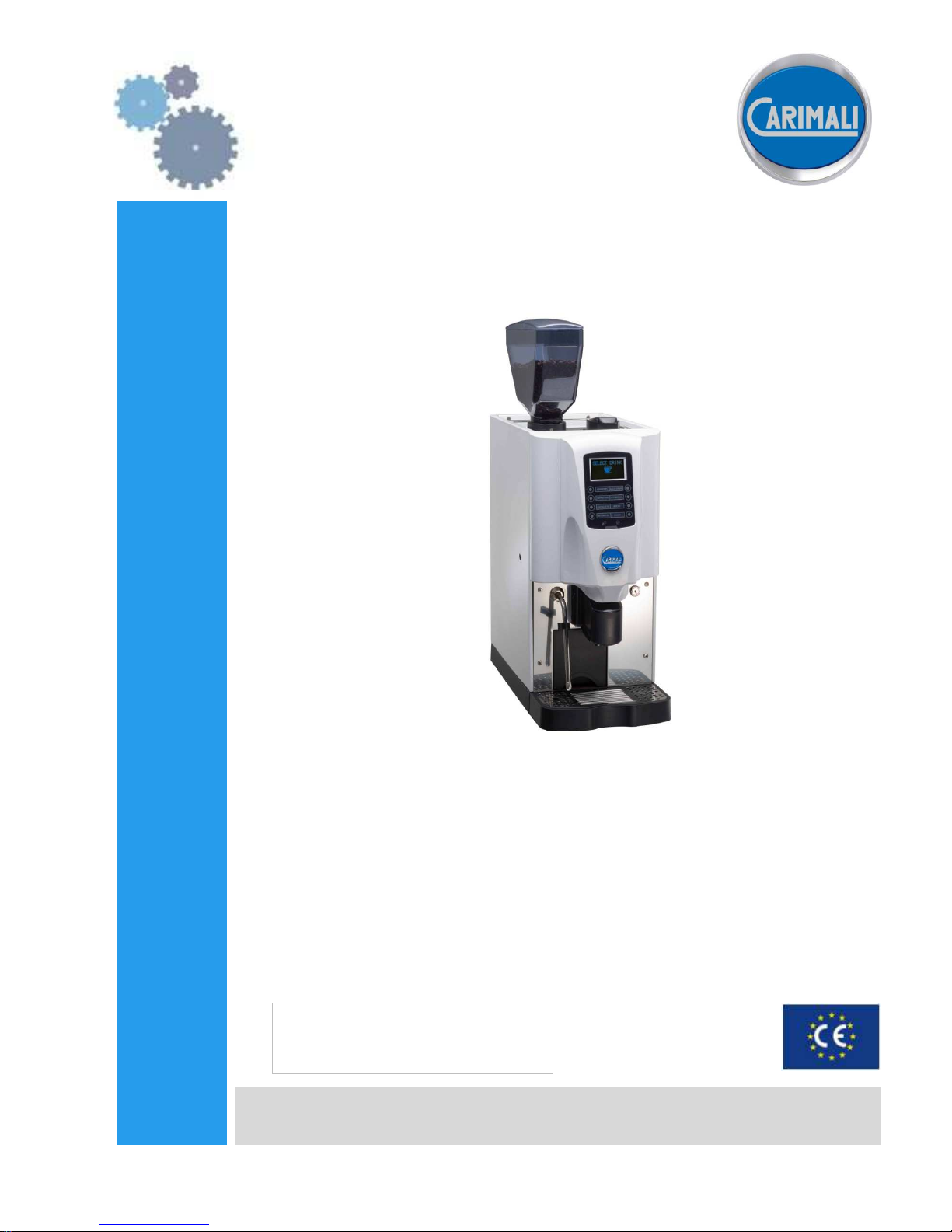
MULTI
SMART
www.carimali.com
LB-05080.00 EN
EDITION February 2014
EN ENGLISH
Page 2

LB.05080.00 Pag.2 16/04/2014
TABLE OF CONTENTS
GENERAL CHARACTHERISTICS .................................................................................................................................................................................. 5
TEST REPORT ON ENERGY CONSUMPTION ............................................................................................................................................................. 7
MACHINE KEYPAD ........................................................................................................................................................................................................... 7
ELECTRIC - HYDRAULIC CONNECTION .................................................................................................................................................................... 8
STARTING UP ..................................................................................................................................................................................................................... 9
ACCESS THE MAIN SETTING MENUS WITH PASSWORD .................................................................................................................................... 13
PROGRAMMABLE PARAMETERS IN ACCORDING WITH PASSWORD ............................................................................................................ 14
INFO-RESET ...................................................................................................................................................................................................................... 16
DOSES PROGRAMMING ................................................................................................................................................................................................ 20
SYSTEM MANAGER ........................................................................................................................................................................................................ 25
MACHINE CONFIGURATION ....................................................................................................................................................................................... 42
PRESET PARAMETERS .................................................................................................................................................................................................. 44
CLEANING PROCESS ABORT ....................................................................................................................................................................................... 45
TROUBLE SHOOTING .................................................................................................................................................................................................... 46
SPECIAL FUNCTIONS FOR MACHINE CALIBRATION .......................................................................................................................................... 51
RECOMMENDATIONS FOR A CORRECT PREVENTIVE MAINTENANCE ........................................................................................................ 52
CONTROL UNIT LEGEND .............................................................................................................................................................................................. 53
Page 3
LB.05080.00 Pag.3 16/04/2014
INTRODUCTION AND GENERAL NOTES
Thoroughly read the instructions contained in this booklet because it gives important information regarding safety for installation, use and
maintenance.
Keep this booklet in a safe and accessible place for further consultation.
This machine must be used only for the purpose it was designed:
dispensing coffee, cappuccino, pouring hot water.
Any other use is to be considered inappropriate and therefore dangerous.
The manufacturer declines all responsibility for damage caused by any improper, incorrect and unreasonable use of the machine.
The use of any electric appliance implies the observance of some fundamental rules.
More specifically:
The appliance should be placed on a stable flat surface with the bodywork at a minimum distance of 20mm from the back wall,
furthermore, it must be installed taking into account that the highest shelf must sit at a height that is at least 1.5 mt.
During installation, fit a device that guarantees disconnection from the mains, duly sized according to the power of the equipment (see
rating plate), as well as protection against leakage current with a value equal to 30mA.This cut-off device must be assembled on the
power supply line in compliance with installation rules.
do not touch the appliance with your hands or feet wet or damp
do not use the appliance with bare feet
do not pull the power cord to disconnect the plug from the power socket
dot not leave the appliance exposed to the weather (rain, sun, frost)
do not let children or untrained persons use the appliance.
Before carrying out any cleaning and maintenance, disconnect the appliance from the power supply, pulling the plug from the power socket
and turning off the main switch.
In case of failure or malfunction turn the machine off and do not attempt to carry out any repairs or direct operations on the machine.
All repairs must be carried out in an authorized service centre, using original spare parts only.
Failure to comply with the above recommendations will compromise the safety of the machine and the warranty conditions.
If this machine is no longer used we recommend that it is made inoperative by disconnecting the cable from the power supply, and all
potentially dangerous parts are made harmless, especially to protect children who might use the machine for their games.
INSTALLATION NOTES
Installation must be carried out according to the manufacturer’s instructions.
An incorrect installation can cause damage to persons, animals or things; the manufacturer declines all responsibility for such situation.
Place the machine on a table having minimum height of 0,95mt. Furthermore the surface has to be flat, having a maximum inclination of 5°,
in order to secure a perfect stability. Check also that the table can bear the weight of the machine.
This is a commercial machine and is not designed for home use and must be operated by duly qualified persons.
The machine must not be used by children or people with reduced mobility, sensory, mental or lack of experience or education, unless there
is a supervisor.
After unpacking check that the machine is not damaged.
If in doubt, do not use the machine and contact an Carimali S.p.A. Authorized Service Centre.
All packing materials (plastic wrapping, polystyrene, nails, etc.) are potentially dangerous and must be kept out of children’s reach and
disposed of in a safe manner for the environment.
Before connecting the machine to the power supply make sure that the rating information of the machine correspond to that of the power
supply, and that the power supply is adequate to additional power absorption of the machine.
The machine is supplied with power cord and without plug, connect the machine to the main switch with knife switch and protection fuses. In
case of maintenance, open the knife switch.
The machine with single phase voltage, having a rated current more than 16A, must be connected to power supply with a dedicated
impedance.
The electrical safety of this machine can be guaranteed only if correctly connected to an efficient earth circuit as indicated by current
electrical safety regulations.
It is necessary to check this fundamental safety prerequisite, and in case of doubt, ask a professionally qualified technician to check the
circuit.
The manufacturer declines all responsibility for any damage caused by failure to earth the equipment.
In order to avoid any dangerous overheating, we recommend that the power cord be fully unwound.
In case of damage to the cord, contact exclusively an authorized service centre to have it replaced.
The power cord of this machine must not be replaced by the customer.
Do not leave the machine connected unnecessarily.
Turn off the main switch of the machine when not in use.
Do not cover the ventilation openings of the machine.
Place the machine at an adequate distance from walls, objects, etc.
The machine must be connected to a system with a water pressure which is not greater than 0.6 MPa. Do not use pipes and coupling
gaskets already used for previous installations.
If the pressure is greater, a pressure reducer must be installed.
The machine must be connected to a softener.
ENVIRONMENTAL CONDITIONS TO USE THE MACHINE
Environmental temperature: 5 – 30 °C (empty the hydraulic system in case of freezing)
Maximum humidity: 80% relative humidity
Water hardness: 5° eh, 7° dH, 13° Fh
Page 4

LB.05080.00 Pag.4 16/04/2014
1. Essential operational requirements
1.1 The machine shall be supplied with water for human consumption, in compliance with the laws in force where the installation is
performed. The installer shall check with the owner or manager of the machine if the water complies with the requirements above.
1.2 The components and materials to be used during the installation are those supplied with the machine. In case other components are
needed, the installer shall check if they are suitable to be used in contact with water for human consumption.
1.3 The installer shall set up hydraulic connections in compliance with the rules about hygiene, water safety and environment in force where
the installation is performed.
1.4 At the end of the installation the machine is activated, brought to nominal operating conditions and left in the “ready for operation” mode.
Then it is turned off and the whole water circuit is drained from the initial water to eliminate any impurities.
Then the machine is once again loaded and brought to nominal operating conditions.
When the machine is in the “ready for operation” mode, the following deliveries are performed:
- 2 liters from the hot water outlet (in case there are more outlets, the 2 liters shall be equally divided)
- 1 liter of water from each coffee outlet
- each steam outlet is kept open for 1 minute
At the end of the installation, it is recommended to write a report of the operations that were performed.
USE AND MAINTENANCE NOTES
For a correct functioning of the machine it is fundamental to comply with the manufacturer’s instructions, having qualified personnel to carry
out special maintenance and to check all safety devices.
Do not use the machine without water.
Avoid to expose hands or other parts of the body to the coffee dispensing spouts or to the steam or hot water nozzles.
The water and steam from the nozzles is very hot and can cause severe burns.
The water and steam nozzles and the filter holders are very hot and therefore must be handled with care, holding them in the appropriate
points.
Do not leave the machine in rooms where the temperature is below 0°C or 32°F without having first drained the boiler and the hydraulic
circuit.
Cups and coffee cups must be placed on the cup-warmer tray (if fitted) only after having been fully drained.
Only the crockery related to the machine should be placed on the cup-warmer tray.
Placing any other object on the tray is to be considered incorrect.
The machine is not waterproof and therefore should not be cleaned with water jet.
1. Use of the machine
1.1 At the beginning of operations, and in any case at least once a day, all the water inside the machine shall be changed, following the
instructions:
- for fully automatic machines, carry out a group washing and a power cleaner washing.
- for traditional machines, see the paragraph about draining the boiler.
1.2 Before the steam wand is used, it shall always be purged from the condensation water for at least 2 seconds or according to the
instructions by the manufacturer.
2. Maintenance and repair
2.1 The components used during the maintenance or repair shall be guaranteed to meet the same hygiene and safety requirements as the
machine. Genuire spare parts offer this guarantee.
2.2 After components related to parts that come into contact with water or food are repaired or changed, a washing procedure shall be
carried out as indicated in the paragraph about the rules for the installation.
HACCP SCHEDULE
We hereby declare that our HORECA machines have been designed and constructed to comply the European Community Sanitary law and
that their sales are authorized by the Health Authorities.
A HACCP schedule (Hazard Analysis Critical Control Points) for risk identification and assessment is required. You should carry out a risk
analysis on your premises.
With correct installation, care, maintenance and cleaning with approved detergent, Carimali meet the requirement above mentioned.
Carry out cleaning instruction, provided with machine, every day or at 8 hours shift intervals, to ensure that your system contains a minimum
bacteria.
Page 5
LB.05080.00 Pag.5 16/04/2014
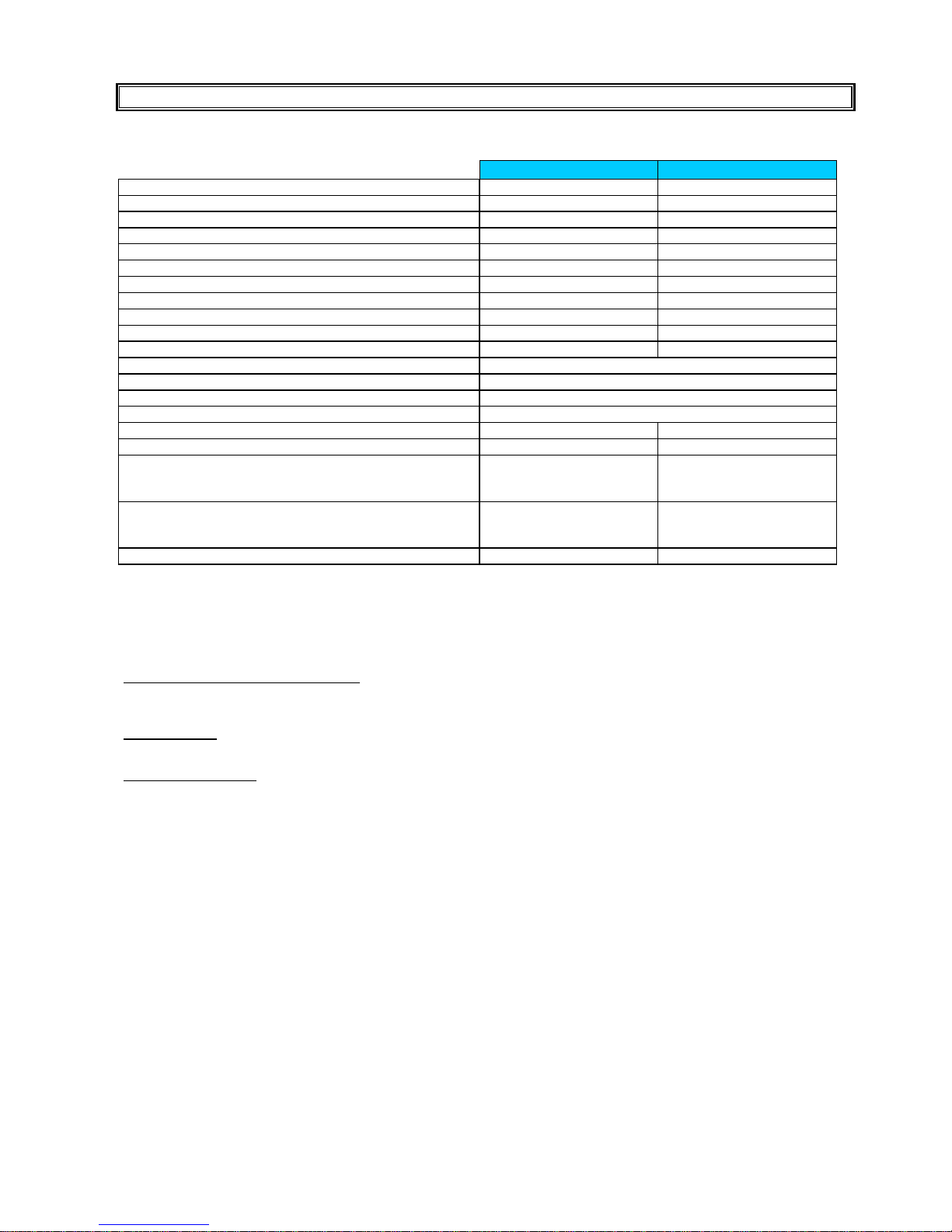
GENERAL CHARACTHERISTICS
MULTI SMART COF MULTI SMART LM
Automatic coffee brewing unit 1 1
Grinder 1 1
Decaffeinated door 1 1
Steam nozzle 1 1
Automatic cappuccino - 1
Hot water dispenser 1 1
Mix Group Optional Optional
Mix cold water Optional Optional
By - Pass Optional Optional
Maximum quantity of coffee dispensed per hour 180 180
Maximum quantity of cappuccino dispensed per hour - 120
Machine Width (mm) 289
Machine height (mm) 592
Machine height with hopper (mm) 814
Machine Depth (mm) 564
Net weight (Kg) 35 35
Boiler capacity (lt) 4 4
Boiler resistor (W) Standard version
Optional version
Optional version
2700+900 (230V~)
2050+710 (200V~)
1200+880 (120V~)
2700+900 (230V~)
2050+710 (200V~)
1200+880 (120V~)
Voltage (V) 230V~ single phase
200V~ single phase
120V~ single phase
230V~ single phase
200V~ single phase
120V~ single phase
Brewer group resistor PTC (W) 70 70
Please note: Multi Smart SELF-version is supplied with hopper with lock and without decaffeinated door and steam
arm.
MACHINES IN SELF CONFIGURATION (see exploded view manual for code number)
Functions are absent or disabled by software:
• extra milk function by pushing the cappuccino/latte dose key: disabled by sw
• function to stop the dose delivery by pushing a dose key: disabled by sw
• function to switch off the machine by pushing Shift and then Info keys: disabled by sw
Included features:
• Kit to block the drip tray
• Kit to block the decaf door
Recommended optionals:
• Lock for beans hoppers
• Direct coffee grounds.
MATERIALS USED:
- Copper for boiler
- Copper and Teflon for hydraulic tubes
- Nickel-plated brass for connections
- Reinforced silicone for the flexible feed tube
- Aluminium with stainless steel lining for the brewing group
- Aluminium for the grinder
- Other accessories in food plastic which are in contact with the ground coffee or drink
- Painted steel bodywork
- ABS plastic for controls area
- Stainless steel and ABS plastic for working area and cups tray.
Page 6

LB.05080.00 Pag.6 16/04/2014
Page 7
LB.05080.00 Pag.7 16/04/2014
TEST REPORT ON ENERGY CONSUMPTION
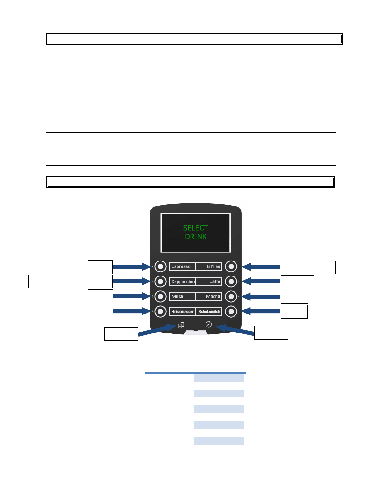
MACHINE KEYPAD
DOSE KEY
FUNCTION
1
Edit
2
Insert blank
3
Delete character
4
Scroll
5
-
6
+
7
Enter
8
Esc
SHIFT
Shift
INFO
Info
Machine type: MULTI SMART
Coffee / Steam boiler heating element 2.7 KW, boiler 4 lt
Machine load 0.940 KW
Environment temperature: 21°C
MEASUREMENT
1. HEAT UP PHASE
To reach operational steam/coffee boiler temperature, 124°C, in 8’.20” (min, sec)
Consumption 0.3 KW/h
HU = 300W/h
2. IDLE PHASE
Stand by at steam/coffee boiler at 124°C during 24 hours
Consumption 3.2 KW/24h
IM = 3200 W/h
3. VENDING PHASE
Delivery of No. 30 cups of coffee of 100ml, one cup every 2 minutes
L = 0.090 Litre
DV = 2700 ml
VM = 450 W/h (vending phase)
DT = 84,4° C (average drink temperature)
ECPL = 166,6 Wh/l (energy consumption per litre)
EDIT
DELETE
CHARACTER
-
ENTER
INSERT BLANK
SCROLL
+
ESC
SHIFT
INFO
Page 8

LB.05080.00 Pag.8 16/04/2014
ELECTRIC - HYDRAULIC CONNECTION
H2O IN
(1-6 Bar)
H2O OUT
WATER
SOFTNER
WATER
Page 9

LB.05080.00 Pag.9 16/04/2014
STARTING UP
After having connected the machine to the water and electric networks, turn the switch on (see diagram).
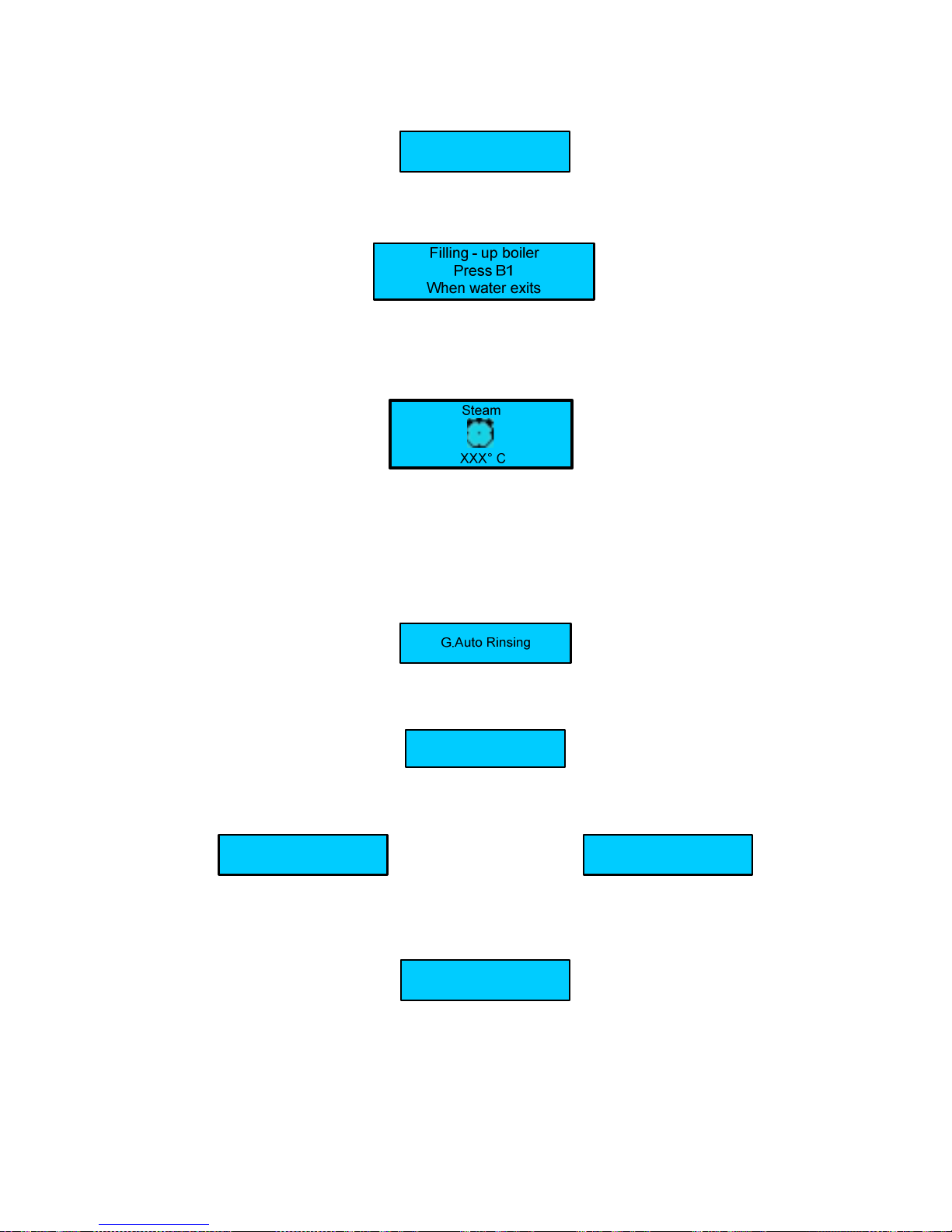
The display shows:
Page 10
LB.05080.00 Pag.10 16/04/2014
keep key n°9 (shift) pressed and then press key n° 10 ( info), and the machine will set itself to on state.
Filling - up steam boiler
During this stage the steam boiler is being filled up.
WARNING
: The solenoid valve of the milker steam automatically opens to release the air inside the boiler.
When the steam boiler has been filled up, the display shows:
During this stage the exchanger is being filled up
WARNING
:
The upper piston of the coffee group positions itself inside the brewing chamber, and the exchanger starts filling up. When
the coffee spout starts dispensing water, press the key dose N° 1 to confirm that the filling up procedure has been carried
out. When the exchanger has been filled up, the display shows:
Where:
- XXX ° C indicates the temperature of the Steam boiler
WARNING
:
A) DURING THIS STAGE THE MILK FROTHER SOLENOID VALVE WILL STAY OPEN UNTIL 95°C. THIS WILL RELEASE THE AIR
FROM THE BOILER.
B)
WHEN THE BOILER TEMPERATURE OF 50°C ITS REACHED THE MACHINE CARRY-OUT A RINSING GROUP, THIS IS
USEFULL TO RELEASE AIR FROM THE WATER COFFEE CIRCUIT; THE DISPLAY WILL SHOW :
When the set-up temperature is reached , the display shows:
For machine configurations: Standard.
Select drink
For machine configurations: Self.
The display shows:
Select drink
Alternated with the message:
Position the cup
For machine configuration: Self with coin box.
The display shows:
Select Drink
WARNING:
a) For Self with coin box configuration the selections doses are enabled only when the set-up temperature has
been reached.
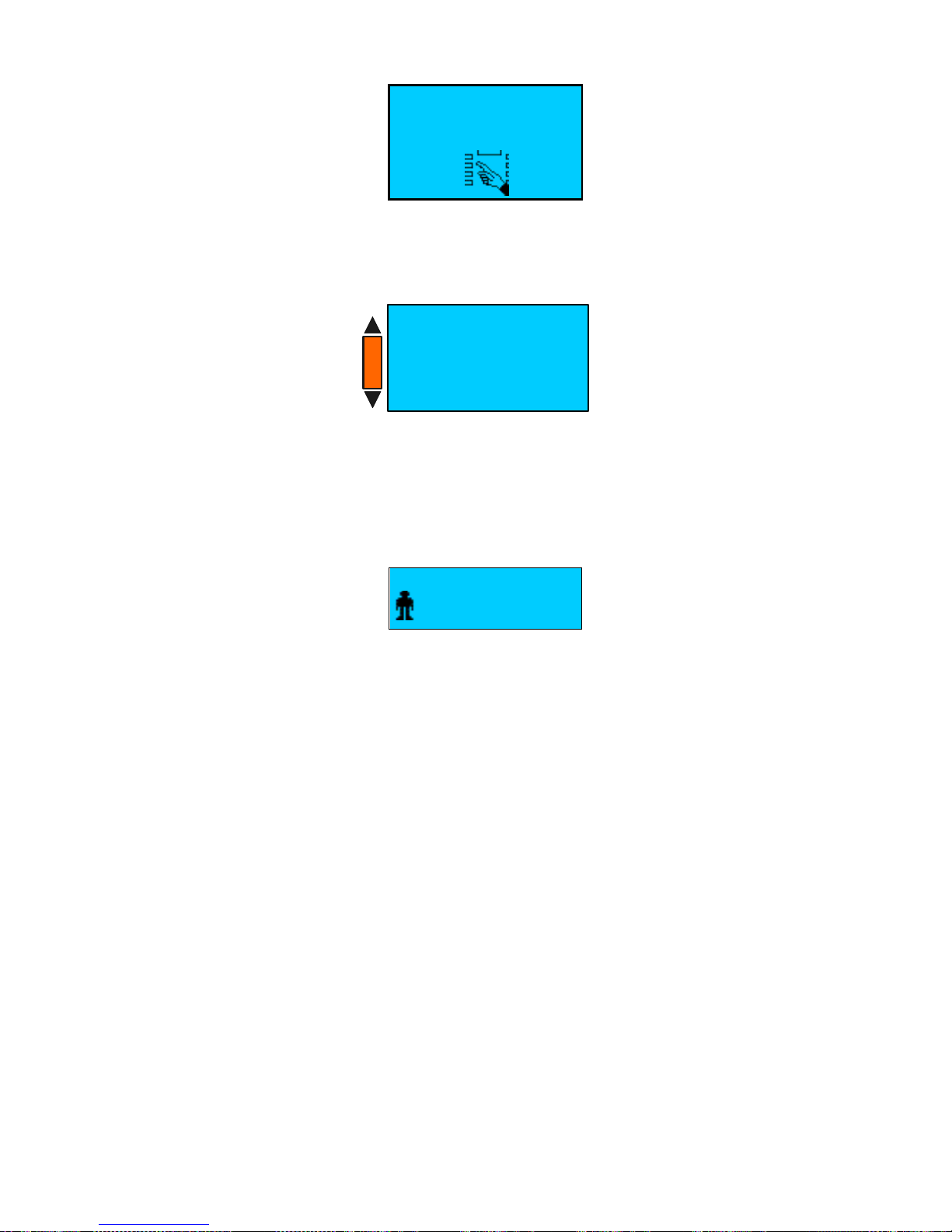
b) To switch ON the machine on every type of Self – configuration, keep key n°9 (shift) pressed and then press key n° 10
( info), the display shows:
Page 11
LB.05080.00 Pag.11 16/04/2014
After insert the password ( 61111 ) the machine goes to on.
To switch OFF the machine, open the front door or place the smart card and keep key n°9 (shift) pressed and then press
key n° 10 ( info) ; or keep key n° 9 (shift) pressed for 5 seconds, and after insert the password, the display shows:
Press the key n°6 ( + ) to select OFF and then press the key n°7 ( Enter ) to confirm.
c) In case of temporary voltage drop, the machine will be automatically turned back to the stage previous to the voltage
drop.
If the display shows:
SELECT DRINK
Steam not ready
The displayed message indicates that the set up heating temperature in the steam boiler has not been reached yet, and
therefore milk based dispensing are not enabled.
In that case wait until the boiler has reached the set up heating temperature.
INSERT PASSWORD
TO TURN ON
- - - - -
Select
- Clean
- OFF
- Read dose data
B5 - + B6
B7 Enter Esc B8
+
-
Page 12
LB.05080.00 Pag.12 16/04/2014
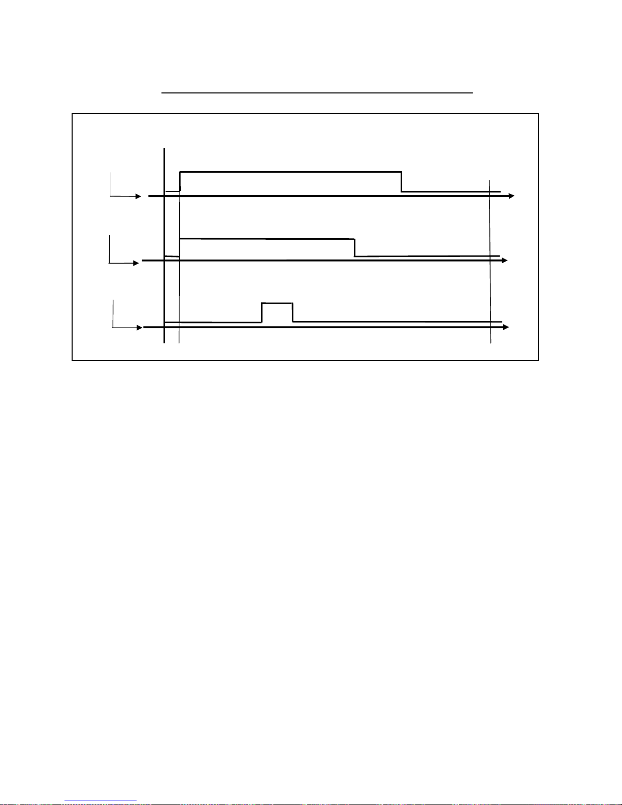
SCHEMATIC SUMMARY OF STEAM AND COFFEE BOILER HEATING PHASE
Heating element On
Temperature sensor
(
Please Wait )
Steam boiler Heating element Off
ON
Set-up ( Select Drink )
OFF
0 °C
°C
Milk frother
solenoid valve
Solenoid valve open
ON
OFF
Solenoid valve close
0 °C
95°C °C
Coffee group
solenoid valve
Rinsing phase
ON
OFF 50°C
°C
Page 13

LB.05080.00 Pag.13 16/04/2014
ACCESS THE MAIN SETTING MENUS WITH PASSWORD
A) ACCESS THE MAIN SETTING MENUS WITH PASSWORD
To enter the programming environments, a password is required which define the access rights to the different
environments.
The password must be composed with 5 numbers.
To insert the passwords proceed as follows:
- Turn the machine OFF
- Keep N°9 “SHIFT” key pressed for 5 seconds. The display shows:
Enter one of the following passwords:
- Waiter 6 1 1 1 1
- Roaster 1 1 1 1 1
- Owner 2 2 2 2 2
- Service 3 3 3 3 3
- Technician ( for Technician password contact the Carimali S.p.A. Technical Service ).
After insert the password the display shows the main menu programming environments:
KEY REFERENCE FOR PASSWORD
INSERT PASSWORD
- - - - -
Select
- Info reset
- Dose programming
- System manager
+
-
LED
1
3
5
7
2
4
6
8
Page 14
LB.05080.00 Pag.14 16/04/2014
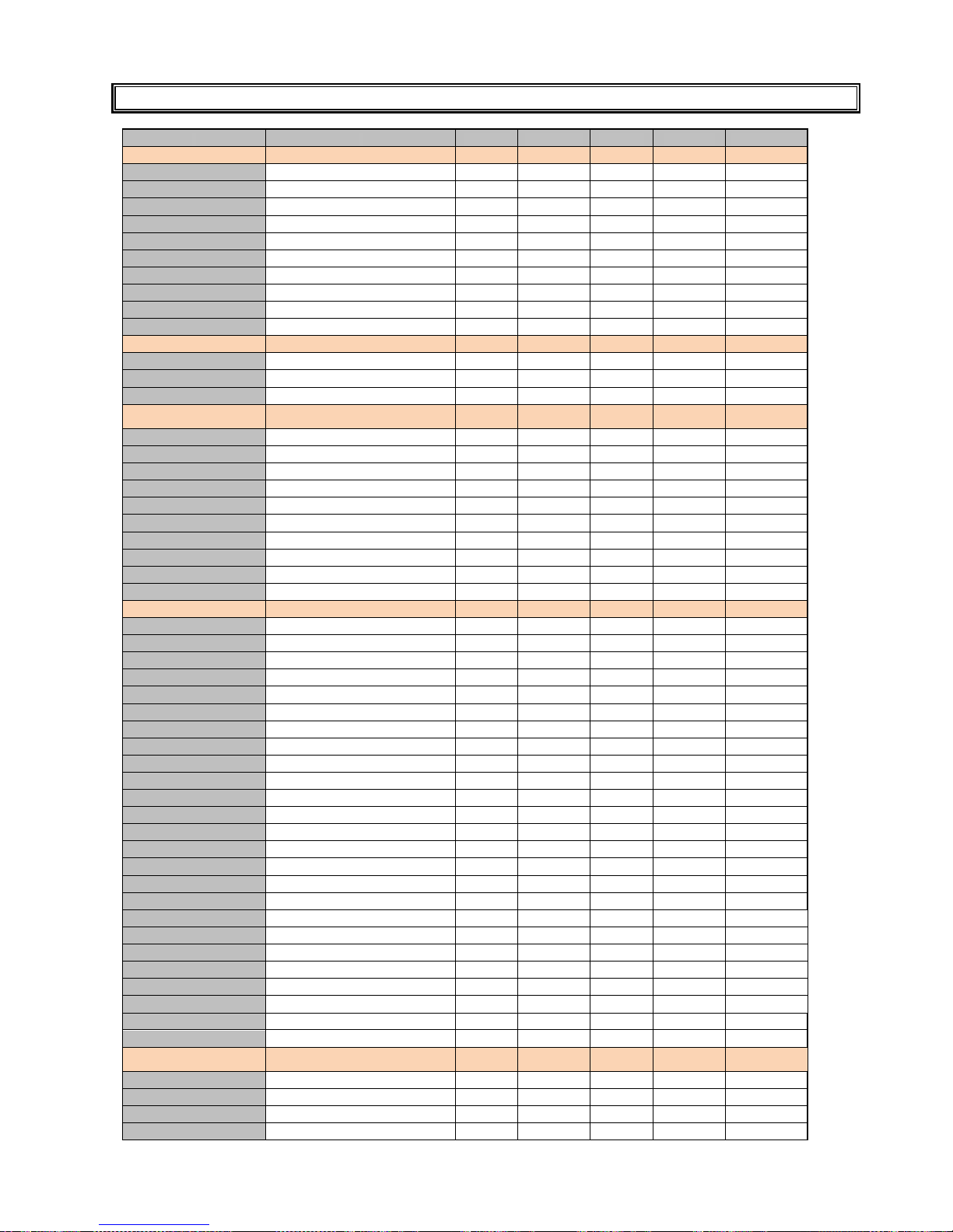
PROGRAMMABLE PARAMETERS IN ACCORDING WITH PASSWORD
WAITER ROASTER OWNER SERVICE TECHNICIAN
INFO - RESET
Reard dose data Douse counter A
X X X X X
Douse counter B
X X X X X
System data Group cleaning
X X
Milker cleaning
X X
Power cleaner
Grinder cycles
X X
Water filter
X X
Group cycles
X X
Total group cycles
X X
Total machine cycles
X X
DOSE PROGRAMMING
Set doses
X X
Price set-up
X X X
Grinder-milker calib.
X X
MACHINE
CONFIGURATION
Main power 200-400v/ 100-120v
X X
Water tank
X
Mix cold water Desabled/Enabled
X
Steam nozze Desabled/Enabled
X
Milker Desabled/Enabled
X
Milk pump Desabled/Enabled
X
Power cleaner Desabled/Enabled
X
Fridge Disable/ Enable
X
Machine type
X
Remote controller
X
MACHINE PARAMETER
Language
X X
Serial Disable/Enable
X X X
Ground N°
X X X X X
Waiting time coffee dose A-B
X
Additional coffee water
X
Rinse after milk dose
X
Waiting time milk dose A-B
X
Additional milk
X
Decimal price
X
Scale factor price
X
Multi vending
X
Token
X
Max credit on card
X
Alarm detail
X
Temp. Misure unit
X
Steam temperature
X° X° X° X X
Keyboard sound
X X
Manual clearing sound
X
Gsm: Sim card pin
X X
Gsm: Service phone number
X X
Modem set-up parameters
X X
Remote password
X X
User message
X X X X X
Serial N°
X X
Installation date
X X
SYSTEM CLOCK
PROGRAMMING
YY-MM-DD Day HH:MM
X° X° X° X X
Clock display Enable/Disable
X X X
Auto start –up Disable/ Enable
X X X
On - Off
X X X
Page 15

LB.05080.00 Pag.15 16/04/2014
Day Off
X X X
DISPLAY REGULATION
Contrast
X X X
Display mode
X X X
Default colour
X X X
Color shift menu 1
X
Color shift menu 2
X
SERVICE
Clean/Rinse Cleaning time
X X X X
Cycle cleaning alarm
X
Group cleaning Programming
X
Group auto rinsing
X X X X
Milker cleaning program.
X
Milker auto rinsing
X
Maintenance set -up
Water filter
X X
Machine service
X X
Grinders
X X
Group cycles
X X
CHANGE PASSWORD
Turn ON password
X
Roaster
X X X X
Owner
X X X
Service
X X
Technician
X
GROUP MANUAL
MOVEMENTS
Group manual movements
X X
TEST ACTUATORS
Test actuators 1-2-3
X X
Milk pump speed
X X
BOILER DRANING
Boiler draining
X X
ALARM HISTORY
Alarm history
X° X° X° X X
PRESET CONF. DATA X X
Preset configuration data
X X
Where X indicate the available program and X° indicate the partial available program.
N.B. :
A) If the “ PRESET CONFIGURATION DATA “ is done with the password will be reseted only the service accessible
parameters.
Page 16
LB.05080.00 Pag.16 16/04/2014
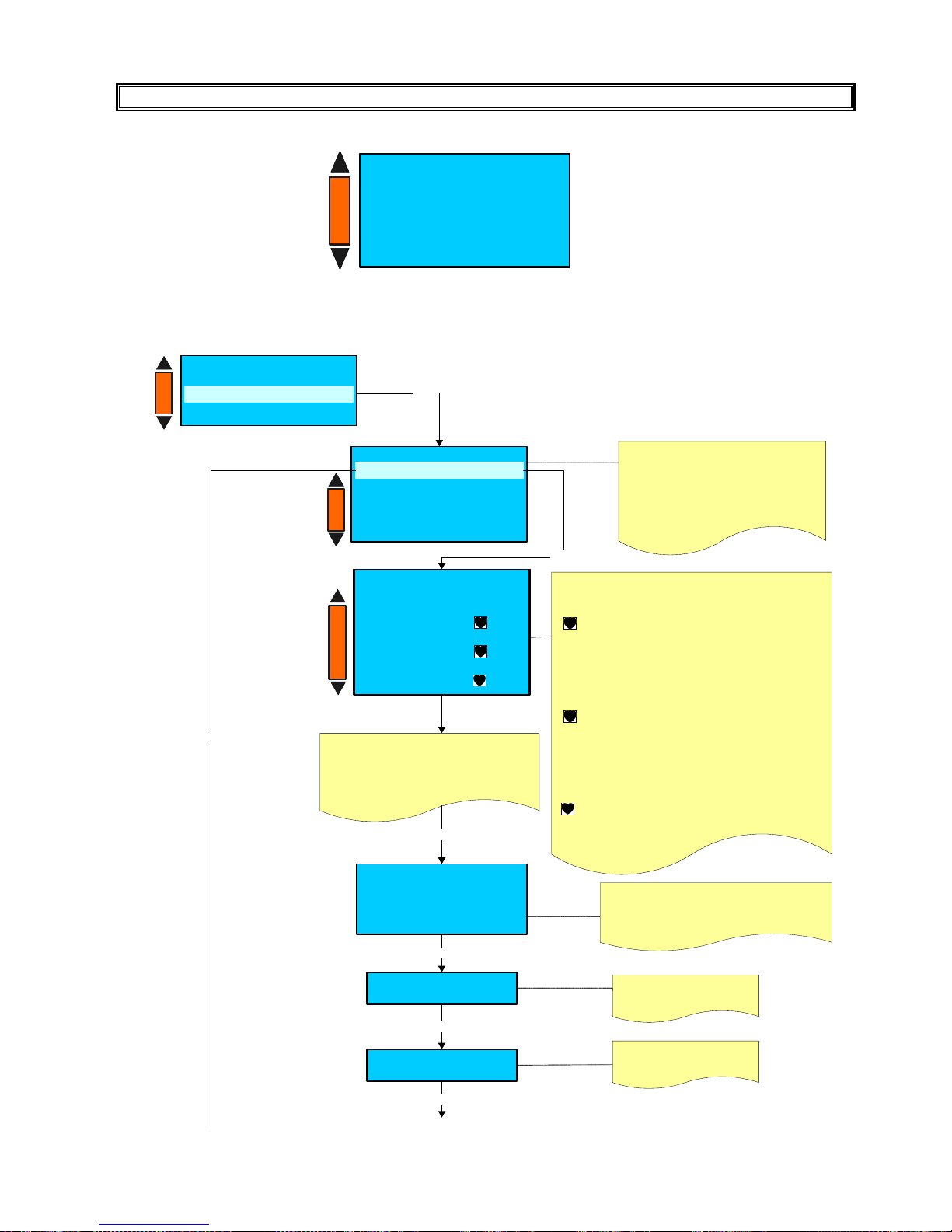
INFO-RESET
A1) READ DOSES DATA ( Doses counter A/B )
Enter
Info reset
- System data
Read doses data
Read doses data
- D oses counter B
- R eset doses counter A
- R eset doses counter B
Doses counter A
Enter
Doses counter A
BX XXXXXX
YY Y
B X² XXXXXX
ZZ Z
BX ³ XXXXXX
JJ J
Press the + / - keys to select the count A
or B.
Is possible read two counter A or B,
which can be use one for the total
number of the dispensed daily doses and
another for the total number of the
dispensed weekly or monthly doses .
BX Indicates the number of the key.
XXXXX Indicates the nam e of the selected key.
YY Indicates the number of cups dispensed
Y Indicates the number of decaffeinated
dispensed cups.
BX² XXXXX Indicates the name of the selected
key of the second dose keys menu ( SHIFT
pressed once )
ZZ Indicates the number of the cups dispensed.
Z Indicates the number of decaffeinated
dispensed cups.
BX ³ XXXXX Indicates the name of the selected
key of the third dose keys menu (SHIFT pressed
twice)
JJ Indicates the num ber of the cups
J Indicates the number of decaffeinated
dispensed cups.
Press + / - to select the keys between
B1 to B8 first dose keys menù
B1² to B8² second dose keys menù
B1³ to B8³ third dose keys menù
Group cleaning
X
X : Indicates the n° of Extra
milk carried out
Extra milk
X
Enter
X : Indicates the n° of Group
cleaning carried out
Enter
Total Dose Y
X
Last reset
YYYY - M M - DD - HH:MM
Y: Indicates the couter A o B
X : Indicates the total dose delivered
YYYY - MM - DD - HH:MM
: Indicates the
date and time of the last reset doses counter.
Enter
Enter
Enter
+
-
+
-
+
-
Info reset
- Read doses data
- System data
+
-
Page 17

LB.05080.00 Pag.17 16/04/2014
A2) READ DOSES DATA ( Reset doses counter A/B )
En ter
In fo res et
- S yste m d a ta
R ea d d os es d ata
R ead d ose s d ata
- D os es c o un ter A
- D os es c o un ter B
- R es et d ose s c ou nte r B
R e se t D o ses c o un te r A
W IT H T H IS O P ER A T IO N W E
R ES ET O N LY TH E D O SE S
C OU N T – E XT RA M IL K A N D
TO T AL C A SH IN G
+ / -
N o
Y e s
En ter
R ese t D ose s C ou nter
P le ase co nfirm
R ese t D ose s C ou nter
Pre s s the + / - ke y s to se le c t
th e co u nt A o r B .
E n ter
E n ter
+
-
+
-
Page 18
LB.05080.00 Pag.18 16/04/2014
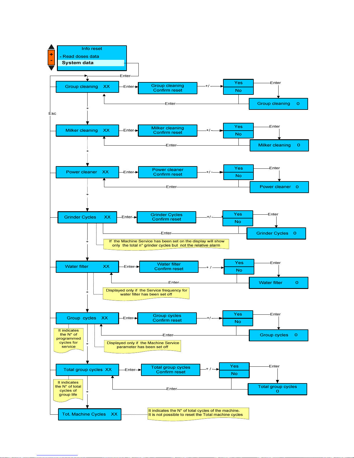
B) INFO RESET SYSTEM DATA
Page 19
LB.05080.00 Pag.19 16/04/2014
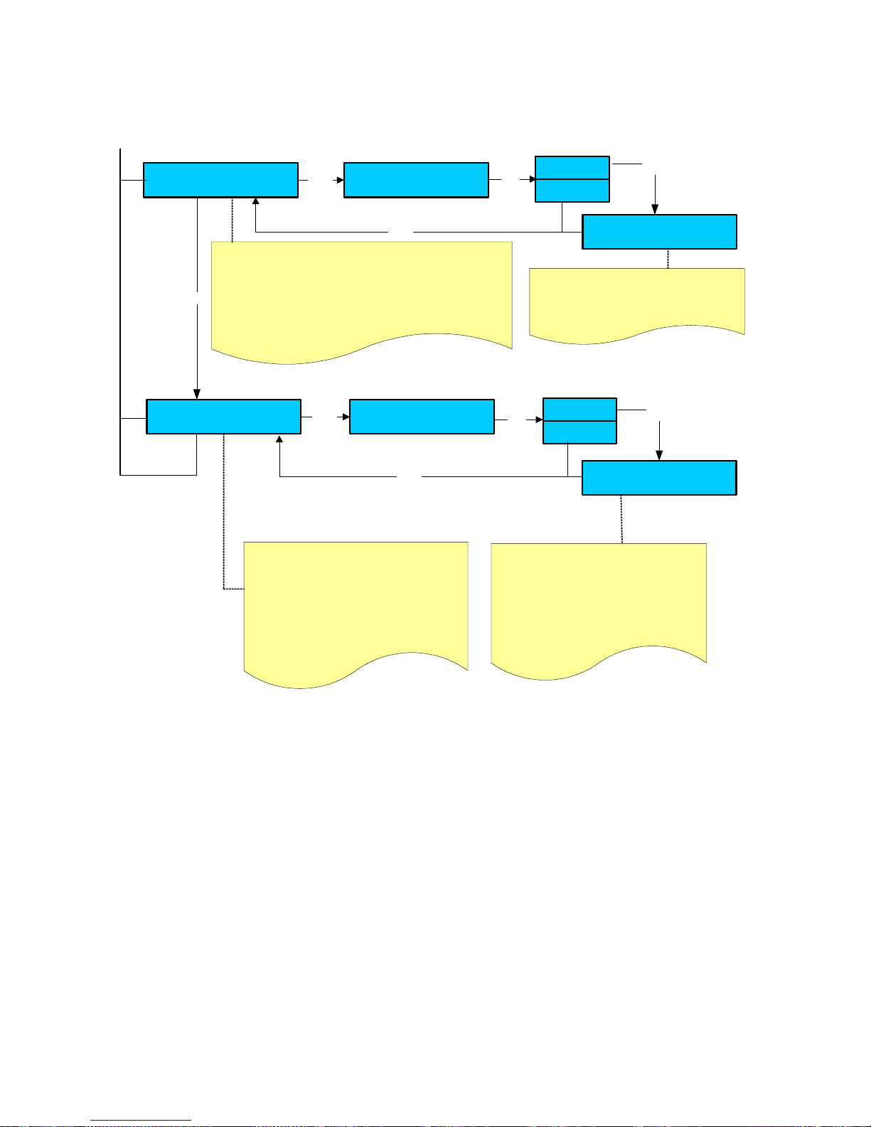
THE FOLLOWING INFO ARE DISPLAYED ONLY WHEN THE CLOCK IS PROGRAMMED
Machine service
XXXX YY - ZZZZ
XXXX : Indicates the n° of group cycles left. If
the programmed n° of group cycles exceed the
display shows: ( - XXXX )
YY : Indicates the maintenance month
ZZZZ : Indicates the maintenace year
If the service alarm elapses within one month
or if the 90% of the set number of group cycles
has reached, this parameter can be reset
Machine service
Confirm reset
Enter
Machine service
XXXX YY - ZZZZ
+ / -
XXXX : Indicates the n° of group cycles
programmed.
YY : Indicates the next maintenance month
ZZZZ : Indicates the next maintenace year
N.B.: WITH THE MACHINE SERVICE
RESET WILL BE ERASE ALSO THE
CLEANING GROUP AND MILKER TOTAL
NUMBER.
Yes
No
Enter
Enter
Water filter
XXXX YY - ZZZZ
XXXX : Indicates the n° of water filter liters left. If the
programmed n° of of water filter liters exceed the display
shows: ( - XXXX )
YY : Indicates the maintenance month
ZZZZ : Indicates the maintenace year
If the water filter alarm elapses within one month or if the 90%
of the set number of liters has reached, this parameter can be
reset
Water filter
Confirm reset
Enter
XXXX : Indicates the n° of water filter liters
programmed.
YY : Indicates the next maintenance month
ZZZZ : Indicates the next maintenace year
Yes
No
Water filter
XXXX YY - ZZZZ
Enter
+
+ / -
Enter
WARNING:
The owner’s password can only enter total dose reset environment and water softener alarm reset.
Environments: group cycles, M1 tools time, water filter litres will be displayed only if values higher than 000 (zero) have been
set during the programming stage.
Page 20
LB.05080.00 Pag.20 16/04/2014
DOSES PROGRAMMING
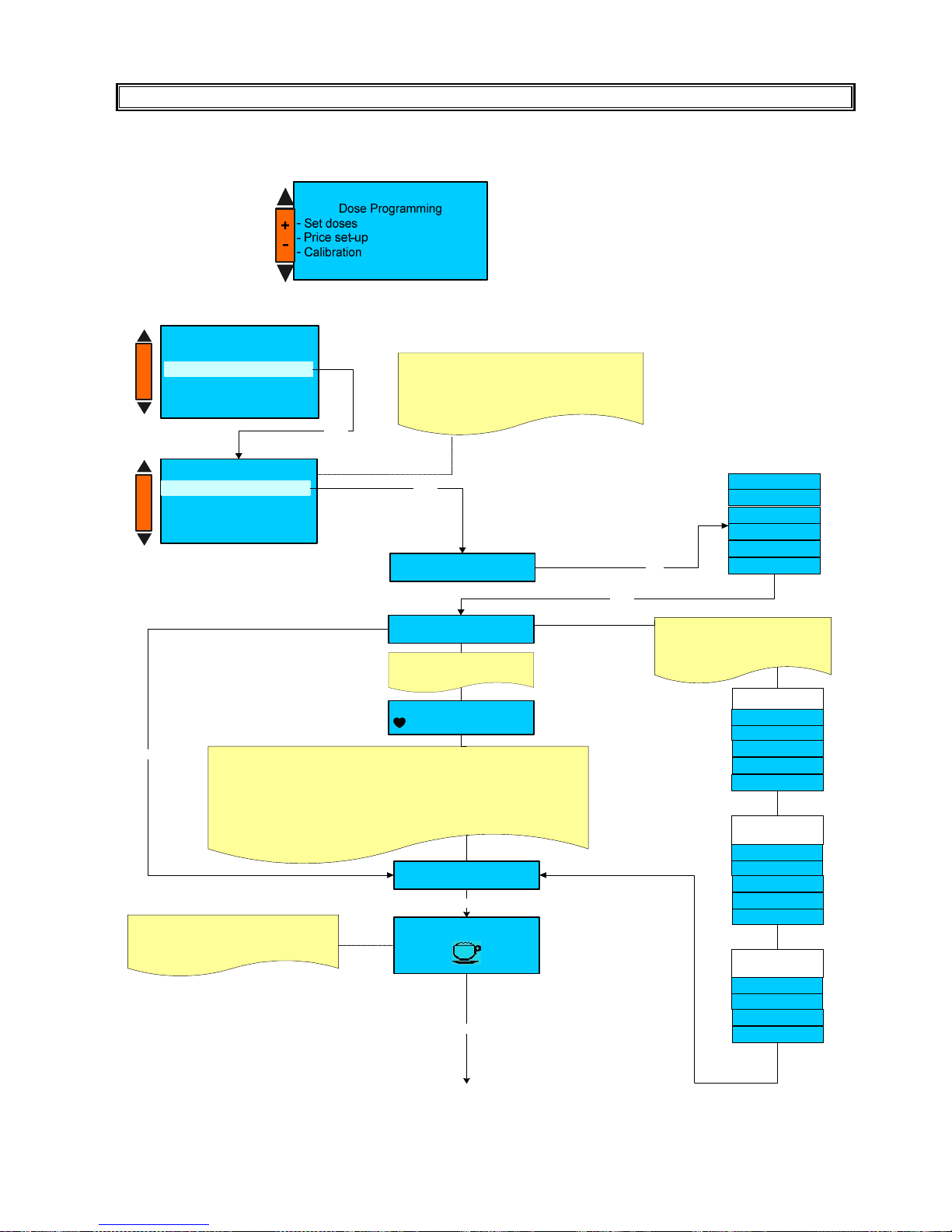
PLEASE NOTE :TO ACCESS TO THE DOSES PROGRAMMING THE MACHINE MUST BE AT THE SET-UP TEMPERATURE.
Press the key N° 5 (-) and N° 6 (+) to select the parameter and then press the key 7(Enter) to confirm the selection.
A) SET DOSES
Coffee
M ilk
Hot W ater
Disable
BX D rink type
+ / -
BX D rink nam e
XXXX X
Enter
To m o dify the drink nam e
press the key B 1 .
the dis play show
XX X XX
-B-C-D-F-G -H-I-L-M -
The heart sym bol (cursor) must be lo cate d on th e ch a racter you w a nt to select .
To scroll the chara cter use the keys (+ / - ).
Pre ss E n ter key to confirm the selection .
Use key B 1 to sk ip at th e en d of the nam e .
Use key B 2 to de lete a le tter.
Use key B 3 to insert a sp ace .
After y o u se lected the re quired n am e, press Enter key, the d isplay shows :
TX D rink nam e
XXXX X
Enter
Coffee + Milk
Enter
Black coffee
Kaffe e
Americano
Coffee
Esp resso
Based on the s elected drink typ e ,
the relevant d rin k na m e w ill be
show n .
Press + /- to select the drink nam e
from the d e fault names list.
COFFEE B A S E D
DRIN K N A M E
La tte m acchiato
Milchka ffee
Caffè latte
Cappu ccin o
Esp . m acchiato
COFFEE + M ILK
BASED D RIN K
NAM E
Enter
T X Select icon
Pre ss + /- to select the ic o n which w ill be
displayed during dispensing .
Dose P rogramm ing
- Price s et-up
- Calibration
Set do s e s
Enter
Set doses
BX X X XX XX X XX
BX X X XX XX X XX
BX X X XX XX X XX
BX X X XX XX X XX
BX X XX X XX XX X
Enter
+
-
+
-
BX
= Selected n° key of the first d o se k e ys m enù
XXXX XX
= k e y na m e.
BX
²
= S electe d n°key of th e s e cond dose ke ys m enù
BX
³
= S electe d n°key of th e thir d do se keys menù
Milch
Le c he
Milk
La tte
MIL K BASE D
DRIN K N A M E
Steam
Page 21
LB.05080.00 Pag.21 16/04/2014
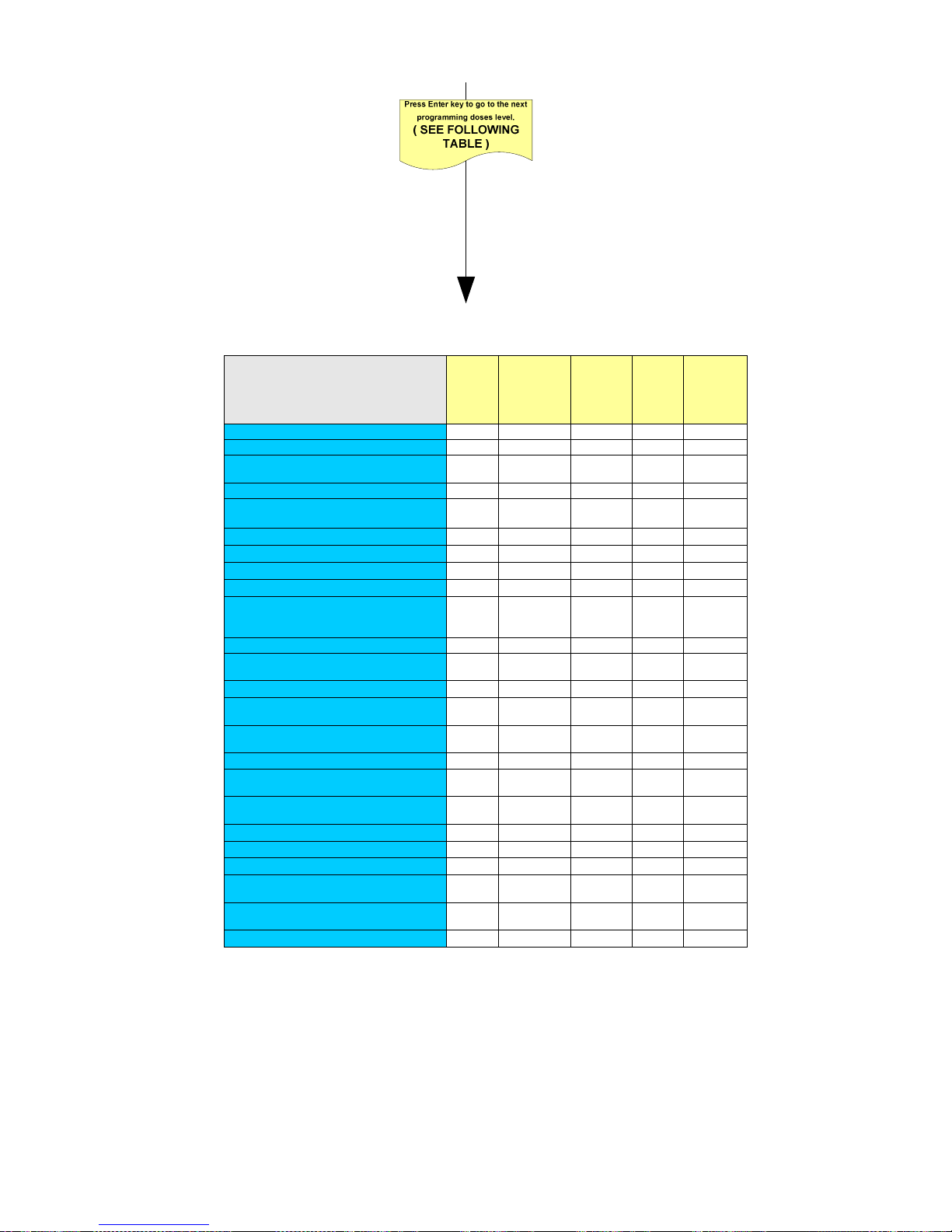
Depending on the drink type, the necessary dose parameters will be activated to set the drink.
Press the key N°7 (Enter) to confirm the modification carried out and shift to the next level.
Press the key No 5 (+) and No 6 (-) to modify the level mode.
Press the key N° 8 ( Esc) to return to the previous environment and/or exit.
Please note:
A) Some dose parameters will be displayed only if the relevant component has been activated in the “MACHINE PARAMETERS”
environments : milker- interface i/o hartwall or coin mechanism.
B) For Coffee + Milk and Milk drink type the “repetition cycle “is not available.
C) The “Milk pump speed and Cold milk parameters” will be displayed only for machine with the milk pump installed.
DOSE
PARAMETERS
Coffee
Drink
type
Coffee+
Milk Drink
type
Milk
Drink
type
Steam
drink
type
Hot
Water
drink
type
DECAFFEINATED Enabled/Disabled
X X - - -
GRIND TIME G1
X X - - -
PRE-INFUSION
XX
PAUSE XX sec.
X X - - -
COFFEE WATER VOLUME XX
X X - - X
EXTRA WATER XX
START AFTER XX
X X - - -
BOILER TEMPERATURE
X X - - -
START COLD WATER cc.
X X - - -
COLD WATER ml. ON
X X - - -
COLD WATER ml. OFF
X X - - -
COFFEE CAKE DECOMP.
10 = 0.5mm.
- XX Puls.
X
X
-
-
-
REPETITION CYCLE
X - - - -
COLD MILK
xx sec.
MILK PUMP SPEED Xx %
- X X - -
EXTRA MILK Enabled/Disabled
- X X - -
STEAM MILK PRE sec
MILK PUMP SPEED Xx %
- X X - -
FOAMED MILK PRE sec
MILK PUMP SPEED Xx %
- X X - -
PAUSE MILK-COFFEE se
- X X - -
STEAM MILK POST sec
MILK PUMP SPEED Xx %
- X X - -
FOAMED MILK POST sec
MILK PUMP SPEED Xx %
- X X - -
CODE I/O
X X X X X
CODE I/O EXTRA-MILK
- X X - -
STEAM TIME
- - - X -
PURGE AFTER STEAM
PAUSE XX.Sec
- - - X -
PURGE AFTER STEAM
PURGE XX.Sec.
- - - X -
DELIVERY TEST
X X X - -
Page 22
LB.05080.00 Pag.22 16/04/2014
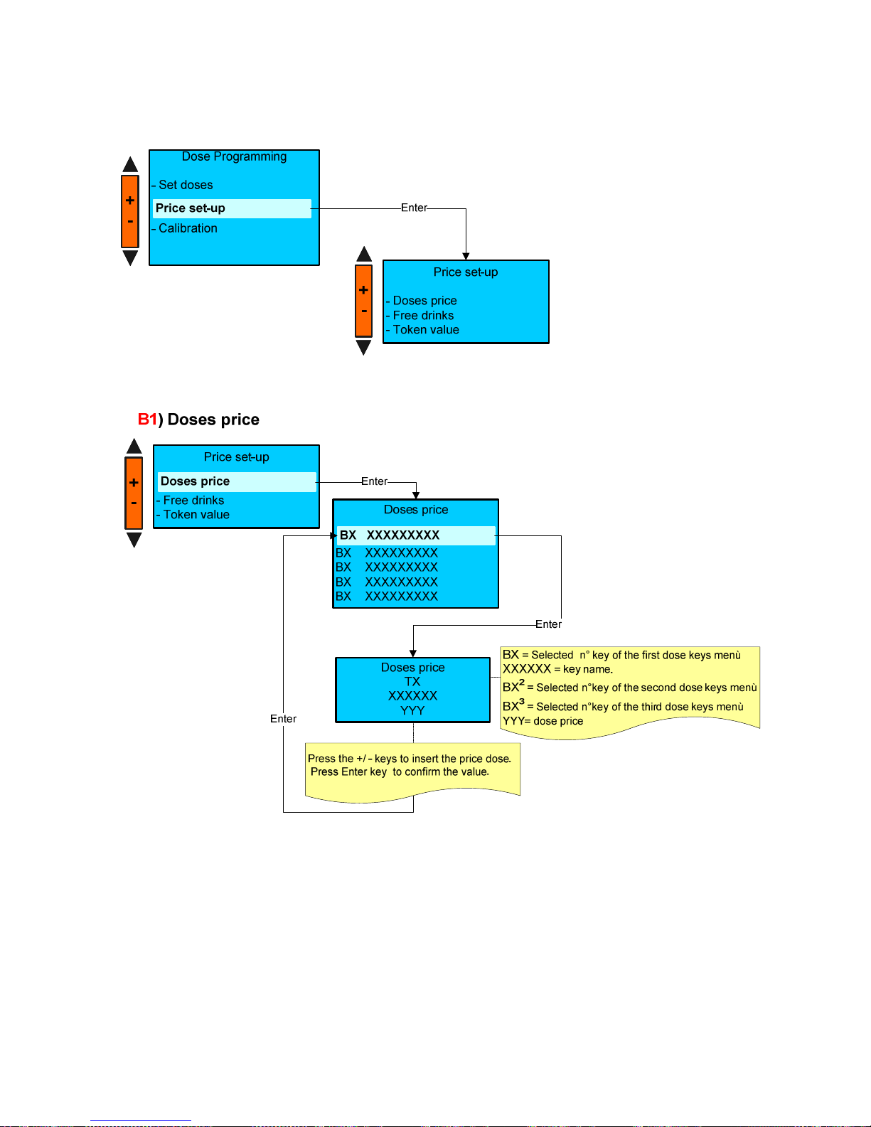
B ) PRICE SET-UP
Page 23
LB.05080.00 Pag.23 16/04/2014
Price set-up
- Doses price
- Token value
Free drinks
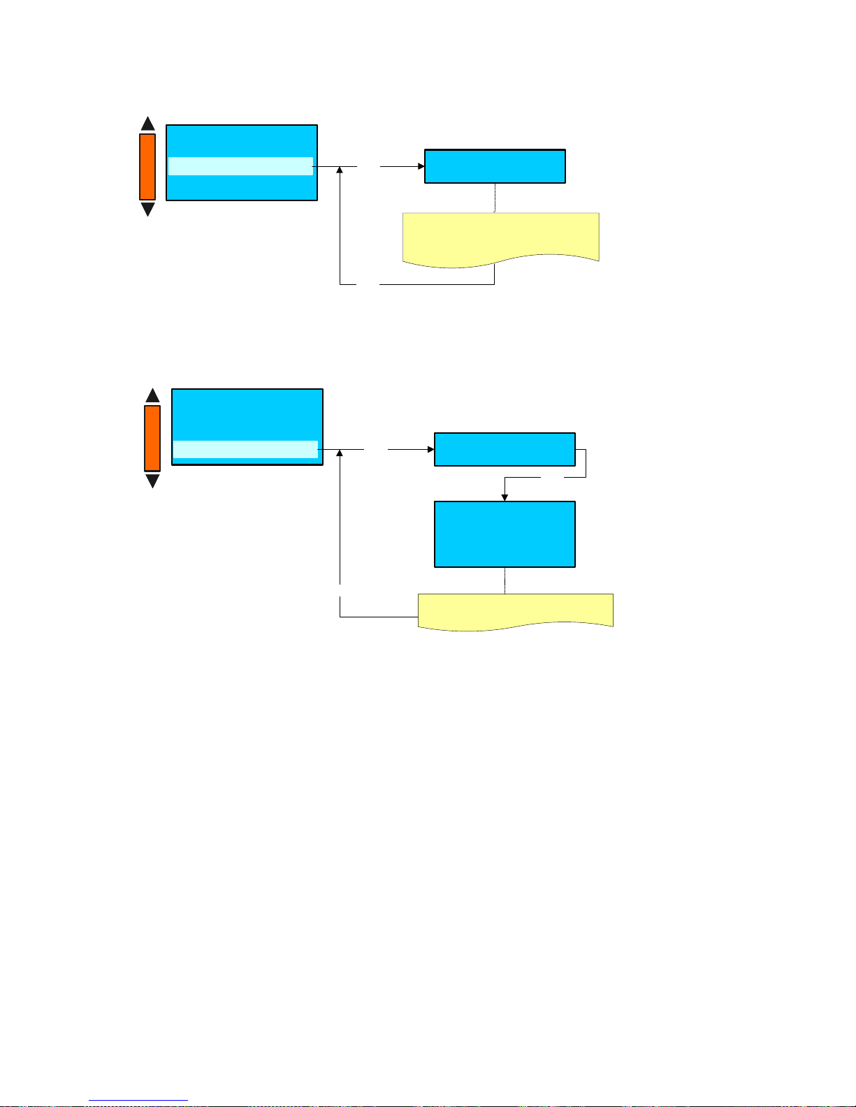
B2) Free drinks
Free drinks
Desable
Enter
Press the +/ - keys to insert Enable or
Desable the Free drink.
Enter
Price set-up
- Doses price
- Free drinks
Token value
B3) Token value
Enter
Token value
A : x.xx
B : x.xx
C : x.xx
Press the +/ - keys to insert the token price
Press Enter key to confirm the value.
Price set-up
Token value
Enter
Enter
+
-
+
-
Page 24
LB.05080.00 Pag.24 16/04/2014
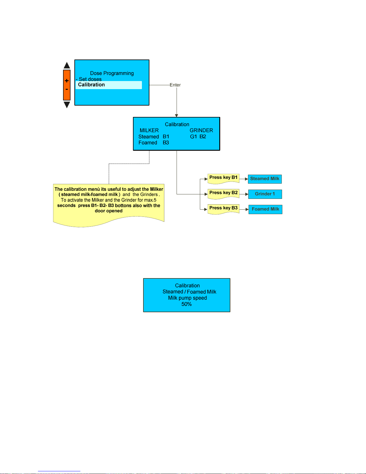
C ) CALIBRATION ( Grinder-Milker )
WARNING:
If milk pump enabled , it is possible to set the pump speed by pressing +/- buttons during the delivery, the display shows :
the set value will be saved in all drinks with steamed foamed milk.
Page 25
LB.05080.00 Pag.25 16/04/2014
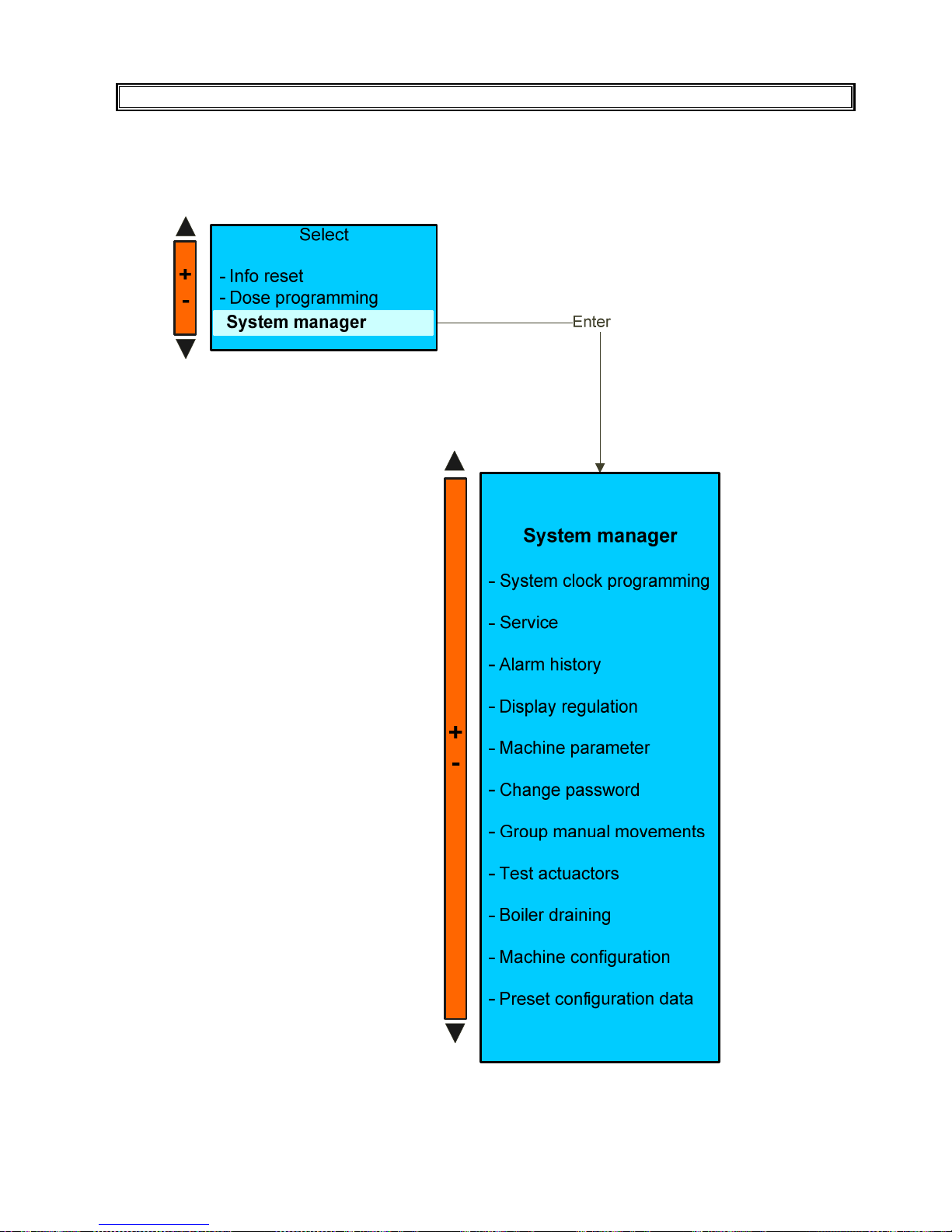
SYSTEM MANAGER
Press the key N° 7 (Enter) to confirm entering the desired environment.
Press the key N° 8 (Esc) to exit.
Page 26
LB.05080.00 Pag.26 16/04/2014
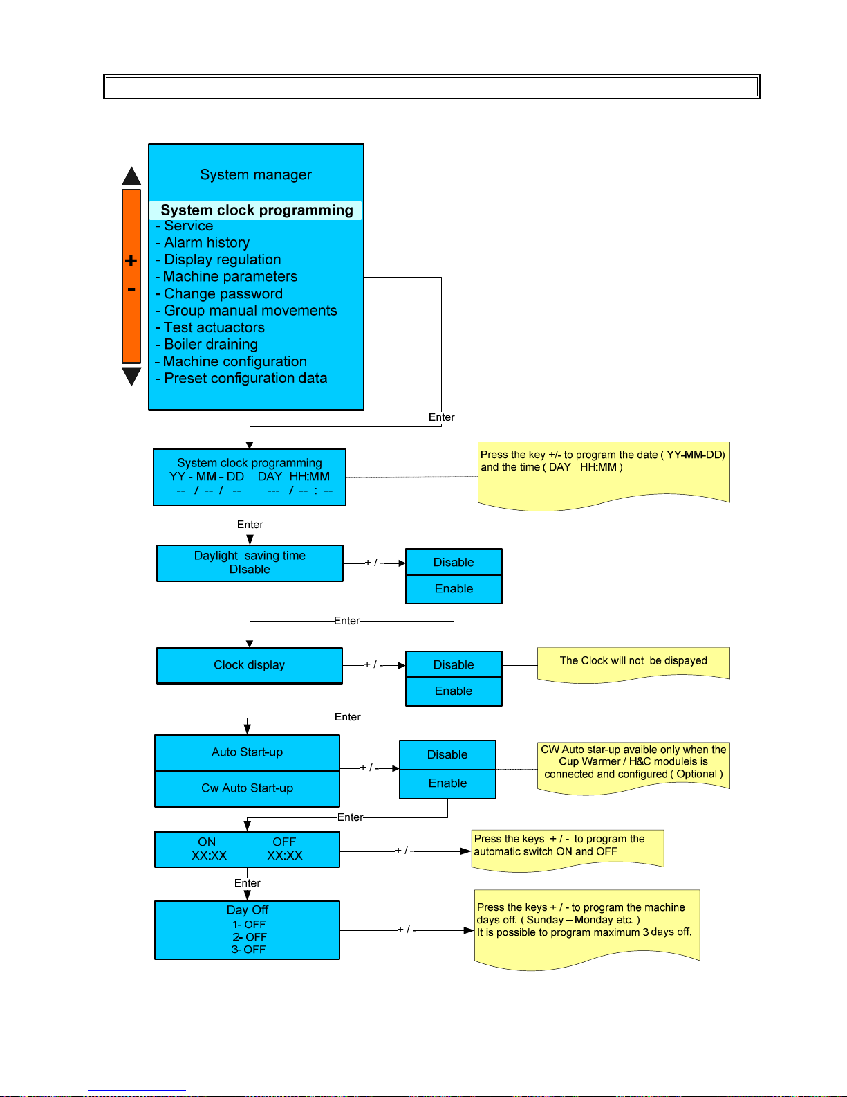
SYSTEM CLOCK SET-UP
Page 27
LB.05080.00 Pag.27 16/04/2014
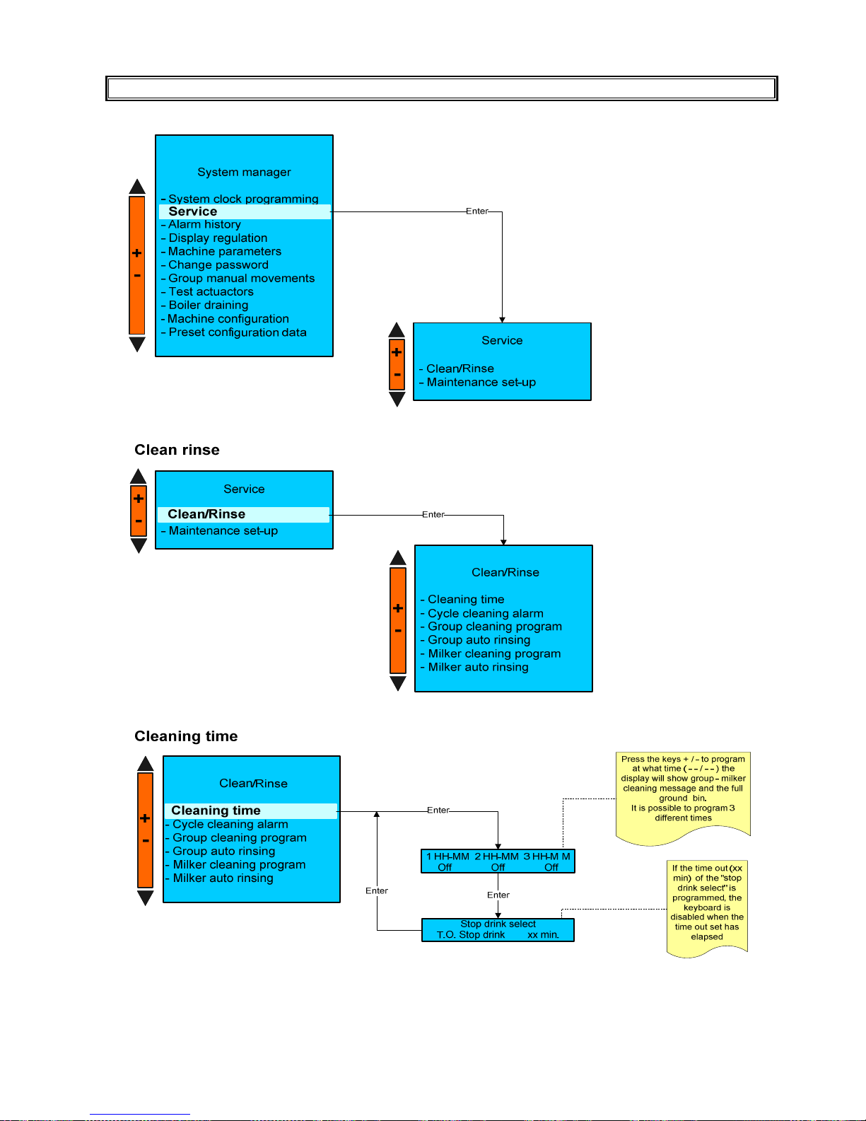
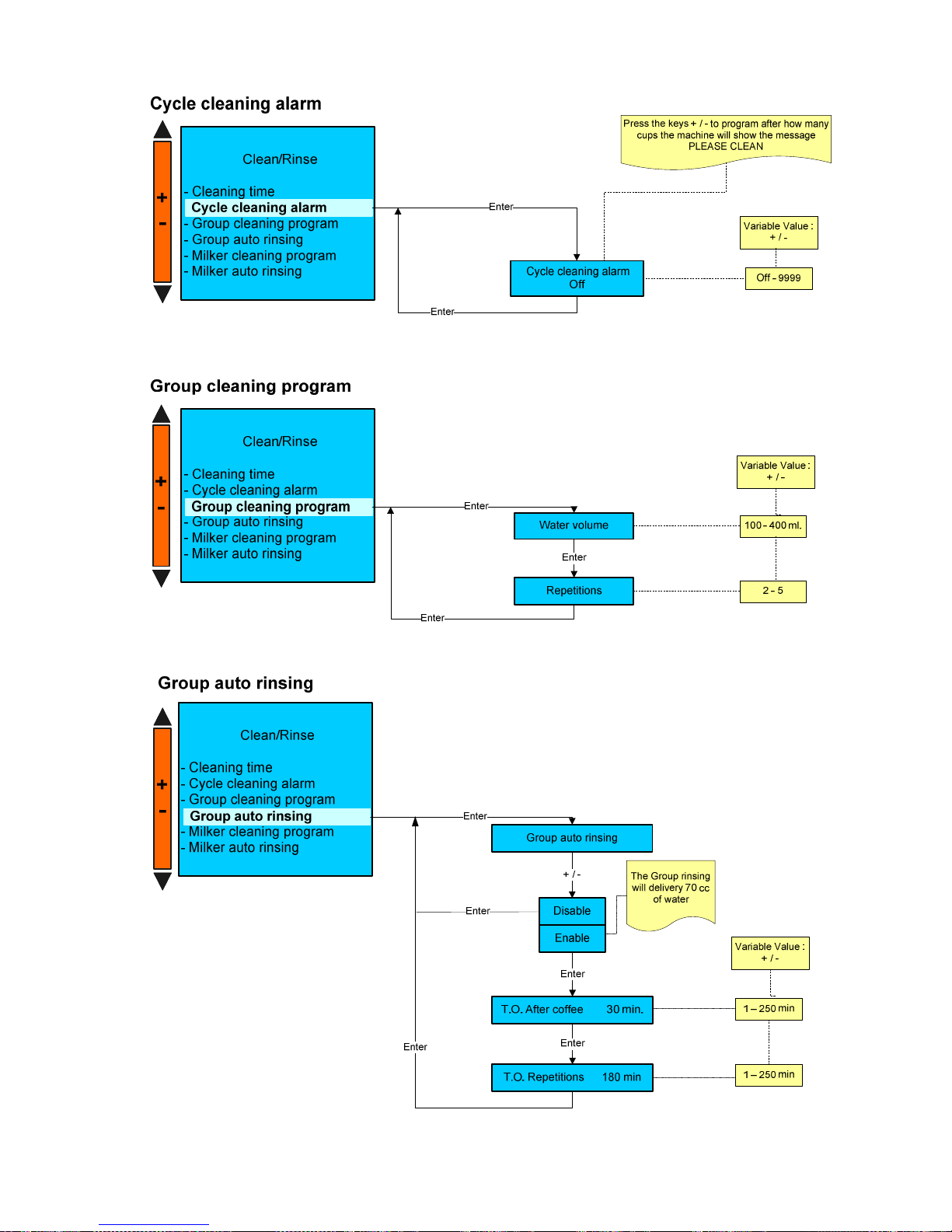
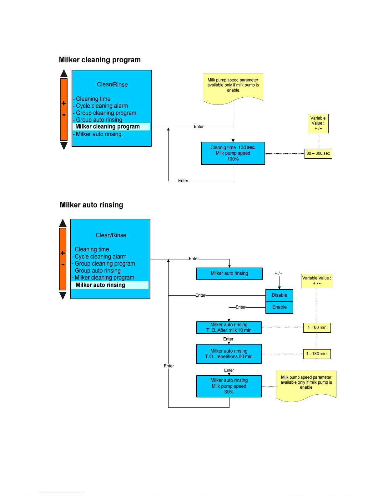
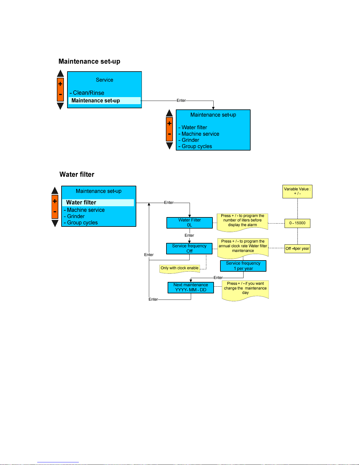
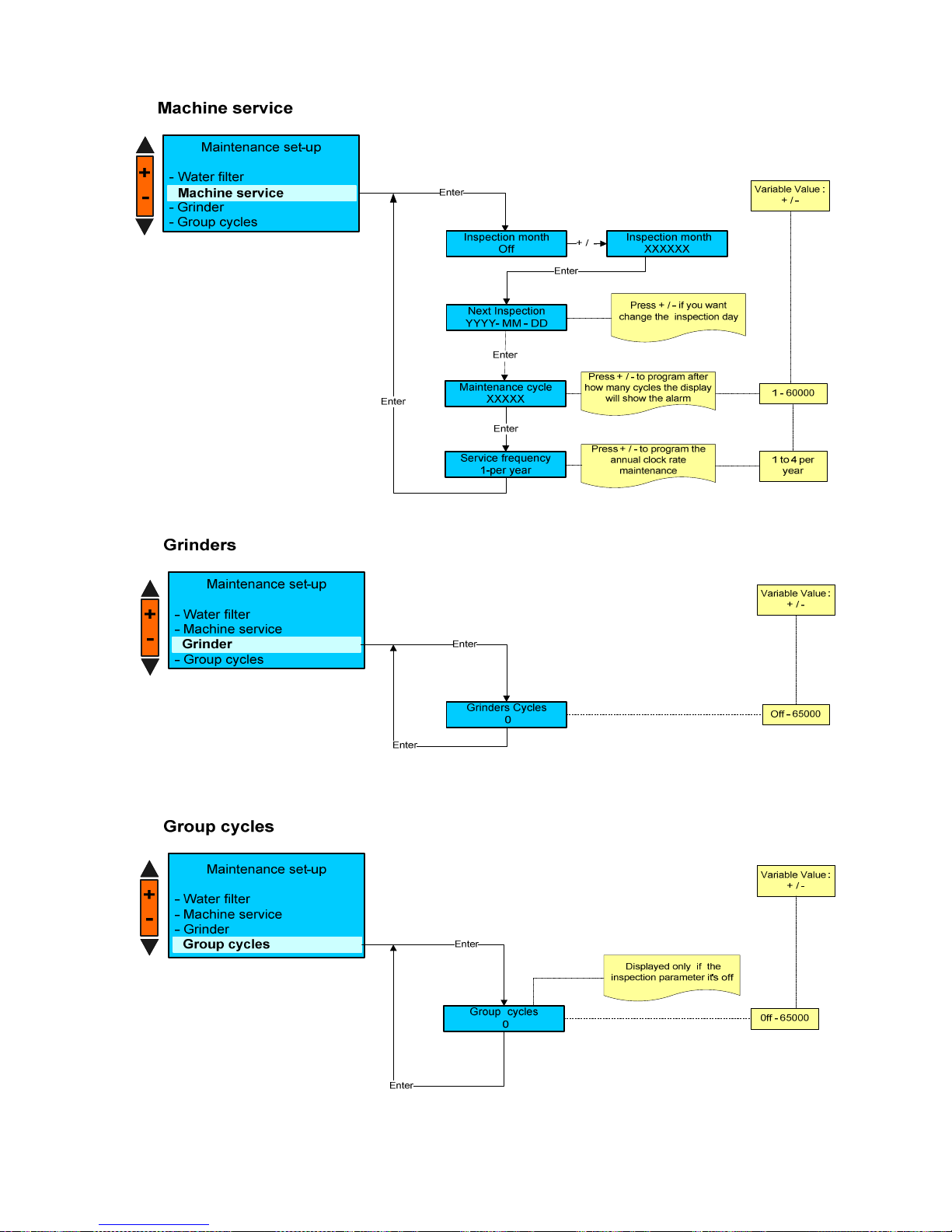
SERVICE
Page 28
LB.05080.00 Pag.28 16/04/2014
Page 29
LB.05080.00 Pag.29 16/04/2014
Page 30
LB.05080.00 Pag.30 16/04/2014
Page 31
LB.05080.00 Pag.31 16/04/2014
Page 32
LB.05080.00 Pag.32 16/04/2014
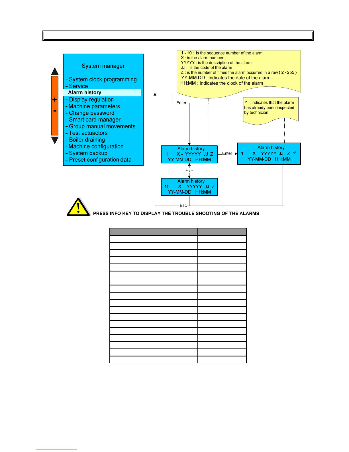
ALARM HISTORY
Please Note:
a) The maximum alarm number the machine can save is 10.
b) To reset the alarm data memory, carry out “Preset Configuration Data” procedure.
Press the N°7 Enter key to return to the previous environment and/or exit
ALARM DETAILS
ALARM CODE
NO H. MOTOR PULS
10
NO L. MOTOR PULS
11
H. MOTOR ERROR
12
L. MOTOR ERROR
13
FILLING UP T.O.
32
STEAM HEAT T.O.
34
CHECK FLOW LINE
35
STEAM TEMPERATURE
38
INFUSION T.O.
41
CORRUPTED DATA
60
CLOCK ERROR
63
MOTOR BLOCK
65
COIN VALIDATOR ERROR
70
CHANGE H2O FILTER
90
GROUP MAINTENA
NCE
91
GRINDER MAINTENANCE
93
TOO MUCH COFFEE
15
MAINTENANCE
92
Page 33
LB.05080.00 Pag.33 16/04/2014
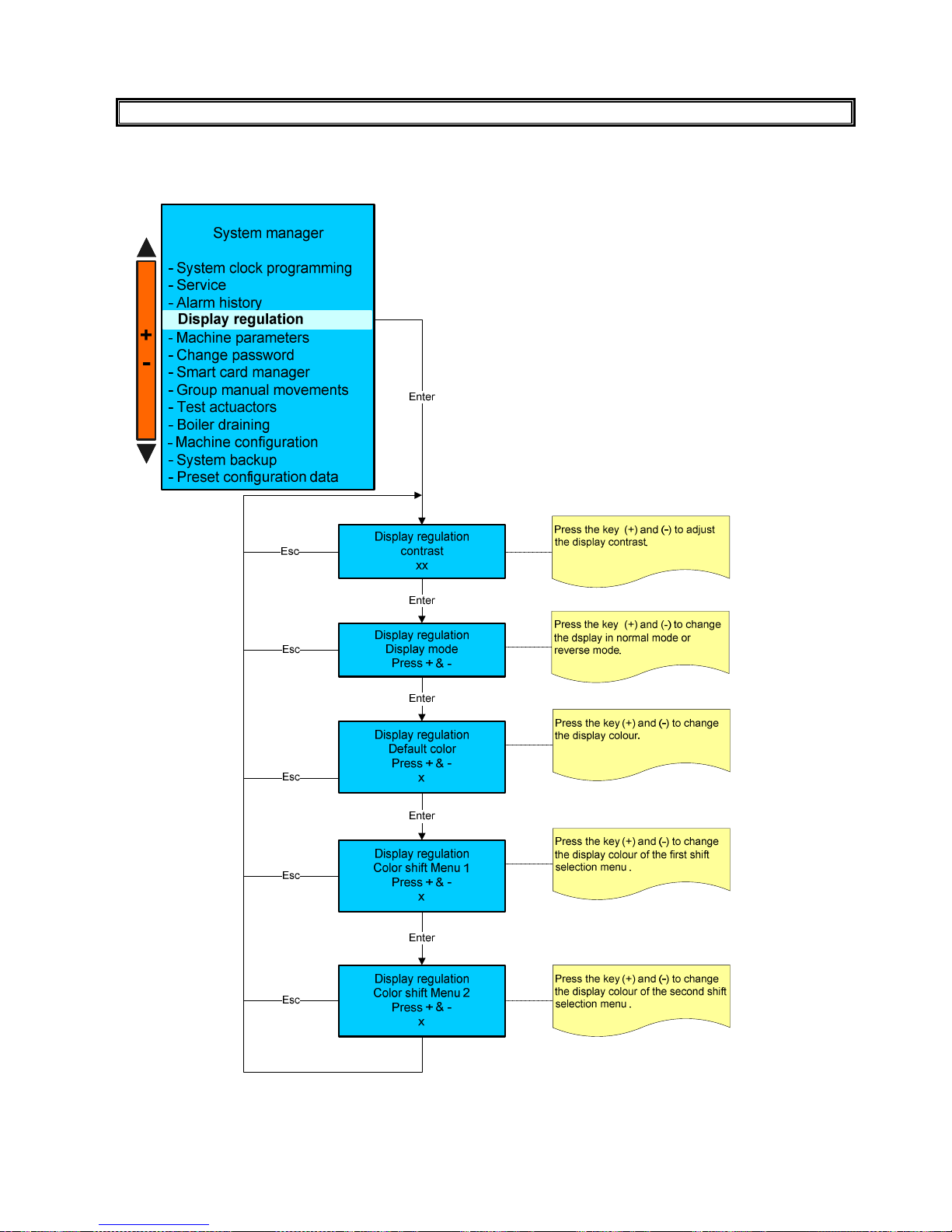
DISPLAY REGULATION
Page 34
LB.05080.00 Pag.34 16/04/2014
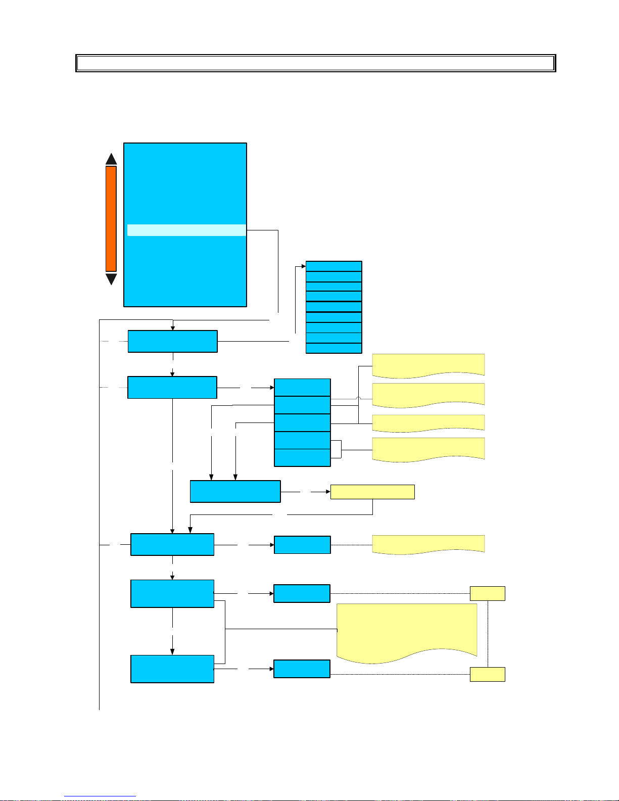
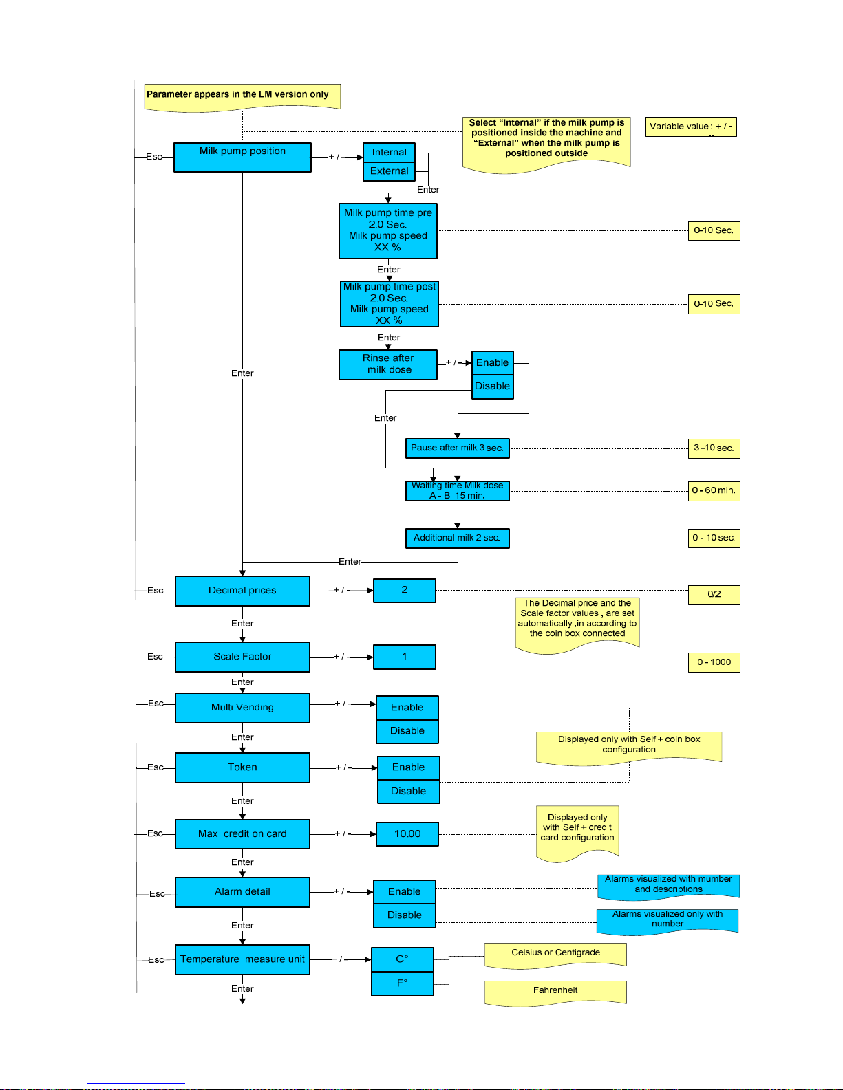
MACHINE PARAMETERS
PLEASE NOTE :
some of the following parameters may not be displayed depending to the machine configuration previously
programmed.
Language
+ / -
Enter
English
Enter
Serial
Disable
+ / -
I/O Hartwall
I/O 9600
RM5 Coin box
For I/O 18 - 26 Relais
or PC cable 1200 Baud rate
For PC cable 9600 Baud rate
Decimal price and scale factor price
must be set
In dose program menu will be activated
the relevant parameters
Enter
Esc
MDB
DEVICE
Grounds Numbers
30
+ / -
Variable Value : 0 to 100
Enter
Enter
Recive time-out
0,500 m.sec
Enter
0.020 msec. / 5 000 msec+ / -
Enter
Esc
Esc
System manager
- System clock programming
- Service
- Alarm history
- Display regulation
- Change password
- Group manual movements
- Test actuactors
- Boiler draining
- Machine configuration
- Preset configuration data
Machine parameter
+
-
German
French
Dutch
Japanese
Italian
Polish
Norwegian
Danish
Waiting time
Coffee dose A-B
Xx min.
Enter
Additional coffee water
Xx ml.
2ml.
+ / -
10min.
+ / -
0-60min.
1-50ml.
With these two parameters it is possible to set an
additional water amount for the first coffee
dispensed after a settable time out (default
values are respectively 10minutes and 2ml).
Time out starts after a coffee dispensing, a group
rinsing or cleaning cycle.
Page 35
LB.05080.00 Pag.35 16/04/2014
Page 36
LB.05080.00 Pag.36 16/04/2014
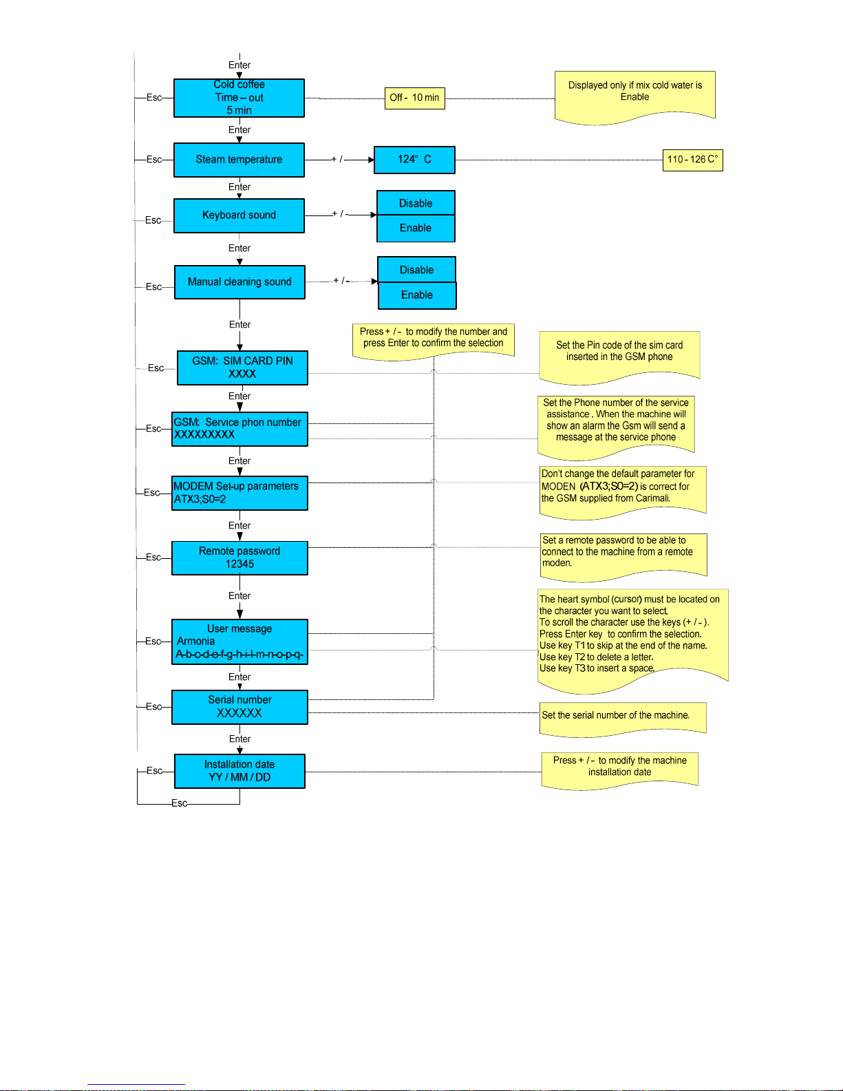
Please note: for machines without GSM it is possible to carry out a Local data download by setting the Serial number and the
Remote password only. ( For more information see the Wizard manual
Page 37
LB.05080.00 Pag.37 16/04/2014
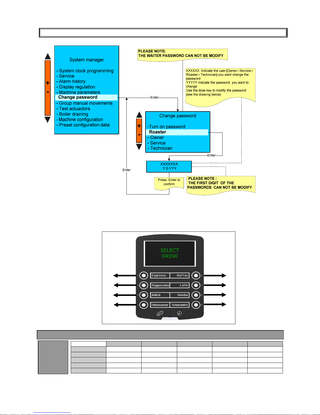
CHANGE PASSWORD
Please note :
If the TURN ON PASSWORD is enabled , to turn on the machine is necessary insert the password.
KEY REFERENCE FOR PASSWORD
Waiter
Roaster
Owner
Service
Technician
Waiter
Roaster
X
Owner
X X
Service
X X X
Technician
X X X X
Entered
Password
Following Password can be modify
1
3
5
7
2
4
6
8
Page 38
LB.05080.00 Pag.38 16/04/2014
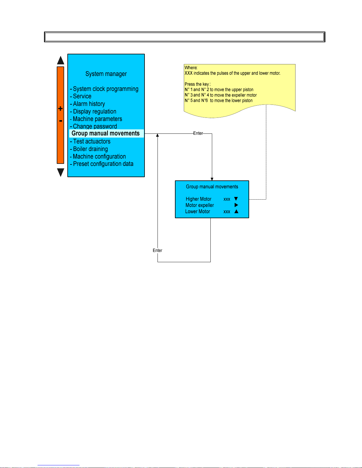
GROUP MANUAL MOVEMENTS
Page 39
LB.05080.00 Pag.39 16/04/2014
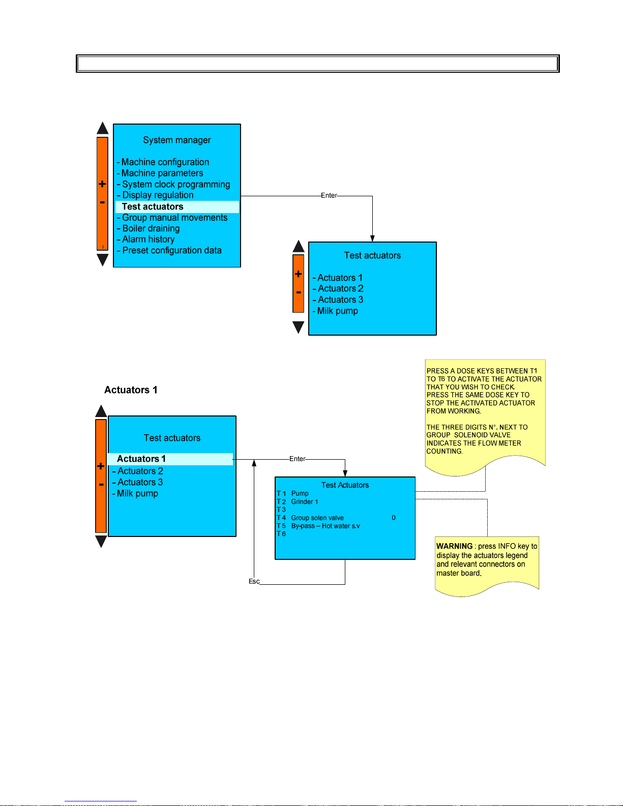
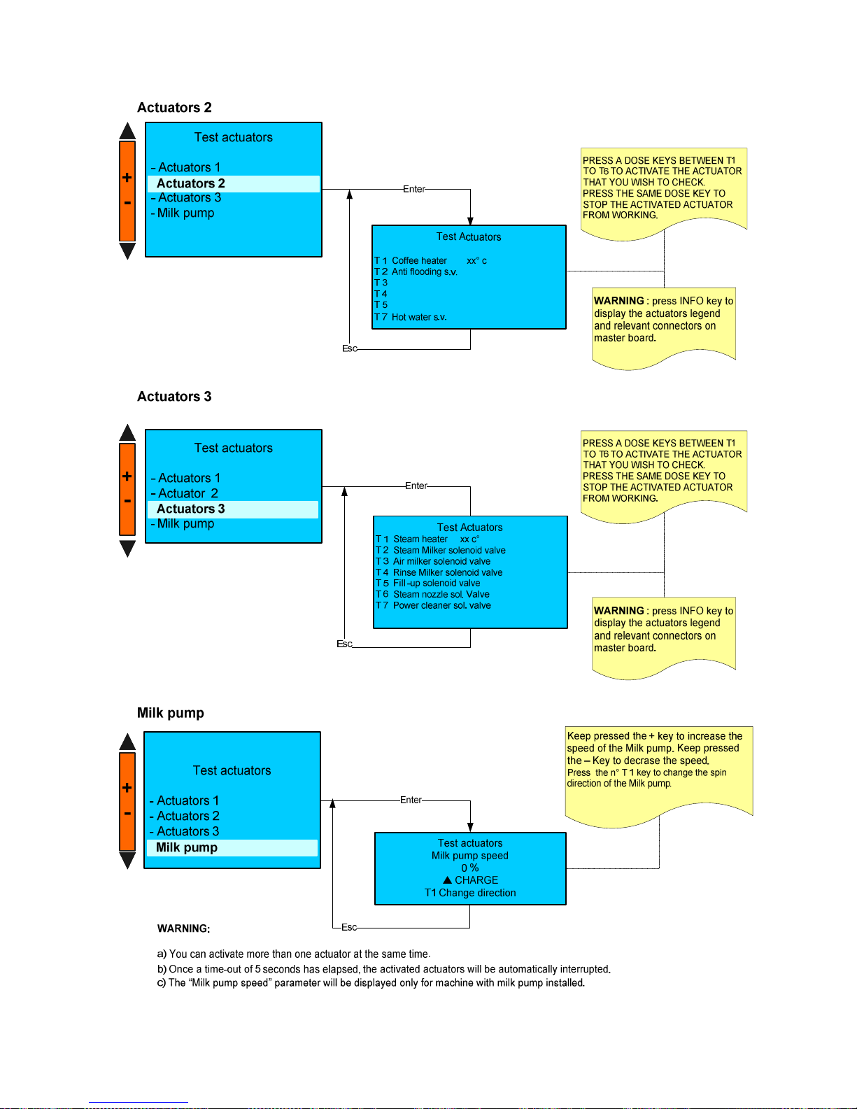
TEST ACTUATORS
Page 40
LB.05080.00 Pag.40 16/04/2014
Page 41
LB.05080.00 Pag.41 16/04/2014
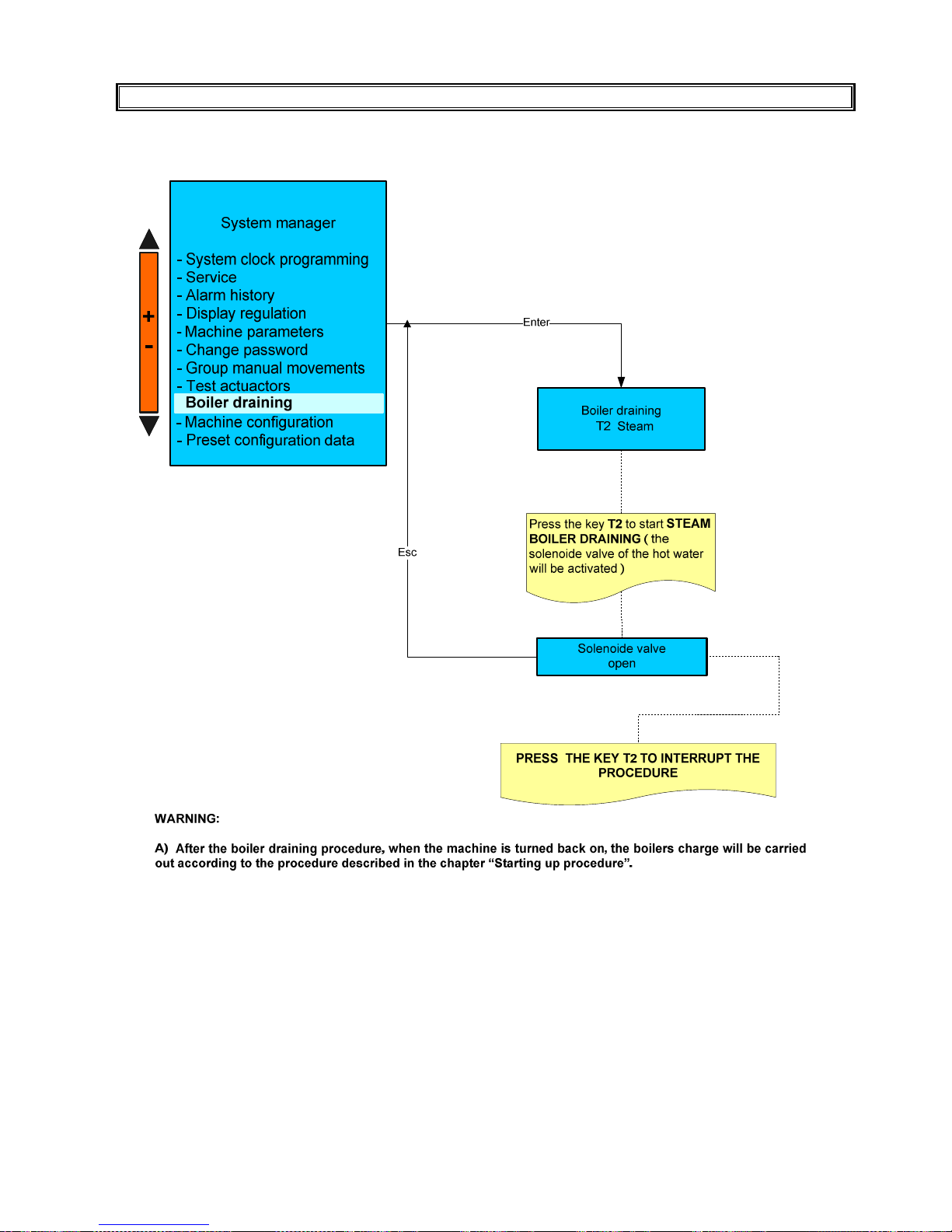
BOILER DRAINING
Page 42
LB.05080.00 Pag.42 16/04/2014
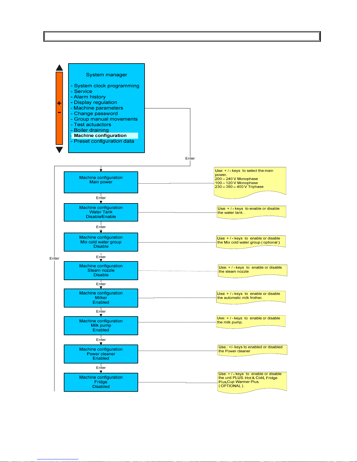
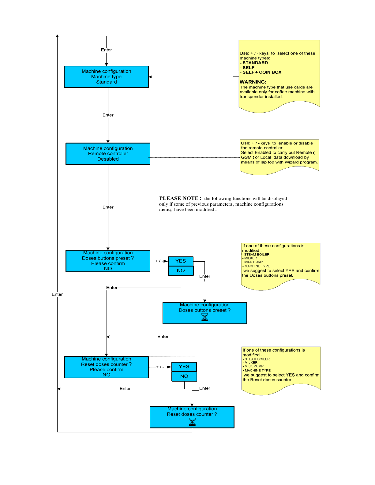
MACHINE CONFIGURATION
Page 43
LB.05080.00 Pag.43 16/04/2014
Page 44
LB.05080.00 Pag.44 16/04/2014
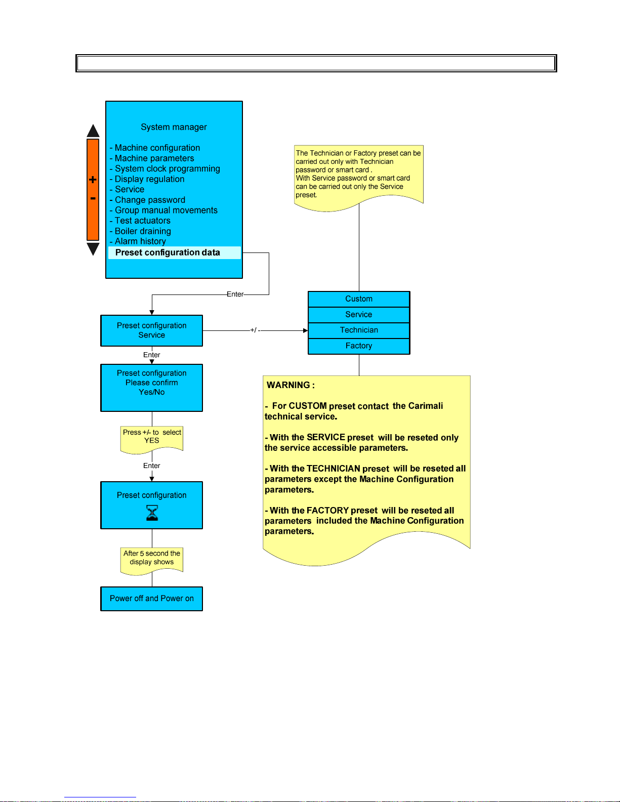
PRESET PARAMETERS
With this function, all the set up values, machine counters and passwords take the default values set up by the
manufacturer.
PLEASE NOTE:
By power OFF and power on, it is meant clearing and giving voltage to the machine.
Page 45
LB.05080.00 Pag.45 16/04/2014
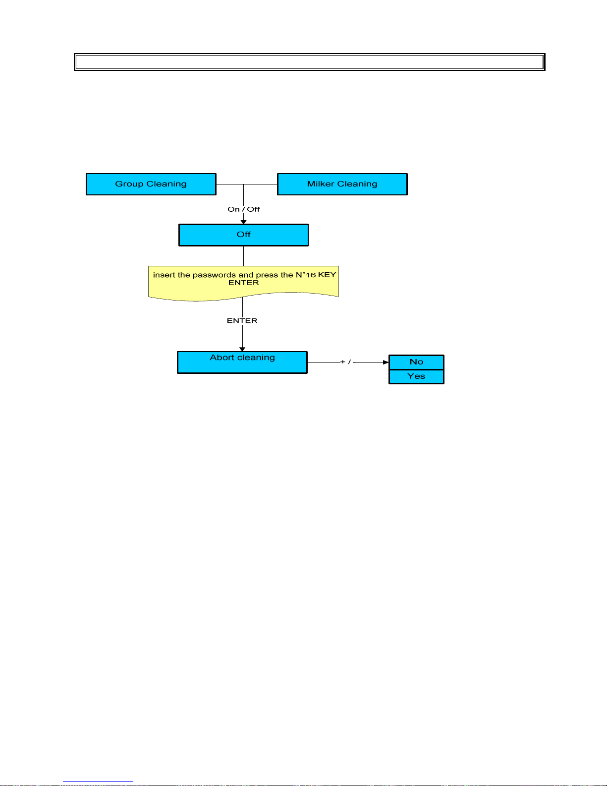
CLEANING PROCESS ABORT
If you want to interrupt the cleaning procedure for group or whisk or milk frother follow the procedure:
( ONLY WITH THE TECHNICIAN OR SERVICE PASSWORD )
Page 46

LB.05080.00 Pag.46 16/04/2014
TROUBLE SHOOTING
1) 10 Time out pulses, upper piston motor
10 No H. Motor puls
This alarm is visualised on display by code 10
Causes: the upper motor encoder has not received pulses for 3 seconds, since the motor is not running
Result: the machine is switched OFF.
Check the following:
1) Wrong or misconnect electric connections
2) Faulty gear motor electric
3) Faulty encoder card
4) Group movement card
5) Faulty master card
2) 11 Time out pulses, lower piston motor
11 No L. Motor puls
This alarm is visualised on display by code 11.
Causes: the lower motor encoder has not received pulses for 3 seconds, since the motor is not running.
Result: the machine is switched OFF.
Check the following:
1) Wrong or misconnect electric connections
2) Faulty gear motor electric
3) Faulty encoder card
4) Group movement card
5) Faulty master card
3) 12 Upper motor error alarm
12 H. Motor error
This alarm is visualised on display by code 12
Causes: a mechanical shutdown occurred to the gear motor or the upper piston encoder is not reading the impulses
correctly.
Result: the machine is switched OFF.
Check the following:
1) Gear motor defective
2) Gear motor not aligned with the brewing chamber
3) Faulty master card.
4) 13 Lower motor error alarm
13 L. Motor error
This alarm is visualised on display by code 13.
Causes: a mechanical shutdown occurred to the gear motor or the lower piston encoder is not reading the impulses correctly
Result: the machine is switched OFF.
Check the following:
1) Gear motor defective
2) Gear motor not aligned with the brewing chamber
3) Faulty master card.
Page 47

LB.05080.00 Pag.47 16/04/2014
4) 15 Alarm of too much coffee in the brewing chamber
15 Too much coffee
This alarm is visualised on display by code 15
Causes: the upper piston has positioned itself where the wet seal of the piston gasket in the brewing chamber is not
guaranteed.
Result: the machine is switched OFF.
Solution: carry out the following controls.
1) Reduce coffee quantity
2) Clean the upper piston gasket from any coffee residue
3) Check the upper piston alignment with the brewing chamber.
4) Faulty encoder
Please Note: before alarms 4) and 6) the upper piston tries to insert itself into the brewing chamber twice.
6) 32 Boiler filling alarm
32 Filling up T.O.
This alarm is visualised on display by code 32
Causes: the stage of boiler fillings has exceeded the maximum time of 2 minutes; the level of the probe (SLC) has not been
reached.
Result: the machine is OFF.
Check the following:
1) Level probe (SLC) is dirty, so isolated from the water (the complete filling of the boiler is checked)
2) no water from mains
3) low water pressure
4) faulty motor pump
5) faulty filling solenoid valve
6) incorrect electrical connections (level probe -SLC- misconnected wire).
7) PC board relè
7) 38 Steam boiler temperature alarm
38 Boiler temperat.
This alarm is visualised on display by code 38
First case: the temperature inside the steam boiler has reached the limit value of 129°C (264.2°F) or more.
Result: boiler heating is interrupted and all dose buttons are disabled.
Solution: turn OFF the machine. Replace the electromagnetic switch as its contacts might get stuck. Turn the machine ON.
Second case: the temperature probe is defective. The probe sends the following signal to the pcb: 0 Ohm.
Result: boiler heating is interrupted and all dose buttons are disabled.
Solution: turn OFF the machine. Replace the temperature probe. Turn the machine ON.
Third case: the temperature probe is defective. The probe sends the following signal to the pcb: 154 Ohm (short circuit).
Result: boiler heating is interrupted and all dose buttons are disabled.
Solution: turn OFF the machine. Replace the temperature probe. Turn the machine ON.
8) 34 Steam heat time–out alarm
34 Steam heat T.O.
This alarm is visualised on display by code 34
Cause: It indicates that the boiler heating up stage has exceeded the 15 minutes time-out.
Result: the machine is OFF.
Check the following:
1) Faulty electromagnetic switch
2) The boiler safety thermostat has set in (see alarm description of boiler safety thermostat)
3) Software problem (carry out machine preset)
4) Faulty Master board electromagnetic switch
5) Safety thermo switch.
Page 48

LB.05080.00 Pag.48 16/04/2014
9) 35 Check flow lines
35 Check Flow Lines
This alarm is visualised on display by code 35
Cause: It indicates that when the machine is in stand-by there is a leakage from the coffee hydraulic circuit.
Result: the machine is OFF.
Check the following:
1) leakage from the expansion valve
2) leakage from the coffee group solenoid valve.
3) leakage from the by pass solenoid valve. ( optional )
4) leakage from the mix cold water solenoid valve for group ( optional)
5) leakage from the no-return valve
6) leakage from the tubes of the coffee hydraulic circuit
10) 40 Flowmeter alarm
40 Flowmeter error
This alarm is visualised on display by code 40.
Cause: the flowmeter is not sending signals to the control unit within a time-out of 5 seconds.
Result: delivery continues up to a time-out of 120 seconds or until the selected key is pressed.
Check the following:
1) No water from mains (coffee is not dispensed)
2) clogged group piston filters (coffee is not dispensed)
3) faulty group solenoid valve (coffee is not dispensed)
4) clogged inlet filters (coffee is not dispensed)
5) blocked flowmeter (coffee is not dispensed)
6) faulty electrical connection (coffee dispensed continuously).
Note: If the coffee is dispensed continuously, use the machine as if it were manual: press the required key to start up the
dose, then press the same key to stop the dose being dispensed, after checking the amount in the cup.
If dispensing continues until the above mentioned time-out of 120 seconds, the dispensing will be stopped and display
shows:
41 Infusion T.O.
This alarm is visualised on display by code 41.
The message signals that a time-out problem of the flowmeter occurred.
At the next dose the message will be cancelled if dispensing is carried out correctly.
Check the following:
1) The dose programmed is too long. ( Program it again ).
2) The delivery is too slow : the grinding is too fine or the filter is clogged.
Page 49

LB.05080.00 Pag.49 16/04/2014
11) 60 Corrupted data alarm
60 Corrupted data alarm
This alarm is visualised on display by code 60
First case: This alarm is visualised during machine functioning
Cause: incorrect operating data in machine memory.
Result: machine shutdown.
Solution: carry out the following controls.
1) Verify programming data relevant to the operation that is being carried out. They might be varied and therefore the
machine does not recognise the new data.
2) Carry out “PARAMETERS PRESET” procedure (see chapter system programming configuration data preset).
Second case: software programming values or data incorrect, data inserted by means of P.C. programming incorrect.
Result: machine shutdown.
Solution:
1) Carry out “PRESET CONFIGURATION DATA” procedure
2) Insert new software by means of P.C.
12) 63 Clock error
63 Clock error
This alarm is visualised on display by code 63
Solution: check the following:
a) run down battery
b) faulty master board
13) 90 Water softener alarm
90 Change H2O filter
This alarm is visualised on display by code 90
Cause: the flowmeter has reached the maximum value of XXXXX litres of previously programmed water, which may be
dispensed.
Result: none.
Solution: renew the softener salts. To cancel the alarm, see the Info -Reset paragraph for further information.
Note: this alarm does not block dispensing. The softener alarm can be excluded by setting the litre value to zero (see
Service – Maintenance set-up paragraph).
Page 50

LB.05080.00 Pag.50 16/04/2014
14) 91 Group maintenance alarm
91 Group maintena
This alarm is visualised on display by code 91
Cause: the group has reached the number of programmed cycles (see Service chapter).
Result: none.
Solution: check the group and cancel the alarm following the procedure of the chapter info reset.
15) 92 Machine maintenance alarm
92 Maintenance
This alarm is visualised on display by code 92
Cause: the machine has reached the number of programmed cycles or the inspection date (see Service chapter).
Result: none.
Solution: check or/and replace the wear parts and cancel the alarm following the procedure of the chapter Info reset.
16) 93-Tools maintenance alarm
93 Grinder mainte.
This alarm is visualised on display by code 93
Cause: the tools have reached the set up working time (see Service chapter )
Result: none.
Solution: replace the tools and cancel the alarm following the procedure explained in the info reset chapter.
17) Safety valve operation.
No messages on the display
Cause: overpressure in steam boiler
Result: the safety valve opened at 1.7-1.9 bars, the steam is conveyed to the drip tray by means of a silicone tube.
Cause: overpressure in the steam boiler or faulty safety valve.
Solution: carry out the following controls.
1) Temperature probe of the boiler (see boiler temperature alarm)
2) Contacts of the electromagnetic switch of the electric element are stacked
3) Replace the safety valve in case it releases steam at a pressure lower than 1.7 bars,
18) Klicson cutoff
No messages on the display
Cause: The temperature of the boiler has reached the limit of 145°C.
Result: the heating is interrupted.
Solution: carry out the following controls.
1) Reset the klicson by means of pressing the red button on it (open the left hand side of the body - machine).
2) Contacts of the electromagnetic switch of the electric element may be stuck.
3) Faulty klicson
4) The water level in the boiler has dropped lower than the resistor
WARNING:
To activate the safety thermostat, it is necessary to press the button placed at the centre of the thermostat itself
Page 51
LB.05080.00 Pag.51 16/04/2014
SPECIAL FUNCTIONS FOR MACHINE CALIBRATION
1) Calibrating the coffee dispensing pressure (pump pressure).
To calibrate the coffee dispensing pressure (8-9 Bars), rotate the “MP” pumping body screw (see hydraulic diagram)
clockwise to increase it, and anti-clockwise to decrease it.
The adjusting screw is reached through the special hole behind the coffee grounds bin.
The coffee dispensing pressure is displayed on pressure gauge “7” (see hydraulic diagram) ; when the machine is in the
coffee dispensing phase
2) Calibrating the coffee grinding degree.
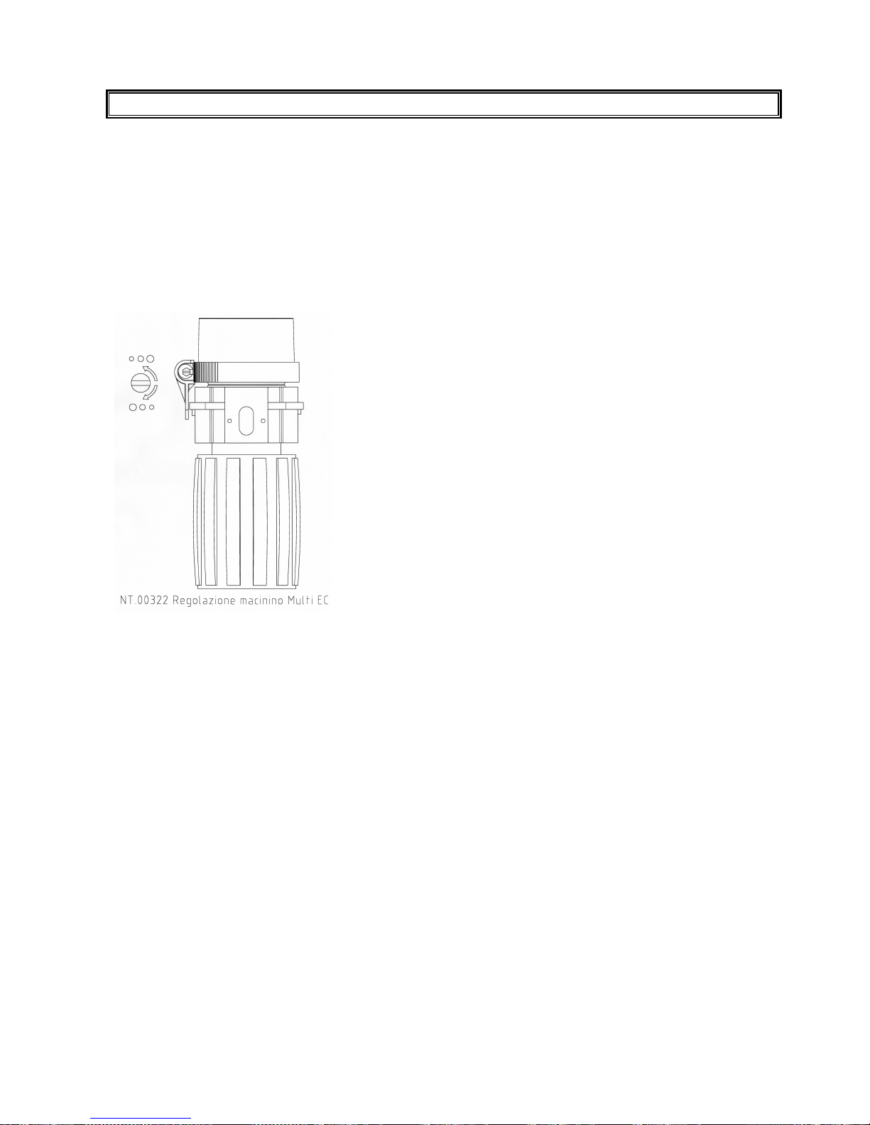
To calibrate the coffee grinding degree, rotate the grinder’s adjusting screw (see annex) clockwise to increase it, and anticlockwise to decrease it.
3) Calibrating the flow adjustment of the coffee outlet.
In order to calibrate the dispensing speed and change the amount of coffee cream, turn the screw of the coffee outlet
regulator on the upper piston (see hydraulic diagram) clockwise to decrease it and anti-clockwise to increase it
We recommend making the above adjustment while the coffee is being dispensed.
Page 52

LB.05080.00 Pag.52 16/04/2014
RECOMMENDATIONS FOR A CORRECT PREVENTIVE MAINTENANCE
The aim of this schedule is to prevent as far as possible equipment from breaking down, through the periodical check-up
and replacement of components subject to fair wear and tear, thus reducing service calls and relevant cost in working hours.
This schedule is based on the suppliers recommendations along with previous service history on equipment currently out in
the field.
It is designed to assist in extending the operational life of the equipment.
A. Pre delivery inspection:
We test all machines before shipping using water. Therefore we consider our machines ready to installation.
Anyway we suggest to carry out a Pre Delivery Inspection on all machines before deliver them to final customer. PDI can
detect inconveniences which may occur during transportation or a long storage. For instance:
- screws and nuts which fit the body-work may become loose;
- flowmeter may be block by dust especially after long storage;
- screws which fit the power supply wires may become loose.
B. 2 or 3 weeks after installation:
Parts to be checked or adjusted:
1. the grinder/s settings
2. the dose settings
3. if daily cleaning of group and milk frother is carried out by the operator.
C. At 4 months’ intervals:
Parts to be changed:
1. o-rings for milk frother
2. milk silicone tube for milk frother
3. o-rings for group pistons.
Parts to be cleaned or replaced (check and decide on site):
4. o-rings for the drip tray
5. group upper piston micro screen
6. group lower piston screen
7. milk frother
8. clean the hopper by the oil of the coffee
9. clean the coffee chute by means of a dry brush
Parts to be checked or adjusted:
10. grinder setting (coarseness of the coffee powder)
11. air adjustment for milk frother
12. coffee silicone tube
13. pump pressure should be 8-9 bars, check after had closed the coffee flow valve on upper piston
14. coffee boiler expansion valve should leak at 13 bars after a few coffee deliveries
15. front door switch
16. grounds beans tray switch
17. heating element of the brewing chamber (PTC), if it's not working check the fuse next to the group
18. check the gasket underneath the sweeper
Check the functioning of the machine with the customer:
19. dose settings (setting of milk frother, steam boiler pressure…)
20. that the double coffee spout delivers consistent quantity of coffee in the cup, if not replace it
21. check how many times the group cleaning procedure has been carried out
22. check how many times the milk frother cleaning procedure has been carried out.
Page 53

LB.05080.00 Pag.53 16/04/2014
D. Check at 12 months’ intervals
Same as points C1-22, plus replace the following:
1. steam boiler safety valve
2. coffee boiler expansion valve
3. grinder/s burrs (average 300-500 Kg)
4. if the group has delivered 75.000 cycles replace the motors
5. group upper piston micro screen
6. group lower piston screen
7. milk frother
8. milk frother air adjustment.
Suggestions:
Use the Test Actuators menu to check all loads of the machine: grinder/s, solenoid valves, contactor and heating element.
Check Alarm History menu, if you find any alarm check and solve the problem.
Test Actuators and Alarm History menu are part of the System Manager menu.
PLEASE NOTE: It is very important to verify that your customers carry out recommended daily cleaning procedures of
brewing unit and milk frother. More parts may be checked depending on your personal experience and also coffee/water
quality.
CONTROL UNIT LEGEND
A) MASTER BOARD
code no. 96.05148 (see electric diagram)
Please Note :
THE GROUP HEATING ELEMENT IS PROTECTED FROM ELECTRONIC FUSE ( PTC ).
B) MASTER BOARD LED LEGEND
LED-LD1: ( red colour) 12 V. DC power supply for triac and on/off relays
LED LD2 - Vcc : ( red colour) 5 V. DC power supply for microprocessor and electronic component
LED LD3 - VH: ( red colour) 24 V. DC main power supply for master board
Page 54
LB.05080.00 Pag.54 16/04/2014
The Carimali S.p.A. product you have purchased is subject to Directive 2002/96/EC of the European
Parliament and the Council of the European Union on waste electrical and electronic equipment
(WEEE) and, in jurisdictions adopting that Directive, is marked as being put on the market after
August 13, 2005, and should not be disposed of as unsorted municipal waste. For further information
please contact Carimali S.p.A..
The manufacturer reserves the right to change, without prior notice, the specifications of the
equipment illustrated in this publication; the manufacturer declines all responsibility for any
mistakes due to printing and/or typing errors contained in this publication.
All instructions, drawings, tables and information contained in this publication are reserved
and may not be reproduced entirely or in part or be communicated to a third party without
written authorisation from the manufacturer who holds exclusive rights.
Tabella Revisioni Data Note Revisionato da:
LB-05080.00 09/02/2014 Prima edizione Lorenzo Cauli
The manager
Maurizio Boffelli
Firma del Responsabile della Documentazione
 Loading...