

User manual
IM
DLP
3D printer
IM Series
s e R I E S

II
III
IV
V
Soft ware Install and Using
Preparing and Printing
Check Output
Maintenance
01
Carima-Slicer Install
02
Carima-Slicer Using
01
Printing Preparation
02
03
LCD Panel Using Method
Start Printing
01
Output Demount
02
After Output Processing
01
Printer Maintain
02
03
Other Maintain
FAQ
11
13
31
33
40
44
45
50
51
53
I
IM Series Introduction
01
IM Series Information
01
02
03
04
Component Name
Precaution
Whole Process
02
03
07
05
IM Series compatible material
08
C O N T E N T S
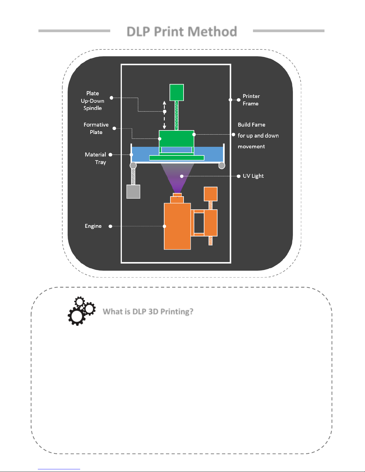
DLP Print Method
What is DLP 3D Printing?
DLP: Digital Light Processing Mask Projection Image Hardening Method
• A cross-section photograph of the output is laminated by irradiating the photo-curable liquid
resin with UV light..
• Due to the optical mask, the cross-sectional photograph of the output is totally inspected.
• Because of this surface unit lamination method, the output speed is fast and the surface
roughness high, so it is possible to make use of precision.
I IM Series Introduction
Hello.
This manual provides instructions on how to use the "IM Series".
Understand how to use "IM Series" through the manual and
experience "IM Series" easily and conveniently.
Check List
01 IM Series Information
02
03
04
Component
Precaution
Whole Process
05
IM Series compatible material

I IM Series Introduction
01. IM Series Information
IM Series is an ultra-precise DLP 3D printer, the most suitable printer to
implement a precise model, and is a 3D printer commonly used in the Design,
Jewelry, and Dental industries.
Model Name IM Series
Resolution 1980 X 1080
Light Source UV LED
Printing Size(mm)
96 × 54 × 150 110 × 85 × 200
130 × 74 × 100
Lamination
Thickness(mm)
0.025 / 0.05 / 0.075 / 0.1
Precision 50 μm
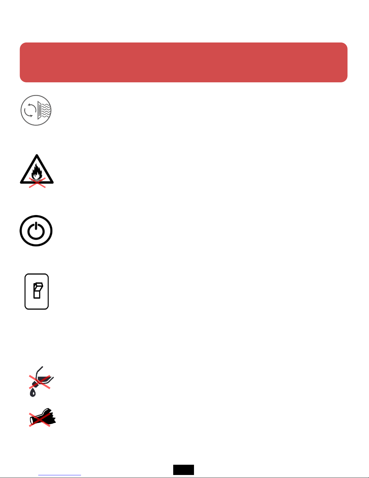
Product Size(mm) 304 x 315 x 622
Weight(kg) 22
Power 100-240V, 50/60Hz, 2.5A, 260W
Material DLP, SLA Resin
Control Type Control method using embedded touch screen
Using
Environment
18-26 (℃) / 20% - 50% (% humidity)
+
If you use the printer in this environment, it will help you to printing better.
1
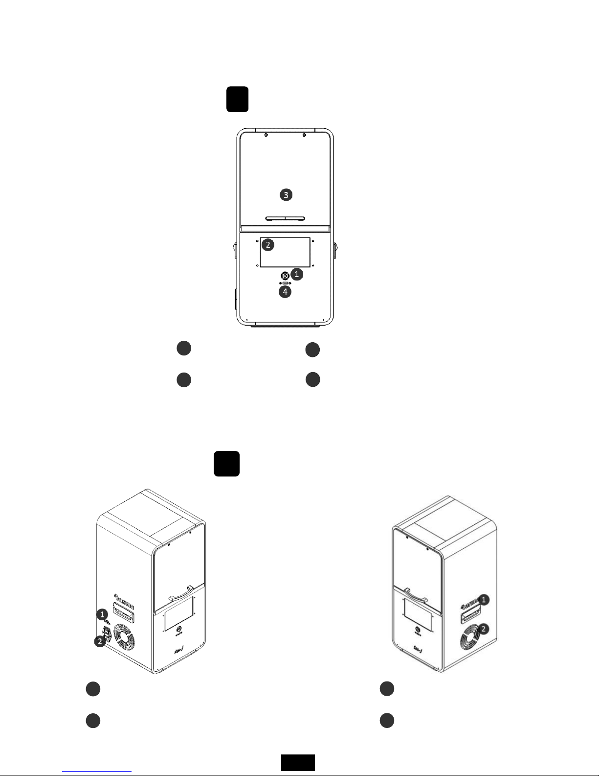
02. Component
A
Front
LED Power Button
LCD Touch Screen
Print Room Cover
USB Port
1
2
3
4
B
Equal Angles
Ethernet port
Power cable ports and switches
1
2
handle
Low Noise Cooling Fan
1
2
2
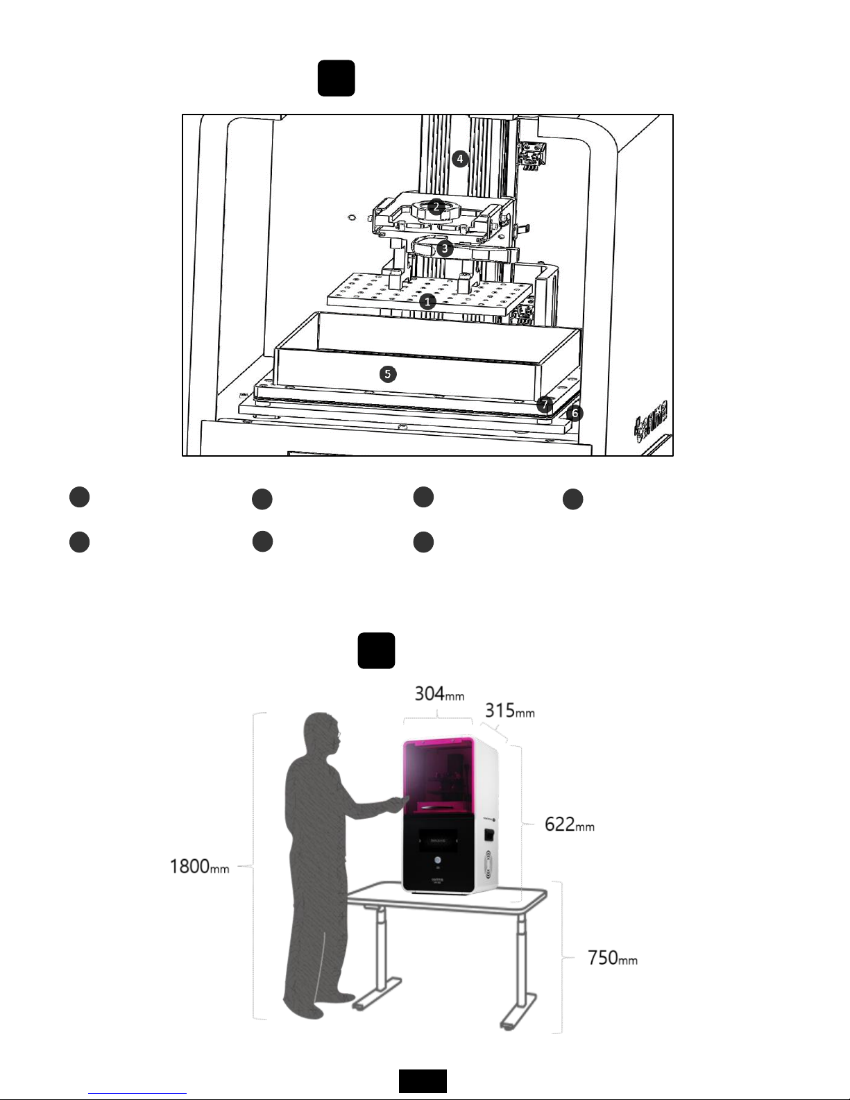
C
internal structure
Plastic plate
Open sheet tray
Plate fixing pin
Tray tilting axis
1
5
2
6
Plate handle
Tray fixing hex screw
plate vertical movement axis
3
7
4
D
Real Size
3
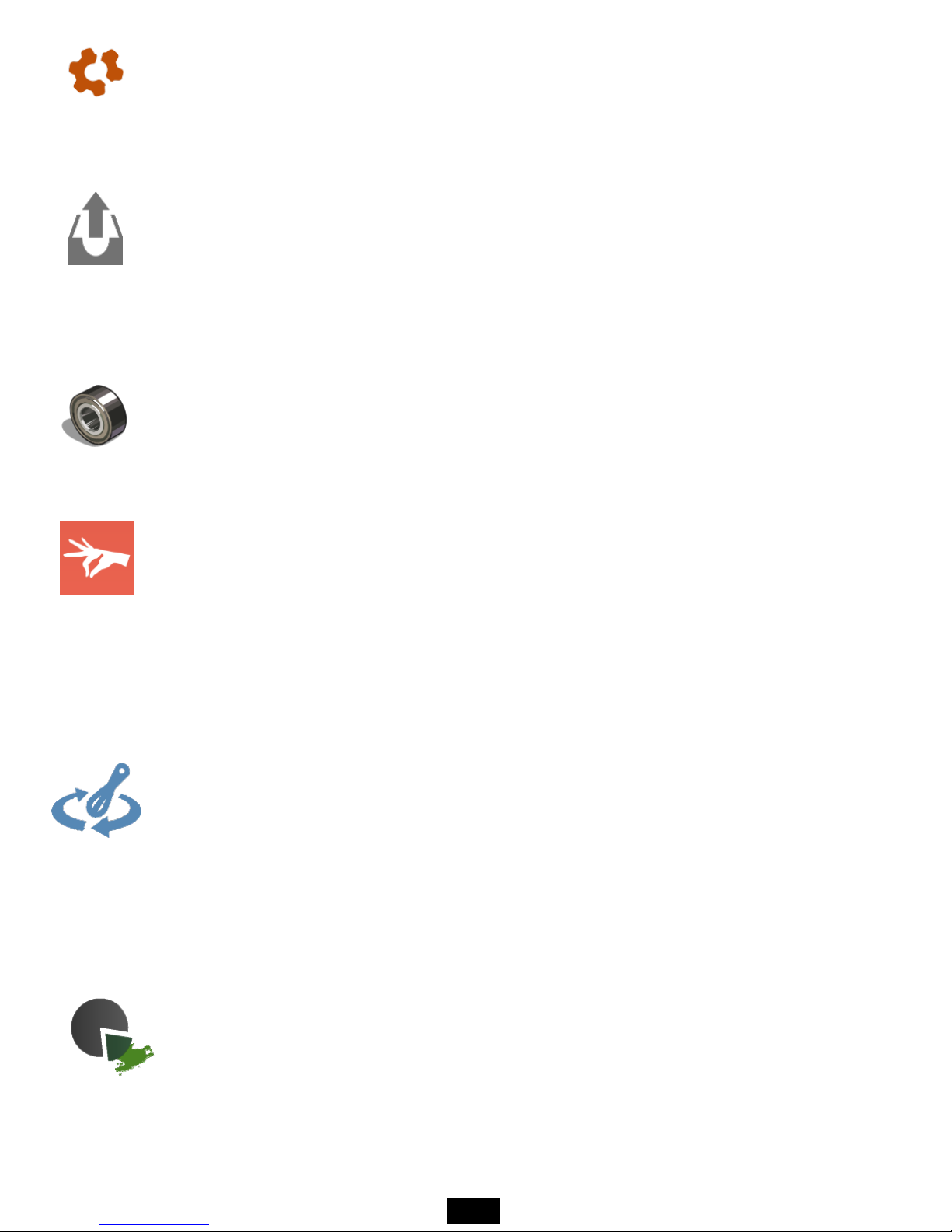
03. Precaution
This information is intended to protect your safety and property damage.
For your safety, please be aware of the precautions to prevent personal injury or printer damage.
When you print out the printer, it may cause the resin to smell distinctive, so
please install the printer in a well-ventilated place.
When using volatile objects near the printer, do not use it because there is a
risk of fire or explosion.
When moving the printer, be sure to completely shut down the printer, and
then remove the resin or tray to avoid overflowing the resin in the tray.
If the printer is on, do not off the power switch located on the back of the
printer. Forcible termination can shorten the life of the printer engine and
cause mechanical failure. Press the Exit button on the LCD panel to shut down
the printer.
If some objects such as water or other liquids, metal chips, or other conductive
materials are introduced into the printer, it may adversely affect the printer,
such as mechanical malfunction. In addition, do not operate with wet hands
because of the risk of electric shock, please wear the nitrile gloves and using.
4
If you touch the door or touch screen strained with gloves or tools, it may
cause malfunction(Touch screen malfunction, door crack, etc.).
If the tray removed while the plate attached after printing, impurities may fall
inside and cause a failure. First, remove the plastic plate, remove the tray
afterwards.
When removing the tray, be careful that the bearings that were used as the
bearing may be lost (If you lose, you may incur costs).
After the output, take out the resin remaining in the tray with a syringe, filtering
residue with a sieve, and store it separately.
If you put the resin in the tray due to frequent work, keep it closed that is not
exposed to the external environment as much as possible.
If the dyestuff of the resin stored in the tray is separated, it must be mixed with
a rubber spatula before printing.(If the sheet is damaged by storing the resin in
the tray for a long period of time, this is the customer's fault.)
After the output is completed, When you remove the plastic plate with the
printout, be sure to move the tray (tray) that supports the resin that falls down
so that the material does not fall inside the product. If the material falls inside
the product, it may cause deformation or breakdown.
5
If the printer power cable and USB cable are damaged due to being pulled or
stepped on the rough surface, please note that sparking or voltage
malfunction may occur. Also, if there is a lot of current in the power cord or
outlet, there is a risk of fire due to overheating.
The printer has potential risks in terms of chemical composition and voltage.
To prevent injuries to children and pets, install a printer in a safe place to
prevent accidents.
If the printer is installed in a location where there is a lot of humidity or
temperature changes, it may cause deformation or malfunction of the product.
If you disassembling or remodeling the printer artificially, the warranty benefits
will be lost and you will not be held liable for any loss caused by this.
For inquiries regarding A/S inquiries and product warranty, please contact
Carima Co., Ltd. for a friendly consultation.(82-2-3663-8877).
Malfunction or trouble due to non-compliance, tuning, disassembly, etc. are
recognized as customer errors and will be charged during the warranty period.
6
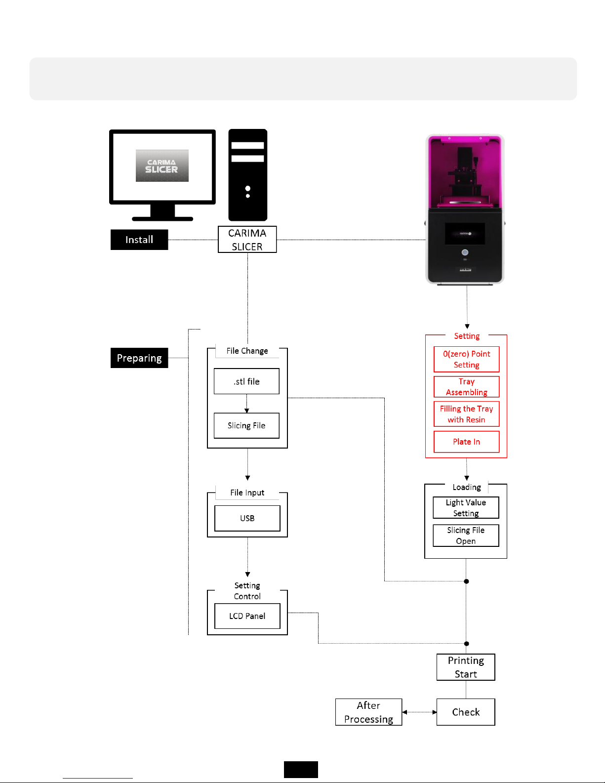
04. Whole Process
In order to output to IM Series, you have to go through the following
procedure.
7
IM Series
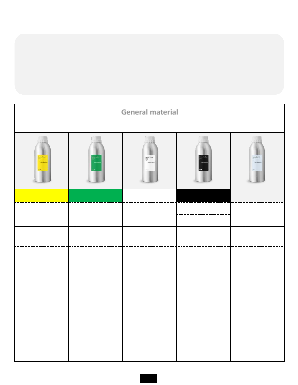
General material
Plastic-based material
Carima ABS-like Carima ACRYL Carima WHITE Carima Fast BLK Carima CLEAR
ABS-3DK83Y ACRYL-3DK83G WHITE-CRM011
Fast BLK-3DKBLK
CLEAR-CRM
CAM008
Prototype
Mock-up
Prototype
Mock-up
Prototype
Mock-up
Prototype
Mock-up
Prototype
Mock-up
Yellow-based
prototypes or
materials that
can be used for
3D modeling in
general.
For green-based
prototypes or for
the production of
full-scale models,
it is generally
possible to use
3D printing with
ABS.
It is a material
that can perform
3D printing work
for white base
prototype or real
size model
production.
It is a black
plastic type
general material
that Carima
developed in-
house, and it is
possible to
realize high
reactivity and
precision.
Transparent
prototypes,
transparent
materials that
can be modeled
on a full scale.
05. IM Series compatible material
The IM Series can be used for 3D printing using materials of various
characteristics. Among Carima's general material range, IM Series can output
all common materials. (However, I am not sure whether it will be possible to
output special materials other than Carima special materials.)
8
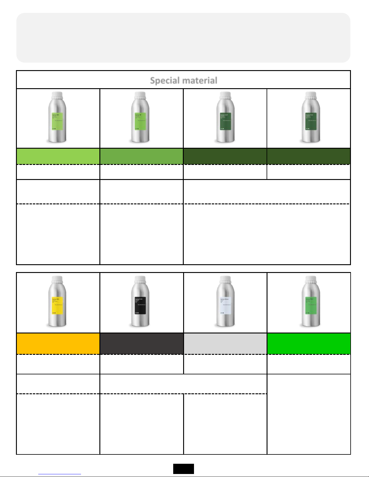
Carima HRN
Carima FLEX Carima Silicon Carima TRAY
HRN-3DKHR1
FLX-CFM005 Silicon-3DKSL1 TRAY-CDV300, CDP011
Heat-resistant material
Flexible material
Dental bracket
dedicated material
Heat-
resistant material
can withstand up to
200 degrees,
yellow base.
Special material with
soft rubber like
features.
Silicon material
Special material
Carima GRN Carima HR Carima CAST Carima WAX
GRN-CRM003 HR-CAM003 CAST-CAM002 WAX-CAM004
Flexible and strength-
based materials
Precision-only material
Precision jewelery output
and casting exclusive material
A material with some
flexibility and strength.
A material capable of
achieving a precision
of about 25 μm to 50
μm.
Rings that require precision, such as necklaces
and accessories The material can be used
professionally from the output of the model.
Among the special materials of Carima, IM Series can output all special
materials(However, I am not sure whether it will be possible to output special
materials other than Carima special materials.)
9
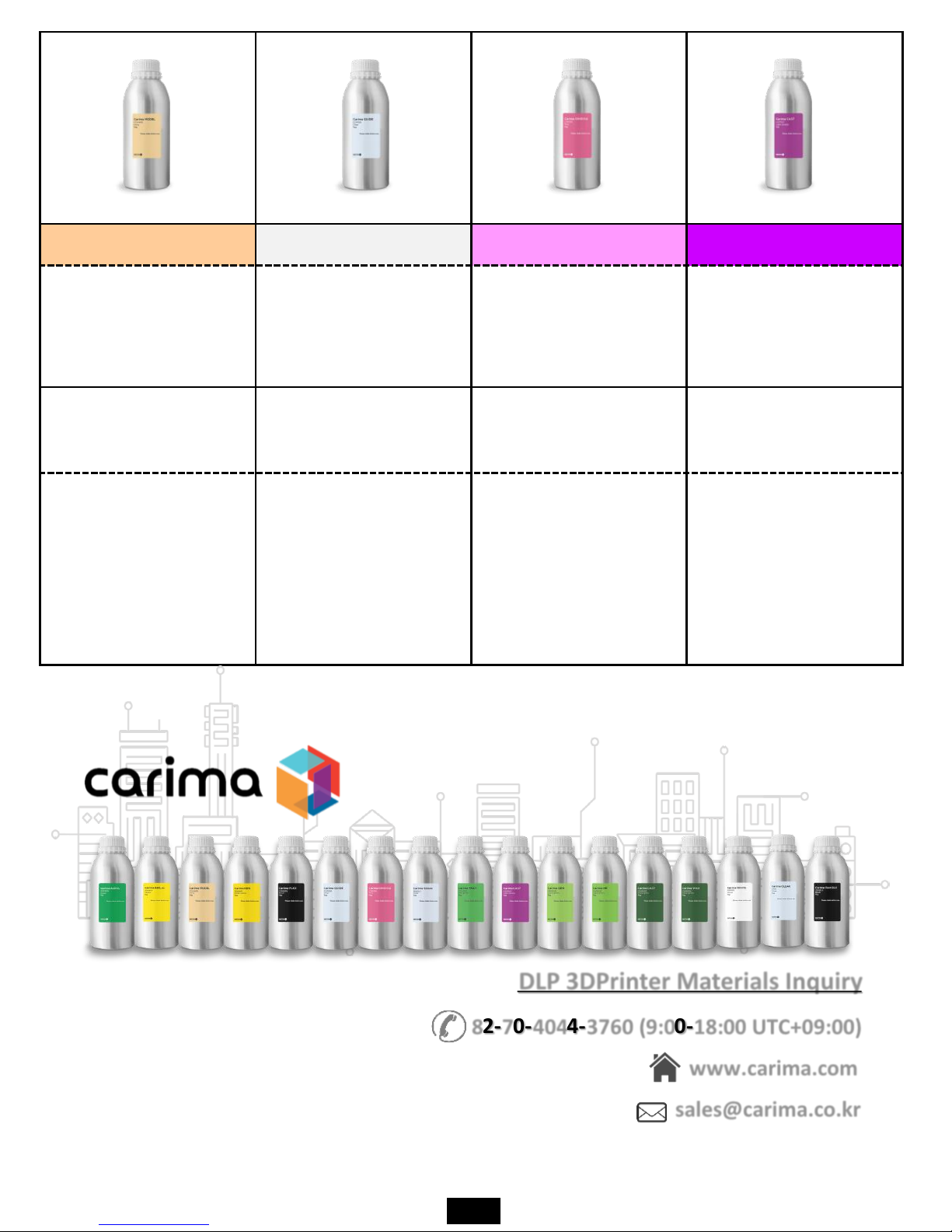
Carima MODEL Carima GUIDE Carima GINGIVA Carima CAST
MODEL-CDV400,
CDP013
GUIDE-CDP010,
CDP001,
CDV600
GINGIVA-CDP015
CAST-CDP012,
CDV100
Dental guide material
Implant guide material Gingiva material
Dental casting only
material
Based on flesh-based
high-precision output
of the dental upper
and lower mandible
Material.
Transparent-based
implant guide only
material.
A material similar to
the gums that can be
used to identify the
shape of the gums that
have subtracted teeth.
A special material that
can open teeth with
gold, silver, etc.
DLP 3DPrinter Materials Inquiry
www.carima.com
sales@carima.co.kr
82-70-4044-3760 (9:00-18:00 UTC+09:00)
10
II Software Install and Using
If you are using the IM Series, you must install
the slicer program provided by Carima.
Realize your imagination and experience
creation with Carima Slicer.
Check List
01
Carima Slicer Install
02
Carima Slicer Using
II Software Install and Using
01. Carima Slicer Install
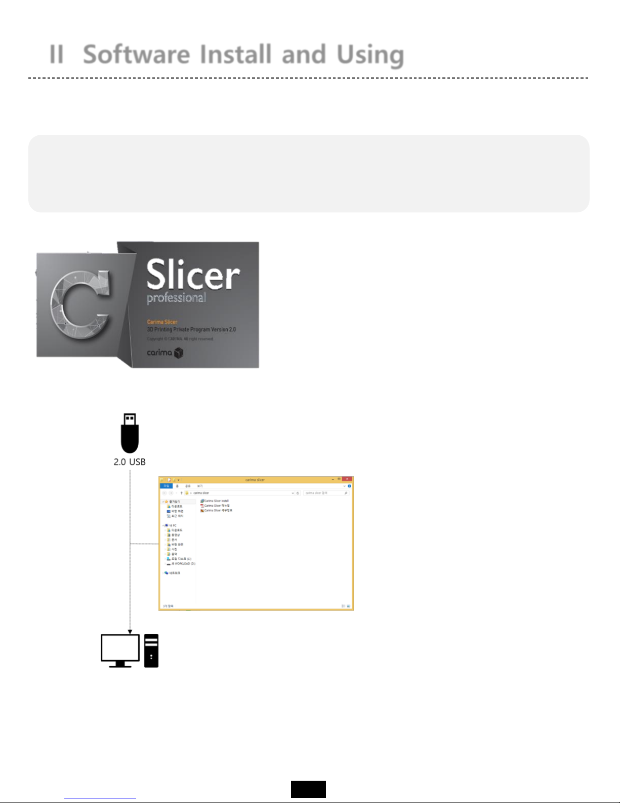
The Carima Slicer is a program that helps you to output from the IM Series.
Carima Slicer is a self-made slicing program
from Carima Co., Ltd. It is a program that
slices each model to output and makes it
into a picture form. It is easy to save it as
file such as stl, jpg, crv.
The Carima Slicer Setup program is attached to the USB
provided by Carima. Install CarimaSLICER with USB.
CarimaSLICER can not be installed on any other PC (or
notebook) other than one PC (or notebook).
★ CarimaSLICER is compatible only with 3D printers manufactured by Carima Co., Ltd.
You can not use CarimaSLICER with other 3D printers.
11
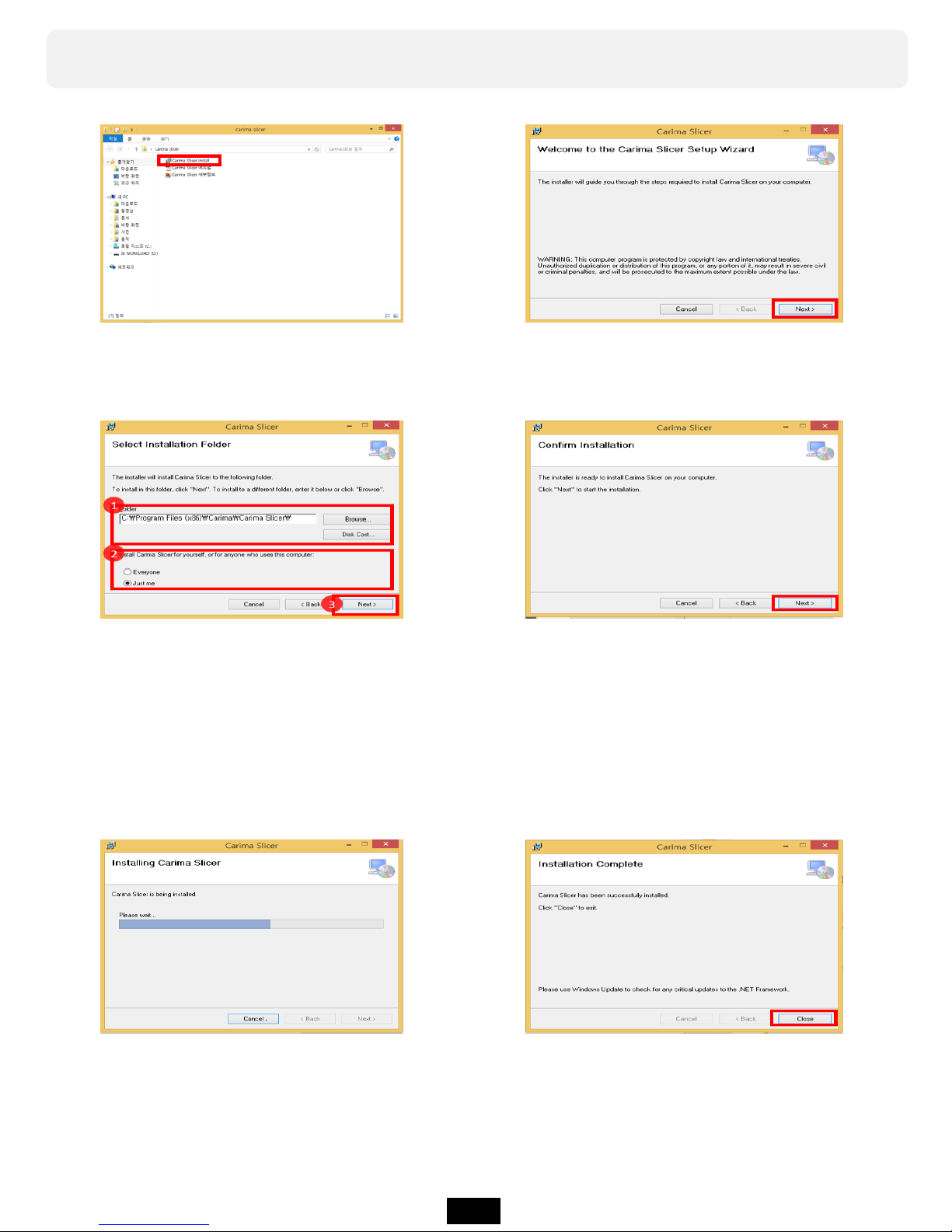
You can install Carima Slicer in the following process.
a. Double-click the Carima-
Slicer Install file.
b. Carima-Slicer Install Setup file
screen. Click Next>.
c. After specifying the path where
Carima-Slicer will be installed,
select one of "Just me" or
"Everyone" of the Windows
account and click Next>.
d. After completing the setup,
please proceed to the final
installation with the message
that installation is completed.
Click Next>.
e. Click Next> to proceed
with the installation.
f. When the installation
is finished, click Close.
12
02. Carima Slicer Using
You can apply a variety of settings to ensure easy use of the Carima slicer.
★ If CarimaSLICER is not installed properly, please contact
the following address. Carima 82 - 2 - 3663 - 8877
After registering, if you run Carima Slicer program,
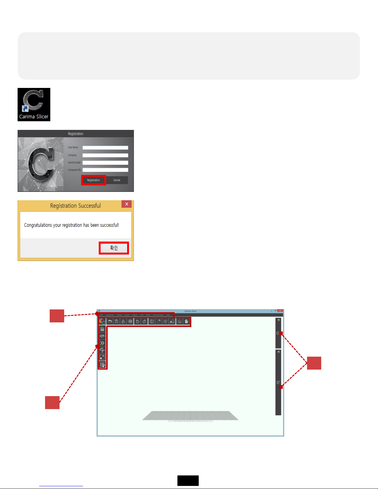
you can see the following interface screen.
C
A
B
Once you have completed the installation, the Carima slicer icon will be created on
your desktop. Double click the icon and start Carima slicer.
When you run Carima Slicer program, you can see the
following registration screen.
On the registration screen, only information about serial
number and computer information is displayed.
Serial Number and Computer Information are automatically
formed, so if you click Registration immediately, you will
get a message that the registration is as follows. Click OK
and meet Carima Slicer!
13
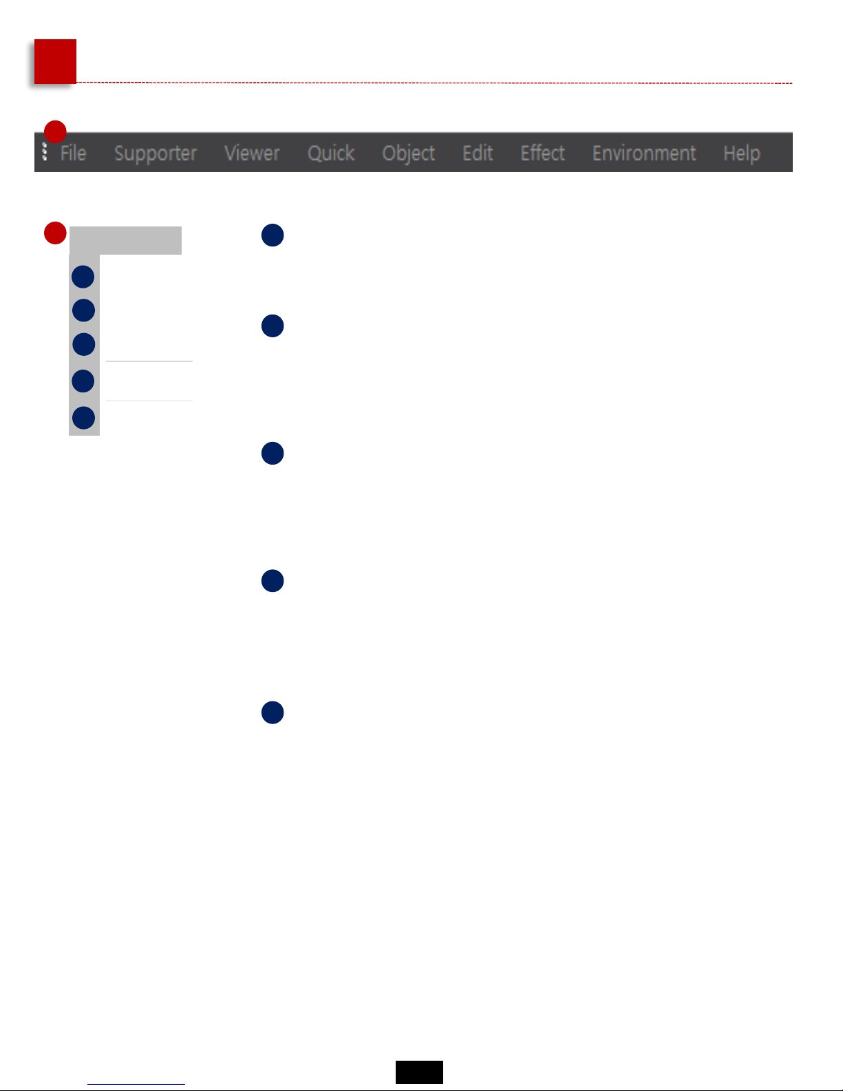
A
Carima-SLICER Basic Manu
1
File
Open
Save
Slicing
Config
Exit
a
b
c
d
e
a
Open
Stored files such as "stl" can be loaded.
b
Save
You can save models that you have worked with a
Carima slicer in slt, crv, and other file formats.
c
Slicing
The imported modeling files can be sliced into single-sided
photo files. The file is in JPGE format.
d
Config
You can change the color of the modeling file, set the user
name, build size, resolution, and image pixels.
e
Exit
Exit the Carima slicer.
1
14

2
a
Manual formation of type 1 supporters
Type 1 supporter manually formed from
printout and bottom
b
Manual formation of type 2 supporters
Type 2 supporter(Blue) that is manually
formed between printout and output
c
Base supporter
Outputs and supporters serve as support from
bottom
c
Type 1 supporter automatic formation
Automatically form type 1 supporter that
serves as a support from the printout and
from the bottom
e
Type 2 supporter automatic formation
Automatically form type 2 supporter that
serves as a support from the printout and from
the bottom
f
Automatic formation of all supporters
All supporters automatically formed
g
Delete all type 1 supporters
Delete all formed Type 1 supporters
h
Delete all type 2 supporters
Delete all formed Type 2 supporters
i
Delete all supporters
Remove all formed supporters
j
Supporter Settings
Change setting value such as supporter size
and length
Type 1. supporter
(Yellow)
Type 2. supporter
(Blue)
15

3
Viewer
Front
Top
Left
Right
Bottom
a
b
c
d
e
3
a
Front view
The loaded model can be seen from the front.
b
The imported model can be seen from above.
Top view
c
Left view
You can see the loaded model on the left.
d
You can see the loaded model on the right.
Right view
e
The imported model can be seen below.
Bottom View
Quick
Reflection in the X axis
d
e
Reflection in the Y axis
Reflection in the Z axis
a
b
c
a
Invert to X axis
Reversing the direction of the
model along the X axis
Move to the Center of X-Y Plane
Move to the Bottom of Z axis
b
Inverse to Y axis
Reverse direction of model in Y axis
c
Invert to Z axis
Reversing the direction of the
model along the Z axis
d
Centered on X-Y axis
Centered on X-Y axis
e
Z axis positioning
Zero position from the current
position to the bottom of the Z-axis
(molded plate)
4
4
16

5
Object
Move Object
d
Rotate Object
Scale Object
a
b
c
Arrange
Copy Object
Delete Object
e
f
Reset Crima Platform
g
a
Move model
You can move the model.
b
Model rotation
You can rotate the model.
c
Model Size
You can change the size of the model.
d
Origin placement
You can place the moved or rotated model
back to the origin.
e
Copy
You can copy the model the same way.
f
Delete
You can delete the model.
g
Initial Screen
The first time the Carima slicer returns to its
initial state.
5
Edit
Undo
Redo
a
b
c
Clear Undo Buffer
a
Back to Previous Work
You can return to the previous operation.
b
Go back to work
You can go back to work later.
c
Initialize workload
You can initialize the imputed computer
memory because of the large amount of
nested workloads.
6
6
17

Effect
Alpha Blending
d
Marking Slope Area
Boxing Selected Object
a
b
c
Outline Selected Object
a
Translucent effect
The model has a translucent effect.
b
The part where supporters will be formed is
displayed.
Show supporter formation part
c
Model Box Formation
A corner angle appears as the size of the
model.
d
Displays the outline of the model.
Model contouring
7
7
8
Environment
Expand Displayed Toolboxes
d
Rearrange Displayed Toolboxes
Show Build Platform
a
b
c
Show Notice Boundaries
8
a
View all action tools
All work tools appear to be visible.
b
Rearrange the wrong work tools.
Rearrange all working tools
c
Build view
Builds can be viewed in clear boxes.
d
You can hide or show the front panel.
Show and hide frontal display
Help
User Manual
About
a
b
a
Download the Manual
You can download the Carima slicer manual in
PDF format.
b
You can check the current slicer program
information.
About the Carima Slicer Program
9
9
18

Slicing Process
The initial start point of Start Slice # is set to 1.
If slicing is in progress, error, or pause, the slicing must be resumed and the starting point
can be set using Start Slice #.
a
Precision setting
Precision can be set in micron (㎛) units. The lower
the number, the greater the number of slices.
b
Anti-aliasing effect
You can reduce the appearance of the staircase type
shown in the sliced picture.
c
File name
You can set the file name to be sliced.
d
Set file storage location
You can set the location of the file to be saved.
The files are stored in crv, jpg format files.
e
Getting started with slicing
Slicing begins.
f
Show slicing progress
You can check the slicing progress.
19

A
B
C
D
A
B
C
D
Identify the entire slicing file
Check the front of the printout
Checking the image of a section slice
of the output
Supporter of printout
With the mouse wheel up and down, you can see all the cross-
sectional layers of the sliced output one after another.
a partial cross section
20

B
Carima-SLICER Toolbox
Open file
You can import modeling files
such as stl.
The imported modeling files can be
sliced into single-sided photo files. The
file is in JPGE format.
Save the file
You can save models that you have
worked with a Carima slicer in slt,
crv, and other file formats.
sliced
Detailed
settings
You can change the color of the
modeling file, set the user name, build
size, resolution, and image pixels.
undo
Redo
Bounding
Show
supporters
Translucent
effect
Rearrangement
Build
platform
Border mark
During modeling, if the model is outside
the build platform scope, a boundary
mark appears.
The build platform is formed in the form
of a box, so you can see clear build rules.
Reverts to the previous operation.
Go back to the next operation.
A corner angle appears as the
size of the model.
The part where the base
is formed is displayed
(red part).
The model has a translucent effect.
You can place the moved or rotated
model back to the origin.
21

Supporter Tool
There are all the options associated with the support that you set
up to secure your output.
Type 1 supporters can be
created (manual).
The model displays the part
where the supporter runs.
A supporter is created in the red area (the
supporter will be created even if it is not
red).
Display
Before
After
display
Type 1 supporters can be
created (automatic).
22

You can create a type 2
supporter (manual).
Type 2 supporters can be
created (automatic).
The Type 2 supporter is a supporter that connects between the two to make the most of the
fine or precise part of the model.
You can remove the type 1
supporter that you created.
You can remove the type 2
supporter you created.
You can remove all generated
supporters.
Type 1 and Type 2 supporters
can be created automatically
(random settings).
You can add a base supporter
to the output (yellow base).
You can set supporter length,
size, thickness and so on.
23

View Manu
You can set the output to be viewed in various ways.
Front view
Top view
Bottom View
Right view
Left view
24

Quick Manu
This menu allows you to change the output direction to various
directions.
Switching up and down
Tilting left and right
Forward and backward
switching
Bottom (Zero) All axis
coordinate alignment
Bottom (Zero) Z-axis (Up and Down) Coordinate alignment
25

Move Manu
• Move to Z-axis
(up and down)
• Move to X axis
(left and right)
Top View
• Move to Y axis
(front and back)
Top View
You can freely move the printout left, right, front and back, up
and down.
26

Rotate Manu
The output can be freely rotated at various angles.
ex) Rotate 90 degrees
Top View
• X-axis rotation
• Y-axis rotation
• Z-axis rotation
27

Scale Manu
Output can be adjusted to various sizes.
• Resize X axis: You can narrow or widen to the left or right.
• Resize Y axis: You can narrow or widen in the forward and backward direction.
• Adjust Z scale: Narrow or widen up or down
• Full size adjustment: can be narrowed or widened in all directions
28

Etc. Tool
Ancillary work tools include border marks, build marks, forward alignment, and
translucent effects.
Ability to view printout
Translucent effect
Ability to display the entire build
Show Build
The boundary of the part that is
displayed in red when the output
size is changed or the build is
exceeded due to movement
Border mark
Function to rearrange forward again
Forward Sort
Open and close all work tools
Open & Close Work Tool
29

You can check the information about the printout, application tools such as
supporters, etc.
C
Object Information
30

III Preparing & Printing
Before printing, you must preparing the IM
Series state that can output.
Now we will explain the procedure from the
first opening to the output of the IM Series.
Check List
01
Printing Preparation
02 LCD Panel Using Method
03
Start Printing

III Preparing & Printing
01. Printing Preparation
To start output to the IM Series, you must first set the material. For material
setting, there are tray preparation, resin swelling, plate.
2
3
Fixing the plate and place with the fixing pin.
Prepare the printing by pouring resin into the tray.
1
Fit the separated formative plate into the formative top.
If you scratch the sheet of ⑤ with a sharp blade or cutter knife, be careful not only to tear it
but also to contaminate the engine room with resin.
31

All you really need to know
Information on the use of resin
When using a resin, please use all means wearing nitrile gloves. When
replenishing resin, please charge it before possible output. Inevitably, when
replenishing the resin during printing, press the "Pause" button and slowly
insert the resin after the operation is completely stopped. Charging the resin
during printing can cause bubbles and adversely affect the printout.
Information about using the tray
As you print, the surface of the sheet is punctured, torn, and
loosened. In this case, since the resin seeps out and can not be
used, replace it with a new tray.
If the user accidentally prints or hardened debris hurt the
surface of the sheet, these symptoms will appear in a short time.
Information on formative plate maintain
Information about using the tray
You can clean the modeling plate by scratching the
molding plate with wax or wiping it with a wet tissue. If
you want to use another resin for output, please wipe the
resin before you clean it.
The life span of the optical engine lamp is 20,000 hours, and the
lamp brightness may be lowered when used over the life span.
If the lamp usage time exceeds 20,000 hours, you can improve
the output quality by replacing the lamp.
32

LCD Panel Tree
02. LCD Panel Using Method
On the LCD panel, you can make most of the settings required for printing.
Initial Screen
main
screen
Right
and
Left
move
Output
data
Right
Preferences
Left
Formation parameter
setting
Set the plate height
Printer settings
Printer information
Output related
settings
Data-related
settings
Screen
Touch
Move between dataHelpPreparing service
Administrator
mode
This menu is used by Carima
technician for visiting A / S.
Access is in Carima
>
>
Basic Menu
Inaccessible menu
Preparing menu
Shut
down
33

LCD Panel Usage
HOME
A. Initial Screen
When the printer is turned on, the loading screen appears.
Make your ideas come true with Carima's 3D printer!
B. Main Home Screen
a b
a
b
Preferences
Output and data-related settings
34

LCD Panel Usage
• Formation parameter setting
Environment Set
1
2
3
4
The shape parameter setting menu allows you to fine-tune
the light of the engine being examined for output.
1
2
3
4
a
The basic exposure time means the time to shoot the output image from the optical engine at the time of molding
The initial exposure time means the exposure time for attaching the output to the molding plate during molding
The initial exposure layer means the number of layers to which the initial exposure time is to be applied
The divided exposure time means the time for dividing the exposure time
35

LCD Panel Usage
Environment Set
a
• Set the plate height
1
2
3
1
2
3
The height of the plate can be set to the amount of
movement of the plate after printing,
after printing, or during normal operation.
During molding, the movement amount of the plastic plate can be set during the printing.
After molding, the amount of movement of the molding plate can be set after the output.
The movement amount of the plate can be set when the tray separation, the cleaning of
the molding surface, and generally the movement of the plastic plate are required.
36

LCD Panel Usage
Environment Set
a
• Printer settings
1
2
3
The printer settings are for use with LCD Embedded.
You can set the language settings, embedded update settings,
cleaning the plastic surface(sheet) of the tray, and so on.
1
2
3
Language setting: You can set the language such as Korean, English, Japanese.
(See p.36 Additional Information)
Update: There is a way to update via Embedded update via USB and to update (online
update) by accessing Carima's update server.
Currently "Online Update" is in preparation for service (see p.36 Additional Information)
Cleaning the mold surface: When the mold surface is cleaned by the menu that is
used when there is residue or residue on the sheet due to the output failure, OFF
turns on and UV light is irradiated for 2 ~ 3 seconds.
After the light is illuminated, the menu changes to OFF again.
(See p.36 Additional Information)
37

LCD Panel Usage
Environment Set
a
• Printer information
1
2
3
The printer information includes the model name, build size,
resolution, storage space, IP address, and software version for
the printer you are using.
1
2
3
You can check information such as product name, build size, resolution, storage
space, IP address, and software version.
Tip: You can find information that will help you with your output.
We are currently in the process of preparing the service.
Administrator mode: Administrator mode is used by Carima technician during business
trip A / S. Customers can not use it, but if you have any questions, please contact
Carima Customer Service (82-2-3283-8877).
38

LCD Panel Usage
Environment Set
a
• Printer shutdown
Press the Exit button to exit the printer.
Additional Information
• This message will appear when cleaning
the molding surface.
• 프린터 설정에서 USB업데이트를 진행하면
이와 같은 메세지가 나타납니다.
• Pressing the save button at the bottom
right of the molding surface height setting
will display a message like this.
• If you do not have an update file when you
perform USB update from the printer settings,
this message will appear.
• LCD임베디드 언어를 설정하면 이와 같은
메세지가 나타납니다.
• The above picture shows the administrator
mode screen.
• This menu is not available to customers.
39

Start Printing
Output and data-related settings
b
• Data List
When you press the directional key located in the middle right of the main menu,
the data list of this output appears.
If the data is not modeled when you click on
the data, this message appears.
If you press the data again in the right data list,
the data saving icon and data delete icon will appear.
1 2
1 2
1
2
Data storage message
Data delete message
03. Start Printing
On the LCD panel, you can make all the settings required to output to the
DM250.
40

Start Printing
Output and data-related settings
b
• Printing
If you click the data you want to print on the right data list,
brief information of the printout appears on the left.
When you press the circle here, the output starts.
The data to be output is read.
Just before the printout, a message will be
displayed to remind you that the sculpture
is attached to the molding plate.
Printing starts.
41

Start Printing
Output and data-related settings
b
• During printing, setting
If you press the circle "Print" during printing, the setting menu will appear as shown on the right.
1
2
3
4
1
Pause
2
Preview
3
Auto shutdown
4
Stop and terminate printing
• Pause the print job in progress.
• Press again to start printing.
• You can stop the print job and preview
the progressed output.
• The print job is completed and the
printer is automatically shut down.
• Stop the print job in progress and
terminate the output.
42

Start Printing
Output and data-related settings
b
After canceling the output, Main Screen: From this screen,
Data can be loaded and output.
• In the Output Shortcut Menu, you will be taken directly to the screen of the corresponding
output so that you can print out the previous output.
• If you want to print another output, press the blank screen (red part) in addition to the circle
menu to move to other data.
43

IV Check Output
When printing is finished, the printout must be
removed from the printer.
Be sure to read the information to remove the
printouts and improve the output quality.
Check List
01
Output Demount
02
After Processing Output

01. Output Demount
When the output is complete, you should remove the printout from the
mastering plate. Wear nitrile gloves and remove the printouts.
When the output is completed, the
formative plate with the output is
automatically raised.
In this state, turn the fixing pin to
remove the formative plate.
Put the formative plate upside down to
remove the printout. Detach the output and
using a cutter such as a knife or scraper.
※ Caution
Please be careful when using cutter
knife or hera.
44

02. After Output Processing
If the printout is removed from the formative plate, manual work such as
cleaning, supporter removal, and curing is required. You should still wear
nitrile gloves.
45

1
Removing supporters
The supporter can be output with the supporter 1 or 2 type according to the method set in
the slicing program before output, and both supporter 1 and 2 type can be set and output.
When the output is complete, remove the supporter by hand from the printout removed
from the plate.
After curing without removing the supporter, you can remove it using the nipper on the
base component when removing the supporter.
If the supporter remains on the cut of the supporter in the printout, you can use a
sandpaper to polish the surface by polishing.
Density Usage
Purchase
recommended
Sandpaper Type
60-120
For removing rough and rough surfaces (Metal, high-strength plastic such as
FRP, cement)
Cloth
180-280 Frequently used sandpaper, abrasive polishing of various materials Cloth
320-600 Uses of ordinary sandpaper, peeling paint slightly Cloth / Paper
800-2000
Less frequently used sandpaper, precious metal, polished, painted surface
Lightly polished
Paper
Sandpaper always starts from a low room, finishes with a high room,
and does not have to go through all the sandpaper types one time.
46

2
Washing
When the output is completed, the resin remains on the printout, and the remaining resin
can be cleaned with alcohol. The higher the alcohol concentration, the better the wash.
Alcohol can clean the remaining resin in the output. It is
easier to clean if you put the alcohol into the sprayer and so
on.
After the alcohol is cleaned, dry it with an air compressor so
that the alcohol is completely dried.
Air Compressor is not
sold in Carima.
Fine parts of the printout can be removed with a thin brush or
toothbrush.
47

3
Curing
What is “Curing”?
Hardness of things or body
Making materials harder by processing or heat-treating materials
m
o
p
monomer : Polymers that attract other molecules to form bonds
oligomer : Polymers in which the units are polymerized to about 2-20
photo-initiator : A substance added to the UV resin to absorb energy
from the ultraviolet lamp to start the polymerization reaction
Immediately after output
: Molecular structure not fixed
Curing
: Chemical reaction
After curing
: Bonding and stiffness
Caution
• When using a UV curing unit, do not look directly at the UV,
but use sunglasses or goggles that can be blocked.
48

CL-50
CL-50 Internal Structure
Product Specification
Model Name CL-50
Lamp UV Curing Lamp(50W 1EA)
System Lamp-side Forced Air Cooling
Power 50/60Hz AC 85~265V
Size(mm) 250(W) – 270(D) – 383.6(H)
Made in Korea (Carima Co., Ltd.)
Caution
• Please note that if the curing is done for a long time, it may affect the output(UV curing
machine: 2-3 minutes curing / UV LED: curing for 30 minutes or more).
• It is possible to reduce the deformation of the printout by performing the work frequently with
less time than hardening time.
49

V Maintenance
It is important to keep the IM Series in good condition for a
long time without problems.
Now you will be informed about printer management, supplies
management, frequently asked questions and A/S.
Check List
01
Printer Maintain
02
03
Other Maintain
FAQ

01. Printer Maintain
It is important to keep the printer well in order to use it for a long time. In
this regard, I will tell you how to clean and manage your printer.
If you do not use the printer for a long period of time, remove
the power cable from the printer and store the printer in a
shady place.
If the resin falls or flows into the printer, wipe it with alcohol
on the towels (tissues, kitchen towels, etc.).
If dust has accumulated on the engine lens, wipe it with a lens
cleaning agent on the microfiber towel. When you wipe the
lens, wipe the lens gently as you circle.
Damage to the engine lens can adversely affect print quality.
When cleaning, please handle it carefully.
50

02. Other Maintain
Consumables related to the printer include trays, resin, and basic components.
1
Tray(Vat) Management
Consumables related to the printer include trays, resin, and basic components. If
you want to remove the resin that you used earlier and use other resin,
completely remove the resin from the existing tray with the syringe included in
the base component.
Then use the trays to clean the remaining resin with alcohol-impregnated towels.
When using various resins, it is recommended to use individual trays for each
resin in CARIMA CO., LTD. Resins are not well wiped by nature, or mixed with
other resins, which can adversely affect print quality.
If there is residue on the tray,
• You can remove debris with your hands with nitrile gloves.
• When removing the residue using the hera, be careful not to
damage the tray sheet surface (it is not recommended to use hera
directly on the sheet).
Resin residue
Sheet surface
51

2
Resin Management
Resins are vulnerable to sunlight or a variety of light. Always keep it in
a shady place where it can not be used for a long time.
When the tray with the resin is pulled out from the printer and stored,
it is possible to store it by using a product (foil, etc.) that can block the
light.
Never mix with other resin.
Resin is a chemical component. Please wear goggles and sunglasses
and a mask when you use it because the resin may splash and enter
your eyes or cause a chemical odor that makes your respiratory
system worse.
3
Resin Discard
Type of Waste
Household chemicals such as used soaps, detergents, etc.
Solid wastes that have been output
Toilet paper and paper with no chemicals
Waste
water
If there is a purification device in the building, it may be disposed of
in a drainage port, but if there is no purification device, it should be
entrusted to the waste disposal company.
Output
waste
If it corresponds to general waste, it is treated as general waste
without being entrusted to the waste disposal company.
harmfulness
waste
(Liquid)
Must be entrusted to waste disposal company.
52

03. FAQ
We would like to inform you about the contents of the most inquiries while
using the 3D printer of Carima Co., Ltd.
Q
The engine does not turn on.
A
Turn off the power, turn down the switch at the back, and then turn it on again.
If the power does not turn on after that, please contact Carima.
Q
How much resin does it fill?
A
Resin should be poured in small increments as needed.
Fill only one third of the tray at the beginning.
Q
The output is blank.
A
Check if the engine light is on and set the exposure time again. If you still can
not print after this, please contact us.
Q
If the output falls during output, how do I?
A
First stop the operation and turn off the engine, take out the tray and filter the
debris. At this time, the resin on the molding plate may fall on the engine.
Q
What is the life span of the resin?
A
After opening the resin, up to 6 months is the period of use.
The resin may become hardened when exposed to light, so please keep it out of
the reach of light.
53

Q
When I do not use the equipment, how do I manage it?
A
Unused equipment should first be emptied of resin in the tray, and the tray
should be lightly rinsed with alcohol. The equipment must be unplugged and
stored away from the environment (rain, wind, sunlight).
Q
How do I clean the tray?
A
If there is any resin in the tray, check whether there is any residue. If there is any,
remove the clean resin separately through the funnel and the sieve net. Wipe the
resin inside the tray lightly with tissue paper and alcohol. Make sure that the
resin and alcohol do not get into the tray gap.
Q
I inserted a slicing file and it says that the resolution is different.
A
If the resolution of the device is not correct, it will not be output. Be sure to
check the resolution and build size of the device in "config" before slicing.
Q
What's the difference between "crv" and "stl" files?
A
The crv file is the default extension file of the carima slicer. Supporter and model
are separately recognized and stored so that they can be modified at any time
when the supporter work is completed and saved.
In the case of the stl file, supporters are bundled into a single chunk like the
model and can not be modified when saved.
54

Seoul Head Office
- Product and Sales-
070-4044-3760
9:00 – 18:00 UTC+09:00(Mon-Fri)
sales@carima.co.kr
- Technology Support -
02-3663-8877
9:00 – 18:00 UTC+09:00(Mon-Fri)
carima@carima.co.kr

167, Gonghangdaero, 59da-gil, Gangseogu, Seoul, Korea 07555
www.carima.com l carima@carima.co.kr
Tel. 82-2-3663-8877 l Fax. 82-2-3283-4466
ⓒ All copyright is reserved by Carima
IM Series Manual(English) v 1.2 l 2017. 05. 08.

Product Warranty Certificate
◎ Distributor
Carima Co., Ltd. guarantees this product in accordance with the consumer damage compensation
regulations. We guarantee free repair within the warranty period for performance and function
problems that occurred under normal use within the warranty period.
◎ Warranty contents
1. If the product manufactured by Carima Co., Ltd. breaks down
due to functional problem, defective problem, environmental
damage during delivery, we will compensate for free repair or
replacement.
2. Even if the product is covered by the warranty period, it can
not be repaired under the following conditions.
• Malfunction due to careless handling.
• The user disassembles the product, not the technician.
• Malfunction caused by user modifying the product.
• In case of repairs using parts and accessories other than the
parts and accessories provided by the head office.
※ Carima Coating Co., Ltd. guarantees the contents of this warranty.
Where to buy Carima Head Office
Service
center
Product
Name
Serial
Number
Date of
purchase
Warranty
 Loading...