

Page 1
Page 2
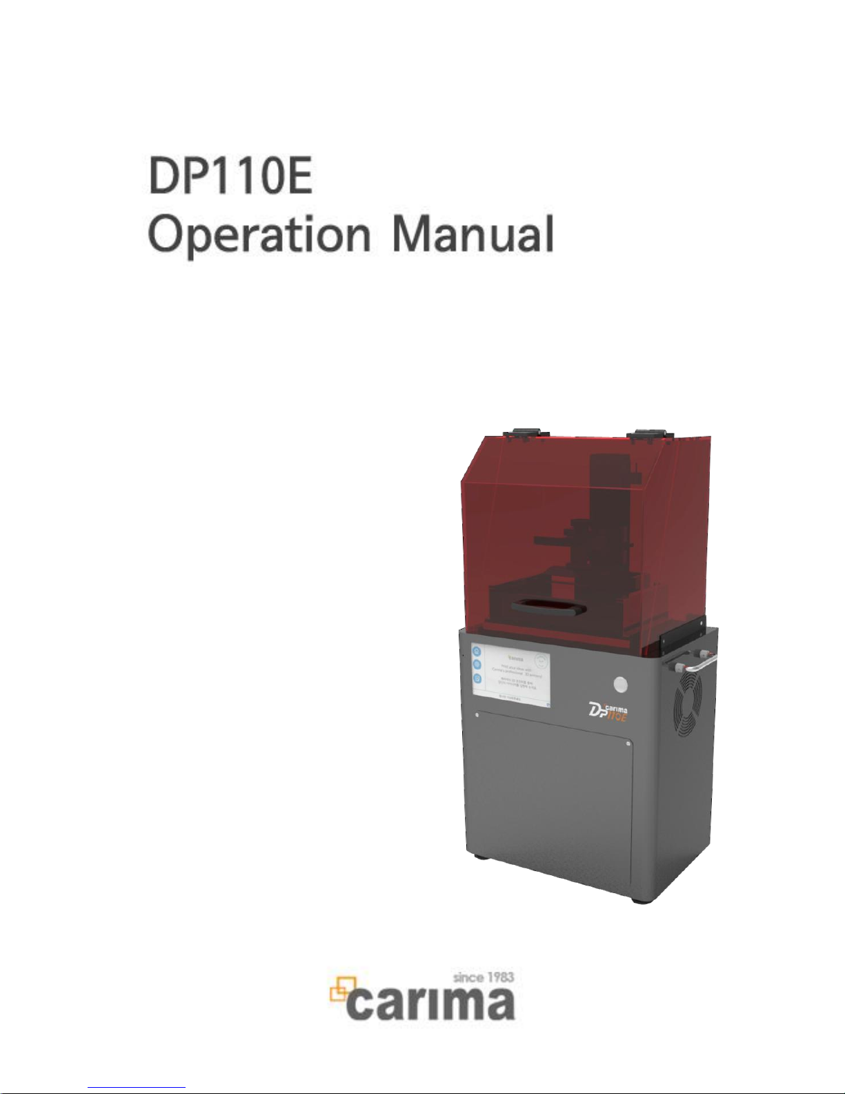
Operation Manual
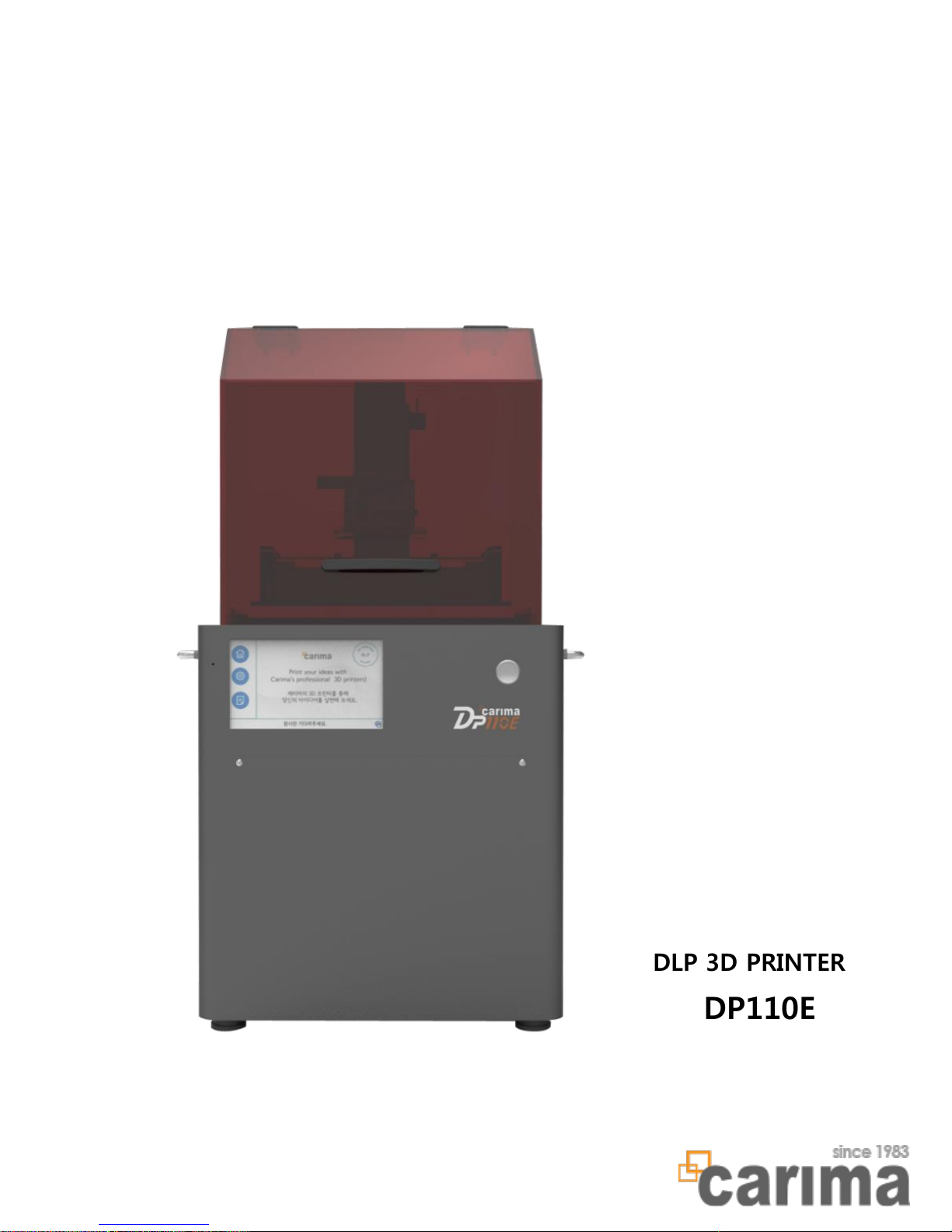
DLP 3D PRINTER
DP110E
Page 3

Table of Contents
1. Product Warranty
2. Safety precautions
3. Product Information
Specification, Consumables, Features
4. Names of Parts
5. How to Attach & Detach Tray
6. How to Detach & Attach Build Plate
7. How to Refill Resin
8. Amount of Resin Refill
9. VAT check
10. Maintenance
LED error messages, maintenance
11. DLP engine Lamp Replacement
1
2
4
6
7
8
9
10
11
12
15
Equipment Operation Manual
Page 4

1
Product Warranty
Thank you for your purchase.
The product is made from precise parts and managed by our quality control.
Carima warrants the product in accordance with following terms If the product
fails during normal use.
Warranty terms
1. If a defect arises with regard to the product during the warranty period,
CARIMA will repair or replace the defective parts of the product with new parts.
2. The warranty period applies for a period of 6 months from the date the Product was
first installed by a consumer.
3. Please contact us at the following numbers.
4. Please keep the original warranty card for future service request.
Exclusions and Limitations
1. If the product or Accessory malfunctions after the Warranty Period expires,
there is no warranty of any kind.
2. It doesn't apply to damage caused by operating the product outside
3. It doesn't apply to damage caused by accident, abuse, miuse, flood,fire,earthquake,
or under abnormal conditions
4. It doesn't apply to the Product damaged in shipping, transit, or on-site handling
during installation.
5. It doesn't apply to a product or part that has been modified to alter functionality
without the written permission of carima
6. If things including item description, installation date, signature are removed, Carima
is not responsible for the loss.
▶ During the warranty period, Carima will either repair or replace
any defective product at no charge.
▶ If a defect arises in the product after warranty period or in the
event of warranty exclusions, we may charge you a fee.
Please contact us for support at +82-2-3663- 8877
Installation date : . . .
Item description :_____________________________________________
Page 5

2
Safety precautions
- Read this manual carefully for proper handling and operation, before
installing, operating, maintaining and inspecting.
- It is designed to help ensure your own personal safety and to help protect your
equipemnt from potential damage.
- Failure to observe the safety notes may lead to serious injuries and to significant
damages to the system.
! Place the machine in well-ventilated place due to smell of the resin.
! Do not insert tools or parts of body into machine during the printing process.
! Never look directly into light beam in order to protect your eyes.
! Never use gasoline for printing. Please keep it away from the machine.
Also, 3D prints or resin residue shouldn't be swallowed, as It could causedisorientation
and suffocation.
! Stop the printer from processing and take the resin tank out not to overflow resin. and
then turn off the machine and move it.
! Do not turn power switch off when it's on. It reduces life span of engine and could be
one of errors. Get it ended as given in manual
! Putting some of liquid or metal pieces into printer is harmful for fire disease or
electric shock. Also, Do not operate the machine with wet hands protecting from fire or
electric shock.
! Do not ruin main power of printer. Neither change or ruin USB cables or supply power
raised from outside.
! Carefully choose place for installation protecting from pet or child injuries made by
printer
! Standard accessories include sharp tools such as cutter or nipper. Be careful not to cut
yourself on any sharp edges.
! The space inside machine is designed to be taken up by light of engine.
please do not insert anything else inside.
! Protect the machine from dampnes, such as rain and now, and dusty weather.
! Install and operate the machine on a flat level and dry surface. Kepp the machine away
from flammable liquids, gases, and aerosols.
! Do not impose excessive force on the machine.The external housing of your machine
may be damaged Also, Read all instructions before using the machine.
Page 6

Use of resin
! Be careful about resin from contacting skin or body part.
- If in contact, rinse in running water and make sure to wear gloves during work.
Replacement of resin
Lifetime of optical engine
3
! Remove alien substances and scraps at the bottom of tray.
- Remaining scraps may have adverse effects on the output.
! After replacing resin, stir well before use since precipitates can be formed.
Cleaning of build plate and tray
! Check for alien substances and scraps on build plate and tray every time.
- Remaining scraps may have adverse effects on the output.
- Regular management and cleaning of tray are necessary.
! Coating can be damaged if the tray is cleaned with a sharp object.
- Use a spatula or dry cotton cloth as cleaning tool.
! Poor cleaning can lead to poor quality of output and lifting or cracking of floor.
Lifetime of optical engine lamp is 3,000 ours, and brightness of the lamp can be
reduced by exceeding its lifetime. Replace the lamp after using it for 3,000 hours
to increase quality of output.
Preparation for A/S request
Record error situation, interior of the printer, and LCD display as photograph or
video.
- A/S can be much easier if the user explains the situation clearly.
Page 7
Product Information
Model Name
DP110E
Resolution of DLP engine
1024 x 768
Build size (mm)
110 x 82 x 190
Layer thickness (mm)
0.025 [0.025/0.05/0.075/0.1 (4 steps)]
X,Y Resolution
100μm
Product size (mm)
380 x 255 x 743
Product weight (kg)
19
Rating
100~240V, 50/60Hz, 2.5A, 260W
Material used
ACRYLIC
System control
Control using touch-type embedded screen included
Environment
18℃ ~ 26℃ (temperature) / 20% ~ 50% (humidity)
1. Product Spec
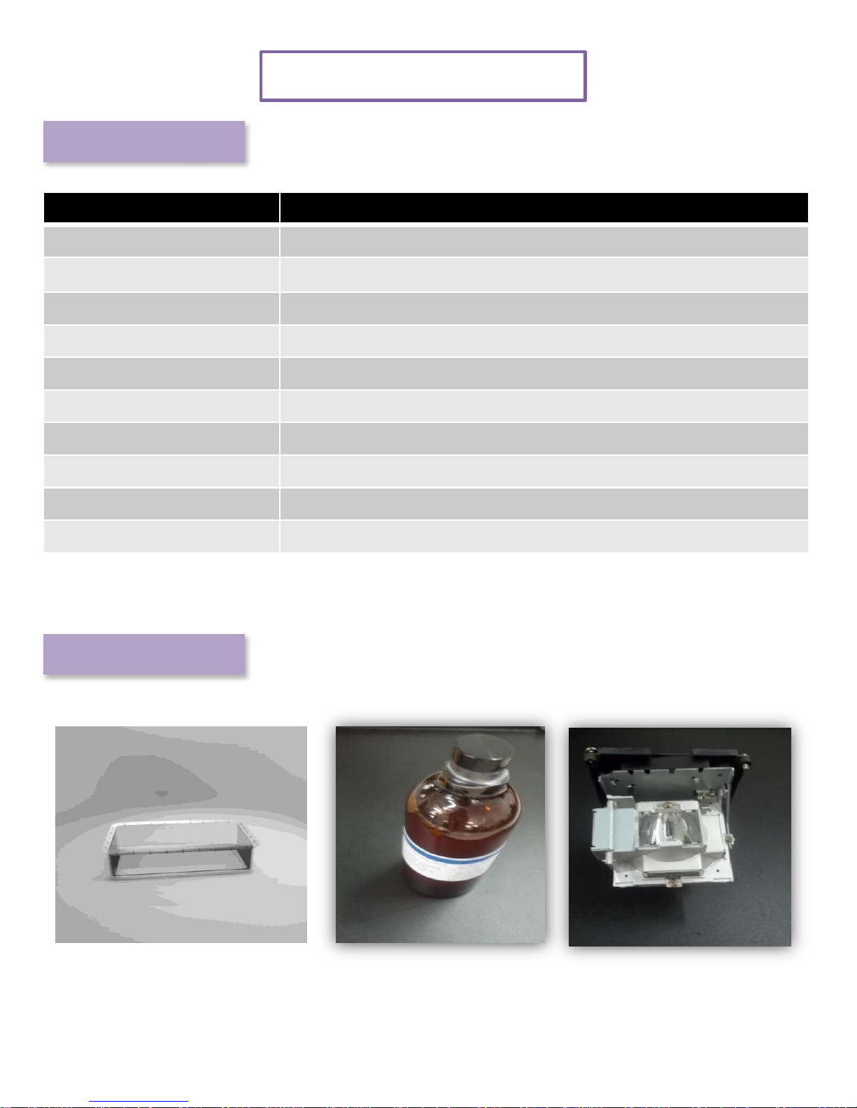
2. Consumables
[Special VAT]
[RESIN]
[LAMP]
4
Page 8
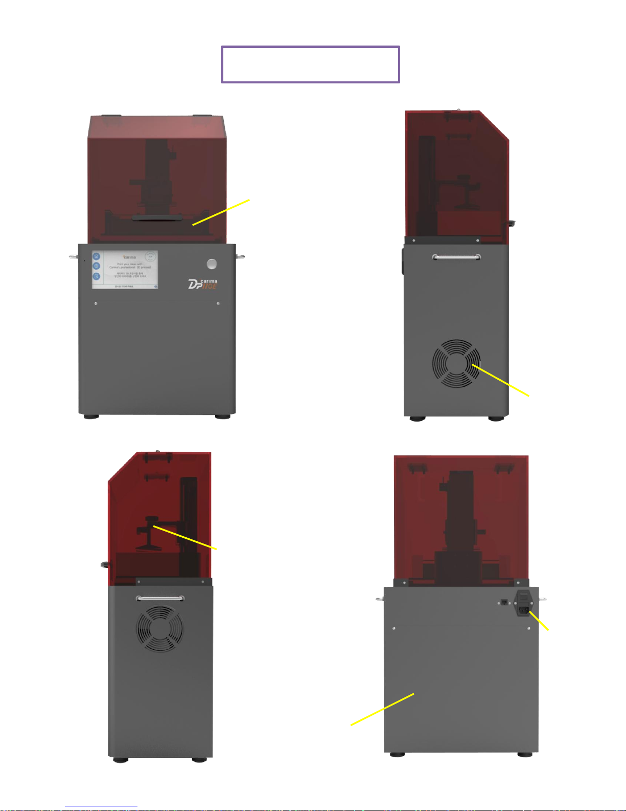
Names of Parts
[Front] [Right side]
[Back]
DLP engine
Tray
Fan
Power
button
Build
plate
[Left side]
5
Page 9
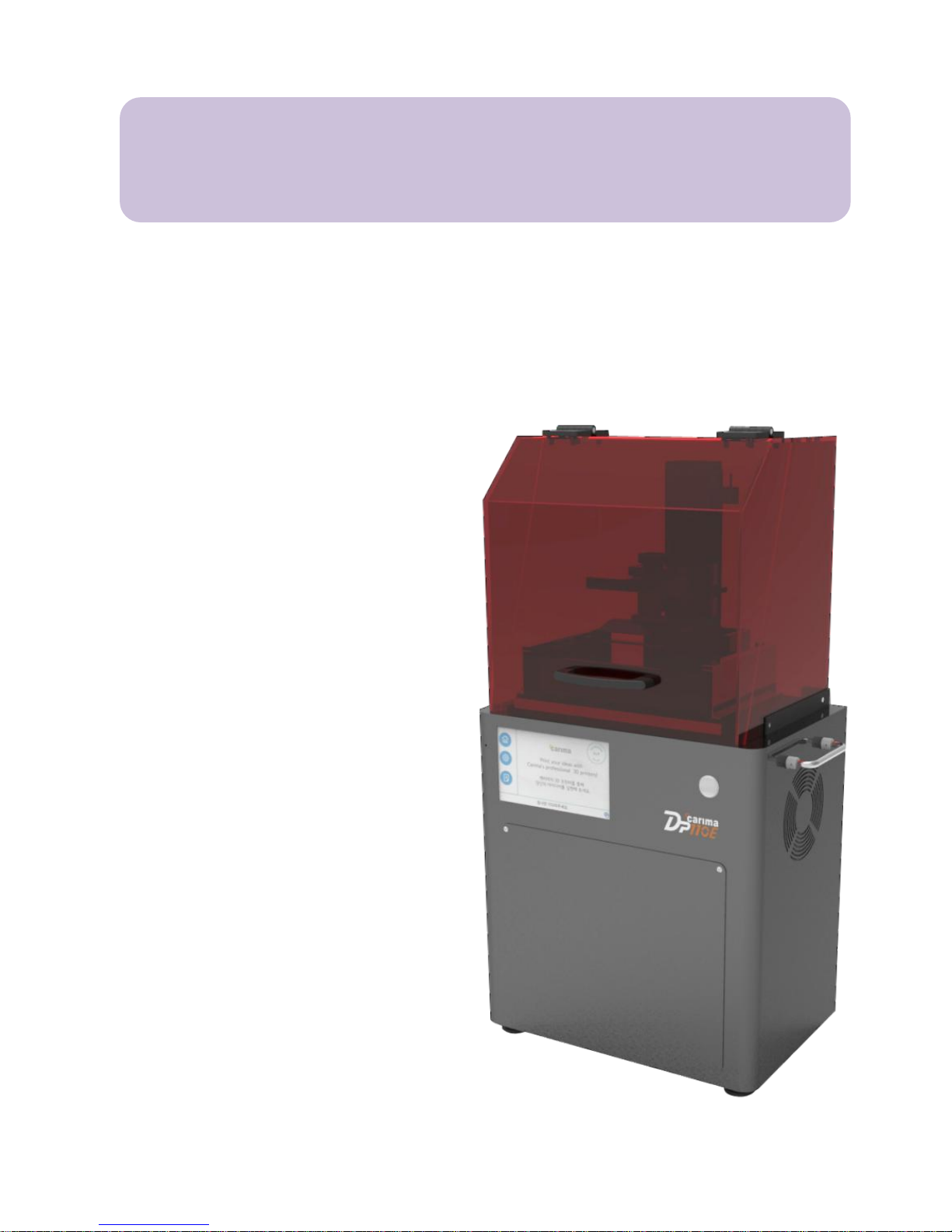
Equipment Operation Manual
DLP 3D PRINTER DP110E
Page 10
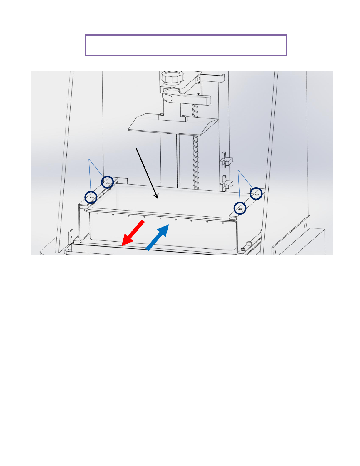
How to Attach & Detach Tray
7
Tray
1. Since the tray is pressed down by spring devices, pull the tray out.
(Be careful when pulling out the tray as resin inside can overflow
and stain the equipment.)
2. Push in the reverse order to attach the tray.
The tray will make “clicking” sound with the spring devices.
(Be careful when pushing in the tray as resin inside can overflow
and stain the equipment.)
Spring devices
Spring devices
Page 11

How to Detach & Attach Build Plate
8
Build plate lock knob
Build plate
Build plate handle
Loosen
When printing is done, loosen the build plate to detach it by rotating
build plate lock knob counterclockwise. Grab build plate handle and
take out. Reverse the order when attaching the build plate.
Precaution
When detaching the build plate, resin on the build plate may fall off or
spatter over the exterior or equipment to damage or contaminate the
equipment. After removing output, the build plate must be wiped out
cleanly to remove any remaining resin.
Resin left intact for long time can harden and affect output.
Page 12
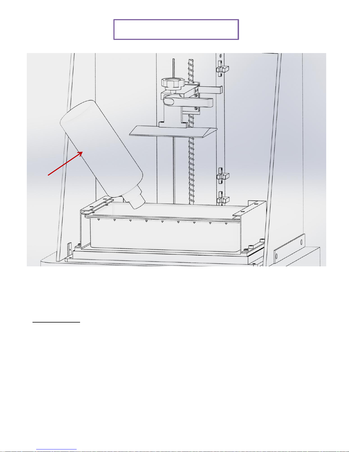
How to Refill Resin
9
Resin
Refill resin as shown in the figure.
Precaution
If possible, refill resin before printing. If it is inevitable to refill resin
while printing, press “pause” button and slowly add resin after the
work comes to a complete stop. Refilling resin while printing can
result in foams that have adverse effects on output.
Page 13
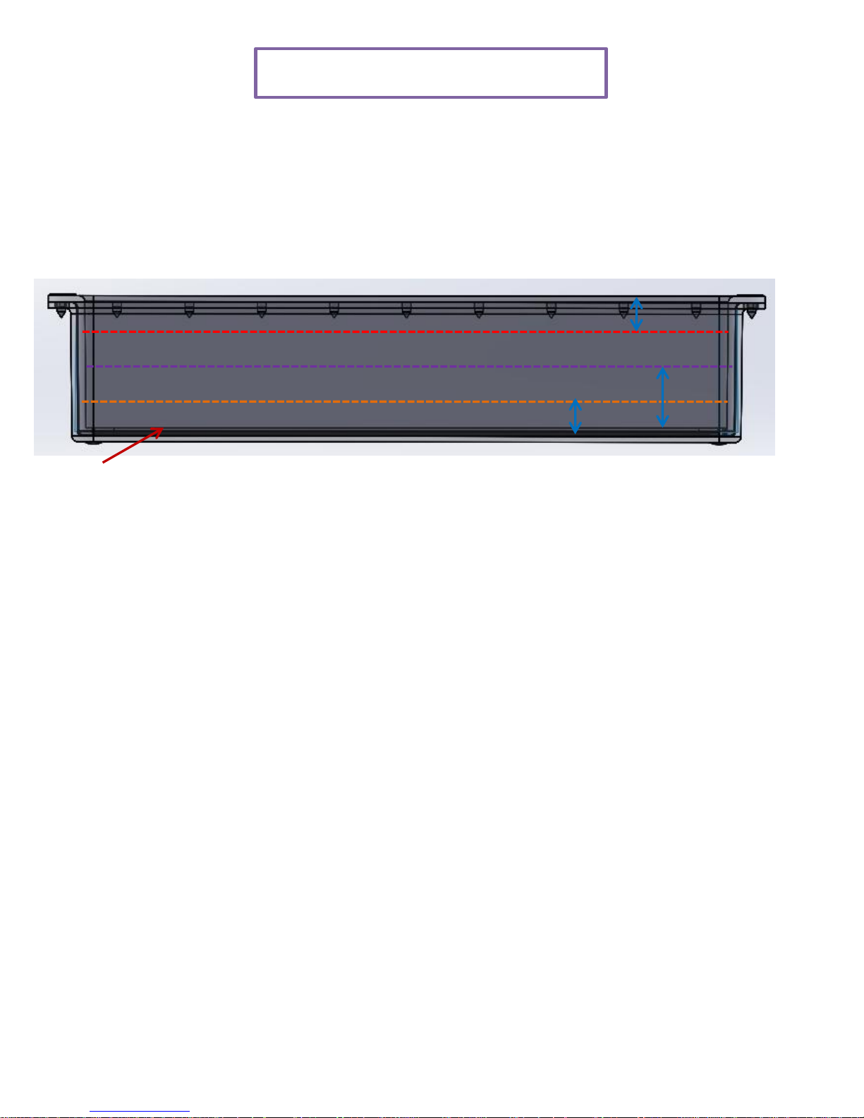
Amount of Resin Refill
10
Sheet surface
Max
5mm
10mm
5mm
Standard
Shell
In general, we recommend filling resin between shell line (250g) and
standard line (500g). Do not exceed max line (800g) when printing
large output.
When filling resin above the max line, resin can flow over the tray with
up-down motion of motor depending on shape of output.
Page 14
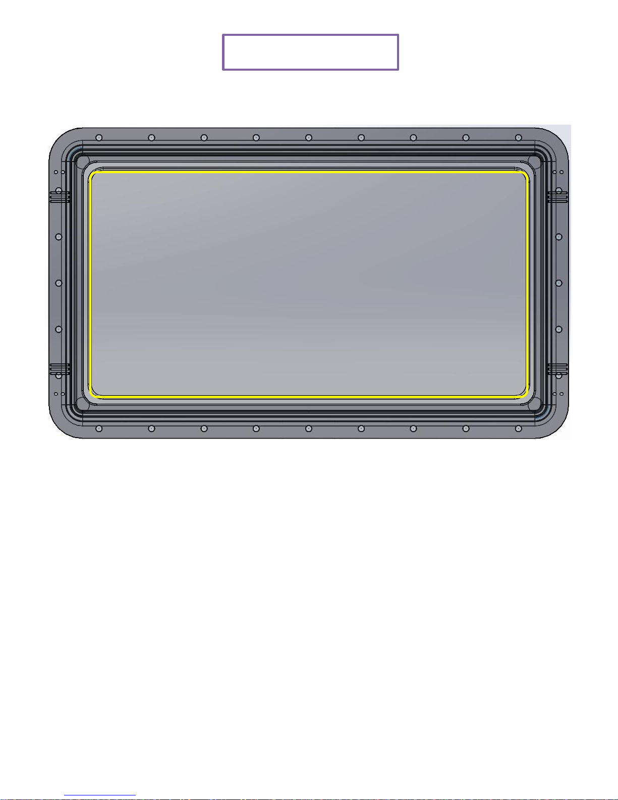
VAT Check
11
Surface of VAT sheet shows holes, ripping and loosening. These
are natural phenomena that appear when it is used for long time.
When the sheet surface has hole or ripping, resin will enter into
the hole or ripping and result in printing failure. Attach a new VAT
in this case.
This appears in short time if surface of the sheet is scratched by
output or hardened scrap made carelessly by the user.
Page 15
12
Maintenance
Cleaning the dust and rubbish off the projector will help use the projector
without any malfunctions.
Warning:
1. Turn the projector off and unplug at least 30 minutes prior to cleaning
the projector. It may cause a serious burn if not.
2. Use a damp cloth. Be careful not to have any water seep into the
ventilation outlet.
3. If any water has penetrated into the projector while cleaning, leave it in
well ventilated area before connecting the power supply.
4. If a large amount water penetrated into the projector while cleaning,
please inquire for repair at the service center.
To clean the lens
Lens cleaning agent can be purchased from a lens store. Clean the lens as
the following instructions.
1. Wet a clean and soft cloth with a small amount of lens leaning agent.
(Do not apply the lens cleaning agent directly on the lens.)
2. Clean the lens in light circular motion.
Notes:
1. Do no use any polishing agent or solvent.
2. Using detergent on the project case may cause discoloring or color
fading.
To clean the case
Please clean the projector case as the following instructions.
1. Clean any dust with a clean damp cloth.
2. Wet a cloth with warm water with soft detergent added in it such as
dishwashing liquid to wipe the case with.
3. Remove any detergent on the cloth and wipe the projector again.
Notes:
1. Do not use polishing agent or detergent containing alcohol since it
may cause discoloring or color fading.
Page 16
Control Screen Manual
DLP 3D PRINTER DP110E
Page 17

1. (DP110) LCD Screen Information
2. Initial Setting
1) Zero Setting
3. System Control
1) Motor Control
2) Engine Control
4. Print Setting
5. Preparation for Printing
6. Start Printing
7. Pause Printing
8. Stop Printing
9. Printing Option
1) Temporary Check on Mold
2) Auto Exit
10. Exit System
Control Screen Manual
Page 18
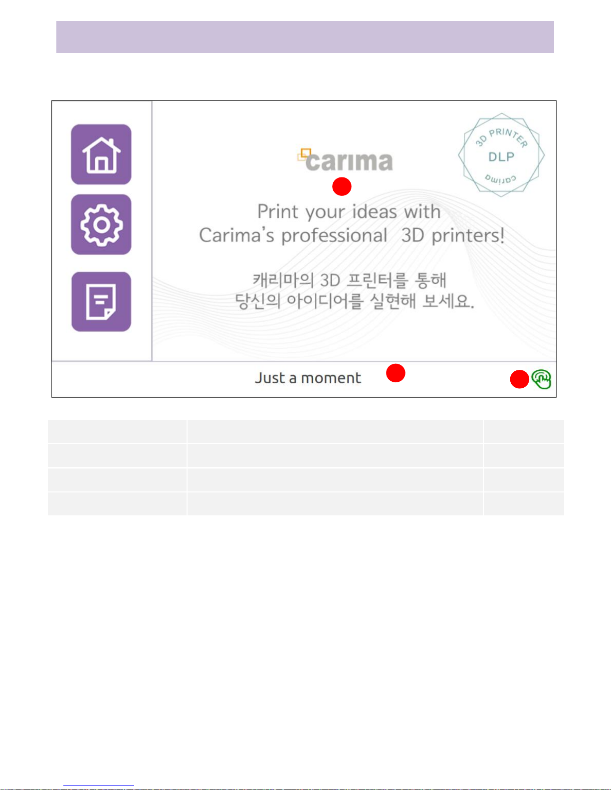
Ch1. LCD Screen Information
Composition of Loading Screen
Function
Description
Page
① Loading Image
Please wait a moment until home screen appears.
② Status Message
This pops a message to display current status.
③ Exit Button
This exits the system.
1
2
3
15
Page 19
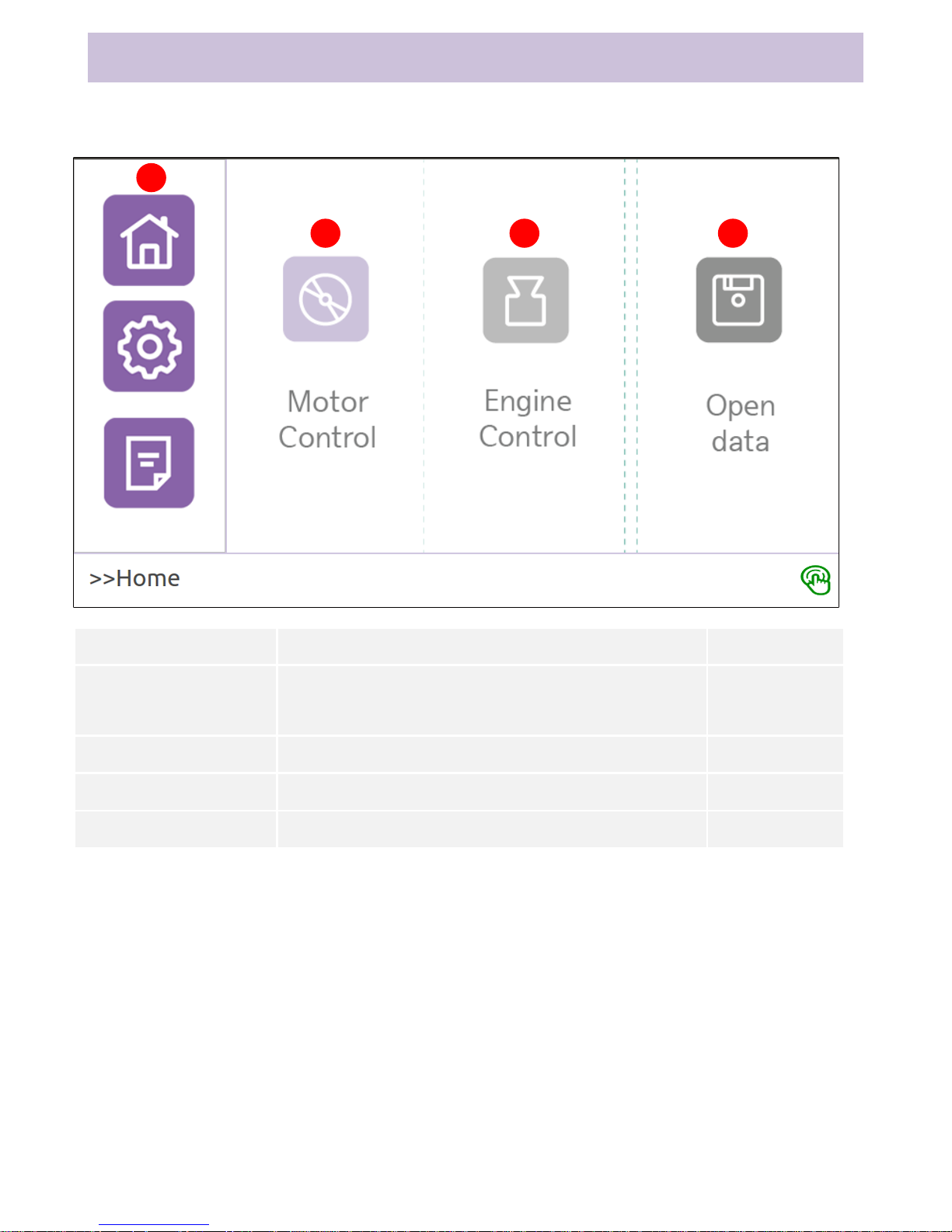
Composition of Home Screen
1
2 3 4
Function
Description
Page
① Home, Setting,
Information Tabs
These tabs move to Home, Setting and
Information menus.
② Motor Control
This moves to Motor Control menu.
③ Engine Control
This moves to Engine Control menu.
④ Open Data
This shows list of data to be printed.
Ch1. LCD Screen Information
16
Page 20
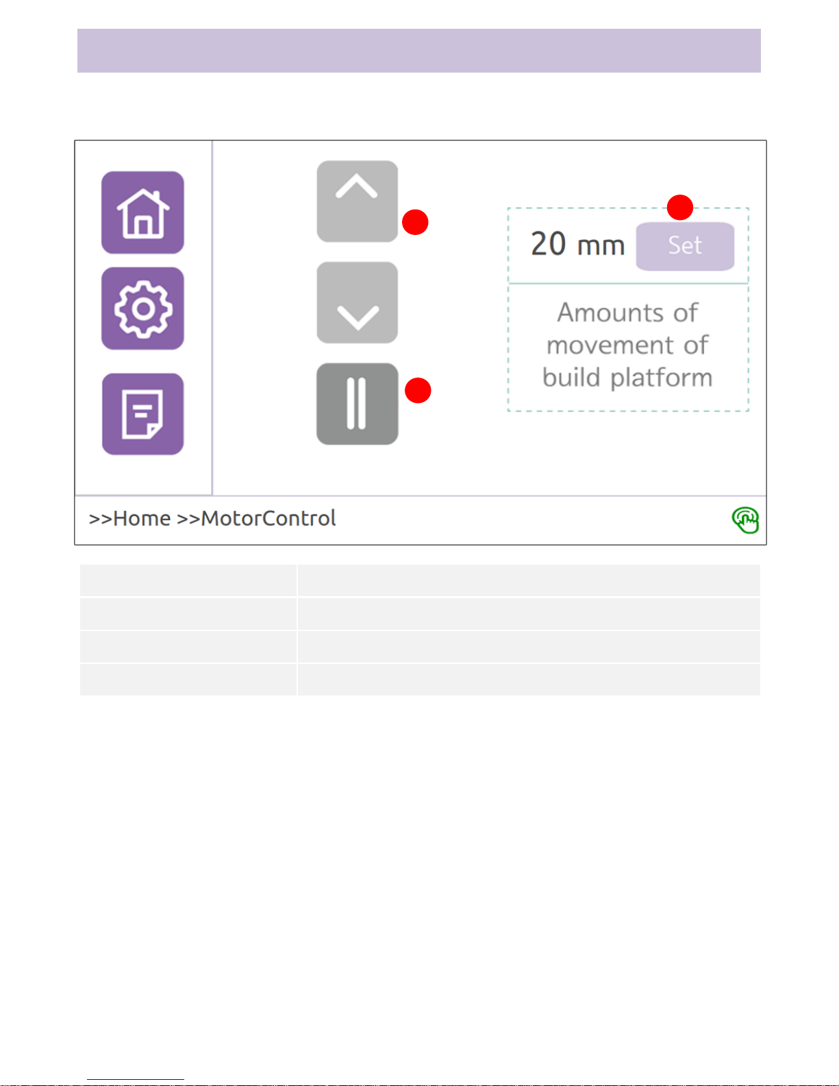
Composition of Motor Control Screen
1
2
3
Function
Description
① ↑↓
The build plate moves up and down.
② ||
The build plate stops.
③ Setting
This sets movement distance of the build plate.
Ch1. LCD Screen Information
17
Page 21
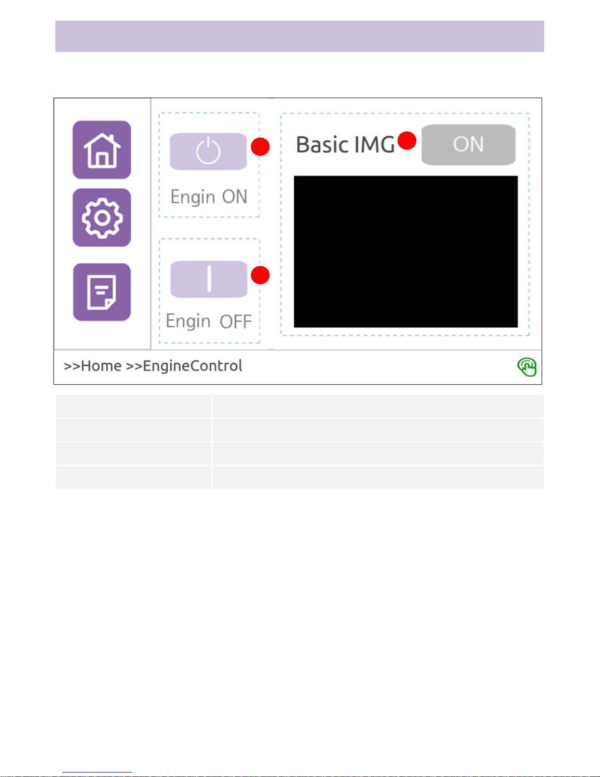
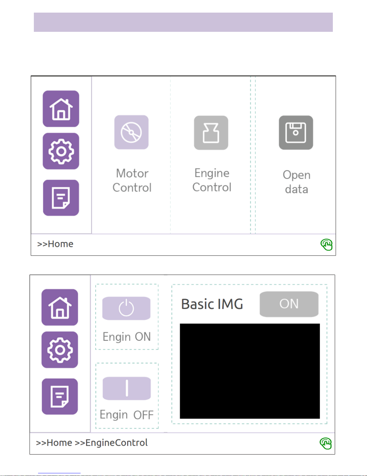
Composition of Engine Control Screen
Function
Description
① Engine ON
Optical engine ON
② Engine OFF
Optical engine OFF
③ View Default Image
Optical engine projects default image.
Ch1. LCD Screen Information
1
2
3
18
Page 22
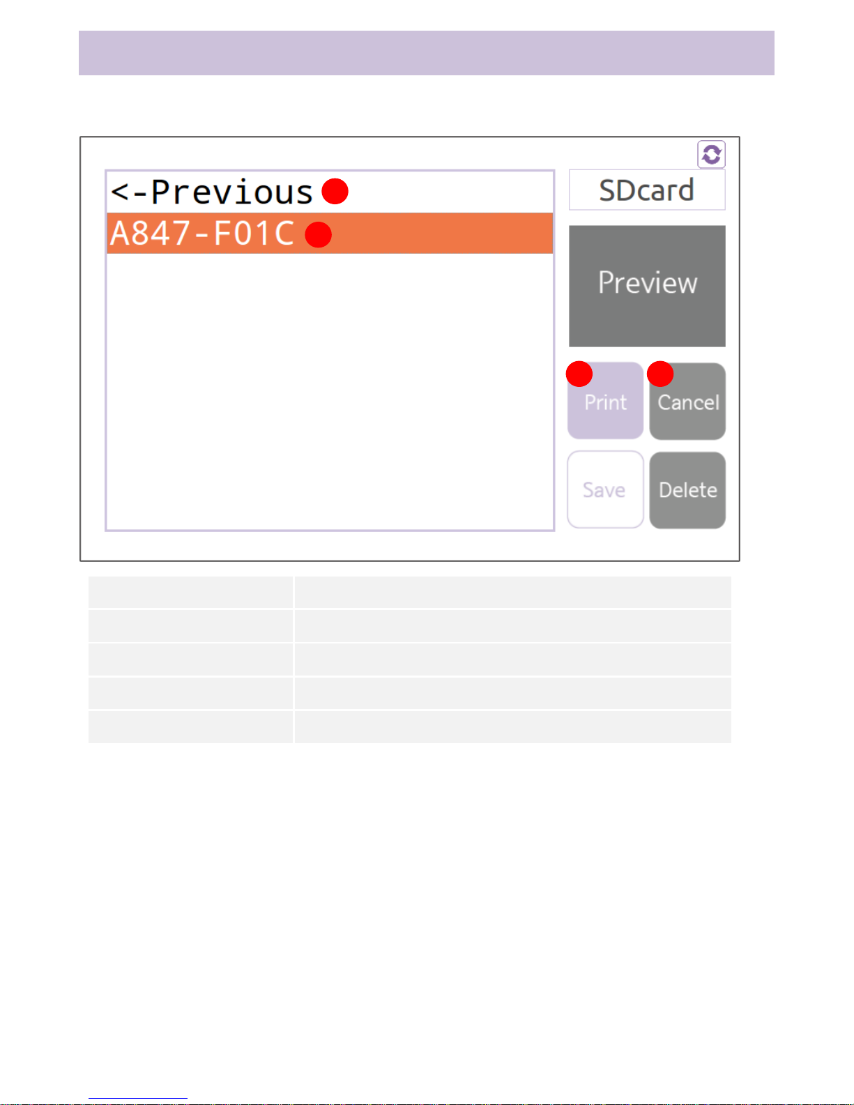
Composition of Data Open Screen
1
1
2
3
4
Function
Description
①Previous
This moves to previous folder.
② Folder List
This displays name of the folder list.
③ Print
Press Print to move to printing mode screen.
④ Cancel
Press Cancel to return to previous screen.
3
Ch1. LCD Screen Information
19
Page 23
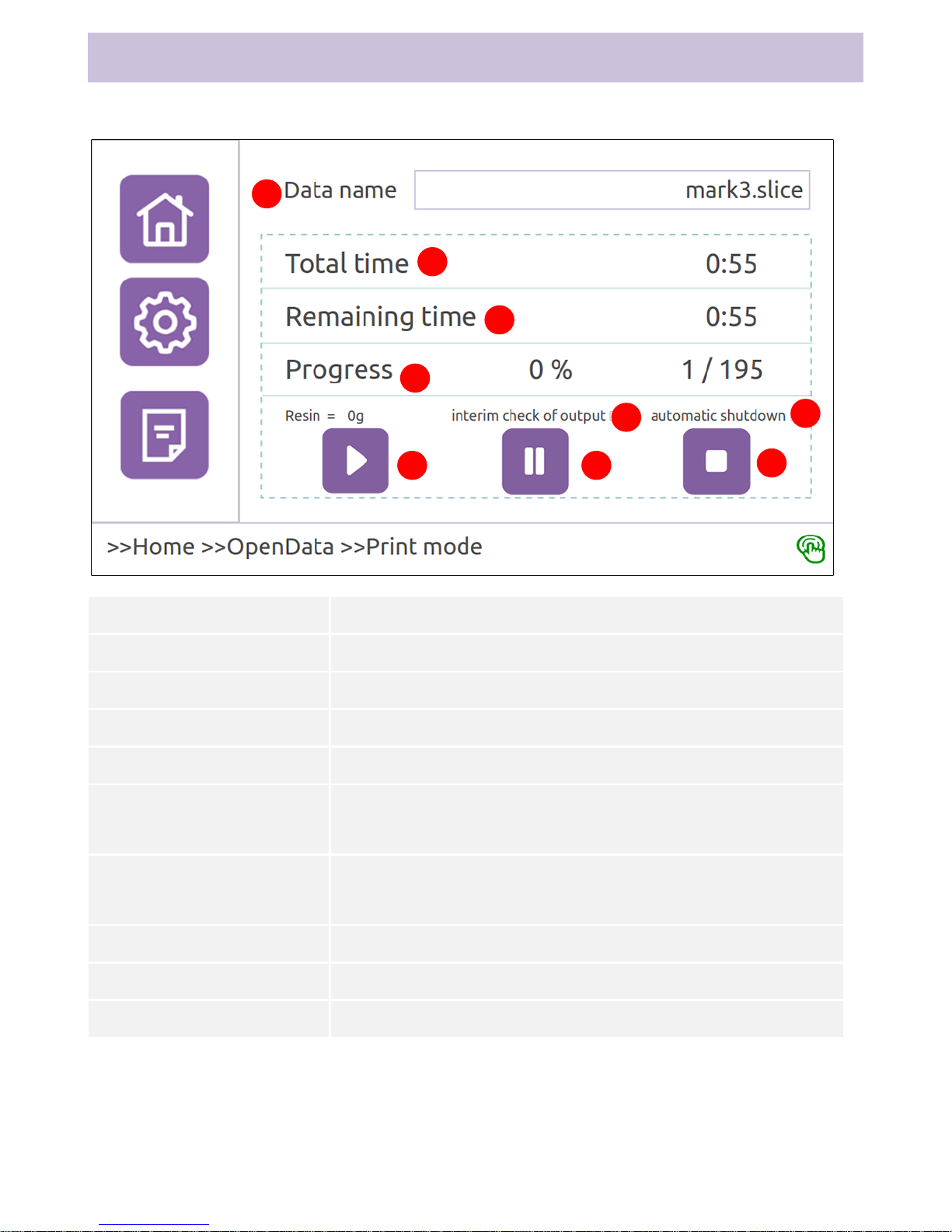
Composition of Printing Mode Screen
1
2
3
5
4
Function
Description
① File name
This is name of the file being printed.
② Total time
This is total time taken to print.
③ Remaining time
This is remaining time until completion of printing.
④ Progress
This displays current progress rate and layer.
➄ Temporary Check on
Mold
This function is used to check the mold while molding.
(Refer to description on Print Setting)
➅ Auto Exit
This function exits the printer automatically once molding is
complete.
➆ Start
Starts printing
➇ Pause
Pauses printing
➈ Stop
Stops printing
6
7 8
9
Ch1. LCD Screen Information
20
Page 24
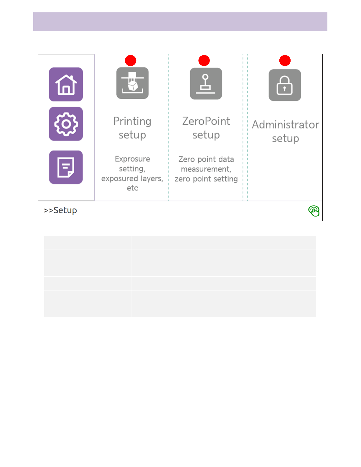
Composition of Setting Screen
1 2 3
Function
Description
① Print Setting
This sets setting values (exposure time and exposure layer)
necessary for printing.
② Zero Setting
This sets zero point on Z axis for stable printing.
③ Administrator Setting
This checks and sets printer settings (system, optical,
password, etc.).
Ch1. LCD Screen Information
21
Page 25
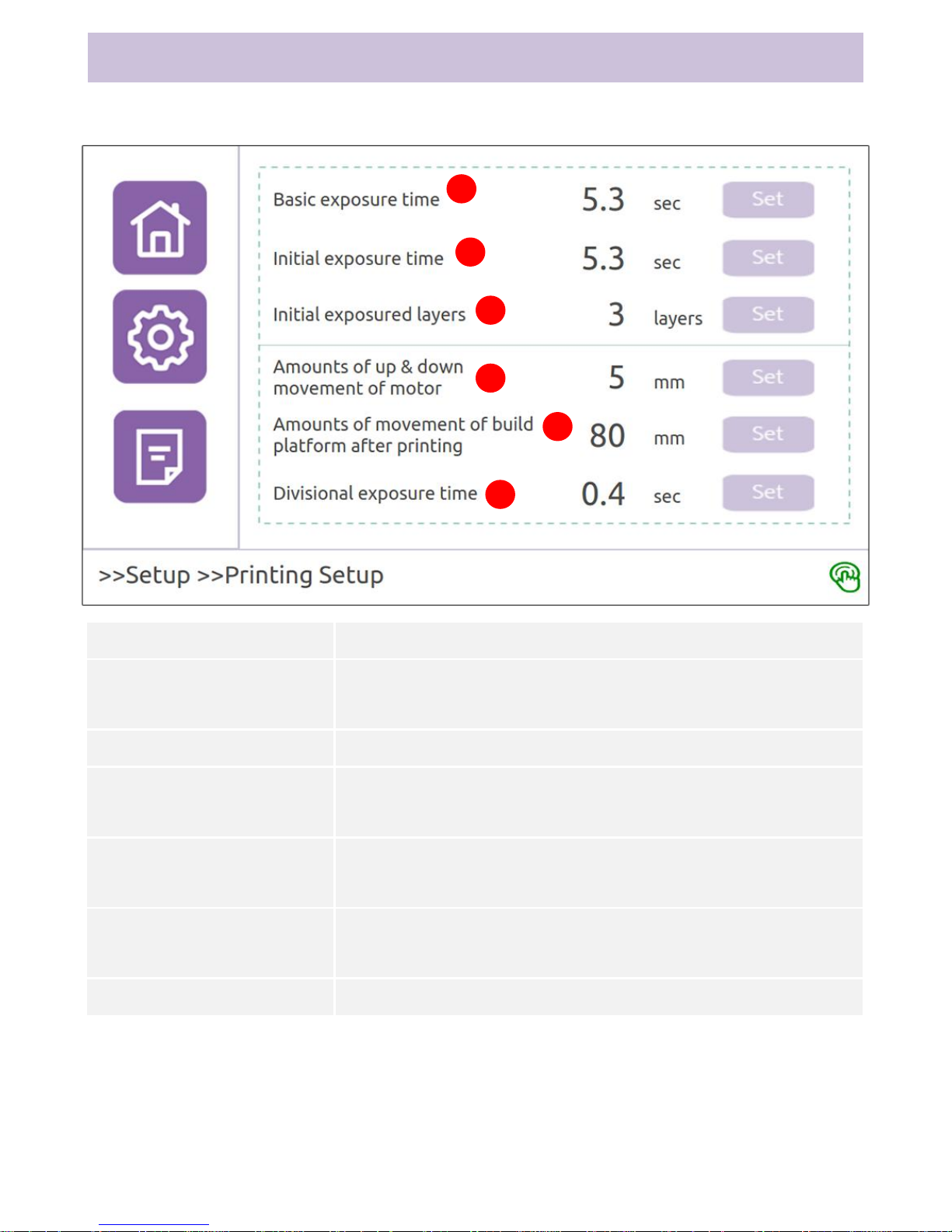
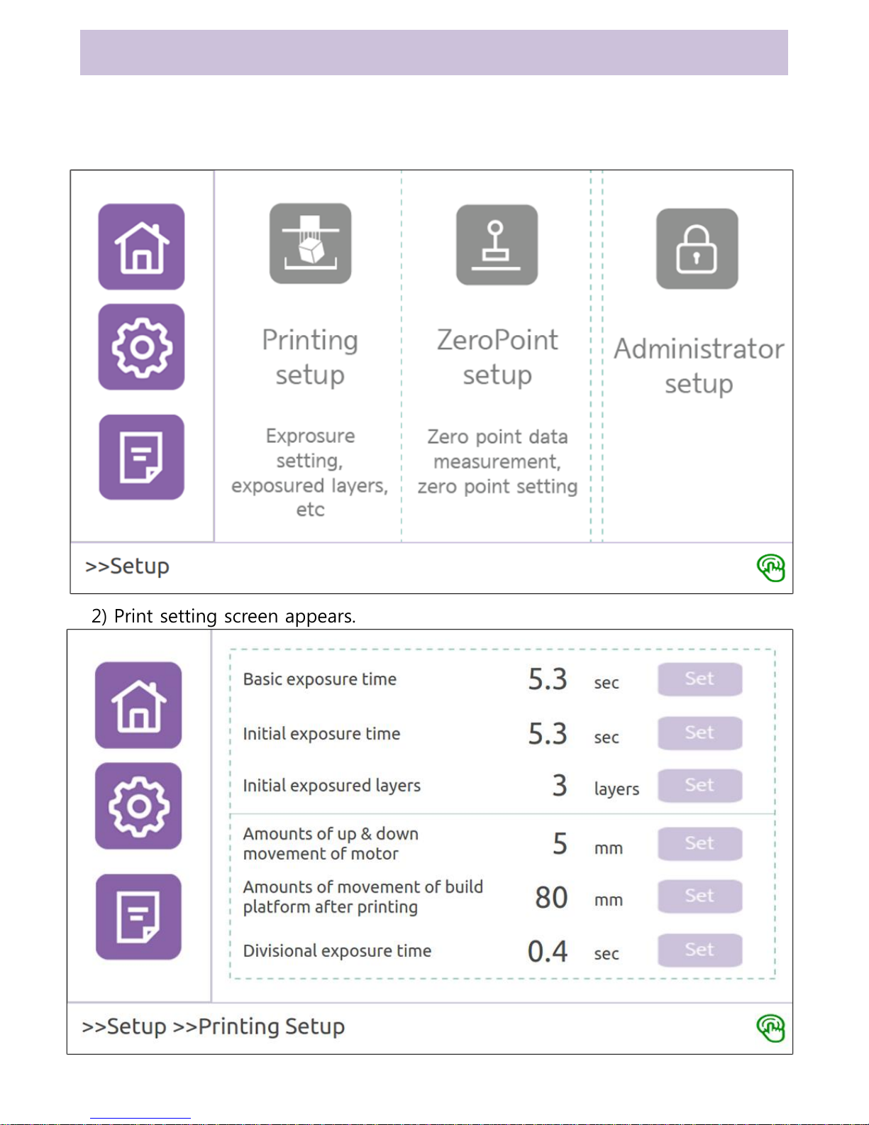
Composition of Print Setting Screen
1
2
3
Function
Description
① Default Exposure Time
This refers to default time for which output image is exposed in
the optical engine.
② Initial Exposure Time
This refers to exposure time to attach output to the build plate.
③ Initial Exposure Layer
This refers to the number of layers to which initial exposure time
is to be applied.
④ Movement of Build Plate
While Building
This refers to movement of the build plate on every layer.
➄ Movement of Build Plate
After Building
This refers to movement of the build plate after completion of
building.
➅ Split Exposure Time
This refers to split exposure time.
4
5
6
Ch1. LCD Screen Information
22
Page 26
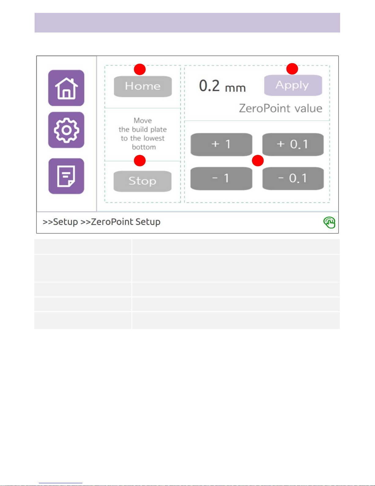
Composition of Zero Setting Screen
1
2 3
4
Function
Description
① Home
Moves to the lowest point of the build plate
(starting point of zero setting)
② Stop
Stops the build plate
③ +1, -1. +0.1, -0.1
Moves the build plate by the indicated value
④ Apply Zero
Applies and saves zero point
Ch1. LCD Screen Information
23
Page 27
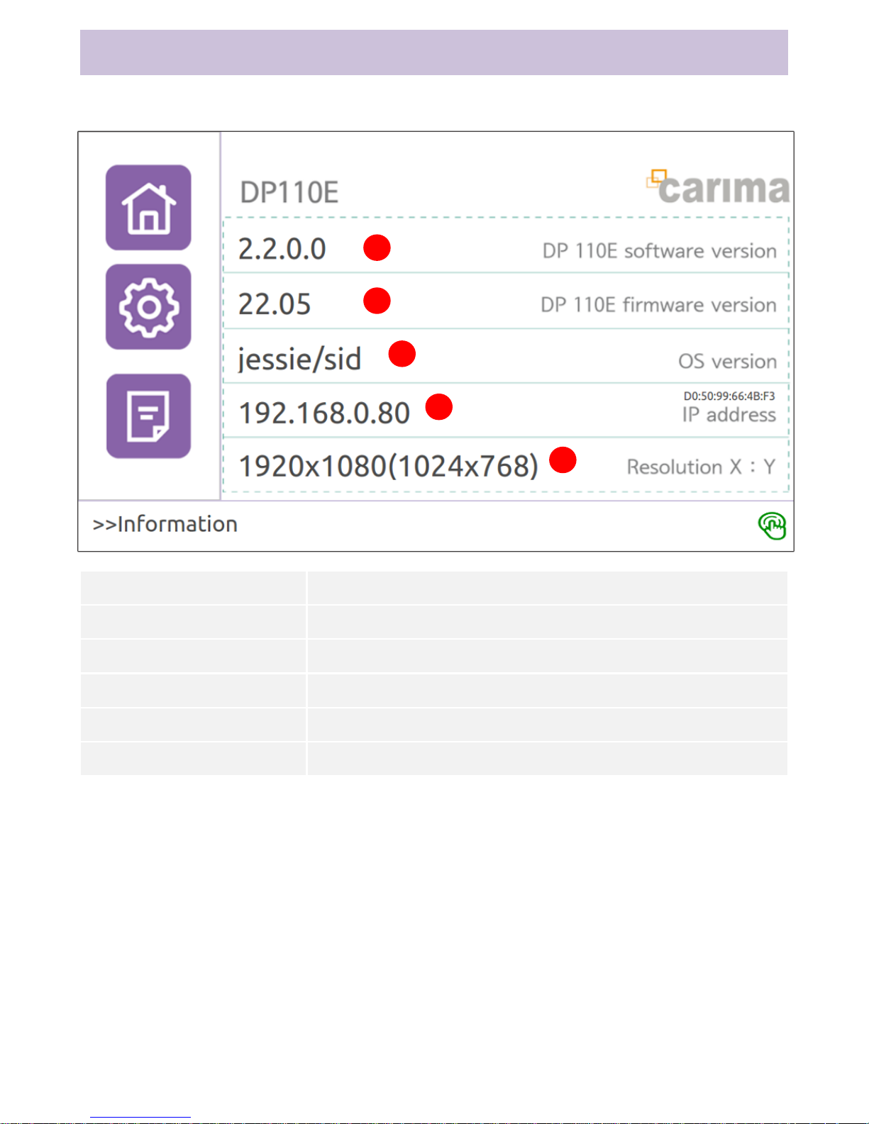
Composition of Information Screen
1
2
3
Function
Description
① S/W Version
This shows software version.
② F/W Version
This shows firmware version.
③ OS Version
This shows OS version.
④ IP Address
This displays internal IP address.
⑤ Resolution
This shows engine resolution (actual resolution).
4
5
Ch1. LCD Screen Information
24
Page 28
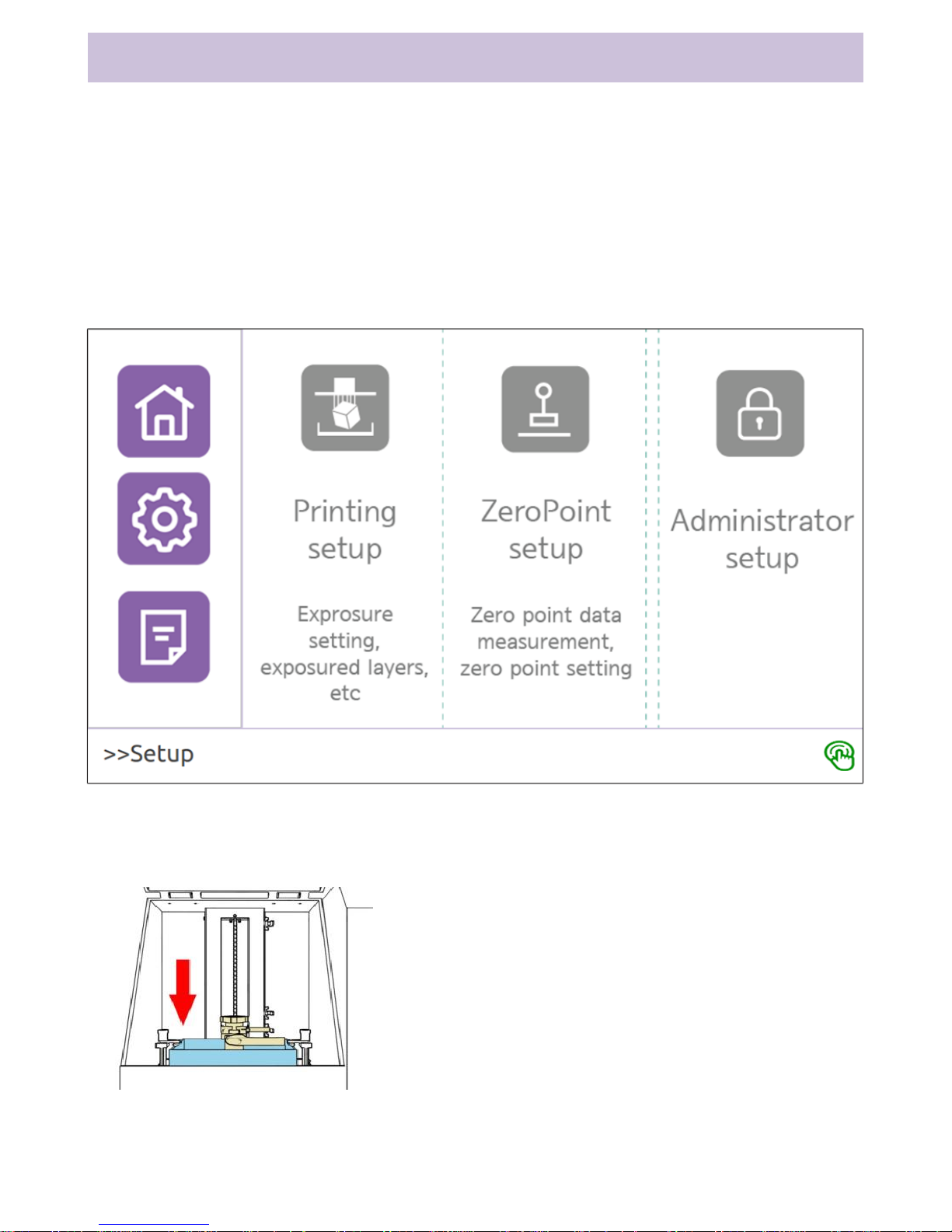
1. Zero Setting
Zero setting finds the accurate point at which the build plate contacts the
tray surface at the beginning of printing.
* Our products are delivered to customers with zero setting completed.
Therefore, this setting is unnecessary unless there is a problem in the setting.
1) Select ‘Setting’ on the left tab menu to show Print Setting, Zero Setting
and Administrator Setting. Select Zero Setting.
2) Zero setting screen appears.
3) Zero setting method
1. Press Home button.
- The build plate moves to sensor point
near the tray (starting point of zero
setting).
Ch2. Initial Setting
25
Page 29
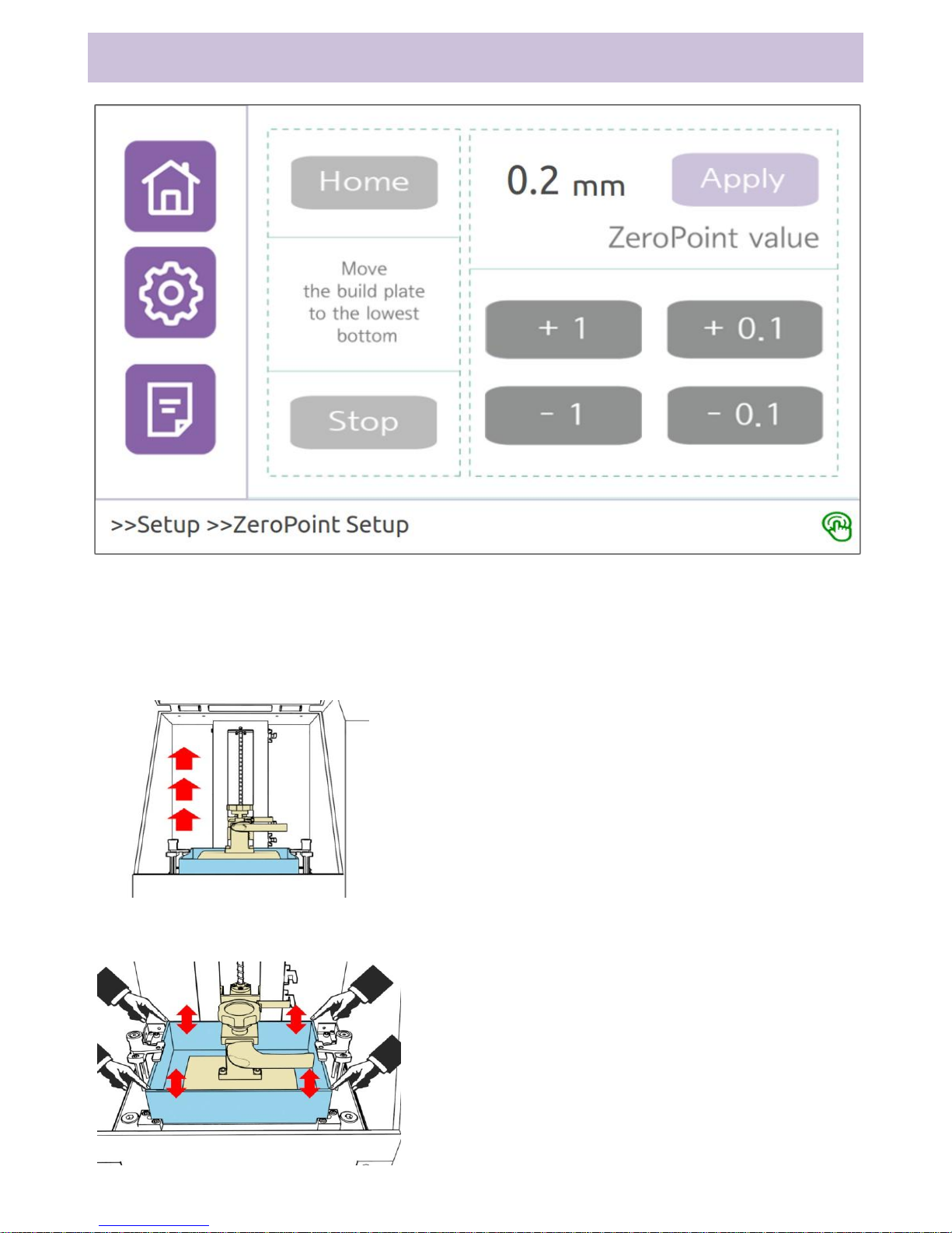
Ch2. Initial Setting
- Zero point is reset to 0mm. (The reset value is not saved unless Apply button
is pressed.)
- The tray is stopped while being pressed.
Use 2, +1, +0.1, -1 and -0.1 buttons to adjust position of the build plate.
- Adjust position of the build plate until
pressing of the tray is removed.
- Pick up the corner of the tray with hand and
shake it. Adjust the build plate when shaking
of the corner cannot be felt.
- Gap between the tray and the build
plate must be just enough to insert a
thin paper.
3. Zero point is displayed once adjustment
of the build plate is done. Click ‘Apply’
button to finish zero setting.
- ‘Apply’ button must be clicked to save
the value.
26
Page 30
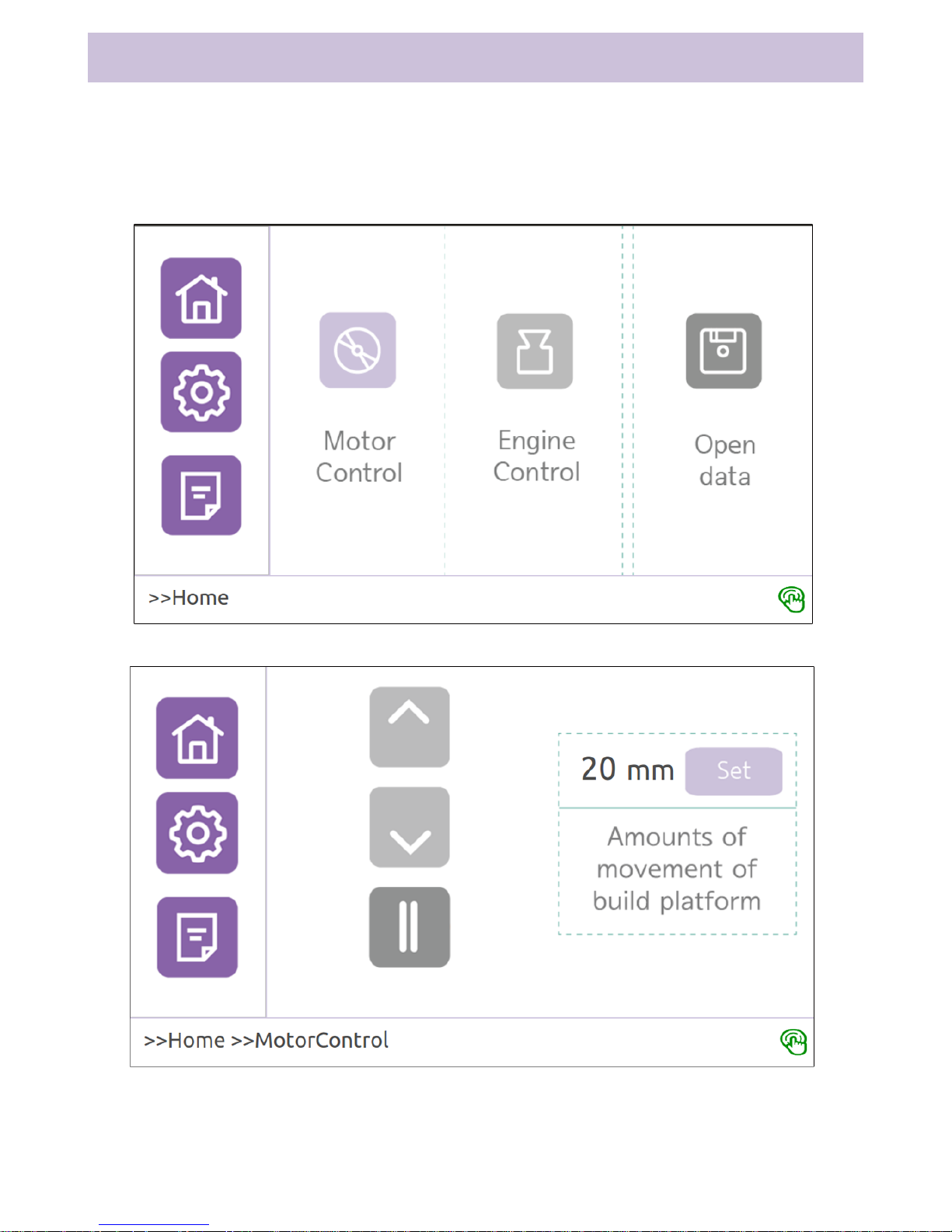
Ch3. System Control
This function is used to control the equipment manually and check problems in
the motor and the optical engine before printing starts.
1. Motor Control
1) Select ‘Home’ on the left tab menu to show Motor Control, Engine Control
and Open data items. Select Motor Control.
2) Motor control screen appears.
3) Motor control method
1. Use ↑, ↓ and || buttons to move the build plate.
- Use Setting button to adjust movement distance of the build plate.
- Movement distance of the build plate is 20mm with initial setting.
2. Problem in the motor can be determined through motor control.
27
Page 31
Ch3. System Control
2. Engine Control
1) Select ‘Home’ on the left tab menu to show Motor Control, Engine Control
and Open Data items. Select Engine Control.
2) Engine control screen appears.
28
Page 32

Ch3. System Control
3) Optical Engine Control Method
1. Engine ON and OFF buttons can be used to turn the optical engine ON/OFF.
- Since the optical engine is a lamp-type engine that cannot be turned
ON/OFF immediately and requires warm-up, it requires booting time from 20
seconds to 2 minutes.
- Do not turn OFF the power switch when the engine is turned ON. This can
reduce lifetime of the lamp.
- Turn OFF the printer according to the program exit procedure similar to
computer.
2. View Default Image button shows error in engine output and size of output.
- Use Hide button to deactivate View Default Image button.
3. Problem in the optical engine can be determined through engine control.
29
Page 33
Ch3. System Control
3. Print Setting
1) Select ‘Setting’ on the left tab menu to show Print Setting, Zero Setting and
Administrator Setting items. Select Print Setting.
2) Print setting screen appears.
30
Page 34

Ch3. System Control
3) Print Setting Know-how
1. Exposure time refers to time during which output image is exposed in the
optical engine when printing a layer. Long exposure time causes overhardening of output and short exposure time causes under-hardening. It is
necessary to enter accurate time for resin being used.
2. Initial exposure time should add 1~3 seconds to default exposure time.
3. If ‘Movement of Build Plate While Building’ is short, building time is
shortened. If movement distance is too short, it can have adverse effects on
output. This distance is 5~15mm in general.
4. ‘Movement of Build Plate After Building’ refers to distance by which the
build plate it lifted automatically after building. Value of 40~60mm is most
convenient.
5. Split exposure time refers to time that splits exposure time. Since light of
the optical engine contains high energy, long-time exposure has adverse
effects on the tray. Therefore, setting of split exposure time can lessen damage
on the tray. Value is 3~5 seconds in general. This function is deactivated by
setting split exposure time to 0.
31
Page 35
Ch3. System Control
5. Preparation for Printing
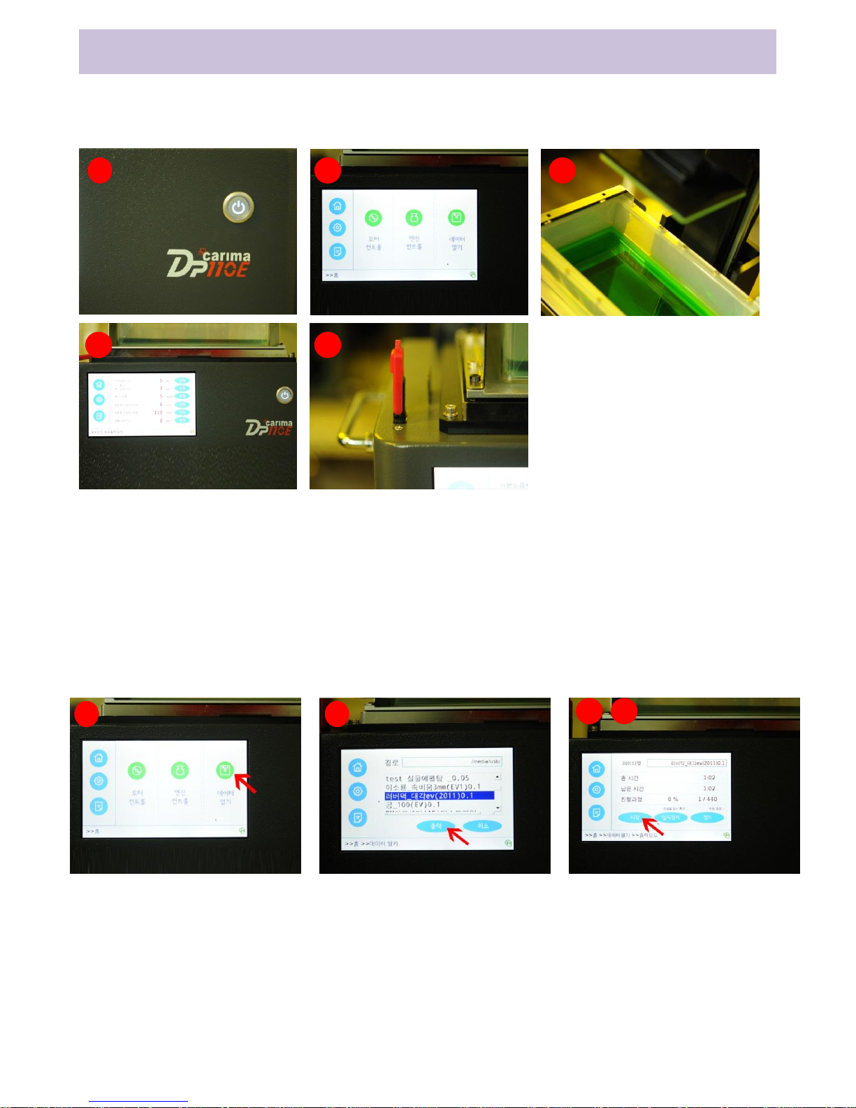
This is preparation for printing. Follow the instructions below.
6. Start Printing
This is the procedure to start printing. Follow the instructions below.
1. Select Open Data on Home screen.
2. Select data to be printed and click Print button.
3. Print data will be loaded.
4. Printing mode screen appears once loading of print data is done.
5. Click Start button on the printing mode screen to move the build plate to
the bottom and start printing.
32
1. Turn ON the 3D printer power switch and turn power ON.
2. Wait for a moment until Home screen appears from Login screen.
3. Check cleaning of VAT, cleaning of the build plate, existence of resin and
resin scraps.
4. Check accurate input of resin exposure time.
5. Insert USB with output data into the port.
1 2 3
4 5
1 2
4 5
Page 36
Ch3. System Control
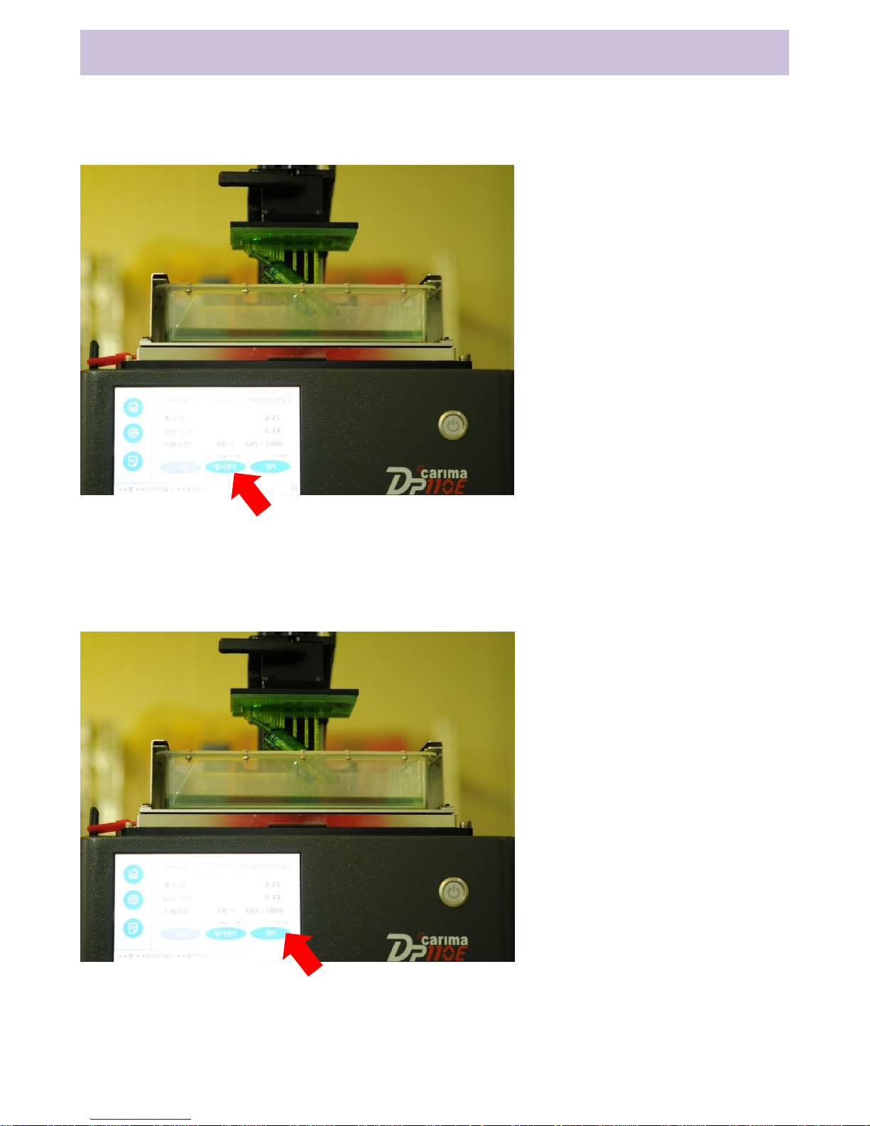
7. Pause Printing
Printing can be paused.
8. Stop Printing
This explains how to stop printing.
33
1. Select Pause button while
printing.
2. Printing is paused when
the optical engine emits
light.
* Printing is not paused
immediately after selecting
Pause button in order to
maintain stable printing.
3. Press Pause button once
again after printing stops to
restart printing.
1. Select Stop button while
printing.
2. Confirmation message
appears. Select ‘OK’ button
to stop printing.
* When Stop button is
pressed while the optical
engine is emitting light,
printing will be stopped
after emission process.
Page 37

Ch3. System Control
9. Printing Option
1) Temporary Check on Mold
While printing, check ‘Temporary Check on Mold’ on the printing mode screen
and press Pause to check the output.
Press Pause again to return to previous printing position and restart printing.
This function cannot be used if printing is progressed over 140mm.
Summary) Temporary Check on Mold -> Click Pause -> Check the mold ->
Click Pause -> Restart printing
2) Auto Exit
While printing, check ‘Auto Exit’ item on the printing mode scree. Power of the
optical engine and the program are turned OFF automatically once printing is
done.
* In case of the optical engine, power is turned OFF after 20 seconds ~ 2
minutes for stabilization.
Summary) Auto Exit (check) -> Printing complete -> Run Auto Exit function
34
Page 38

Ch3. System Control
10. Exit System
Follow the given route to exit the program.
If the program is turned OFF while printing, it may have adverse effects on
lifetime of the optical engine. If possible, turn the program OFF after printing is
done.
1) Select ‘Power Icon’ at the bottom right corner to exit the program with
Auto Exit message.
2) Since the optical engine takes from 20 seconds to 2 minutes to be turned
OFF, lower the power switch after confirming the that optical engine turns OFF.
35
Page 39

36
Precautions for Post Work
Preparation for post work: Materials (cutter blade, spatula, cleaning
alcohol, pincers, toothbrush)
<Precautions>
- Use of cutter blade: The mold can be damaged if taken off by hand or
ordinary knife. The build plate can be damaged if it adsorbs strongly
to the build plate.
- Alcohol: Only use pure ethanol. Never inhale alcohol since it is
hazardous.
- Air compressor: Use an air compressor with 1 horsepower or above so
that remaining residues can be wiped out sufficiently. If the
compressor is not ready, dry alcohol completely at room temperature.
- Cleaning time: Since the mold can be deformed if immersed in alcohol
for long time, make sure to clean it quickly after detachment.
- Hardening time: Hardening is done in about 10 minutes since
secondary hardening (UV hardener) can cause bending or deformation
of thin mold.
- Treatment of waste after printing: Wastes are separated into liquid and
solid. Liquid is entrusted to a waste treatment company, and solid is
treated as general waste. (Refer to the back page)
Page 40
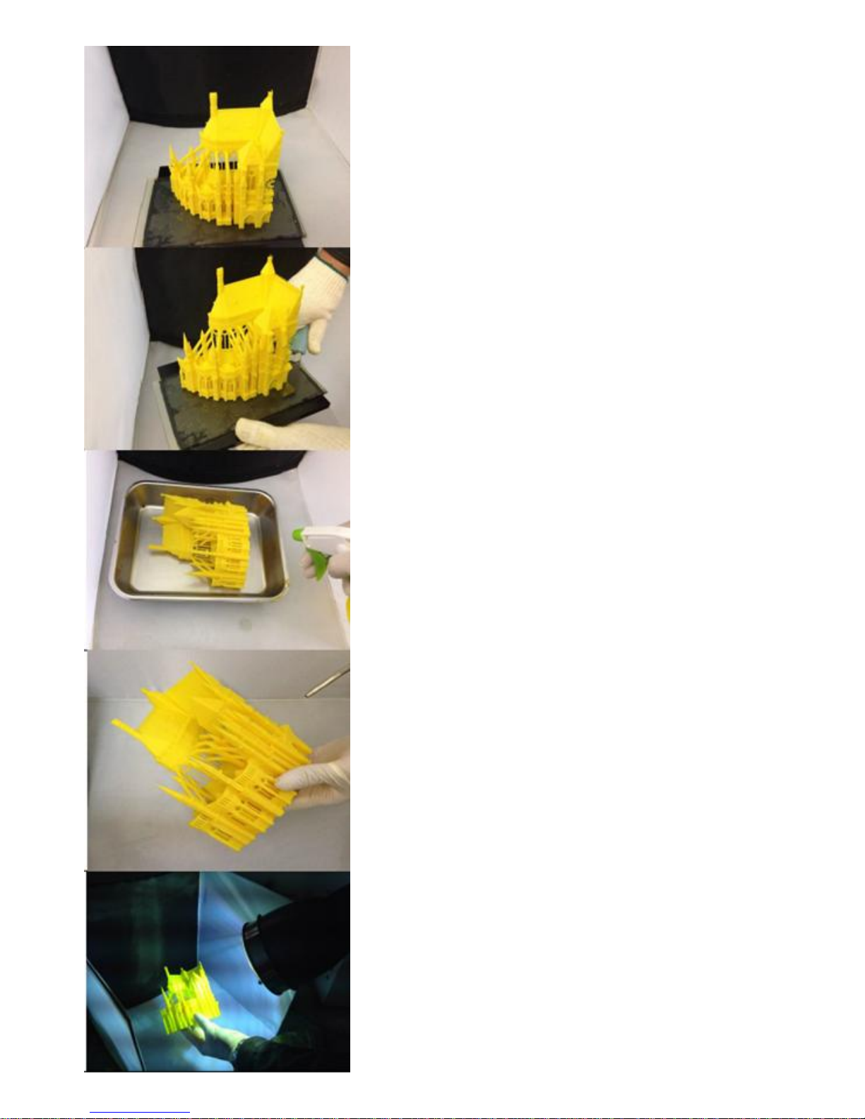
37
Take the mold out and place it on the work
table.
Use the cutter blade to remove the mold from
the build plate.
Remove remaining resin cleanly using alcohol.
Use a toothbrush with thin hairs to clean gaps
between.
Since the mold can be deformed by alcohol,
use the air compressor to clean it.
Dry the cleaned mold using the UV hardener.
Since light of the UV hardener is extremely
intense, make sure to wear protective
equipment before using it.
Page 41

38
Handling Resin Waste
1. Overview
Method of safely managing and lawfully handling chemical
substances and general wastes generated while using the device
according to environmental safety regulations
2. Type and Definition of Waste
1) Wastewater from cleaning of output
Wastewater generated when cleaning liquid resin on output
2) Output waste
Solid waste generated from printing of output
3) Hazardous waste (liquid)
Waste resin liquid remaining after printing of output
3. Waste Handling Procedure
1) Wastewater from cleaning of output
It can be drained if there is a treatment system in the building. It
must be entrusted for treatment by a waste treatment company if the
building does not have a treatment system.
2) Output waste
Output waste and general wastes listed below are handled as
general wastes instead of entrusting to a company.
3) Hazardous waste (liquid)
It is entrusted to a waste treatment company in a way that general
wastes are not mixed with hazardous waste (liquid).
- Items below are handled as general wastes.
└ Household chemicals like soap and detergent
└ Solid wastes after printing
└ Toilet paper and paper without chemicals
 Loading...