

Cargo Floor CF500 SLC Assembly Instructions Manual

Assembly instructions CF500 SLC Bulkmover
www.cargofloor.com Page 1
Version 01 / 12-12-2018
CARGO FLOOR
®
ASSEMBLY INSTRUCTIONS
CF500 SLC BULKMOVER
CF500 SLC 15/156,8
Cargo Floor B.V.
World's leading manufacturer and supplier of horizontal loading- and unloading transport conveyor
systems.
Assembly instructions CF500 SLC Bulkmover
www.cargofloor.com Page 2
Version 01 / 12-12-2018
INTRODUCTION
The assembly instructions outlined in this book will enable you to assemble the Cargo Floor system you
have purchased correctly. Every effort has been made, by means of diagrams and text, to ensure a clear
and simple installation. To ensure the durability and reliability of this revolutionary loading and unloading
system, it is important that you follow the assembly instructions as outlined in this book completely, and
use quality materials in accordance with the specifications. Please note that the guarantee is only valid if
the Cargo Floor system has been assembled in accordance with these assembly instructions. The latest
available version can always be found on our internet site: www.cargofloor.com
The measurements given in this instruction start with the metric system after which between brackets [0]
the imperial measurement is mentioned.
If the indications in this manual, as well as those stated in the user manual, are not followed
this could result in damages and/or injuries.
If your customer had any specific wishes we advise you to contact Cargo Floor B.V. This
especially when what is wished for differs from the so-called normal use.
(ADDITIONAL) INSTRUCTIONS
The following (additional) instructions are available:
Assembly CF3 LP-2 15-160
Assembly CF100 SLL
Assembly CF500 SLC
Assembly CF500 SLC Power Speed system
Assembly CF500 SLC Leak Resist Centre drive
Assembly CF500 SLC 15/156,8 XHDI / HD
Assembly CF800 system
Assembly Protected Seal 156,8 mm [6.17”]
Assembly Semi Leak Proof (SLP) system
The latest available version can always be found in the downloads section on our internet site:
www.cargofloor.com, downloads

Assembly instructions CF500 SLC Bulkmover
www.cargofloor.com Page 3
Version 01 / 12-12-2018
TABLE OF CONTENTS
Introduction .............................................................................................................................................. 2
(Additional) instructions ............................................................................................................................ 2
Table of contents ...................................................................................................................................... 3
Important recommendations and guidelines ............................................................................................. 4
Emergency stop ....................................................................................................................................... 7
Identification plate .................................................................................................................................... 8
Stickers .................................................................................................................................................... 9
Hoisting instructions ............................................................................................................................... 11
The chassis ............................................................................................................................................ 12
Mounting the plastic bearing strip at the back side ................................................................................. 13
Mounting the plastic bearing strip “Cargo Bulkmover” ............................................................................. 16
Positioning the system ............................................................................................................................ 17
Height adjustment and alignment of the Cargo Floor system .................................................................. 18
Securing the system ............................................................................................................................... 19
Bracing the side walls ............................................................................................................................. 21
Connecting the hydraulics ...................................................................................................................... 22
Choke ..................................................................................................................................................... 23
Mounting the plastic bearing “Cargo Twister WIDE 40/25” .................................................................... 24
Mounting the plastic bearing and anti lifting SPECIAL WIDE bearing 40/25 ........................................... 25
Cutting the floor profiles to size .............................................................................................................. 26
Round off the profiles ............................................................................................................................. 26
Driling the holes in the floor profiles ........................................................................................................ 28
MOUNTING THE SEAL .......................................................................................................................... 29
mounting the endcaps ............................................................................................................................ 30
Securing the floor profiles to the drive unit .............................................................................................. 30
Securing the stationary side profiles ....................................................................................................... 31
Mounting the control box and the electrics .............................................................................................. 33
The moving headboard ........................................................................................................................... 35
The moving headboard tarpaulin ............................................................................................................ 36
Adjustment of the threaded rod of the control valve ................................................................................ 37
Technical specifications .......................................................................................................................... 38
Maintenance instructions ........................................................................................................................ 39
Important instructions ............................................................................................................................. 40
Troubleshooting E-control....................................................................................................................... 41
Warranty conditions ................................................................................................................................ 43
Contact data ........................................................................................................................................... 45
TABLE OF CONTENTS OF THE ENCLOSED DRAWINGS
Attention: choose the system type that you are building in!!!
Subject ........................................................................................................................................ Drawing
System CF500 SLC H80-15-156,8, 12xM12 ................................................................................ S1-156,8
System CF500 SLC H100-15-156,8, 12xM12 .............................................................................. S2-156,8
System CF500 SLC H120-15-156,8, 12xM12 .............................................................................. S3-156,8
System CF500 SLC H140-15-156,8, 12xM12 .............................................................................. S4-156,8
Hydraulic drawing CF500 SLC A ........................................................................................................ H1-A
Hydraulic drawing CF500 SLC B ........................................................................................................ H1-B
Hydraulic drawing CF500 SLC E ........................................................................................................ H1-E
Proposal drawing hydraulic connections CF500 SLC ............................................................................ H2
Electric drawing E .................................................................................................................................. E1
Electric drawing B .................................................................................................................................. E2
Control valve ....................................................................................................................................... BV1
Control valve B .................................................................................................................................... BV2

Assembly instructions CF500 SLC Bulkmover
www.cargofloor.com Page 4
Version 01 / 12-12-2018
IMPORTANT RECOMMENDATIONS AND GUIDELINES
Before putting the Cargo Floor loading and unloading system into operation, follow the recommendations
provided below and check the specified checkpoints to avoid damage to the Cargo Floor system and the
vehicle.
Please review the important instructions before operating the Cargo Floor system and loading cargo into
the vehicle. Likewise, before loading cargo, check the operation of the various control switches/valves to
familiarise yourself with how the system works. We strongly recommend that you perform these checks
when picking up the vehicle from the dealer so that your skilled supplier can answer your questions and
provide you with any necessary advice or guidance you may require.
Important:
Always check that the selected loading or unloading direction is actually activated and occurring!!
If the system fails to start, turn off the Cargo Floor system and the hydraulic pump and follow the
recommendations and guidelines provided below. Do not repeatedly try to start the system as this
may result in damage to your Cargo Floor system and/or vehicle.
After use, turn off the Cargo Floor system and hydraulic pump. Set switches to the "0" position and
the lever in neutral.
In case of doubt or uncertainty about these recommendations and guidelines, always contact your dealer
or an official workshop.
The Cargo Floor system comes standard with an operating manual, but is this has not been supplied,
please contact your dealer or download it from the official Cargo Floor website: www.cargofloor.com,
download.
A) Always open the vehicle's doors before turning on the hydraulic pump. Note! Build-up of pressure
against the doors can open them with force. Also some of the cargo can fall out of the vehicle by
itself after opening the doors, therefore KEEP CLEAR AT ALL TIMES, product could fall on top of
you! Both could result in damages and/or injuries! It is always advisable to use the pneumatic door
lock, if provided.
B) 1. Check that the vehicle's (quick-detachable) couplings are properly connected to the P (Pressure
line) and the T (tank/return line). Also check that the couplings are fully tightened or slid completely
into each other.
IMPORTANT: the pressure and return line connectors may not be reversed or exchanged to
prevent dirt or water from entering the lines when connecting them!
2. Before connecting, check that the non-return valves can open easily (check: the non-return
valves should open easily when pressed with the finger, if not, potential pressure build-up in the
hydraulic lines may be preventing the system from starting).
NOTE: Incorrectly connected or unopened hydraulic couplings will cause serious damage to the
Cargo Floor system and the vehicle.
C) The vehicle (pump) must be fitted with a pressure relief valve that is set at the maximum pressure
according to the system, see the technical specs. If fitted, check that the dual-function lever
(function: tipper/Cargo Floor) is in the Cargo Floor position. Pressure may not exceed the
maximum adjusted and allowable operating pressure of the Cargo Floor system. An incorrectly
adjusted pressure relief valve can cause damage to the Cargo Floor system and the vehicle.
D) During operation, the (hand)brake of the vehicle must always be applied. You must, however,
move the vehicle forward on time to unload it quickly in order to prevent unnecessary strain and
wear to the floor and the vehicle.
E) Use of a wireless remote control is permitted only if it is fully tested before the start of each loading
or unloading operation. Always check if the function you have selected is actually activated and
taking place. If, for example, you have accidentally pressed the load function when you actually
meant to press the unload function, irreversible damage may occur to the Cargo Floor system and
the vehicle.
F) During operation of the Cargo Floor system, all existing STOP and control knobs/levers must be
freely accessible.

Assembly instructions CF500 SLC Bulkmover
www.cargofloor.com Page 5
Version 01 / 12-12-2018
G) The pressure filter element needs to be replaced at least once a year. If the couplings between the
vehicle and the Cargo Floor system are regularly removed, it is advisable to check the pressure
filter for dirt build-up and replace the pressure filter element more often, if necessary. If provided,
also check the return filter (not supplied with the Cargo Floor). Failure to replace a filter element on
time may cause damage to or malfunctions in the Cargo Floor system and the vehicle.
H) Moving parts must be shielded. Always maintain at least 10 meter [30’] distance from the Cargo
Floor system when it is in operation.
I) In the event of malfunctions/maintenance work, you may approach the Cargo Floor system only if
all equipment, including the hydraulic pump, have been shut off, and the Cargo Floor system and
the electro-hydraulic aggregate have been disconnected from the power supply and pump.
J) Regularly check and, if necessary, tighten any loose bolts that secure the aluminium floor profiles
to the Cargo Floor system. All such checks can simply be performed inside the vehicle itself by
qualified personnel. The Cargo Floor system must, however, be turned on in unloaded condition
and the person performing the check must place his finger half on the floor profile and half on the
bolt. There should be no appreciable movement/space between the floor profile and bolt. Failure
to check these bolts may lead to damage to the Cargo Floor system. During this check, a second
person must also be present to switch off the Cargo Floor system.
K) Check that the minimum required amount of oil is present 150 liter [40 US gallon]. Too little oil in
the hydraulic tank will cause damage to both the pump and the Cargo Floor system.
L) Do not allow the number of strokes to exceed the maximum allowable 16 power strokes per
minute. Only a CF500 SLC Power Speed Cargo Floor system may deliver up to 23 beats per
minute. A higher number of power strokes can cause damage to the Cargo Floor system and the
vehicle.
M) Hydraulic lines, couplings and hoses with very small diameters will cause damage.
N) If the Cargo Floor system fails to start or operates incorrectly, the Cargo Floor system and the
hydraulic pump must be shut down immediately. Subsequently, check all the checkpoints before
switching the pump and the Cargo Floor system back on. To prevent the oil from overheating,
regularly check the oil temperature by CAREFULLY and CAUTIOUSLY touching the line and or oil
tank. If either is too hot to the touch, stop touching them right away. WARNING: TOUCHING
OVERHEATED OIL AND COMPONENTS CAN CAUSE BURNS!
O) The cause of failure or malfunctioning of the Cargo Floor system may also be due to other
hydraulic components that may or may not be connected to the same hydraulic circuit of the Cargo
Floor system.
P) Jamming of the floor profiles caused by the transport of abnormal loads and or the freezing of the
floor or of the product to the floor may result in damage to the Cargo Floor system and the vehicle.
Recommendation: in the event of freezing, stop the system and try to find a hall (heated area) to
allow the product to thaw.
Q) Because the electrical power supply of the Cargo Floor system is often connected to the lighting
circuit of the vehicle, it is advisable to turn on the lighting throughout the operation of the system.
R) Maintenance and repairs to the Cargo Floor system may be only performed by qualified personnel.
Use only original Cargo Floor components to ensure maximum reliability and long service life.
S) Maximum cargo weight is subject to the limits set by law and applicable regulations. Even if the
system can transport heavier loads, the law determines the maximum limit. Excessively heavy
cargo can cause damage to the Cargo Floor system and the vehicle.
T) Check that the correct type and quality of hydraulic oil is used. The use of incorrect oil type may
cause damage to the Cargo Floor system and the pump.
U) Check the vehicle for correct voltage. Make sure there are no open electrical connections. A faulty
electrical system can cause damage to the Cargo Floor system and the vehicle.
V) Check that the bulkhead, if present, is functioning smoothly and properly. A properly functioning
bulkhead ensures that the product is unloaded in a clean and quick fashion. A malfunctioning
bulkhead may extend the unloading time and cause damage to the vehicle.
W) Use of the Cargo Floor system by unqualified personnel can cause damage to the Cargo Floor
system and the vehicle.
X) Excessively high oil temperatures will cause damage to the Cargo Floor system and other
hydraulic components, such as the pump.

Assembly instructions CF500 SLC Bulkmover
www.cargofloor.com Page 6
Version 01 / 12-12-2018
Y) It is at all times advisable to stop the Cargo Floor system when all the piston rods are retracted.
This is usually the case when the floor profiles are positioned towards the unloading end (vehicle
doors). Unretracted piston rods may cause damage to the Cargo Floor system.
Z) To prevent damage to the floor profiles, exercise caution and limit the dump height as much as
possible. The transport of unauthorised goods, such as aggressive, corrosive, hot, hard, sharp and
viscous materials may cause damage to the Cargo Floor system and the vehicle. Avoid loading
and unloading sharp objects. Loads that are softer than the hardness of the floor profiles will
extend the service life of your system; if in doubt, use a protective cloth or consult your dealer.
AA) Forklift trafficable. In principle, the floors are completely trafficable and can be driven over by
forklifts, but always consult your dealer for advice on the maximum loads allowed on your vehicle.
Overloading will cause damage to the Cargo Floor system and the vehicle.
BB) Always return emergency control(s) to their original non-activated position after use.
CC) During the operation of the system, test the temperature of the oil by touching the side of the tank.
If the oil is so hot that you cannot continue to touch the tank, switch off the pump to allow the oil to
cool off and determine what is causing the overheating. Stop loading or unloading if the oil is too
hot, as this will irreversibly cause damage to the Cargo Floor system and the other hydraulic
components.
WARNING: TOUCHING OVERHEATED OIL AND COMPONENTS CAN CAUSE BURNS AND
INJURIES!
Option: your Cargo Floor system could be equipped with an oil temperature safety switch which will
switch off the system automatically when it starts to overheat.
DD) During loading and unloading operations, the load should be spread to give an even weight
distribution over the floor area, otherwise the load may stall. Tip: when transporting pallets, place
softwood boards of 300 x 18 x 2350 mm. [12” x 0.75” x 92.5”] to distribute the pressure more
evenly.
EE) The constant pressing of the load against the head board or the doors can lead to extra wear of the
complete system. Also the construction can be damaged. Please consult your supplier about the
optimizing possibilities or in order to prevent problems occurring.
FF) The user/operator/driver that is operating the Cargo Floor system is compelled to remain a safe
distance from the Cargo Floor system at all times, from the time of switching on the hydraulic pump
until turning it off. He should ensure that no dangerous situations can occur. When the process
malfunctions or if other people are present he should shut down the Cargo Floor system, or
hydraulic pump, immediately.
GG) No unauthorized alterations/modifications/changes/adjustments may be made to any part of the
Cargo Floor drive unit and system.

Assembly instructions CF500 SLC Bulkmover
www.cargofloor.com Page 7
Version 01 / 12-12-2018
WARRANTY
Warranty is subject to prior approval by Cargo Floor B.V.! To request warranty coverage, visit
www.cargofloor.com, service to fill out and submit the warranty application form provided there; do not
forget to include your Cargo Floor system number on the form.
EMERGENCY STOP
In the event of an EMERGENCY, operation of the Cargo Floor system can be halted as follows:
By pressing the red stop button on one of the control switches;
By turning all switches to position “0”;
By putting the handle of the control valve in the middle “0” position (only B and A control);
Turning off the PTO pump/engine;
Turning off the main switch of the power supply;
Turning off the motor of the electro-hydraulic aggregate.
Assembly instructions CF500 SLC Bulkmover
www.cargofloor.com Page 8
Version 01 / 12-12-2018
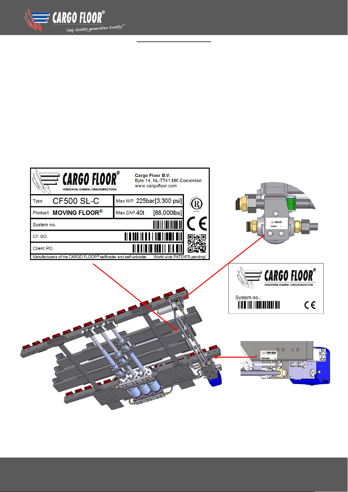
IDENTIFICATION PLATE
General extended identification plate
Next to the system number the Cargo Floor order number will be mentioned and a field with 9 digits has
been added in which we can, if required, put your identification or order number.
Numbers are automatically provided with a barcode; this makes it possible for you to scan the required
data.
Short small identification plate
An extra identification plate has been mounted near the rear bridge, above the threaded rod of the
control valve, so the system number can be read simply and swiftly at the outside of the trailer.
Paint and dirt protection
The identification plates are specially fitted with a double layer of transparent protective foil. The first
protective foil has a lip with remains visible when the Cargo Floor system has gotten painted or
exceptional dirty. This protective foil can simply be removed so the data is readable again and the
second protective foil remains intact so the data remains protected.
Assembly instructions CF500 SLC Bulkmover
www.cargofloor.com Page 9
Version 01 / 12-12-2018
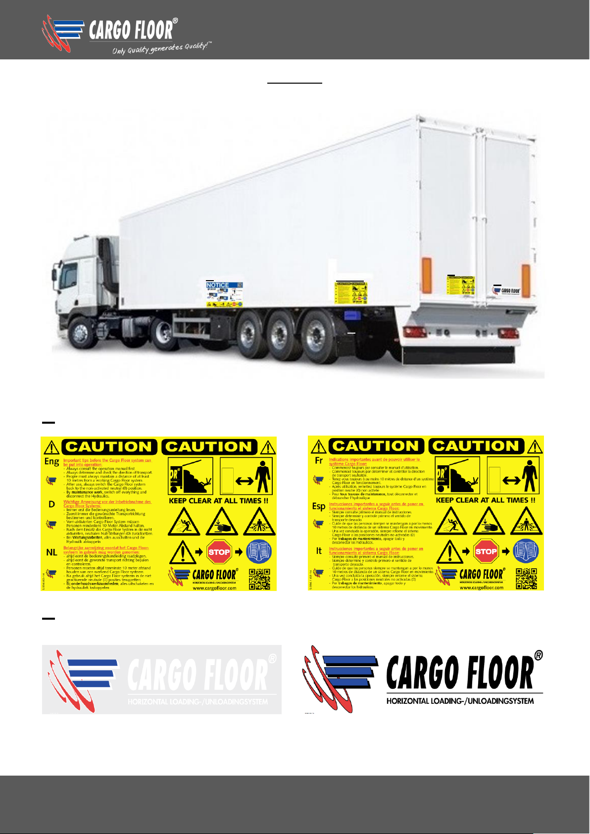
STICKERS
This WARNING STICKER/DECAL has been supplied with the drive unit in two fold. It should be attached
near the control box and on the rear door in such a way that it is easy to read.
STICKERS/DECALS ON THE TRAILER
A
…………………………………………………………………………………………………………………………
B
White/transparent Black/ transparent
or
………………………………………………………………………………………………………………………..
A + C
A B D
C
Assembly instructions CF500 SLC Bulkmover
www.cargofloor.com Page 10
Version 01 / 12-12-2018
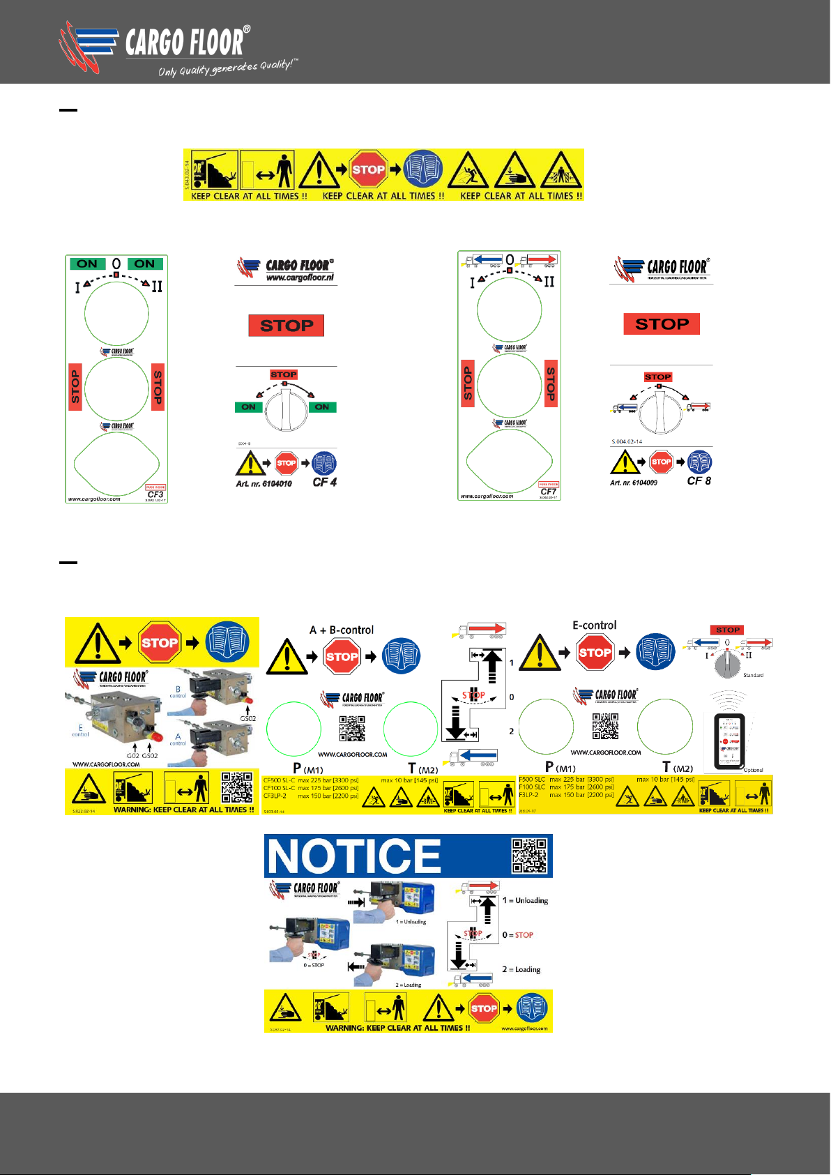
C
STICKERS/DECALS ON THE CONTROL BOX, ONLY WITH B- AND E-CONTROL
STICKERS/DECALS ON THE SWITCHES
Switch B-control Switch B-control Switch E-control Switch E-control
…………………………………………………………………………………………………………………………
D
STICKERS/DECALS ON THE SIDE OF THE TRAILER, NEAR THE DRIVE UNIT
Only A + B-control
Assembly instructions CF500 SLC Bulkmover
www.cargofloor.com Page 11
Version 01 / 12-12-2018
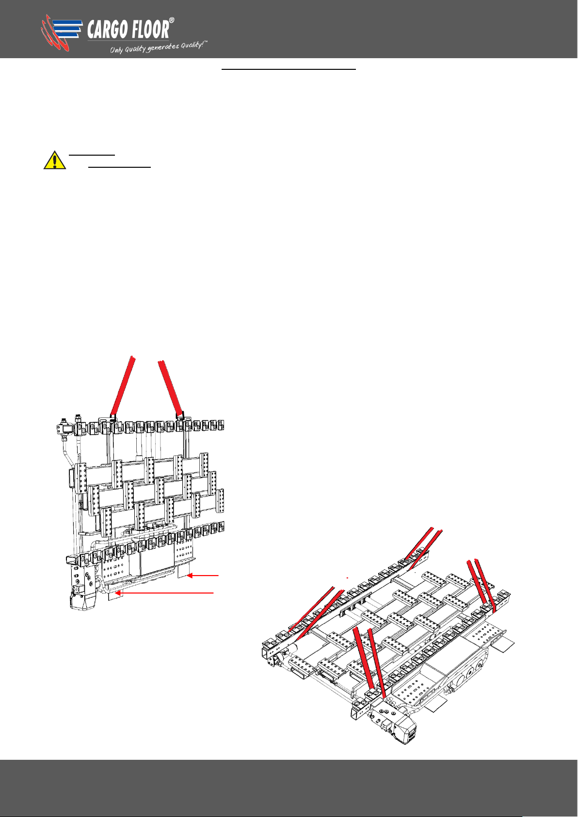
HOISTING INSTRUCTIONS
Attention!
If your system has been supplied with piston rod protection, this protection needs to remain put until the
end of the mounting process. It may only be removed just before you hand over the trailer to your
customer.
Warning!
It is not permitted to lift the Cargo Floor system by the cylinders, moving crossmembers, valves or
pipes.
You must use the hoisting points when lifting the Cargo Floor system (as shown in figure 2). You need to
pay particular attention that you use the right set of hoisting tools during lifting so that the bearings and
conduits do not get damaged.
The tilting plates mounted at the rear bridge are designed in such a way that they prevent damages
occurring to the cylinder bottoms, conduits and valve when tilting the system onto blocks or directly onto
the chassis.
The Cargo Floor system can be mounted directly on the chassis. Great care must be taken while placing
the Cargo Floor system to ensure that the system cannot slide away and cause danger and that there is
absolutely no damage caused to the system.
FIG. 2
Tilting plates
Assembly instructions CF500 SLC Bulkmover
www.cargofloor.com Page 12
Version 01 / 12-12-2018
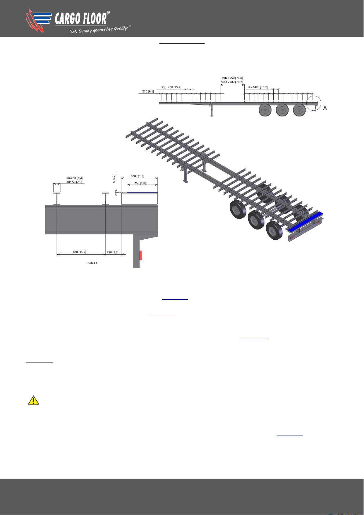
THE CHASSIS
It’s very important to ensure that, during the installation of the Cargo Floor system, the crossbeams are
flat on the chassis. The must be no difference in height between the crossbeams, as this would hinder
the installation of the system and adversely affect the operation and the lifetime of the Cargo Floor
system.
FIG.3
When using the plastic bearing on the rectangular tube 40x25x2 [1.6”x1”0.08”]
The top flange of the crossbeam may be a maximum of 60 mm [2.35”] wide and with a stabbed
crossbeam the top flange must protrude at least 7 mm [0.28”] above the chassis beam, if this is the case
use the Cargo Twister WIDE 40/25 (parts no. 4107031).
If the flange of the crossbeam is larger than 60 mm [2.35”] but smaller than 120 mm. [4.7”] then the
SPECIAL WIDE Bearing 40/25 (parts no. 4107034) can be used.
When using the plastic bearing strip
The plastic bearing strip “Cargo Bulkmover” 3/156,8-H32 Red (parts no. 4107036) can be mounted on
every width cross beam with a minimal measurement of 50 mm.
Remark: We strongly advise you to apply a stable crossbeam when using this plastic bearing
strip and also in the end area use an extra cross beam.
We refer you to figure 3 for the positions of the crossbeams for the various types of Cargo Floor
systems. Make sure that there is space free in the middle of the chassis for the Cargo Floor system.
Make sure that you choose the correct system type*!
CF500 SLC H 80 page S1-156,8 [6.2”] H100 page S2-156,8 [6.2”]
H120 page S3-156,8 [6.2”] H140 page S4-156,8 [6.2”]
A 300 mm [12”] wide plate must be made and mounted on the back of the chassis at the same height as
the crossbeam. A plastic wear strip of 2500x250x5 mm [98”x10”x 0.2”] (part number 4101007) must be
mounted on this plate. Pay attention to adjusting the height when mounting a ticker or thinner (than the
standard 5 mm) wear strip, the strip should always connect with the underside of the aluminium floor
profiles.

Assembly instructions CF500 SLC Bulkmover
www.cargofloor.com Page 13
Version 01 / 12-12-2018
MOUNTING THE PLASTIC BEARING STRIP AT THE BACK SIDE
In order to achieve an optimal sealing and prevent wear at the underside of the aluminium floor profiles
or the rear portal a plastic bearing strip (parts no. 4101007) needs to be mounted at the unloading side.
Alternatively a stainless steel wear strip (parts no. 4148012) can be mounted on the rear portal to protect
it from wear.
Mounting this strip is possible before mounting the floor profiles as well as after these have been
mounted.
Attention: when determining the position of the plastic wear strip pay attention to if the door is in or
outside the rear portal and mount the strip snug to the door.
The width of the wear strip should be at least 250 mm. [10”], length and thickness depends on your
construction. In order to be able to simply swap this plastic bearing strip it needs to be mounted in the
free part of the working stroke of the system. Determine, or have the system go to the front position,
cylinders in the fully out position. Fasten the plastic bearing strip with 6.4x16.8 countersunk rivets with a
range of 4 to 12 mm [0.2 – 0.5”] (parts no. 5017003), so these do not come into contact with the moving
floor. The stainless steel strip already has a hole pattern.
Put a small layer of sealant on the rear portal before mounting the plastic bearing strip, this prevents
corrosion and dirt accumulating between the plastic bearing strip and rear portal.
After finishing the mounting of the plastic bearing strip, seal all the edges fully with sealant.
Determine or place the system in the front position
190
[3.6]
20
[0.8]
Plastic bearing strip 4101007
Example hole pattern

Assembly instructions CF500 SLC Bulkmover
www.cargofloor.com Page 14
Version 01 / 12-12-2018
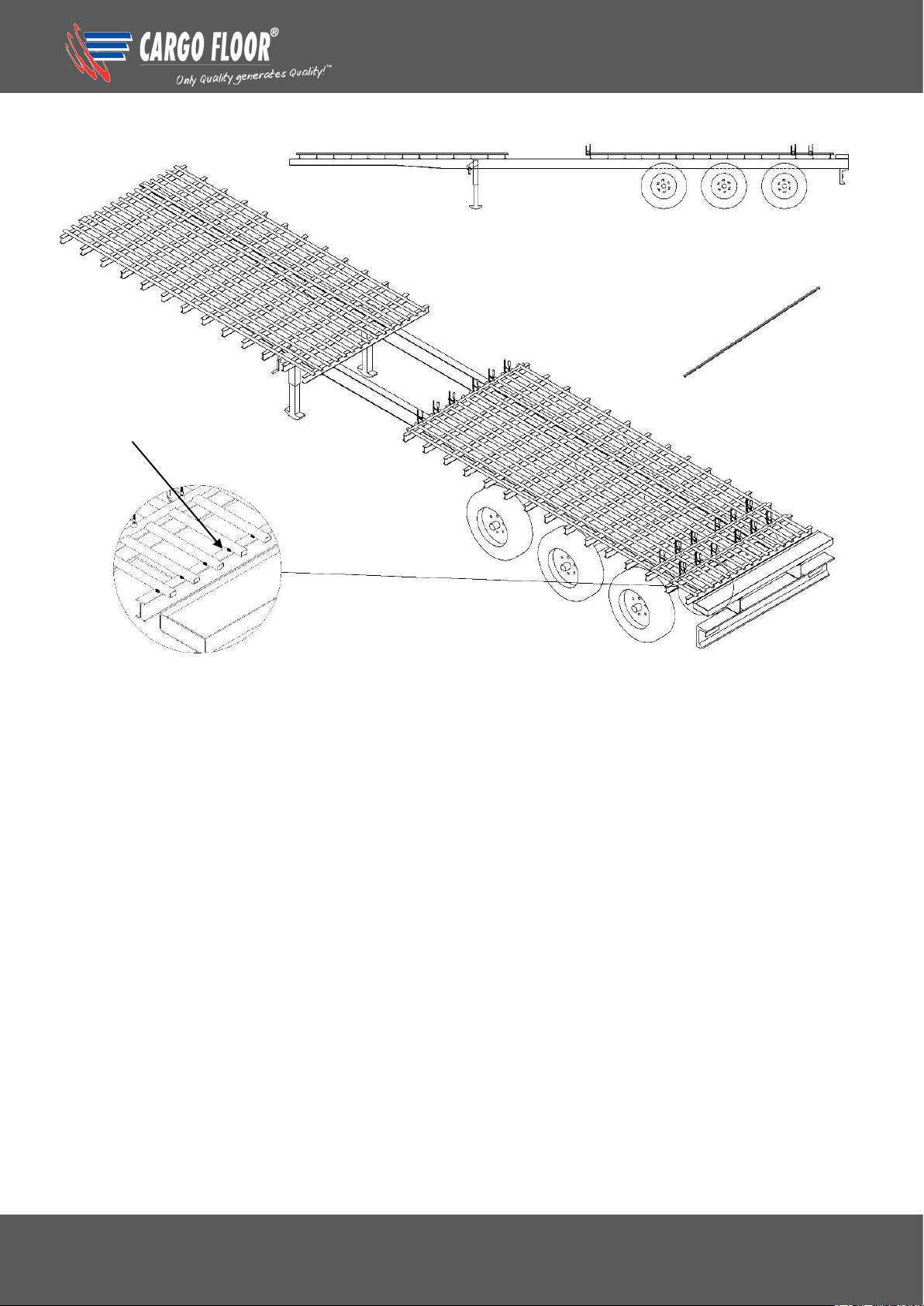
MOUNTING THE (40X25X2 [1.6”X1”X0.08”]) RECTANGULAR TUBES
A rectangular tube needs to be installed, over the full length and along the exact centre line of each of
the crossbeams (fig. 4 A). The rectangular tubes need to be securely welded on both sides to each
crossbeam with a weld of at least 20 mm. [0.39”] length and thickness of 5 mm. [0.20”] (as shown in
figure 4 B).
Pay attention to that the start and end positions of the tube protrude far enough (50 mm. [2”]) so the
plastic bearing (Cargo Twister WIDE 40/25, parts no. 4107031) can be mounted at that spot. (In fig. 4 A
these are the details A-C and B-D.) This tube is used as a reference for the mounting of the other tubes
with the help of the three welding jigs that have been supplied.
FIG. 4 A
After this, all other tubes need to be mounted in exactly the same manner as the middle tube. Use the
welding jigs (3 pieces, parts no. 9112008) for the right positioning of these tubes. All rectangular should
be - oneside and in the same direction - pushed into the welding jig. The jig needs to be fastened
securely to the crossmember to no height differences can occur between the rectangular tubes. See fig.
4 B for positioning and use of the welding jigs.
Assembly instructions CF500 SLC Bulkmover
www.cargofloor.com Page 15
Version 01 / 12-12-2018
FIG. 4 B
A= 5
L= min. 20 mm [0.39”]
both sides
Assembly instructions CF500 SLC Bulkmover
www.cargofloor.com Page 16
Version 01 / 12-12-2018
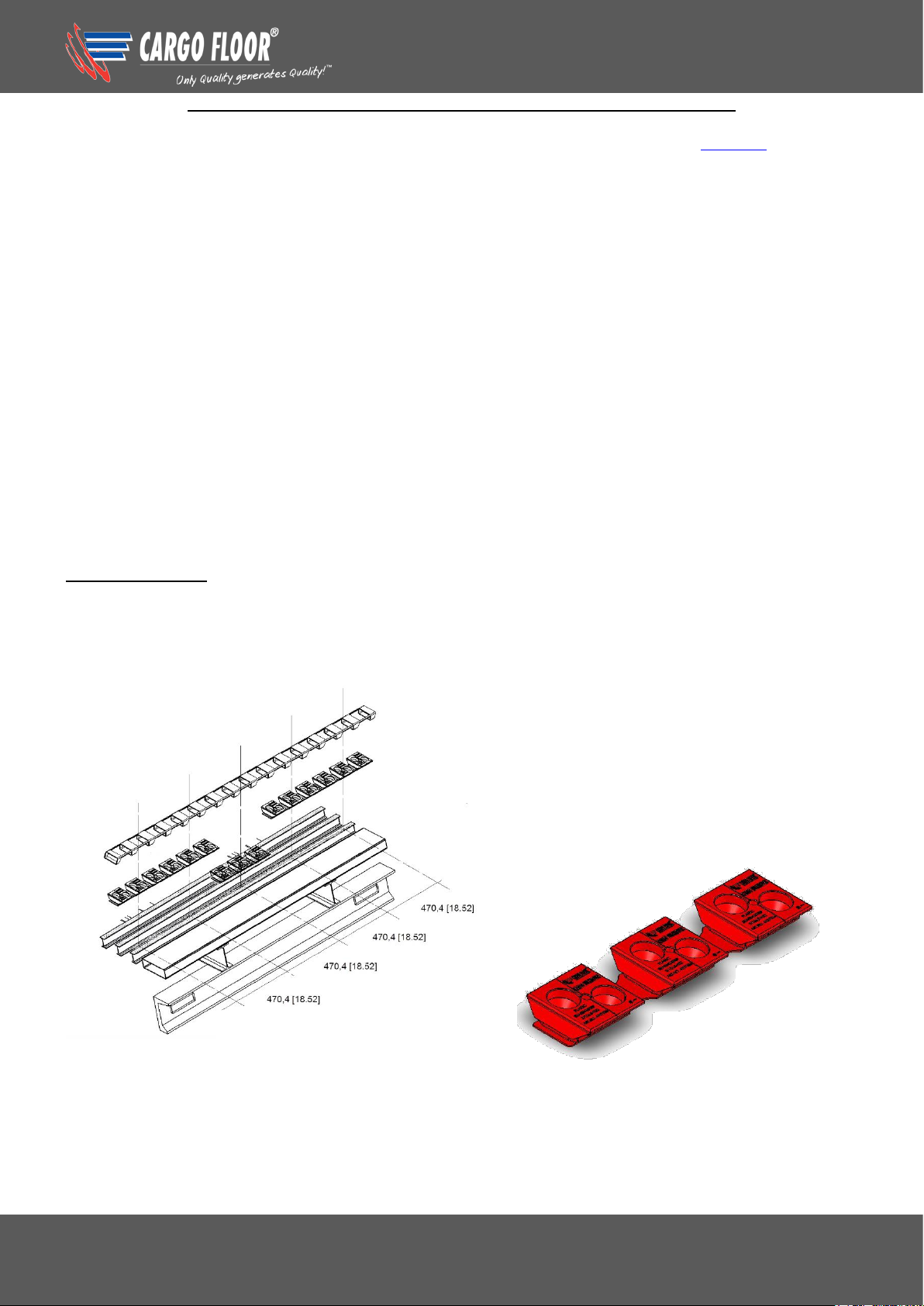
MOUNTING THE PLASTIC BEARING STRIP “CARGO BULKMOVER”
When using the plastic bearing strip “Cargo Bulkmover” 3/156,8-H32 Red (parts no. 4107036) one
should check beforehand if the height corresponds with the height of the drive system. Every strip has,
on the bottom side, positioningslips, so every strip can be mounted easily and parallel to the cross
member. The strip furthermore has been constructed in such a way that the floor profile can be clicked in
from the top.
5 pieces of plastic bearing strip are mounted next to each other on a cross member. The centre line of
the block in the middle of the strip needs to be mounted in the centre line of the chassis. The centre lines
of the plastic strips are indicated on them.
When mounting the four outer strips one needs to measure anew from the centre line to the centre line
of the block in the middle of the strip, or use the positioning jig 15/156,8 "Bulkmover" (parts no.
9111206).
We advise to use a cross member with a top flange of at least 50 mm. Every plastic strip should be
fastened with the six available mounting points.
Note:
When using this plastic bearing strip we strongly advise you to use a stable cross member and to make
sure that the under frame is strong enough. For the alignment, we do advise to use our mounting jig,
parts no. 9111206.
Points of attention:
Determine the center line
Mount middle strip center line – center line
Use all mounting holes available
On the rear one can/may use an extra cross member
Assembly instructions CF500 SLC Bulkmover
www.cargofloor.com Page 17
Version 01 / 12-12-2018
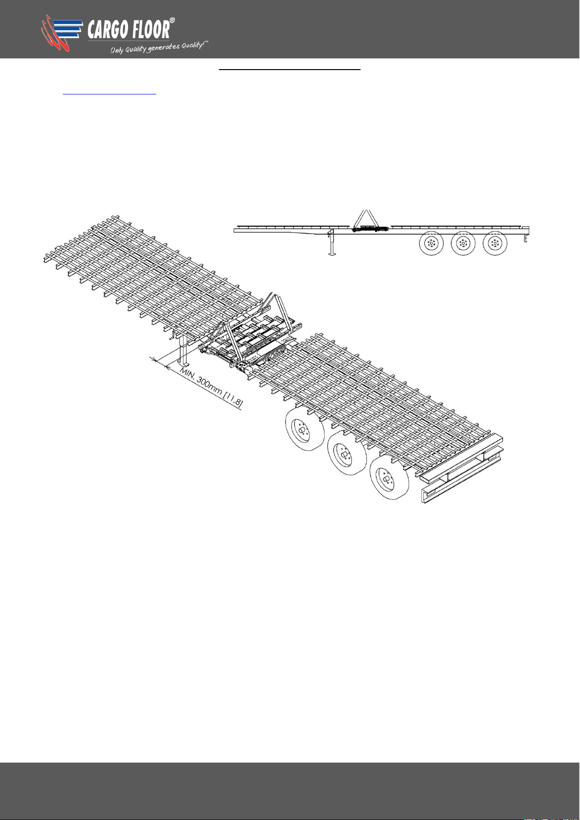
POSITIONING THE SYSTEM
The hoisting procedures need to be studied before placing the CF500 SLC BULKMOVER system. The
CF500 SLC BULKMOVER system can now be laid in the appropriate opening on the chassis / frame
(see figure 5), noting that the piston rods must always point in the head board direction.
FIG. 5
Assembly instructions CF500 SLC Bulkmover
www.cargofloor.com Page 18
Version 01 / 12-12-2018
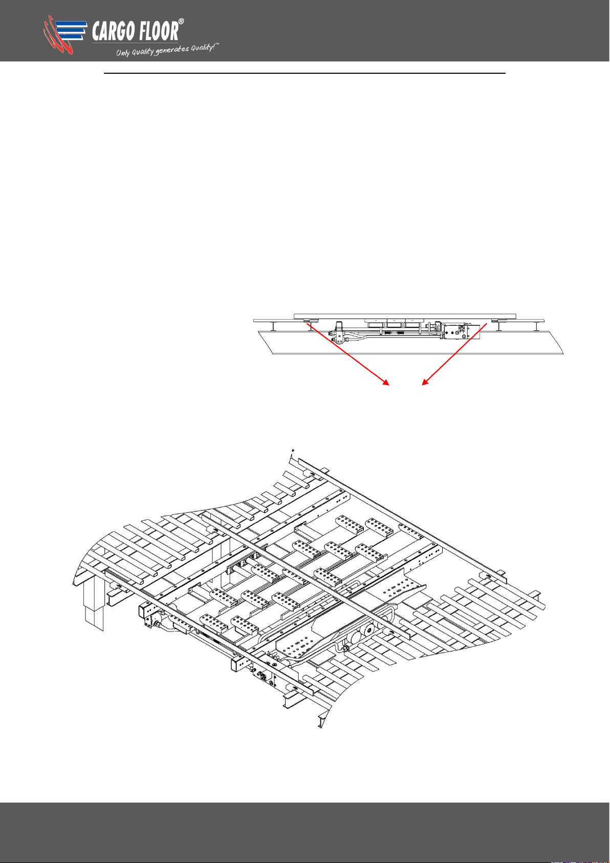
HEIGHT ADJUSTMENT AND ALIGNMENT OF THE CARGO FLOOR SYSTEM
Height adjustment
The Cargo Floor system needs to be at the same height as the plastic bearing that are mounted on the
crossbeams. The top of the U- profile of the moving crossmember (U-fasteners for the floor profiles, see
figure 6) is the reference. Any extra spaces that have been created between the chassis / frame and the
underside of the Cargo Floor system should be filled.
Alignment
It is extremely important that the Cargo Floor system is exactly lined up with the plastic bearing. The
piston rod of the middle cylinder is used as reference for this. The centre line of the moving
crossmember finger (U-fastener for the floor profiles) must be exactly in line with the centre line of the
plastic bearing mounted on the crossbeams.
It is advisable to clamp the Cargo Floor system securely once it is correctly positioned.
FIG. 6
Bearing
 Loading...