

Page 1

Vedpak 141GB_Version 2_22.10.09
160793
GB
1
Automotive components since 1963
GB
160793
Multimedia Rear-View Mirror
USER MANUAL
Vedpak 141GB_Version 2_22.10.09
Page 2
2
Vedpak 141GB_Version 2_22.10.09
160793
GB
Safety instructions
1. Read the instructions carefully before installation, to
avoid damages caused by incorrect operation.
2. The installation must only be carried out by authorized
and skilled personnel and in keeping with local
safety regulations.
3. Only operate the system with 12V˜28V DC power supply.
4. Only use the mirror and control box in dry and dust free
location, away from heat.
5. Do not use the mirror for a purpose other than described.
6. Do not cover with other devices.
7. If liquid gets into the unit case, disconnect the unit from
power supply and have it checked by your
dealer before re-using to avoid the danger of electric
shock.
8. For cleaning and care, always follow the notes in
instructions.
9. If electronic back view function is necessary during
driving, make sure it is done safely. Any accident
due to operation of this equipment during driving will be
the sole responsibility of the driver.
Standard Product Configuration and
System Integration
Please familiarize yourself with all the components of this
product, making sure you have all the parts indicated below.
If any of the components are missing or damaged, please
contact the service center that will arrange for replacement
parts to be sent.
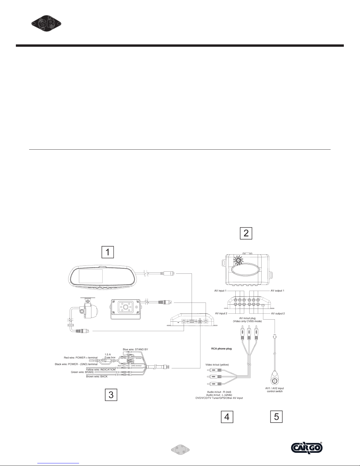
1. Electronic rear view mirror.
2. Control Box.
3. Power Line.
4. RCA AV Cable.
5. Wired control switch for selecting the signal from AV
input-1 of AV input-2.
6. 3 sets of belt for electronic mirror mounting on the
original interior mirror.
Page 3
Vedpak 141GB_Version 2_22.10.09
160793
GB
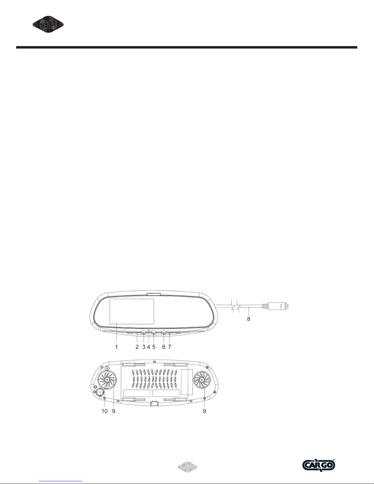
Electronic Rear View Mirror
The Multimedia Rear View Mirror is a 4.4” LCD color
monitor, which enables consumers to view objects behind
the vehicle. This product is the integration of a rear view
mirror with electronic display and an ordinary optical rear
view mirror. This makes it possible to not only use the mirror
for its usual function, but also to use the mirror to view
electronic pictures when powered.
Outlined below are the features of the product, the
electronic rear-view mirror, the control box and CCD camera
respectively:
1. 4.5” TFT LCD color display screen.
2. Slide control for adjusting screen brightness.
3. Auxiliary power switch for manually turning electronic
image of CCD1 or CCD2.
----OFF5CCD15CCD25OFF by pressing button CCD.
----CCD1 is especially for rearview.
4. Red/Green LED indicating power ON / OFF and function
switch.
5. Auxiliary power switch for manually turning electronic
image of AV1 or AV2.
----OFF5AV15AV25OFF by pressing button AV.
6. Auxiliary power switch for manually turning electronic
image of GPS.
----OFF5GPS5OFF by pressing button GPS.
7. Slide control for adjusting volume.
8. Male D-Type (15 pin) 3.5 mtr. system cable. This plug is
to connect to the control box outlet end.
9. Speakers.
10. GPS video input socket (composite video signal input).
Mini DIN 8P (Female) for GPS AV (composite video and
mono audio) signal input.
Page 4

4
Vedpak 141GB_Version 2_22.10.09
160793
GB
Control Box
1. Mirror or non mirror function switch for CCD
Camera 2 only.
2. CCD Camera 2 in.
3. Main system cable outlet.
4. Connect to the power line (DC 12/24 V).
5. CCD Camera 1 in.
6. Audio input 1 and Video input 1.
7. Audio input 2 and Video input 2.
8. Audio output 1 and Video output 1:
The image of 4.5” LCD can be output through AV
output 1. Therefore, DVR needed to connect to AV
output 1 if necessary.
9. Audio output 2 and Video output 2:
The signal from AV output 2 is for other monitors.
10. Switch:
AV signal from AV input 1 or 2 can output via AV
output 2 and be switched by wired control.
Page 5
Vedpak 141GB_Version 2_22.10.09
160793
GB
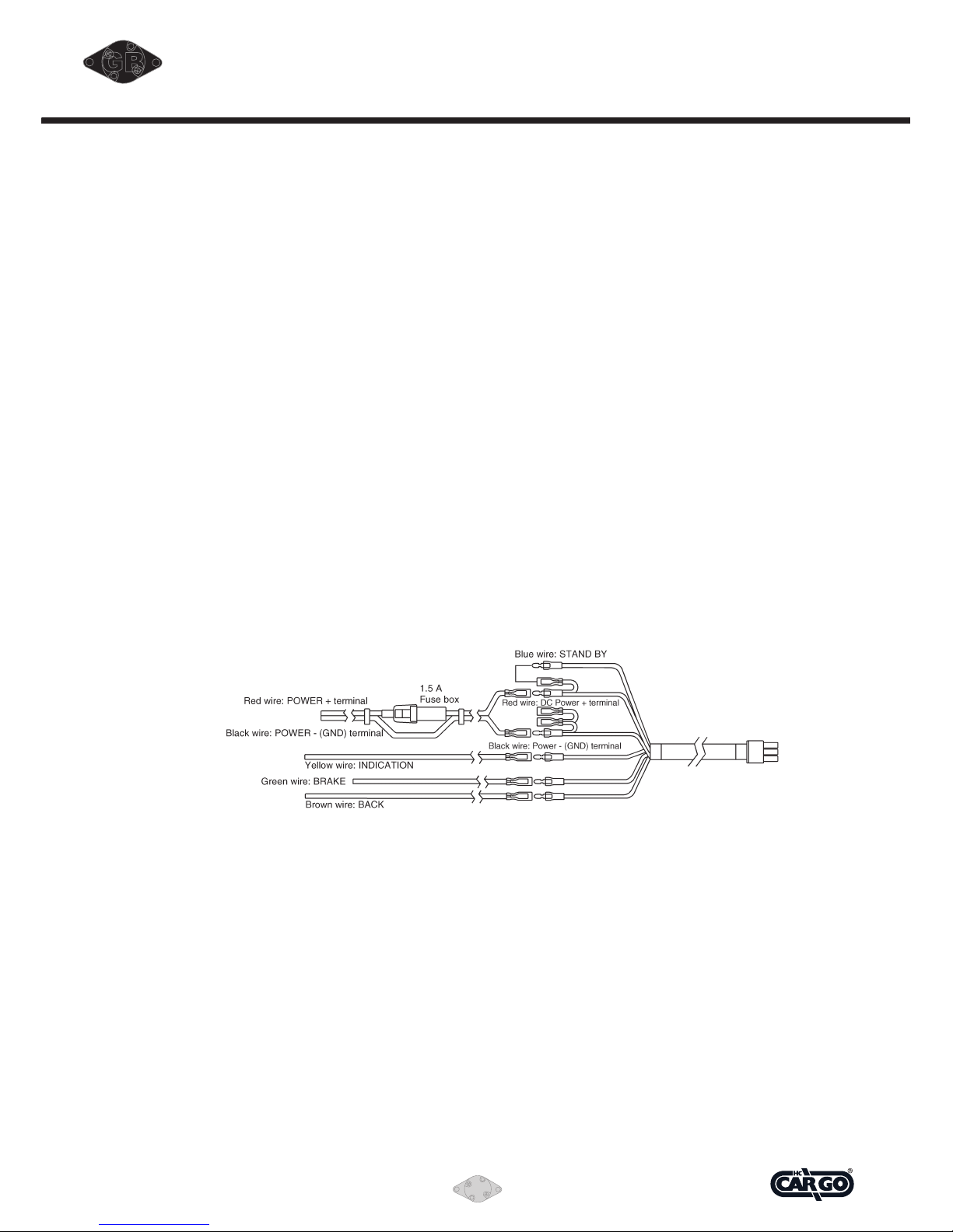
Power Supply Wire
Power supply wire: link to ignition switch.
1. Red wire: Link to the ignition switch (+).
2. Black wire: Link to the ignition switch (÷).
3. Yellow wire: Link to the indicator light if necessary.
Such wire connection is only for CCD2. If the yellow
wire will not connect to indicator light, the male connector
of the yellow wire needed to plug in the female
connector of black wire (÷).
4. Green wire: Link to the handbrake (÷) so that AV input
signal can be shown in the monitor while parking.
5. Brown wire: Link to the reversing light so that the mirror
monitor is automatically on while reversing.
6. Blue wire: The male connector of the blue wire needed
to plug in the female connector of red wire (+)
(indicated by arrow).
Page 6
6
Vedpak 141GB_Version 2_22.10.09
160793
GB
INSTALLATION PROCEDURES
1. Installing electronic
rear view mirror.
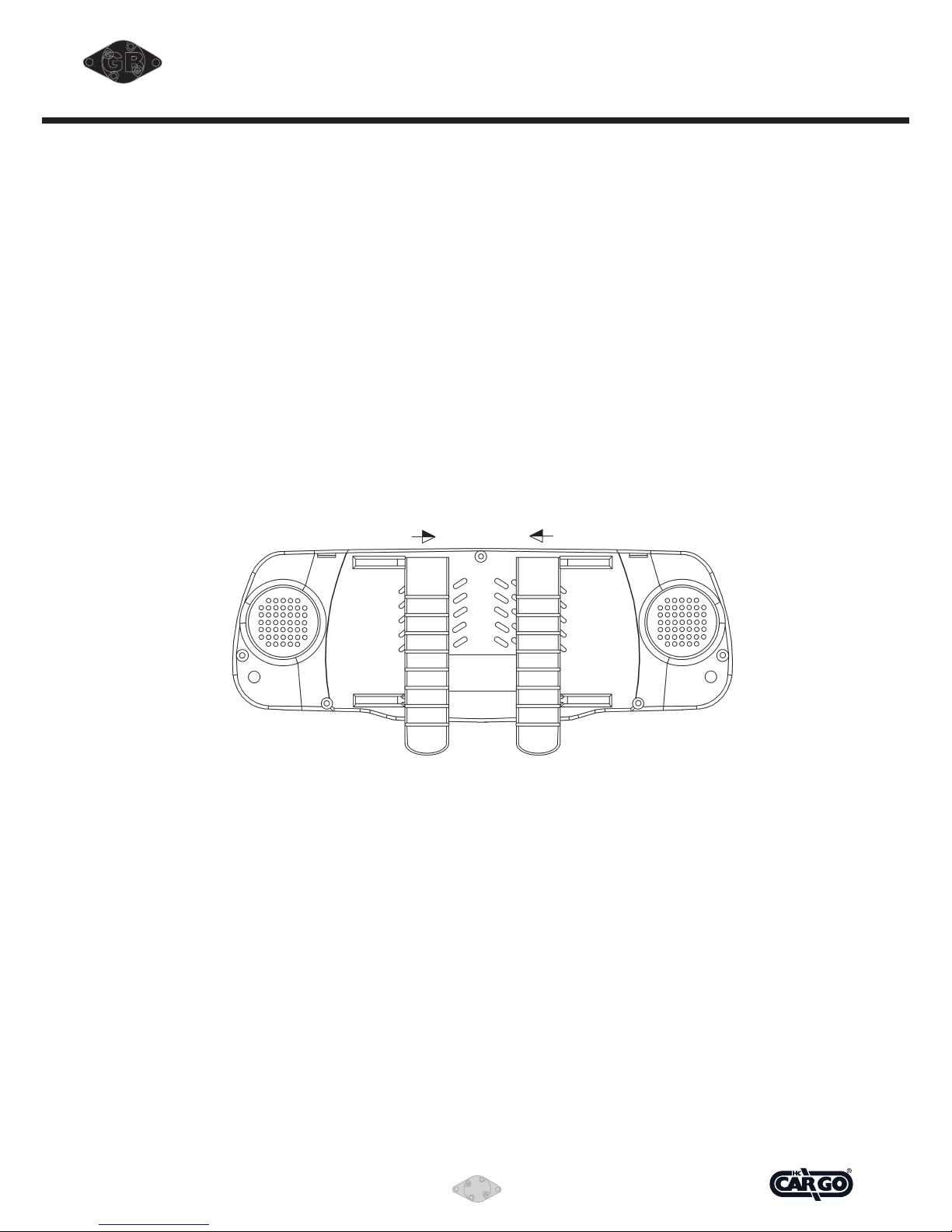
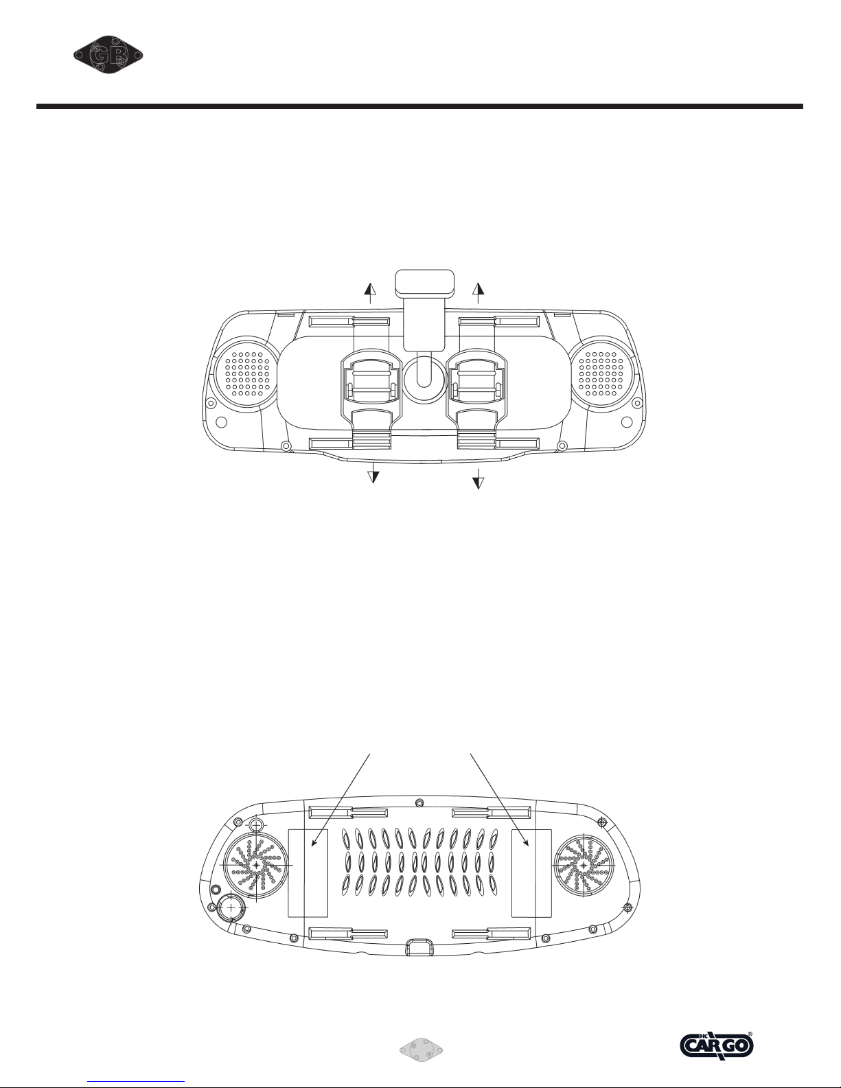
A. Insert the fastening strap into the raised groove on the
back cover of the mirror in the direction indicated in the
picture below, ensuring that the side of the strap with
the two notches feces outwards, and the indented side
inwards.
Attach the electronic rear view mirror on the original rear
view mirror. Tie the electronic rear view mirror
(already installed with strap and button trap) to the
original rear view mirror.
B. Insert the upper fastening strap into the hole with button
trap below without over-tightening the strap, to leave
room for the original rear view mirror.
Page 7
Vedpak 141GB_Version 2_22.10.09
160793
GB
C. Attaching onto the original rear view mirror in the
vehicle (as illustrated below). Put the side of the
electronic rear view mirror with connected trap to one
end of the original rear view mirror inside the
vehicle. Connect upper and lower straps on the other
side of the electronic rear view mirror in the method
described in step B, so that the electronic rear view
mirror is mounted on the original rear view mirror.
Adjust straps so that the two mirrors are completely
pressed against each other and neither can move
without the other.
D. Remove the protective film from the mirror; wipe the
surface with damp and soft non-erosive fabric.
E. Fix main cables behind the support of the original rear
view mirror, then guide them along the upper side
of the front windshield and finally conceal them under the
panel of the vehicle.
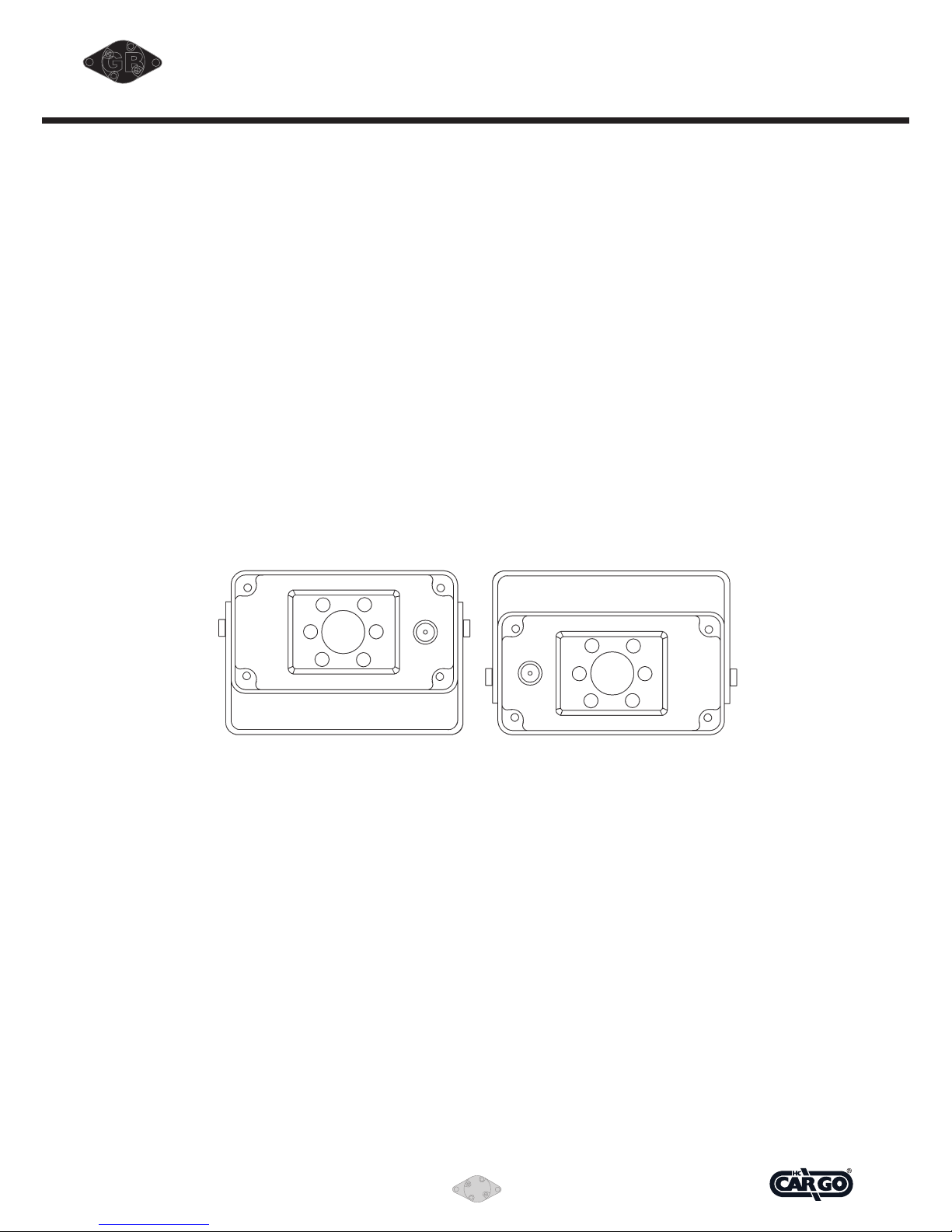
ATTENTION:
Stick the two adhesive foams backings on the back of
monitor. The two foams are for fixing the mirror monitor
firmly onto the existing one while fastening the straps. The
arrows indicate the two proper areas for sticking the two
foams. The two foams needed to stick simultaneously so as
to prevent the housing bent.
Page 8
8
Vedpak 141GB_Version 2_22.10.09
160793
GB
2. Installing control box.
A. Connect the Male D-Type (15 pin) system cable end plug
linked with the rear-view mirror to the corresponding
outlet on the ontrol box.
B. Place the control box in an appropriate place in the car.
If necessary, fix the contril box firmly by using the screws.
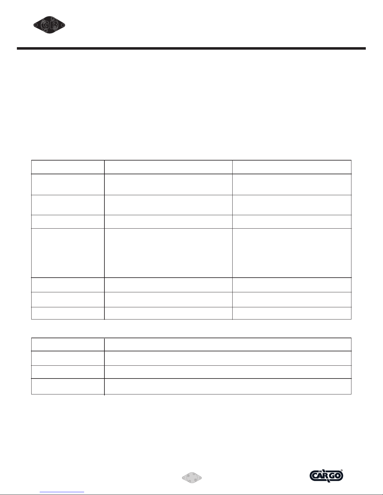
3. Installing CCD camera.
A. Mount the bracket firmly on an appropriate place on
the vehicle.
B. Reassemble the first camera and adjust the angle to an
ideal position. Fix the camera angle firmly by
fastening attached stainless steel socket screws.
C. Connect the 6 pins mini DIN male end plug onto the
extended cable then guide the cable along the
chassis then connect the male end of the extended cable
onto the outlet on the control box.
D. The camera should be only mounted as illustration
below.
CAUTIONS:
Because the rear blind zone is directly related with the
installation height of CCD, the CCD camera should be
installed on the proper location of the vehicle.
Page 9

Vedpak 141GB_Version 2_22.10.09
160793
GB
DESCRIPTION OF FUNCTIONS
Turn ON/OFF.
A. Turn the ignition switch to on, (it is preferably to start the
car and maintain in idle state to avoid excessive
consumption of battery energy).
B. Turn the ignition switch to off. The red LED on the
electronic rear view mirror should go off.
How to turn ON/OFF
the rear view function.
A. When the engine and the mirror monitor are both on, the
image is automatically generated when the
car starts reversing. When reversing is finished, the
mirror monitor will revert to the normal optical
rearview mirror.
B. When not reversing, the mirror monitor can be manually
turned on while parking or driving (the power
must be on) by switching on auxiliary power switch.
C. The mirror monitor can be used as normal optical
rearview mirror while turn off the built-in LCD.
How to play on-board
VCD/DVD/GPS/TV.
A. Make sure the green line is connected with handbrake
line in order to have video display only in brake mode.
B. Make sure the power for on-board
CD/VCD/DVD/GPS/TV system is connected.
C. Make sure the on-board CD/VCD/DVD/GPS/TV system
connected with control box by means of our standard AV
cable. When CD/VCD/DVD/GPS signals input through
the AV-IN port of the control box, the image can be
shown by pressing AV button on the electronic rear view
mirror.
Page 10
10
Vedpak 141GB_Version 2_22.10.09
160793
GB
MULTIMEDIA REAR-VIEW MIRROR SYSTEM SPECIFICATION
A. Control box
A. Total I/O terminal:
1. AV IN *2 (For DVD player or TV tuner.
2. AV Out *2 (For DVR * 1 and other monitors* 1).
3. CCD IN * 2.
4. Display OUT * 1 (for the driver).
B. Input signal:
Item
Voltage
Video
Audio (L&R)
CCD Camera
Back shifting signal
Direction signal
Remote
Description
Nominal: DC 12V/DC 24V.
Available range: DC 11.5˜28V.
PAL/NTSC composite video 1 Vp-p (140 IRE)
at 75 Ω input.
1.5 V (RMS) at 10 kΩ impedance.
CCD1: For rear view
CCD2: For baby (side) view
PAL/NTSC composite video input: 1Vp-p
(140 IRE), at 75 Ω impedance.
Rear microphone input: 200 mV (RMS), at 10
kΩ impedance. (CCD4 only).
DC 12V / 24V.
Direction signal pulse 12 Vp-p / 24 Vp-p.
TTL high level, for AV out select.
Connector
Wire with connector and turn on by
ignition switch.
RCA phone jack.
RCA phone jack.
6P mini DIN jack.
Wire
Wire
Wired control.
C. Output to display unit: D-SUB 15P (Female) connector with cable.
Item
Voltage / Current
Video
Audio (L&R)
Description
DC 11.0 V˜12.5 V (Regulated) / 0.7A (max.)
PAL/NTSC composite video 1 Vp-p (140 IRE) at 75 Ω impedance.
1.5 V (RMS) at 10 kΩ impedance.
D. Power consumption: 0.8 W (No load).
E. Dimension: 167 (W) x 43 (H) x 108 (D) mm.
F. Weight: 350 g. (approx.)
Page 11

Vedpak 141GB_Version 2_22.10.09
160793
GB
B. Electronic rear mirror.
A. Input connector:
D-SUB 15P (Male) with 3.6 mtr.cable, for connect to
control box.
Mini DIN 8P (Female) at the mirror back, for GPS AV
(composite video and mono audio) input.
B. Color TFT-LCD monitor:
1. Visible area: 4.5 inches (Diagonal).
2. Screen aspect ratio: 16:9.
3. Contrast: >300:1.
4. View angle: 90° (Horizontal), 40° (Vertical).
5. Brightness: 400 nit (typical).
6. Resolution: 960 pixels (Horizontal) x 234 pixels (Vertical).
7. Video system: PAL/NTSC compatible.
C. Audio power output:
1. Power output: < 0.5 W x 2 (8Ω speaker), < 10% THD.
2. Audio L/R channel balance: < 3 dB.
D. Power consumption: < 8 W.
E. Temperature:
Storege: -20°C ˜ +70°C.
Operation: +10°C ˜ +50°C.
F. Dimension: 285 (W) x 107 (H) x 30 (D) mm.
G. Weight: 650 g. (approx.)
Page 12
12
Vedpak 141GB_Version 2_22.10.09
160793
GB
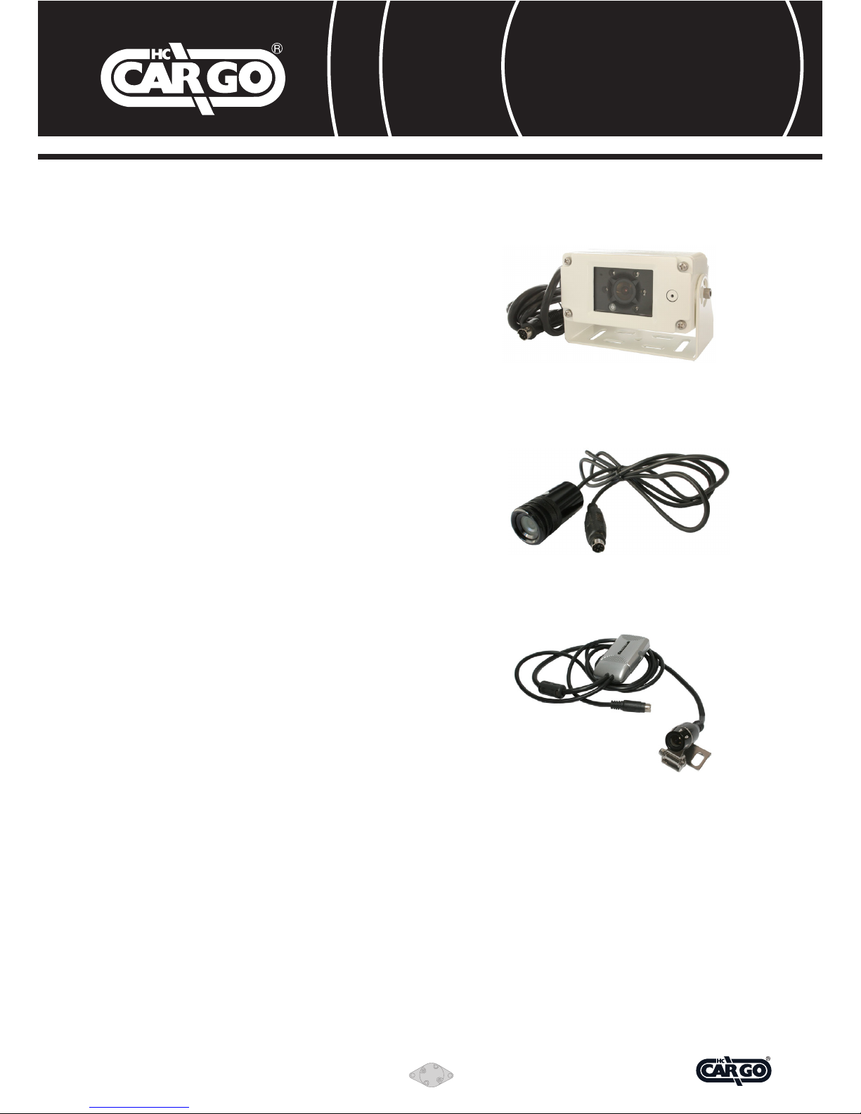
Extra EquipmEnt:
160609
Colour camera
• Casedinwaterproofaluminiumhousingfor
protection against foul weather and shock/vibration.
• Wideviewangle,150°diagonal.
• InfraredLED’sfornightvision.
• Built-inmicrophone.
• Connection:6pinMiniDIN.
• Protectiondegree:IP67.
160610
Colour camera (Bumper fit, Build-in)
• Aluminiumw/originalanodisednishandanti-fogglass.
• 30mm.(O.D.)x65mm.(L),200g
• Wideviewangle,130°diagonal.
• Sensitivity<1LUX.
• W/mirrorfunction(oncamera)
• Protectiondegree:IP68.
• Connection:6pinMiniDIN.
160790
Colour camera, mini
• 170° diagonal wide view angle.
• W/ mirror function.
• Sensivity>1.2LUX.
• Protection degree IP67.
• 21 x 40 mm.
Trailer kit.
Cargo 160663
3.5 mtr. coiled cable ext. length.
Extension cable:
Cargo 160672 ....6 mtr.
Cargo 160613 ....10 mtr.
Cargo 160612 ....15 mtr.
Cargo 160611 ....20 mtr.
Automotive components since 1963
160793
 Loading...