

Page 1
Construction Manual
Museum Scale All Composite Jet Aircraft
MiG-15 bis “Fagot”
V
e
r
s
i
o
n
2
Page 2

contents
1. Nose gear installation & nose gear doors
2. Ataching the wing to the fuselage
3. Installing the ailerons and servos
4.Installing flaps and servos
5. Bottom rudder and servo installation
6. Elevator and top rudder
7. Fuselage hatches
8. Speed brake doors
9. Engine installation
10. Main gear and doors
11. Ideas for Elecronic and hardware installation
12. Optional fuel tank installation
13. control throws / CG settings
14. Appendix
Page 3
Page 4

safety instructions and warnings
In the interests of your ownsafety and that of others,the model must only be operatedby experienced,
disciplinedmodellerswithsufficientspecialisedexpertise,anditmustbeservicedandmaintainedregularly
and competently. If you have no experience in building andoperating models of this type, it is vital that
you enlist the help and advice of an experiencedjet modeller if you are to avoid potentially catastrophic
errors; this applies in particular to the jet engine itself, which should only be run when an experienced
operatoris present.If you have a model flying groupor club in your area where training and supportare
available, westrongly recommendthat you jointhat group. Withthis modelany defector deficiency in its
constructionor operation canresult in seriouspersonal injury or even death.
CAUTION!
Beforeyouoperatethis modelaircraft, youmustdetermine the localby-lawsandregulationswhich apply
to you. In legal terms our modelsare classedas aircraft,and as sucharesubject tolegal regulationsand
restrictionswhichmustbeobserved.ContactyourRepregardingtheAMARegulationsforturbinepowered
aircraft.
WARNING!
It isyour responsibility toprotect othersfrom possibleinjury.Keepa safedistancefrom residential areas
in order to protect people, animals andbuildings: at least 1.5 km “as the crow flies”.
Keep well clear of high-tension overhead cables.Don’t fly the model in poor weather, especially when
thereis lowcloud coveror fog. Don’t fly themodel directlyinto thesun, asyoucouldeasily losevisual
contactwiththemodel. Toavoid collisions,alwayskeep well clearof full-size aircraft, whethermannedor
unmanned.It is your responsibility to landimmediately if a realaircraft approaches.
When operating a jet engine you must keep people and animals in a safe distance from it. This means:
In front of theturbine 4.5 m
To the side of the turbine 7.5 m
Behindthe turbine 4.5 m
WARNING!
Theoperator of the model must be in full possessionof his or her bodilyand mentalfaculties. Operating
amodel aircraft undertheinfluenceof alcohol or drugsisnot permissibleunderany circumstances.This
applies both to the operator and to his or her assistants.
WARNING!
Radio-controlled model aircraft may only be used for the purpose intended by the manufacturer. They
must never be used as machines for carrying people or goods, nor for any other purpose except as
model aircraft. Misuseof this model may result in seriouspersonal injury or even death.
WARNING!
Itis importantnot tomakeany modificationsof anykindtothe model.If youdeviate fromthe instructions,
perhapsby using different componentsor materials, or bymaking changes to the structural design,you
mayseriouslyaffecttheability of the modelaircraftto functioncorrectly.Pleaseresist the temptation, and
build the model exactly asdirected.
WARNING!
Before youfly themodel it is essential to checkthe Centre of Gravity and thecontrol surface travels, as
stated in these instructions. These settings are very important, and our recommended values must be
observed. Before you fly the model, carry out a careful check of all the working functions and all the
control surfaces.Checkthe rangeof the radiocontrol system with the transmitter aerial collapsed.If the
checkissatisfactory,repeatit with theenginerunning,with anassistantholdingthemodelsecurely.Read
theinstructionssuppliedwithyourradiocontrolsystem,andmakesurethatyouobservethemanufacturer’s
recommendations.
Page 5

LIABILITYEXCLUSION ANDDAMAGES
You have acquired a kit which can be assembled into a fully working RC model
whenfitted outwith suitableaccessories,as described in the building instructions
inthe kit.However, as manufacturers,weat Composite-ARFarenot ina positionto
influence the wayyou build and operate your model, and we have no control over
the methods you use to install, operate and maintain the radio control system
components.Forthis reasonweare obligedto denyall liabilityfor loss,damageor
costs which are incurred due to the incompetent or incorrect application and
operationof ourproducts,or which areconnected with such operationin anyway.
Unlessotherwise prescribed by binding law, theobligation of theComposite-ARF
company to pay compensation is excluded, regardless of the legal argument
employed. This applies to personal injury, death, damage to buildings, loss of
turnover and business, interruption of business or other direct and indirect
consequentdamages.Inall circumstancesour totalliability is limitedtotheamount
which you actually paid forthis model.
BY OPERATING THIS MODEL YOU ASSUME FULL RESPONSIBILITY FOR YOUR
ACTIONS.
It is important to understandthat Composite-ARF is unableto monitor whether you keep
tothe instructionscontainedin thisoperatingmanualregardingthe construction,operation
and maintenanceof the aircraft, nor whether you install anduse theradio control system
correctly. For this reason we at Composite-ARF are unable to guarantee or provide a
contractualagreementwith anyindividual orcompanythat themodel you have madewill
function correctly and safely. You, as operator of the model, must rely upon your own
expertise and judgement in acquiring andoperating this model.
SUPPLEMENTARYSAFETYNOTES
Pre-flightchecking
Before every session check that all the model’s working systems function correctly, and
be sure to carry out a range check. This is the procedure: switch on the transmitter,
followed by the receiver. Leave the transmitter aerial collapsed and walk away from the
model. At the appropriate range check that all the control surfaces work perfectly when
you move the sticks.
Repeattheprocedurewiththeenginerunning,whilean assistantholdsthe model securely.
The first time you fly any new model aircraft we strongly recommend that you enlist the
help of an experienced modeller to help you check the model andoffer advice while you
are flying. He shouldbe capable of detecting potential weak points and errors.
Be certain to keep to the recommended CG position and control surface travels; if
adjustmentsare required, carry them out.
Don’t ignore our warnings or thoseprovided by other manufacturers.They refer
to things and processes which, if ignored, canresult in fatalinjury or permanent
damage.
Page 6

Servos
Ailerons: 2x DS 8411 or similar
Elevator: 2x Mini Servos with 50 in/oz or more (DS3328)
Flaps: 2x DS 8411 or similar
Rudder: 1x DS 8411 or similar
Nosegear steering: DS 8411 or similar
Engines
We recommend 20-25lb thrust engines.
JetCat P-80SX, P-100RX, or similar.
To use bigger engines is only recommended, when the
pilot really knows how to use the throttle stick. Of course, in
vertical manouvers it is good to have the power. But - in the
horizontal manouvers you have to have the throttle stick at 1/3rdAT MOST!!! It is not,
that you would destroy the plane with too high speeds, it is just that you will kill any
scale flight appearanceif you fly with to much thrust. The full scale just did not have it
either!!!
Recommended CARF accessories
1x # 370550 Mig-15 retract set
1x # 370600 Mig-15 Fuel Tank set
3x # 961100 Electronic 2-Way retract valve
1x # 961150 Electronic 1-Way brake valve
6x # 630530 Robart cylinder 3/8" no165
You should use at least a gyro on rudder, we recommend even to use a gyro on ailerons
to make the plane “fly on rails”-performance, even in heavy winds.
Recommendedequipment
Page 7
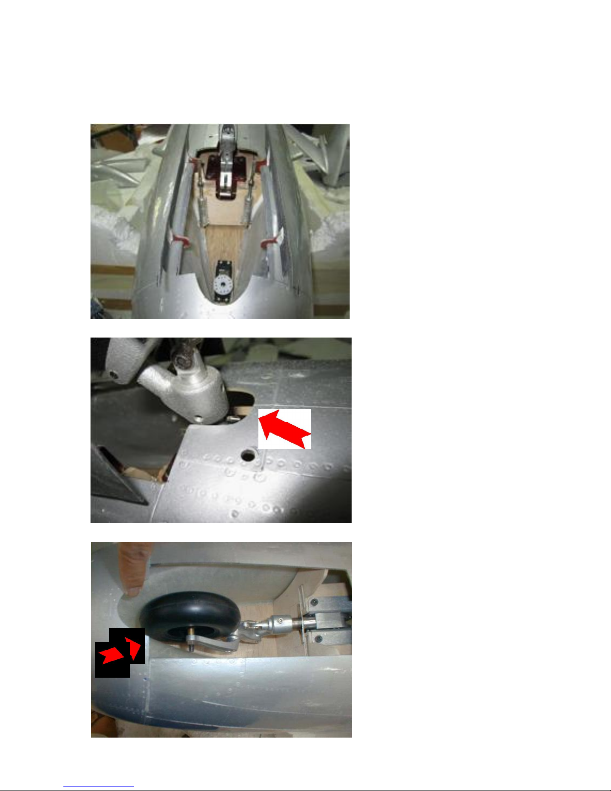
1. Nose gear installation and
nose geardoors
The front air intake duct and
the nose gear formers are
alreadypre-installed.
The nose gear unit is
preassembled already. Still
you might better take off the
strut, so that you can mount
and handle everythingeasier.
Fit the assembled nosegear
unit into the fuselage. Mark the
holes with a pencil.
Make the half round cutout
for the strut, as shown in the
folloing photos.
Drill the 5.5 mm holes and
insert the T-nuts from the top.
Check themovement of the
gear carefully, check the
angles and,especially, the
fit of the wheel inside the
air intake, whenretracted.
Wheel should touch slightly when retracted
Cut out
for strut
Page 8
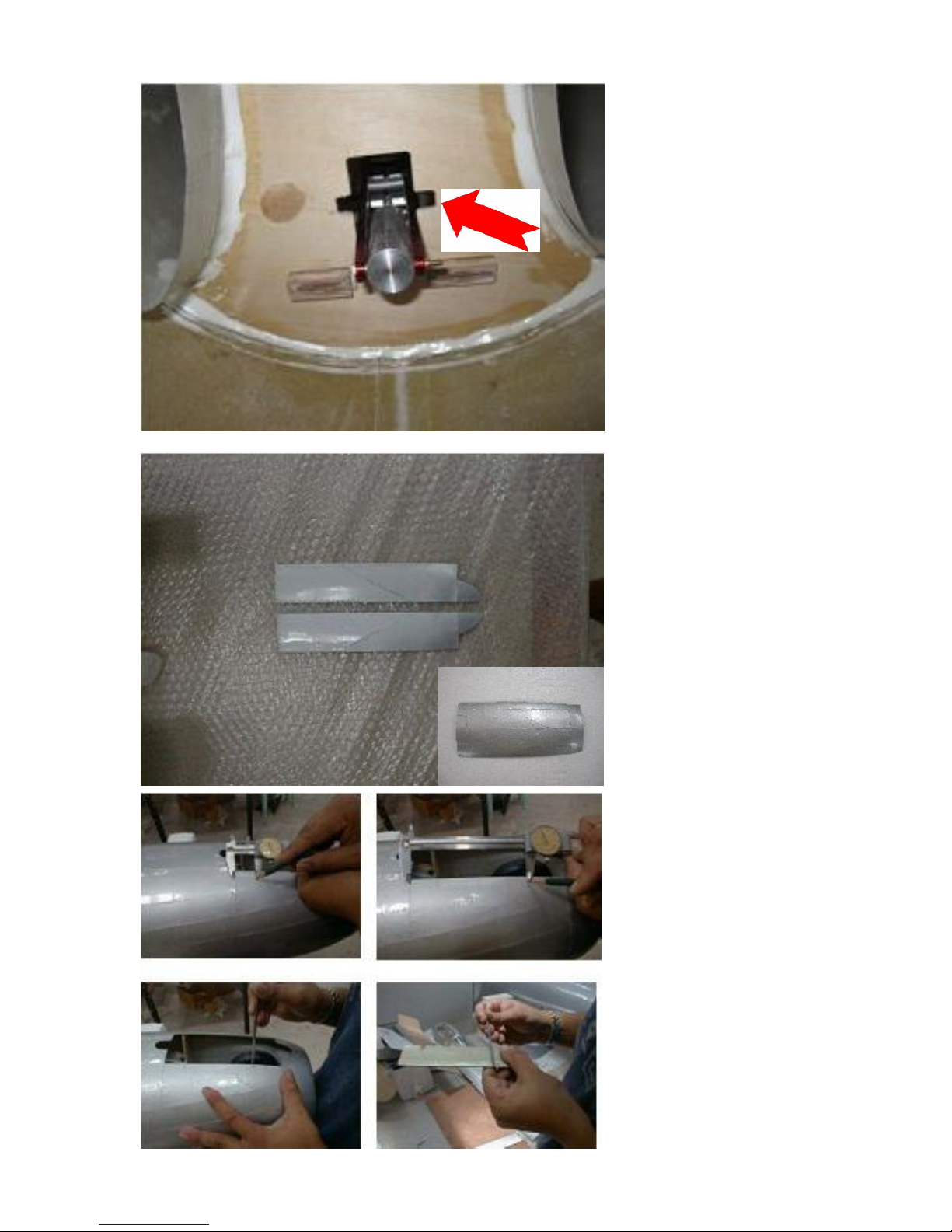
The cylinder of the retract unit
will stick into the fuselage as
shown.This gives easy
access to the air nippels later.
File a grove in the former to
easyly slide theair nippel
through.
Now cut the nose gear door
in half, and check the fit in
the gear door cutout.
Mark the position of the hinges
atboth gear doors and
fuselage.
Use a needle file to cut
the cutouts for the hinges,
and glue the hinges into the
fuselage. Make sure the
point of rotation is in the
center of the fuselages
cutout, approx 3 mm inside
of the border. See drawing
on the next page.
Page 9
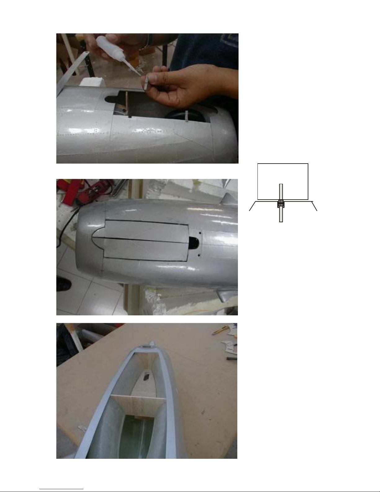
Be very careful with the CA
glue on the hinges, as said
before, it makes the plastic
weak.Only apply glue to
the hinge tips. The rest will
be filled with epoxy,after
the correct position is
confirmed.
Finally, whenthe glue has
set, move the gear doors and
see if they lock anywhere. If
so, sandcarefully in this
area, until they move
smoothly.
Glue in the radio
compartment floor and the
top part of the rear nose
gear formaer which will
complete your RCBox.
The front former can be
glued in now, but if you
decide to doa landing light,
leaveit out for now.
door
fuselage
point of
rotation
cut out!
Page 10
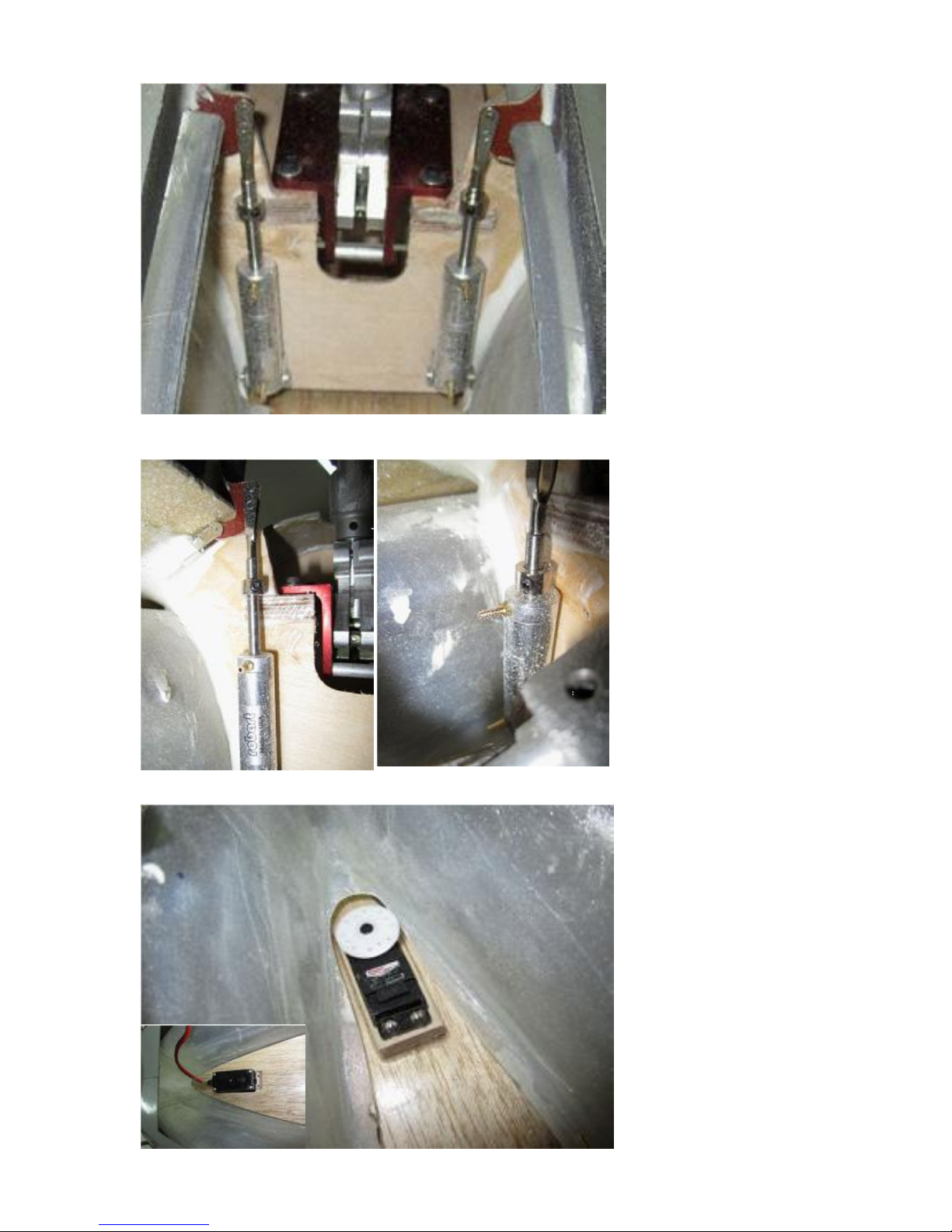
The gear door cypinders (we
recommend Robart #165)
are mounted to the front gear
former.Determine the
correct position of the
mounting holes, andpredrill
these holes with a small
drill bit.
to dertermine the correct
position, take the cylinder
and extendit to full. Fix the
control horn with a drop of
CAto the gear door.
After you set the angle of
the gear door to 90 deg.
whenopened, you got the
right point where to fix the
cylinder.
Mount the cylinders for
both gear doors with 2 sheet
metal screws each.
To adjust the correct closing
block position use a 4mm
collar on the piston rod.
Make sure not to tighten the
screw to much when testing
to find the correct position to
not damage the piston.
The nose gear steering servo
gets mounted in the front edge
corner of the nose gear
compartment. The cutout in
the former is already prepared.
Page 11
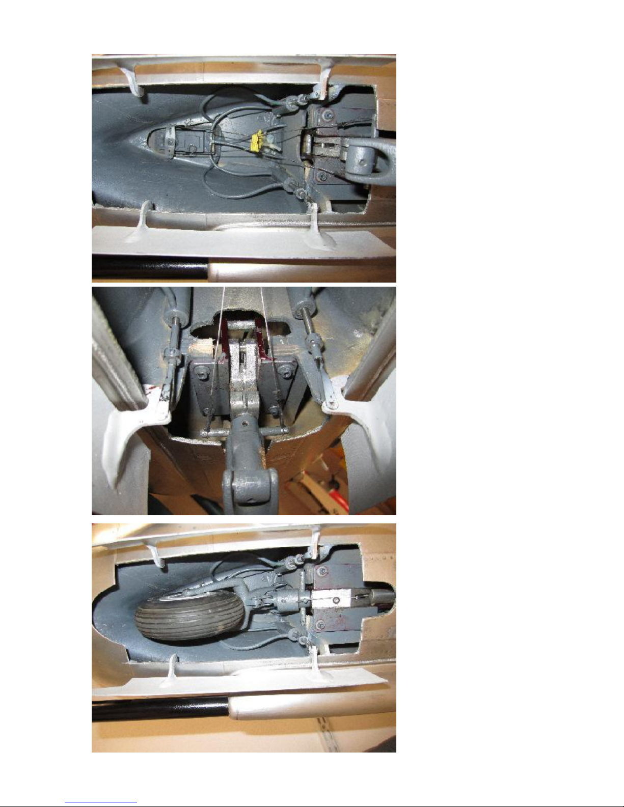
As the nosegearwill get it‘s
steering connection with two
pull-pull wires, the servo will
have to be mounted at an
angle, therfore a plywould
block of 9mm should be glued
under the rear mounting as
shownin the previous picture.
Page 12
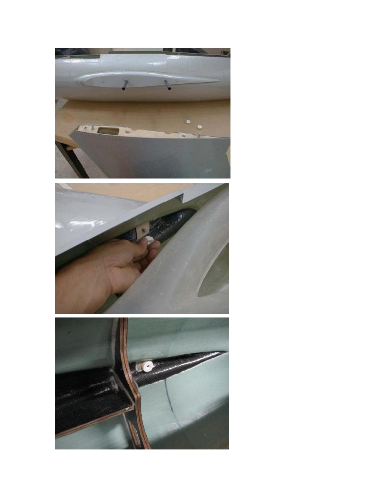
2.Ataching the wings to the fuselage
The wings are already
allinged and themounting is
already installed in the
factory.
Slide the carbon wing rods in
the funselage sleves and
then slide the wing on to
doublecheck propper fit of
the allingmet between
Fuselage and wing.
If necessary, sand on the
root rib sligtly to achief
perfect fit.
The wing rodsare slighly
different in length, thelonger
ones go in the front, the
shorter ones in the back.
Each wing gets secured to
the fuselage with two plastic
nuts as shown.
Page 13
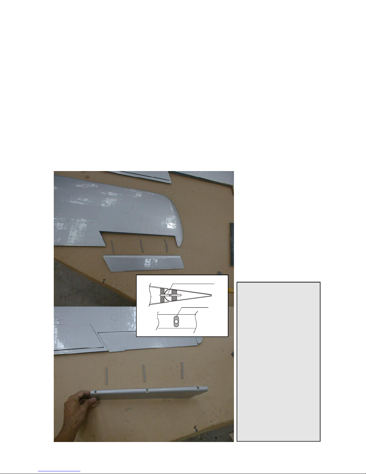
3. Installing ailerons and servos
Working Steps:
- install hinges and control horns to the ailerons
- install ailerons to the wings
- cut rear former of wings, install aileron servos and linkages.
You need:
- drill bit 5mm,round file, cutter, long phillips screw driver
- dremel milling tool, small pliers
- 5 minute epoxy (NO CA-Glue!!!)
- both wings and ailerons
- 6 Robart hinges, 2 small phenolic control horns, 2 servos
- servo installation hardware such as screws, extension
servo lead, 2 pieces M3 all thread, 4 clevis and 4 M3 nuts.
Installing the ailerons isan
easyjob, installing the servos
isa little bit more delicate....
Every aileron is mountedwith 3
Robart hinge pins. Drill 3 holes
in each aileron, as seen on the
bottom photo. Open the holes
in the fiberglassto an oval
shape, so that the hinges can
move free.
Gue in the hingesin one line
into the aileron. Use only 5
minute epoxy. Seethe drawing
for the principal of the working
hinge.
Make surethat you understand,that the point of rotation
is NOT at theleading edge of
the aileron, butin the center of
thecurvedleading circle! So
glue the hinges into the wood
only.
Tip for the Pro’s:
In case of the MiG-15’sswept
back wing the hinges should
not be mounted perpendicular
to the leadingedge of the
aileron. They should be
mounted parallel to the
aileron’s tip. Otherwise you will
have adifficult time to insert
the alileroninto the wing. If you
drill the holes and glue in the
hinges parallel to the aileron tip
this makes the assenbly much
easier. Of course the axis of
rotation of any hinge will not be
in one line then, but the
flexibility of the hinges and
thereallysmall travel of the
ailerons allow definitely todo it
this way.So make sure that
you drill all holes in the correct
angle, in aileronAND wing.
Robart Hinge
Page 14
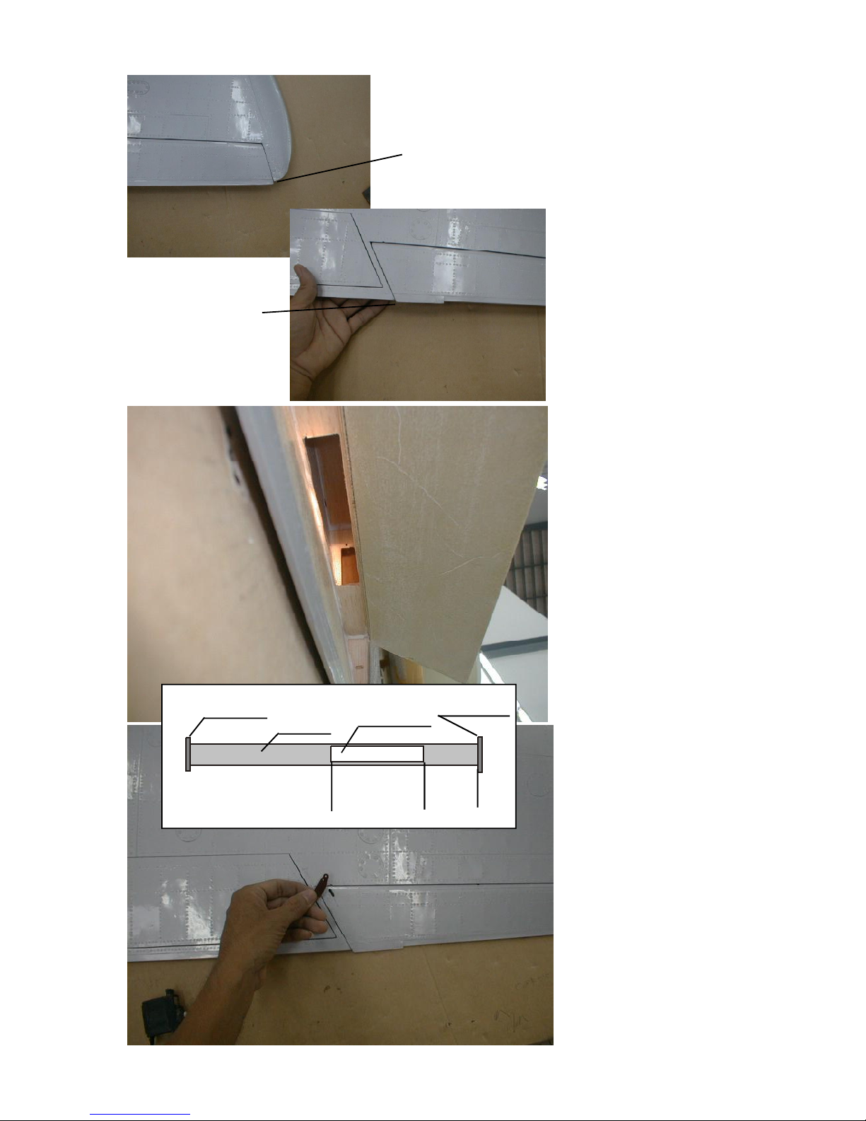
3 mm!
3 mm!
When youtrial fit the ailerons
to the wings please check on
the photosleft hand side. The
trailing edgeof theaileron
stepsback 3 mm from the
wingtip, and thetrailing edge
then continues in one line to
the trailing edgeof the wing.
The little trim tab onthe aileron
stepsout of this line again
about 3 mm.
Nowcut a rectangularhole into
the rear spar of each wing.
See the drawing belowfor the
exact dimensions.First, this
hole is to mount theaileron
servo, second,it allows to
bringin the flap linkageeasily.
Through this hole you can see
the servo mountfor theaileron
servo. It is designed for a
standard sizeservo. The servo
arm will have to be mounted to
thetop wing,slightly angled
backwards, so that the linkage
can go perpendicular from the
control horndirected to the
bottom surface of the wing.
The aileron control hornis
glued in from the bottom side,
and you have to cut a slot for
the linkageinto the bottom
wing skin, approx 25 mm (1”)
in front of the aileron control
horn.
But nowmount the control
horn first into bothailerons.
Mill a slot 2mm wideand
approx. 10mm long into the
botton side of the ailerons,
about 5-6 mm (1/4”) distance
from the aileron root. Make
sure NOT to cut the
root rib
aileron rib
cut out
flap spar
70 mm
2 3/4”
170 mm
6 3/4”
Page 15
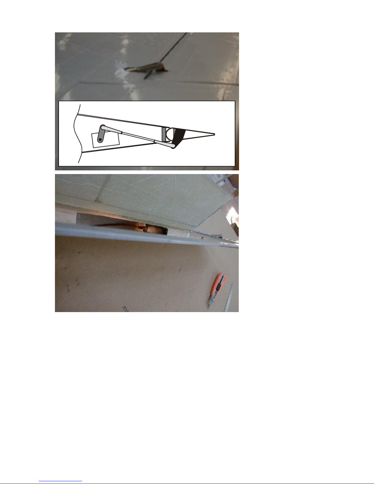
top sideof the ailerons. Then
glue in the controlhorn with 5
minute epoxy, sothat the hole
is approx. 6-8mm above the
aileron surface(1/4 - 3/8th”).
Make surethe horn is placed
exactly perpendicular tothe
axis of rotation.
Mounting the servo is a bit
tricky.The servo ismounted
reversedinto theinstalled
servo mount. Go ahead with
the following steps:
1. Trial fit the servo into the
mount. Mark the position of the
servo hornon the servo mount
rib. Then take the servo out
again.
2. Now cut a 10-15 mm hand
hole into the bottom wing skin,
exactly wherethe servo horn is
located. Youwill needthis
handhole to snap on the clevis
to the servo horn, when the
servo isfinally installed.this
hole can be covered with a
small pieceof lithoplate
aluminunlater.
3. Make the linkage with the suppliedM3 all thread.Adjust the length, sothat it can accept an M3 clevis on
both sides.
4. Slide the linkage through the slot in the bottom wingskin and snapit on to the control hornin the
aileron. Then check the lengthand direction of the linkage inside the wing, whetherit is matching up with
the mark you setto the servo mount rib. If not matching, adjust the length of the linkage, and if necessary,
the position of the slot. Usethe handhole to checkvisually the positionof the clevis.
5.After all is confirmed, finally mount the servo into the rib. Snapon the linkage tothe servo horn. (The
shorter the horn, the better it is, asthe control horn on the aileron is also very short)
6. Nowuse a long Phillipsscrewdriver (if not long enoughavailable, extend one with a pieceof brass- or
carbon tube, to mount the servo screws. You should use a drop of CA glue to fix the screwson the screw
driver, andthen insert them into the hole and tighten them carefully.The servo wirewill be longenough to
work on it through the hole in the rear sparin the flap area, we suggest to extend the wire permanently by
soldering, betterthan using a stock extension wire.
Page 16

5. Installing Flaps and Servos
Working Steps:
- cut flap servo hatch and mount servo
- install control horn and linkage
- install inner scale surface into the flap
You need:
- cutter (X-Acto Knife), sand paper
- CA Glue, Epoxy glue
- your wings
- 2 control horns large, 2 all thread M3, 4 clevises, 4 nuts M3,
- 2 servos, 2 milled servo mounts, balsa reinforcement parts
- 2 vacuum formed flap insides
Your MiG-15’sflaps are
already precut andhinged with
aspecial nylonelastic hinge.
The flaps are stiff already,but
will need some more rib and
sparstructure, especially to
mount the scaleinner surface
plates.This gives a
sophisticatedscale impression
on the plane on the ground,
whenthe flapsare down.
Start withcutting the servo
hatch. Locate the hatch in the
center of the flap, and see the
photos. Use panel lines as
cutting line. The wingskin cuts
easilywith acutter only.
Tip for the Pro’s:
The elastic hinge is a very
common way to hinge any
control surface, which has only
throw to oneside or the throw
to the other sideis at least not
too much. Contest pattern
planes,TOC-Planes, also
glidersand F5-E composite
wings havethis kind of hinging.
It is one of the most reliable
methods to hinge any control
surface.
Some important notes on the
“Elastic Hinge” in General:
The hinge is set up as a layer
of special“Perlon” cloth, which
does not soak up resin during
the laminating process. This
cloth is embedded in 2 layers
of fiberglass,so that the skin
around the hinge is hard. To
make the hinge flexible, both
glass layers must be cut or
broken, to achieve flexibility in
exact the hingepoint.
Done right, this kind of hinge
is unbreakable, and it will take
many thousands of deflections
with no wear and tear. You
shouldkeep CA-Glue away
from it, though.
Page 17
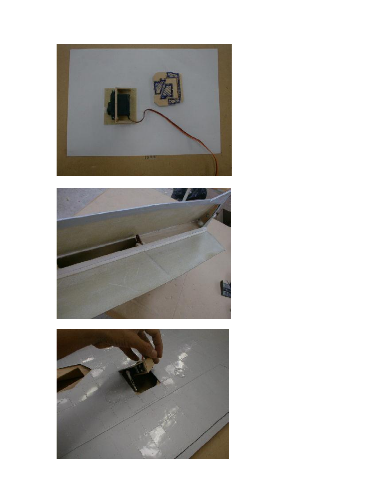
Take outthe hatch and assemble
the servo mount. The photo shows,
which parts to use. Make surethat
you glue the milled woodpartsvery
well to thehatch cover. UseCA
gluefirst, and thenfill excessively
with epoxy and milled fiber to geta
strong bond.To sand the surfaces
with a rough sandpaperis
mandatory and not further
mentioned inthis instruction book.
Then build aframe into the cutout
in the wing, so that you can mount
the hatch with 4 sheet metal
screws. It will be sufficient if you
usesmall plywood trianglesand
glue these 45 deg. into each corner
of the cutout, so that the hatch can
rest on the triangles. Make sure
that the screws have a goodgrip in
the wood,as there is a lot of load
espcially on the flap servo. Mount
the servo in the wood frame, using
the standard servo screws.
Now assemble the balsa stick and
the control horn inside theflap. You
must understand, thatthe control
horn must point 30 deg. forward, to
have asymmetrical travel through
the whole throw, especially to have
enoughholding poweron the flap
whenfully extended.
Cut 3mm balsa triangles, usingthe
vacuum formed pattern asa
template, so that the “ribs” are not
acrossthe holes. then glue the
vacuum formedpattern onthe
woodframe of square balsa spar
and triangle balsaribs. Make sure
that the bond of the control horn is
strong.
After that assemble the linkage
with the M3 all thread and the
clevisesand nuts,and mount the
servo in the socket. Connect the
rod to control horn and servo horn,
adjust the length and check the
servo travel bymoving theflap by
hand up and down. Youshould
have thefull servo travel for 60
deg,of flapmovement!
If necessary, usea shorter servo
horn!
Page 18
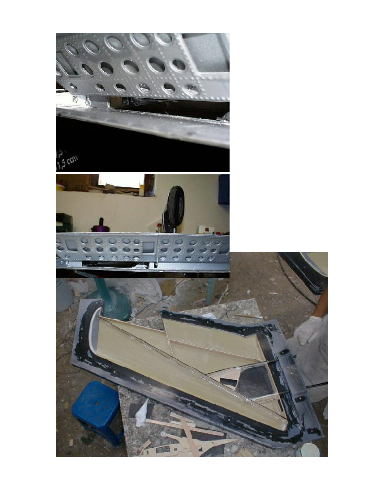
See the photos of a finished
flap. If youinstall thevacuum
formed sheet you should
prepareit with the holes shown
in the photos. The effect you
get is 100%realistic. Us a few
triangle balsa wood ribs to
stiffen thevacuum formed
sheet. But make sure that
these ribs areplaced in the
areas between the holes.
The bottom photoshows the
intermal constructionof your
wings,so that you will get a
better understanding where
everything hasto beplaced. It
shows the landing gearmount
and therib, where to place the
aileronservo.
Page 19
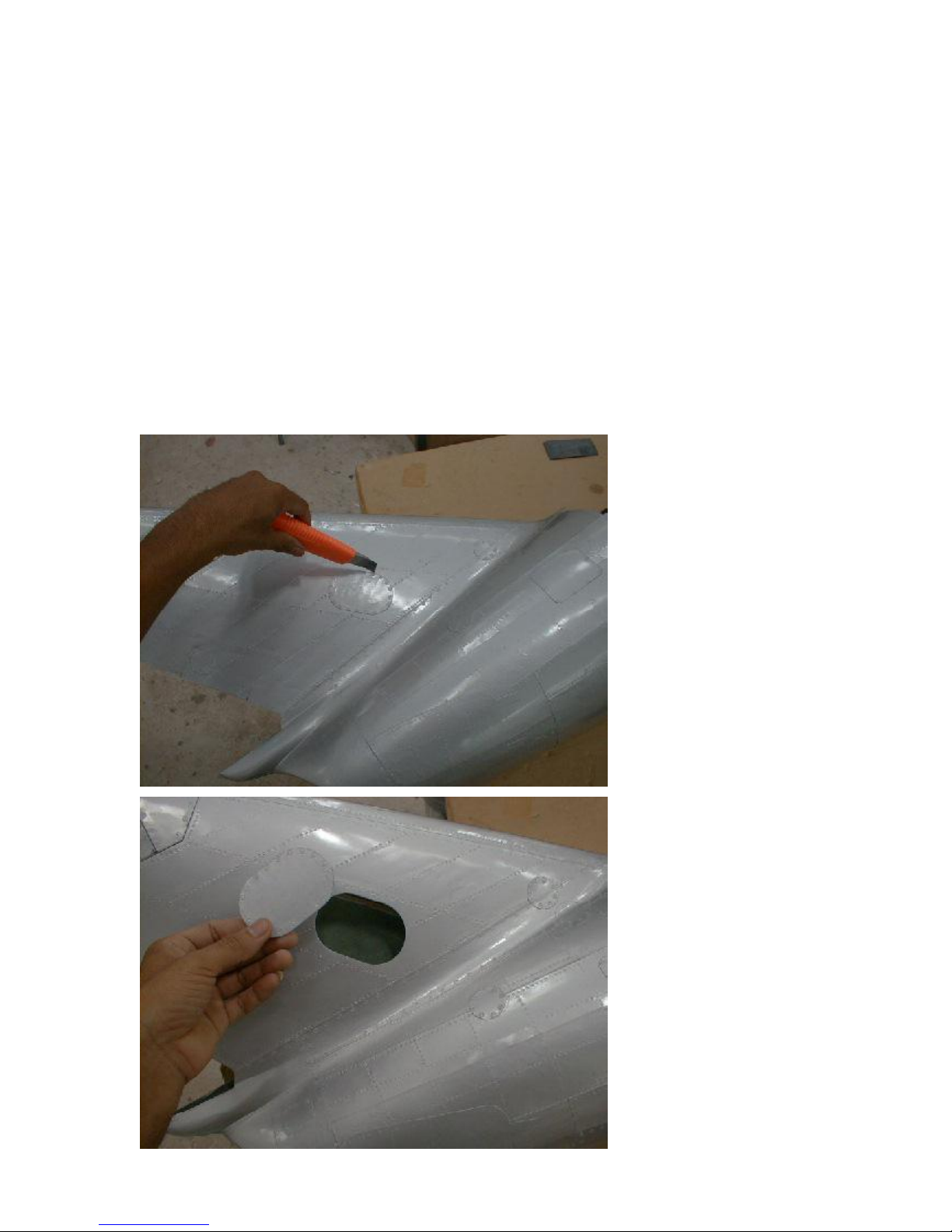
5. bottom rudder and servo installation
Work Steps:
- Cut the hatch and shape the parts to fit the rudder
- install the rudder with Robart hinges and torsion linkage
- set up the servo linkage and mount the servo and hatch
You need:
- cutter,dremel milling tool, round file, drill bit 5mm
- CA Glue, Epoxy glue with some milled fibre
- fuselage, one-piece-stab, bottom rudder
- milled rudder servo mount, 3 robart hinges, torsion linkage,
2 pushrods 2mm, 2 clevises M2, 2 threaded ends M2,
rudder servo, extension servo lead, 2 sheet metal screws
YourMiG-15 has only the
bottom rudderworking. the top
rudderis fixed. This simplifies
the system very much, and at
the same time reduces the
chancesof flutter.The one
bottom rudder isvery efficient,
sothat you wouldnever feel
the needfor the top rudder
workingas well.
Start withcutting the servo
hatch. both sidesof the rudder
fin showsa hatch in the center.
Whichever oneyou pick, is up
to you. Cut one hatch out with
an X-Acto knife.
At that time youcan install
alreadythe frame, to mount
the hatch lateron. 2 scrap
piecesof thin plywood dothe
job, just glued in on the top
and bottom radius of the hand
hole. Use2 sheet metal
screws, one each at the top
and bottom radius to fix the
hatch.
Page 20
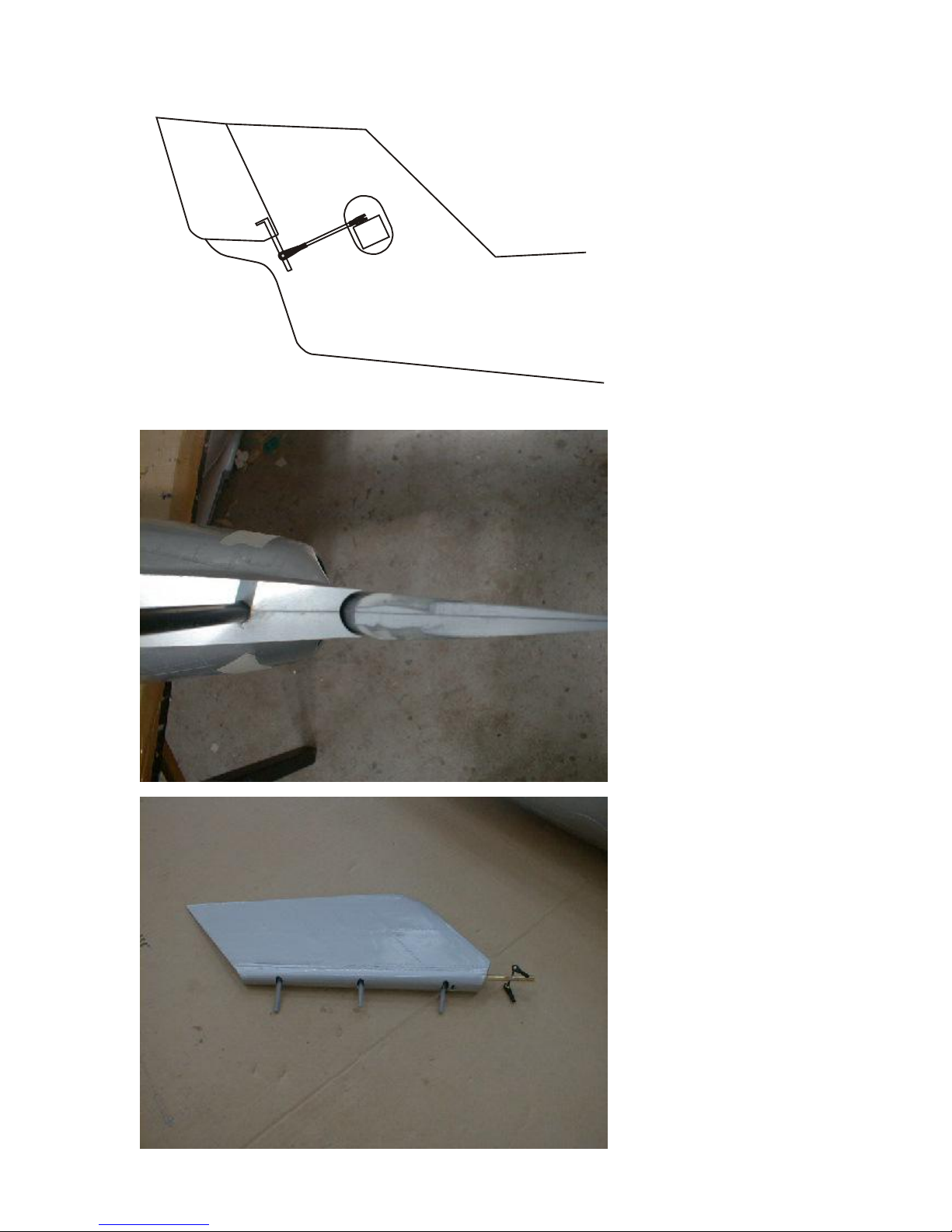
Youwill have to cut some
areas of the rudder fin and the
one-piece-stab to acceptthe
roundedleading edge of the
rudder. Thesecutouts could
not be molded in for production
reasons.
Cut both parts according to the
photos, assemble the parts to
confirm sufficient clearance,so
that therudder canmove
withouthittingany otherpart.
Better make thesecutouts too
big ratherthan too small.
Nowinstall the Robart hinges
into the rudder.Youhave done
this with the ailerons
successfully, so go ahead and
do the same thing with the
rudder now.
As the rudder is wider, the
slots,which give the hinges
clearance to move, must be
longer as well.
Torecall, drill the holes with a
5 mm drill bit, open the holesin
the fiberglass with a small
roundfile to ret oval slots,and
insert the hinges with epoxy
glue. (Do NOT useCAglue!!!)
Then make the cutout for the
torsion linkage.This linkage is
insertedfrom the front, so cut
the leading edgeof the rudder
accordingly to the shape of the
torsion linkage. Mill a 2 mm
wide slot in the woodspar of
the rudder, andinsert the
torsionlinkage withplenty of
epoxy glue. See dimensions
given in the photo.
20 mm
Page 21
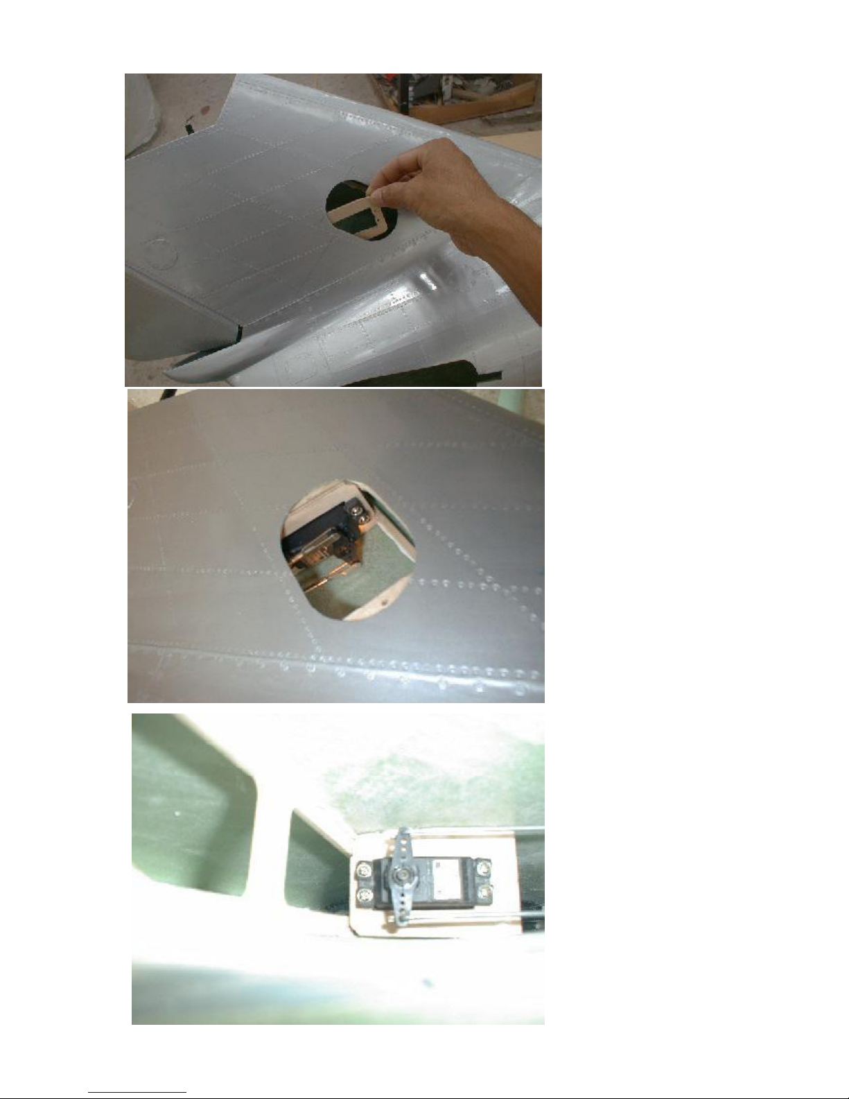
The rudder servo is mounted
upsidedown in the rudder fin.
Place theservo mount (3mm
milledplywood)in thefin.
Make surethat the rudder
linkage canconnect the torsion
linkage of the rudder and the
servo hornin a straightline
and perpendicular to the
ruddersaxis of rotation. This
essential need gives youthe
right positionfor the servo
mount.
Glue this servo mount in with
eloxy and milled fibre.
You caninsert and mount the
rudderservo through the side
hatch, and tighten theservo
screwsthrough the fuselage
from the bottom side.
Make up the linkages with the
correct length. Solder the
threaded ends to the 2 mm
push rod and connect turn the
push rods about
1/4 “ into the plastic ball links
of the torsion linkage. Now
installtheservo finally.
The bottom photo showsa
version whichdoes not call for
a soldering iron... you can also
Z-crimp the endsof the
pushrodsand connect them to
the servo hornby this method.
Adjustment is still given by the
plastic ball links.
Page 22
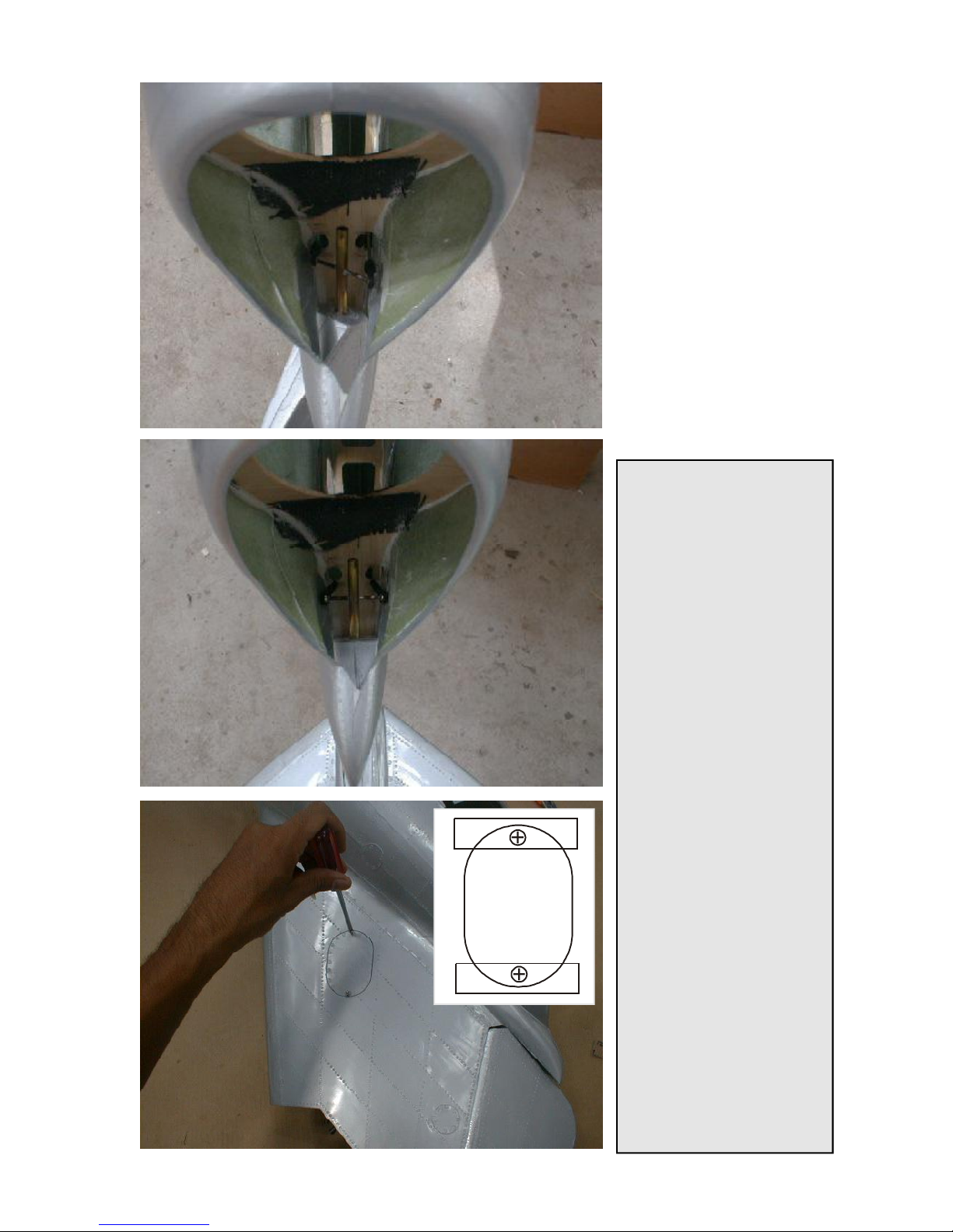
These photosshow, where to
cut or drill the holesfor the
linkage to passthe rudder
post. These holes should be
fairly large, sothat the linkage
does not bend ot lock at any
position.
When all is done and adjusted,
drill the holes for thehinges
into the rudderpost of the
fuselage and insert the rudder
byapplying epoxy glue to the
hinges.
After theglue hascured, finally
installthe linkage and confirn
thefree movementto both
sides.
Tip for the Pro’s:
This type of linkageis basically
a pull pull set up. the only
differenceis that not flexible
wires, but 2mmpushrods are
used. So, it could also be a
push/pushlinkage, which can
build up a very strong tension
in the system, if not done right.
To set this type of linkage up
properly you have to adjust the
length of both pushrods
exactly, before you install the
servo horn to the servo. If all is
tension free, the servo horn will
slide on the servo axle easily,
after thewhole linkage is set
up. Last thing is then to put in
and tighten the center screw.
Youmight use some thread
locker to makesure that the
screw doesn’tcome loose.
Do not makea support at the
bottom end of the torsion
linkage, as the angles of the 2
pushrods are not exactly
parallel, and it would buildup a
very dangeroustension at
maximum travel, if the rudder
torsion linkagedidn’t have a
slight flexibility. There is no
one-way-loadon the bottom
point of the torsion linkage, as
all force pulling on the one
side, the sameforce is pushing
in the opposite direction on
the other side.
Page 23
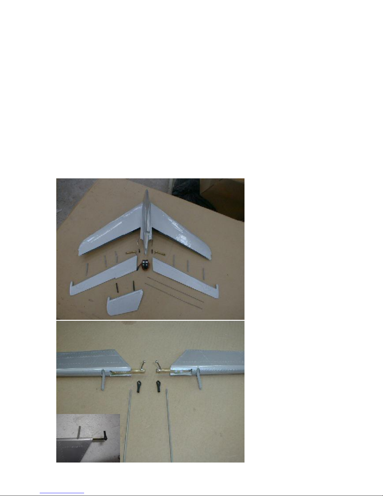
7. Elevator and Top Rudder
Work Steps:
- install the hinges and torsion linkage in the elevator
- install the elevator servos and set up the linkage
- glue elevator in and glue in the fixed part of rudder
You need:
- 5 mm drill bit, dremel milling tool, philips screw driver
small pliers, small round file, sand paper
- epoxy glue, CA-Glue
- one-piece-stab, both elevators, top rudder
- 2 torsion linkages, 6 hinges, 2 carbon dowels, M2 push rods,
2 clevises M2, 2 threaded ends M2, 2 elevator mini servos
The elevator servosare
hooked to a hidden torsion
linkage, which does not
interfere withany scale
ambitions in regards to static
judging. This torsion linkage is
gluedinto theelevator
controls.
Start withmounting this torsion
linkage andthe Robart hinge
pins into the elevators. Youdid
the same thing with the rudder
already, sofollow these steps
accordingly again.
Drill the holes in the spars of
the one-piece-stab and trial
mount theelevatorsto the
stab. Use the same directions
asgiven onthe aileron mount,
resp. the angle of the hinges,
so that you can assemble the
elevators and the stabdue to
the swept back shape.After
that cut the center hole as
shown in the drawing, to have
accessto the servo area inside
the stab.
Move the elevatorscarfully,
and look inside to se whether
the balls of the torsionlinkage
hit the fiberglasssomewhere.
Youmight have to bend the
steel arm of the torsion linkage
slightly to manage a smooth
travel.
Inside the stab there is a
vertical spar.There are
premilled holesinside, which
size might have tobe
enlarged, so that the linkage
can beput through.
Page 24
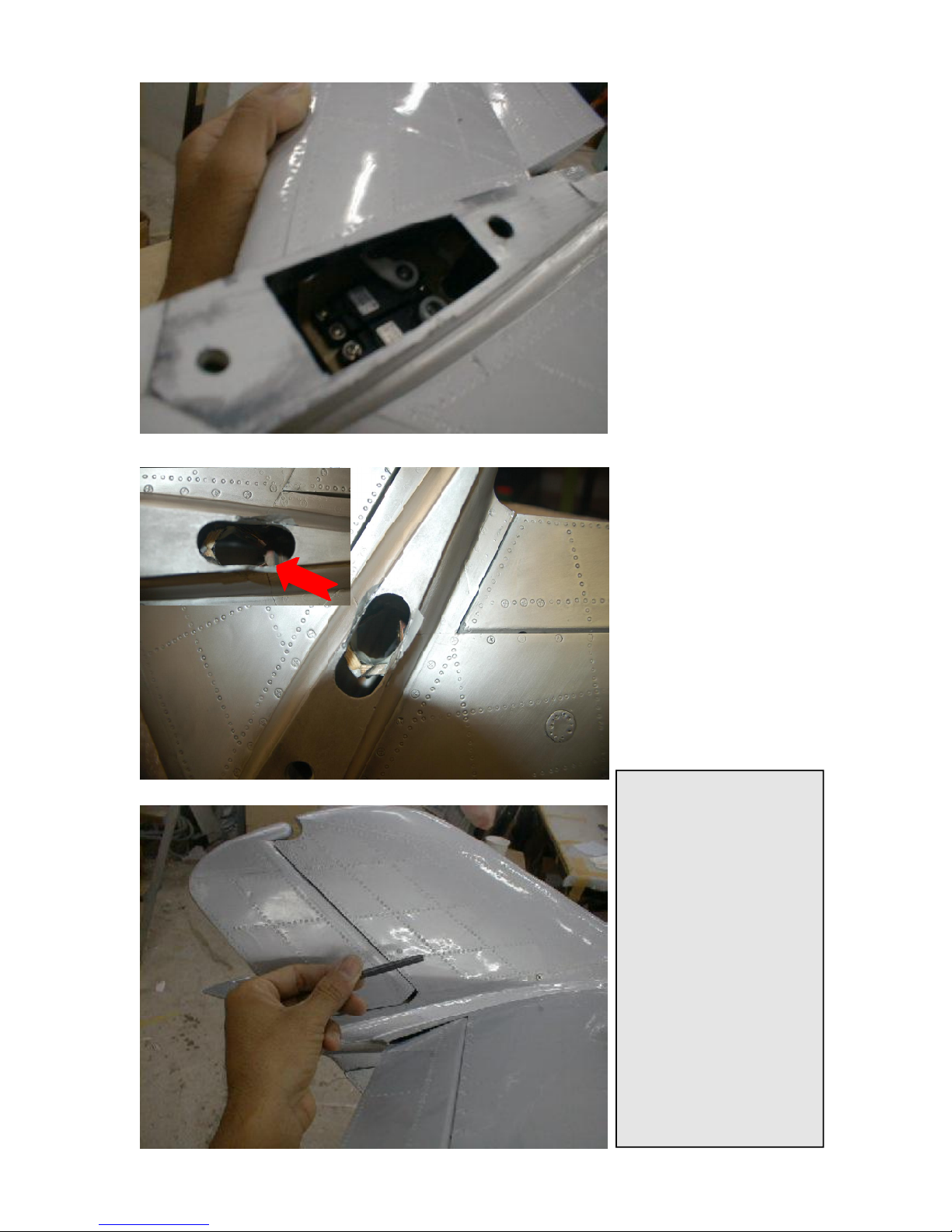
Nowinstall the servoswith
shortservo arms into the servo
mount. Youwill have to make
sure that the servo arms do
not hit thefiberglass.It is very
tight inside, and it might afford
several attemptsto install
servos and linkages so that
everytingmoves smoothly.
After the linkage is set up with
ball links, pushrods, threaded
endsand clevisesin the right
length,assembleeverything
againand confirm. After that
takeout the elevators again
and apply epoxy glueto the
hinges,and glue them in
permanently.
To reduce the play and the risk
of a flutter it is recomended to
additionally hinge thetorsion
rods in the center. Use a 3mm
plywoodpice for this anddrill a
6.1mm hole in wherethe
torsion rodsare hinged in.
Glue this pice againstthe stab
spar.
The top rudder part is fixed
mounted to thefin. Drill two
6mm holes in each rudder and
fin, and glue the carbondowels
in. Then join the 2 parts and
gluepermanently withepoxy.
Tip for the Pro’s:
Whenever you finally mount a
servo intoa difficult accessible
area, make sure that the servo
arm is properly centered.
Therefore connect the servo to
a receiver and center th servo
electronically. Adjust theservo
arm perpendicluar to the
linkagedirection, andthen
mount the servo finally.
If you don’t do that, you might
have a bad surprise after you
hooked up your radio system.
When the servo arms are out
of center,you will haveto take
out the servoagain, which is a
very painfuljob, if everything
else isfinished already. Think
smart inadvance!!
Page 25
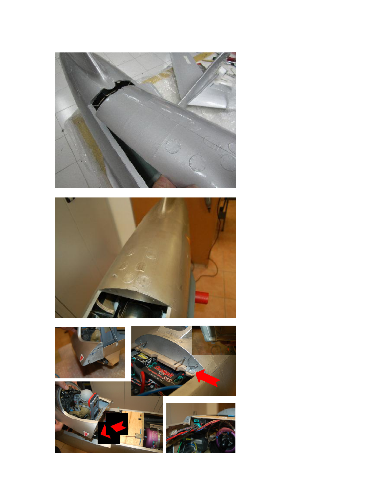
7. Fuselage hatches
Start with fittingthe rear hatch
to the fuselage. Sand the rear
end of the hatch andthe fillet
of the rudder fin so that
everything fits nicely.Do not
worry to sand off some
material in the vertical frame
areas,especially rounding
corners, the fiberglassis thick
enoughin these areas.
Also the little cornersof the
stepsin the center area of the
hatch needto be sanded
slightly,so that thehatch gets
a clean and proper fit.
This rear hatch nowgets glued
onthe fuselagepermanently.
Use30-min Epoxy and milled
fiber for theglue joint.
The hatch withthe cockpit gets
2 6mm carbon dowels in the
back and getsscrewd on a
3mm plywood support with 2 LShapealluminium bracketsin
the front. This part is the one
which usually does notneed to
be takenoff once the plane is
puttogether atthe airfield.
On thepicture you already see
the piano wireswhich lock the
centerhatch covering the
enginearea.
Page 26
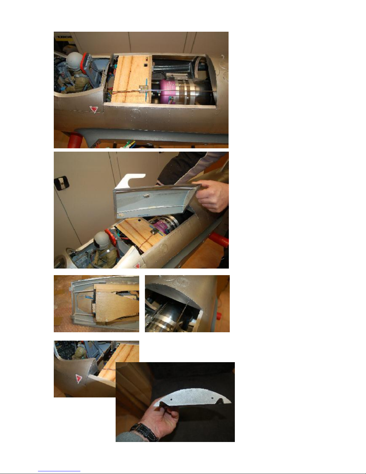
The center hatch which covers
the engineis locked by two
piano wires running all the way
from the small hatch at the
nose into the rear hatch which
wepermanently glued on in an
earlier stage.
The piano wire runs through
the white 2mm ID plastic
tubing.
It is recomendedto glue the
plastic support rails to the
hatcheson various points for
support.Youdo not needto
glue them all the way through.
Toallow a smooth opperation
make sure not to bend the pinline more then absolutely
necessary.The more it is bend
the harder the pins will slide
throughlater.
The nose hatch needs to be
cut asshown in the rear to give
the clearancefor the pianopins that hold the center
enginehatch.
Page 27
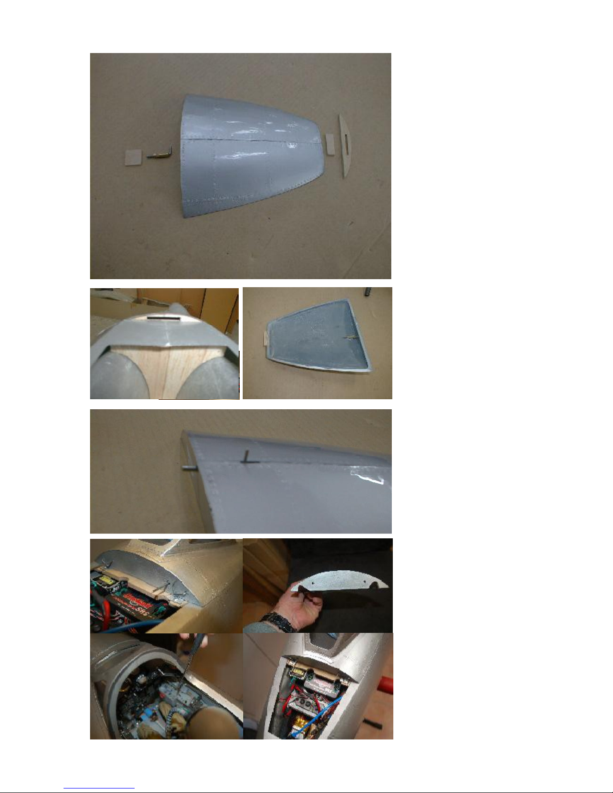
The nosehatch is a small
challengeonly.The3 milled
plywoodpartshave to be glued
in placeAlso glue in the hatch
latch. Make surethat the slot
for the latch is long enough, so
that you can release the hatch
easily. The pin must disappear
in the hole completely,when
you pull it back.
Asa helpful hint, you might drill
the hole for the hatch latch pin
whenall is taped on the
fuselage. So you can make
sure that the wholesare
allignedperfectly.
Todo this, you will have to cut
outthe canopybefore finishing
this step. We explain this on
the next page.
Doing this, youcan insert a
dremel throughthe canopy
cutoutsand drill the holefor
the pin throughall in one time.
Check the proper fit of the
hatch, and make surethat it is
removable withoutlocking or
hitting.
This is your only real quick
accesshatch for any switches
or connectors, which you might
needat the field to start up
your engineor check radio and
landing gear. For more access
to thecomponents you will
have to unscrewthe large
hatch.
if you do not wantto show the
canopyhatch latch as
discribed abovebut rather
want the nose hatch latch to be
invisible as well, you can do it
the saneway as we did the
center hatch usuing the piano
wiresand plastic tubing. In this
case, to lock an unlock the
hatch you slide the pins inside
the cockpit as shown in the 4
bottom pictures.
Page 28
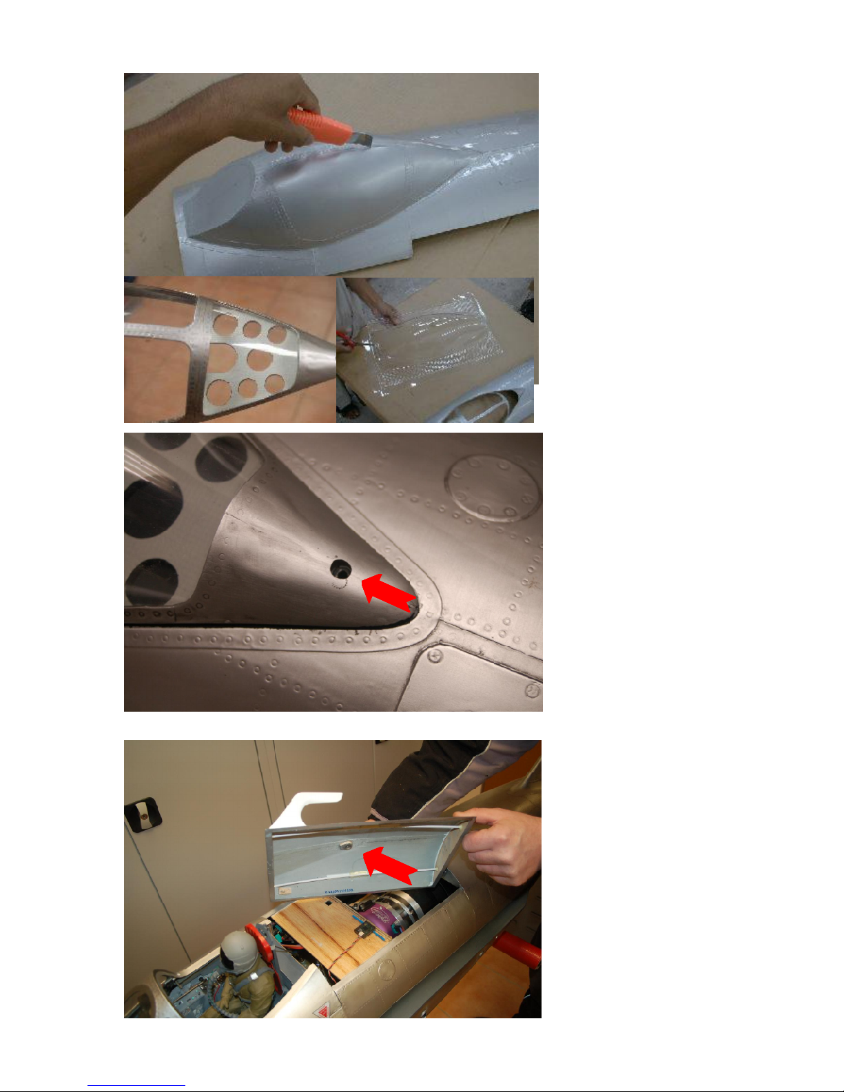
Cutting out the canopy works
best with a very sharp X-Acto
knife. The layup in this area is
very thin, so be careful not to
cut into the frames.
After cutting out the windows
roughly, useroundedfile and
sand paper sticks to finish the
cutting borders.
After that cut out the clear
canopy.We still believe that
the best way to do it is to use
sharp scissors. To avoid
cracking of the canopy you
maywarm up alittle.
After cutting thecanopy
roughly put it into the canopy
frame from the inside. Now
you can determine theexact
cutting lines, to make aperfect
fit
Aso the rear wood support
plate and little detailing canbe
glued in at this stage.
The canopyframe gets2 piano
wire pinsin the front edge
corners and gets secured with
an M3 screwat the back.
Therefor a blinde nut gets
glued into the center hatch with
a pice of scrap balsa or
plywood.
Page 29
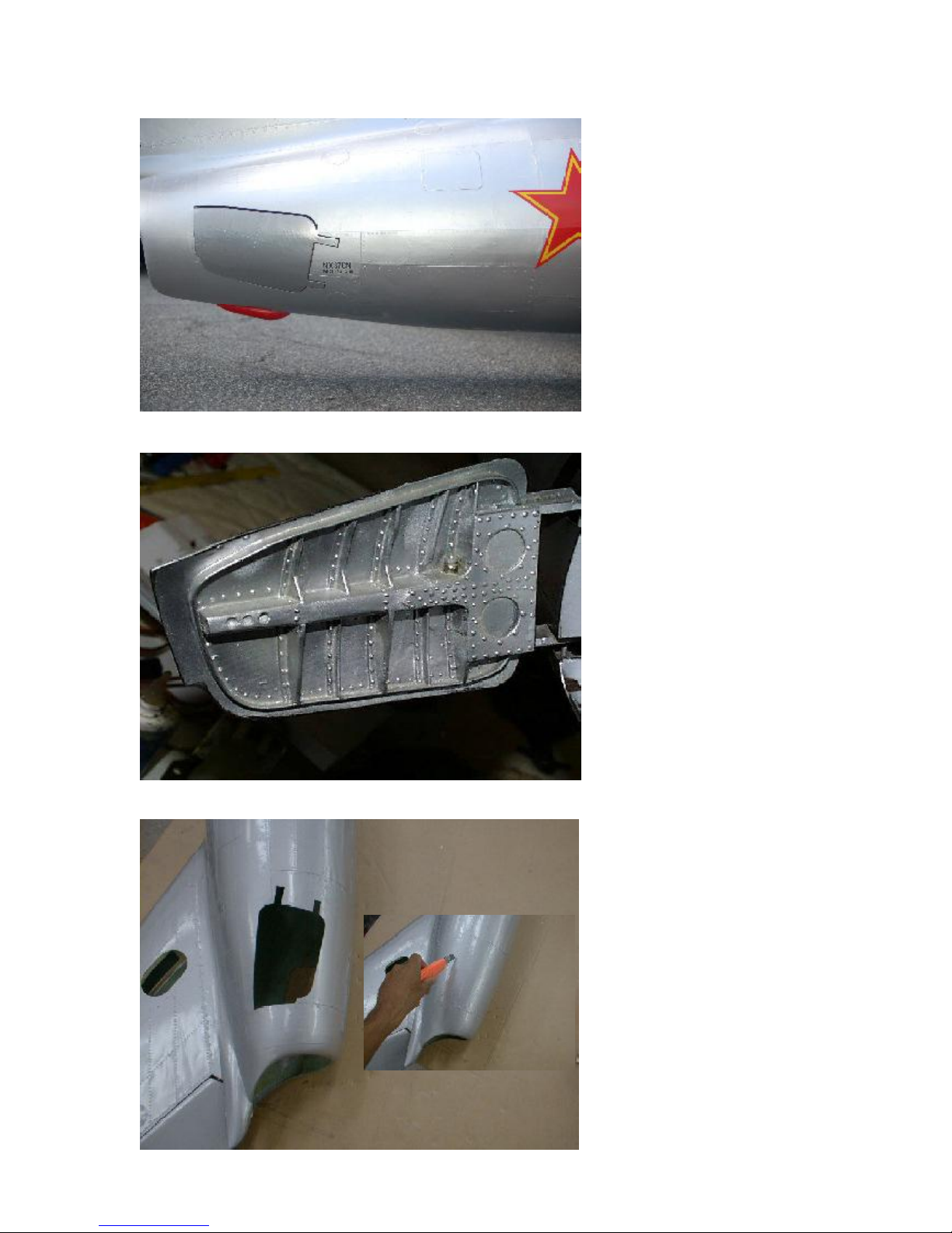
8. Speed brake doors
This is again a workingstep
demanding a good amount of
skills and
PATIENCE.
First, cut out the 2 speedbrake
doors at the rear end of the
fuselage.Youcandetermine
the shapeby checking the
panellines. They arecorrect
and do not need any further
modification.After you cutout
the doors, sand the cut slightly,
and make surethat your cut is
not too wide.That’s whywe
recommend to usea cutter
blade only. Do not use any
electric milling toolsat that
stage.
If you do not want to operate
the speedbrake doors in
flight, you canskip this
whole chapter8.
But a plane that scale
should definitely havethe
speedbrake doorsworking,
and they are very efficient
too.
They work more neutral
than the flaps, and for that
reasonthey arehighly
recommended!
Page 30
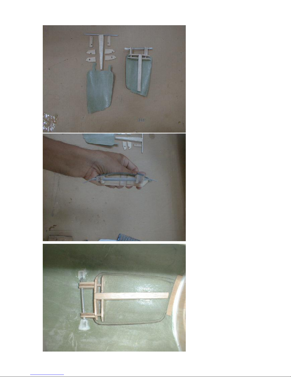
Makeyourself confident with
the parts.All items are
suppliedwith the kit. The photo
on the left shows a set of parts
and an assembled speed
brake door.
The next photo explains, how
the axle has to be placed.
Basically it is a 4 mm
aluminum tube, with flat ends,
curved accordingto the
fuselage’sshape. So, slide the
tube throughthe holes in the
ply mountsand shorten,crimp
and bendit as needed.
Fix the wholeunit in the
fuselage, using only a few
dropsof thick CA glue.
After you confirmedthe
movement is alrightyou glue
all withepoxy and milled fibre.
Toreinforce the bondyou
shouldadditionallycoverthe
bond with some scrap pieces
of fiberglass.
If necessary, you can now
sand the corners and edges
slightly. Especially in the hinge
areayou might have toremove
some more material, to make
thedoor moving without
locking in this area.
After all is set,glue a small
strip of 0.8 mm plywood inside
the fuselage, at the rearend of
the speed brake door, as
shown in the photo.
Page 31
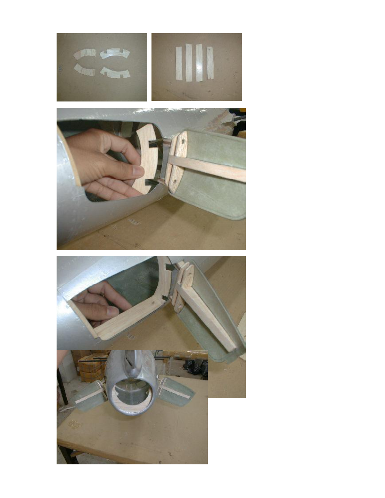
Next step is to frame the inside
of the speedbrake doors.
Milled balsa parts aresupplied
with the kit. Follow the photos
to install theseframes in the
fuselage.
At this stage, do not gluein the
innercover.Leave the area
open, until the air cylinder and
further detailingare installedin
the door setup.
UseCA glue to gluethe frame
in. Youmight have toreshape
the parts slightly.Make sure
that the frame does not put any
tension on the fuselagesskin
in this area, so that the speed
brake doorcloses smoothly
withoutany gap.
Page 32
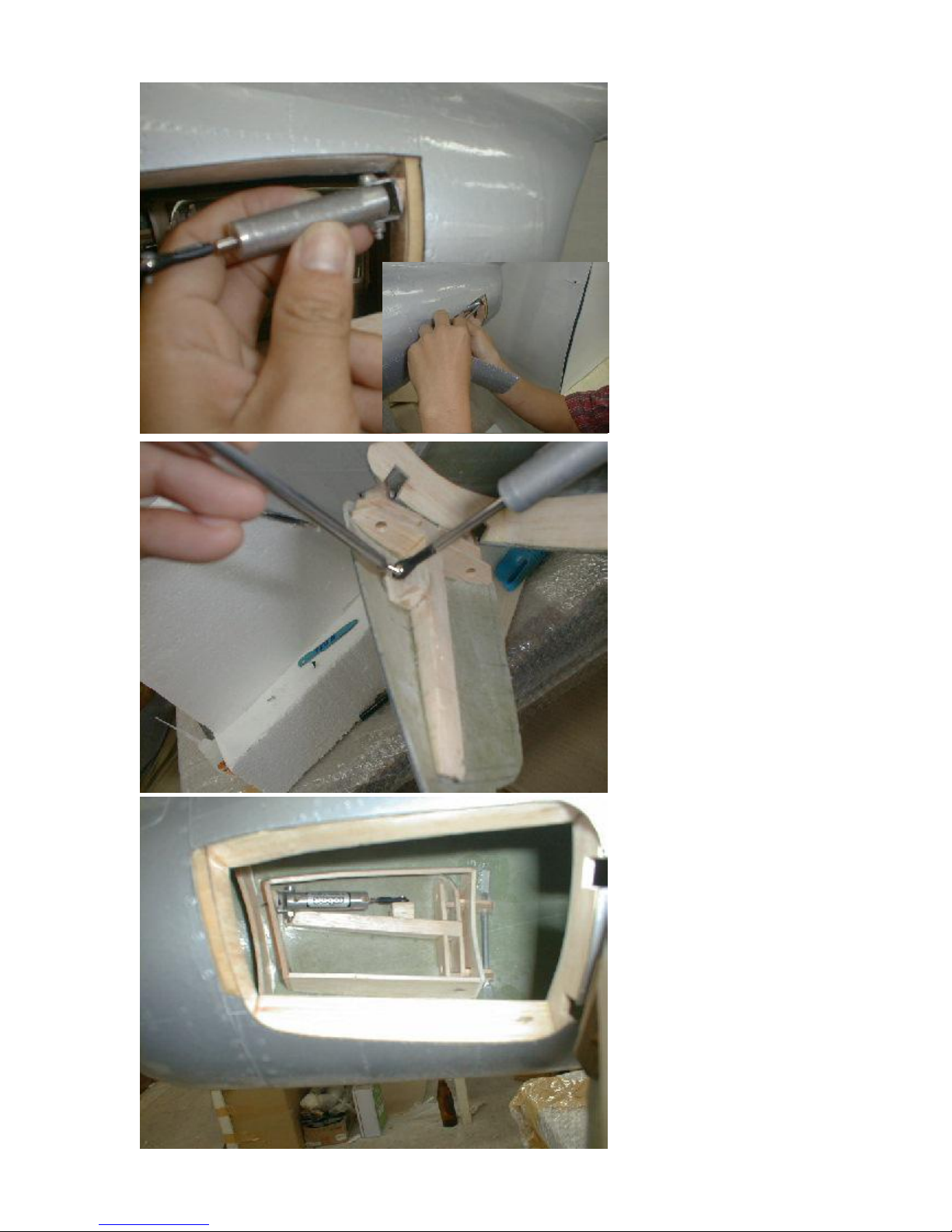
Nowinstall theair cylinder for
the speed brakes.
Locate the position in the top
rear corner of the frame.
Reinforce this area with thin
plywoodfrom the back side,
and mountthe cylinder with
sheet metal screws. Note, that
thecylinder ispointed a little bit
downwards,so you will have to
usea little balsa woodtriangle
as a spacer.
In general,the sloppier this
mount is, the better it will work.
Don’t worry about clearancein
this mount, as the cylinder also
must move slightly upand
down,not only in andout.
Install the ball link to thepush
rod, and adjust and confirm the
correctlength.
The speed brakes should open
approx 45 deg. So you
determine the fix point where
to mount the ball of the ball link
inside the door.Reinforce this
area withanother balsa block
and mount the ball with a small
sheet metal screws.
After themovement is
confirmed, harden the area
wherethe ball is mounted with
thin CA glue.
See the bottom photo for
further reference.
Page 33
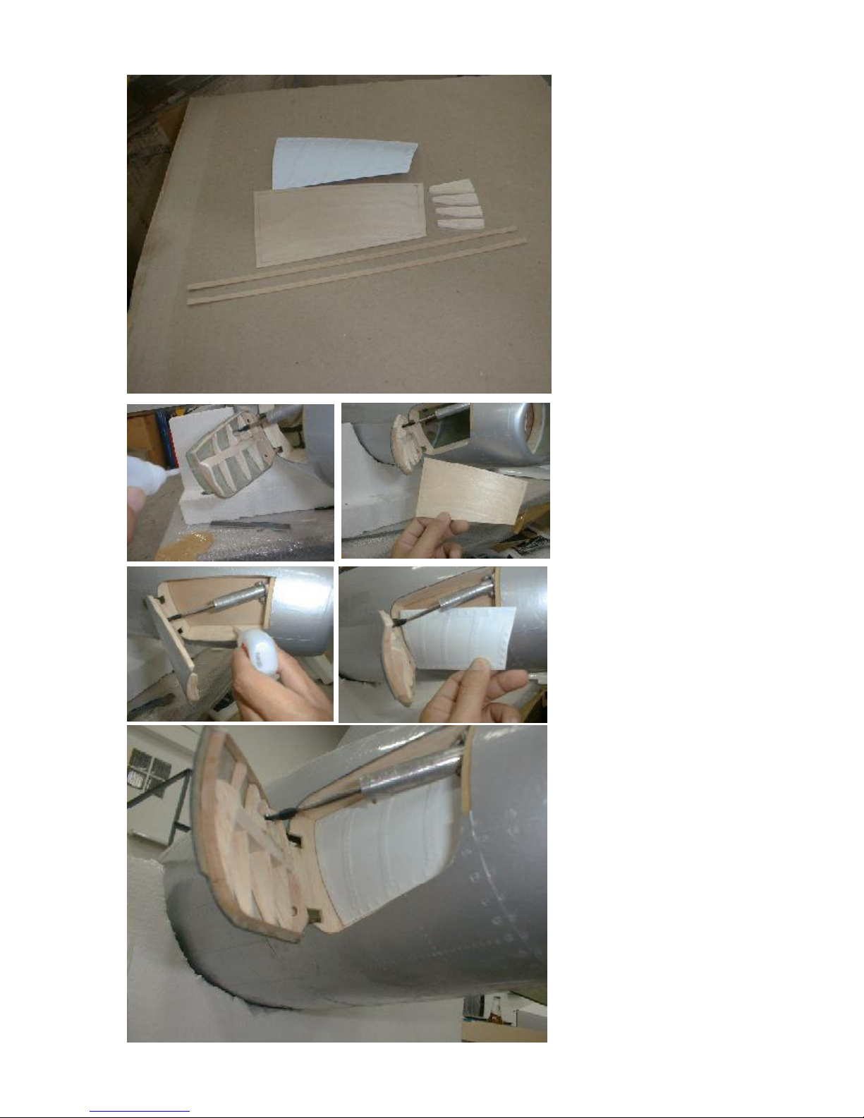
Further detailing isleft up to
you. We recommend at least
cover the frame with the 0.8
mm plywoodsheet.
See the photo for further
detailing of theinside of the
speedbrake door. This
detailingis basicallya very thin
frame of plywood, 3 mm (1/
8th”) high, andthen filled with 2
additional ribs,which youcan
cut from 3mm balsa.
Useprimer to fill the balsa,and
build up a goodbase coat for a
laterpainting.
Glue the thin plywoodfrom the
inside against the frame. Use
CAglue. After that youcan fit
thevacuum formed detail in
the frame and glue it to the
plywoodbackplate.
The movement of thespeed
brake door is done by an air
cylinder.Althoughyou might
think that the setupand angle
of the cylinder is correct, as all
moves smothly when you
move by hand, try toapply
pressure air to the cylinder,
and double check whether all
moves as smoothly when the
cylinder doesit’sjob. It might
bedifferent. So you might have
to sanda little more on the
contours of the speed brake
door, andyou moght have to
changethe mounting pointsof
thecylinder slightly.This iswhy
werecommend to permanently
fix everythingAFTERyou
testedthe movementwith air!
Page 34
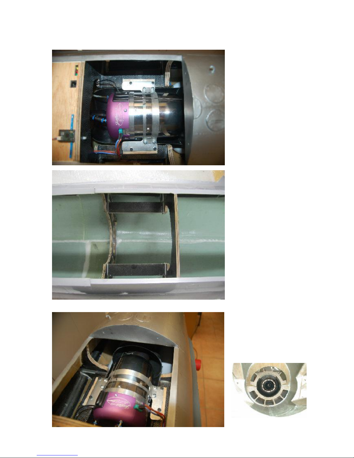
9. Engine installation
First of all, we showthe
installation of a JetCat P120SX.
If you use other engine brands,
go ahead. Any engine between
8.5 and 12 kg of thrust will do
fine.
We do not mention the
installationof theadditional
componentssuch as fuel
pump, gastank, valves, andso
on, asany engine requires
different accessories.
Wheneverthe pictureswill give
you an idea of whereit might
makes senceto install certain
components.
CG-matters might require to
move these components
around in the fuselage, sowe
recommend to install these as
theverylast.
The Enging Mounting rails are
alreadypre-installed, sothe
position for the Engine is given
bythat position.Installation of
the engine be a naturalthing,
too. It mounts on the
preinstalledrails, by using the
supplied M4 x 16 screwsand
M4 T-nuts.
Assemblethe ducting first.
Glue the rearcone into the
bottom duct (the one with the
mounting bracketsmolded in).
Mount the stainless thrust tube
to the rear end of the cone,
and slide the wholeunit into
the fuselage. Rear end of the
thrust tubeis held by the rear
former. Install a plywood piece
in the rearend of the fuselage,
to mountthe outer aluminum
tube to with just one sheet
metal screw. Basically the tube
is held by the mounting screws
to the carbon cone in the front.
This rear fixture is just for
avoiding thealuminum tubeto
slideout.
Check allignment!
Page 35
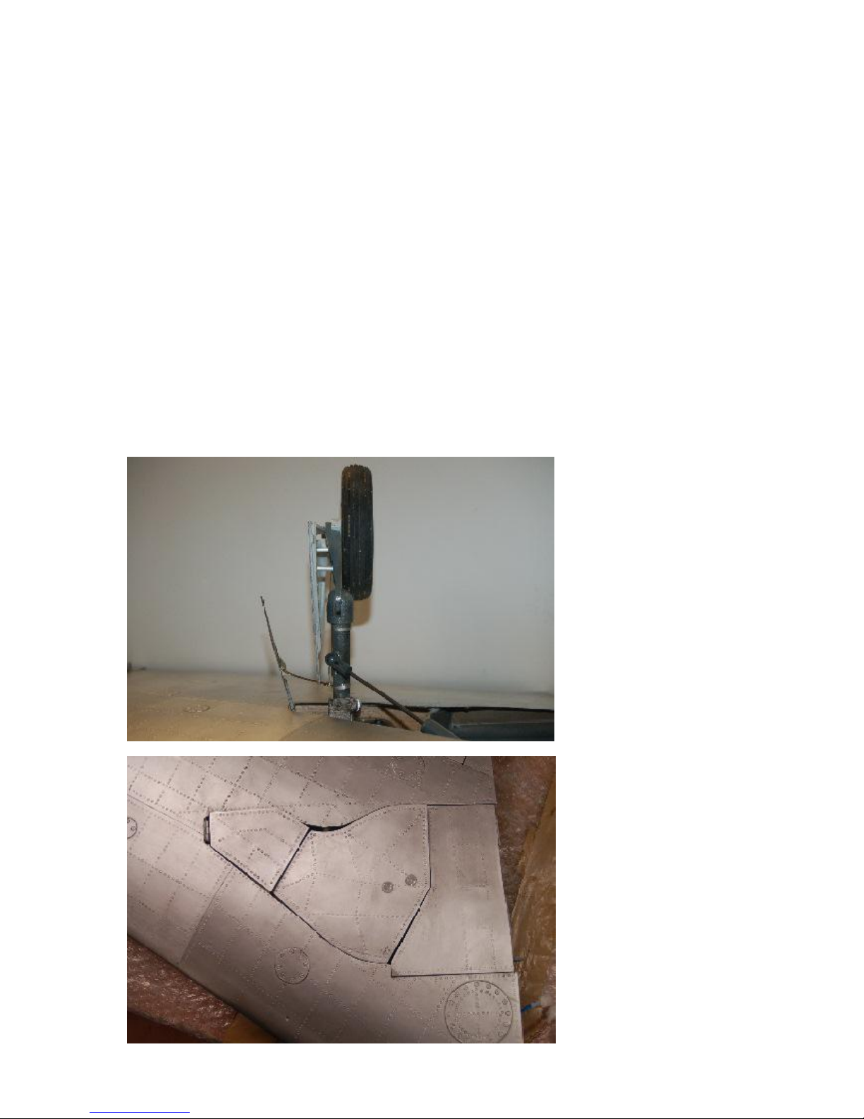
10. Main Gear & Doors
Work steps:
- fit the gear units into the mounts
- install struts, brakes and wheels
- mount the gear with each 4 M4 screws
- install the support air cylinder
- install small outer gear door and linkage
- install main gear door to the gear strut
- detail with vacuum formed sheets
- install inner gear door to fuselage
-install detailing
- build cylinder mounts and install gear door cylinders
If everything wentwell upto
that state of construction,you
finally reachedthe most
challenging point right now. It
took usmonths to determine
the correct angles of the
landing gearmounts, struts,
wheelsand all, and still some
work is left up to you, as
manufacturing tolerancesdo
notallow topreseteverything.
There is still a slight amount of
“try and error’to be figured out,
and the gear unitsmight have
to be supported by thin
plywood sheets,acting as
spacers and angle adjusters,
downto the thickness of thin
cardboard,even this canmake
a difference whetherthe
angles will work out or not.
So please accept, that we will
have to askyou for patience
again,but hopefully thelast
time, to set everything right. Do
not expect it to be done in a
sundayafternoon. It takes
more time to do it right, but the
result is a very strong, reliable
gear system, which is 100%
scalein outfit andfunction.
Also the gear doorsare
detailed inside and outsideas
the original ones,and give the
plane the 100% authentic look
on the ground.
Page 36
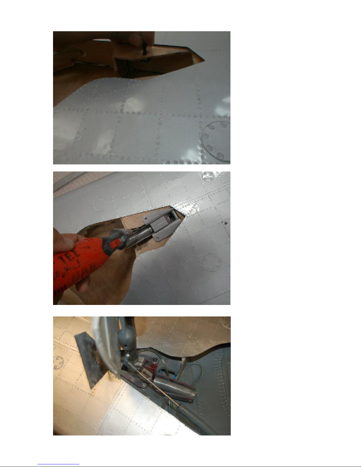
Let’sget startedwith mounting
the gear units. Cut out the
gear cutout in the former
approx. 10 mm further. (first
productionrun kitsonly!). Slide
the unit in, and see where to
girnd off the plywoodsupport
rib, to fit thecylinderperfectly.
The cutout in this rib isvery
small on purpose. Otherwiseit
could not inserted straight
whenwe assemble the wood
partsbefore joining the molds.
It is upto you and yourdremel
now, within a few minutes to
enlarge the cutout to fit the
gearperfectly.
After that trial mount the strut
and check where else you
need to takeoff some plywood
in the mount area.
After that take out the unit
again and glue in the
rectagularplywoodreinforcementsfrom the bottom side of
themounting platform, about
wherethe screwswill hold the
flanges of the gear unit. This
means, you double up the
thicknessof the plywood in
that area,to give theT-nuts
some more materials to hold
in.
Beforeyou finally drill the
holes, assemble the gear with
strut, wheels and brakes, and
check howit fits in the gear
wells. If necessary, you might
have to grindthe cutout in the
mounting platform anotherfew
milimeters, and move the gear
slightlymore out.
Page 37
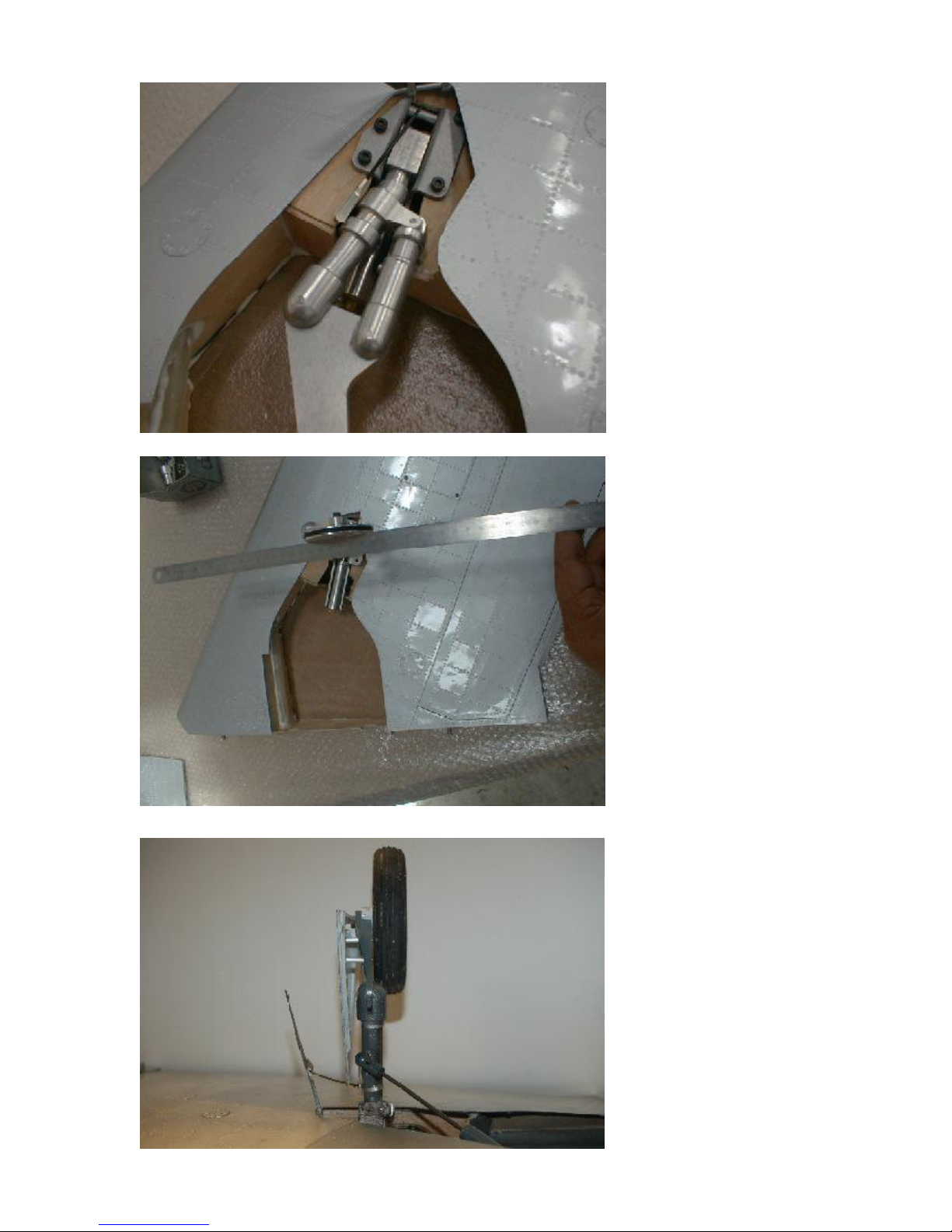
After it isconfirmed that the
gear fits the gear well, mark
the position of the holes for the
mounting screws witha pencil,
and takethe gear out.
Then drill 5.5 mm holes,insert
theT-nuts and trial mount the
landinggear.
Nowmove the gear strut in
and out, to simulate a
retracting cycle.Youseenow,
howmany angles have to be
correct, so that the wheel is
- flat and parallel in the gear
wells, when retracted
- parallel to the root rib
whenextended,
- not hitting anythingduring
the retracting cycle
that the strut is
- exactly correct positioned
in the gear wellswhen
retracted
- hiddenunder the bottom
wingsurface, to accept the
gear doorsalligned to the
bottom wing contour
- exactly vertical in side
view, when extended
- exactly vertical in the front
view, when extended.
and finally,that the gearunit is
low enough, that it can be
covered withthe outer small
gear door, which will have to
be connected with themain
strut.
The front two monting screws
are counter sink screws to
allow the small gear door to
close propperly,there is not
enounghroom for regular allan
heads. The 2 rear screws are
regular M4x20allan hed
screws.
Page 38
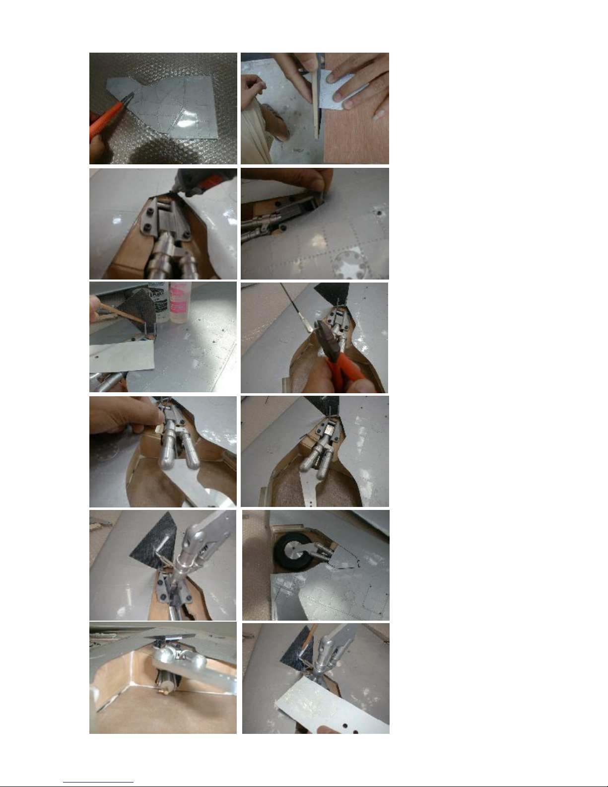
When the movement of the
gear units is exactly as you
want it to be, get started with
the outer small gear door. The
angles of this small gear door
arevery complicated aswell.
Basically,it is hingedwith 2
Robart hinges, and connected
to the strut by a 2mm rod,
which has a clevis on on the
strut side, and a 90 deg. bent
angle onthe door side, which
slidesinto a plastic tube, which
has to be glued to the door in
theexactly right positionand
angle.
We use a “pull pull threaded
end” screwed into the M3
thread of the strut. In that the
cleviswill belinked.
The linkage is so short, that
youeven might have tocut the
clevisslightly,for sureyouwill
hardly be able to use the
thread as a length adjuster. Fix
the white plastic tube with a
veeery little bitof CA to the
gear door and startmoving the
gear in and out.
Doingthis, youwill realize
quickly,howdelicate the setup
is, and all angles of the linkage
and of the tube are responsible
for the correct angel of the
gear door in extended and
retractedposition.
Don’t give up,after 50
attempts you will getit right,
and from then on it will always
workwithout anyfurther
adjustments.
Finally fill the jointsof thehinge
withepoxy.
Page 39
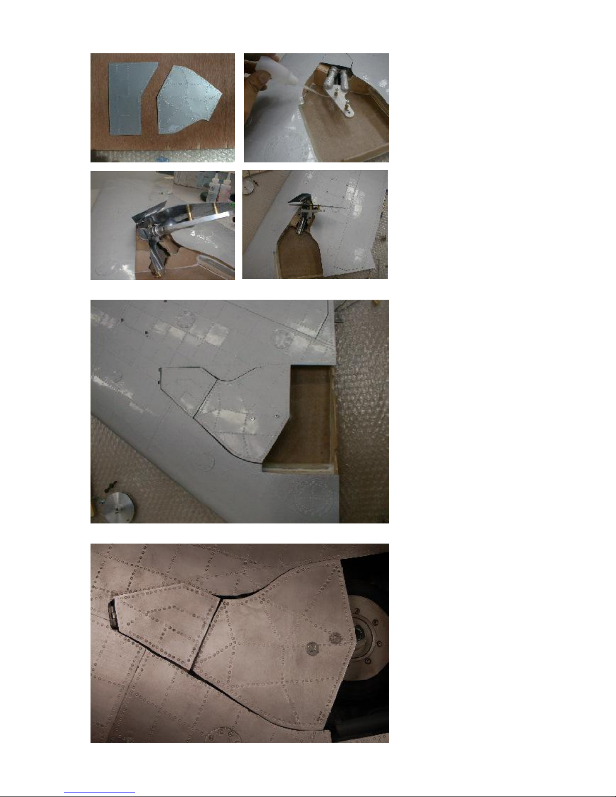
A slightly easier job is
mounting the main geardoor
to the strut. The M3 threads
are in already, andyou now
have to adjustthe length of the
brass tubes, which are used as
spacers between strut and
gear door.
You can take off wheel and
brakes at that stage.
Mark the holes on the gear
door and drill with 3mm.
Mount the geardoors with the
M3 screws, andallign
everything withthe gear well,
whenretracted.
When you move the strut now
in and out, you must check if
the outer gear door hits and
looks against the main gear
door. If so,you will have to
readjust the outer gear door
againa very little bit, or move
the main gear door down a
little.
Now you should build a few
frame surfaces into the gear
door, wherethe main gear
door rests on when retracted.
Make sure,that the wheel
does not hit these frame parts
duringthe cycle.
After all fits, mount thewheel
with brake again, and take the
gear door off.
Next step is to glue on the
inner door details, madefrom
vacuum formed styrene.
Page 40

Cut out the styreneparts and
sand the shape, sothat they fit
on the gear doors well. Glue
them on with a few drops of CA
glue.
If you glueonly in the topand
bottom center area, you can
later bendthe geardoor a little,
to get perfectly matching fit in
the wing, and then gluethe
rest with CA glue. If you glue
all in onestep, you might warp
the door, so that it does not fit
anymore.
Assembleall again, and
double check all again.At that
time you shouldalso take the
inner geardoor, whichis going
to be mounted at the fuselage,
and hold it in place, to seeif
you needto sand some more
of the main geardoor in that
area.
Right nowyou also can glue in
some frame elements, where
this inner gear door will rest
on, whenclosed.
Next stepwill be mounting of
thesupport aircylinder.
Page 41
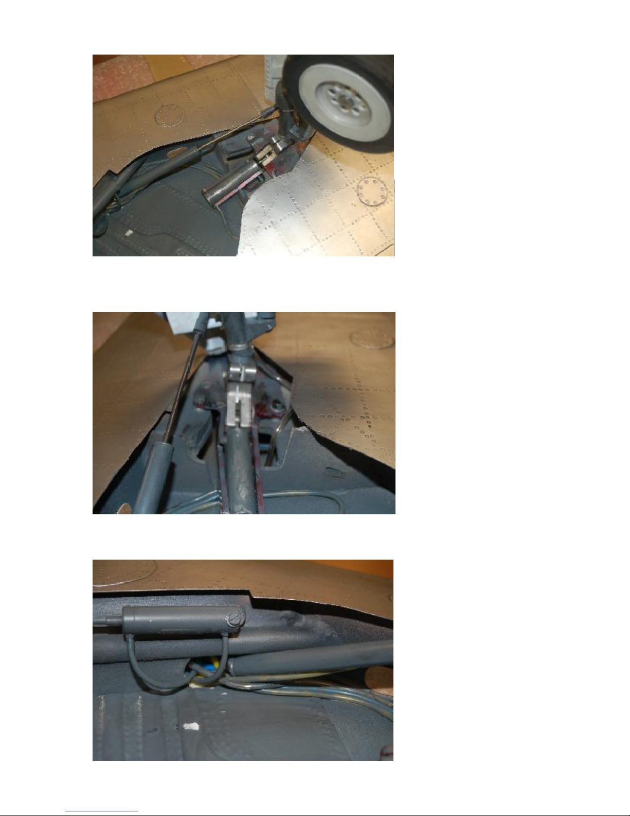
The supportar cylinder is not
only adummy for the
characteristical scalelook, it is
s real active cylinder whichis
neededto safly opperate the
landing gear as the strut and
wheel are quiteheavy for the
smal sylinderof the retract unit
itself.
It is absolutly nessecaryto
installthis active support
cylinder.
First, takeoff the main gear
door again,that you see where
you are working.
Mount the “piston end” of the
cylinder to the strut. Tapthe
M3 thread in and usean
M3x12 mm allen screwto bolt
throughthe ball link.
Retract the gearand locate the
mounting point of the other end
of thecylinder.It is
Once you have found the
position, move the gearup and
down, to see if the positions
are right.Youmight have to
changethe position of the
bottom mount slightly.After all
is confirmed andmoves
smoothly,finally gluein the
monting.
Youwill not have to remove
thecylinder at the bottom
mount again, asyou can
disconnectthe cylinderfrom
the ball at the main strut, even
if you need to take out the
gear.
Page 42
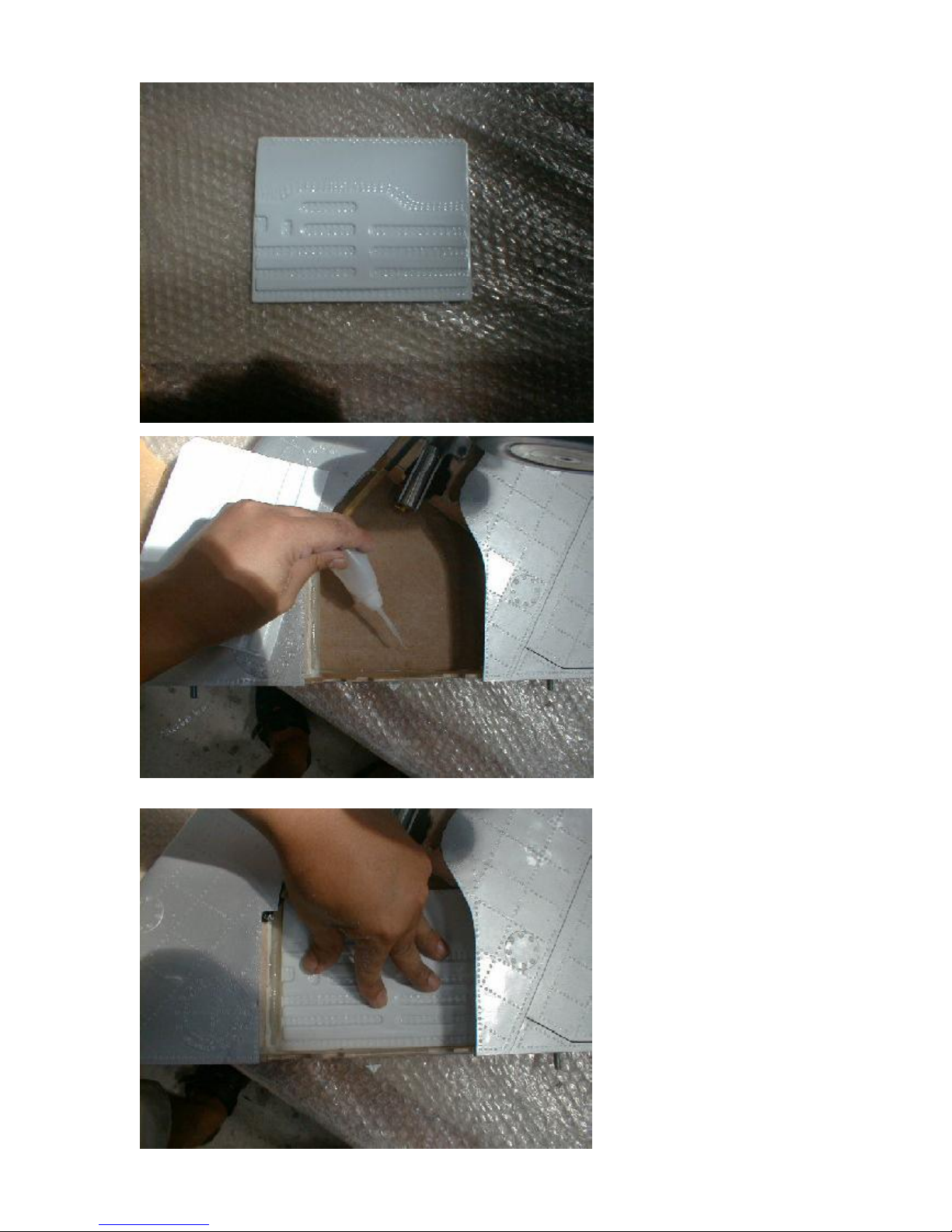
The inner gear wells usually
have a lot of structureinside.
We duplicated this for the
model airplaneas well.
Cut the styrene sheet according to the shape of the gear
box, andglue it in withCA
glue. Dont usetoo much , as
the CA might wrinkle the top
surface of the wing, if it gets
hotduring curing.
Page 43
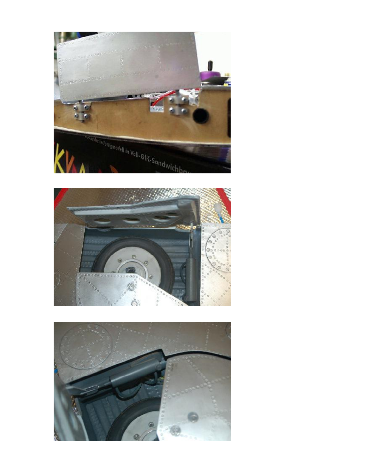
Now, weare installing the gear
doors.The hinges are
mounted to the outside of the
root rib.Therefore the half
roundcutouts must be filled
withplywood.
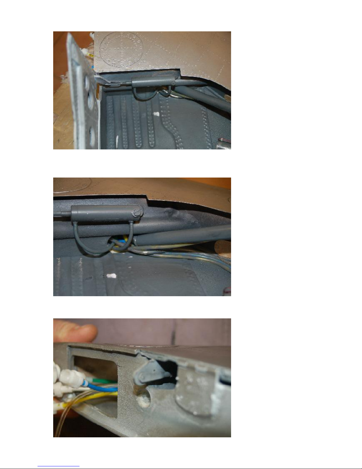
The cylinder is mountedto the
front spar, just in topof the
wingtube sleeve. thecontrol
horn is placed at the very front
end of the gear door, so the
root rib must be cut out in this
area.
The Robart #165 cylinder is
mounted with an M3 Screw to
the plywoodsupport wichgets
glued to the spar in the correct
positionso completely open
and closethe gear door.
Page 44
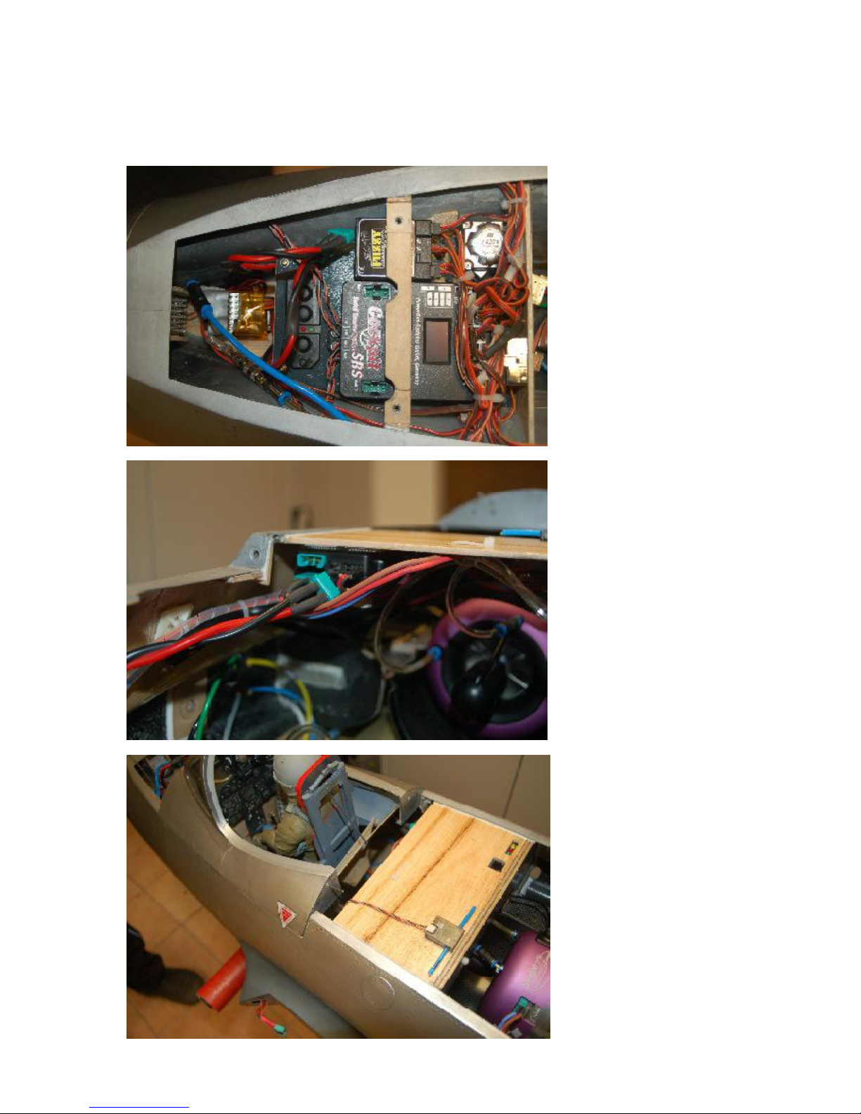
Note that the control horn
sticks out of the root rip toward
the fuselage when the gear
door is closed. Make sureto
gernerateenough clearancein
the root rib andalso you will
have to grinda hole in the root
rib on the fuselage to allowthe
control horn to stick in when
the wingis mounted to the
fuselage.
Page 45
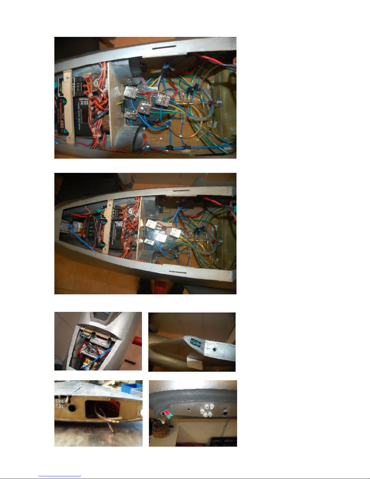
Here are some ideas, howto
fit the electronichardwareinto
your plane. As this planeis
not a beginners project, we
must leave it up to you, to
install all thecomponents you
are going to use. We gave
you servo specs,
recommendedengines, fuel
cells, and more, at different
sectionsof this instruction
manual already.At theend all
is your decision, based on all
yourexperience and
preferences.
11. Ideas for Elecronic &
hardware installation
Page 46
Page 47
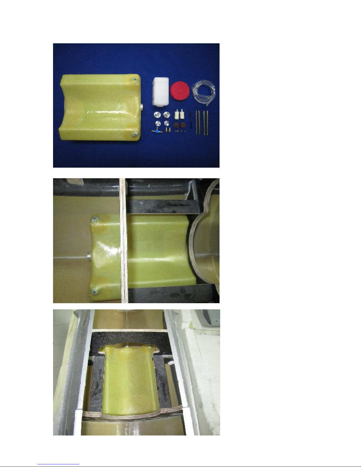
12. Optional fuel tank installation
The Fuel Tank for the Mig-15 is
available throughCARF asan
accessory item whci we highly
recommend to use.
With avolume of almost 4
liters it is a ferfect size Tank for
longflight times.
It comeswith plumbing
accessories, clunk and even a
hopper tank.
It is designdto be positioned
right in the CG so that there is
no efect on the CG of the
plane once the fuel gets
burnedthroughoutthe flight.
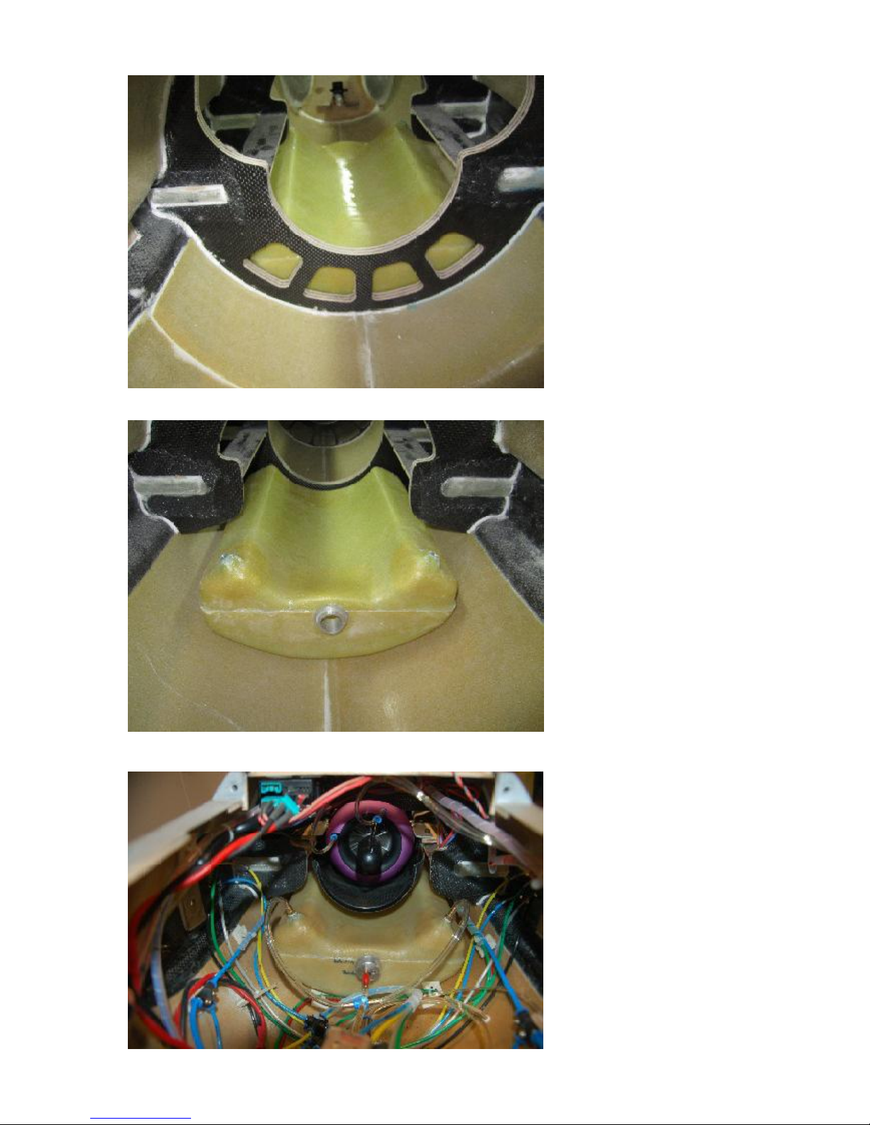
TheTank will be mountedright
underthe engine ducting ans
schonin the following pictures.
The clunk goesin from the
center andthe 2 vents are in
the front top right cornerof the
tank.
It is important to usethe TFitting for the 2 entsand bring
them togetherinto one single
overflow. Do notleave the
ventsseparate!
Page 48
Page 49

13. control throws & CG setting
Elevator: UP 20 mm (1”)
DOWN 18 mm (1”)
Rudder: RIGHT/LEFT 50 mm (2”)
Aileron UP 25 mm (1”)
DOWN 20 mm (3/4”)
Flaps TAKEOFF 25 mm (1”)
LANDING 80 mm (3 1/4”)
Speedbrakes LANDING max. travel
The CG is 50 mm
in front of the
rear wing spar
Useful tips for flying
Speedbrakesare very efficient, flaps too, but the plane tends to bounce at touchdown. If a little head wind,
try to useonly speedbrakes andflapsin takeoff position. With flaps and speedbrakesfully extendedthe
plane can fly incredibly slow.Don’t forget that, whenyou are in the final approach.If you can fly it slow
enough,the plane landsperfectly even withflapsfully down. But, it will be slowerthan you would EVER
think.
Ailerons are very soft. Perfect for scaleflying. Donot try toincrease theaileronthrow,it will kill the overall
scale appearance. You might want to think about using a gyro even onthe ailerons. It smoothensthe flying
even more, andthe MiG15 appearsto be on rails, even in windyconditions.
The rudder should definitely usea gyro. It improves the groundhandling characteristics, and it makes the
plane tracking just perfectly under crosswind conditions.Put the gyro onboth steering nosewheel and
rudder. Be careful with the setting, the rudder isvery sensitive, and youshould betterreduce the sesitivity
to no more than 25-30%.
Take offs: The full scale MiG-15 is known for very low climb rate at takeoff, same asthe F-86 Sabre and
other jets of that age. The MiG doesit perfectly.Take off with 1/3 throttle, and the plane gets off the ground
like a glider. Let it go a few feet high, switch the gear, andclimb slowlyinto the first turn.
Landings:As said before, the MiG-15 isa very slowlanding airplane. It floats forever, nothingcan kill the
lift. And when you think, it’s falling out of the air, then you can still make it slower. It amazed usas well, but
theseflying characteristicsare dueto the very low wing loading.A plane with that impressive size and that
low weight is capableof manouvers, whereothers would fail. Of course,bumpy wind is notit’sbest friend.
But thereforeyou have the gyros, andthey will doit all.
Have greatfun with thatgreat airplane.
Your CARFModels Team
For questions contactyour sales rep or email: [email protected]
Page 50
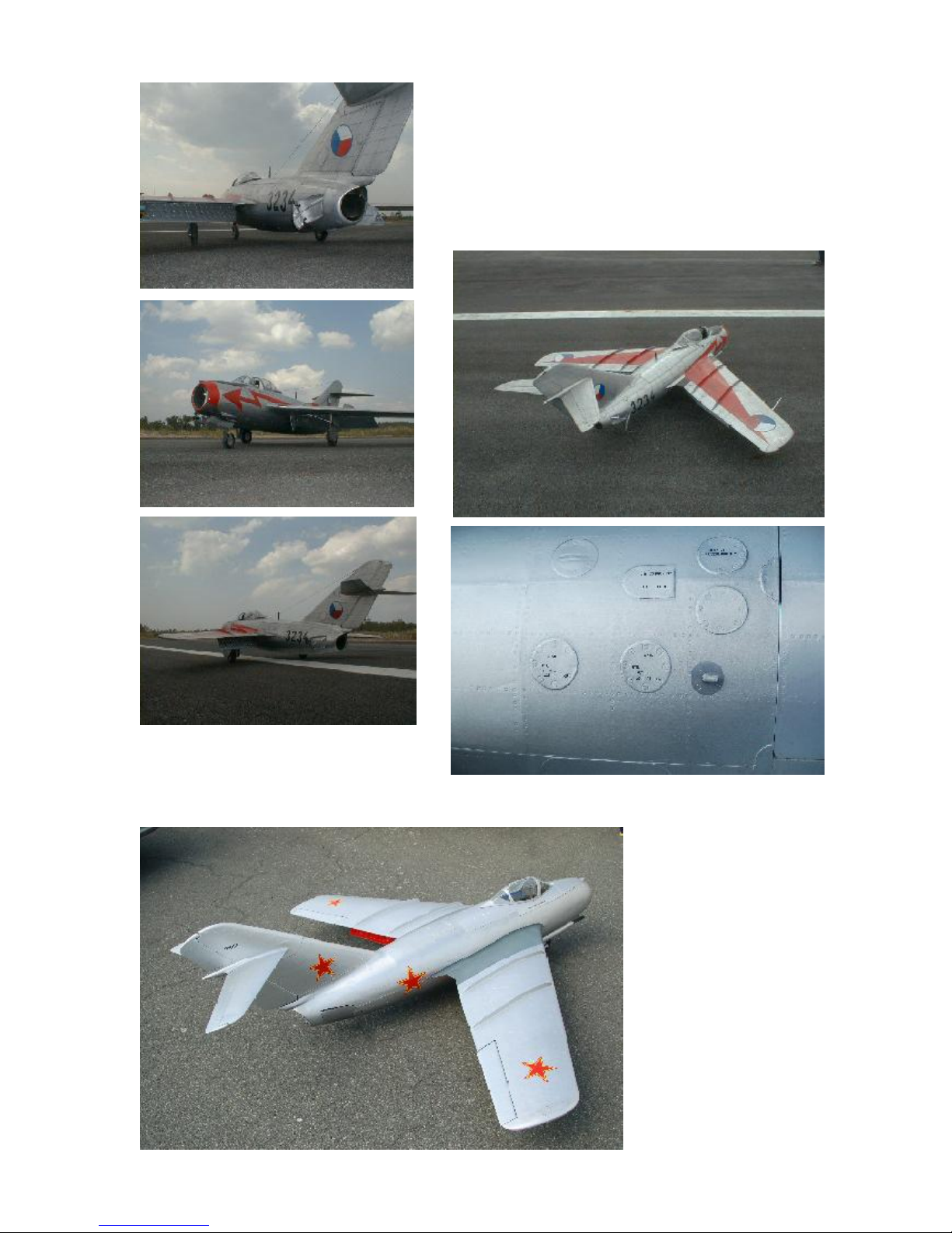
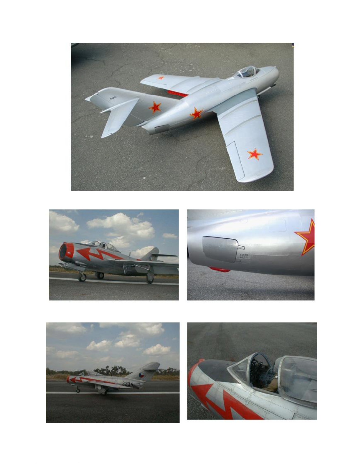
If your plane at the very
end looks as impressive as
these, you did a good job...
Page 51
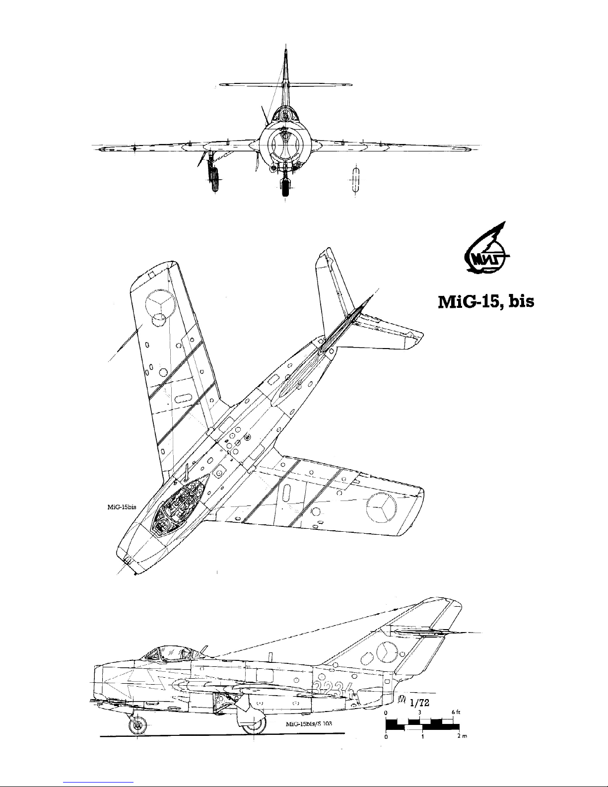
scale drawing 3-view
Page 52
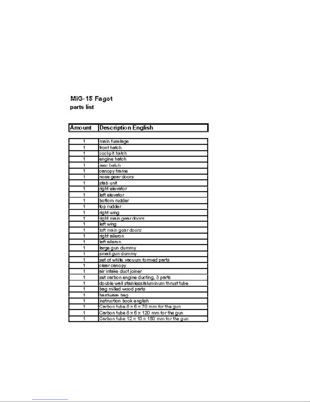
14. Appendix
Kit Contents:
Page 53
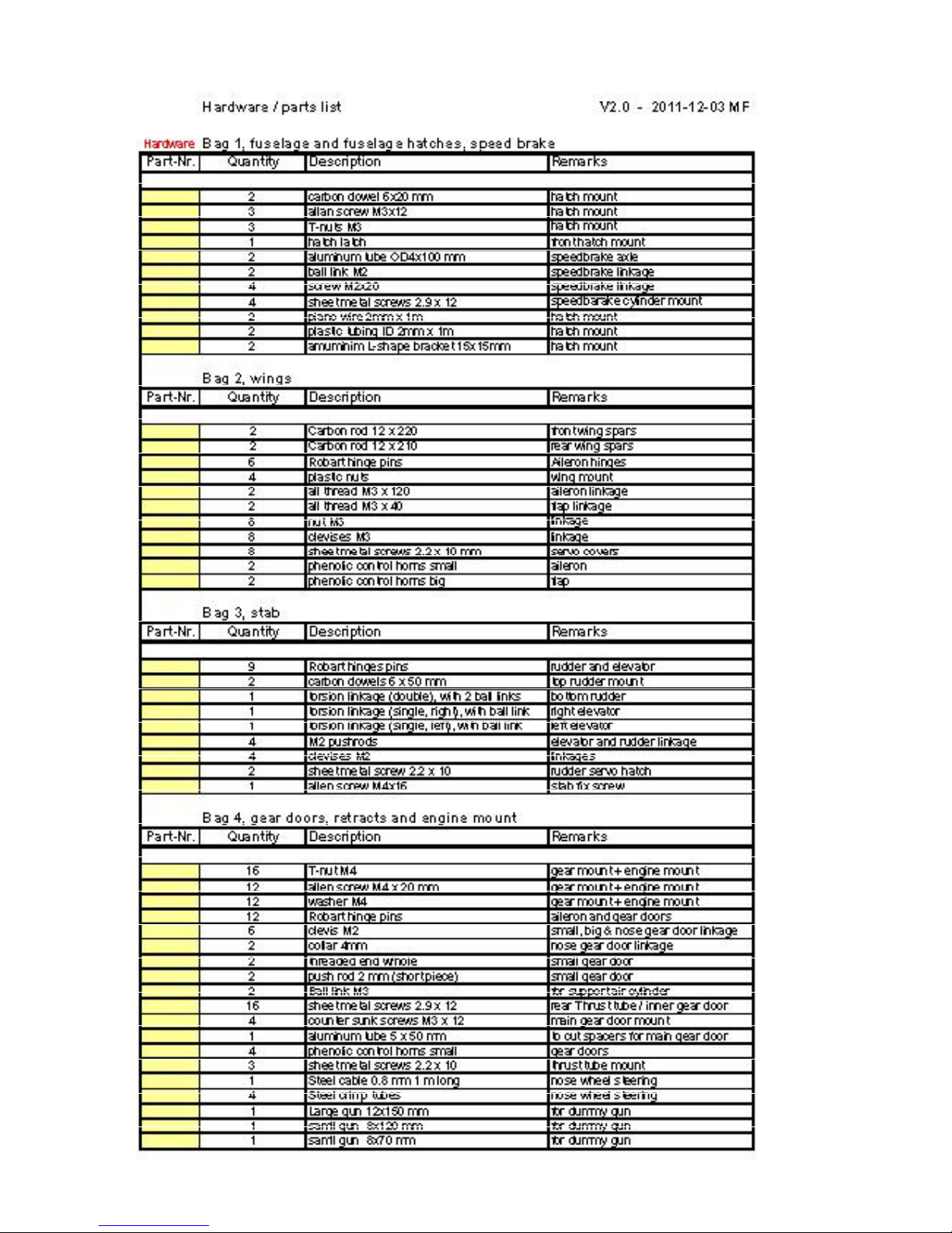
 Loading...