

Page 1
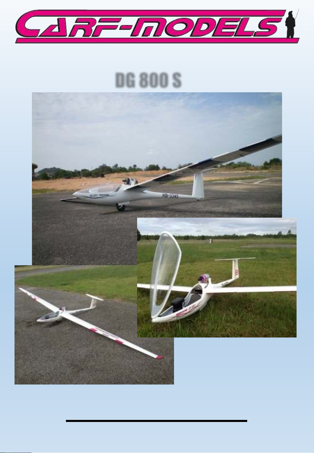
DG 800 S
Instruction Manual
F. W. 28 /7 /2 01 4
Vers. 1.0
Page 2

Thank you very much for purchasing the CARF Models DG-800S high performance
glider. Before you get started building and setting-up your new aircraft, please
make sure you have read this instruction manual, and understood it. If you have
any questions, please don’t hesitate to contact your Rep, or CARF-Models directly.
Below are the contact details:
Email: [email protected]
Or call your CARF Rep by phone!!! He will be there for you. Please write down
his phone number somewhere on this manual, you’ll find it, after you’re
logged in on our website, on the top right corner of every page.
Liability Exclusion and Damages
You have acquired a kit, which can be assembled into a fully working R/C model
when fitted out with suitable accessories, as described in the instruction manual
with the kit.
However, as manufacturers, we at CARF-Models are not in a position to influence
the way you build and operate your model, and we have no control over the
methods you use to install, operate and maintain the radio control system
components. For this reason we are obliged to deny all liability for loss, damage or
costs which are incurred due to the incompetent or incorrect application and
operation of our products, or which are connected with such operation in any way.
Unless otherwise prescribed by binding law, the obligation of the CARF-Models
company to pay compensation is excluded, regardless of the legal argument
employed.
This applies to personal injury, death, damage to buildings, loss of turnover and
business, interruption of business or other direct and indirect consequent damages.
In all circumstances our total liability is limited to the amount which you actually
paid for this model.
BY OPERATING THIS MODEL YOU ASSUME FULL RESPONSIBILITY FOR YOUR
ACTIONS.
It is important to understand that CARF-Models Ltd, is unable to monitor whether
you follow the instructions contained in this instruction manual regarding the
construction, operation and maintenance of the aircraft, nor whether you install
and use the radio control system correctly. For this reason we at CARF are unable to
guarantee, or provide, a contractual agreement with any individual or company that
the model you have made will function correctly and safely. You, as operator of the
model, must rely upon your own expertise and judgement in acquiring and
operating this model.
Page 3

Important/General Notes
Elastic Hinges:
The ailerons, flaps and elevator are all hinged already for you - laminated in the
mould and attached with a special nylon hinge-cloth, sandwiched between the
outer skin and the foam. This nylon hinge is 100% safe and durable. You will never
have to worry about breaking it, or wearing it out. There is no gap at all on the
top side of the surface, and there is a narrow slot in the bottom surface, where
the control surface slides under the skin during ‘down’ throw. This means that the
hinge axis line is on the top surface of the wing and stab, not in the centre.
The slot seal needs some explanation, too. The bottom side of every control
surface is sealed with the same type of sealing tape the full scale aircraft is
sealed with. It is a sandwich of several special tape layers, one being a specially
pre-curved mylar sheet. Take care of this tape as it is very important for the
proper function and the designed efficiency of all control surfaces.
Servo Choice:
We strongly advise that you use the recommended high-torque digital metalgeared servos on all the main flight controls, and the milled plywood mounts are
specifically designed for these.
There are plenty of alternative servos available from many manufacturers.
However, it is important that you measure the “hight” of the servo from the
mounting flanges to the control arm. This dimension is important to know BEFORE
you glue any mounting frames in the stab or wing.
Servo Screws:
Fix the all the servos into the milled plywood servo mounts using the 2.9 Ø
x13mm or 16mm sheet metal screws provided in the kit, not the standard screws
normally supplied with servos by the servo manufacturer. This is because all the
holes in our milled servo mounts are 2mm diameter, due to our CNC
manufacturing process, and this is too big for the normal screws.
Building Sequence:
The actual building sequence is your choice, but it is definitely most efficient to
follow the sequence of this manual.
Page 4

Tak e Car e:
Composite sandwich parts are extremely strong, but fragile at the same time.
Always keep in mind that these composite airplanes are designed for minimum
weight and maximum strength in flight. Please take care of it, especially during
transport, to make sure that none of the critical parts and linkages are damaged.
Always handle your airplane with great care, especially on the ground and during
transport, so you will have many hours of pleasure with it.
To p ro te c t t he f in ish e d su rf ace on t he ou t si de o f t h e mo de l f r om s cr atc h es a nd
dents during building, cover your work table with a piece of soft carpet, cloth or
bubble-plastic. The best way to stop small spots of glue getting stuck to the
outside painted surfaces is to give the whole model 2 good coats of clear car wax
first, but of course you must be sure to remove this 100% properly before adding
any additional paint, markings or trim.
Adhesives and Solvents:
Not all types of glues are suited to working with composite parts. Here is a
selection of what we normally use, and what we can truly recommend. Please don’t
use inferior quality glues - you will end up with an inferior quality plane, that is not
so strong or safe.
Composite models require good gluing techniques, due to the higher flying speeds,
and hence higher loads on many of the joints.
1. CA glue ‘Thin’ and ‘Thick’ types. We recommend ZAP, as this is very high
quality.
2. ZAP-O or Plasti-ZAP, odourless, or ZAP canopy glue 560 (for clear canopy)
3. 30 minute epoxy (stressed joints must be glued with at least 30 min & NOT 5
min epoxy).
4. Loctite Hysol 9462 or equivalent (optional, but highly recommended)
5. Epoxy laminating resin (12 - 24 hr cure) with hardener.
6. Milled glass fibre, for adding to slow epoxy for stronger joints.
7. Micro-balloons, for adding to slow epoxy for lightweight filling.
8. Thread-locking compound (Loctite 243, ZAP Z-42, or equivalent)
We take great care during production at the factory to ensure that all joints are
properly glued, but of course it is wise to check these yourself and re-glue any that
might just have been missed.
Page 5

When sanding areas on the inside of the composite sandwich parts to prepare the
surface for gluing something onto it, do NOT sand through the layer of
lightweight glasscloth on the inside foam sandwich. It is only necessary to rough
up the surface, with 80/120 grit, and wipe off any dust with acetone or denatured alcohol (or similar) before gluing to make a perfect joint. Of course, you
should always prepare both parts to be joined before gluing for the highest
quality joints. Don’t use Acetone for cleaning external, painted, surfaces as you
will damage the paint.
Tip: For cleaning small (uncured) glue spots or marks off the painted surfaces you
can use old-fashioned liquid cigarette-lighter fuel, like ‘Ronsonol’ or equivalent.
This does not damage the paint, as Acetone and many other solvents will, and
this is what we use at the factory.
At CARF-Models we try our best to offer you a high quality kit, with outstanding
value-for-money, and as complete as possible. However, if you feel that some
additional or different hardware should be included, please feel free to let us
know. Email us: [email protected]. We know that even good things can
be made better !
Did you read the hints and warnings above and the instructions carefully?
Did you understand everything in this manual completely? Then, and only
then, let’s start assembling your CARF-Models DG-800S. If not, please read it
again before you continue.
Equipment:
This is a list of suggestions for equipment to be installed in your DG-800S:
1. 2 16mm aileron servos like Graupner DES 678 or JR 3711 HV
2. Or: 2 20mm aileron servos like Graupner DES 707 or JR DS 8411 HV
3. 8 20mm standard size servos with at least 15 kg/cm or 120 oz/in like the above
4. Powerbox Sensor oder Evolution or any other high quality power bus
5. Receiver batteries of appropriate size, depending on your planned flying time
6. Receiver with at least 10 outlets
Page 6
General information
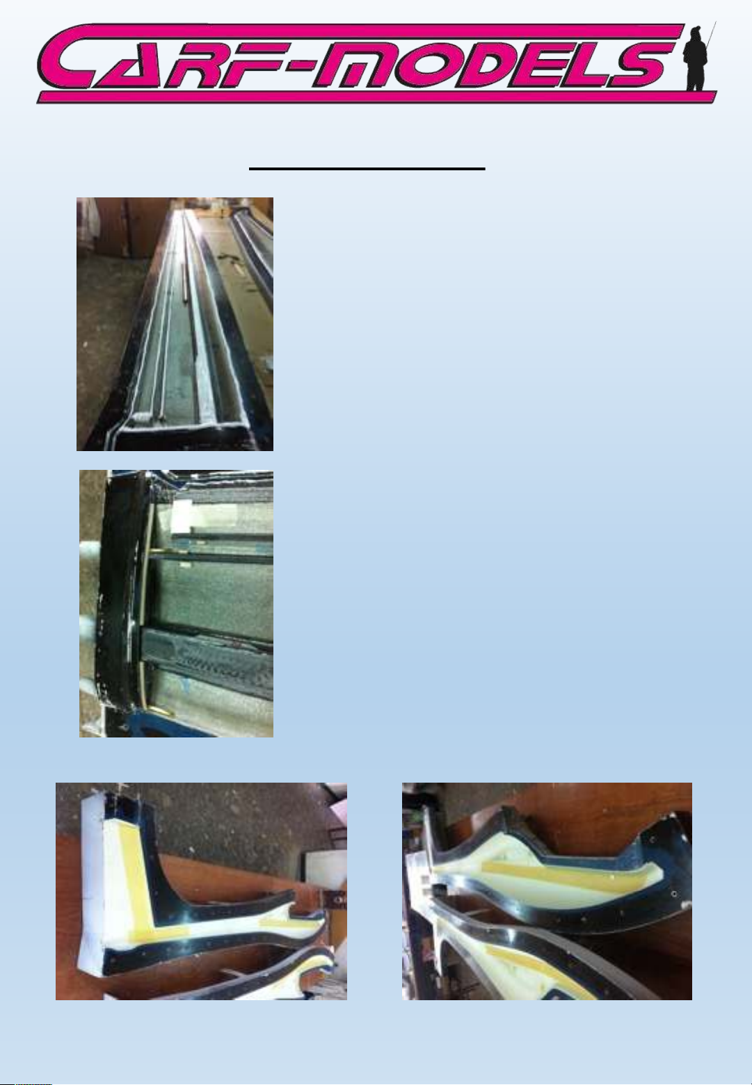
The wing of your CARF-Models DG-800S
is a so called all carbon wing. The skin
has several layers of carbon fibre as
well as the C-spars. These are laminated
in separate molds, all carbon, of course.
The fuselage is made from various glass
fibre layers, responsibly and well
engineered with Kevlar reinforcements
in the canopy and fin area.
This extensive use of high end materials
is unique in the industry and responsbile
for the incredible strength and overall
performance of the aircraft.
Page 7
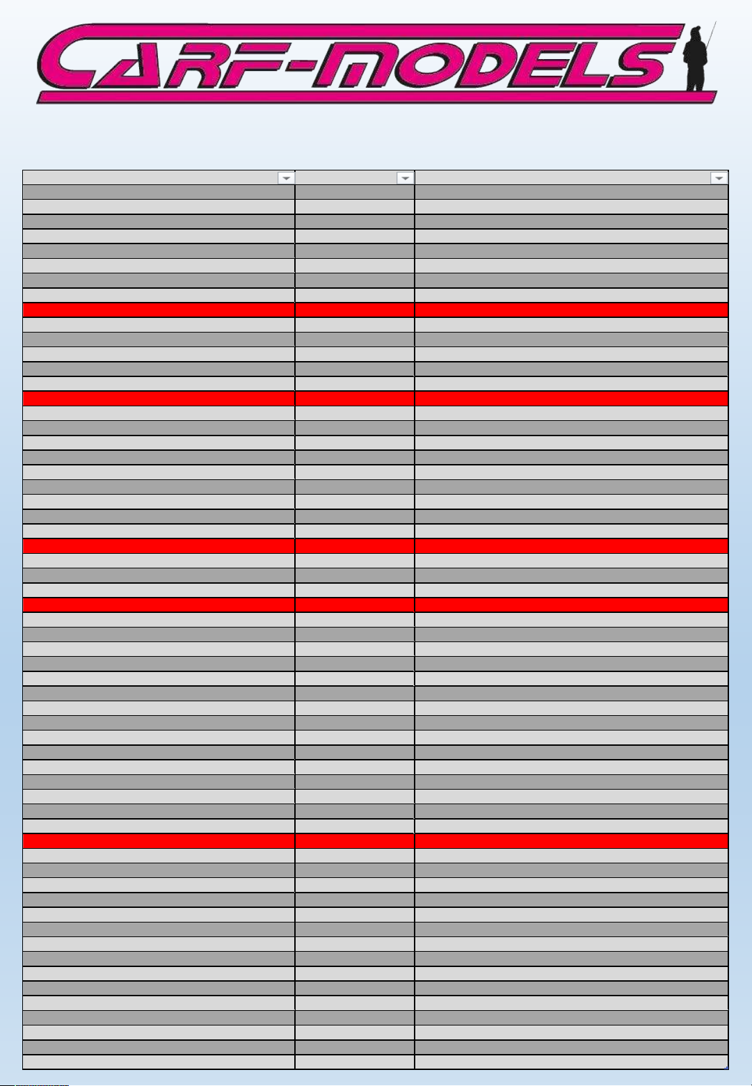
Liste Der Enthaltenen Bauteile
Material Name Piece For What
Threaded end M3 with hold for steel cabl
2 Ruder
PULL PULL WIRE DIA 0.8MM 2 x 2 Meter Ruder
CRIMP TUBES DIA 2MM 4 Ruder
Clevis M3 2 Ruder
ALLEN SCREW M 3*12 2 Ruder
WASHER M3 6 Ruder
SHEET METAL SCREW 2.9*13 4 Ruder
hinge wire 2mm 400mm 1 Ruder
Counter sunk M5x 60 2 Stab
Clevis M 3 2 Stab
ALL THREAD M3 x 20 mm 1 Stab
WASHER M3 4 Stab
SHEET METAL SCREW 2.9*13 4 Stab
ALLEN SCREW M 3*16 4 Gear
ALLEN SCREW M 4*10 2 Gear
WASHER M3 8 Gear
WASHER M4 2 Gear
ALL THREAD M3 x 50 mm 1 Gear
Clevis
M3 2 Gear
Nut M3 2 Gear
hinge wire 2mm 400mm 2 Gear
SHEET METAL SCREW 2.9*13 4 Gear
SHEET METAL SCREW 2.9*13 4 Towing Clutch
ALLEN SCREW M3*12 2 Towing Clutch
WASHER M3 6 Towing Clutch
ALL THREAD M3 x 20 mm 2 Wing
ALL THREAD M3 x 30 mm 2 Wing
THREADED PUSHROD M2*200 2 Wing
Clevis M2 2 Wing
Nut M2 2 Wing
Celvis M 3 8 Wing
Swasher M3 4 for 20 mm Aileron Servo
ALLEN SCREW M3*12 4 for 20 mm Aileron Servo
T Nut M3 4 for 20 mm Aileron Servo
Nut M
3 8 Wing
SHEET METAL SCREW 2.9*13 24 Wing
SHEET METAL SCREW 2.2*10 24 Wing
WASHER M3 32 Wing
ALLEN SCREW M 6*30 2 Wing
Khurled plastic nut M6 2 Wing
Servo mount Ruder 1 3 mm Plywood
Servo Mount Retract 1 3mm Plywood
Servo mount Towing Clutch 1 3 mm Plywood
Plywood medium 3 mm 1 11 x 7 cm Support Powerbox
Plywood medium 3 mm 2 3.5 x 100 Support Batterie
Retract Look 2 x 6 mm Medium Plywood
2 Rear and Front
Aluminium Bracket for 20 mm Servo 2 Aileron
Light plywood frame for 20mm Servo 2 Aileron
Switch Support 1 Powerbox switch
M 3 x 35 mm 1 Tail Wheel
Velcro 1 30 cm
Servo Hatch smal white 2 16 mm Aileron Servo
Servo support 2 16 mm Aileron Servo
Steel wire 1.2 mm 30cm 1 Towing Clutch
Plastic Tube red 30cm 1 Towing Clutch
Page 8
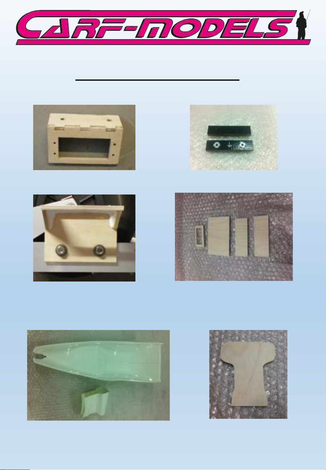
milled wood parts and hardware
Rudder servo tray
Retract Servo tray milled parts for RC equipment
Retract mounts
Cockpit tub and parts
Milled instrument panel
Page 9
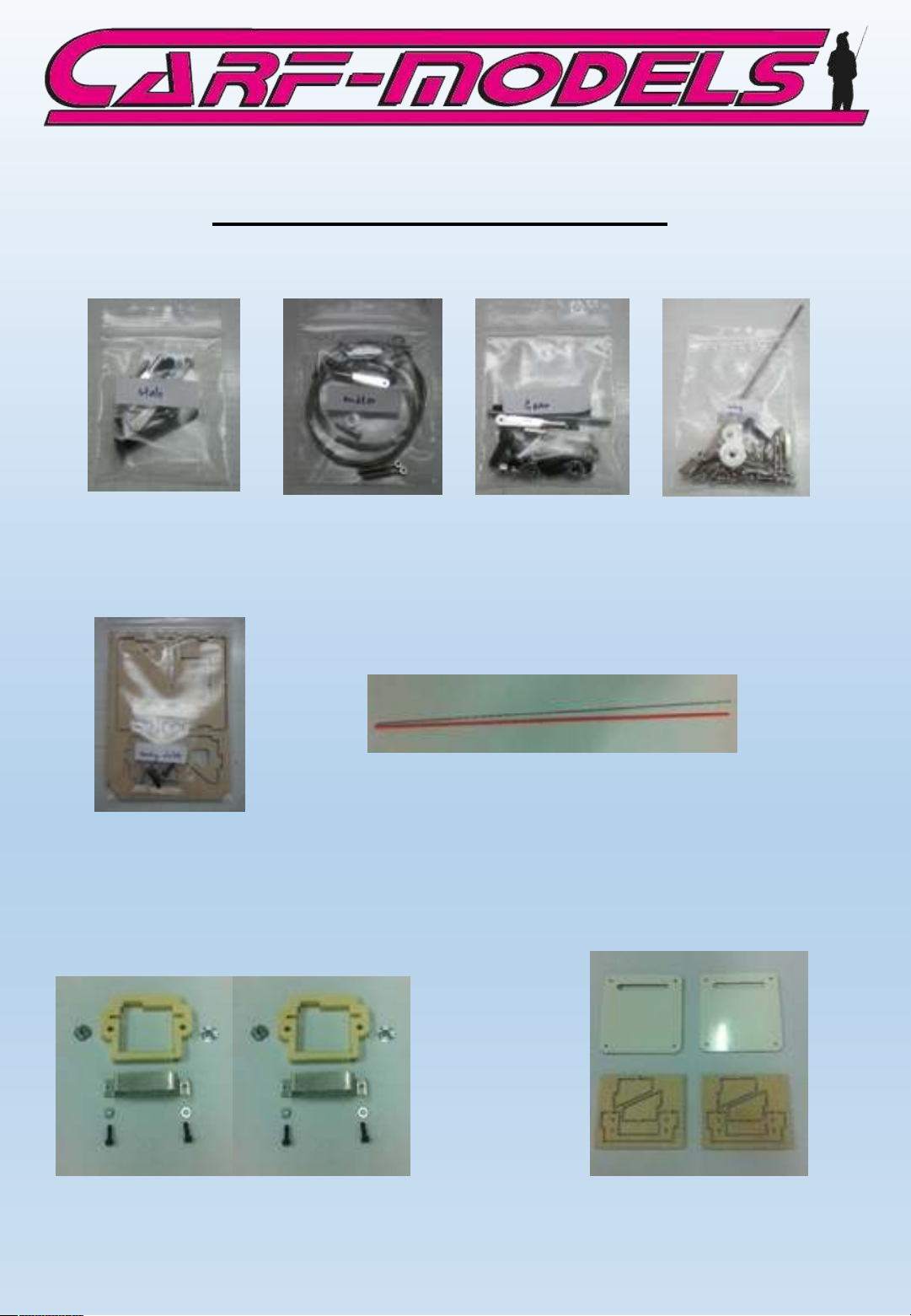
Milled wood parts and hardware
Horizotal Stab Rudder
To w re le a se
Retract
Wing
20mm (standard size)
servo mount parts
16 mm (mini size) servo
mount parts
Page 10
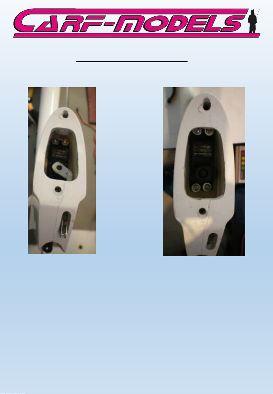
Horizonal stab installation
Install a standard size high quality elevator servo with the included 2.9 x 13
mm self tapping screws. Use washers if necessary.
The elevator linkage is assembled from the 20 mm M3 all thread and 2
spring steel clevises.
NOTE: Since space is very tight, these clevises must be secured with
LOCTITE after the final elevator setting is adjusted.
Page 11
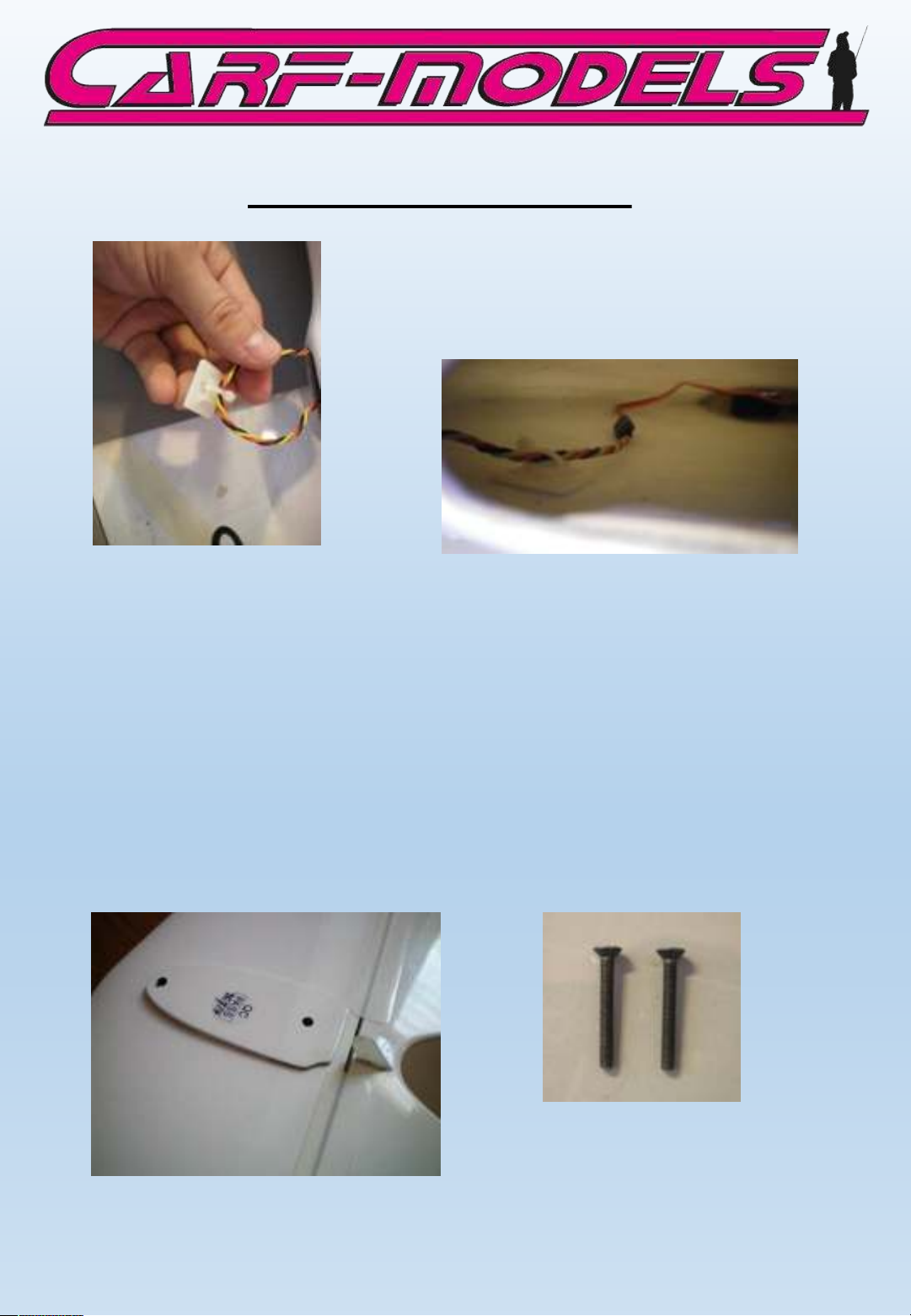
Horizontal stab installation
Extend the servo wire, either by soldering an
extension or connecting a pigtail socket. Secure
the extension so that it cannot disconnect under
any circumstances.
It is helpful to use the tailwheel opening to feed
the wire forward. Use cable sockets to secure it
to the fuselage wall.
Make sure that it is not rubbing against retract
and carbon formers.
The horizontal stab is readily built and can bolted on immediately with
the included M5 x 40 mm counter sunk bolts.
Page 12
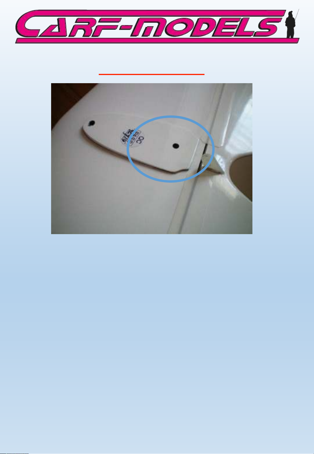
RECENT UPDATE!
Note: During countless test flights it has been noticed that the stab
incidence should be reduced by 0.7 degree in order to maximize
the performance of our DG-800. Even though the plane is flying
very well with the incidence out of the box in slower thermal
flying, the faster you want to fly, the more you feel you need to
trim down elevator.
Please sand or grind the spacer highlighted on the photo down to
zero thickness at the rear. This will reduce the incidence of the
stab just the right amount to allow extremely fast flying at fully
neutral elevator.
The result is that you can move the CG approx. 10-15 mm back by
removing approx. 400 gram of weight out of the nose.
New kits should have the spacer already sanded down in the
factory. Such stabs are marked with a RED DOT on that very spacer
to avoid any misunderstandings.
Page 13
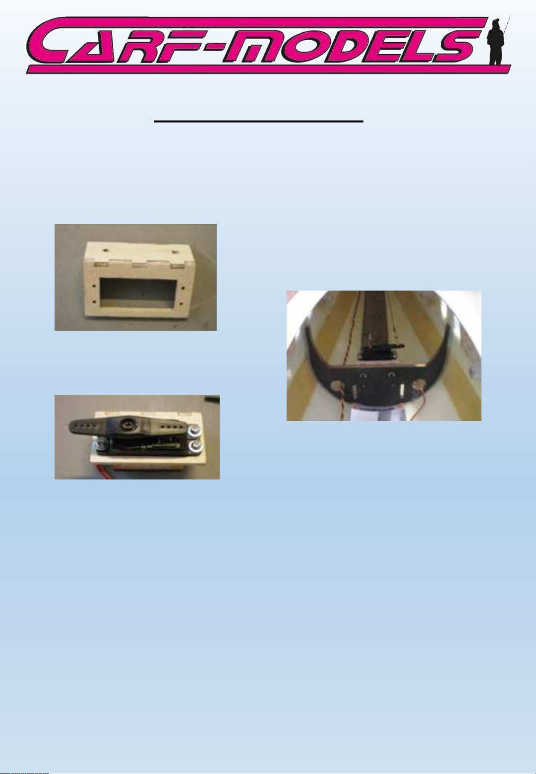
Rudder servo installation
The rudder servo tray is already assembled and holes for the servo
are drilled. Use 2.9 x 13 mm self tapping screws and washers to
install your standard size servo (preferrably of the same type as
the elevator servo)
Then bolt the servo tray from the rear against the landing gear
former.
NOTE: Use Loctite to secure the bolts!
Page 14
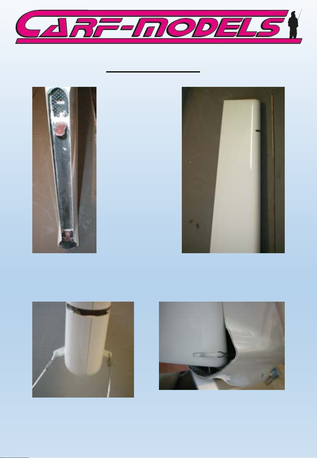
Rudder installation
The spar with the hinge posts is already installed and glued
securely. Also the rudder has the hinge pin sleeves and the cutouts preinstalled. It can be attached to the fin immediately.
Attach the steel wires by looping them through the control horns and
crimp them with the included crimp sleeves.
NOTE: Take great care when crimping, use double loops to be sure!
Page 15
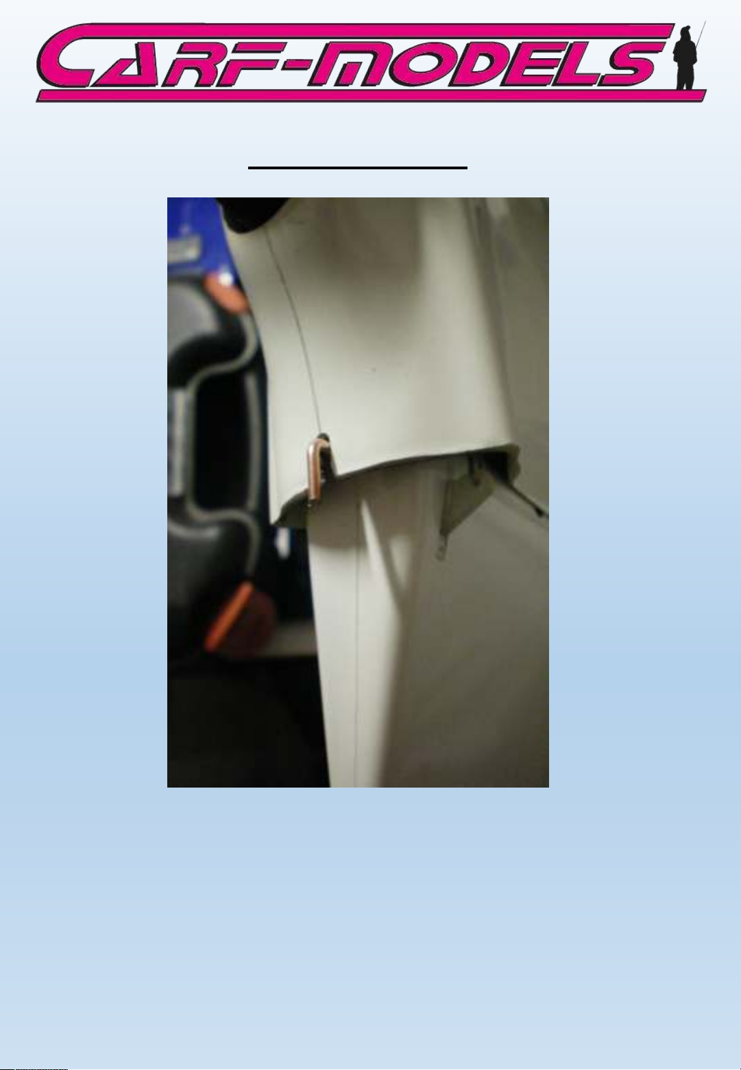
Rudder installation
Trial fit the hinge pin, either conventionally from the top (where
you can always see it) or from the bottom, like shown in the
photo. In that case it is important to secure the pin against
accidental loss. Bend the end approx. 10-12 mm (1/2”)
Page 16
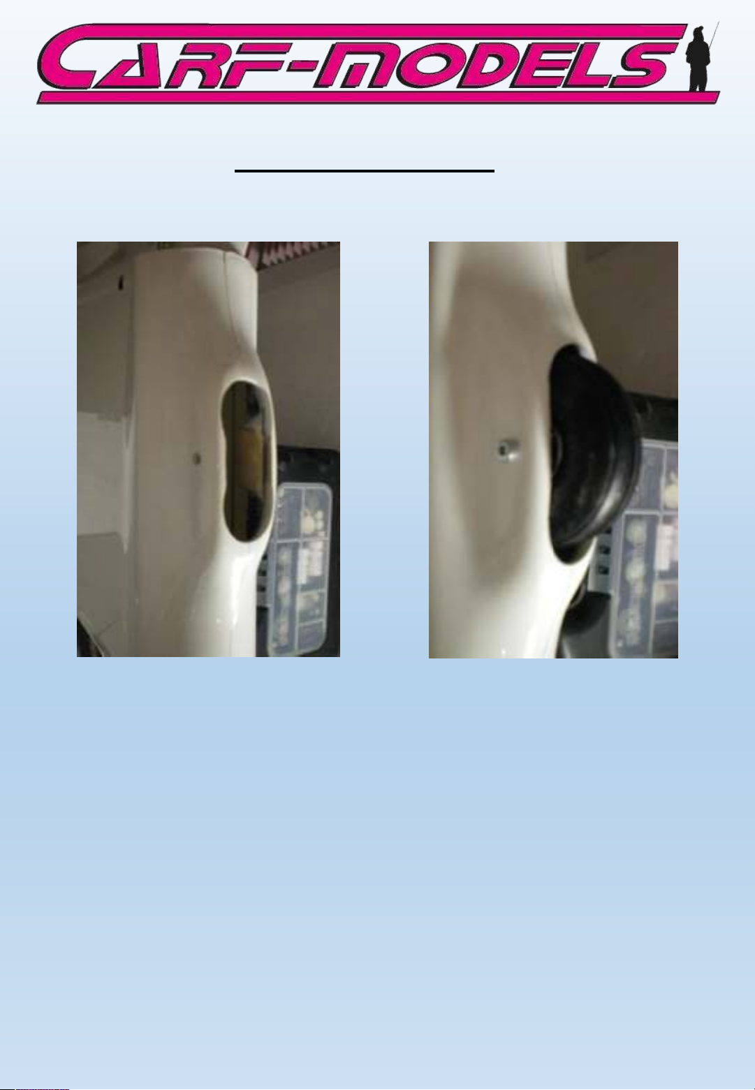
Tai l Wh ee l In st al la ti on
The tail wheel axle can be made from either M3 or M4 bolt, 35 mm
long, depending on the wheel used. The predrilled hole might
have to be adjusted slightly to fit.
Page 17
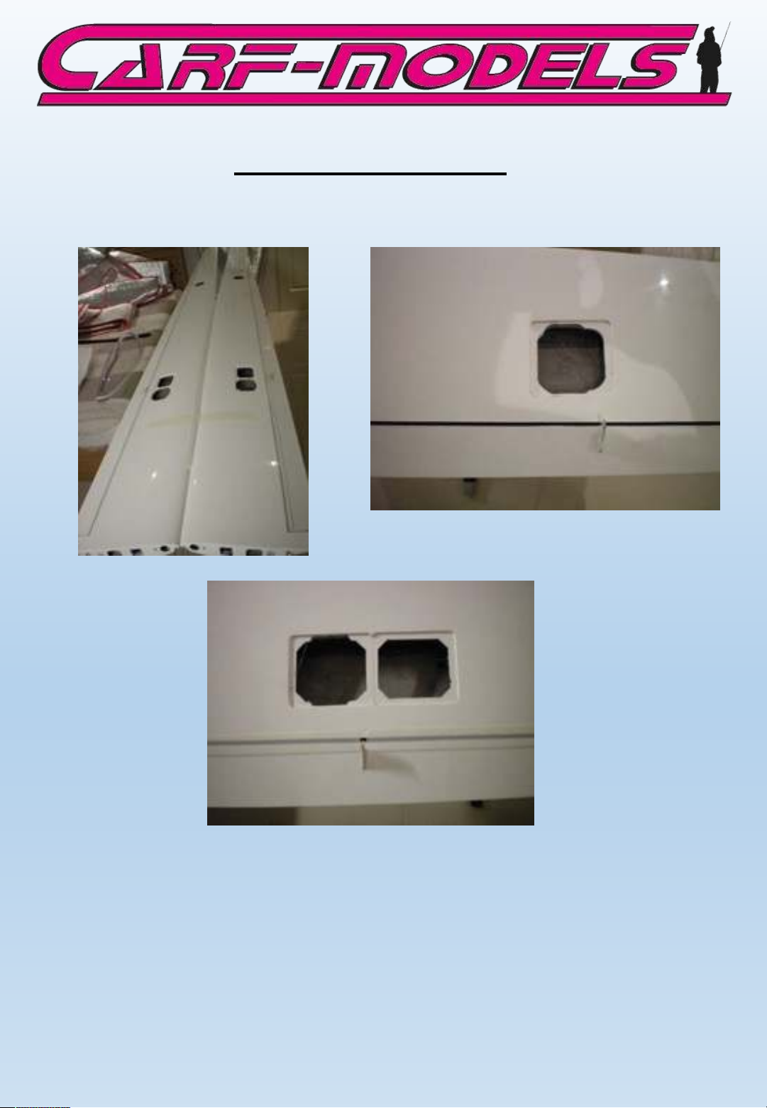
Wing Servo Installation
The wings are completely finished. The slot cover tape is
attached, control horns are installed and the speed brake cover is
precisely attached.
Page 18
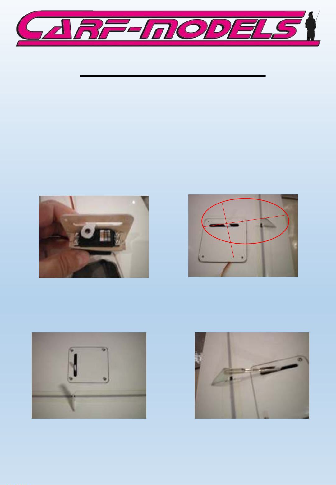
Installation of 16mm Aileron Servos
Important Note:
A 16mm Servo can be used if it is one of the newest high end servos with
a torque of 10+ kg/cm. This is sufficient if not flown under extreme
conditions with oversized jet turbines.
It is recommended, however, to install a standard size servo, if the very
top performance and speed is desired. A special servo cover and mount
for standard size servos is optionally included in the kit!
For the installation of the aileron servos please use the 2.9 mm
sheet metal screws with washer once more. For symmetrical
travel please align the servo horn perpendicular to the linkage!
You mount the servo hatches with the 1.9 x 10 mm screws. Create
the linkage with a 20 mm long M3 all thread and turn on two
spring steel clevises. Use Loctite or CA glue (just like you did with
the elevator linkage) because there is no room for counter nuts.
Page 19

Installation of 20 mm standard size aileron servos
If you decided to use the standard size servos, you will use the flat
frame from 6mm plywood. Grind a recess for the servo horn as
shown on the photo. Then insert the M3 blind nuts and glue the
frame on to the skin.
Note: Sand the skin surface thoroughly with coarse sand paper and
use a little playdow (or similar) to fill the threads of the blind
nuts. Use a good 30 min epoxy or thickened laminating resin to
glue the frame in place. Trial fit with the servo to make sure it fits
the recess without binding and the servo horn aligns with the
control horn.
Once the frame is glued, fit the servo, use a dot of clear silicone
to help secure the servo in the frame (you will always be able to
remove the servo with moderate force). Then screw the metal
frame on with the M3 x 10 allen screws. Be very careful and use
washer if necessary so that the screws do not show through at the
outside of the top wing skin.
To mount the servo hatches use the 1.9 x 10 mm sheet metal
screws. The linkage is identical to the version with the 16mm
servos. Use Loctite or CA glue to secure the clevises on the
threaded rod.
Page 20
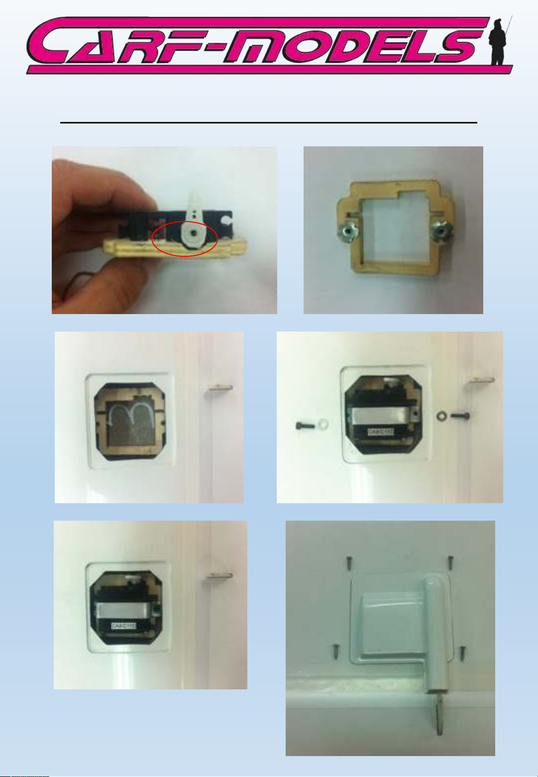
Installation of 20 mm standard size aileron servos
Page 21
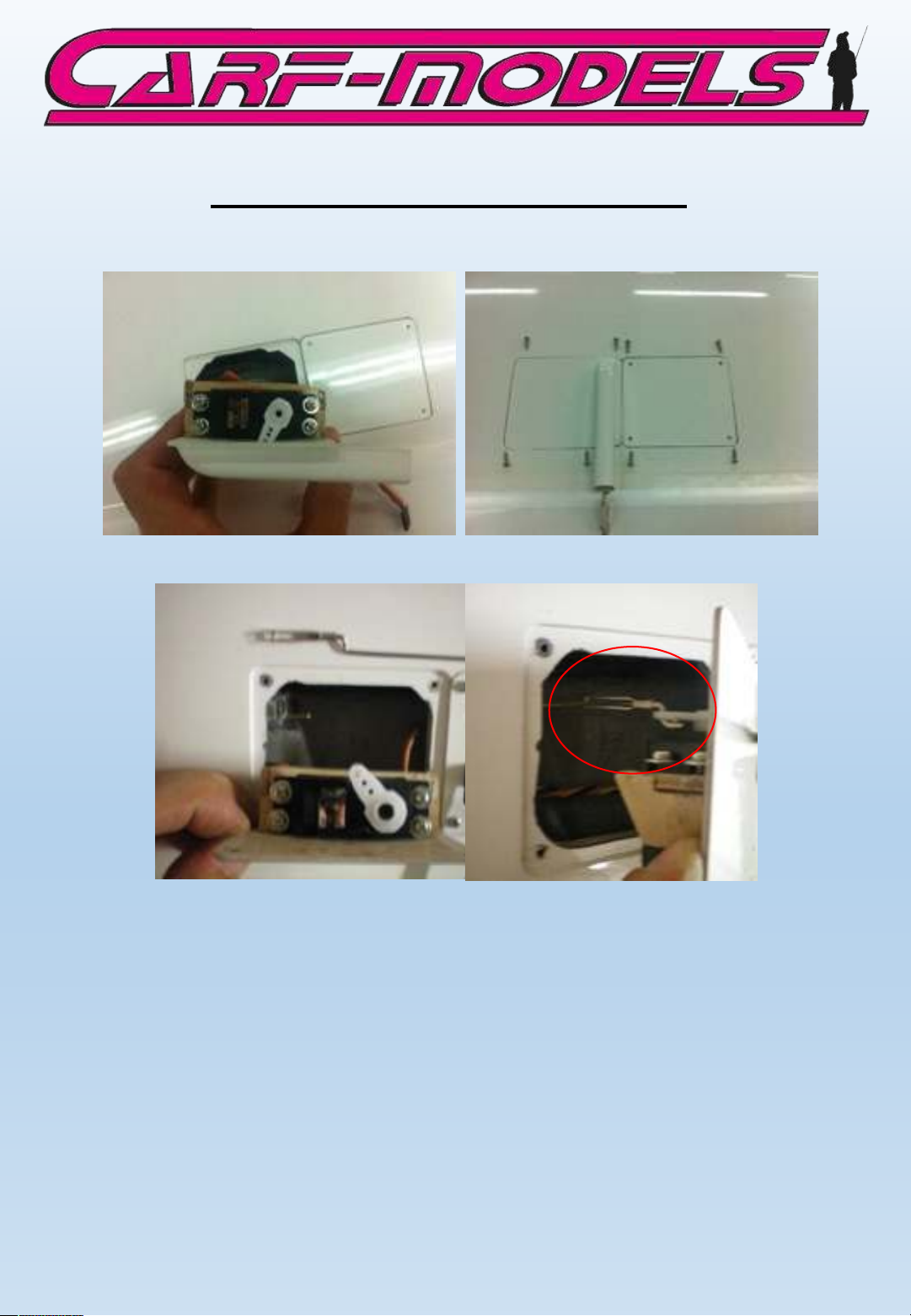
Spoiler and flap servo installation
The installation of Flap and Spoiler servos is identical to the
method of the 16mm airline servos. Use the 2.9 x 13 mm servo
screws included in the kit. Mount the hatches with the 1.9 x 10
mm sheet metal screws.
The flap linkage is built exactly like the aileron and elevator
linkage. For the spoiler linkage please use the 2mm threaded end
and one M2 spring steel clevis. The limited space requires a Zbend on the servo side. Do not experiment with this linkage. if this
linkage fails in flight it can have fatal consequences. If one spoiler
extends itself and the other one stays retracted there is almost no
chance to save your plane. That is because you most likely have no
idea what happened until you hit the ground…
Page 22
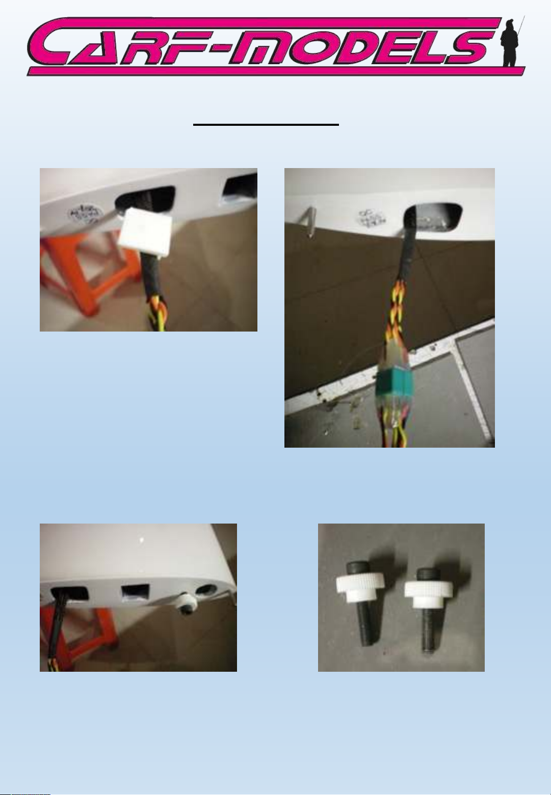
Wing attachment
For the wing servo wire
connection we recommend to use
larger connectors. You can glue 2
against each other. There are
many ways and preferences, you
might have your own style.
It is important that the wires
don’t rub against the edges of
the cut-outs.
The “floating spar” wing mount is completely finished. Install the
massive 30x30 mm carbon connector. Glue the knurled plastic nuts
on the M6 bolts and you won’t need any allen key to assemble
your plane at the field.
Page 23
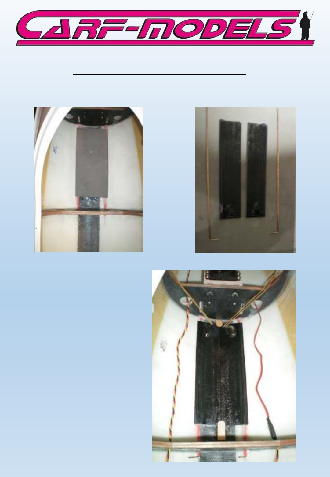
Gear door and retract installation
Create hinge pins from
the 2mm welding rod and
install the gear doors.
Glue stops from scrap
plywood and trial fit
hooks for two rubber
bands. Even though this
seems a very simple
method to keep the gear
doors closed, it is a very
efficient one. The
retractable gear is
designed to open the
doors against the spring
loading with the steel
loop in front of the
wheel.
Page 24
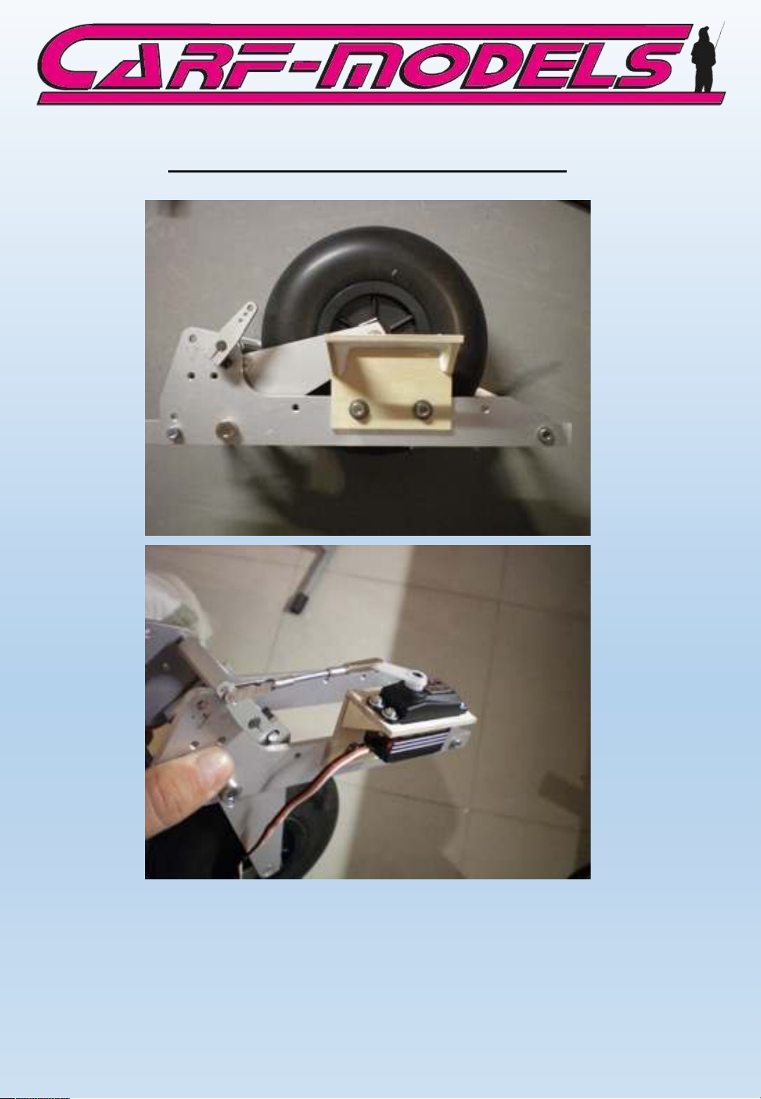
Gear door and retract installation
Mount the wooden servo mount with the M4 x 12 allen bolts to the
aluminum frame of the retract. As usual, use the 2.9 mm sheet
metal screws and washers to mount the servo in the frame. As
linkage use the M3 all thread and two spring steel clevises. You
might have to adjust the length of the linkage to work properly.
Note: Make sure the linkage is always 100% STRAIGHT!
Page 25

Gear door and retract installation
Slide the retract unit into the slots of the two formers and secure
it with the two wood boards, bolted on with each two of M3 x 16
allen bolts, as shown on the photos above.
Page 26
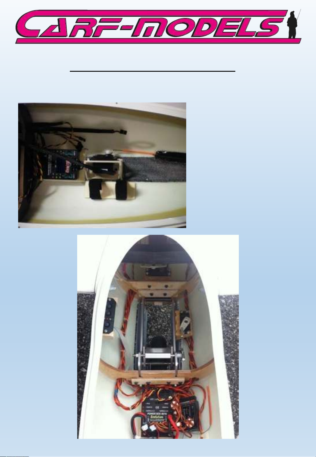
Remaining equipment installation
The front part of the
fuselage is used as
equipment bay. The photos
show only a sample
installation, since most
have their own ideas and
methods how to install
receiver, powerbox,
batteries, switches…. The
photos also show an easy
way to install the tow
release servo.
Page 27
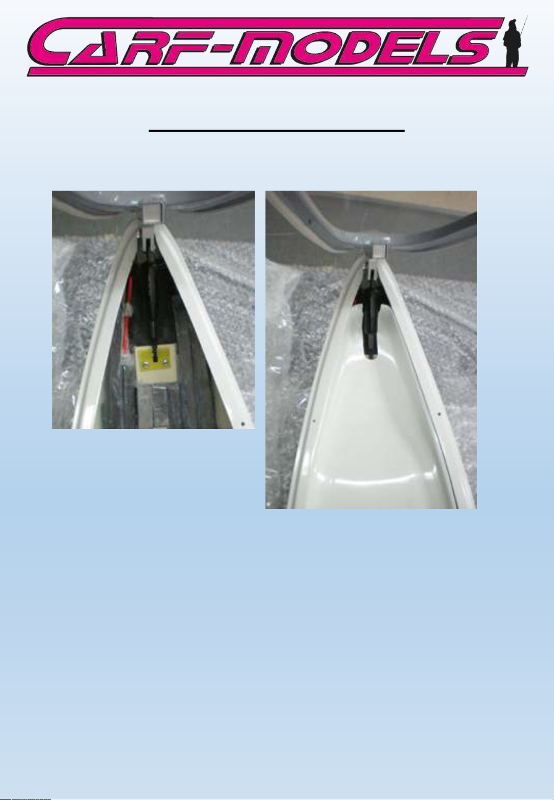
Canopy hinge and cockpit tub
The photo shows the gas spring mount of the canopy hinge,
which otherwise is already completely installed.
Up to 1.5 kg of lead must
be glued into the nose in
order to balance the
DG-800.
Make sure that the cockpit tub still fits the fuselage after you
installed all your equipment and balance weight. Cut a slot in the
rear part of the cockpit tub so that you can compress it sideways
to insert it under the lip of the fuselage. A scale seat cushion will
cover this slot and make it invisible.
The kit contains the base parts for an individual cockpit detailing
by yourself. However, we highly recommend to purchase the scale
cockpit available as an accessory. It saves you valuable working
hours which you better spend flying this magnificent airplane.
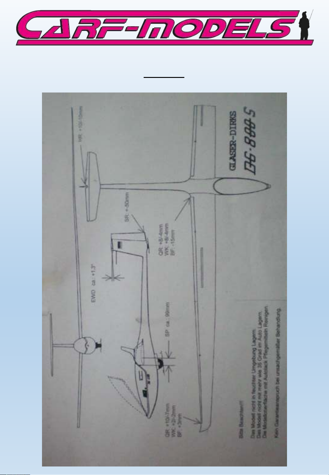
On the following page you will find the settings for control travel
and CG. Please note that with the reduced stab incidence you can
move the CG 10-15 mm back.
Page 28
Settings
 Loading...