

Page 1
Instruction Manual
Introduction:
Thanks for trusting us with your purchase of this latest top of the line Sport Jet from CARFModels. You will see, you have purchased an all composite, all carbon pane, very special, very
high end. A jet with a lot of new and unconventional construction techniques - which CARFModels has become known for and is proud of. Thus it is especially important to read this manual
a few times BEFORE starting the build and then follow it step by step.!
A few special features of our BOLT! will be highlighted here at the beginning of this manual:!
1. We tried to make things work without servo hatches. The cleaner the better, we say. So it
might be a little different to install most of the servos in your BOLT!, but it will be much less
work than you might initially think, if you have the right screws and the right tools. Therefore,
we have included in the kit the screws which work best for this purpose, and a specially
extended allen key, which makes servo installation a breeze. !
2. The CARF-Models BOLT! is consequently designed with full gear doors. It's a little more
complex, more sophisticated than without. Although some love the simplicity of not having to
deal with gear doors - the open wheel wells and nose gear cutouts will always be kind of
“rough”. So it depends on how the gear doors are designed, how successful and reliable their
operation will be. As a consequence we use magnetic help to keep the doors shut at highest
speeds, place gear door servos on strategic positions and supply linkages stiff enough to
safely do the task.!
3. We decisively opted for a fully ducted engine installation. Not so much of advantage for a
slower flying 3D jet, but absolutely crucial for a fast sport jet. The full ducting is going to
enhance the performance of the plane significantly. Again, a lot more work to do for the
manufacturer, and also considerable potential to do things wrong, but we’ve put a lot of effort
in calculating airflow based on the constant area rule, creating intakes with rounded lips, and
designing a carbon bypass which fits around the common 220-260 N engines like a glove.!
Page 2

4. The very special hatch design allows us to remove the entire nose of the airplane, shortening it
for transportation without having to spit the fuselage in half behind the engine. That way we
keep the closed ducting together and eliminate the additional weight of a joint behind the CG.
Just as much as we tried to avoid prominent servo hatches, we successfully avoided a large
engine hatch, too. Instead we designed a unique way of installing the engine permanently in
the carbon bypass and then inserting this complete assembly, including thrust tube, through
the back of the airplane. Once the complete system is installed, the engine is accessed,
removed and re-installed, through the removable bypass cover and through the top opening in
the fuselage, as narrow as it may seem. !
5. Last but not least, with clever weight distribution we were able to put the fuel exactly on the
CG, still keep the tail light, having lots of options to move heavy equipment in the very front of
the airplane, thus allowing a pretty long tail moment for a sport jet of this type. That gives you
the rock solid, locked in feel in the air, even at highest speeds. A full carbon fiber build, the
one-piece stab, the 30 mm (!) carbon fin tube and the 40mm carbon wing tube, together with
the carbon sheeted internal structural parts make the CARF-Models BOLT! stronger and stiffer
than any other jet, taking even the hardest abuse without wear, tear or failure. #
Now, admittedly, these are a few very special design features. But - let it sink in, try to understand
the philosophy behind it and enjoy the clean way of building a highly engineered and extremely
advanced sport jet. Boredom is not on the agenda when building a CARF-Models BOLT! Follow
this manual, do not change things, simply go with our advice and our recommended equipment
and accessories and you will have a blast building this airplane to the highest standards of what is
possible today. And the joy flying it will be endless.!
What you need to complete this build:
Listed CARF-Models BOLT! accessories:!
1) CARF/Electron BOLT! electric landing gear with wheels, brakes and GS-200 controller
2) CARF Kevlar saddle tanks
3) CARF Kevlar smoke tank
4) CARF double walled spiral reinforced stainless steel thrust tube
3rd party accessory recommendation:!
5) 7 pcs 20mm standard servos with approx. 25 kg torque (aileron, elevator, main gear doors and
nose gear steering, e.g. MacGregor 6928 HV or SAVOX 2071 HV))!
6) 3 pcs 20/21mm standard servos with approx. 35-40 kg torque (flaps and rudder, e.g.
MacGregor 8346 HV or SAVOX 2290 HV)!
7) 1 pc 15 mm mini servo with approx. 8-10 kg torque (nose gear door, e.g. MacGregor 2810HV
or SAVOX 1061)!
8) 11 metal servo arms 25 mm (1”)!
9) Cortex Pro or iGyro (this depends on your your preference and what radio system you’re going
to use)!
10) A Power distribution system like Powerbox Mercury, Professional, Jeti Centralbox 210/220!
11) A 220 - 260 N turbine engine (we use the KingTech 260 G2 but can recommend Frank Turbine
250, JetCat 220, 250, etc!
12) A set of high quality connectors for the joints between the main fuselage and nose cone,
wings, stab and fin. We strongly recommend to build your wiring harness by using the high
quality Powerbox servo wire and their crimping accessories!
13) Powerbox Smoke Pump!
14) Some good CA glue and high end 2 component glue like Hysol, Aeropoxy or UHU Endfest
300.!
15) Good hand tools, a dremel grinder (or similar) with diamond disk and sanding drum (a long
2.5mm allen key is included in the kit)!
16) A pair of reading glasses, in case you have difficulties to read these instructions - because
you are absolutely going to need to understand and follow these to build your BOLT!
Page 3
successfully! There are some simple and straight forward CARF planes where we only put very
little emphasis on a build manual… but this BOLT! is definitely not one of them. READ and
FOLLOW the instructions, please! !
Let’s get started, now, component for component. Begin the wings, then stab and fin, then the
nose area. Once the plane has been put together the first time on its wheels, installation of
engine, fuel system and RC equipment is next. Final steps will be radio programming, CG and
control throw setting and overall function test. It’s recommended to follow these steps in the
sequence as described in this manual.!
Please note that we include a set of hex socket cap servo screws and a long 2.5mm ball driver as
a very helpful special equipment in this kit!
Wings:
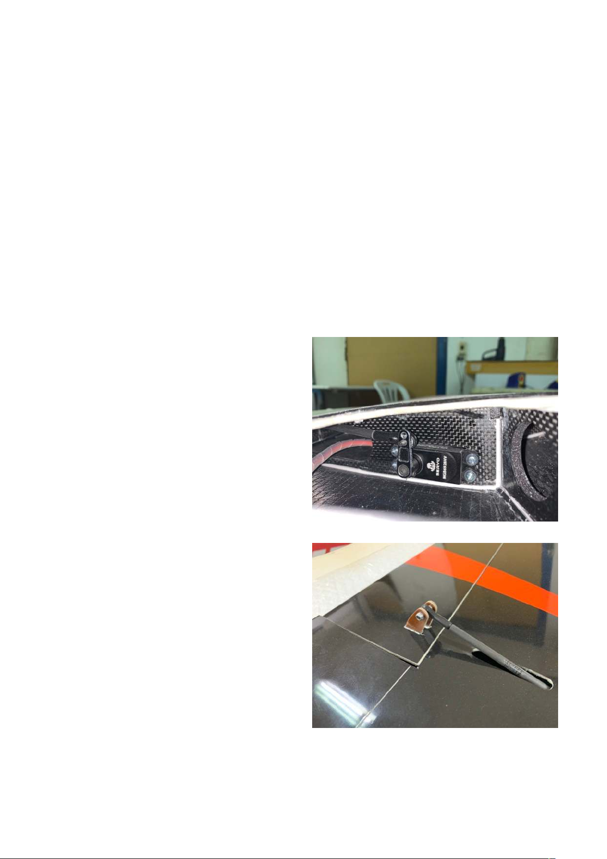
Aileron Servos: Use a short 1” / 25 mm metal servo arm. The servo arm remains inside the wing,
the linkage protrudes the bottom wing skin behind the servo and connects to the aileron control
horn in an angle. Find the linkage hardware and assemble the linkage with the M3 all thread and a
black M3 ball link at the aileron side. Depending on the type of Servo arm you use, you can opt
for an M3 ball link or a 3mm aluminum clevis,
both are included in the hardware bag. !
Note: When using the clevis, use a drop of oil on
the aluminum pin. !
Trial fit the aileron servo into the servo frame.
Feed the servo cable through first and get it
back through one of the holes in the servo rib.
Stick the special hex socket self tapping screws
through the rubber grommets before you insert
the servo finally, this will make it easier to
tighten these screws. Use a 2.5mm allen key
(we include a long one in the kit) and tighten the
servo screws well. The outer gear mount rib has
holes in strategic places to feed a long allen key
through - alternatively you can use a short allen
key though the actual hand hole between gear
and servo.!
Once the servo is installed, adjust the length of
the linkage and install the linkage. Please slide a
piece of the included 5x1 mm carbon tube over
the all thread, finalize its length and then finish
the setting of the linkage. On the aileron control
horn use an M3x16 mm bolt and a stop nut
across the two horns. If the screws is a little
short and doesn’t grab the plastic ring in the
stop nut fully, you can use a little bit blue of
Loctite. Your aileron deflection, measured at the
root, should be 35 mm (1 1/2”) up/down at 45
degree servo travel.!
Proceed with the other wing the same way. !
Page 4
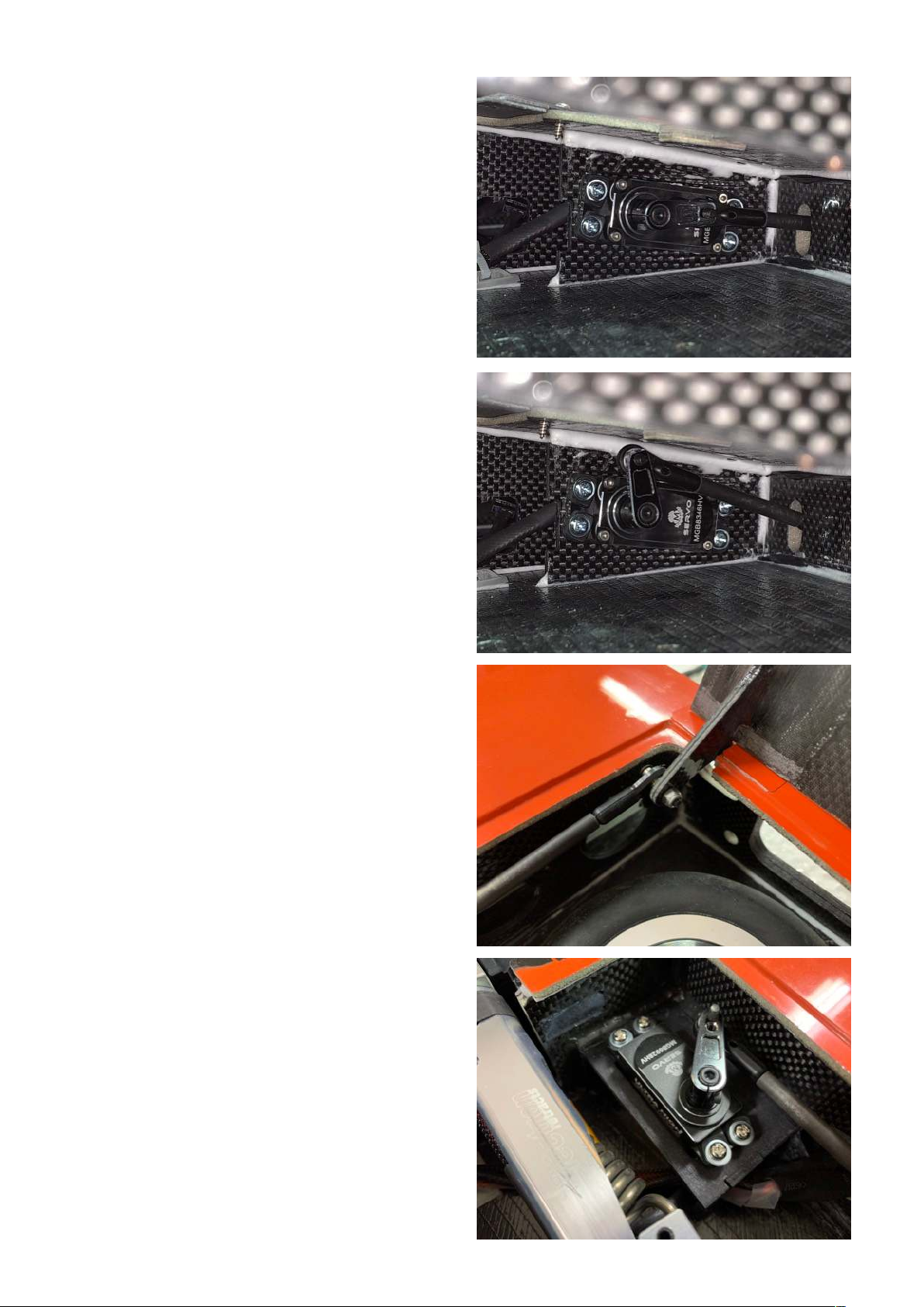
Flap Servos: Following the aileron
servo%procedure, prepare the flap linkages the
same way and also install the servos using the
supplied hex cap self tapping screws. You
should%use a short metal servo arm with 1” /
25mm. Use the strongest servo you can get, we
recommend 35-40 kg torque. It is important to
understand that the servo is to be load free
when the flap is fully deflected. That means, you
set the flap angle when fully deflected%by
adjusting the length of the linkage only, because
your servo arm will be exactly in-line with the
linkage. You will not be able to adjust this
deflection angle later with your transmitter. Set
your full flap extension angle to 50-60 degrees,
check the exact travel deflection at the aileron
root, where you can measure properly-this
should be 11 cm (4 1/2”) Ensure both wings
match.!
Once set, slide a piece of the included 5x1 mm
carbon tube over the all-thread, finalize its
length and then finish installing the linkage. Do
the same for both wings.%!
You can prepare for servo lead extensions now
or later.!
!
Gear Door Servos: Here, too, the (metal) servo
arm should be 1” / 25 mm. Follow the same
principle as on the flap servo. When the gear
door is closed, the servo arm should be exactly
in line with the linkage. !
The gear door is already factory-installed in the
wing. Since the gear door servo is set up to be
load free when the gear door is closed, allow
some tension on the linkage, some pressure on
the gear door, to hold it closed. Install the 25 kg
torque gear door servo with the linkage, which
also does need the carbon tube over the all
thread. Don’t omit it, or the linkage will bend.
The servo horn should turn towards the wing
tube when moving, to give enough clearance to
the wheel and strut at all times. Use M3 ball
links at both ends of the linkage. !
When the servos are set up correctly and the
radio is switched off, the doors are mechanically
locked and cannot be opened, unless you push
the linkage with one finger towards the wing
tube. When the gear is down, you can grab
through the slot of the open strut door, or when
the wing is off the fuselage, the gear is retracted
and all doors are closed, you can grab through
the hole in the root rib. In both cases it is easy to
unlock the gear door by pushing the linkage
towards the wing tube (forward), which unlocks
the door and then allows to fully open it by
Page 5
hand. This trick is necessary when you
assemble or disassemble the plane on a stand.!
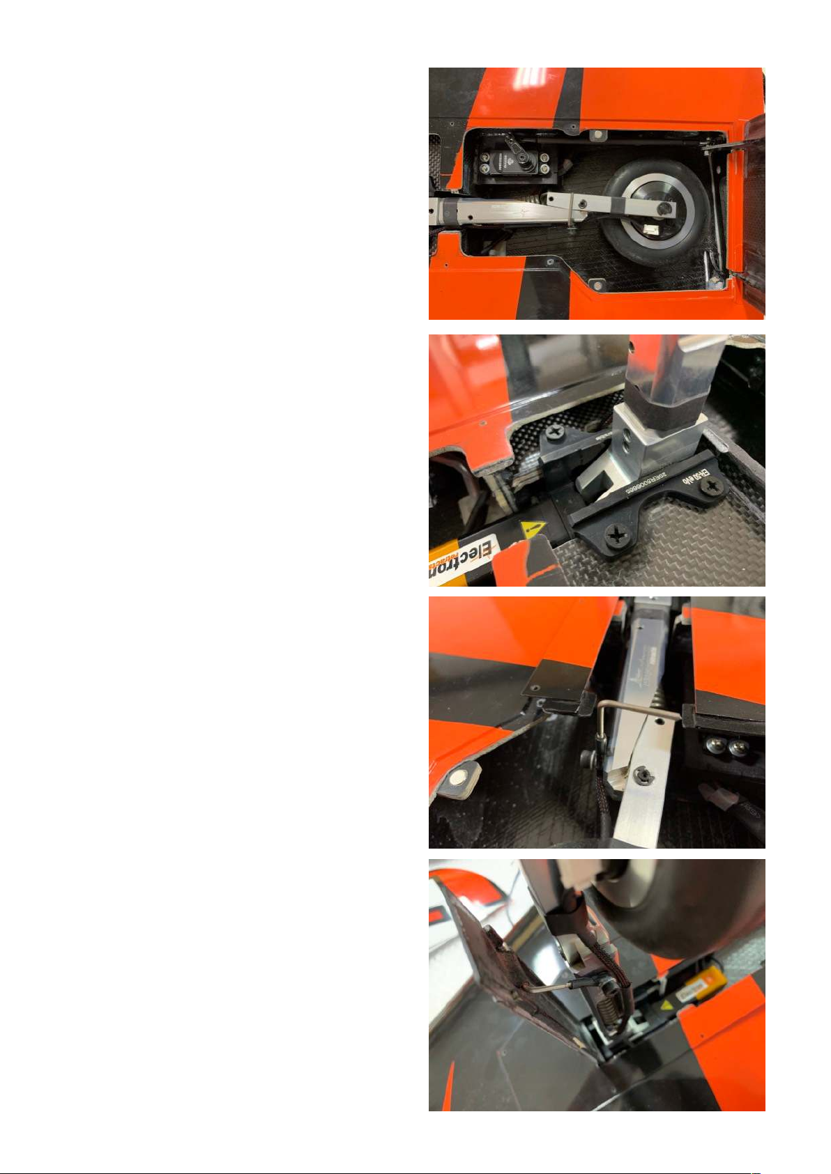
Main Gear Installation: The Electron BOLT!
gear set has been developed by Electron to fit
the CARF-Models BOLT! perfectly. Assemble
the gear, strut, wheel and brake following the
Electron manual. !
The mains will drop in and can be mounted with
the 4 self tapping screws immediately. They
need to be moved as close to the outer rib as
possible. Drill four 3mm holes in the heavily
carbon reinforced gear plate and tighten the
screws. !
Test run the gear very carefully with a small
battery pack while not letting the motor reach
the end positions mechanically. Blocking the
motors will burn them. They should only be fully
cycled when operated with the GS-200
controller. Nevertheless you will need to cycle
the gear in and out when installing and adjusting
the small strut door, so PLEASE be very careful
not to run the gear against the solid end points. !
Trial fit the gear cover with the attached small
strut door into the wing’s recess (just tape it in
place for now), while the gear is retracted. It is
important that the small strut door is being held
down by the main gear door, that’s why at the
lower end of the gear door needs to be glued a
small tab. If this tab isn’t installed this small strut
door might come off in flight. Create the small Lshaped linkage with the M2 ball link, glue a
piece of 3mm tube to the strut door and attach
the linkage to the strut. To find the right point is
a little try and error. Use very little amount of CA
glue to tack the tube to the strut door. Cycle the
gear in and out carefully, until the right position
is found. Then make a fillet with Hysol and let it
set. While doing that testing with the rest of the
gear cover taped in place, it is now time to drill
holes and fix the gear cover permanently with
the included 2.2mm self tapping screws. !
Make a final function test, making sure that the
main gear door holds down the lower end of the
strut door safely, when the gear is retracted. !
You will note that the following has been already
finished on your BOLT! in the factory. Still we
explain the procedure to make sure you
understand perfectly in case you have a repair in
this area at one point in time…!
(Once all this is done and working, trial fit the
small magnets into the small tabs of the wing
skin (drill a hole so that they fit tightly). It is
Page 6
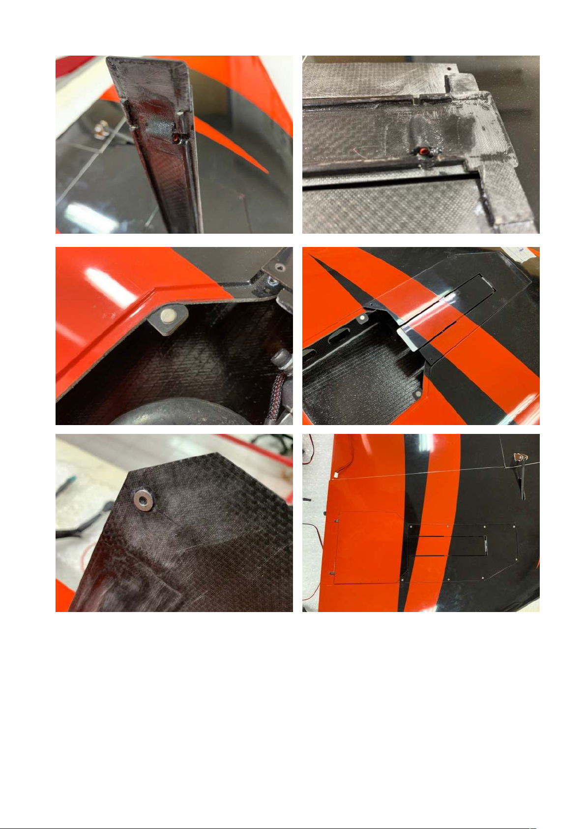
important that the washers touch the magnets in the correct flat angle, otherwise the magnetic
force will not be fully utilized. The correct procedure is to glue the washers at the exactly right
position to the door first, then click the magnets on to the washers, close the gear doors and so
sink the magnets into the recesses/holes prepared for them and glue them with Hysol in place.
Make sure no Hysol contacts the washers on the doors. That way you make sure that the contact
between magnet and washer is perfect. Once the glue has set, open the gear door and fill and reglue where needed, both the washers and the magnets to hold them in place safely. You will love
that clicking sound when the gear doors safely lock in place….)!
Now repeat the gear installation on the opposite wing, and that should complete all work on the
wing except routing all wires and placing the connectors, which can be done when all the other
parts are finished, too.!
Page 7
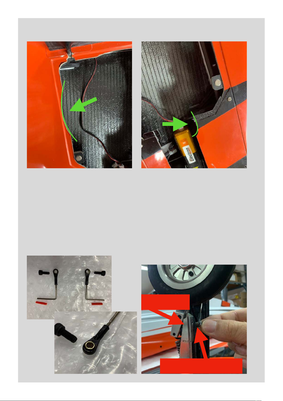
Main Gear Update!
After extensive test flights and successive move of the CG further back we have found that the
BOLT! gets pretty light on the nose gear. In order to get a little more load on the nose gear, it is
recommended to have the trialing link struts “trail” a little more than originally intended. The great
feature of the ELECTRON gear is that the trailing of the strut can be set with a set screws in the
upper strut part. Use a 2mm allen key and turn the grab screw, which is already inside the
threaded hole in the upper strut, so that the wheel moves backwards as much as possible to still
fit in the wheel well when retracted. Therefore you will need to grind a small edge of the cover as
shown on the photo, and if you want to go as much as possible, can also grind away a little of the
recess under the gear door seat. !
We have decided to pre-manufacture the small strut door holder. The M4 bolt needs to be glued
with Loctite into the same threaded hole the grab screw is underneath, once all is moving
smoothly.&
Grab Screw
Strut Holder Screw
Page 8
Stab:
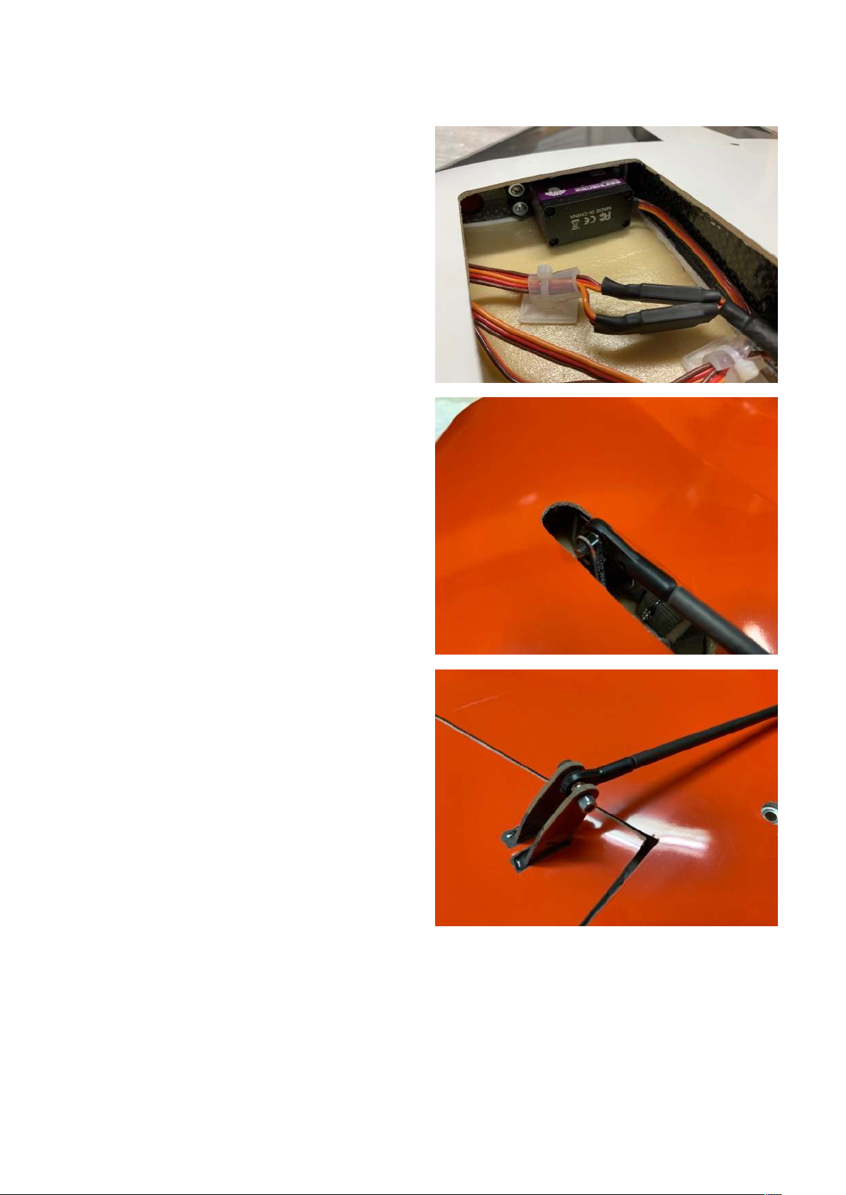
Elevator Servos: In the BOLT! stab there is no
servo hatch either. The servos are screwed into
the servo ribs in reversed direction. That means,
the servo screws are inserted into the rubber
grommets from the bottom side and the servo
gets screwed in place reversed. Before you do
that, you need to install the metal servo arm (as
short as possible, 1” / 25mm is OK but actually
still too long, 20 mm would be best. However, it
is hard to find that short aluminum servo arms,
so it is to be considered to drill a threaded hole
closer to the center of the servo. Anyway, the
servo arms protrude the bottom skin of the
stab. We only have cut a narrow slot, depending
on your servo and servo arm, you have to widen
and adjust that slot for free movement. !
Then install the servo with the hex socket cap
self tapping screws, using a ball end allen key.
Install and adjust the linkage like you did on the
ailerons, stiffen it by using a short piece of the
5x1 mm carbon tube. !
Proceed at the opposite side the same way. !
As a helpful hint: Use a servo tester and set the
servo arms to exactly vertical at 1500 ms signal,
so you can make sure that you don’t have to
use too much centering input on your
transmitter or even remove the servo to change
the arm on the spline - as this could be a quite
annoying undertaking. As a limitation you won’t
need more than 30 mm (1 1/4”) down elevator
and 35 mm (1 1/2”) up elevator deflection at
root, so ideally that should be your +/- 45
degree on the servo arm.!
Actually, on the stab that’s all what’s needed to
be done. You can try to fit it to the fuselage and
define the position for the servo connections,
which could be right and left outside and above
of the front dowels. Locate a spot where you
know you get to with your hand and decide how
long the servo leads need to be. As long as
necessary, as short as possible! !
Fin
Rudder Servo: It should be a really strong one, we recommend 35-40 kg torque. Install a 25 mm
metal servo arm, decide for the linkage you want to use and test fit the servo in the cutout. !
Align the linkage from the servo arm to the rudder control horn and adjust the size of the slot in
the fin skin. You will have to widen this slot considerably, because the hinge axis is in an angle
and the linkage will move up and down quite a bit. You will also have to grind away some of the
support spar along the tube sleeve. This is no problem because it is below the support rib and the
whole design is extremely overbuilt. Make sure, when the linkage is finalized, that you get a max
Page 9
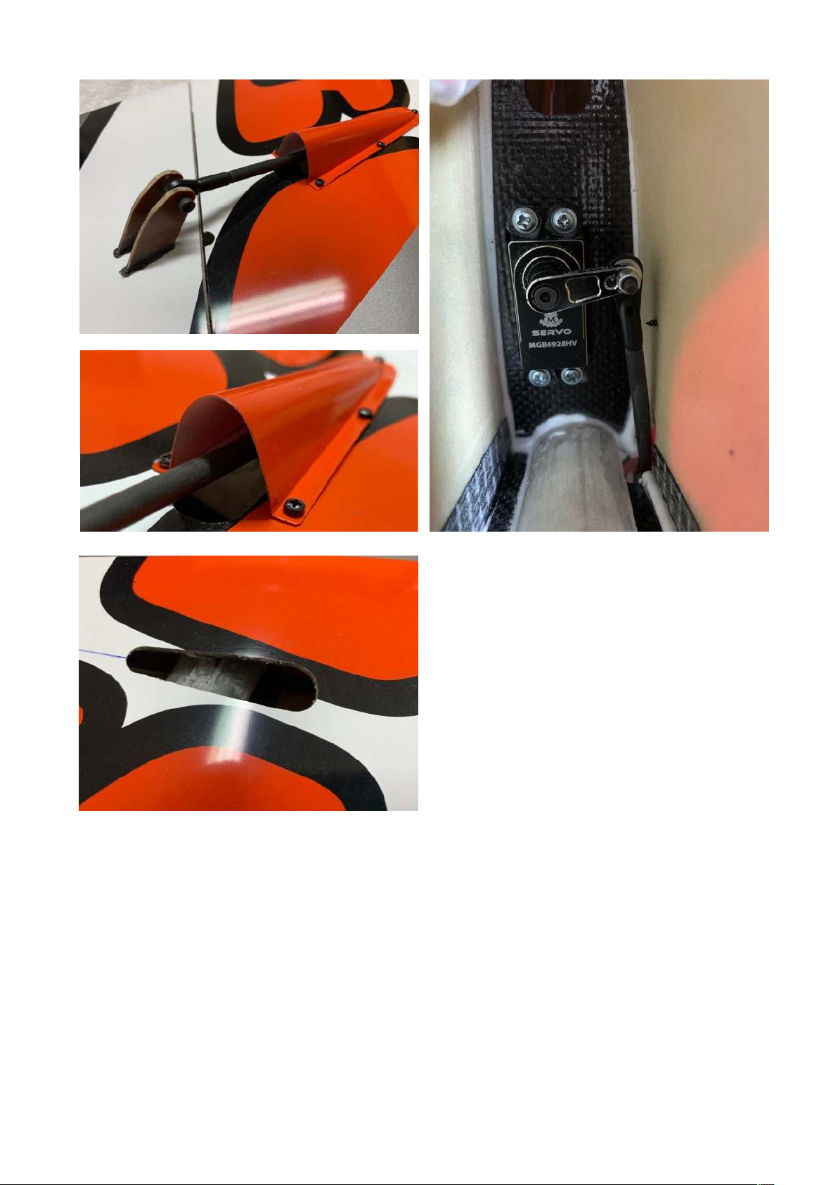
deflection of approx. 50 mm (2”) right and left,
measured at the root. The linkage should not
hit or bind with the fin tube. You should set the
neutral position of the servo arm not 90 deg to
the servo, but 90 degree to the linkage, which
is in an angle. That means, the servo arm is
pointing slightly forward when the rudder is
neutral. !
Finally screw the servo permanently in,
reinforce the linkage with a piece of 5x1 mm
carbon tube and mount it just like you’ve done
at the other control surfaces.!
Locate the position in the root rib area where
to install the socket for the servo lead and
route the servo wire accordingly.!
Front End:
Nose gear door servo: The position of the nose gear door servo is very critical, because there is
not much room where it’s installed. The linkage has to stay out of the way for the strut wheel, and
the servo body must not contact the carbon tube construction to hold nose gear and batteries.
Also the linkage must be very short, so a certain precision and care needs to be applied. !
The servo arm should be 20-25mm (3/4” - 1”). The door is already hinged and the control horn is
integrated in the front hinge. To do this job well, you will need a servo tester, in order to operate
the servo, look at the geometry and the movement and make sure that nothing is binding. !
When the door is closed, the servo arm should be as much as possible in line with the linkage. It
will not be 100% possible due to geometrical constraints, but as much as possible is desired. !
Page 10
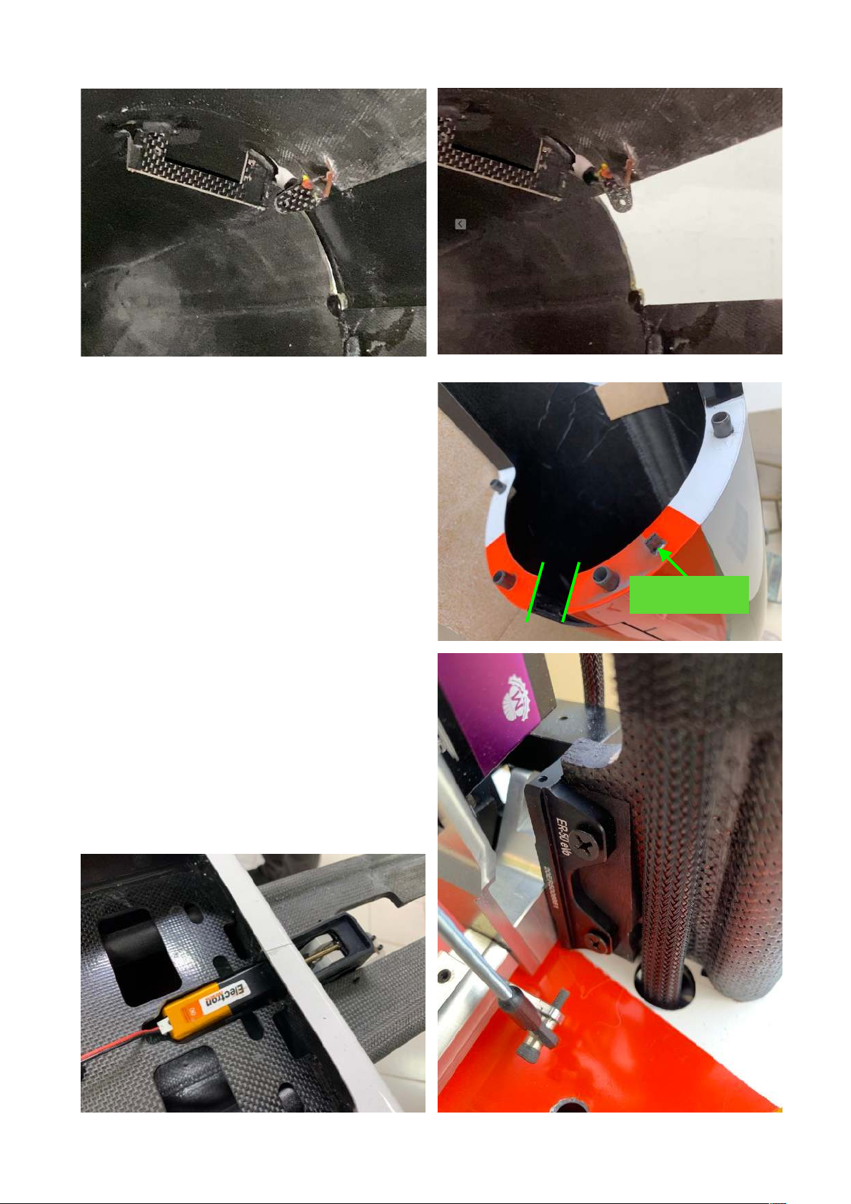
!
That keeps the load on the servo to a minimum
and applies the highest holding power to the
gear door. Because of the over-kneeing of the
servo arm and linkage a single sided ball link
must be used on the servo arm, so even here a
metal arm is a must. !
Additionally, a magnet at the front and rear end
of the nose gear door needs to be installed,
exactly as done on the main gear doors. You’ll
note that this, too, has been done in the factory
for you.!
Note: The bridge behind the nose gear door has
not been cut through before we packed and
shipped your BOLT! to have additional strength
remaining in the nose and canopy hatch. Once
you get ready to install the nose gear, you will
need to cut and remove this bridge to allow the
nose strut to pass through.!
Nose Gear: Assemble the nose gear unit, strut
and wheel according to the Electron instruction
manual. Also install the steering servo. Make
sure that the servo is oriented with the wire exit
Connector
Page 11
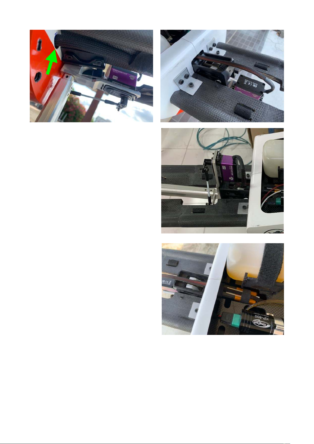
forward, away from the gear unit, otherwise it
will rub or squash the wire when retracting.
Also we strongly recommend to grind a flat spot
in the gear pin, where the control arm is
clamped. This arm has only ONE grab screw
and this should have a flat spot. All other grab
screws will not mandatorily need a flat spot
because there are multiple ones applying a lot
of force, creating sufficient friction. !
Once the gear unit is complete, it needs to be
attached to the removable gear mount.
Therefore slide the gear mount into the sleeves
of the main fuselage and check the fit. It needs
to be secured with the 2 aluminum brackets,
each with three M4 bolts. You will now see that
the gear unit is a 100 degree unit. Since it is
difficult for Electron to make this specific gear
unit (with the nose gear servo mount) retracting
100 degree, there is the only way to have it
EXTENDING to 100 degree instead. That means,
the gear unit must be angled 10 degree
upwards, resulting in a fully vertical strut when
the nose gear is down. Then the strut positions
itself in a 10 degree upward angle when
retracted, so that the nose wheel clears the gear
door. !
We include two 10 degree hard wood wedges in
the hardware bag, these get glued to the gear
plate at the correct position. Then the 4
mounting holes should be drilled with 3mm dia
and the gear unit mounted with the self tapping
screws. !
Make sure that the motor of the gear unit fits through the front face of the main fuselage and
clears the RC equipment board inside. There should be a few mm clearance around the motor,
that under no circumstances this motor could be hit or bent. As you see, you can slide the nose
dual carbon tube unit in and out easily and just secure it with two M4 bolts through the aluminum
angle brackets.!
The green arrow above shows the pass through hole for battery wires, another one is located on
the opposite side. !
Page 12
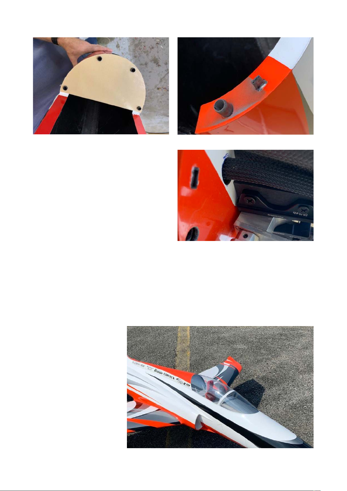
Nose Hatch Fixture: The very special design of
the CARF-Models BOLT! is that completely
removable nose section. It’s a nice feature, but
requires the installation of one servo connection
into that joint. Even though it is possible to
make it with a regular servo connector, it would
be much more rigid to use some stronger 3-pin
connector. Both connectors should be fixed in
the butting surfaces. The plastic cases should
be slightly sanded so that there is almost no
friction in the connector itself, it should slide in
and out with almost no force. Start with gluing
in the male part (which is actually the female
when referring to the crimped pins/sockets),
sticking out of the front surface of the main
fuselage approx. 8 mm. Glue that connector
solid with 5 min epoxy. !
Now grind an opening in the vertical surface of the removable nose part exactly where the
connector is to be placed. Then slide the female part on the connector in the fuselage, apply a
little 5 min epoxy on it and slide the nose hatch over it. Wait 10 min until the 5 min Epoxy has set
and then pull the nose off. Now you can crate a nice fillet around the connector in order to have a
very safe connection for the nose gear servo. !
Note: The included milled foam former will help you to stiffen the nose during transport only!!
Clear Canopy and Cockpit:
Cut the clear canopy roughly,
put i over the canopy area
from the outside and mark the
cutting line precisely with a
Sharpie. Leave approx. 6mm
(1/4”) as glue flange. Clean
away any resin build up where
the glass will seat using a
Dremel drum sander,
especially where the seam
joint tape inside is placed.
You should then use a set of
small magnets to glue the
clear canopy in place from
inside. Be careful that you do
not twist the canopy frame
while gluing. !
Page 13
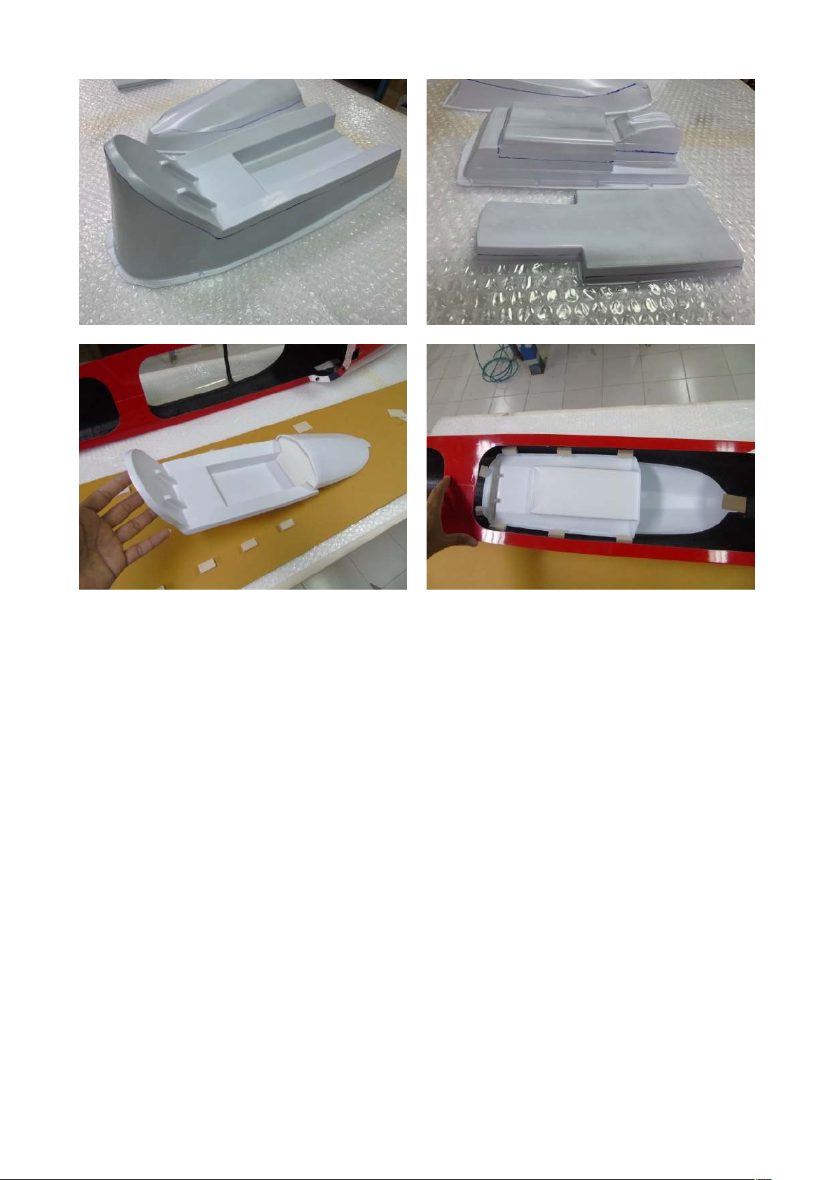
Then, when the glue has set, install the vacuum formed cockpit from inside, of course after you
painted it to your liking. If you have a few instruments or side panels lying around, they would for
sure enhance the looks of the cockpit. We have decided that the CARF-Models BOLT! looks too
good to not boast a clear canopy and a cockpit, so that little extra work is well invested and you
will love the result. use 6-8 scrap balsa blocks and a thin plywood in the front to secure it
removable.!
!
Finally, slide the nose hatch on and make sure it slides all the way to the end. You might have to
sand a little more chamfer to the pins/carbon tubes to catch the holes easier. Make sure that the
single bolt behind the canopy can be inserted and tightened easily. That will finish the plane to the
point that it can be assembled and stand on its wheels. !
First assembly:
Put the fuselage on a stand. Slide the wing and stab tube in, make sure that they are not too lose
and not too tight. If they are tight, you can sand the sleeves slightly, if they are a little lose, it’s not
a problem as long as they do not really show significant movement. If that is the case, (and it
should not) a simple remedy could be to paint the loose sleeve with thin resin from inside, using a
long brush. Once that resin has cured completely, you might have to sand the inside smooth in
order to get the desired fit of the carbon tube. Unfortunately sometimes it is hard to control the
tolerances of the carbon tube suppliers and even though we try our best, sometimes such a
tolerance problem can occur. !
Tighten wings, fin and stab with its bolts and make sure everything fits nicely, nothing binds or
locks up. Now take the time to locate where you want to install your connectors between the
parts, mark the positions, remove wings, stab and fin again and prepare for installation of these
Page 14
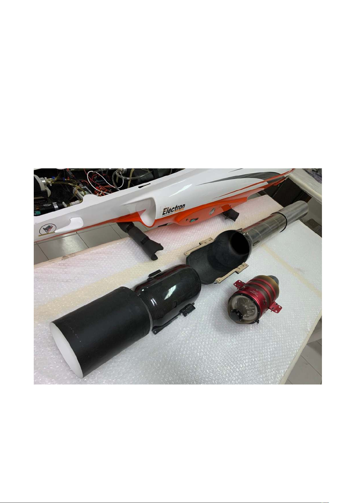
connectors. You can finish the routing of the wires in wing, stab and fin now. You should not wait
with the final installation of the connectors in the fuselage because the more equipment is
installed, such as engine and fuel tanks, the harder it will get to access the areas where to route
wires and permanently install the connectors. Do this now and just route the loose ends of the
wires to the front, below the equipment board, mark them to identify them later, leave them long
enough and shorten as needed before crimping the connectors to the other ends. The rest of the
work will now be inside and around the main fuselage, so you can put all other parts aside for
now.!
Engine, bypass, thrust tube and fuel tanks:
General: Now comes the next specialty of the CARF-Models BOLT: The installation of the engine.
It’s a fact that you won’t find an aerodynamically cleaner engine installation in any large sport jet
on the market, no matter where you look. Such a clean and slick engine installation comes,
however, with some added need of precision and care, and eventually with some special
procedures. That’s no different with the CARF-Models BOLT! !
Basically the engine is bolted into the carbon bypass and creates one integrated unit. That unit is
then bolted in place in the fuselage on longitudinal rails. To get it there, it gets inserted from the
rear of the fuselage, passes through the ring former holding the fin tube, and though the rear main
former of the engine mount. Even the thrust tube is attached to the integrated bypass before it is
moved to its mounting place. Alignment of the thrust tube is a no-brainer because it is installed
with 3 steel springs being flexible, adjustable and totally safe. And it can be removed and reattached in no time, if needed. !
Page 15
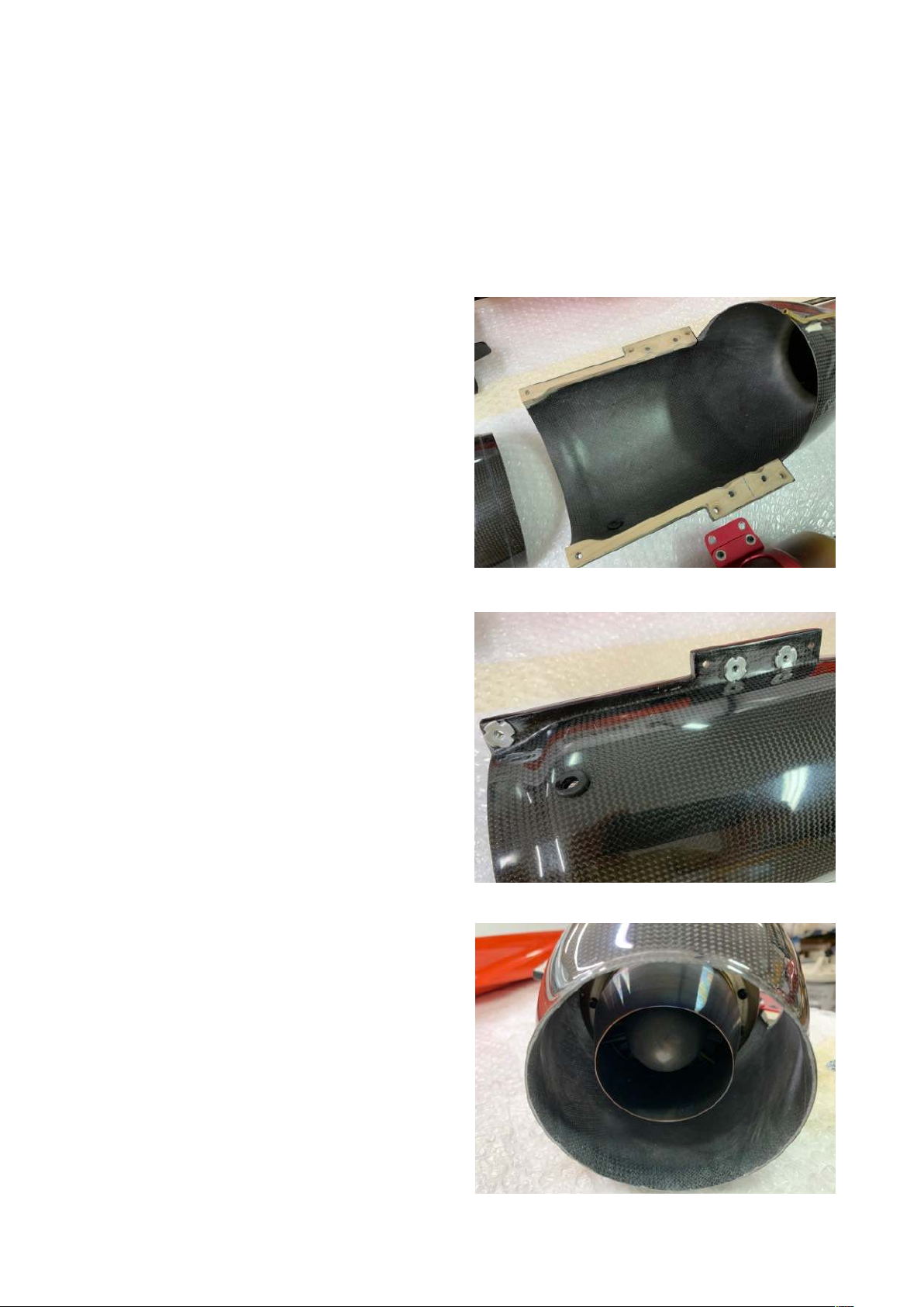
Once this engine unit is pushed inside the fuselage and rests at its final location, it is bolted to the
rails with four M4 bolts. The engine itself, however, can then be accessed and even removed and
re-installed by just removing the bypass cover, through the top opening of the fuselage in
minutes. It also can be removed as a fully integrated unit through the rear of the fuselage. !
A fully ducted engine installation, together with a sleek fuselage, poses also a great challenge for
placing the fuel. The CARF-Models BOLT! has 2 saddle tanks with 5.6 Liter volume installed
which, due to the geometry of the factory installed intake ducts, are placed exactly in the CG.
They can be removed quickly when the intake liner is removed and the integrated engine unit is
slid back 25 cm (10”).!
Integrated Engine Unit: Put the bypass cover
on the empty bypass, bolt it down at the front
edges with two M4x10 allen bolts and trial fit
this empty shell to its mounting rails in the
fuselage. Insert from the rear of the fuselage.
Both the duct and the rails have its mounting
holes drilled. Make sure the four M4 mounting
bolts can be inserted and tightened without
binding. If necessary, rework the holes and the
rails slightly to fit. Access is no problem with a
good quality ball driver.!
After removing the empty bypass shell and
taking off the cover, drill the holes for the turbine
specific engine mount into the carbon bypass.
Position should be centered around the
embossed area in the cover. In case your engine
mount is much wider or longer than the
KingTech mount (which we used for the
prototype) you can alter and cut the cover in
this area. It is not necessary to keep this area all
perfectly closed and sealed.. You can cut off
material from the cover as needed, as long as it
can be fixed as designed (lip in rear and 2 bolts
in front). Install M4 T-Nuts from the bottom of
the bypass. Since the engine rails are designed
to clear these T-Nuts, you could glue them
reversed with Hysol against the carbon surface.
In case your mourning bolt pattern is wider, you
might have to rework the recess area in the
engine mounting rails inside the fuselage. !
Make sure that the bypass doesn’t get deformed
when bolting the engine in place. Also make
sure that the engine’s exhaust cone is centered
in the outlet cone of the bypass. Some engines,
e.g. JetCat, require 5-6 mm packing under the
engine mount to center the engine. That will
have to be adjusted individually. The rear edge
of the engine’s exhaust cone should be 20-30
mm forward of the rear edge of the carbon
cone. That’s why it is so great to be able to
install the engine into the bypass outside of the
airplane, where everything is perfectly
accessible. !
Once the engine is perfectly placed and
centered and the bypass cover can be easily
mounted, grind one or two notches in the front
Page 16
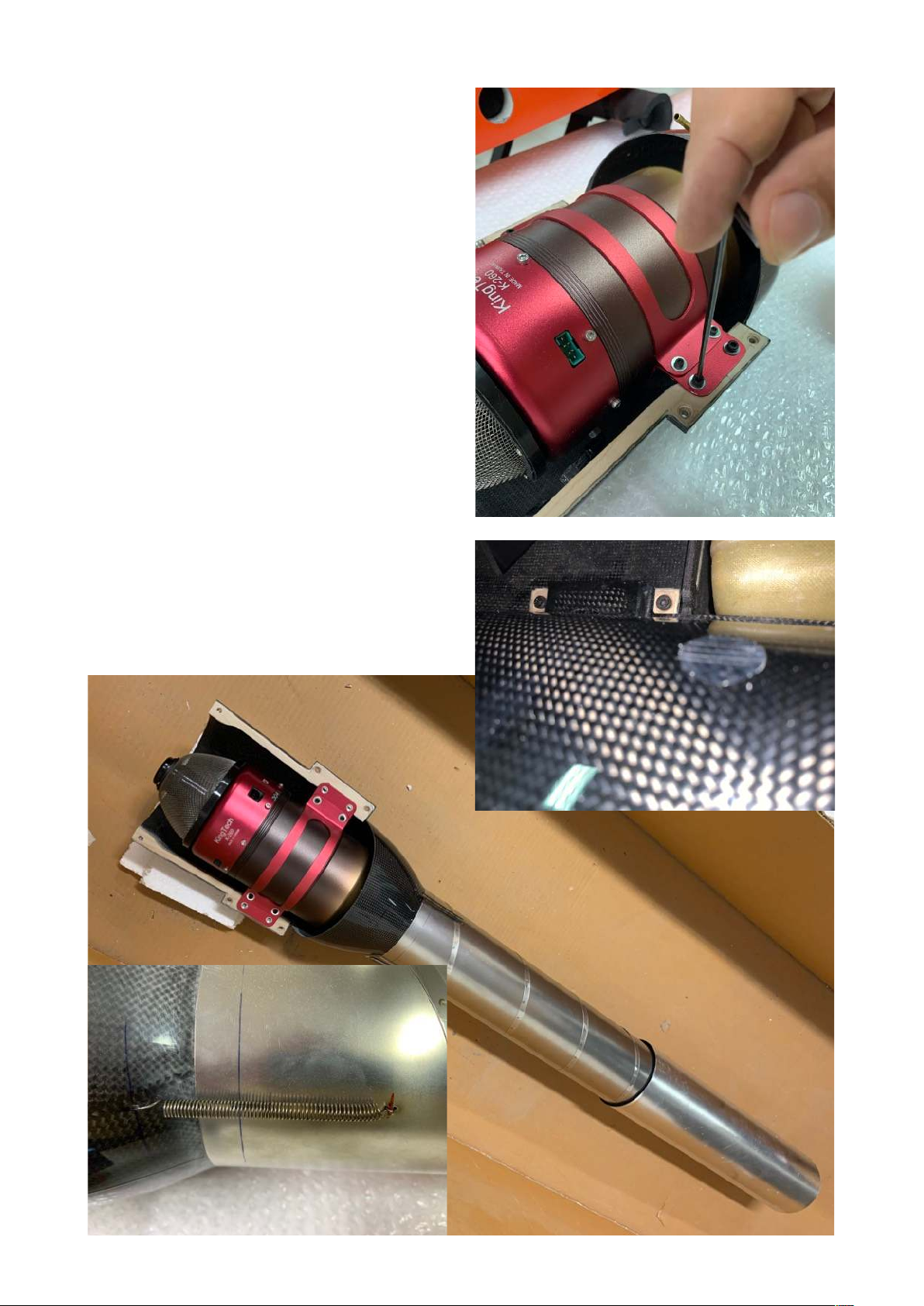
edge of the bypass cover to allow the wires to
go through. We recommend to only notch the
front edge of the cover, instead of drilling holes
and feeding the wires through these holes to
plug them into the engine, simply because in
the tight space it is easier to put the bypass
cover on AFTER the connectors are plugged in
to the engine. !
Locate the best position and then drill a hole for
the fuel line into the bypass and install a half
meter long piece of fuel line in the engine. Plug
this fuel line at the loose end so that no dirt can
get in. !
Then trial fit the thrust tube. It must slide over
the rear cone by 10-15 mm. Drill the stainless
tube and the rear cone of the bypass with each
3x 1.5mm holes, at 120 degrees around the
perimeter, 40 mm from the edges. Then hook
the included thrust tube springs up and make
sure the thrust tube is pulled with authority
towards the cone, still allowing angular
corrections easily. !
What you have in hand now we call the
integrated engine unit, which looks a little like
a huge pulse jet engine… Put this assembly
aside for now and plumb and install the fuel
saddle tanks.!
3 springs 120 deg around
Page 17
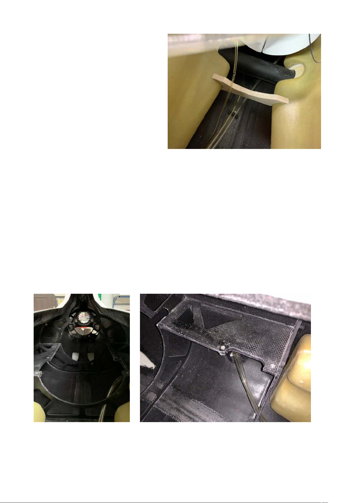
Fuel tanks: Plumb the saddle tanks now.
We only use 2 lines (one in, one out). The
out line is the clunk line. Put a brass tube
in the baffle area so that the baffle cannot
damage the fuel line. The in-line will be
bent so that the tube reaches the top
corner of the fuel tank. !
We plumb these saddle tanks parallel. That
means, the fuel lines and vent lines of both
tanks get connected at exactly the same
length, and one single line goes to the
header tank and the bent position at the
bottom of the fuselage. We use felt clunks
in these saddle tanks since only 50% of
the total fuel flow is pulled through each
felt clunk. You will see that with that setup
you won’t get ANY air in your header tank at all. All equipment needed for the plumbing of the
saddle tanks is included in the kit. It is advisable that you take a little time and make a leak and
function test while still outside of the fuselage, so that you can permanently install them in the
fuselage with peace of mind. !
It makes sense to use the included “push in fittings”, simply because you can remove the fuel
lines easily and thus remove the tanks for maintenance quickly without having to cut fuel lines.!
We do not supply a UAT because on these high end jets it has become normal that everyone has
it’s preferred UAT and uses whatever he thinks is best. Please follow the UAT manufacturer’s
instructions when plumbing and installing. UAT and fuel pump should be installed on the most
forward fixed part of the equipment board. It will help to keep the CG at the right spot. !
Slide the saddle tanks from the rear into their space in the fuselage and hook them over the wing
tube. We use one or two (veeeery small) dots of PU foam to hold them in place - BUT only after all
wring has been installed. IF you have not pulled and fixed the wires for the elevator, rudder and
wing servos yet, you should do that right now, otherwise you will have to remove that integrated
engine unit one more time when the final wiring is being installed. !
Installing the integrated engine unit in the fuselage:
Remove the thrust tube from the carbon bypass. Then insert the carbon bypass through the stab
saddle and push it backwards through the circular hole in the rear. Hook up the thrust tube with
the 3 springs and then push the completed integrated unit forward. It could be helpful to have a
Page 18
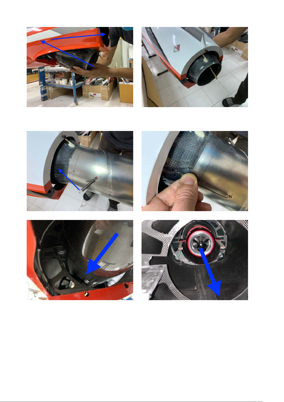
second pair of hands available, to channel the unit through the openings in the formers and then
place it on the mounting rails. !
Once you are confident that you do not need to access the area inside the fuselage behind the
engine formers anymore, bolt the integrated engine unit tight. Attach the rear fuselage cone to
hold the thrust tube in center. !
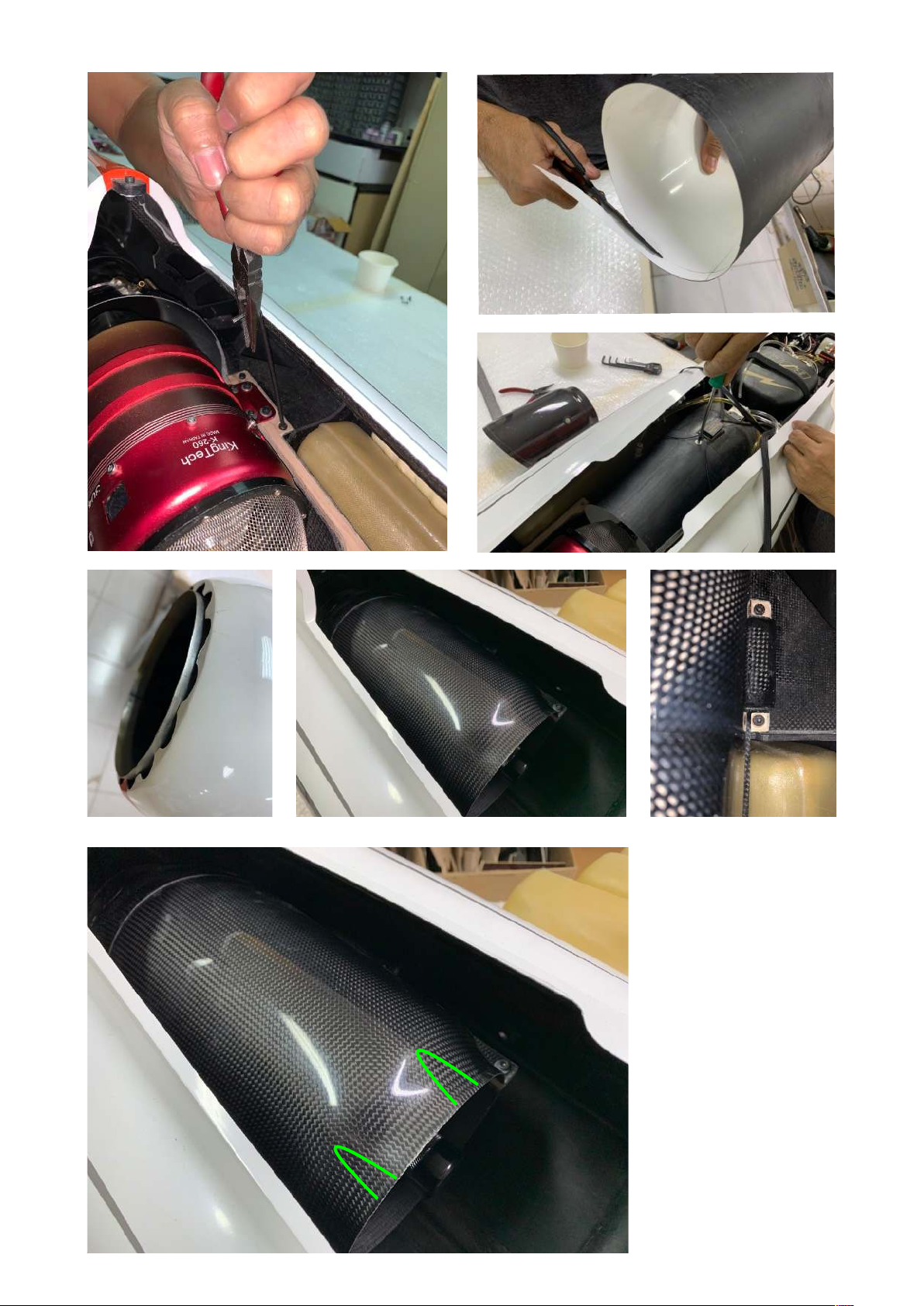
Now you will see that once you remove the bypass cover (only loosen two bolts in the front
corners) you can access the engine freely, you can even remove that engine from the bypass and
take it out within a few minutes through the fuselage opening above. Then install the intake liner,
you can adjust its length with scissors easily. It should not be too long, so that the airflow will be
as smoothly as possible around the engine. Overlap into the carbon duct should be 10 mm max.
The intake liner is fixed with one self tapping screw into the fixed intake duct.!
123
4
Page 19
Congratulations: !
You now completed the
most complex part of
your BOLT! build: The
installation of the
propulsion system. !
min 5 mm
max 10 mm
cut out for cable
Page 20
Smoke System
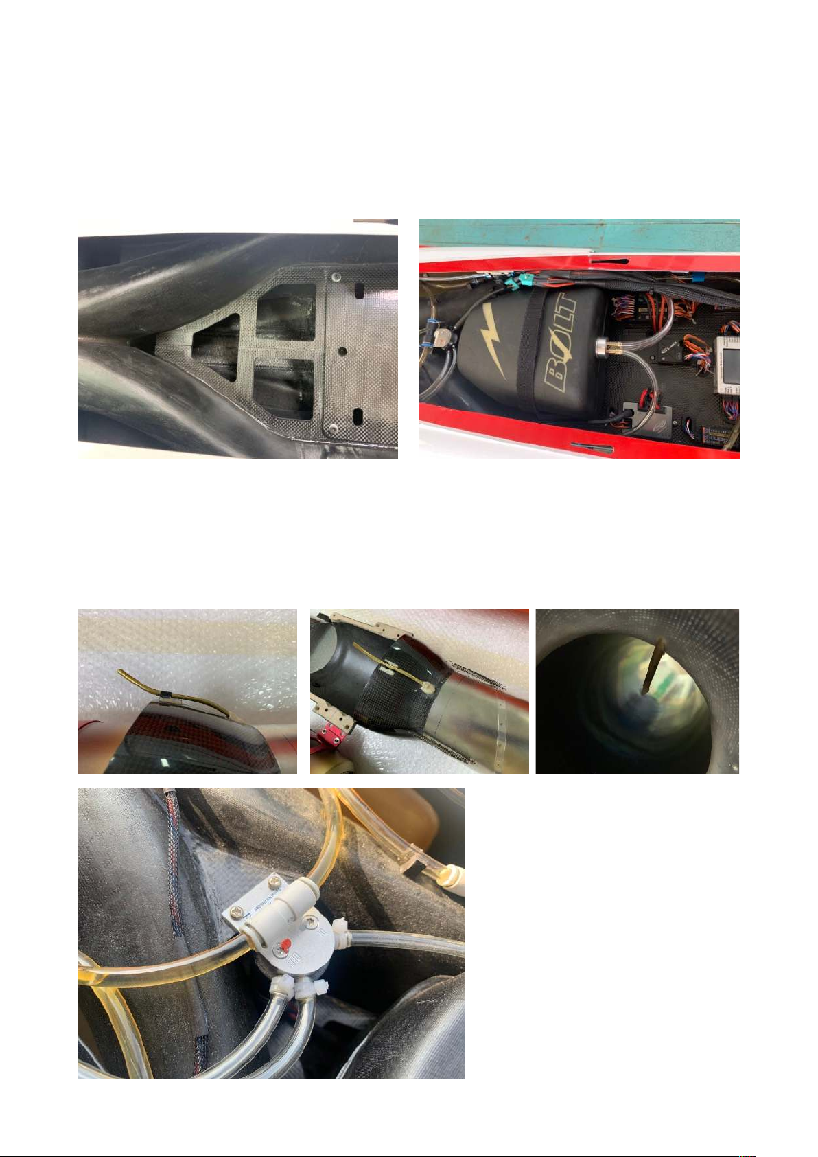
Plumb the smoke tank the same way you were plumbing the fuel saddle tanks. Fix the smoke
tank with a strap of double sided velcro in the V of the intake ducts on top of the equipment
board. We are using two balsa spacers to elevate the smoke tank about 20 mm above that
equipment board, which makes it easier to access the M4 bolts and to handle the removable part
of the equipment board.!
Build one (or two, depending on the smoke pump type you use) smoke injectors. This is a very
individual task, but our recommendation is to make sure you can easily remove the injectors in
order to remove the integrated engine unit through the rear of the fuselage without a brass tube
sticking out of the system too far and getting in the way. IF you install a single smoke injector you
can install it from the top through the carbon cone, as long as it is short enough and slightly out of
center, so that it can pass the fin tube socket when sliding the duct in from the rear. You should
also take care that the smoke injector
tube clears the canopy hatch when
sliding it back into position on the
main fuselage, and that it isn’t in the
way when removing the bypass cover
to quickly access the engine. A bit
tricky, but it can be done and it is the
best way to do it.!
Finally install the Powerbox Smoke
pump into in the V of the intake ducts
as shown on the photos. Of course
other smoke pumps can be installed
as well, but the Powerbox Pump is
perfectly suited to mount in the tight
space.!
Page 21
RC-Equipment
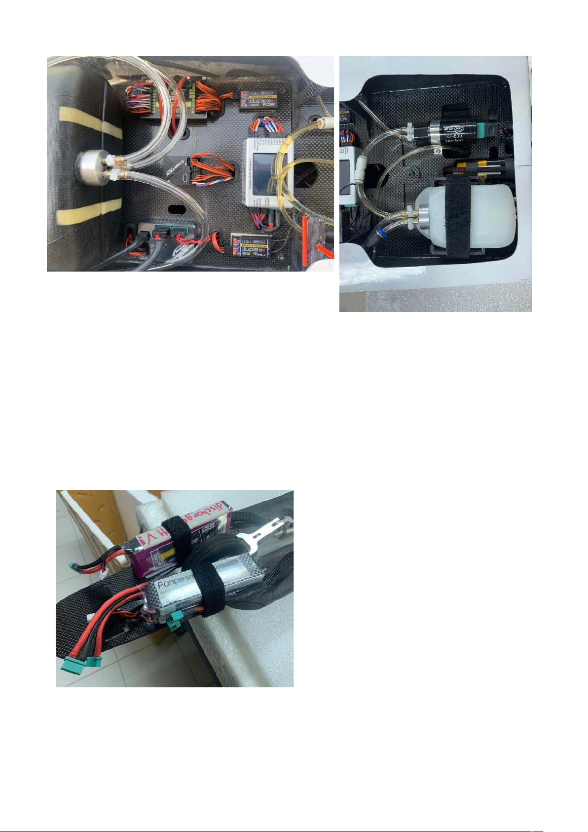
All equipment can be installed on the removable part of the equipment board. Rubber grommets
should be used to protect wires from rubbing against the carbon fibre edges. All wires can be
routed hidden below the board, creating an unbelievably clean way to install all electronic
equipment. Make sure that any gyro (Cortex Pro, iGyro or a Mercury with iGyro) get installed in the
center of the board. Engine ECU on the right, any receiver, Jeti Central Box on the left, Electron
GS-200 controller forward. Satellite receivers can be fixed on the board but antennas should be
routed away from the carbon. A good place is to mount one the intake ducts and another one, in
case you have a long patch cable availalbe, at the nose board, right in front of the nose wheel,
even forward of the batteries. The receiver and turbine batteries should be fixed with Velcro straps
along the sides of the nose wheel cutout. The battery wires should be fed through the front face of
the main fuselage below the nose gear tray
and then fixed with 1-2 small velcro loops (not
cable ties) to the board, which allows you to
quickly unhook the wires and take the nose
gear board off. Of course you have to be
careful that the nose gear cannot get tangled
in the battery wires.!
We recommend to use the Powerbox heavy
duty servo wire and create a harness by
CRIMPING and not soldering. Do NOT use
standard servo extensions as they will never
have the best suited length and quickly create
a big wiring mess. You have already decided
for the type and location of the connectors to
wings, stab and fin, so you can route these
wires and finalize the connector installation
before mounting the integrated engine unit
and the fuel tanks.!
Please note: There is a lot of carbon fiber used in this airframe.
Keep all antennas in the nose cone / canopy area for good reception!
Page 22

Final Setting
Center of Gravity: Initially we hook a wire loop around the wing fixing bolts. That position is
slightly nose heavy. To reach this point (using a KingTech 260 G2 engine, 2x 3000 mAh LiPo
receiver packs and 1x 3700 mAh 3S LiFe turbine battery) you might have to add 250-300 g of lead
in the nose. However, after a few flights, you will find that you can remove this lead progressively
to zero. !
Control Throws: When using the recommended servo arm length your control throws should be
already close. Here is a list summarizing the high rate values measured at the root, if not
mentioned otherwise:!
Aileron: 35 mm up/down!
Elevator: 35 mm up, 30 mm down!
Rudder: 50 mm right/left!
Flaps 110 - 115 mm (measured towards aileron root, set by flap linkage length at full over-kneeing
of servo arm)!
!
For low rates you can reduce all control throws by 30%, but that is very much up to your personal
preference. The take off flap position should be set to 30 mm.!
Gear Programming: For the GS-200 programming of the landing gear, you can have the gear
doors close when the gear is down, that will give you the cleanest setup. Make sure you provide
constant servo power to the gear doors and do not only refresh every 5 or 15 seconds, that
would definitely cause gear doors to depart at high speeds. !
Gyro: In case you are using a Cortex Pro Gyro, run the setup procedure with the high rates given
above and do not use any heading hold. We have put the gain value on flight modes (flight,
takeoff and landing) and have 20%, 25% and 35% in the respective flight modes. For initial setup
use 25% as a base value and then work with with an adjustment window of +/- 15% to find your
preferred settings for fast flights, take off and landing. !
We do not have any iGyro setting values available yet.!
———————————————————————————————————————————!
This manual has been created while the 1st and 2nd Prototype of BOLT! have been test flown. We
have made subsequent changes in the production line with whatever we found during the test
flights to be improved. So, the first handful of airplane might differ slightly from the details shown
in this manual, but all values given here are current and can be immediately used for any BOLT!
delivered. !
Thank you for being a loyal customer, for choosing a fine and technologically very sophisticated
aircraft over many other, maybe simpler built choices on the market. We are sure you will enjoy
every minute of building and flying your BOLT! - and taking it to its limits. !
Thank you!!
Andreas Gietz
 Loading...