

Integrated Control Solutions & Energy Savings
User manual
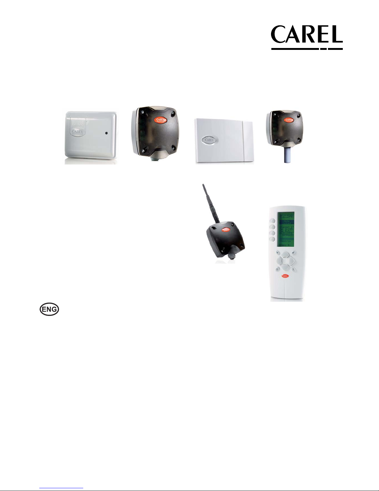
For monitoring environmental conditions
• Temperature
• Humidity
• Light
Wireless sensors


3
ENG
“Wireless probes” +0300030EN - rel. 1.0 - 16.07.2010
WARNINGS
CAREL bases the development of its products on decades of experience
in HVAC, on the continuous investments in technological innovations
to products, procedures and strict quality processes with in-circuit and
functional testing on 100% of its products, and on the most innovative
production technology available on the market. CAREL and its subsidiaries
nonetheless cannot guarantee that all the aspects of the product and the
software included with the product respond to the requirements of the nal
application, despite the product being developed according to start-of-theart techniques.
The customer (manufacturer, developer or installer of the nal equipment)
accepts all liability and risk relating to the con guration of the product in
order to reach the expected results in relation to the speci c nal installation
and/or equipment.
CAREL may, based on speci c agreements, acts as a consultant for the positive
commissioning of the nal unit/application, however in no case does it accept
liability for the correct operation of the nal equipment/system.
The CAREL product is a state-of-the-art product, whose operation is speci ed
in the technical documentation supplied with the product or can be
downloaded, even prior to purchase, from the website www.carel.com.
Each CAREL product, in relation to its advanced level of technology, requires
setup/con guration/programming/commissioning to be able to operate in
the best possible way for the speci c application. The failure to complete such
operations, which are required/indicated in the user manual, may cause the
nal product to malfunction; CAREL accepts no liability in such cases.
Only quali ed personnel may install or carry out technical service on the
product.
The customer must only use the product in the manner described in the
documentation relating to the product.
In addition to observing any further warnings described in this manual, the
following warnings must be heeded for all CAREL products:
• prevent the electronic circuits from getting wet. Rain, humidity and all
types of liquids or condensate contain corrosive minerals that may damage
the electronic circuits. In any case, the product should be used or stored
in environments that comply with the temperature and humidity limits
speci ed in the manual.
• do not install the device in particularly hot environments. Too high
temperatures may reduce the life of electronic devices, damage them and
deform or melt the plastic parts. In any case, the product should be used
or stored in environments that comply with the temperature and humidity
limits speci ed in the manual.
• do not attempt to open the device in any way other than described in the
manual.
• do not drop, hit or shake the device, as the internal circuits and mechanisms
may be irreparably damaged.
• do not use corrosive chemicals, solvents or aggressive detergents to clean
the device.
• do not use the product for applications other than those speci ed in the
technical manual.
All of the above suggestions likewise apply to the controllers, serial boards,
programming keys or any other accessory in the CAREL product portfolio.
CAREL adopts a policy of continual development. Consequently, CAREL
reserves the right to make changes and improvements to any product
described in this document without prior warning.
The technical speci cations shown in the manual may be changed without
prior warning.
The liability of CAREL in relation to its products is speci ed in the CAREL general
contract conditions, available on the website www.carel.com and/or by
speci c agreements with customers; speci cally, to the extent where allowed
by applicable legislation, in no case will CAREL, its employees or subsidiaries
be liable for any lost earnings or sales, losses of data and information, costs of
replacement goods or services, damage to things or people, downtime or any
direct, indirect, incidental, actual, punitive, exemplary, special or consequential
damage of any kind whatsoever, whether contractual, extra-contractual or
due to negligence, or any other liabilities deriving from the installation, use or
impossibility to use the product, even if CAREL or its subsidiaries are warned
of the possibility of such damage.
DISPOSAL
INFORMATION FOR USERS ON THE CORRECT
HANDLING OF WASTE ELECTRICAL AND ELEC-
TRONIC EQUIPMENT (WEEE)
In reference to European Union directive 2002/96/EC issued on 27 January
2003 and the related national legislation, please note that:
1. WEEE cannot be disposed of as municipal waste and such waste must be
collected and disposed of separately;
2. the public or private waste collection systems de ned by local legislation
must be used. In addition, the equipment can be returned to the
distributor at the end of its working life when buying new equipment;
3. the equipment may contain hazardous substances: the improper use or
incorrect disposal of such may have negative e ects on human health and
on the environment;
4. the symbol (crossed-out wheeled bin) shown on the product or on the
packaging and on the instruction sheet indicates that the equipment has
been introduced onto the market after 13 August 2005 and that it must
be disposed of separately;
5. in the event of illegal disposal of electrical and electronic waste, the
penalties are speci ed by local waste disposal legislation.
Warranty on materials: 2 years (from the date of production, excluding
consumables).
Approval: the quality and safety of CAREL S.P.A. products are guaranteed by
the ISO 9001 certi ed design and production system.
Important warning!!!
The rTM SE system devices are
incompatible with the Carel rTM system,
due to an improvement made to the
ZigBee wireless communication
protocol.

4
ENG
“Wireless probes” +0300030EN - rel. 1.0 - 16.07.2010

5
ENG
“Wireless probes” +0300030EN - rel. 1.0 - 16.07.2010
Content
1. INTRODUCTION 7
1.1 Wireless monitoring devices ........................................................................7
1.2 Codes ................................................................................................................. 8
1.3 Terminology .................................................................................................... 9
1.4 Advantages of the wireless system .............................................................9
1.5 Type of Carel wireless network (MESH) .................................................. 10
1.6 General features of the system .................................................................. 11
1.7 Using the Router ........................................................................................... 11
1.8 General notes ................................................................................................ 11
1.9 Reference standards ..................................................................................... 12
1.10 Battery life ....................................................................................................... 12
1.11 List of sensor system variables (alphabetical order) ............................. 12
2. BP SE SENSOR (BUILT-IN PROBE) 13
2.1 Functions implemented and supervisor variables available ...............13
2.2 Sensor confi guration .................................................................................... 13
2.3 Sensor activation ........................................................................................... 14
2.4 Technical specifi cations ................................................................................ 15
2.5 List of parameters and variables, BP SE Sensor ..................................... 16
2.6 Installation notes ............................................................................................17
2.7 Physical dimensions ......................................................................................17
2.8 Replacing the battery in the BP SE Sensor ...............................................17
2.9 Application examples ....................................................................................17
3. EP SE, SA, SI SENSORS AND CI PULSE COUNTER 18
3.1 Parameters and functions ........................................................................... 18
3.2 Description of the acquisition process ..................................................... 18
3.3 Device confi guration .................................................................................... 18
3.4 Binding procedure ........................................................................................ 19
3.5 Resetting the sensor (unbinding) .............................................................. 19
3.6 General warnings ......................................................................................... 19
4. EP SENSOR (EXTERNAL PROBE) 20
4.1 Functions implemented ...............................................................................20
4.2 Parameters and functions ........................................................................... 20
4.3 Technical specifi cations ................................................................................20
4.4 List of parameters and variables, EP SE Sensor .....................................21
4.5 EP SE Sensor installation notes ..................................................................22
4.6 EP SE physical dimensions .........................................................................22
4.7 EP SE electrical connections .......................................................................22
4.8 Application example .....................................................................................22
5. SA ROOM SENSOR 23
5.1 Functions implemented and supervisor variables available ...............23
5.2 Technical specifi cations ................................................................................24
5.3 List of parameters and variables, SA Sensor ........................................... 24
5.4 Sensor installation notes .............................................................................25
5.5 Physical dimensions ..................................................................................... 25
5.6 Application example .....................................................................................25
6. SI INDUSTRIAL SENSOR 26
6.1 Functions implemented and supervisor variables available ...............26
6.2 Technical specifi cations ................................................................................27
6.3 List of parameters and variables, SI Sensor ............................................ 28
6.4 SI Sensor installation notes ......................................................................... 28
6.5 Physical dimensions ..................................................................................... 29
6.6 Application example .................................................................................... 29
7. CI PULSE COUNTER 30
7.1 Functions implemented ...............................................................................30
7.2 Parameters and functions ........................................................................... 30
7.3 Technical specifi cations ................................................................................ 30
7.4 List of parameters and variables, CI Pulse Counter ..............................31
7.5 CI Pulse Counter installation notes ...........................................................32
7.6 CI Pulse Counter physical dimensions .....................................................32
7.7 CI Pulse Counter electrical connections ................................................... 32
7.8 Connection example ................................................................................... 32
8. AP ACCESS POINT 33
8.1 Main functions ...............................................................................................33
8.2 Parameters and functions ........................................................................... 33
8.3 Confi guration ................................................................................................ 33
8.4 Setting the address .......................................................................................33
8.5 Binding procedure ........................................................................................34
8.6 Resetting the device .....................................................................................34
8.7 Serial communication parameters ............................................................34
8.8 Table of LED status .......................................................................................35
8.9 Technical specifi cations ................................................................................35
8.10 List of Access Point system variables (alphabetical order) ..................36
8.11 List of parameters and variables, Access Point versione ..........................
Modbus RTU
® .....................................................................................................................................
37
8.12 Installation notes ...........................................................................................37
8.13 Electrical connections and physical dimensions ....................................38
9. RO ROUTER 39
9.1 Parameters and functions ......................................................................... 39
9.2 Binding the Router to the Access Point ....................................................39
9.3 Resetting the device .....................................................................................40
9.4 Table of LED status .......................................................................................40
10. ROUTERS WITH OTHER INTEGRATED FUNCTIONS 41
10.1 EP1 Router-Sensor ........................................................................................ 41
10.2 RB Router-Bridge........................................................................................... 41
10.3 RA Router-Actuator ....................................................................................... 42
10.4 Functions implemented ...............................................................................42
10.5 RC Router-Pulse Counter ............................................................................42
10.6 Technical specifi cations ................................................................................43
10.7 List of Router system variables (alphabetical order) .............................43
10.8 List of Router parameters .........................................................................44
10.9 List of RA Router-Actuator parameters ..................................................... 44
10.10 Installation notes ...........................................................................................44
10.11 General warnings ........................................................................................46
11. GENERAL NOTES 47
11.1 Notes for correct installation ...................................................................... 47

“Wireless probes” +0300030EN - rel. 1.0 - 16.07.2010
6
12. RTM SE HANDHELD 48
12.1 General Features ........................................................................................... 48
12.2 Operating modes ..........................................................................................48
12.3 Main menu .....................................................................................................48
12.4 Scan Energy ....................................................................................................48
12.5 Scan Networks ............................................................................................... 49
12.6 Scan Connection ........................................................................................... 49
12.7 Unbinding .......................................................................................................49
12.8 Ping test ...........................................................................................................49
12.9 Network commands .....................................................................................49
12.10 “View Mode” menu ...................................................................................... 50
12.11 “Open Network” menu ...............................................................................50
12.12 “Reset One” menu ......................................................................................50
12.13 Password entry menu ..................................................................................50
12.14 “Set Passw” Menu – Set Access Point password .................................. 51
12.15 Sensors menu ................................................................................................ 51
12.16 List of Sensors ................................................................................................ 51
12.17 Set Sensor address ....................................................................................... 52
12.18 Unbind Sensor ............................................................................................... 53
12.19 Start screen ..................................................................................................... 54
12.20 ZigBee handheld signal meter shutdown ..........................................54
12.21 Notes on operation .....................................................................................54
12.22 ZigBee handheld signal meter electrical specifi cations ...................54
12.23 Physical dimensions .................................................................................... 54
13. ROUTER-SNIFFER 55
13.1 Router-Sniffer .................................................................................................55
13.2 Technical specifi cations: ............................................................................... 55
13.3 Layout ..............................................................................................................55
13.4 LED meanings................................................................................................55
14. Z-CONFIG PROGRAM 56
14.5 Layout examples ..........................................................................................61
15. DIPSWITCH-ID CROSS-REFERENCE TABLE FOR
SENSORS 63
15.1 Dipswitch-ID cross-reference table for sensors ......................................63

7
ENG
“Wireless probes” +0300030EN - rel. 1.0 - 16.07.2010
1. INTRODUCTION
1.1 Wireless monitoring devices
For the retro t of food refrigeration and room cooling systems, energy
consumption measurement and I/O management via supervisor, CAREL
proposes the rTM SE wireless system (Remote Temperature Monitoring). This
solution guarantees the maximum in terms of:
• Flexibility;
• Functions;
• Reliability;
• Easy operation
• Reduced installation costs;
• Easy commissioning/service;
• Integration with the most common BMS (Building Management Systems);
This solution ensures considerable savings in terms of installation costs
(eliminating the cost of wiring), o ering exibility in the layout of supermarkets
and allowing faster retro t installation. Ideal for all installations where electrical
wires cannot be laid, i.e. properties that do not have raised oors or false
ceilings.
The retro t of existing systems is required for compliance with HACCP
standards, for monitoring the systems via remote connections, for
recording events and analysing them for scheduled maintenance.
The CAREL rTM SE system can be used in all industrial and trade businesses
that require the prevention of risks relating to the safety and storage of food
for human consumption, in accordance with the HACCP standards; moreover,
it o ers the possibilit y to manage exible spaces very simply, thus reorganising
the layout of showcases in a supermarket without having an impact on the
wired network (communication and power supply);
The system is a network of wireless sensors tted inside the showcases, easy
to con gure and install, connected to a Carel supervisor (PlantVisorPRO or
PlantWatchPRO) for recording the temperature, events and alarm noti cations.
The data measured and the alarms signalled are saved and can be accessed at
any time, in compliance with EN 12830.
The system can be easily installed on all types of refrigeration unit (showcases or
cold rooms), is independent of the controller installed on the unit and requires
no additional wiring because the devices are wireless and battery powered,
meaning signi cant cost savings.
The sensors require no electrical connections as they use a long life battery
(typically 5 to 8 years, depending on the transmission frequency set), a wireless
connection with ZigBee™ technology (mesh) at a transmission frequency of
2.4 GHz authorised for operation in all countries around the world, and are
ready for connection to the most common BMS systems using Modbus®
protocol. The sensors monitor the inputs (temperature, humidity, light and
digital input status) and send the data wirelessly to the Access Point or Router.
Communication between sensors and the Access Point is two way. The
sensors, as well as sending the change in the status of the variables, can also
receive data.
Moreover, a mains powered model has been designed for use in all
applications that require frequent communication (e.g. monitoring oating
suction pressure).
In ambient monitoring applications, the temperature, humidity and light
intensity can all be recorded by simply installing battery powered sensors in
the desired location. The sensors cover a wide range of uses in refrigeration,
air-conditioning and humidi cation applications.
Many applications are also available for remote I/O management from
supervisors
, as the module manages generic I/Os and saves on the cost of
laying cables, without the need for separate power and signal cables.
The wireless devices send the temperature and alarm data wirelessly to the
Router and Access Point, which relay the information to the supervisory system
The CAREL rTM SE system consists of the following components:
• Battery powered devices:
- Temperature sensor from tted inside the showcase, version BP SE (Built-
in Probe);
- Sensor with two external NTC probes and two digital inputs, version EP
SE (External Probe) for showcases and cold rooms;
- Room temperature and humidity sensor for installation in residential
environments,
version SA
- Temperature, humidity and light sensor, SI industrial version;
- Pulse counter to be used with the energy meter module con gured for
pulse counters, version CI;
• Access Point. Wireless receiver that acquires data from the various sensors
in the ZigBee™ network, making such data available to the supervisor via
Modbus® RTU over RS485. Up to 30 sensors can be directly associated with
each Access Point, or a maximum of 60 if one or more Routers are used. The
supervisor (PlantVisorPRO or PlantWatchPRO) can thus see all the variables
in the rTM SE system;
• Router. To be used when the distance between the Sensors and the
Router exceeds 30 m (relays the wireless signals so as to cover greater
distances between the Access Point and sensors), or if there are more
than 30 Sensors in the network. There can be a maximum of 60 Routers in
the wireless network, 48 of which are visible to the supervisor. The Access
Point automatically assigns a serial address in the order in which these are
“bound”, starting from 200 up to 247. Five versions of Router are available,
which also include other functions:
- Router powered at 230 Vac mains voltage, version RO;
- Router Bridge powered at 12-24 Vac, version RB. Integrates the function
to extend the RS485 network;
- Router Sensor powered at 12-24 Vac, version EP1. Integrates the functions
of the battery powered EP SE Sensor);
- Router-Actuator powered at 12-24 Vac, version RA. Integrates the
functions of I/O module or local thermostat;
- Router-Pulse Counter powered at 12-24 Vac, version RC. Integrates the
same functions as the CI battery powered pulse counter;
• Modbus® supervisor system: The rTM SE system is designed to be used
together with Carel PlantVisor PRO or PlantWatch PRO supervisors
Wireless transmission between the various devices uses standard ZigBee™
communication protocol and encryption technology with a Carel private key.
This is an advanced system that has achieved an excellent level of security in
data exchange for wireless communication and is used in many applications.
The CAREL solution uses mesh technology between Access Points and
Routers, ensuring more reliable communication and delivery of the data sent
by the sensor.
Note: ZigBee wireless connection without interoperability.
rTM SE handheld: network analyser used to check the ZigBee wireless signal
level and to open/close the wireless network when binding the devices
(sensors and Routers), including the possibility to set the BP Sensor address
and reset the Router and Access Point. Useful during installation;
8
ENG
“Wireless probes” +0300030EN - rel. 1.0 - 16.07.2010
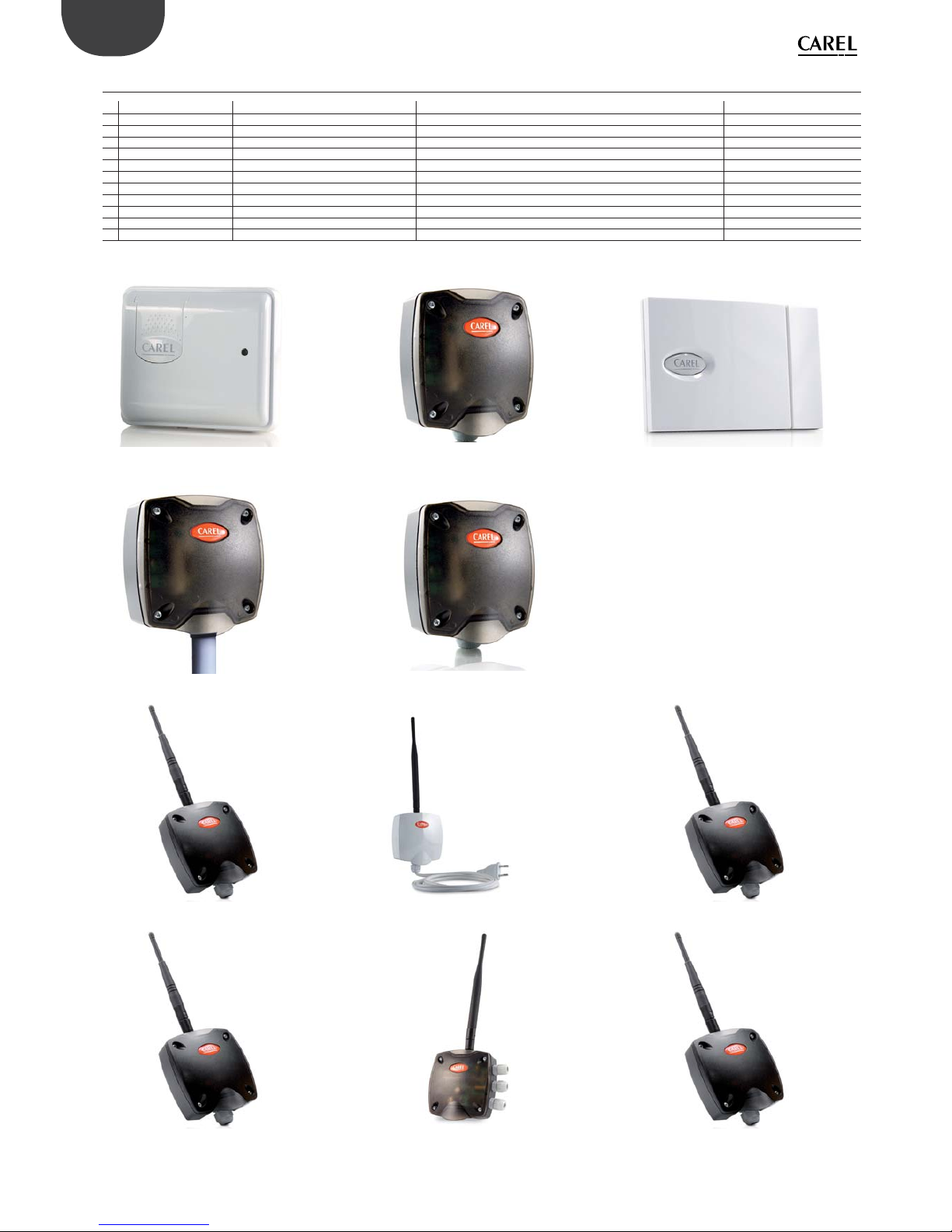
1.2 Codes
Code Model Features Power supply
WS01U01M00 BP SE Sensor Temp. for showcases Battery
WS01W02M00 EP SE Sensor Temp for cold rooms or showcases Battery
(*) WS01G01M00 SA Sensor Room temp./humid. Battery
(*) WS01F01M00 SI Sensor Temp./humid./lux for industrial use Battery
(*) WS01E02M00 CI Pulse Counter Pulse counter for energy modules Battery
WS01AB2M20 AP Access Point ZigBee – RS485 Modbus® Access Point 12-24 Vac/dc
WS01RC1M20 RO Router ZigBeewireless repeater 12-24 Vac/dc
WS01VB2M10 EP1 Router-Sensor Repeater with temp. sensor 12-24 Vac/dc
WS01RB2M20 RB Router-Bridge Repeater with RS485 Modbus® bridge 12-24 Vac/dc
(*) WS01HO2M20 RA Router-Actuator Repeater with I/O module - thermostat 12 Vac/dc
(*) WS01NO2M20 RC Router-Pulse Counter Repeater with Pulse counter (energy modules) 12-24 Vac/dc
(*) available soon
Tab. 0.a
BP SE Sensor EP SE Sensor SA Sensor
SI Sensor Pulse counter CI
Access point RO Router EP1 Router- sensor
RB Router-Bridge RA Router-Actuator RC Router- pulsecounter
Fig. 1.a

9
ENG
“Wireless probes” +0300030EN - rel. 1.0 - 16.07.2010
1.3 Terminology
Wireless
Wireless means “without wires”, in contrast to the term wired.
Wireless network
Communications system (series of devices, appliances, methods and
protocols) for the transmission of information via radio, typically radiofrequency technology used instead of wired connections, making the systems
particularly exible.
ZigBee™
Zigbee™ is a set of speci cations based on the IEEE-802.15.4 standard for
the creation of Wireless Personal Area Networks (WPAN). Comparable in
some ways to Bluetooth, it stands out for its very low power consumption
and the reduced cost of implementation, despite having a maximum data
transfer speed of 250 kbit/s. ZigBee™ devices, with compact dimensions and
low costs, are designed to work in dedicated self-organised networks (Mesh
networks) and are used in many elds.
1.4 Advantages of the wireless system
Advantages of a wireless network over a wired network
• Mobility of sensors;
• Easy to install and connect the devices;
• Coverage even where obstacles are present;
• Flexibility in the event of structural modi cations;
• Reduction in wiring costs;
• Robustness.
The advantages of wireless networks can overcome some of the intrinsic limits
in wired systems. Typical network infrastructure features a wired backbone
with wireless access.
Advantages of ZigBee™
• Standard technology;
• Reduced costs;
• Can be used globally;
• Reliable;
• Supports a large number of nodes;
• Easy con guration;
• Long battery life;
• Secure data transmission.
Distance
ConsumptionVelocity
Fig. 1.b
All brands and names shown in the diagram are registered trademarks and
the property of their respective owners.
10
ENG
“Wireless probes” +0300030EN - rel. 1.0 - 16.07.2010
Advantages of working at 2.4 GHz
Band of frequencies No. of channels Data parameters Use
Symbol rate Bit rate Mapping
868-868.6 MHz 1 20Kbit/s 20 Kbaud Binary Europe
902-928 MHz 10 40Kbit/s 40 Kbaud Binary North America
2.4-2.4835 GHz 16 250Kbit/s 62.5 Kbaud 16-ary orthogonal Worldwide
The band centred around 2.45 GHz (used in the wireless sensor system for
refrigeration) is the only one that can be used all over the world, without
needing to apply for special licenses. In addition, the ISM band (Industrial,
Scienti c and Medical) exploits the full potential of the standard, that is,
can use 16 transmission channels with a bit rate of 250 kbit/s.
Types of nodes
ZigBee™ Access Point - Co-ordinator and Gateway;
- Must be available and on in every network
- Coordinates the creation of the network;
ZigBee™ Router;
- Participates in the delivery of the messages, and must always be on;
- Available in Router-Bridge version for extending a wired local network
(for a list of approved controllers, see chapter on the features of the
Router), and EP1 Router-Sensor version.
ZigBee™ End-Device (sensors);
- Node with limited wireless functions;
- Low power consumption;
- Low cost;
For data communication with the Access Point, the end device uses a “parent”
for e ective wireless transmission; this may be a Router or the Access Point
itself.
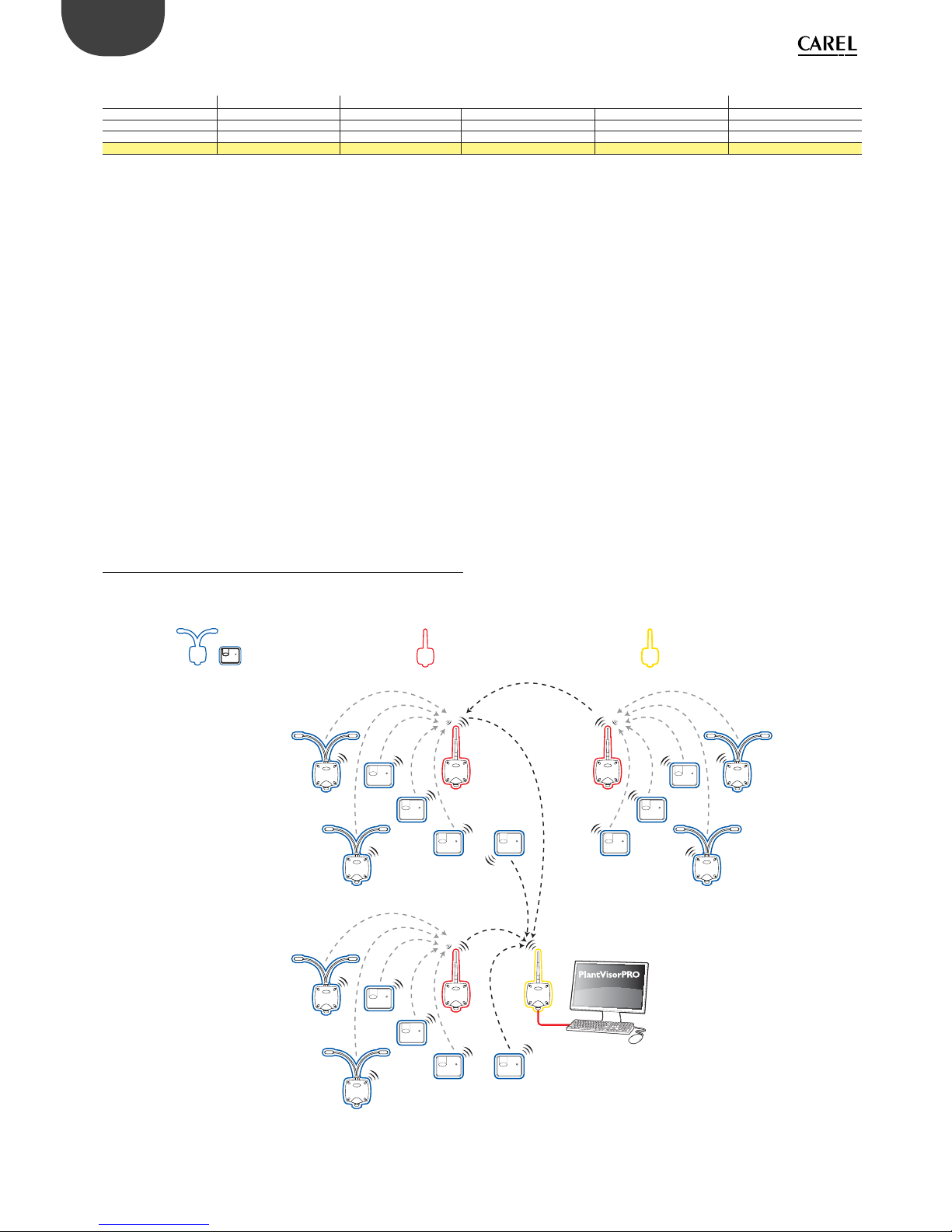
1.5 Type of Carel wireless network (MESH)
Legenda:
ZigBee» End-Device:
Sensors BP and EP (S)
ZigBee Router-Bridge (R)
ZigBee Coordinator -
Access point (AP)
RS 485 ModBus
S
S
S
S
S
S
R
R
S
S
S
S
S
R
S
S
S
S
S
S
AP
Fig. 1.c
Tab. 0.b

11
ENG
“Wireless probes” +0300030EN - rel. 1.0 - 16.07.2010
Example of a Mesh network
The MESH layout, used in the wireless sensor system for refrigeration between
coordinator nodes (access points) and router-bridge devices, ensures a high
tolerance to faults, as if one sensor loses wireless communication, the radio
signal still manages to nd an alternative route to reach the destination.
R
AP
RS 485 ModBus
R
R
Fig. 1.d
1.6 General features of the system
Maximum distance between Access Point/Router and Sensors in open eld
(outdoors): 100 m.
Maximum distance between Access Point/Router and Sensors with eld of
sight (indoors): around 30 m (inside rooms and built-up areas).
Transmission frequency: selectable from 2405 to 2480 MHz.
Number of channels available: 16.
Transmission power:
• Access Point 0 dBm
• Router 230Vac +10 dBm
• Router Bridge 0 dBm
• EP1 Router-Sensor +10 dBm
• RA Router-Actuator +3 dBm
• Router-Pulse Counter +10 dBm
• BP SE Sensor +3 dBm
• EP SE Sensor +3 dBm
• SA Room Sensor +3 dBm
• SI Industrial Sensor +3 dBm
• CI Pulse Counter +3 dBm
Wireless protocol: ZigBee™ without interoperability.
Standard: 802.15.4.
Reception sensitivity:
• Access Point -92 dBm
• Router SE 230Vac -97 dBm
• Router Bridge -92 dBm
• Router EP probe1 -97 dBm
• RA Router-Actuator -95 dBm
• Router-Pulse Counter -97 dBm
• BP SE Sensor -95 dBm
• EP SE Sensor -95 dBm
• SA Room Sensor -95 dBm
• SI Industrial Sensor -95 dBm
• CI Pulse Counter -95 dBm
For battery powered devices:
• Maximum current for battery powered devices only: 35 mA, in transmission.
• Current in standby: 1 µA.
Maximum HOP levels: 7 (hops).
Maximum number of wireless network devices:
• 30 for each Access Point (with 1 Router up to 60 units);
• 16 Routers directly connectable to the Access Point up to a maximum of 60
devices on the same network;
• 16 Router directly connectable to each Router up to a maximum of 60
devices on the same network;
Maximum number devices on Modbus® RS485 network:
• 7 Access Point;
• 111 Sensors;
• 60 Routers, max 48 of which monitored by the supervisor;
• On Modbus network in combination with other devices up to max 247
units.
1 234567
R
R
R
R
R
R
R
Access point
Router-Bridge
Max 60 sensors
Fig. 1.e
1.7 Using the Router
When does the Router need to be installed?
The Router is required whenever a direct connection is not possible between
the Access Point and the Sensor; this may occur when:
• The distance between Access Point and Sensor is greater than 30 m MAX
with visibility between the instruments.
• There is no visibility between the Access Point and the Sensor, and/or
there is shielding infrastructure that reduces the wireless communication
distance.
• In addition, the Router is required if the number of Sensors managed
exceeds 30 devices.
In addition, this is used to improve the reliability of the wireless connection,
the Router network can in fact nd an alternative path if one of the direct
connections between the sensors and the access point fails.
Recommended:
Up to 15 sensors 1 Router;
from 16 to 30 sensors 2 Routers;
from 31 to 45 sensors 3 Routers;
from 46 to 60 sensors 4 Routers.
1.8 General notes
The radio range of the devices is around a hundred metres in an open eld,
that is, without any obstacles.
In a closed eld the range varies signi cantly based on the type of environment
and the surrounding objects (shelves, furniture, metal walls etc.).
Thick partition walls or reinforced ceilings and oors may represent impassable
obstacles.
The ideal position of the devices, especially the routers, often cannot be
de ned theoretically but must be found by trial and error in the actual
installation.
Serial address assignment is valid for all devices
Make sure not to assign the same serial address ID to two devices in the same
wireless network.

12
ENG
“Wireless probes” +0300030EN - rel. 1.0 - 16.07.2010
1.9 Reference standards
The Carel wireless sensors have been tested in accordance with the following
standards:
INDUSTRIAL ENVIRONMENT
EN61000-6-4, EN61000-3-2, EN61000-3-3, EN61000-6-2
ETSI EN 301 489-17 V1.2.1, ETSI EN 301 489-1 V1.4.1
RES., COMM. AND LIGHT IND. ENVIRONMENT
EN61000-6-3; EN61000-3-2, EN61000-3-3; EN61000-6-1
Compliant with EN 13485 (Instruments for measuring the temperature of
foodstu s)
1.10 Battery life
Transmission time in min. Sensor battery life in years
13
55
10 8
15 8
Tab. 0.cTab. 1.c
The battery life is purely indicative and depends on the cycle transmission
time set and the quality of the wireless connection. If the device does not
communicate correctly with the Access Point (distance or interference
problems) battery life will be reduced due to the continuous attempts to
restore connection to the Access Point/Router.
1.11 List of sensor system variables
(alphabetical order)
Name
Description
ADD_HIGH_T_DELAY If when a high temperature is measured the “door open” or
“defrost in progress” signals are present, the device delays
the alarm by the value set for ADD_HIGH_T_DELAY (HR12).
ALM_BATTERY Provides the at battery signal (1 if < 2800 mV).
ALM_GENERAL Provides a general sensor fault signal.
ALM_LONG_DEFROST Provides the alarm status for the Defrost input (1=Alarm);
ALM_PROBE_1 Temperature measurement alarm on probe 1. This may
be caused by a value outside of the maximum range or
by the probe not connected correctly (open or shortcircuited).
ALM_PROBE_2 Temperature measurement alarm on probe 2. This may
be caused by a value outside of the maximum range or
by the probe not connected correctly (open or shortcircuited).
AP_RX_RADIO_LEV Wireless signal level received from the Access Point for the
sensor (see note 1).
AUTO_DELAY De nes a delay time for the evaluation of the type of
showcase when auto-con guration mode is enabled.
AVERAGE_PARAM Weight for calculating the average, as per the formula with
weight M.
AVG_TEMPERATURE Temperature value calculated as the weighted average (in
tenths of a degree °C).
BATTERY_CHARGE De nes the residual charge, counting power consumption
corresponding to the operations e ectively carried out.
This can be used, together with the BATTERY_LEVEL value,
for a more complete evaluation of battery charge status.
Full charge mAh.
BATTERY_LEVEL Battery voltage value (mV). The rated value is 3600 mV,
below 2800 mV the battery is discharged.
CMD_PASSW_1 Only used by con guration systems.
CNT_REJOIN Wireless network parameter for internal use
DEFROST_ALM_DELAY Delay time (wait) in minutes before Defrost alarm signal
DEFROST_POL Logical state of the defrost input based on the electrical
state of the contact (open or closed).
DOOR_POL Logical state of the door input according to the electrical
state of the contact (open or closed).
EN_AUTO_CONF Enable automatic con guration mode (1= enabled).
EN_CMD_PW Only used by con guration systems.
EN_DI_DEFROST Enable/disable defrost digital input.
EN_DI_DOOR Enable/disable door digital input.
EN_HI_TEMP_ALM Enable the high temperature alarm signal (if=1), otherwise
the alarm is not measured/signalled. Used for both probes
1 and 2.
EN_SCAFFALE Selects the medium temperature shelf display case
(1=shelf)
FW_VERSION FW revision
HI_TEMP_ALM_1 Provides the status of the high temperature alarm for
probe 1
HI_TEMP_ALM_2 Provides the status of the high temperature alarm for
probe 2
HI_TEMP_TRESHOLD High temperature signal thresholds (in tenths of a degree
°C)
HI_TEMP_TRESHOLD_1
High temperature signal threshold for probe 1. Can be set
in tenths of a degree centigrade
HI_TEMP_TRE-
SHOLD_2
High temperature signal threshold for probe 2. Can be set
in tenths of a degree centigrade
HIGH_TEMP_DELAY Delay (waiting) time in minutes before the high tempe-
rature alarm is actually signalled. Used for both probes 1
and 2
ID_SER_ADDR Sensor serial address, set using the rTM SE handheld or by
switch. Used as the sensor identi er
IN_1_STATUS Status of digital input 1
IN_2_STATUS Status of digital input 2
LAST_RX_DELAY Wireless network parameter for internal use
LO_TEMP_ALM Provides the status of the low temperature alarm
LO_TEMP_ALM_1 Provides the status of the low temperature alarm for probe
1
LO_TEMP_ALM_2 Provides the status of the low temperature alarm for probe
2
LO_TEMP_TRESHOLD Low temperature signal threshold (in tenths of a degree
°C). Signal without delays.
LO_TEMP_TRE-
SHOLD_1
Low temperature signal threshold for probe 1. Can be set
in tenths of °C. Signal without delays
LO_TEMP_TRE-
SHOLD_2
Low temperature signal threshold for probe 2. Can be set
in tenths of °C. Signal without delays
MAC_ADDR_0 Unique 32 bit unit identi er, LSB. Used to uniquely identify
each sensor
MAC_ADDR_1 Unique 32 bit unit identi er, MSB. Used to uniquely identi-
fy each sensor
MACHINE_CODE Peripheral identi er for the supervisor
MIN_RSSI_LEVEL Wireless network parameter for internal use
MIRROR_IS Wireless network parameter for internal use
MODE_AUTO_TRESH De nes a threshold in °C below which the procedure
for the automatic recognition of the type of showcase is
activated.
MODE_PARAM De nes the values to be assigned or auto-assigned for the
identi cation of the e ective operating mode. For each
of the four modes, the associated parameters can be set
separately, and are loaded when the mode is activated
NETWORK_ID Wireless network parameter for internal use
OFFS_TEMP Temperature measurement o set, within a maximum of
±9.9 °C.
OFFS_TEMP_1 Calibration o set for probe 1, within a max of ±9.9 C;
OFFS_TEMP_2 Calibration o set for probe 2, within a max of ±9.9 C;
RX_MESSAGE_CNT Wireless network parameter for internal use
RX_MSG_LEVEL Wireless signal level received for the sensor in dBm+100
(see note 1).
TEMPERATURE Instant temperature value (in tenths of a degree °C).
TEMPERATURE_1 Provides the temperature values measured by probe 1. The
temperature reading is in the range from -50°C to +90°C;
TEMPERATURE_2 Provides the temperature values measured by probe 2. The
temperature reading is in the range from -50°C to +90°C;
TIME_STAMP Value expressed in hours:minutes associated with the last
wireless data transmissions received. This can be used to
synchronise the measurements from di erent units with
the same clock. Variable added by the Access Point for
each sensor.
TRANSM_CYCLE De nes the wireless data transmission time to the Access
Point. The value is set in seconds, but must correspond
(rounded o ) to a multiple of 60, thus in minutes (see
note 2).
TX_MESSAGE_CNT Wireless network parameter for internal use
TX_POWER Wireless network parameter for internal use
Tab. 0.dTab. 1.d
Note:
• The two values provide an indication of the wireless signal levels seen from
the sensor and the Access Point. The minimum value must be greater than
8, for medium reception from 15 to 30, and excellent for values greater than
30.
• To maximise battery life, the number of transmissions should be limited to
the minimum possible.

13
ENG
“Wireless probes” +0300030EN - rel. 1.0 - 16.07.2010
2. BP SE SENSOR BUILTIN PROBE
The BP SE Sensor is designed to be positioned directly inside the showcases, tted using its own fastening bracket. The rear features
metal shielding that, combined with the thermal insulation inside the shell, prevents the formation of frost at the rear of the sensor,
and consequently better thermal insulation from the wall.
Fig. 2.a
2.1 Functions implemented and supervisor
variables available
• Instant temperature measurement performed every minute.
• Measurement ltering with weighted average based on parameter setting
for product temperature simulation.
• Data transmission at settable intervals, in minutes (the parameter a ects
battery life).
• Monitoring of temperature thresholds for high temperature (HACCP) or low
temperature (product freezing) alarm signals.
• Automatic mode with preset parameters according to the showcase/
display case (normal, low temperature or open shelf).
• Local mode for Clean showcase status signal. Activating the Clean button
disables the high temperature alarms.
• TimeStamp for recording the instant measurement, expressed in hh:mm.
• Battery level in mV and residual charge in mAh.
• Wireless signal level in dBm +100 (less than 8=low, 15-30=medium, higher
than 30=excellent);
• Temperature alarm status related to the high and low thresholds.
2.2 Sensor con guration
The sensor is supplied with the address ID set to 127 and cannot be used with
the default ID; the range of available addresses is from 16 to 126. To assign the
ID use the rTM SE handheld accessory. For details on the address assignment
procedure see the instructions in the chapter on the rTM SE handheld further
on.
In emergency situations a new ID can be assigned (limited to the range from
16 to 99) using a magnet (e.g. magnetic screwdriver Carel code 0000000722),
as follows:
1. Position the magnet on SW1, holding it in position when the green LED
comes on;
2. The following will be shown in sequence:
- Green LED ON for 2 to 3s then OFF for 3 to 4s;
- Orange LED ON for 3 to 4s;
- Remove the magnet when the LED switches o ;
- After a few moments the LED comes on yellow for 1s. This indicates
that programming procedure is active (if no actions are performed,
programming mode ends after 4/5 s, indicated by a double yellow ash,
leaving all the settings unchanged);
3. Move the Clean switch SW2 up and down a number of times equal to the
tens of the serial address being set (e.g. 10, once – 50, ve times). Each
time switch SW2 is moved up the red LED comes on for 1 s, (con rming
stimulation);
4. Subsequently use the magnet to stimulate switch SW1 a number of times
equal to the units (e.g. 1, once – 5, ve times). Each time the magnet moves
over the switch the green LED comes on for 1 s (con rming stimulation).
The order is not important (tens or units rst);
5. After 4/5 s the sensor exits the procedure, with the yellow LED ashing
twice (indicating the end of serial address setting mode);
6. Subsequently the sensor shows the serial address using a sequence of
ashes repeated cyclically three times. To read the codes, see the chapter
“Display sensor serial ID” further on.
7. Moving switch SW2 up interrupts the cycle;
The sensor address has been set and it’s ready to be bound to an Access Point.
The procedure can be performed before or after binding to the Access Point.
Make sure not to assign duplicate serial addresses, also considering other
devices in the network. For further information and explanations on the
procedure, see the rTM SE system installation guide.
Binding procedure
Binding is a special procedure used to associate the sensors with the Access
Point. Once completed, the sensors will send the temperature data measure
wirelessly only to the Access Point de ned as its parent. Following this, the
Access Point will forward the data to the Modbus® RTU RS485 serial network.
The binding procedure requires the activation of the Access Point wireless
network and activation of the con guration switch SW1 using a magnet (see
the gure), done by passing the special magnet over magnetic switch SW1
for a few seconds. The LEDs will come on in sequence: green (1s), yellow (4 to
5s), green (6 to 10s). If at the end of the sequence the red LED ashes brie y (1
to 2s), binding with the Access Point has failed. If the operation is successful,
successively activating switch SW1 will start manual data transmission,
signalled by the green LED ashing quickly twice.
If the automatic or manual data transmission fails, the red LED will ash brie y
after the green LED comes on.
After this operation the sensor will start sending data on the temperature
measured, in the time interval set by parameter. Check that the LED comes on
for a few seconds at regular intervals, based on the transmission time set for
parameter (HR_01 TRANS_CYCLE). When the operation has ended close the
wireless network on the Access Point. The wireless network can be opened
and closed using the rTM SE handheld accessory.
Display sensor serial ID
To check the sensor serial address, proceed as follows:
• Move switch SW2 (CLEAN) up, stimulate SW1;
• The LED starts ashing in sequence. Count the number of the ashes to
calculate the hundreds (Yellow), tens (Green) and units (Red). Removing
the magnet or lowering the button exits the display probe serial address
procedure.
• Move switch SW2 back down.
Yellow Red Green
X 100 X 10 X 1
Hundreds Tens Units
Tab. 2.a
Example
0 yellow ashes 5 red ashes 7 green ashes
057
Sensor address ID=57
Tab. 2.b
Resetting the sensor (maintaining the serial address)
The reset procedure is required when the sensor needs to be moved and
associated with another wireless network (di erent Access Point). This
operation may be required to recon gure the sensor in a di erent wireless
network. The value of the serial address remains the same, and after a new
binding operation the sensor is reactivated in the wireless network. To reset
the sensor, proceed as follows:
1. Place the magnet near magnetic switch SW1 (the green LED will come on);
2. Hold the magnet in place until the green LED goes o and the yellow LED
comes on (after approx. 6 to 10 sec.);
3. When the yellow LED comes on, move the magnet immediately away
from the sensor and check that the LED ashes quickly before going o
(RESET COMPLETE).
To check that the sensor has been reset, proceed as follows:
1. Make sure the Access Point wireless network is closed (L1 ashing slowly
1s);
2. Stimulate switch SW1 on the sensor with the magnet;
3. Check that LEDs come on in the following sequence:
- green LED (1 s);
- yellow LED (4 to 5 s);
- green LED (15 s);
- red LED (1 s);
Make sure that there are no sensors with the same serial address in the new
network. If this is the case, assign a new serial address.

14
ENG
“Wireless probes” +0300030EN - rel. 1.0 - 16.07.2010
RESET sensor and assign default serial address (=127)
To restore the sensor serial address to the default value, proceed as follows:
1. Place the magnet near magnetic switch SW1, the green LED will come on.
2. Hold the magnet in position until the green LED goes o and the yellow
LED comes on (after approx. 6 to 10 s);
3. Immediately remove the magnet from the sensor and at the same time
move the CLEAN switch (SW2) up, making sure the yellow LED ashes a
few times.
4. Move the CLEAN switch to the OFF position and make sure the yellow LED
completes a rapid sequence of ashes (RESET COMPLETE);
Otherwise repeat the procedure.
To check that the sensor has e ectively been reset, proceed as follows:
1. Make sure the Access Point wireless network is closed (L1 ashing slowly
1 s);
2. Stimulate the switch SW1 with the magnet;
3. Check that LEDs come on in the following sequence:
- green LED (1 sec.);
- yellow LED (4 to 5 sec.);
- green LED (15 sec.);
- red LED (1 sec.);
Completing the reset procedure and assigning the default serial address
returns the sensors to the same status as a new device.
To assign a new address, repeat the serial address assignment procedure.
Note:
1. The sensor can only be reset if it has already been bound to an Access
Point.
2. Note that, after resetting the sensor, the number of devices set for the Access
Point remains unchanged. Realignment will occur after a maximum of around
2 hours.
Meaning of the switches and LED signals
CLEAN
SW2
SW1
Led
NTC
Fig. 2.b
Key:
SW1 Internal magnetic con guration switch (above the LED, labelled).
Can be activated by external magnet
SW2 Magnetic CLEAN switch (open = CLEAN MODE)
LED Two-colour red/green (yellow if both are on)
NTC Located inside the case in thermal contact directly with the front wall
The following table describes how the LEDs ash whenever SW1 or SW2 are
stimulated or when data is transmitted.
Action LED sequence (times in s.) Meaning of the signal
Stimulating SW1 /
data transmission
Green ashing (approx. 1s) Communication with
Access Point occurred
correctly
Stimulating SW1 /
data transmission
Green ashing (approx. 1s) red
ON (approx. 0.5s)
Communication with
Access Point NOT
successful
Stimulating SW1 /
data transmission
Green ashing (approx. 1s) OFF
(approx. 1s) red ON (approx.
0.5s)
Communication with
Access Point NOT
successful
Stimulating SW1
Green ON (approx. 1s)yellow
ON (4..5s) green ON (approx.
15s) red ON (approx. 1s)
BP SE Sensor in Reset
status
Binding with Access
Point failed
Stimulating SW1
Green ON (approx. 1s)yellow
ON (4..5s) green ON (6..10s)
OFF
Binding with Access
Point successful
Open CLEAN cover
(SW2)
Red ON (approx. 1s)green ON
(approx. 0.5s)
CLEAN mode activated
Reset procedure
Green ON (approx. 2..3s) OFF
(approx. 6..7s)yellow ON
(approx. 2..3s)OFF (approx.
1s)yellow ashing (approx. 1s)
Sensor being reset
Reset procedure
and assign default
serial address
Green ON (approx. 2..3s)OFF
(approx. 6..7s)yellow (approx.
2..3s) yellow ashing (depends
on when the CLEAN door
is closed)OFF (approx.1s)
yellow ashing (approx. 1s)
Reset sensor plus return
serial address to default
value
Tab. 2.c
Note: the LED is two-colour, red and green, which becomes yellow when both
LEDs are on at the same time. There may be di erent shades of yellow due to
di erent tolerance in the brightness of the red and green LEDs.
2.3 Sensor activation
When the sensor is put in SLEEP mode using the rTM SE handheld during
the procedure to assign the serial address (no transmission-minimum power
consumption), the sensor is e ectively in standby; nothing is transmitted
until movement of the CLEAN switch is activated (sleep status). Activation is
not reversible, and the sensor will send the temperature measured every 16
min (default value) if the Access Point that the sensor has been bound to is
switched on.
To exit sleep mode, proceed as follows:
• Power up the Access Point;
• Move the CLEAN switch to the ON position (SW2);
• Make sure the red LED comes on for a few seconds.;
• When the red LED comes on immediately the CLEAN switch to the OFF
position;
• The LED on the sensor remains on until it has connected to the Access Point.
If the operation fails, the sensor returns to sleep mode, if however it’s successful
normal operation will resume, with data being sent every 16 min.
Check operation by stimulating the sensor.
Resetting the sensor in sleep mode
If the sensor needs to be reset when in sleep mode (Access Point network
parameters forgotten), proceed as follows:
• Move the CLEAN switch to the ON position (SW2);
• Wait for the red LED to come on;
• Stimulate SW1 continuously while the red LED remains on.
• Keep SW1 stimulated until the LED ashes (yellow) ;
• Remove the magnet from SW1 and move switch SW2 back down.
• Reset completed.
Led
Posizione switch OFF
Switch OFF position
Posizione switch ON
Switch ON position
Fig. 2.c
Parameters and functions
The BP wireless sensor reads the temperature and manages the associated
alarms at one minute intervals.
The data is then transmitted at the intervals set by parameter, according to the
application and the expected battery life. The sensors work most of the time in
low power mode, so as to save battery power. They are activated to make the
measurements and send the data at the preset time.
Activate switch SW1 to send the sensor data manually, or check the connection.
The CLEAN button is used to set cleaning status or deactivate the showcase,
thus disabling the high temperature alarms.
When returning from CLEAN mode, the high temperature alarms are disabled
for a time equivalent to the auto-con guration cycle (AUTO_DELAY).

15
ENG
“Wireless probes” +0300030EN - rel. 1.0 - 16.07.2010
The sensor takes individual instant temperature measurements, however can
also provide a weighted average, used to better approximate the product
temperature. The logic for the alarms and all the other functions depends on
the instant temperature measurement.
Wireless communication is activated automatically in the following situations:
• moving the CLEAN mode switch (SW2);
• stimulating the magnetic switch (SW1).
In all other cases, data transmission is de ned by the set transmission cycle.
Note:
• The temperature measurement, with the update of the instant and average
values, is performed at 1 minute intervals.
Important: the value is displayed on the supervisor after the set sensor
transmission time .
The average temperature value is calculated using the following formula:
Temp_AVG = (Temp_AVG-1 * (M - 1) + Temp_Ist) / M
Where:
• Temp_AVG-1 Previous average temperature value
• Temp_Ist Instant temperature measurement
• M Average weight (= AVERAGE_PARAM)
The average function also introduces an average measurement delay with a
time constant equal to the average weight value (in minutes).
High temperature alarm function:
Alarm delay
HIGH_TEMP_DELAY
Alarm delay
HIGH_TEMP_DELAY
EN_HI_TEMP_ALM
LO_TEMP_ALM_1
HI_TEMP_ALM_1
Reset counter alarm
Start counter alarm delay
HI_TEMP_TRESHOLD
LO_TEMP_TRESHOLD
Temp. °C
Time
Alarm ON
Fig. 2.d
• When the threshold is exceeded, the alarm is signalled only if this persists
for a time greater than the delay set;
• If the temperature returns within the threshold before the delay time, the
accumulated count is reset;
• The alarm is reset instantly when the temperature returns within the
threshold.
Default values for the modes settable for the MODE_PARAM
parameter
MODE 0
Generic use
MODE
1LOW
showcases
MODE
2MED
showcases
MODE 3MED
shelf cases
High temp. threshold
-15 °C -15 °C +10 °C +8 °C
Low temp. threshold
-40 °C -40 °C -2 °C -2 °C
HACCP delay 180 min. 120 min. 120 min. 120 min.
Average weight 1 (Instant) 16 (16 min.) 8 (8 min.) 12 (12 min.)
Tab. 2.d
Automatic con guration procedure
The automatic recognition procedure is used to recognise the type of
showcase and consequently con gure the parameters for the showcase
that the sensor is installed on. The automatic recognition cycle is activated (if
enabled by EN_AUTO_CONF):
• When the temperature falls below the threshold MODE_AUTO_TRESH;
• When returning from CLEAN mode, closing the switch;
• When a previous cycle is completed.
When the AUTO_DELAY time has elapsed, if the following conditions are true:
• Final temperature rise less than 1°C/h;
• Final temperature within a xed band of temperatures for the various types
of showcase:
- medium temp. showcases = from -2°C to + 6°C
- low temp. showcases = less than -10°C.
The MODE_PARAM parameter is given the new value corresponding to the
type of showcase and the associated values for the alarm thresholds, alarm
delay and average weight are loaded;
Note:
• In the event of increases in temperature for low temperature showcases,
the recognition procedure is disabled for 3 times the value of AUTO_DELAY,
to avoid false recognitions.
• The temperature alarms are always enabled, if MODE_PARAM and
consequently the associated parameters are changed, the alarm logic
depends on the new parameters.
• The parameters associated with each mode (0-3) are saved separately and
permanently, and are loaded automatically when the mode is changed.
• The values of the parameters associated with the mode must be set (by the
supervisor) making sure that MODE_PARAM does not change, otherwise
the values transferred may be ignored.
2.4 Technical speci cations
Power supply 3.6V 2500 mAh lithium battery, “AA” size
Maximum power input 100 mW
Battery life in normal operating
conditions
From 3 to 8 years, depending on the transmission time set.
(CAREL is not responsible for the speci ed
battery life)
Radio frequency speci cations Frequency: selectable from 2405 to 2480 MHz
Power transmitted: 0dBm
Wireless protocol: ZigBee
Operating conditions -40T50°C
Storage conditions -20T60°C
humidity range: <80% RH non-condensing
Precision of temperature measurement
± 1 °C -10T30°C;
± 2 °C -30T40°C
Response time to temperature
variations
> 20 minutes
Compliant with EN 13485
Index of protection against atmospheric agents
IP65
Classi cation according to protection against electric shock
Can be integrated into class I or class II
appliances
Environmental pollution Normal
PTI of insulating materials 250 V
Period of stress across the insulating parts
Long
Category of resistance to heat
and re
category D (box and cover)
Immunity against voltage surges category 1
Software class and structure Class A
Disposal observe local legislation for the disposal of
electrical material
Product code WS01U01M0 - Wireless sensor ver. BP SE IP65
-40 to 50°C
Accessories WS00BAT000 Battery
WS00B01000 Plastic case only
0000000722 Magnet for activating SW1
Tab. 2.e

16
ENG
“Wireless probes” +0300030EN - rel. 1.0 - 16.07.2010
2.5 List of parameters and variables, BP SE
Sensor
Below is the table of supervisor parameters for the BP SE Sensor.
Variable Index Name Description Def. Min Max UoM “ Type R/W”
HR0 ‘CMD_PASSW_1’ ‘Command Password (1)’ 0 0 65535 - R/W
HR1 ‘TRANSM_CYCLE’ ‘TX data cycle time’ 960 60 3600 sec R/W
HR2 ‘HI_TEMP_TRESHOLD’ ‘Threshold high Temp.’ -150 -400 500 0,1°C R/W
HR3 ‘LO_TEMP_TRESHOLD’ ‘Threshold low Temp.’ -400 -400 500 0,1°C R/W
HR4 ‘HIGH_TEMP_DELAY’ ‘Delay High Temp. Alarm’ 120 0 254 min R/W
HR5 ‘MODE_AUTO_TRESH’ ‘ Threshold Auto Temp.’ 120 0 500 min R/W
HR6 ‘AVERAGE_PARAM’ ‘Parameter Avg-readings’ 16 1 60 - R/W
HR7 ‘AUTO_DELAY’ ‘Delay for AUTO-Con g’ 120 2 254 min R/W
HR8 ‘MODE_PARAM’ ‘Par. MODE for cabinets’ 1 0 3 - R/W
HR9 ‘OFFS_TEMP’ ‘O set Temperature Measure’ 0 -99 99 0,1°C R/W
HR10 ‘MIN_RSSI_LEVEL’ ‘Minimum rssi level counted (internal use)’ 0 0 99 - R/W
HR11 ‘CNT_REJOIN’ ‘Max counter value before rejoin (internal use)’ 30 1 255 - R/W
IR0 ‘MACHINE_CODE’ ‘Unit type - machine code’ 63 - - - R
IR1 ‘FW_VERSION’ ‘Firmware version (Major/Minor)’ 2051 - - - R
IR2 ‘TX_MESSAGE_CNT’ ‘Total Number of TX radio messages’ 0 0 65535 - R
IR3 ‘RX_MSG_LEVEL’ ‘Radio signal Level’ 0 0 100 dBm+100 R
IR4 ‘ID_SER_ADDR’ ‘Carel_ID Serial_Address DIP-SW value’ - 16 127 - R
IR5 ‘BATTERY_LEVEL’ ‘Battery Level’ - 0 3600 mV R
IR6 ‘AVG_TEMPERATURE’ ‘Temperature average Value’ - -500 1000 0,1°C R
IR7 ‘ TEMPERATURE ‘ ‘ Temperature Value’ - -500 1000 0,1°C R
IR8 ‘BATTERY_CHARGE’ ‘Counter battery remaining charge’ - 0 65535 - R
IR9 ‘MAC_ADDR_0’ ‘Unit unique identi er Mac-Address LSB’ - 0 65535 - R
IR10 ‘MAC_ADDR_1’ ‘Unit unique identi er Mac-Address MSB’ - 0 65535 - R
IR11 ‘LAST_RX_DELAY’ ‘Time from last AP Rx message’ - 0 65535 - R
IR12 ‘RX_MESSAGE_CNT’ ‘Counter - AP Rx messages’ - 0 65535 - R
IR13 ‘TIME_STAMP’ ‘Time stamp for Temp. readings (100*hour+minute) ‘ - 0 2359 R
IR14 ‘AP_RX_RADIO_LEV’ ‘Radio Lev. for AP Rx messages’ - 0 100 dBm+100 R
IR15 ‘NETWORK_ID’ ‘Net work address ‘ - 0 65535 - R
IR16 ‘MIRROR_IS’ ‘Mirror Input Status (internal use)’ - 0 65535 - R
CS0 ‘EN_CMD_PW’ ‘Trig. PWD (internal use)’ 0 0 1 - R/W
CS1 ‘EN_HI_TEMP_ALM’ ‘Enable High Temp. Alarm’ 1 0 1 - R/W
CS2 ‘EN_AUTO_CONF’ ‘Enable auto con guration MODE’ 0 0 1 - R/W
CS3 ‘EN_SCAFFALE’ ‘Type of cabinet ( 1= sca ale)’ 0 0 1 - R/W
IS0 ‘ALM_BATTERY’ ‘Battery Alarm’ - 0 1 - R
IS1 ‘ALM_GENERAL’ ‘Unit General Alarm’ - 0 1 - R
IS2 ‘ALM_PROBE_1’ ‘Temperature sensor Alarm’ - 0 1 - R
IS3 ‘HI_TEMP_ALM_1’ ‘High Temperature Alarm’ - 0 1 - R
IS4 ‘LO_TEMP_ALM_1’ ‘Low Temperature Alarm’ - 0 1 - R
Tab. 2.f
Key:
HR = Holding register
IR = Input register
CS = Coil Status
IS = Input Status

17
ENG
“Wireless probes” +0300030EN - rel. 1.0 - 16.07.2010
2.6 Installation notes
The sensor is installed on the bracket supplied as follows:
1. Fasten the bracket to the wall with two screws, supplied together with the
sensor, considering that the unit being installed is a radio device, and thus
taking the necessary precautions;
2. Couple the sensor to the bracket, making sure it clicks and locks into place.
N.B. To remove the sensor from the bracket, lift the release spring using a
suitable screwdriver and lift the sensor.
click
Fig. 2.e
2.7 Physical dimensions
7.527 83.9
71.634
SW1
SW2
NTC
LED
44
50
Fig. 2.f
2.8 Replacing the battery in the BP SE
Sensor
The case of the BP SE wireless sensor has been designed to provide high
protection. When opening the two plastic shells to replace the battery, the
locking catches may be damaged or break. Consequently, the spare battery
is supplied together with a new case. Take maximum care when removing
the electronic board from the old shell and placing it in the new one, so as to
not damage the electronic components. Make sure battery polarity is correct.
Remove the product label from the old case and place it on the new one.
Rules for disposing of the battery
Do not dispose of the product as municipal waste; it must be disposed of
through specialist waste disposal centres.
The product contains a battery that must be removed and separated from the
rest of the product.
Improper use or incorrect disposal of the product may negative e ects on
human health and on the environment.
The public or private waste collection systems de ned by local legislation
must be used for disposal.
In the event of illegal disposal of electrical and electronic waste, the penalties
are speci ed by local waste disposal legislation.
2.9 Application examples
Supermarket showcases
Fig. 2.g
Fig. 2.h
Example of supermarket layout and installation connections
RS 485 ModBus
Router/Bridge
Fig. 2.i

18
ENG
“Wireless probes” +0300030EN - rel. 1.0 - 16.07.2010
3. EP SE, SA, SI SENSORS AND CI PULSE COUNTER
3.1 Parameters and functions
The wireless devices read the temperature and manage the associated
alarms at intervals set by the transmission time parameter, according to
the application and the expected battery life. The sensors work most of the
time in low power mode, so as to save battery power. Press the button or
stimulate the magnetic switch to send the sensor data manually, or check the
connection.
3.2 Description of the acquisition process
The devices acquire all the values before sending their status to the Access Point.
Consequently, the device sampling interval is equal to the transmission time.
3.3 Device con guration
Select the desired network address using the 8 dipswitches (0=OFF; 1=ON) as
shown in the table. The possible sensor addresses are from 16 to 126.
Address
Dipswitch Notes
12345678
0..15 x x x x x x x x address not allowed (*)
16 0 0 0 0 1 0 0 0
17 1 0 0 0 1 0 0 0
18 0 1 0 0 1 0 0 0
19 1 1 0 0 1 0 0 0
20 0 0 1 0 1 0 0 0
...127 0 1 1 1 1 1 1 1 Reserved. Do not use
128,...199 1 1 1 0 0 0 1 1 address not allowed (*)
200...256 x x x x x x x x address not allowed (*)
Tab. 3.a
For the complete list see the table at the end of the manual.
(*) The address may be set however the device cannot connect to the Access
Point/Router. Pressing the button the LED ashes quickly in sequence to
indicate an invalid address.
EXAMPLE required sensor address setting 117:
Decimal value: 117
Conversion to binary notation:(MSB) 0111 0101 (LSB)
Reverse the value of the string (10101110) and assign dipswitches from (LSB)
1 to 8. (MSB).
Dipswitch
1 2 3 456 7 8
x x x xxx x x
0 0 0 010 0 0
1 0 0 010 0 0
0 1 0 010 0 0
1 1 0 010 0 0
0 0 1 010 0 0
0 1 1 111 1 1
1 1 1 000 1 1
x x x xxx x x
Tab. 3.b
This section provides all the information common to the devices whose serial ID is con gured by dipswitch. Refer to the speci c instructions for each device.
EP SE SA Sensor SI Sensor CI Pulse Counter
Fig. 3.a

19
ENG
“Wireless probes” +0300030EN - rel. 1.0 - 16.07.2010
3.4 Binding procedure
Binding is a special procedure used to associate the sensors with the Access
Point. Once completed, the sensors will send the temperature data measure
wirelessly only to the Access Point de ned as its parent. Following this, the
Access Point will forward the data to the Modbus® RTU RS485 serial network.
Before performing this operation, make sure that the sensor serial address has
been set.
After having opened the domain on the Access Point (see the instructions in
the chapter on the Access Point), proceed as follows on the sensor:
Remove the protection from the contact on the battery to power up the
device;
Check that the LED comes on for a few seconds with brief ashes.
Press the button once or activate the magnetic switch. Pressing it again
activates a procedure to check the quality of the wireless signal (see the
chapter “Analysing wireless signal quality”);
LED L1 on the sensor remains on until connection to the Access Point is
complete, ashing for around 10s, then L1, L2 and L3 ash together for a few
seconds (wireless network connection).
The procedure for analysing wireless signal quality then starts for around 1
minute. The following come on in sequence:
1. L1 Indicates wireless transmission has occurred;
2. L1-L2 Indicates the signal has been received by the Access Point;
3. L3 ashes from 1 to 3 times, based on the quality of the wireless signal;
- 1 ash, wireless connection with minimum signal strength;
- 2 ashes, wireless connection with medium signal strength;
- 3 ashes, wireless connection with excellent signal strength;
Button T1 is connected in parallel with the magnetic switch. The case does not
need to be opened to stimulate the sensor for communication
Note: if LED L1 ashes once instead of remaining on, it means that the sensor
has already been bound to an Access Point. In this case, reset the sensor (see
Resetting the devices)
The Access Point shows that connection has been made by LED L3 coming
on for around 1s., even if another node in the network is sending a message.
Check the con guration: the sensor will be correctly bound if whenever the
button is pressed or the magnetic switch is activated, the LEDs come on for a
1 min sequence.
• L1, on for 1s;
• L1-L2, on for 1s;
• L3, ashes from 1 to 3 times, based on the quality of the wireless signal;
- 1 ash, wireless connection with minimum signal strength;
- 2 ashes, wireless connection with medium signal strength;
- 3 ashes, wireless connection with excellent signal strength;
For the EP SE Sensor, in normal operation LED L1 ashes for 1s every 20s. In
general, for the other devices, the LED comes on whenever data is sent, and
consequently based on the device transmission time.
Important: the sensor binding operation may fail if:
- the distances are high and/or there is infrastructure that does not allow
communication between the devices (see the example of sensor S2 in Figure
4.c);
- the maximum limit of sensors allowed for the Access Point has been reached
(max 30). In this case, an additional Router-Bridge is needed for up to a
maximum of 60 sensors.
3.5 Resetting the sensor (unbinding)
The reset procedure is required when the sensor needs to be moved and
associated with another wireless network (di erent Access Point). This
operation may be required to recon gure the sensor in a di erent wireless
network. The value of the serial address remains the same, unless the
con guration dipswitches are moved. After a new binding operation the
sensor is reactivated in the wireless network. To reset the EP SE Sensor, proceed
as follows:
1. Remove the battery (press the button to discharge any residual energy in
the circuit) and replace the battery in its socket (LEDs L1, L2, L3 come on
at the same time, then ash quickly and switch o ).
2. Immediately after the LED have switched o (within a few seconds) press
button T1 until the pairs of LEDs L1-L3 and L2 ash alternately.
3. Release the button. LEDs L1, L2, L3 will ash brie y and then switch o .
To make sure the sensor has e ectively been reset:
1. Make sure the Access Point wireless network is closed (L1 ashes slowly
1s).
2. Press button T1 on the sensor and make sure LED L1 comes on and
remains on for around 20 sec.
WARNING: The sensor has been unbound (reset) and maintains the same
network address assigned.
To change the address, remove the battery, move dipswitches 1 to 8, and
replace the battery.
Note:
1. The sensor can only be reset if it has already been associated with an
Access Point;
2. Resetting the sensor does not delete the space reserved inside the Access
Point, which will continue to maintain the data saved inside. Note that,
after resetting the sensor, the number of devices set for the Access Point
remains unchanged. Realignment will occur after a maximum of around
2 hours.
Important: pay careful attention to avoid duplicate assignment of network
serial addresses, so as to avoid overlapping temperature values.
The sensor is supplied with the battery already tted, and with the positive
pole insulated by a protective lm; this must be removed after assigning the
network serial address.
3.6 General warnings
When replacing the battery, strictly observe the following instructions.
The battery may explode if replaced with another of an incorrect type. Dispose
of the used batteries according to the standards in force;
Install the sensor with the cable gland facing downwards;
Replacing the battery
Remove the cover, remove the battery, and replace with another of the same
type. Close the cover again.
Rules for disposing of the battery
Do not dispose of the product as municipal waste; it must be disposed of
through specialist waste disposal centres.
The product contains a battery that must be removed and separated from the
rest of the product.
Improper use or incorrect disposal of the product may negative e ects on
human health and on the environment.
The public or private waste collection systems de ned by local legislation
must be used for disposal.
In the event of illegal disposal of electrical and electronic waste, the penalties
are speci ed by local waste disposal legislation.

20
ENG
“Wireless probes” +0300030EN - rel. 1.0 - 16.07.2010
4. EP SENSOR EXTERNAL PROBE
The EP SE Sensor is designed to be tted inside showcases or cold rooms, and can house two external passive NTC temperature probes
10K@25°C (Beta(25/85) = 3435K) and two digital inputs to be used to monitor door and defrost status, or used as generic inputs.
Fig. 4.a
4.1 Functions implemented
• Instant temperature measurement performed every minute, probe 1;
• Instant temperature measurement performed every minute, probe 2;
• Data transmission at a settable interval in minutes (this a ects battery life);
• Monitoring of temperature thresholds for high temperature (HACCP) or low
temperature (product freezing) alarm signals.
Main variables available to the supervisory system
• Probe 1 temperature;
• Probe 2 temperature;
• Battery level in mV ;
• Wireless signal level in dBm +100 (8 = low signal, 15 to 30 = medium signal,
greater than 30 excellent).
• Temperature alarm status related to the high and low thresholds.
• Data transmission interval;
• Enable high temperature alarm;
• TimeStamp for recording the instant measurement, expressed in hh:mm;
4.2 Parameters and functions
The EP SE wireless sensors read the temperature and manage the associated
alarms at intervals set by the transmission time parameter, according to the
application and the expected battery life. The sensors work most of the time in
low power mode, so as to save battery power. Press the button on the sensor
to send the sensor data manually, or check the connection.
The main parameters and functions of the sensor are:
-Data transmission activation:
-Wireless transmission is activated in the following conditions:
• Change in status of the digital inputs, door and defrost;
• Change in status of the digital inputs, door and defrost;
• Temperature probe fault alarms;
• Brie y pressing the button.
In all other cases, data transmission is de ned by the set transmission time.
Logical state of DOOR_POL and DEFROST_POL variables
The following table shows the logical state of the input based on the electrical
state of the contact (open or closed).
Contact state Polarity Logical state of DOOR input
OPEN 1 Door CLOSED
CLOSED 1 Door OPEN
OPEN 0 Door OPEN
CLOSED 0 Door CLOSED
Tab. 4.a
DEFROST_IN_STATUS and DOOR_IN_STATUS = Provide the current logical
state of the two digital inputs.
0 = Door CLOSED 1 = Door OPEN
0 = Defrost NOT Active 1 = Defrost Active
High temperature alarm function:
Temp °C
Time
Alarm ON
Alarm ON
HI_TEMP_TRESHOLD
High temperature event
started normal condition
High temperature event
started with open door
LO_TEMP_TRESHOLD
LO_TEMP_ALM_1
HI_TEMP_ALM_1
DOOR
ALARM
Start counter alarm delay
Reset counter alarm
Alarm delay
HIGH_TEMP_DELAY
Alarm delay
HIGH_TEMP_DELAY
ADD_HIGH_T_DELAY
Fig. 4.a
The gure shows the high temperature alarm function:
1. when the threshold is exceeded, the alarm is signalled only if this persists
for a time greater than the delay set;
2. if the temperature returns within the threshold before the delay time, the
accumulated count is reset;
3. the alarm is reset instantly when the temperature returns within the threshold.
Enabling and disabling the digital inputs
Management of the door and defrost inputs can be enabled or disabled using
EN_DI_DOOR for the door input and EN_DI_DEFROST for the defrost input.
If not enabled, the inputs are inactive (0). Even when disabled, however, the
logical state of the digital inputs can be identi ed by reading the value of
IN_1_STATUS for IN_1 (1=Active, 0=Not active) and IN_2_STATUS for input IN_2
(1=Active, 0=Not active). By default the door and defrost inputs are enabled.
The high temperature alarm is activated after the delay if the door input is
active. For correct operation of the temperature alarm signals, the status of the
door and defrost must always be read as inactive, even if the two inputs are
not used. To return both to normal conditions, the value of the two polarity
states can be set to 1 for the door (DOOR_POL) and defrost (DEFROST_POL), or
alternatively the two inputs can be jumpered if not used.
Enable and disabling the analogue inputs
EN_NTC_1 and EN_NTC_2 enable and disable the probe inputs. The probe
inputs can be enabled and disabled using parameters EN_NTC_1 and EN_
NTC_2 respectively. If a probe input is disabled, the temperature reading is
equal to 0°C; in this event, the probe alarm fault is not managed and remains
constantly inactive (0). By default the probe inputs are enabled.
4.3 Technical speci cations
Power supply 3.6V 2500 mAh lithium battery, “AA” size
Maximum power input 100 mW
Battery life in normal operating
conditions
From 3 to 8 years, depending on the transmission time set. (CAREL is not responsible for the
speci ed battery life)
Radio frequency speci cations Frequency: selectable from 2405 to 2480 MHz
Wireless protocol: ZigBee
Power transmitted: 0 dBm
Operating conditions -40T50°C
Storage conditions -20T60°C
humidity range: <80% RH non-condensing
Precision of temperature measu-
rement
± 1 °C -10T30°C; ± 2 °C -30T40°C
Response time to temperature
variations
> 20 minutes
Compliant with EN 13485
Index of protection against atmospheric agents
IP65
Classi cation according to protection against electric shock
Can be integrated into class I or class II applian-
ces
Environmental pollution Normal
PTI of insulating materials 250 V
Period of stress across the insulating parts
Long
Category of resistance to heat and
r e
category D (box and cover)
Immunity against voltage surges category 1
Software class and structure Class A
Disposal observe local legislation for the disposal of
electrical material
Product code WS01W02M00 - Wireless sensor ver. EP SE batte-
ry powered 2NTC- 2DI -50 to 90°C
Accessories WS00BAT000 - Battery, single packge
0000000722 Magnet for activating SW1
Tab. 4.b
Note: the index of protection is maintained only if a single cable is used for
power and RS485 communication with an outside cross-section of less than
8 mm.

21
ENG
“Wireless probes” +0300030EN - rel. 1.0 - 16.07.2010
4.4 List of parameters and variables, EP SE
Sensor
Below is the table of supervisor parameters for the model EP SE sensors, and
also applies to the EP1 Router-Sensor (only for the special sensor function).
Variable Index Name Description Def. Min Max UoM “ Type R/W”
HR0 ‘CMD_PASSW_1’ ‘Command Password (1)’ 0 0 65535 - R/W
HR1 ‘TRANSM_CYCLE’ ‘TX data cycle time’ 960 20 3600 sec R/W
HR2 ‘HI_TEMP_TRESHOLD_1’ ‘Threshold high Temp. probe 1’ 220 -500 500 0,1°C R/W
HR3 ‘LO_TEMP_TRESHOLD_1’ ‘Threshold low Temp. probe 1’ -500 -500 500 0,1°C R/W
HR4 ‘HI_TEMP_TRESHOLD_2’ ‘Threshold high Temp. probe 2’ 220 -500 500 0,1°C R/W
HR5 ‘LO_TEMP_TRESHOLD_2’ ‘Threshold low Temp. probe 2’ -500 -500 500 0,1°C R/W
HR6 ‘HIGH_TEMP_DELAY’ ‘Delay High temperature Alarm’ 1 1 254 min R/W
HR7 ‘DEFROST_ALM_DELAY’ ‘Delay long defrost Alarm’ 1 1 254 min R/W
HR8 ‘MIN_RSSI_LEVEL’ ‘Minimum rssi level counted (internal use)’ 0 0 99 - R/W
HR9 ‘CNT_REJOIN’ ‘Max counter value before rejoin (internal use)’ 30 1 255 - R/W
HR10 ‘OFFS_TEMP_1’ ‘O set Temperature 1 Measure’ 0 -99 99 0,1°C R/W
HR11 ‘OFFS_TEMP_2’ ‘O set Temperature 2 Measure’ 0 -99 99 0,1°C R/W
HR12 ‘ADD_HIGH_T_DELAY’ ‘Additional High Temperature Alarm Delay(min)’ 10 1 254 min R/W
IR0 ‘MACHINE_CODE’ ‘Unit type - machine code ‘ 62/64 - - - R
IR1 ‘FW_VERSION’ ‘Firmware version (Major/Minor)’ 2051 - - - R
IR2 ‘TX_MESSAGE_CNT’ ‘Total Number of TX radio messages’ 0 0 65535 - R
IR3 ‘RX_MSG_LEVEL’ ‘Radio signal Level’ - 0 100 dBm+100 R
IR4 ‘ID_SER_ADDR’ ‘Carel_ID Serial_Address DIP-SW value’ - 16 247 - R
IR5 ‘BATTERY_LEVEL’ ‘Battery Level’ - 0 3600 mV R
IR6 ‘ TX_POWER’ ‘Transmission power ‘ 3/10 - - dBm+100 R
IR7 ‘ TEMPERATURE_1’ ‘ Temperature Value probe 1’ - -500 1000 0,1°C R
IR8 ‘ TEMPERATURE_2’ ‘ Temperature Value probe 2’ - -500 1000 0,1°C R
IR9 ‘MAC_ADDR_0’ ‘Unit unique identi er Mac-Address LSB’ - 0 65535 - R
IR10 ‘MAC_ADDR_1’ ‘Unit unique identi er Mac-Address MSB’ - 0 65535 - R
IR11 ‘LAST_RX_DELAY’ ‘Time from last AP Rx message’ - 0 65535 sec R
IR12 ‘RX_MESSAGE_CNT’ ‘Counter - AP Rx messages’ - 0 65535 - R
IR13 ‘TIME_STAMP’ ‘Time stamp for Temp. readings (100*hour+minute)’ - 0 2359 R
IR14 ‘AP_RX_RADIO_LEV’ ‘Radio Lev. for AP Rx messages’ - 0 100 dBm+100 R
IR15 ‘NETWORK_ID’ ‘Net work address’ - 0 65535 - R
IR16 ‘MIRROR_IS’ ‘Mirror Input Status (internal use)’ - 0 65535 - R
CS0 ‘EN_CMD_PW’ ‘Trig. PWD (internal use)’ 0 0 1 - R/W
CS1 ‘EN_HI_TEMP_ALM’ ‘Enable High Temperature Alar m’ 1 0 1 - R/W
CS2 ‘DOOR_POL’ ‘Door digital input polarity’ 0 0 1 - R/W
CS3 ‘DEFROST_POL’ ‘Defrost digital input polarity’ 0 0 1 - R/W
CS4 ‘EN_NTC_1’ ‘Enable Probe NTC_1’ 1 0 1 - R/W
CS5 ‘EN_NTC_2’ ‘Enable Probe NTC_2’ 1 0 1 - R/W
CS6 ‘EN_DI_DOOR’ ‘Enable Input Door ’ 1 0 1 - R/W
CS7 ‘EN_DI_DEFROST’ ‘Enable Input Defrost’ 1 0 1 - R/W
IS0 ‘HI_TEMP_ALM_1’ ‘High Temperature 1 Alarm’ - 0 1 - R
IS1 ‘LO_TEMP_ALM_1’ ‘Low Temperature 1 Alarm’ - 0 1 - R
IS2 ‘HI_TEMP_ALM_2’ ‘High Temperature 2 Alarm’ - 0 1 - R
IS3 ‘LO_TEMP_ALM_2’ ‘Low Temperature 2 Alarm’ - 0 1 - R
IS4 ‘DEFROST_IN_STATUS’ ‘Defrost input status ( 1 = open )’ - 0 1 - R
IS5 ‘DOOR_IN_STATUS’ ‘Door input status ( 1 = open )’ - 0 1 - R
IS6 ‘ALM_PROBE_1’ ‘Temperature sensor 1 Alarm’ - 0 1 - R
IS7 ‘ALM_PROBE_2’ ‘Temperature sensor 2 Alarm’ - 0 1 - R
IS8 ‘ALM_GENERAL’ ‘General Unit Alarm’ - 0 1 - R
IS9 ‘ALM_BATTERY’ ‘Battery Alarm’ - 0 1 - R
IS10 ‘ALM_LONG_DEFROST’ ‘Long D efrost Alarm’ - 0 1 - R
IS11 ‘IN_1_STATUS’ ‘Digital Input State IN_1 (1=active 0=no active)’ - 0 1 - R
IS12 ‘IN_2_STATUS’ ‘Digital Input State IN_2 (1=active 0=no active)’ - 0 1 - R
Tab. 4.c
Key:
HR= Holding register
IR= Input register
CS= Coil Status
IS= Input Status

22
ENG
“Wireless probes” +0300030EN - rel. 1.0 - 16.07.2010
4.5 EP SE Sensor installation notes
1. Remove the cover by unscrewing the four screws at the front.
2. Fasten the case to the wall with minimum two screws, remembering that
this is a radio device and therefore the necessary details must be observed.
3. Connect the two NTC temperature probes (10K@25°C Beta(25/85) =
3435K) to the terminals provided.
4. Connect the two digital inputs to the terminals provided (door and
defrost).
5. Select the network address on the dipswitches.
6. Remove the insulating protection on the battery.
7. Perform the binding procedure.
8. Check the quality of the wireless signal; stimulate the sensor by pressing
button T1 or activating magnetic switch SW1 and check the ashes on LED
L3:
- 1 ash, wireless connection with minimum signal strength;
- 2 ashes, wireless connection with medium signal strength;
- 3 ashes, wireless connection with excellent signal strength;
9. Close the sensor again.
10. Make sure that the transmitter is in an optimum position with reference to
the receiver, once installation is complete, checking the transmitted signal
level in the corresponding supervisor variable.
Fig. 4.b
4.6 EP SE physical dimensions
94
102
40
108
50
70
fori di fissaggio / mounting holey
Fig. 4.c
4.7 EP SE electrical connections
IN_1
NTC1
NTC2
IN_2
Fig. 4.d
1. Probe input NTC_1 10K@25°C Beta(25/85) = 3435K (e.g. NTC*HP* or
NTC*WP*);
2. Probe input NTC_2 10K@25°C Beta(25/85) = 3435K (e.g. NTC*HP* or
NTC*WP*);
3. Defrost digital input (can be con gured N.C. or N.O);
4. Door digital input (can be con gured N.C. or N.O);
The maximum cable length for NTC probes and digital inputs is 10 m.
4.8 Application example
EP SE sensors are typically used to monitor the temperature in cold rooms.
Fig. 4.e
SW1
T1

23
ENG
“Wireless probes” +0300030EN - rel. 1.0 - 16.07.2010
5. SA ROOM SENSOR
The SA Sensor is used to measure room temperature and humidity in residential applications. It features one temperature probe
and one humidity probe to measure ambient conditions, and sends the data measured to the Access Point at regular intervals.
Fig. 5.a
5.1 Functions implemented and supervisor
variables available
Parameters and functions
• Temperature measurement performed every transmission cycle;
• Humidity measurement performed every transmission cycle;
• Temperature alarm when exceeding the minimum and maximum thresholds
set by parameter;
• Humidity alarm when exceeding the minimum and maximum thresholds set
by parameter;
• Low battery level alarm;
• Data transmission at settable interval in minutes (this a ects battery life);
Main variables available to the supervisory system
• Temperature;
• Humidity;
• Battery level in mV ;
• Wireless signal level in dBm +100 (8 = low signal, 15 to 30 = medium signal,
greater than 30 excellent).
• Temperature and humidity alarm status relative to high and low thresholds.
• Data transmission interval;
• TimeStamp for recording the instant measurement, expressed in hh:mm;
Temperature alarm function:
Temp °C
Time
Alarm ON Alarm ON Alarm ON
HI_TEMP_TRESHOLD
High temperature event started normal condition
LO_TEMP_TRESHOLD
EN_HI_TEMP_ALM
ALARM
Fig. 5.a
Humidity alarm function:
Humidity
rH%
Time
Alarm ON Alarm ON Alarm ON
HI_UMID_TRESHOLD
High humidity event started normal condition
LO_UMID_TRESHOLD
EN_HI_TEMP_ALM
ALARM
Fig. 5.b
The sensor compares the temperature and humidity measured against the
parameters that de ne the alarm limits.
There are no delays in activating the alarm signal; as soon as the acquired
value is higher than the maximum limit or lower than the minimum limit the
corresponding ag is activated.
If Temperature > High temperature limit --> high temp. alarm =1
If Temperature ≤ High temperature limit --> high temp. alarm =0
If Temperature < Low temperature limit -->low temp. alarm =1
If Temperature ≥ Low temperature limit -->low temp. alarm =0
If Humidity > Maximum humidity limit --> maximum humidity alarm =1
If Humidity ≤ Maximum humidity limit --> maximum humidity alarm =0
If Humidity < Minimum humidity limit --> minimum humidity alarm =1
If Humidity ≥ Minimum humidity limit --> minimum humidity alarm =0

24
ENG
“Wireless probes” +0300030EN - rel. 1.0 - 16.07.2010
5.2 Technical speci cations
Power supply 3.6V 2500 mAh lithium battery, “AA” size
Maximum power input 100 mW
Battery life in normal operating
conditions
From 3 to 8 years, depending on the transmission time set. (CAREL is not responsible for the
speci ed battery life)
Radio frequency speci cations Frequency: selectable from 2405 to 2480 MHz
Power transmitted: 0dBm
Wireless protocol: ZigBee
Operating conditions -10T60 °C
10 to 90 rH%
Storage conditions -20T70 °C - humidity range: <80% RH non-
cond.
Precision of temperature measurement and humidity
Temperature ±1°C 0T50 °C
Humidity ±5 rH%
Index of protection against
atmospheric agents
IP30
Classi cation according to protection against electric shock
Can be integrated into class I or class II
appliances
Environmental pollution Normal
PTI of insulating materials 250 V
Period of stress across the
insulating parts
Long
Category of resistance to heat
and re
category D (box and cover)
Immunity against voltage
surges
category 1
Software class and structure Class A
Disposal observe local legislation for the disposal of
electrical material
Product code WS01G01M00 - Wireless room temperature and
humidity sensor ver. SA battery powered
Accessories WS00BAT000 - Battery, single package
0000000722 Magnet for activating SW1
Tab. 5.a
5.3 List of parameters and variables, SA
Sensor
Variable Index Name Description Def. Min Max UoM “Type R/W”
HR0 CMD_PASSW_1 ‘Command Password (1)’ 0 0 65535 - R/W
HR1 TRANSM_CYCLE ‘TX data cycle time’ 60 5 3600 sec R/W
HR2 LO_TEMP_TRESHOLD ‘ Threshold low Temp.’ -500 -500 1000 0,1°C R/W
HR3 HI_TEMP_TRESHOLD ‘ Threshold high Temp.’ 1000 -500 1000 0,1°C R/W
HR6 LO_UMID_TRESHOLD ‘Threshold low Umidity’ 0 0 100 %Ur R/W
HR7 HI_UMID_TRESHOLD ‘Threshold high Umidity’ 100 0 100 %Ur R/W
HR9 OFFS_TEMP ‘O set Temperature Measure’ 0 -100 100 0,1°C R/W
HR10 UNIT_MIS ‘Temperature unit of measure (0= Celsius; 1=Fahrenheit)’ 0 0 1 - R/W
HR11 MIN_RSSI_LEVEL ‘Minimum rssi level counted (internal use)’ 0 0 99 - R/W
HR12 CNT_REJOIN ‘Max counter value before rejoin (internal use)’ 30 1 255 - R/W
IR0 MACHINE_CODE ‘Unit type - machine code’ 66 - - - R
IR1 FW_VERSION ‘Firmware version (Major/Minor)’ 2051 - - - R
IR2 TX_MESSAGE_CNT ‘Total Number of TX radio messages’ 0 0 65535 - R
IR3 RX_MSG_LEVEL ‘Radio signal Level’ - 0 100 dBm+100 R
IR4 BATTERY_LEVEL ‘Battery Level’ - 0 3600 mV R
IR6 TEMPERATURE ‘ Temperature Value’ - -500 1000 0,1°C R
IR8 UMIDITY ‘Umidity Value’ - 0 100 %Ur R
IR9 MAC_ADDR_0 ‘Unit unique identi er Mac-Address LSB’ - 0 65535 - R
IR10 MAC_ADDR_1 ‘Unit unique identi er Mac-Address MSB’ - 0 65535 - R
IR11 ID_SER_ADDR ‘Carel_ID, Serial_Address, DIP-SW value’ - 16 127 - R
IR12 LAST_RX_DELAY ‘Time from last Access Point Rx message’ - 0 65535 - R
IR13 RX_MESSAGE_CNT ‘Counter - AP Rx messages’ - 0 65535 - R
IR14 TIME_STAMP ‘Time stamp for Temp. readings (100*hour+minute)’ - 0 2359 hh*100+mm R
IR15 AP_RX_RADIO_LEV ‘Radio Lev. for AP Rx messages’ - 0 100 dBm+100 R
IR16 NETWORK_ID ‘Network address’ - 0 65535 - R
IR17 ‘MIRROR_IS’ ‘Mirror Input Status (internal use)’ - 0 65535 - R
CS0 EN_CMD_PW ‘Trig. PWD (internal use)’ 0 0 1 - R/W
IS0 HI_TEMP_ALARM ‘High Temperature Alarm’ - 0 1 - R
IS1 LO_TEMP_ALARM ‘Low Temperature Alarm’ - 0 1 - R
IS4 HI_UMID_ALARM ‘High Umidity Alarm’ - 0 1 - R
IS5 LO_UMID_ALARM ‘Low Umidity Alarm’ - 0 1 - R
IS6 PROBE_ERROR ‘Probe Failure Alarm’ - 0 1 - R
IS7 LOW_BATT ‘Battery Alarm’ - 0 1 - R
Tab. 5.b
Key:
HR= Holding register
IR= Input register
CS= Coil Status
IS= Input Status

25
ENG
“Wireless probes” +0300030EN - rel. 1.0 - 16.07.2010
5.4 Sensor installation notes
1. Remove the cover.
2. Fasten the case to the wall with minimum two screws, remembering
that this is a radio device and therefore the necessary details must be
observed.
3. Select the network address on the dipswitches.
4. Remove the insulating protection on the battery.
5. Perform the binding procedure.
6. Check the quality of the wireless signal; stimulate the sensor by pressing
button T1 or activating magnetic switch SW1 and check the ashes on
LED L3:
- 1 ash, wireless connection with minimum signal strength;
- 2 ashes, wireless connection with medium signal strength;
- 3 ashes, wireless connection with excellent signal strength;
7. Close the sensor again.
8. Make sure that the transmitter is in an optimum position with reference
to the receiver, once installation is complete, checking the transmitted
signal level in the corresponding supervisor variable.
Fig. 5.c
5.5 Physical dimensions
30
127
80
83
22 22
40
40
+
2
1
8
L1
L2
L3
1
Fig. 5.d
5.6 Application example
Fig. 5.e
Key:
1. Con guration button / switch;
2. Serial address dipswitches;
SW1
T1
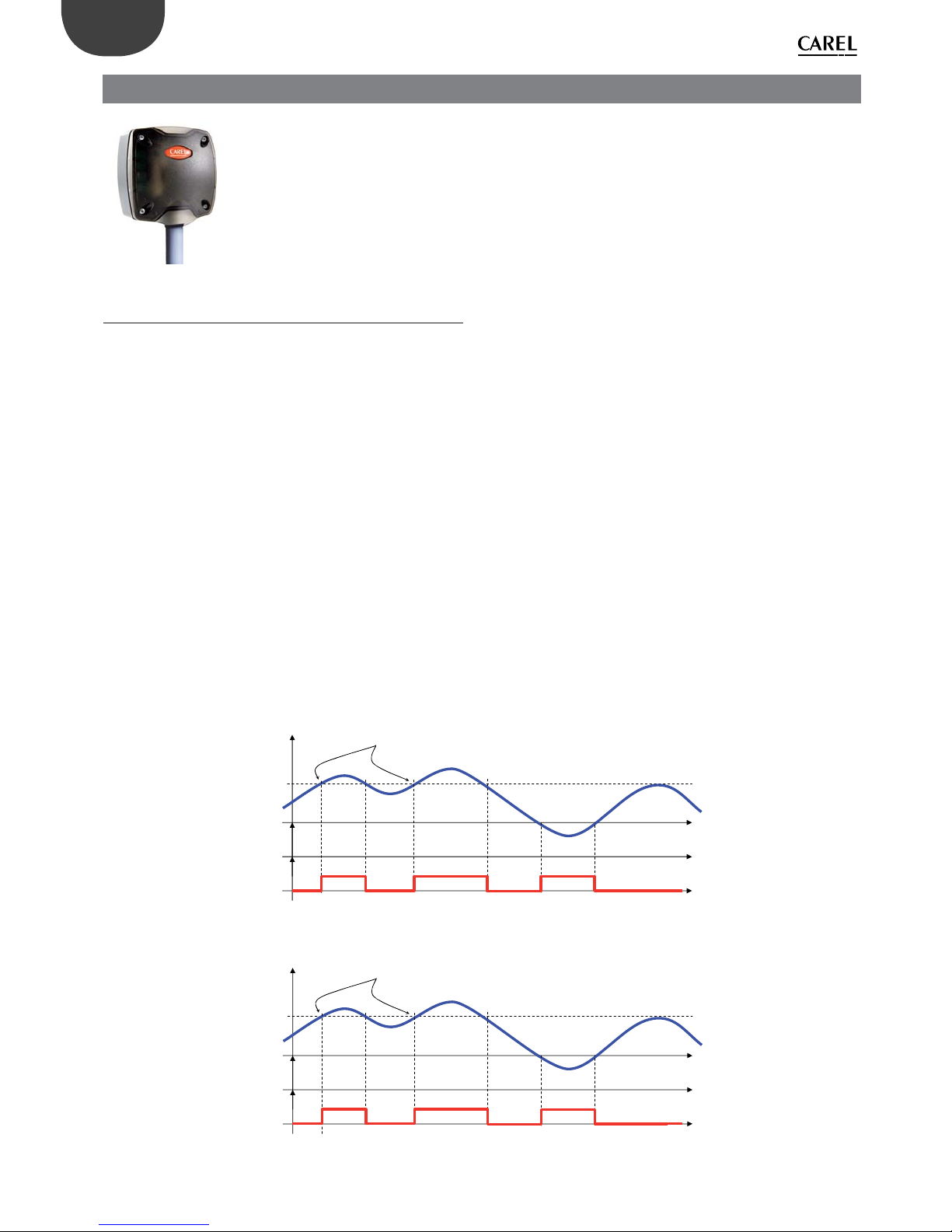
26
ENG
“Wireless probes” +0300030EN - rel. 1.0 - 16.07.2010
6. SI INDUSTRIAL SENSOR
The SI Sensor is used to measure the temperature, humidity and light intensity in residential or light industrial applications. It features one
temperature probe, one humidity probe and one light intensity sensor to measure ambient conditions, and sends the data measured
to the Access Point at regular intervals..
Fig. 6.a
6.1 Functions implemented and supervisor
variables available
Parameters and functions
• Temperature measurement performed every transmission cycle;
• Humidity measurement performed every transmission cycle;
• Light intensity measurement performed every transmission cycle;
• Temperature alarm when exceeding the minimum and maximum
thresholds set by parameter;
• Humidity alarm when exceeding the minimum and maximum thresholds
set by parameter;
• Light intensity alarm when exceeding the minimum and maximum
thresholds set by parameter;
• Low battery level alarm;
• Data transmission at settable interval in minutes (this a ects battery life);
Main variables available to the supervisory system
• Temperature;
• Humidity;
• Light intensity;
• Battery level in mV ;
• Wireless signal level in dBm +100 (8 = low signal, 15 to 30 = medium signal,
greater than 30 excellent).
• Temperature, humidity and light alarm status relative to high and low
thresholds.
• Data transmission interval;
• TimeStamp for recording the instant measurement, expressed in hh:mm.
Temperature alarm function:
Temp °C
Time
Alarm ON Alarm ON Alarm ON
HI_TEMP_TRESHOLD
High temperature event started normal condition
LO_TEMP_TRESHOLD
EN_HI_TEMP_ALM
ALARM
Fig. 6.b
Humidity alarm function:
Humidity
rH%
Time
Alarm ON Alarm ON Alarm ON
HI_UMID_TRESHOLD
High humidity event started normal condition
LO_UMID_TRESHOLD
EN_HI_TEMP_ALM
ALARM
Fig. 6.c

27
ENG
“Wireless probes” +0300030EN - rel. 1.0 - 16.07.2010
Light intensity alarm function:
Luminous
100%
Time
Alarm ON
Alarm ON
Alarm ON
HI_LUX_TRESHOLD
High luminous event started normal condition
LO_LUX_TRESHOLD
EN_HI_TEMP_ALM
ALARM
Fig. 6.d
The sensor compares the temperature, humidity and light intensity measured
against the parameters that de ne the alarm limits.
There are no delays in activating the alarm signal; as soon as the acquired
value is higher than the maximum limit or lower than the minimum limit the
corresponding ag is activated.
If Temperature > High temperature limit --> high temp. alarm =1
If Temperature ≤ High temperature limit --> high temp. alarm =0
If Temperature < Low temperature limit --> low temp. alarm =1
If Temperature ≥ Low temperature limit --> low temp. alarm =0
If Humidity > Maximum humidity limit --> maximum humidity alarm =1
If Humidity ≤ Maximum humidity limit --> maximum humidity alarm =0
If Humidity < Minimum humidity limit --> minimum humidity alarm =1
If Humidity ≥ Minimum humidity limit --> minimum humidity alarm =0
If Light > Maximum light limit --> maximum light alarm =1
If Light ≤ Maximum light limit --> maximum light alarm =0
If Light < Minimum light limit --> minimum light alarm =1
If Light ≥ Minimum light limit --> minimum light alarm =0
6.2 Technical speci cations
Power supply 3.6V 2500 mAh lithium battery, “AA” size
Maximum power input 100 mW
Battery life in normal operating
conditions
From 3 to 8 years, depending on the transmission time set. (CAREL is not responsible for the
speci ed battery life)
Radio frequency speci cations Frequency: selectable from 2405 to 2480 MHz
Power transmitted: 0dBm
Wireless protocol: ZigBee
Operating conditions
-20T70 °C
10 to 90 rH%
0 to 100 (Light intensity)
Storage conditions -20T70 °C - humidity range: <80% RH non-
cond.
Precision of temperature measurement and humidity
Temperature ±1°C 0T50 °C
Humidity ±5 rH%
Light intensity ±20% (depends on the spec-
trum)
Index of protection against atmospheric agents
IP55
Classi cation according to protection against electric shock
Can be integrated into class I or class II
appliances
Environmental pollution Normal
PTI of insulating materials 250 V
Period of stress across the insulating parts
Long
Category of resistance to heat
and re
category D (box and cover)
Immunity against voltage surges category 1
Software class and structure Class A
Disposal observe local legislation for the disposal of
electrical material
Product code WS01F01M00 - Wireless industrial temperatu-
re, humidity and light intensity sensor ver. SI
battery powered
Accessories WS00BAT000 - Battery, single package
0000000722 Magnet for activating SW1
Tab. 6.a

28
ENG
“Wireless probes” +0300030EN - rel. 1.0 - 16.07.2010
6.3 List of parameters and variables, SI Sensor
Below is the table of supervisor parameters for the SI Sensors.
Variable Index Name Description Def. Min Max UoM “Type R/W”
HR0 CMD_PASSW_1 ‘Command Password (1) ‘ 0 0 65535 - R/W
HR1 TRANSM_CYCLE ‘TX data cycle time’ 60 5 3600 sec R/W
HR2 LO_TEMP_TRESHOLD ‘Threshold low Temp.’ -500 -500 1000 0,1°C R/W
HR3 HI_TEMP_TRESHOLD ‘ Threshold high Temp.’ 1000 -500 1000 0,1°C R/W
HR4 LO_LIGHT_TRESHOLD ‘Threshold low Light’ 0 0 10000 - R/W
HR5 HI_LIGHT_TRESHOLD ‘Threshold high Light’ 100 0 10000 - R/W
HR6 LO_UMID_TRESHOLD ‘Threshold low Umidity’ 0 0 100 %Ur R/W
HR7 HI_UMID_TRESHOLD ‘Threshold high Umidity’ 100 0 100 %Ur R/W
HR8 COEFF_LIGHT ‘Light multiplicative coe cient’ 1000 0 30000 - R/W
HR9 OFFS_TEMP ‘O set Temperature Measure’ 0 -100 100 0,1°C R/W
HR10 UNIT_MIS ‘Temperature unit of measure (0= Celsius; 1=Fahrenheit)’ 0 0 1 - R/W
HR11 MIN_RSSI_LEVEL ‘Minimum rssi level counted (internal use)’ 0 0 99 - R/W
HR12 CNT_REJOIN ‘Max counter value before rejoin (internal use)’ 30 1 255 - R/W
IR0 MACHINE_CODE ‘Unit type - machine code’ 65 - - - R
IR1 FW_VERSION ‘Firmware version (Major/Minor)’ 2051 - - - R
IR2 TX_MESSAGE_CNT ‘Total Number of TX radio messages’ 0 0 65535 - R
IR3 RX_MSG_LEVEL ‘Radio signal Level’ - 0 100 dBm+100 R
IR4 BATTERY_LEVEL ‘Battery Level’ - 0 3600 mV R
IR5 LIGHT_EFFIC ‘RMS light’ - 0 65535 - R
IR6 TEMPERATURE ‘ Temperature Value’ - -500 1000 0,1°C R
IR7 LIGHT ‘Light ’ - 0 65535 - R
IR8 UMIDITY ‘Umidity Value’ - 0 100 %Ur R
IR9 MAC_ADDR_0 ‘Unit unique identi er Mac-Address LSB’ - 0 65535 - R
IR10 MAC_ADDR_1 ‘Unit unique identi er Mac-Address MSB’ - 0 65535 - R
IR11 ID_SER_ADDR ‘Carel_ID, Serial_Address, DIP-SW value’ - 16 127 - R
IR12 LAST_RX_DELAY ‘Time from last Access Point Rx message’ - 0 65535 - R
IR13 RX_MESSAGE_CNT ‘Counter - AP Rx messages’ - 0 65535 - R
IR14 TIME_STAMP ‘Time stamp for Temp. readings (100*hour+minute)’ - 0 2359 hh*100+mm R
IR15 AP_RX_RADIO_LEV ‘Livello Radio messaggi Rx da AccessPoint’ - 0 100 dBm+100 R
IR16 NETWORK_ID ‘Network address’ - 0 65535 - R
IR17 ‘MIRROR_IS’ ‘Mirror Input Status (internal use)’ - 0 65535 - R
CS0 EN_CMD_PW ‘Trig. PWD (internal use)’ 0 0 1 - R/W
IS0 HI_TEMP_ALARM ‘High Temperature Alarm’ - 0 1 - R
IS1 LO_TEMP_ALARM ‘Low Temperature Alarm’ - 0 1 - R
IS2 HI_LIGHT_ALARM ‘High Light Alarm’ - 0 1 - R
IS3 LO_LIGHT_ALARM ‘Low Light Alarm’ - 0 1 - R
IS4 HI_UMID_ALARM ‘High Umidity Alarm’ - 0 1 - R
IS5 LO_UMID_ALARM ‘Low Umidity Alarm’ - 0 1 - R
IS6 PROBE_ERROR ‘Probe Failure Alarm’ - 0 1 - R
IS7 LOW_BATT ‘Battery Alarm’ - 0 1 - R
Tab. 6.b
Key:
HR = Holding register
IR = Input register
CS = Coil Status
IS = Input Status
6.4 SI Sensor installation notes
1. Remove the cover by unscrewing the four screws at the front.
2. Fasten the case to the wall with minimum two screws, remembering that this is a radio device and therefore the necessary details must be observed.
3. Connect the two NTC temperature probes (10K@25°C Beta(25/85) = 3435K) to the terminals provided.
4. Connect the two digital inputs to the terminals provided (door and defrost).
5. Select the network address on the dipswitches.
6. Remove the insulating protection on the battery.
7. Perform the binding procedure.
8. Check the quality of the wireless signal; stimulate the sensor by pressing button T1 or activating magnetic switch SW1 and check the ashes on LED L3.
- 1 ash, wireless connection with minimum signal strength;
- 2 ashes, wireless connection with medium signal strength;
- 3 ashes, wireless connection with excellent signal strength;
9. Close the sensor again.
10. Make sure that the transmitter is in an optimum position with reference to the receiver, once installation is complete, checking the transmitted signal level in
the corresponding supervisor variable.
Fig. 6.e

29
ENG
“Wireless probes” +0300030EN - rel. 1.0 - 16.07.2010
6.5 Physical dimensions
72
72
44
170
45
mounting holes
98
105
PG9
CH19
Fig. 6.f
6.6 Application example
Fig. 6.g
Fig. 6.h
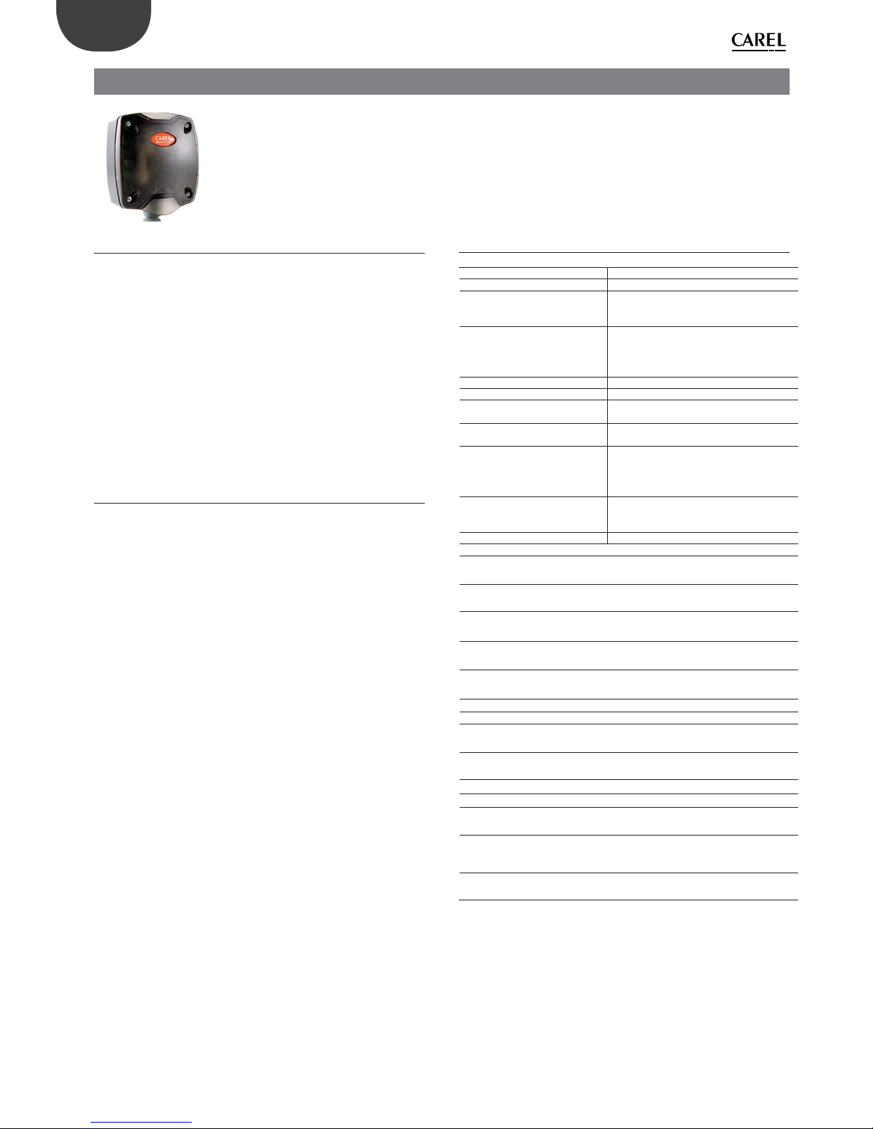
30
ENG
“Wireless probes” +0300030EN - rel. 1.0 - 16.07.2010
7.3 Technical speci cations
Power supply 3.6V 2500 mAh lithium battery, “AA” size
Maximum power input 100 mW
Battery life in normal operating
conditions
From 3 to 8 years, depending on the transmission time set (CAREL is not responsible for the
speci ed battery life)
Radio frequency speci cations
Frequency: selectable from 2405 to 2480
MHz
Power transmitted: 0dBm
Wireless protocol: ZigBee
Operating conditions 0T50°C, <80% RH non-condensing
Storage conditions -20T70°C, <80% RH non-condensing
Range of temperature reading for
NTC probes 1 and 2
-50T90°C, <80% RH non-condensing
Precision of temperature measurement
± 1 °C -10T30°C; ± 2 °C -30T40°C
Temperature measurement inputs
Measurement from -50 a + 90 C. Resolution
0.1 C. Compatible
Power transmitted: 0dBm
Wireless protocol: ZigBee
Digital inputs For voltage-free contacts (isolated) - Closing cur-
rent 0.01 mA. Use self-cleaning contacts, Open
collector transistor or Reed Switch
MIN pulse duration 10 ms
MAX pulse frequency 20 Hz
Digital input current 700 µA
Connections - screw terminalsfor
probes and digital inputs
Plug-in terminal step 3.81
cable size 0.5 mm2 (max 1.5 mm2)
Maximum connection length Cable max length 10 m for probes and digital
inputs
Index of protection against atmospheric agents
IP55 (see note 1)
Classi cation according to protection against electric shock
Can be integrated into class I or class II
appliances
Environmental pollution Normal
PTI of insulating materials 250 V
Period of stress across the insulating
parts
Long
Category of resistance to heat and
r e
category D (box and cover)
Immunity against voltage surges category 1
Software class and structure Class A
Disposal observe local legislation for the disposal of
electrical material
Product code WS01E02M00 – Wireless pulse counter ver. CI
battery powered 2NTC- 2DI -50 to 90°C
Accessories WS00BAT000 - Battery, single package
0000000722 Magnet for activating SW1
Tab. 7.a
Note:
the index of protection is maintained only if a single cable is used for power and
RS485 communication with an outside cross-section of less than 8 mm.
7. CI PULSE COUNTER
IThe pulse counter is a device used together with suitable energy meter modules to monitor power, gas and water consumption.
It can manage two energy meters on the two digital inputs, and is tted for connection of two external passive NTC temperature
probes 10K@25°C (Beta(25/85) = 3435K). Closing the contacts on the digital inputs increases the value of two separate pulse
counters.
Fig. 7.a
7.1 Functions implemented
Count pulses on ID1 (counter 1);
Count pulses on ID2 (counter 2);
Data transmission at settable interval in minutes (this a ects battery life);
Main variables available to the supervisory system
• Impulse counter 1 value
• Impulse counter 2 value
• NTC temperature probe 1 in °C
• NTC temperature probe 2 in °C
• NTC 1 - NTC 2 temperature di erence.
• Battery level in mV ;
• Wireless signal level in dBm +100 (8 = low signal, 15 to 30 = medium signal,
greater than 30 excellent).
• Data transmission interval;
• TimeStamp for recording the instant measurement, expressed in hh:mm.
7.2 Parameters and functions
The device continuously and separately counts the pulses received on the two
digital inputs, IN_1 and IN_2. The counter value is transmitted by the device at
a frequency that depends on the transmission time parameter, according to
the application and expected battery life. The counter value is saved in nonvolatile memory every six hours of continuous device operation.
Press the button on the sensor to send the sensor data manually, or check the
connection.
Data transmission activation:
Wireless transmission is activated in the following conditions:
• Brie y pressing the button;
In all other cases, data transmission is de ned by the set transmission time.
Enable and disabling the analogue inputs
EN_NTC_1 and EN_NTC_2 enable and disable the probe inputs. The probe
inputs can be enabled and disabled using parameters EN_NTC_1 and EN_
NTC_2 respectively. If a probe input is disabled, the temperature reading is
equal to 0°C; in this event, the probe alarm fault is not managed and remains
constantly inactive (0).
By default the probe inputs are enabled.

31
ENG
“Wireless probes” +0300030EN - rel. 1.0 - 16.07.2010
7.4 List of parameters and variables, CI Pulse Counter
Below is the table of supervisor parameters for the CI devices; this also applies to the RC Router-Pulse Counter (only for the special pulse counter function).
Variable Index Name Description Def. Min Max UoM “ Type R/W”
HR0 CMD_PASSW_1 ‘Command Password (1)’ 0 0 65535 - R/W
HR1 TRANSM_CYCLE ‘TX data cycle time’ 60 5 3600 sec R/W
HR2 CMD_PASSW_2 ‘Command Password (2)’ 0 0 65535 - R/W
HR3 CMD_PASSW_3 ‘Command Password (3)’ 0 0 65535 - R/W
HR4 INC_COUNTER ‘Incrase counter for input’ 1 1 100 - R/W
HR5 MIN_RSSI_LEVEL ‘Minimum rssi level counted (internal use)’ 0 0 99 - R/W
HR6 CNT_REJOIN ‘Max counter value before rejoin (internal use)’ 30 1 255 - R/W
IR0 MACHINE_CODE ‘Unit type - machine code’ (67=ZED, 68=ZR) 67/68 - - - R
IR1 FW_VERSION ‘Firmware version (Major/Minor)’ 2051 - - - R
IR2 TX_MESSAGE_CNT ‘Total Number of TX radio messages’ 0 0 65535 - R
IR3 RX_MSG_LEVEL ‘Radio signal Level’ 0 0 100 dBm+100 R
IR4 BATTERY_LEVEL ‘Battery Level’ - 0 3600 mV R
IR5 PROBE_TMP_DIFF ‘ Temperature di erence NTC1 probe - NTC2 probe’ - -500 1000 0,1°C R
IR6 TEMPERATURE_1 ‘Temperature Value probe 1’ - -500 1000 0,1°C R
IR7 TEMPERATURE_2 ‘Temperature Value probe 2’ - -500 1000 0,1°C R
IR8 IN_1_COUNTER_LOW ‘Input Counter IN_1 (Low)’ 0 0 65535 - R
IR9 IN_1_COUNTER_HIG ‘Input Counter IN_1 (High)’ 0 0 65535 - R
IR10 IN_2_COUNTER_LOW ‘Input Counter IN_2 (Low)’ 0 0 65535 - R
IR11 IN_2_COUNTER_HIG ‘Input Counter IN_2 (High)’ 0 0 65535 - R
IR12 IN_1_LAST_COUNT ‘Input Counter IN_1 in last sampling period’ 0 0 65535 - R
IR13 IN_1_LAST_TIME ‘Sampling period IN_1’ 0 0 65535 sec R
IR14 IN_2_LAST_COUNT ‘Input Counter IN_2 in last sampling period’ 0 0 65535 - R
IR15 IN_2_LAST_TIME ‘Sampling period IN_2’ 0 0 65535 sec R
IR16 MAC_ADDR_0 ‘Unit unique identi er Mac-Address LSB’ - 0 65535 - R
IR17 MAC_ADDR_1 ‘Unit unique identi er Mac-Address MSB’ - 0 65535 - R
IR18 ID_SER_ADDR ‘Carel_ID, Serial_Address, DIP-SW value’ - 16 127 - R
IR19 LAST_RX_DELAY ‘Time from last AP Rx message’ - 0 65535 - R
IR20 RX_MESSAGE_CNT ‘Counter - AP Rx messages’ - 0 65535 - R
IR21 TIME_STAMP ‘Time stamp for Temp. readings (100*hour+minute)’ - 0 2359 hh*100+mm R
IR22 AP_RX_RADIO_LEV ‘Radio Lev. for AP Rx messages’ - 0 100 dBm+100 R
IR23 NETWORK_ID ‘Network address’ - 0 65535 - R
IR24 ‘MIRROR_IS’ ‘Mirror Input Status (internal use)’ - 0 65535 - R
CS0 EN_CMD_PW ‘Trig. PWD (internal use)’ 0 0 1 - R/W
CS1 EN_NTC_1 ‘Enable Probe NTC_1’ 1 0 1 - R/W
CS2 EN_NTC_2 ‘Enable Probe NTC_2’ 1 0 1 - R/W
IS0 IN_1_STATUS ‘Digital Input State IN_1’ - 0 1 - R
IS1 IN_2_STATUS ‘Digital Input State IN_2’ - 0 1 - R
IS2 PROBE_ERROR_1 ‘Probe 1 Failure Alarm’ - 0 1 - R
IS3 PROBE_ERROR_2 ‘Probe 2 Failure Alarm’ - 0 1 - R
IS4 ALM_GENERAL ‘General Unit Alarm’ - 0 1 - R
IS5 LOW_BATT ‘Battery Alarm’ - 0 1 - R
Tab. 7.b
Key:
HR = Holding register
IR = Input register
CS = Coil Status
IS = Input Status

32
ENG
“Wireless probes” +0300030EN - rel. 1.0 - 16.07.2010
7.5 CI Pulse Counter installation notes
1. Remove the cover by unscrewing the four screws at the front.
2. Fasten the case to the wall with minimum two screws, remembering that
this is a radio device and therefore the necessary details must be observed.
3. Connect the two NTC temperature probes (10K@25°C Beta(25/85) =
3435K) to the terminals provided.
4. Connect the two digital inputs to the terminals provided (door and
defrost).
5. Select the network address on the dipswitches.
6. Remove the insulating protection on the battery.
7. Perform the binding procedure.
8. Check the quality of the wireless signal; stimulate the sensor by pressing
button T1 or activating magnetic switch SW1 and check the ashes on
LED L3:
- 1 ash, wireless connection with minimum signal strength;
- 2 ashes, wireless connection with medium signal strength;
- 3 ashes, wireless connection with excellent signal strength;
9. Close the sensor again.
10. Make sure that the transmitter is in an optimum position with reference
to the receiver, once installation is complete, checking the transmitted
signal level in the corresponding supervisor variable.
Fig. 7.b
7.6 CI Pulse Counter physical dimensions
94
102
40
108
50
70
fori di fissaggio / mounting holey
Fig. 7.c
7.7 CI Pulse Counter electrical connections
IN_1
NTC1
NTC2
IN_2
Fig. 7.d
1. Probe input NTC_1 10K@25°C Beta(25/85) = 3435K (e.g. NTC*HP* or
NTC*WP*);
2. Probe input NTC_2 10K@25°C Beta(25/85) = 3435K (e.g. NTC*HP* or
NTC*WP*);
3. Pulse counter digital input IN_1;
4. Pulse counter digital input IN_2;
The maximum cable length for NTC probes and digital inputs is 10 m
7.8 Connection example
Fig. 7.e
SW1
T1

33
ENG
“Wireless probes” +0300030EN - rel. 1.0 - 16.07.2010
8.1 Main functions
• Manual opening/closing of the wireless domain (button). Via software or
rTM SE handheld for binding the devices (sensors or Routers);
• Automatic selection of the channel wireless to be used.
• Count the number of sensors connected;
8.2 Parameters and functions
The Access Point manages the wireless network and the wireless connection
of all the units, making these accessible to the supervisory system via the
Modbus RS485 serial connection.
For all the sensors managed directly, it stores a copy of all the parameters and
variables, which are updated every time data is transmitted via the wireless
connection.
The Access Point makes the data for all the peripherals available to the
supervisor at all times, even if wireless transmission is performed at set
intervals.
Setting the operating mode
Parameter HR_03 used to set the Access Point operating mode.
The table below summarises the various operating modes:
Value Description Notes
HR_03 = 21 Communication with
Router-Bridge disabled
(default)
HR_03 = 17 Communication with
Router-Bridge enabled
Filters should be con gured to set the
min and max addresses of the devices
connected via Router-Bridge (HR_11 and
HR_12);
8.3 Con guration
The following chapter describes the procedure for setting the address,
con guration and connection of the devices, so as to create a wireless domain
that is connectable to a controller via the Modbus RTU protocol.
A fundamental step is commissioning, which involves the unique identi cation
of each device by:
• Assigning a unique network address to each device;
• Binding of the devices to a domain so that the devices can communicate
with each other. All the other devices cannot communicate even if they are
reached by the wireless signal.
Security of communication over the network is guaranteed by the 128 bit
encryption key (AES) written inside the program on each device.
In normal operation, only the serial address is used, which is also unique within
the network and is su cient to identify each unit.
WARNING!
Two units cannot have the same serial address. Therefore pay careful attention
when assigning the network addresses to the sensors and Access Points so
that there are no devices with the same serial address, also considering any
instruments connected to the remote wired network via the Bridge. This
would create con icts and interference in the storing of temperature data.
8.4 Setting the address
This is a fundamental phase in setting up the system, and allows each device
to be identi ed uniquely by assigning a unique network address to each
device (Modbus® network address).
Access Point
• Assign the CAREL network address and baud rate using 4 dipswitches as
shown in the following table;
• Power up the Access Point;
• Check that the LED 1 is always on and the others are o . If the LEDs are not
in this status, reset the Access Point (see Resetting the devices).
DIP: 1 2 3 4
++
G
--
Rx- Rx+ GND
L1
L2 L3
T1
DIP 1-2-3 network address selection
DIP 4 baud of network selection
Fig. 8.b
Important: the address can be changed after switching o /on.
Dipswitch
Access Point address
Serial port baud rate
(Bit/S) N82
1234
OFF OFF OFF OFF 0
(settable from the super-
visor)
9600
ON OFF OFF OFF 1 9600
OFF ON OFF OFF 2 9600
ON ON OFF OFF 3 9600
OFF OFF ON OFF 4 9600
ON OFF ON OFF 5 9600
OFF ON ON OFF 6 9600
ON ON ON OFF 7 9600
OFF OFF OFF ON 0
(settable from the super-
visor)
19200
ON OFF OFF ON 1 19200
OFF ON OFF ON 2 19200
ON ON OFF ON 3 19200
OFF OFF ON ON 4 19200
ON OFF ON ON 5 19200
OFF ON ON ON 6 19200
ON ON ON ON 7 19200
Tab. 8.a
Creating the network and selecting the wireless
communication channel
The wireless system requires of use a transmission channel for the
communication of the wireless messages between the various devices.
The best communication channel for the environment in question is
automatically selected by the Access Point, using the following procedure:
Power up the Access Point (LED 1 must be on steady);
1 2 3
Press the button and check the activation sequence:
1 2 3
8. AP ACCESS POINT
This is the coordinator of a wireless network as well as the gateway for the information between the ZigBee™ protocol and the CAREL
supervisor side (pCO, PlantVisor, PlantWatch or any CAREL master device). Up to 7 Access Points can be connected to the same serial line.
Fig. 8.a

34
ENG
“Wireless probes” +0300030EN - rel. 1.0 - 16.07.2010
For 10s: LED 1 and 2 on
1 2 3
For 30s: LED 2 on (search for ZigBee channel)
1 2 3
LED 1 ashes slowly (1s).
The Access Point is ready for use, the wireless network has been initialised.
The transmission channel has been selected and will be sent to the Routers
and sensors during the binding phase.
Important:
• If the sequence does not occur as indicated, reset the device (see Resetting
the device);
• If the Access Point is reset, all the instruments bound to it will be
disconnected and will need to be bound again.
8.5 Binding procedure
The logical connection between the Access Point and the wireless devices is
called binding. This operation must be performed after setting the addresses
and selecting the communication channel.
Power up the Access Point and check that LED 1 ashes slowly (1s).
1 2 3
(In the drawing LED 1 is shown ashing slowly).
OPEN DOMAIN: press button T1. LED 1 ashes quickly (around 0.25s)
1 2 3
(In the drawing LED 1 is ashing quickly).
In this phase, new devices can be bound.
CLOSE DOMAIN: After having connected all the devices, press the button to
close the domain (LED 1 starts ashing slowly again, around 1s).
1 2 3
(In the drawing LED 1 is ashing slowly).
NOTE: The domain closes automatically 15 minutes after last opening.
The domain can be opened/closed on the Access Point from the Modbus
controller, using the following procedure, checking the status using
parameters IS_00, IS_01:
Modbus® variables indices
• OPEN DOMAIN: Select
Enable command
HR_00=5266
CS_00 = 1
• CLOSE DOMAIN: Select
Enable command
HR_00=5267
CS_00 = 1
• Network domain status: Network open,
Binding active
Network closed
IS_01 = 1
IS_01 = 0
• Access Point with
Network Active:
Network initialised
Network NOT
initialised
IS_00 = 1
IS_00 = 0
Tab. 8.b
The wireless network can also be opened or closed from the rTM SE handheld.
For further information, see the speci c chapter further on.
8.6 Resetting the device
To reset the device, proceed as follows:
Press and hold button T1 (L1 ashes quickly)
1 2 3
after 10s L3 comes on for 4 to 5s
1 2 3
Release button T1 when LED L1 remains on steady.
1 2 3
Wait until the 3 LEDs ash together 3 times and then switch o .
1 2 3
Flash quickly
When L1 remains on steady the device has been reset.
1 2 3
Note: all devices previously bound will be removed from the Access Point/
Router (no. devices connected=0).
8.7 Serial communication parameters
The Access Point data and the data of all the devices making up the network can
be accessed via ModBus-RTU serial communication protocol.
The serial communication parameters are as follows:
Speed: 9600 Bps (DIP4=o ) / 19200Bps (DIP4=on)
Data bits: 8
Parit y: None
Stop bits: 2
Flow control: None
Given the nature of the Modbus protocol, the data for all the devices, including
the Gateway, are divided into four memory areas:
IRxx InputRegister (16 bit read-only variables)
ISxx InputStatus (1 bit read-only variables)
HRxx HoldingRegister (16 bit variables, generally non-volatile)
CSxx CoilStatus (1 bit variables)
The codes of the functions implemented in the Access Point are as follows:
01 - READ COIL STATUS
02 - READ INPUT STATUS
03 - READ HOLDING REGISTER
04 - READ INPUT REGISTER
05 - FORCE SINGLE COIL
06 - PRESET SINGLE

35
ENG
“Wireless probes” +0300030EN - rel. 1.0 - 16.07.2010
8.8 Table of LED status
Action LED sequence (with times
in sec.)
Meaning of the signal
--- L1 ON Access Point ON with
wireless channel not
con gured
Press button T1 ( rst
time)
L1 and L2 ON (10s)
L2 ON (30s)
L1 ashing slowly (1s)
Select wireless channel
PANID and extended
PANID automatically
--- L1 ashing slowly (1s) Access Point ON with
wireless channel con gured
--- L3 Normally o . On when
sending or receiving a
wireless message
Press button T1 to
open wireless network
L1 ashing quickly (0.25s) Access Point with the
wireless network open
(ready for binding the
devices)
Press and hold button T1L1, ashing quickly
L3 on for 2s
L1 on steady
Release button T1
L1, L2, L3 ash quickly and at
the same time several times
L1 on steady (end of the
procedure)
Reset without disconnecting power
--- L2
Router with a good connection in the vicinity
O No Router with
good connection in the
vicinity
ash Router with
good connection in the
vicinity
ashes two Routers
with good connection
in the vicinity
ashes four or
more Routers with
good connection in the
vicinity
Tab. 8.c
The table describing the LEDs does not refer to normal operation of the
Access Point, but rather the procedure for de ning the network, an operation
performed only during con guration. The last row only describes the
behaviour of the LED (L2 only) during the “normal” operation of the device.
8.9 Technical speci cations
Power supply 12-24 Vac/dc ±10% 100mA; 50/60 Hz;
Use a class II safety transformer with
minimum power rating of 2 VA. 12 Vac
transformer recommended
Maximum power input 1 VA
Radio frequency speci cations Frequency: selectable from 2405 to
2480 MHz (by parameter or auto-
matically, see the table of supervisor
parameters)
Power transmitted: 0dBm
Wireless protocol: ZigBee
RS485 transmission speed 9600/19200 b/s
Max. num. of sensors that can be bound 30 sensors (60 by adding a Router)
16 Routers
Operating conditions 0T50°C, <80% RH non-condensing
Storage conditions -20T70°C, <80% RH non-condensing
Connections - screw terminals for
power supply
-Power supply terminal: plug-in cables
max size 1.5 mm
- RS485 communication terminal:
plug-in cables max size 1.5 mm (use
shielded cable with shield connected
to GND)
- RS485 communication terminal:
plug-in cables max size 1.5 mm (use
shielded cable with shield connected
to GND)
Type of cable Shielded cable max length 1000 m
(RS485), 100 m (Power supply)
Assembly wall-mounted by screws
Display/Con guration Read and write parameters via RS485
Protocol RS485 Modbus RTU
Index of protection IP55 (see note)
Classi cation according to protection
against electric shock
Can be integrated into class I or class II
appliances
Environmental pollution Normal
PTI of insulating materials 250 V
Period of stress across the insulating
parts
Long
Category of resistance to heat and re category D (box and cover)
Immunity against voltage surges category 2
Software class and structure Class A
Disposal observe local legislation for the disposal
of electrical material
Product code WS01AB2M20 - Access Point 12-24
Vac/dc,
Accessories TRASP3E120 – Plug-in transformer 3VA
230-12Vac
TRADR4W012 Panel transformer 3VA
230-12Vac
Tab. 8.d
Note:
1. The index of protection is maintained only if a single cable is used for
power and RS485 communication with an outside cross-section of less
than 8 mm.
2. It’s recommended to use an external junction box for creating the
connections and tting the transformer.

36
ENG
“Wireless probes” +0300030EN - rel. 1.0 - 16.07.2010
8.10 List of Access Point system variables
(alphabetical order)
Tab. 8.e
Note:
the parameters described are divided into 4 groups based on the Modbus
standard:
HR_xx Read/write registers (16-bit word)
IR_xx Read-only registers (16-bit word)
CS_xx Read/write bits (1-bit)
IS_xx Read-only bit (1-bit))
Parameters speci ed as: “Con guration” or “Verify NETWORK” are not normally
used in the supervisor application. They can on the other hand be used by
con guration systems (commissioning tool).
AP_ALTER_ADDR Alternative address of the Access Point (used if
dipswitch=0) default=1. Used to set an alternative
address to the on set by dipswitch (make sure to
avoid network con icts); The new address must be
set for parameter AP_ALTER_ADDR (HR_10);
AP_CONN Indicates whether the Access Point is managing the
wireless network (1 = yes);
AP_OPEN Indicates that the network is open and new devices
can be bound (1 = yes);
AP_RESET_CNT Wireless network veri cation parameters for internal
use;
AP_RESET_TYPE Wireless network veri cation parameters for internal
use;
AP_TX_RADIO_LEV Indicates the wireless transmission and reception le-
vels for the Access Point in dBm +100. For minimum
reception, the value must be greater than 8, medium
quality reception from 15 to 30, and good quality
values greater than 30;
CMD_PASSW_1….7 Commands used to con gure the wireless network.
Used by installation and con guration tools;
CONN_AP Number of units directly connected to the Access
Point;
CONN_BINDED Total number of units visible in the network from the
remote wired network Bridge (see Bridge);
CONNECTED_UNIT Total number of sensors connected to the wireless
network and managed by Access Point;
EN_CMD_PW Commands used to con gure the wireless network.
Used by installation and con guration tools;
FREE_BUFFER Wireless network veri cation parameters for internal
use;
FW_VERSION Access Point FW revision
ID_SER_ADDR Serial address value, set by dipswitch. Can be used as
the unit identi er;
MAC_ADDR_0 Unique 32 bit unit identi er (0 = LSB), used to uni-
quely identify each unit;
MAC_ADDR_1 Unique 32 bit unit identi er (1 = MSB), used to
uniquely identify each unit;
MACHINE_CODE Peripheral identi er for the supervisor (112 for the
Access Point);
MAX_SELEC_ADDR
Maximum address value allowed for devices
behind the Router-Bridge, default=247
MIN_SELEC_ADDR Minimum address value allowed for devices behind
the Router-Bridge, default=1
NET_CHANNEL ZigBee Network transmission channel. Uniquely
de nes the wireless network used by the system for
communication (Access Point, Repeaters, Sensors).
The value is set during the con guration procedure
or using the commissioning tool;
NET_PANID ZigBee network transmission identi er. Uniquely
de nes the wireless network used by the system for
communication (Access Point, Repeaters, Sensors).
The value is set during the con guration procedure
or using the commissioning tool;
NET_PANID_EXT_0…..3 Network Extended PanID
Network identi ers. Guarantee greater security on
the wireless network. Fundamental parameters for
cloning the ZigBee network
OFFLINE_MODE Access Point response mode for units that are O ine.
Parameter HR_03 (Operating mode, default value 21;
HR_03 = 21 Communication with Router-Bridge
disabled (default);
HR_03 = 17 Communication with Router-Bridge
enabled. Filters should be con gured to set the min
and max addresses of the devices connected via
Router-Bridge (HR_11 and HR_12);
Note: a peripheral is considered O ine by the Access
Point after 4 query cycles, i.e. after a time of 4 x
TRANSM_CYCLE..
RES_COUNTER Wireless network veri cation parameters for internal
use;
ROUTER_CONN_NEARBY Number of Routers in the vicinity;
ROUTER_CONNECTED Total number of routers connected to the network;
ROUTER_GOOD_SIGNAL Number of Routers in the vicinity with a good wire-
less signal, ≥ 30 dB;
ROUTER_TX_TIME Transmission time for wireless refresh signal (aggre-
gation)
RX_MSG_LEVEL Indicates the wireless transmission and reception le-
vels for the Access Point in dBm +100. For minimum
reception, the value must be greater than 8, medium
quality reception from 15 to 30, and good quality
values greater than 30;
RX_MSG_LEVEL Wireless network veri cation parameters for internal
use;
TIME_STAMP Clock in hours:minutes for recording the times the
sensors measure and send data. This is updated/
incremented every minute by the Access Point, the
value can be set from the supervisor to align it with
a real clock. Invalid values are rounded o to the nearest (hour: minutes). The value is lost in the event of
power failures, restarting from 00:00. If synchronisation is required, the supervisor must reset the value;

37
ENG
“Wireless probes” +0300030EN - rel. 1.0 - 16.07.2010
8.11 List of parameters and variables, Access
Point versione Modbus RTU
In order to access the information from the system of sensors, the supervisor
connection settings are as follows:
Modbus® RTU protocol;
baud rate 9600 8, N, 2 or 19200 8, N, 2. Below is the table of supervisor variables
for the system components.
Variable Index Name Description Def. Min Max UoM “Type R/W”
HR0 ‘CMD_PASSW_1’ ‘Command Password (1)’ 0 0 65535 - R/W
HR1 ‘CMD_PASSW_2’ ‘Command Password (2)’ 0 0 65535 - R/W
HR2 ‘CMD_PASSW_3’ ‘Command Password (3)’ 0 0 65535 - R/W
HR3 ‘OFFLINE_MODE’ ‘Mode Status Access-Point’ 21 1 63 - R/W
HR4 ‘TIME_STAMP’ ‘Clock Counter as hh:mm for RX-data TimeStamp’ 0 0 2359 hh*100+mm R/W
HR5 ‘ROUTER_TX_TIME’ ‘Sending time to nd new ways (default 20sec)’ 20 10 60 sec R/W
HR6 ‘CMD_PASSW_4’ ‘Command Password (4)’ 0 0 65535 - R/W
HR7 ‘CMD_PASSW_5’ ‘Command Password (5)’ 0 0 65535 - R/W
HR8 ‘CMD_PASSW_6’ ‘Command Password (6)’ 0 0 65535 - R/W
HR9 ‘CMD_PASSW_7’ ‘Command Password (7)’ 0 0 65535 - R/W
HR10 ‘AP_ALTER_ADDR’ ‘Gateway Alternative Address (used if DipSwitch=0 default=1)’ 1 1 247 - R/W
HR11 ‘MIN_SELEC_ADDR’ ‘Minimum address allowed for devices behind Router Bridge
(default=1)’
1 1 247 - R/W
HR12 ‘MAX_SELEC_ADDR’ ‘Maximum address allowed for devices behind Router Bridge
(default=247)’
247 1 247 - R/W
IR0 ‘MACHINE_CODE’ ‘Unit type - machine code ‘ 112 - - - R
IR1 ‘FW_VERSION’ ‘Firmware version (Major/M inor)’ 2051 - - - R
IR2 ‘AP_TX_RADIO_LEV’ ‘AccessPoint Trasmission Power’ 99 - - dBm+100 R
IR3 ‘NET_CHANNEL’ ‘Network Channel - ZigBee’ 0 0 26 - R
IR4 ‘NET_PANID’ ‘Network PanId’ 0 0 65535 - R
IR5 ‘RES_COUNTER’ ‘Counter - seconds from last Reset’ 0 0 65535 sec R
IR6 ‘RX_MESSAGE_CNT’ ‘Counter - Rx messages from last Reset’ 0 0 65535 - R
IR7 ‘CONNECTED_UNIT’ ‘Number of connected units (On-line units) end-Devices’ 0 0 112 - R
IR8 ‘ID_SER_ADDR’ ‘Carel_ID, Serial_Address, DIP-SW value’ - 1 247 - R
IR9 ‘MAC_ADDR_0’ ‘Units unique identi er Mac-Address LSB’ - 0 65535 - R
IR10 ‘MAC_ADDR_1’ ‘Units unique identi er Mac-Address MSB’ - 0 65535 - R
IR11 ‘RX_MSG_LEVEL’ ‘Radio signal Level’ 0 0 100 dBm+100 R
IR12 ‘CONN_BINDED’ ‘Number of units connected through Router Bridge (Remote
Wired Network)’
0 0 255 - R
IR13 ‘CONN_AP’ ‘Number of units connected to AccessPoint’ 0 0 32 - R
IR14 ‘AP_RESET_CNT’ ‘Counter - Reset number for AccessPoint’ 0 0 65535 - R
IR15 ‘AP_RESET_TYPE’ ‘Type for AccessPoint Reset’ - 0 255 - R
IR16 ‘FREE_BUFFER’ ‘Free Packet-Bu er ( available connection slot )’ - 0 255 - R
IR17 ‘NET_PANID_EXT_3’ ‘Network PanId Extended MSB’ 0 0 65535 - R
IR18 ‘NET_PANID_EXT_2’ ‘Network PanId Ex tended’ 0 0 65535 - R
IR19 ‘NET_PANID_EXT_1’ ‘Network PanId Ex tended’ 0 0 65535 - R
IR20 ‘NET_PANID_EXT_0’ ‘Network PanId Extended LSB’ 0 0 65535 - R
IR21 ‘ROUTER_CONNECTED’ ‘Number of Routers in the network’ 0 0 65535 - R
IR22 ‘ROUTER_CONN_NEARBY’ ‘Number of Router nearby’ 0 0 16 - R
IR23 ‘ROUTER_GOOD_SIGNAL’ ‘Number of Router nearby with good connection’ 0 0 16 - R
CS0 ‘EN_CMD_PW’ Enable Command Password (internal use)’ 0 0 1 - R/W
IS0 ‘AP_CONN’ ‘AccessPoint connected to Radio Network ( 1=Yes)’ 0 0 1 - R
IS1 ‘AP_OPEN’ ‘AccessPoint Network Open/Closed ( 1= open)’ 0 0 1 - R
Tab. 8.f
8.12 Installation notes
• Fasten the Access Point to the wall with the cable gland facing downwards;
• Connect the RS485 network to the terminal respecting the polarity;
• Tighten the antenna in the special housing, and position it vertically to the
oor;
• Connect the 12-24 Vac power supply to the terminal, ensuring the polarity
indicated for DC power supply. A 12 Vac transformer is recommended.
• For correct operation the system must be powered at all times, in the event
of power failures there may be a unit reset time (OFFLINE) based on the data
transmission cycle.
IMPORTANT: if the same power supply is shared by more than one unit,
connect the same wire from the transformer to the power supply “-” terminal.

38
ENG
“Wireless probes” +0300030EN - rel. 1.0 - 16.07.2010
8.13 Electrical connections and physical
dimensions
94
102
40
108
196
50
13
DIP: 1 2 3 4
++
G
--
Rx- Rx+ GND
L1
L2 L3
70
T1
ON
1
2
4
3
Fig. 8.c
Note: all the measurements are in mm.
1. 12 Vac/dc power supply;
2. Modbus® RS485 serial connection;
3. Dipswitches for serial address;
4. Antenna.
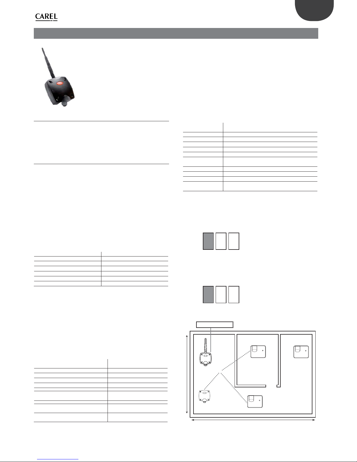
39
ENG
“Wireless probes” +0300030EN - rel. 1.0 - 16.07.2010
9.1 Parameters and functions
For each Router in the network, the information listed in the table can be
identi ed from the noti cation messages sent by the Router to the Access
Point, updated at intervals established by parameter HR_05 on the Access
Point (default 20s).
9.2 Binding the Router to the Access Point
• Open the domain on the Access Point (press button T1 once).
• Power up the Router.
• The button on the Router does not need to be pressed, if the device is free
the procedure is activated automatically.
• All the LEDs come on steady.
• The Router searches for an Access Point to connect to (all the LEDs ash
every 20s).
• Binding is successfully completed when only LED L1 remains on ashing,
the Router is now connected to the Access Point.
• The Router address is set automatically and sequentially by the Access Point
when it’s added to the network, assigning the network addresses from 200
to 247 for a maximum of 48 devices. This is valid for all Routers (including
the Router-Bridge and EP1 Router-Sensor, etc.). A maximum of 60 Routers
can be added.
• The commissioning procedure is now complete and the system is ready to
communicate data.
Adr #200 Slot 1st Router added to the network
Adr #201 Slot 2nd Router added to the network
Adr #202 Slot 3rd Router added to the network
Adr #203 Slot 4th Router added to the network
Adr #204 Slot 5th Router added to the network
Adr #200+(i-1) Slot i-th Router added to the network
Adr #247 Slot 48th Router added to the network
Tab. 9.a
NOTE: the binding operation on the Router may fail if:
• Distances are excessive;
• Infrastructure is present that prevents communication between the devices;
Each sensor installed should be visible to at least 2 devices, either Access Point
or Router. In the event of faults on the Router or additional barriers that block
the wireless signal, the sensor will nd an alternative route to communicate
with the Access Point.
Table of alternative addresses associated with the Router
Check the settings on the Access Point described in the chapter “Setting
operating mode”
InputRegister[1000] - InputRegister[1011]
Slot 1st Router added to the
network
InputRegister[1012] - InputRegister[1023]
Slot 2nd Router added to the network
InputRegister[1024] - InputRegister[1035]
Slot 3rd Router added to the network
InputRegister[1036] - InputRegister[1047]
Slot 4th Router added to the network
InputRegister[1048] - InputRegister[1059]
Slot 5th Router added to the network
InputRegister[1000+12*(i-1)] InputRegister[1011+12*(i-1)]
Slot i-th Router added to the network
InputRegister[2524] - InputRegister[2535]
Slot 128th Router added to the
network
InputRegister[…0]
Entry status (0xFF=slot empty; 0=Router timeout; 1=Router on)
Tab. 9.b
Router information table
InputRegister[…1] Type of device (e.g.: 101=Router ZR-BR-xx; 108=Router
ZR-REP-xx)
InputRegister[…2] Firmware version
InputRegister[…3] Router EUI64 (bytes 0, 1)
InputRegister[…4] Router EUI64 (bytes 2, 3)
InputRegister[…5] Router ShortID
InputRegister[…6] Cost (distance from the Gateway in terms of hops)
InputRegister[…7] RSSI of the last message received by the Router
(db+100)
InputRegister[…8] Number of Routers
InputRegister[…9] Number of “good” Router neighbours
InputRegister[…10] Number of Router End-Device children
InputRegister[…11] Counter of presence messages sent by the Router and
received by the Gateway
Tab. 9.c
Make sure that the serial address associated automatically and sequentially is
not in con ict with another device already associated with the network.
Binding the Routers
OPEN DOMAIN: press button T1 on the Access Point. LED L1 will start ashing
quickly (0.25s).
1 2 3
New devices can now be added;
Power up the Router and wait for LED L1 to ash;
CLOSE DOMAIN: After having added all the required devices, press button T1
on the Access Point to close the domain (LED L1 starts ashing again (1s) on
the Router and the Access Point.
1 2 3
NOTE: The domain closes automatically 15 minutes after last opening;
Access point
S1
S2
S3
S4
RS485 Modbus RTU
30 m
30 m
Fig. 9.b
9. RO ROUTER
This is a device that repeats the wireless signals so as to cover greater distances between the Access Point and the sensors. As soon as it
detects a wireless signal recognised by the network, it relays it.
In addition, it can be used to expand the number of sensors connected to the Access Point when these exceed 30 units, or if the distance
is greater than 30 m.
Fig. 9.a

40
ENG
“Wireless probes” +0300030EN - rel. 1.0 - 16.07.2010
9.3 Resetting the device
To reset the device, proceed as follows..
Make sure that there are no Access Points with the network open in the
vicinity. Press and hold button T1 until the pairs of LEDs L1-L2 and L2-L3 ash
alternately.
1 12 23 3
Release the button. LEDs L1, L2 and L3 will ash brie y a few times and all three
switch o (reset completed).
Warning!!!
Resetting the Router does not reset the serial address assigned automatically
by the Access Point if connected again to the same AP within 2 hours. If bound
to another network, it behaves like a new Router and consequently the rst
available address will be assigned (if previously reset).
9.4 Table of LED status
LEDs in normal
operation
Action Meaning of the signal
LED L1 Operation slow ash (1Hz) network Access
Point closed
quick ash (4Hz) network Access
Point open
LED L2 Wireless link
o No Router with good
connection in the vicinity
1. ash Router with good
connection in the vicinity
2. ashes two Routers with
good connection in the
vicinity
3. ashes four or more
Routers with good connection
in the vicinity
LED L3 Wireless activity
1. Normally o .
2. On when sending or receiving
a wireless message.
Tab. 9.d

41
ENG
“Wireless probes” +0300030EN - rel. 1.0 - 16.07.2010
10. ROUTERS WITH OTHER INTEGRATED FUNCTIONS
10.2 RB Router-Bridge
The Router-Bridge is used to connect a local Modbus RTU network of Carel
or third party devices when needing to supervise instruments via a wireless
network. The address setting and reset procedures are the same as described
for the Router.
The following approved devices can be connected to the local network::
• Gavazzi CPT-DIN / WM14;
• Gavazzi WM14;
• IR33 Modbus® IR33C0HB0M.
The devices described above have been checked with the PVPRO supervisor
as shown below. Operation of the devices outside of the limits indicated or
with others supervisors is not guaranteed.
1. Limits in message sizes. Responses must not exceed 52 bytes; this implies
that no more than 26 registers (holding registers or input registers) can be
read with one single message;
2. Query frequency. The time interval between receiving a response and the
following query must not be less than one second;
3. Communication timeout. The time interval between two consecutive queries
before a response is received must not be less than 3 seconds. This means a
communication timeout of at least 3 seconds.
Dipswitches 1 to 4 are used to set the operating features of the local Modbus
RS485 serial connection.
DIP1 DIP2 DIP3 DIP4 Speed Parity Stop Bits
OFF OFF OFF OFF 9600 none 2
ON OFF OFF OFF 19200 none 2
OFF ON OFF OFF 9600 even 2
ON ON OFF OFF 19200 even 2
OFF OFF ON OFF 9600 none 2
ON OFF ON OFF 19200 none 2
OFF ON ON OFF 9600 odd 2
ON ON ON OFF 19200 odd 2
OFF OFF OFF ON 9600 none 1
ON OFF OFF ON 19200 none 1
OFF ON OFF ON 9600 even 1
ON ON OFF ON 19200 even 1
OFF OFF ON ON 9600 none 1
ON OFF ON ON 19200 none 1
OFF ON ON ON 9600 odd 1
ON ON ON ON 19200 odd 1
Tab. 10.a
• Limits for correct serial communication management:
• Message size max 52 bytes.
• Query frequency min 1 second
• Communication timeout min 3 seconds
Installation example of the Router-Bridge and EP1 Router-Sensor in a network with other wireless devices
Fig. 10.a
Other Router devices are available that integrate the following functions:
• EP1 Router-Sensor (with two analogue and two digital inputs, the same
operation as the EP SE Sensor battery version);
• RB Router-Bridge (to extend a Modbus RS485 local network, connecting
other devices);
• RA Router-Actuator (I/O module with thermostat function);
• RC Router-Pulse Counter (same operation as the CI Pulse Counter battery
version);
The address setting and reset procedures as the same as described for the
Router.
The dipswitches on the device are used to set the address for the integrated
functions. Consequently each device has two network addresses: the Router
address assigned automatically by the Access Point, and the device address
selected by dipswitch (excluding the Router-Bridge). For complete supervision
of the devices, both network addresses must be monitored;
10.1 EP1 Router-Sensor
The EP1 Router-Sensor has 2 probe inputs and 2 digital inputs, and features
the same functions and same parameters as the EP SE Sensor battery version.
It is used in all applications requiring monitoring of digital inputs that change
frequently and where the life of the battery version would be too short (each
opening and closing of the digital contact causes wireless communication to
update the parameters).
For the features, operating modes and supervision, see this manual under the
section on the EP SE Sensor.
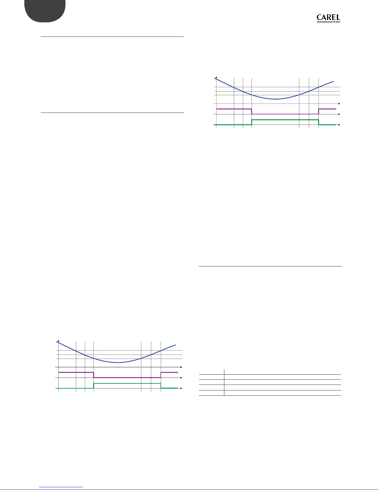
42
ENG
“Wireless probes” +0300030EN - rel. 1.0 - 16.07.2010
10.3 RA Router-Actuator
The Router-Actuator is a device featuring:
• 1 NTC probe input 10K@25°C
• 2 two digital inputs;
• 2 digital outputs;
The device implements a thermostat function with programmable heating/
cooling mode, relay outputs and alarm management based on set thresholds.
Alternatively, the control function can be disabled and inputs and outputs
managed directly by the supervisor or via Modbus® controller.
10.4 Functions implemented
Analogue temperature input management
The device acquires the temperature via the analogue input using an external
probe with sampling once a second (probe 10K@25°C Beta=3435K). The
operating range is -50T90°C. When the temperature values are outside of
these limits, the device signals an alarm:
• +100 probe input short-circuited;
• -50 probe input open;
Temperature alarm management
The device compares the temperature measured by the reference probe
against the parameters that de ne the alarm limits.
There are no delays in activating the alarm signal; as soon as the acquired value
is higher than the maximum limit or lower than the minimum limit the alarm
is activated.
If Temperature > High temperature limit --> high temp. alarm =1
If Temperature ≤ High temperature limit --> high temp. alarm =0
If Temperature < Low temperature limit --> low temp. alarm =1
If Temperature ≥ Low temperature limit --> low temp. alarm =0
If the probe input is short-circuited (signal equal to +100.0°C), as well as the
probe fault alarm, the high temperature alarm is also activated.
If the probe input is open (signal equal to -50.0°C), as well as the probe fault
alarm, the low temperature alarm is also activated.
Control management (digital outputs)
The control process is managed based on the Control mode parameter.
Mode =0
Control is disabled and both relays are deactivated.
Mode =1 (Cool)
Control is performed as follows:
High threshold = Set Point + Hysteresis/2
Low threshold = Set Point - Hysteresis/2
If Temperature > High threshold --> Relay 1 On ; Relay 2 O
If Temperature < Low threshold --> Relay 1 O ; Relay 2 On
set+Hys/2
set-Hys/2
Relay 1
Relay 2
Regulation for mode= 1 (cooling)
Fig. 10.b
Mode =2 (Heat)
Control is performed as follows:
High threshold = Set Point + Hysteresis/2
Low threshold = Set Point - Hysteresis/2
If Temperature > High threshold --> Relay 1 O ; Relay 2 On
If Temperature < Low threshold --> Relay 1 On ; Relay 2 O
set+Hys/2
set-Hys/2
Relay 1
Relay 2
Regulation for mode= 2 (heating)
Fig. 10.c
Control in the event of probe faults
In the event of a probe fault control is disabled and both relays are deactivated.
Mode =3 (Manual)
In this mode the state of the relay is controlled by CS_01 and CS_02.
Mode =4 (Manual with button input)
In the same way as for mode 3, the relays are controlled by CoilStatus[1] and
CoilStatus[2].
In addition, the state of relay 1 is also controlled by a button connected to
digital input IN_1 and relay 2 by a button connected to digital input IN_2.
Operating the button reverses the logic of the related output.
Mode =5 (Manual with switch input)
In the same way as for mode 3, the relays are controlled by CoilStatus[1] and
CoilStatus[2].
In addition, the state of relay 1 is also controlled by a button connected to
digital input IN_1 and relay 2 by a button connected to digital input IN_2.
Operating the button reverses the logic of the related output.
10.5 RC Router-Pulse Counter
The RC Router-Pulse Counter has 2 digital inputs and 2 probe inputs, and the same
functions and same parameters as the CI Pulse Counter battery version.
It is used in all applications that require monitoring of electricity, water and gas
consumption when the digital inputs have a high switching frequency (the life of
the battery version would be too short, as each opening and closing of the digital
contact causes wireless communication to update the parameters).
The data are saved to static memory every 6 hours, in the same way as the battery
version, and in the event of power failures the data is retained in the memory
without loss.
For the features, operating modes and supervision, see this manual under the
section on the CI Pulse Counter..
Special commands – Command password
The special commands can be used to activate certain functions on the devices
via the wireless network.
The command is executed when parameter CS_00 is set to 1.
HR_00 (HEX) HR_00 (DEC) Action
0x01F5 501 Delete Pulse Counter IN_1
0x01F6 502 Delete Pulse Counter IN_2
0x01F7 503 Set Counter IN_1 with value for Password 2,3
0x01F8 504 Set Counter IN_2 with value for Password 2,3
Tab. 10.b

43
ENG
“Wireless probes” +0300030EN - rel. 1.0 - 16.07.2010
10.6 Technical speci cations
Product code
RO Router
Code WS01RC1M20
EP1 Router-Sensor
Code WS01VB2M10
RB Router-Bridge
Code WS01RB2M20
Router-Actuator
Code WS01H02M20
Route-Pulse counter
Code WS01N02M20
Power supply For 12-24 Vac/dc ±10% 100mA 50/60 Hz versions use a class II safety transfor-
mer with minimum power rating 2 VA. 12 Vac transformer recommended
Router 230 Vac,
Italian plug f
or 230 Vac mains
12-24 Vac/dc ±10%
100mA; 50/60 Hz;
12-24 Vac/dc ±10%
100mA; 50/60 Hz;
24 Vac/dc ±10%
100mA; 50/60 Hz;
12-24 Vac/dc ±10%
100mA; 50/60 Hz;
Maximum power input 1 VA
x xxxx
Radio frequency speci cations Frequency: selectable from 2405 to 2480 MHz (by parameter or automatically,
see Table of supervisor parameters)
Wireless protocol: ZigBee
x xxxx
Power transmitted
+10dB +10dB 0dB +10dB +10dB
Operating conditions -40T50°C, <80% RH non-condensing x xxxx
Storage conditions -20T70°C, <80% RH non-condensing
Connections - screw terminals for 12.24 Vac/
dc power supply
Power supply terminal: plug-in cables max size 1.5 mm
- xxxx
230 Vac version connections
cable
L=1.5mItalian
plug
----
Type of cable for serial connection Shielded cable max length 1000 m
Range of temperature reading for NTC probes
1 and 2
-50T90°C, <80% RH non-condensing
- -x--
Precision of temperature measurement ± 1 °C -10T30°C; ± 2 °C -30T40°C
- x-x-
Temperature measurement inputs Measurement from -50 to + 90 C. Resolution 0.1 C. Compatible
with standard CAREL probes 10 KOhm @25C (B3435)
- -x--
Digital inputs For voltage-free contacts (isolated) - Closing current 0.01mA. Use self-cleaning
contacts (Open connector transistor or Reed Switch).
- -x--
Assembly wall-mounted by screws
- -x--
Display/Con guration Read and write parameters via RS485
- -x--
Protocol Modbus
- -x-Index of protection IP55 (see note 1)
Classi cation according to protection against
electric shock
Can be integrated into class I or class II appliances
Environmental pollution Normal
PTI of insulating materials 250 V
Period of stress across the insulating parts Long
Category of resistance to heat and re category D (box and cover)
Immunity against voltage surges category 2
Software class and structure Class A
Disposal Obser ve local legislation for the disposal of electrical material
Accessories TRASP3E120 – Plug-in transformer 3VA 230-12Vac
TRADR4W012 - Electrical panel transformer 3VA 230-12Vac
Tab. 10.c
Key:
x Included
-
Not featured
Note: The index of protection is maintained only if a cable with an outside
cross-section of less than 8 mm is used.
10.7 List of Router system variables
(alphabetical order)
AP_RX_RADIO_LEV RSSI of the last message received from the Gateway. Indicates the wireless signal level between the router and Access Point or Router. For further
information see Z-Con g;
CONNECTED_UNIT Number of units (end devices) connected to the repeater;
FW_VERSION FW revision
MAC_ADDR_0 Unique 32 bit unit identi er (1=MSB, 0=LSB). Uniquely identi es each device
MAC_ADDR_1 Unique 32 bit unit identi er (1=MSB, 0=LSB). Uniquely identi es each device
MACHINE_CODE Supervisor peripheral identi er;
NET_PANID De nes the device address for operation inside the network.
ON_LINE_STATUS Indicates the entry status (0xFF=slot empty; 0=Router timeout; 1=Router on);
QUALIY_CONN_SIGNAL Parameter for internal use;
ROUTER_GOOD_SIGNAL Number of nearby routers with a good wireless signal ≥ 30dB;
ROUTER_NEARBY Number of nearby Routers. Indicates the number of routers near the device;
RX_MESSAGE_CNT Parameter for internal use to check the wireless network;
Tab. 10.d

44
ENG
“Wireless probes” +0300030EN - rel. 1.0 - 16.07.2010
10.8 List of Router parameters
The following parameters are valid for the RO Router as well as for the Router function on the following devices:
• EP1 Router-Sensor;
• RB Router-Bridge;
• RA Router-Actuator;
• RC Router-Pulse Counter
Variable Index Name Description Def. Min Max UoM “Type R/W”
IR0 ‘ON_LINE_STATUS’ ‘Slot status (0xFF=empty; 0=time out; 1=on)’ - 0 1 - R
IR1 ‘MACHINE_CODE’ ‘Unit type - machine code (es: 101=Router Bridge 12..24Vac/dc; 108=Router 230Vac)’ 101/108 - - - R
IR2 ‘FW_VERSION’ ‘Firmware version (Major/Minor)’ 2051 - - - R
IR3 ‘MAC_ADDR_0’ ‘Units unique identi er Mac-Address LSB’ - 0 65535 - R
IR4 ‘MAC_ADDR_1’ ‘Units unique identi er Mac-Address MSB’ - 0 65535 - R
IR5 ‘NET WORK_ID’ ‘Network address ‘ - 0 65535 - R
IR6 ‘QUALIY_CONN_SIGNAL’ ‘Quality signal (internal use)’ - 0 255 - R
IR7 ‘AP_RX_RADIO_LEV’ ‘Radio Lev. for AP Rx messages’ - 0 100 dBm+100 R
IR8 ‘ROUTER_NEARBY’ ‘Number of Routers nearby’ - 0 16 - R
IR9 ‘ROUTER_GOOD_SIGNAL’ ‘Number of Router nearby with good connection’ - 0 16 - R
IR10 ‘CON NECTED_UNIT’ ‘Number of Connected units (On-line units) End Devices to Router’ - 0 32 - R
IR11 ‘RX_MESSAGE_CNT’ ‘Counter - AP Rx messages’ - 0 65535 - R
Tab. 10.e
10.9 List of RA Router-Actuator parameters
Variable Index Name Description Def. Min Max UoM “Type R/W”
HR0 CMD_PASSW_1 ‘Command Password (1) ‘ 0 0 65535 - R/W
HR1 TRANSM_CYCLE ‘TX data cycle time ‘ 20 5 3600 sec R/W
HR2 LO_TEMP_TRESHOLD ‘Threshold low Temp. ‘ 0 -500 500 0,1°C R/W
HR3 HI_TEMP_TRESHOLD ‘Threshold high Temp. ‘ 300 -500 500 0,1°C R/W
HR4 HYSTERESIS_SET ‘Hysteresis ‘ 20 10 100 0,1°C R/W
HR5 SET_POINT ‘Set point ‘ 200 -500 500 0,1°C R/W
HR6 MODE ‘Operating mode (0=o ; 1=cool,; 2=hot; 3,4,5= manual) ‘ 0 0 5 - R/W
IR0 MACHINE_CODE ‘Unit type - machine code ‘ 69 - - - R
IR1 FW_VERSION ‘Firmware version (Major/Minor) ‘ 2051 - - - R
IR2 TX_MESSAGE_CNT ‘Total Number of TX radio messages ‘ 0 0 65535 - R
IR3 RX_MSG_LEVEL ‘Radio signal Level ‘ - 0 100 dBm+100 R
IR4 TEMPERATURE ‘Temperature Value ‘ - -500 1000 0,1°C R
IR5 MAC_ADDR_0 ‘Unit unique identi er Mac-Address LSB ‘ - 0 65535 - R
IR6 MAC_ADDR_1 ‘Unit unique identi er Mac-Address MSB ‘ - 0 65535 - R
IR7 ID_SER_ADDR ‘Carel_ID, Serial_Address, DIP-SW value ‘ - 16 127 - R
IR8 LAST_RX_DELAY ‘Time from last AP Rx message ‘ - 0 65535 - R
IR9 RX_MESSAGE_CNT ‘Counter - AP Rx messages ‘ - 0 65535 - R
IR10 TIME_STAMP ‘Time stamp for Temp. readings (100*hour+minute) ‘ - 0 2359 hh*100+mm R
IR11 AP_RX_RADIO_LEV ‘Radio Lev. for AP Rx messages ‘ - 0 100 dBm+100 R
IR12 NETWORK_ID ‘Network address ‘ - 0 65535 - R
IR13 ‘MIRROR_IS’ ‘Mirror Input Status (internal use)’ - 0 65535 - R
CS0 EN_CMD_PW ‘Trig. PWD (internal use) ‘ 0 0 1 - R/W
CS1 SET_RELE1 ‘Setting of relay 1 (operating mode = 3 manual) ‘ 0 0 1 - R/W
CS2 SET_RELE2 ‘Setting of relay 2 (operating mode = 3 manual) ‘ 0 0 1 - R/W
CS3 IN_1_POL ‘IN_1 Digital input polarity ‘ 0 0 1 - R/W
CS4 IN_2_POL ‘IN_2 Digital input polarity ‘ 0 0 1 - R/W
CS5 EN_NTC ‘Enable Probe NTC ‘ 1 0 1 - R/W
IS0 HI_TEMP_ALARM ‘High Temperature Alarm ‘ - 0 1 - R
IS1 LO_TEMP_ALARM ‘Low Temperature Alarm ‘ - 0 1 - R
IS2 RELE1_STATUS ‘Status Relay 1 ‘ - 0 1 - R
IS3 RELE2_STATUS ‘Status Relay 2 ‘ - 0 1 - R
IS4 IN_1_STATUS ‘Digital Input State IN_1 (1=open CA, 0=closed CC) ‘ - 0 1 - R
IS5 IN_2_STATUS ‘Digital Input State IN_2 (1=open CA, 0=closed CC) ‘ - 0 1 - R
IS6 PROBE_ERROR ‘Probe Failure Alarm ‘ - 0 1 - R
Tab. 10.f
Key:
HR = Holding register
IR = Input register
CS = Coil Status
IS = Input Status
10.10 Installation notes
1. Remove the cover;
2. Fasten the case to the wall with minimum two screws, remembering that this is a radio device and therefore the necessary details must be observed.
3. Connect::
- Power supply;
- NTC temperature sensors (10K@25°C Beta(25/85) = 3435K) (models where featured);
- Digital inputs (models where featured);
- Analogue input (models where featured);
4. Select the network address by dipswitch (for versions that feature the integrated functions).
5. Open the Access Point wireless network (binding is performed automatically).
6. Check the quality of the wireless signal.
7. Close the device again.
8. Make sure that the transmitter is in an optimum position with reference to the receiver, once installation is complete, checking the transmitted signal level in
the corresponding supervisor variable.
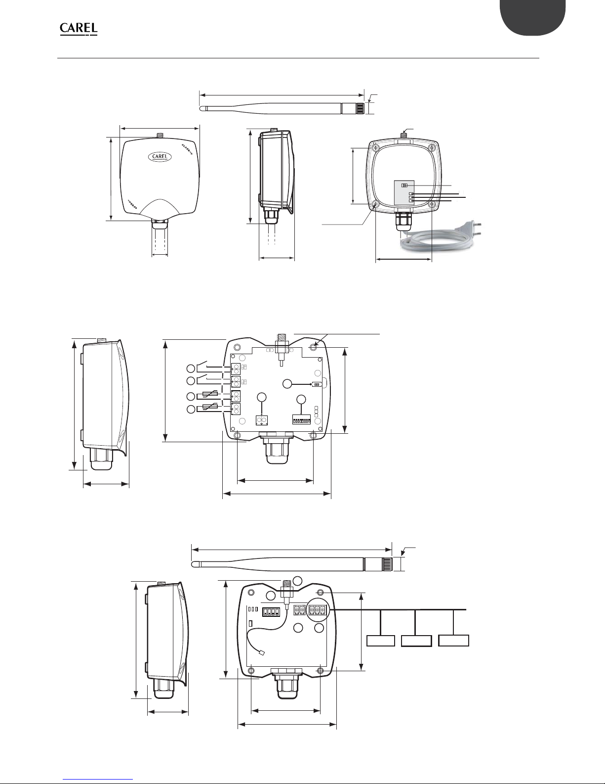
45
ENG
“Wireless probes” +0300030EN - rel. 1.0 - 16.07.2010
10.1 Electrical connections and physical dimensions
• RO Router 230 Vac ver.
72
fori di ssaggio
mounting holes
98
105
PG9
CH19
108
44
T1
L1
L2
L3
2
72
196
13
T1
L
1
L2
L3
2
7
2
1
3
Fig. 10.d
If the device is used with a di erent power outlet, cut the cable and connect a plug that meets requirements.
• EP1 Router-Sensor
94
102
50
70
40
108
1
2
4
3
7
- +
5
L2
L3
1
8
6
fori di ssaggio / mounting holey
L1
Fig. 10.e
• RB Router-Bridge
40
108
196
13
94
102
50
DIP: 1 2 3 4
++
G
--
Rx- Rx+GND
L1
L2 L3
70
T1
ON
Remote serial line RS485 Modbus
£
Device 1
Device 2
Device 3
1
2
4
3
Fig. 10.f
1. Probe input NTC_110K@25°C Beta(25/85) = 3435K
(e.g. NTC*HP* or NTC*WP*);
2. Probe input NTC_2 10K@25°C Beta(25/85) = 3435K
(e.g. NTC*HP* or NTC*WP*);
3. Defrost digital input (IN_1) can be con gured N.C. or N.O;
4. Door digital input (IN_2) can be con gured N.C. or N.O;
5. Binding/unbinding button;
6. Dipswitches for setting serial address;
7. 12-24 Vac/dc power supply
The maximum cable length for NTC probes and digital
inputs is 10 m.
1. 12 Vac/dc power supply;
2. Modbus® RS485 serial connection;
3. Dipswitches for serial address;
4. Antenna.
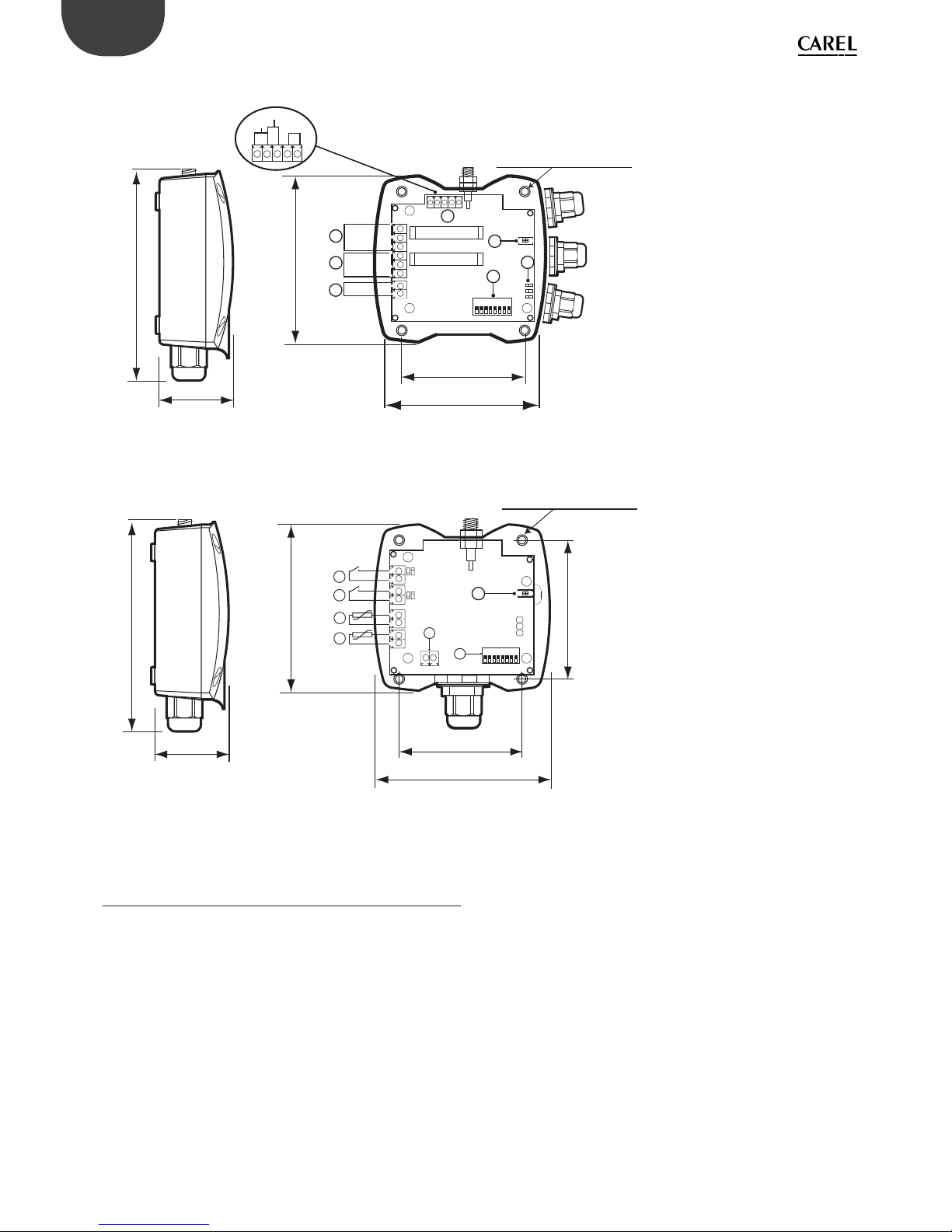
46
ENG
“Wireless probes” +0300030EN - rel. 1.0 - 16.07.2010
• RA Router-Actuator
102
40
108
fori di ssaggio / mounting holey
50
94
1
2
3
5
6
1
8
L1
L2
L3
7
4
IN_2
IN_1
NTC
NO
C
NC
NO
C
NC
Fig. 10.g
• RC Router-Pulse Counter
94
102
40
108
50
70
fori di ssaggio / mounting holey
3
4
2
1
6
L1
L2
L3
7
- +
5
8
1
ON
Fig. 10.h
Note: all the measurements are in mm.
1. 12... 24 Vac/dc power supply;
2-3 SPDT relay output;
4. I/O (digital & analogue inputs);
5. Binding/unbinding button;
6. Con guration dispswitches;
7. LEDs.
1. Pulse counter digital input 1 (IN_1);
2. Pulse counter digital input 2 (IN_2);
3. Probe input NTC_1 10K@25°C Beta(25/85) = 3435K
(e.g. NTC*HP* or NTC*WP*);
4. Probe input NTC_2 10K@25°C Beta(25/85) = 3435K
(e.g. NTC*HP* or NTC*WP*);;
5. Binding/unbinding button;
6. Dipswitches for setting serial address;
7. 12-24 Vac/dc power supply
The maximum cable length for NTC probes and digital
inputs is 10 m.
10.11 General warnings
Fasten the device to the wall with the cable gland facing downwards;
Tighten the antenna in its housing (4), and position it vertically to the oor;
Connect the power supply to the terminal (1), ensuring the polarity indicated
for DC power supply (12 to 24 Vac/dc version).
A 12 Vac transformer is recommended for the device 12-24 Vac versions.
For correct operation the system must be powered at all times, in the event
of power failures there may be a unit reset time (OFFLINE) based on the data
transmission cycle.
IMPORTANT:
If the same power supply is shared by more than one unit, connect the same
wire from the transformer to the power supply “-” terminal (1).

47
ENG
“Wireless probes” +0300030EN - rel. 1.0 - 16.07.2010
11.3 Wiring
To wire the serial connection to the Access Point or Router-Bridge local RS485
network, use 3-wire shielded cable. To ensure IP55 protection on the case, use
a 5-wire cable, and relay the serial and power supply connections through an
external junction box with terminal block.
The maximum wire size for the terminals is 1.5 mm2. The maximum outside
diameter of the cable must not exceed 8 mm, to allow it to pass through the
cable gland.
Features of the serial connection cable
For connection to the Access Point, the cable used must have the following
characteristics:
Twisted pair;
Shielded, preferably with earth wire;
Size AWG20 (diam. 0.7-0.8 mm; area 0.39-0.5 mm);
Make sure that the cable shield is connected to EARTH on the supervisor
connection side, and that the polarity of the connection is observed on all
the units connected. The shield is normally connected to the reference on all
the units.
Also pay careful attention when connecting the local network to the RouterBridge, when using controllers connected in a local Modbus® RS485 network.
11. GENERAL NOTES
11.1 Notes for correct installation
• To ensure correct operation of the ZigBee wireless system, the best possible
connection must be guaranteed between the Access Point and the Router.
• The Router should preferably be installed at a height of around 2 to 3 m
from the oor, not in contact with large metallic objects (air ducting etc.), so
as to avoid the Router-Access Point connection being a ected by obstacles
such as cabinets, showcases, moving people, and where possible in direct
line of sight with the other devices.
• Make sure that the path between the Router and the Access Point does not
include metallic re doors or large metallic obstacles (elevator compartment
etc.) which may disturb the connection.
• When positioning the devices, check that the sensors have at least two
wireless routes to the Access Point; that is, they can be seen by at least
two Routers or one Router and the Access Point, and that the wireless
signal levels, both in and out, are good. Remember that wireless devices
are signi cantly a ected by changing environmental conditions, unlike
wired connections, and therefore each sensor should be able to reach
the Access Point via at least two devices connected at the same wireless
network, which may be an Access Point and Router, or two Routers. It’s also
recommended to set a delay on the supervisor (around 1 hour) for notifying
alarm signals, so as to avoid false sensor o ine warnings;
• Fasten the Access Point/Router in position, considering that as the device
being installed is a radio device, the following simple rules must be
observed:
• The e ciency of radio transmission is reduced when there are obstacles,
metal shelving or other objects that may block the reception of the wireless
signals;
• If the product is wall-mounted, fasten it to a masonry wall rather than a
metal wall, to improve the range of the signal;
• Like all radio equipment, avoid installing the Access Point near other
electronic appliances, so as to avoid interference;
• Connect the RS485 network to the terminal respecting the polarity.
• For correct operation the system must be powered at all times, in the event
of power failures there may be a unit reset time (OFFLINE) based on the data
transmission cycle;
• Do not install the instruments in environments with the following
characteristics:
• Strong vibrations or knocks;
• Exposure to water sprays;
• Exposure to direct sunlight or the elements in general;
If the devices are used in a way that is not described by the manufacturer, the
speci ed level of protection may be a ected.
11.2 Power supply connection
The 12-24 Vac/dc Access Point and Router can be powered using the CAREL
230/12 Vac 3 VA plug-in transformer code TRASP3E120, or electrical panel
transformer code TRADR4W012, or any other 12 Vac 2 VA transformer.
For 12/24 Vac/dc versions, the maximum wire size for the terminals is 1.5 mm2.

48
ENG
“Wireless probes” +0300030EN - rel. 1.0 - 16.07.2010
12. RTM SE HANDHELD
12.1 General Features
The rTM SE ZigBee handheld is a very useful device for the installation,
control and maintenance of networks of rTM SE system wireless devices. It
is not needed however for normal operation of the wireless network devices
(sensors, Access Points, Routers).
For a limited operating period inside the network, the handheld represents
a Router-like node on which the normal wireless tra c relaying functions
are disabled. Its function is essentially to identify the wireless signal level in
the area where the Sensor or Router-Bridge is being installed, so as ensure
these are reached by the wireless signal, checking the signal level and how
many receiving devices can be connected. In other words it identi es whether
the position chosen for the installation of a new Sensor or Router is suitably
covered by the wireless signal in question.
The rTM SE handheld also provides the following functions:
• Open and close the wireless network on the Access Point in order to bind
other sensors, without having to press the local button on the Access Point
or access it via the supervisor;
• Reset Routers and Access Points associated with the wireless network;
• Set the address of BP Sensors after binding these to an Access Point;
Security of these operations is guaranteed by the network password that can
be set on the rTM SE handheld.
It is consequently a tool that signi cantly simpli es the installation of the rTM
SE system.
“Function A” button
“Function B” button
“Function C” button
“Function D” button
“Function 1” button
“Left” button
“OFF” button
“UP” button
“DOWN” button
“Right” button
“Function 3” button
NOT USED BUTTONS
“Function 2” button
Fig. 12.a
12.2 Operating modes
The rTM SE handheld features two main operating modes:
• Not connected
the rTM SE handheld is not connected to any wireless network; in this case,
it may try to connect to a network or alternatively can scan the ZigBee
wireless channels.
Functions available in this mode:
- Scan energy (“Ener.Scan” menu)
- Scan networks (“Netw.Scan” menu)
- Scan connection (“Join Scan” menu)
• Connected to a network
the rTM SE handheld is connected to a compatible network (Modbus /
Carel); Only in this case can it activate the test function (Ping Test). Functions
available in this mode:
- Ping test
- Network functions (“Commands” menu)
- Unbinding (“Leave Net” menu)
12.3 Main menu
The structure of the main menu on the rTM SE handheld depends on the operating
mode that is currently active and re ects the list of the functions described above.
• Main menu - not connected
Z-HANDHELD
ZB-CAREL
Node
Not Joined
>Netw.Scan
>Join Scan
Press
>Ener.Scan
Fig. 12.b
• Main menu - connected to a network
Z-HANDHELD
ZB-CAREL
Node
Joined
Channel 23
Pan 0x15B3
0x803EA00F
D007E803
>Commands
>Leave Net
Press
>Ping Test
Parameters for the
network the rTM SE
handheld is connected to
Fig. 12.c
In both cases, press the “Up” and “Down” buttons to scroll the menu; press the
“Right” button to activate the selected function.
Adjusting contrast of the LCD
When the main menu is active (in either mode), pressing the “function 1”
button reduces the contrast of the LCD; vice-versa pressing the “function 2”
button increases contrast.
12.4 Scan Energy
The scan energy process measures the maximum RSSI value (Received Signal
Strength Indication) on each of the 16 wireless channels.
This value provides an indication of the degree of disturbance on each
channel. The entire process lasts around one minute.
ENERGY
SCANNING
Waiting
for
Process
Completion
ENERGY
SCANNING
Press
Ch Energy
12
13
14
15
16
17
18
19
20
21
Z-HANDHELD
ZB-CAREL
Node
Not Joined
>Ener.Scan
>Join Scan
Press
>Netw.Scan
Fig. 12.d
Press the “up” and “down” buttons to scroll the values of all the channels,
displayed in order. Press the “Left” button to return to the main menu.
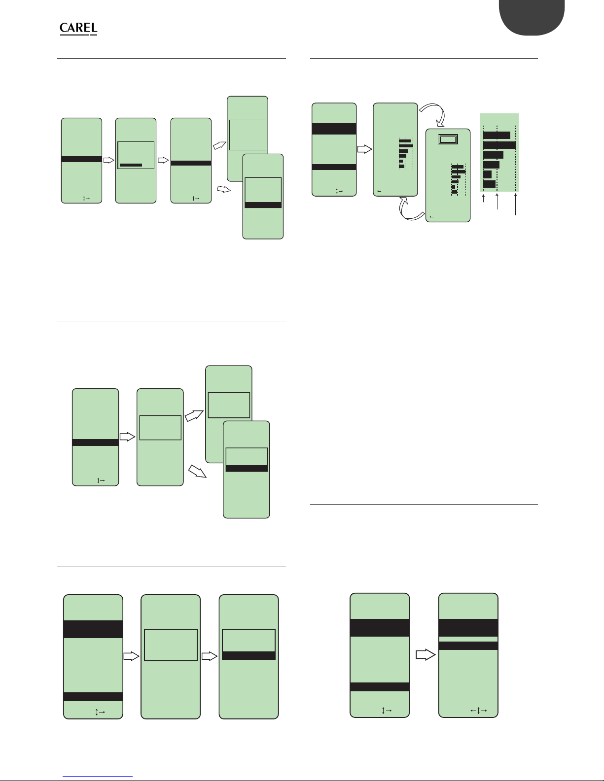
49
ENG
“Wireless probes” +0300030EN - rel. 1.0 - 16.07.2010
12.5 Scan Networks
The scan networks process analyses all 16 wireless channels to search for
ZigBee networks. The process lasts around 20 seconds. At the end of the
process, the list of networks detected is displayed.
Z-HANDHELD
ZB-CAREL
Node
Not Joined
>Ener.Scan
>Join Scan
Press
>Netw.Scan
NETWORKS
SCANNING
NETWORKS
SCANNING
Waiting
for
Process
Completion
Press
Detect:5
Ch PanID
13 0x0212
14 0x3337
21 0x3333
>23 0x15B3
24 0x1223
Join
attempt
to Network
Channel 23
Pan 0x15B3
Error!!
Press
Press Key
Join
attempt
to Network
Channel 23
Pan 0x15B3
Success!
Fig. 12.e
Press the “up” and “down” buttons to select the desired network. Press the
“Right” button to attempt to connect to the selected network. Press the “Left”
button to return to the main menu.
12.6 Scan Connection
The scan connection process analyses all 16 wireless channels to search for a
compatible open network. If a network with the required features is detected,
the binding procedure is activated. The whole process lasts a maximum of
around 25 seconds.
Z-HANDHELD
ZB-CAREL
Node
Not Joined
>Ener.Scan
Press
>Netw.Scan
Join
Scanning
Process
waiting..
Join
Scanning
Process
Error!!
Press
>Join Scan
Press Key
Join
Scanning
Process
Succes!
Fig. 12.f
12.7 Unbinding
The unbinding process disconnects the rTM SE handheld from the network it
was previously bound to.
Z-HANDHELD
ZB-CAREL
Press
Leaving
Network
Process
waiting..
Press Key
Node
Joined
Channel 23
Pan 0x15B3
0x803EA00F
D007E803
>Commands
>Leave Net
>Ping Test
Leaving
Network
Process
Success!
Fig. 12.g
12.8 Ping test
The Ping Test is the main function of the rTM SE handheld. It’s used to identify
the Routers that are operating within the operating range in the bound
network. For each Router the two least signi cant digits of the unique device
address (MAC ADDRESS) are shown, along with the signal level (RSSI).
Z-HANDHELD
ZB-CAREL
>Commands
>Leave Net
Press
>Ping Test
Ping Test
Channel 23
Pan 0x15B3
0x803EA00F
D007E803
to esc
Nodes 6
MAC A Rssi
9FA1
E15F
E152
2001
2801
*0901
Node
Joined
PING
to esc
Nodes 6
MAC A Rssi
9FA1
E15F
E152
2001
2801
*0901
Rssi
Dettaglio indicazioni del segnale
Datails of signal-levels
-90 dB
-80 dB
-60 dB
Fig. 12.h
Warning. Due to the reduced space available on the rTM SE handheld display,
only the last 4 digits (LSB) of the MAC ADDRESS are displayed.
During this operation, the rTM SE handheld sends a wireless message to all
the Router nodes in its operating range at regular 3 second intervals (unit
range broadcast).
This event is highlighted by the “PING” message at the top of the display. The
Router devices that receive the message respond with a message sent to the
rTM SE handheld containing their address. The messages received by the rTM
SE handheld are used to constantly update the values displayed.
The Ping Test lasts four minutes, after which the main menu is automatically
displayed. Alternatively, the Ping Test can be ended by pressing the “Left”
button. Pressing any other button repeats transmission of the wireless
message.
The three vertical lines used to represent the RSSI indicate, from left to right
respectively, a value of -90dB, -80dB, -60dB (for the supervisor these would be
10 dB, 20 dB, 40 dB)
The intermediate line indicating -80dB represents the threshold value below
which the signal is not considered su cient and above which it’s considered
good.
Note: The asterisk on the left next to the MAC ADDRESS indicates the
coordinator node.
Either the device MAC ADDRESS or Modbus address can be displayed. To
change the display mode, see the “View Mode” menu under “Commands”.
12.9 Network commands
The “Commands” menu is used to execute commands and make settings
inside the network that the rTM SE handheld is connected to.
The following commands are available:
1. Address display setting (MAC ADDRESS / Modbus® address);
2. Open/close the network (for binding new devices);
3. Unbind a Router;
4. Set the Gateway password;
5. Set the Access Point password
6. Sensors menu
Z-HANDHELD
ZB-CAREL
Press
Node
Joined
Channel 23
Pan 0x15B3
0x803EA00F
D007E803
>Commands
>Leave Net
>Ping Test
Z-HANDHELD
ZB-CAREL
Press
Network
Commands
>Open Net
>Reset One
>Set Passw
>Sens Menu
>View Mode
Fig. 12.i

50
ENG
“Wireless probes” +0300030EN - rel. 1.0 - 16.07.2010
12.10 “View Mode” menu
This menu is used to modify the display of Router addresses. By default the
MAC ADDRESS is displayed; alternatively, the device Modbus address can be
displayed.
Ping Test
to esc
Nodes 6
MAC A Rssi
9FA1
E15F
E152
2001
2801
*0901
The asterisk
indicates the
selected mode
Display MAC
Address
(default)
Ping Test
to esc
Nodes 6
Index Rssi
202
209
201
61
126
Gw
Z-HANDHELD
ZB-CAREL
Press
Network
Commands
>Open Net
>Reset One
>Set Passw
>Sens Menu
>View Mode
Z-HANDHELD
ZB-CAREL
Press
View Mode
Setup
Index View
*MAC Vies
Display
Modbus
address
Fig. 12.j
Warning: When displaying the address of the EP1 Router-Sensor, only the
sensor address (set on the dipswitches) is displayed, while the Router address
is not displayed.
12.11 “Open Network” menu
This menu is used to cyclically send an open network message to all Router
devices (including the Access Point).
When the network is open new devices can be connected.
The network remains open until closed manually (“Left” button) or
automatically after 15 minutes.
The menu can only be accessed after entering the correct Gateway password
(if not equal to zero).
Manual closing
or by timeout
(15 minutes)
Z-HANDHELD
ZB-CAREL
Network
Opening
Process
>>>>>
Press
Network
Commands
>Open Net
>Reset One
>Set Passw
>Sens Menu
>View Mode
to close
Network
Closing
Process
<<<<
Fig. 12.k
12.12 “Reset One” menu
This menu is used to unbind an individual Router device (including the
Gateway/Coordinator).
Once having accessed the menu, the handheld wireless signal level meter
displays the list of the Router devices available in the vicinity.
Select the required Router, a prompt is shown to con rm the unbinding
command.
The menu can only be accessed after entering the correct Gateway password
(if not equal to zero).
Z-HANDHELD
ZB-CAREL
Press
Network
Commands
>Open Net
>Reset One
>Set Passw
>Sens Menu
>View Mode
Choose
Router
To Leave
Press
Leaving
Router
2801
Are You
Sure??
Press Press Key
MAC A Rssi
9FA1
E15F
E152
2001
2801
*0901
>No
>Yes
Leaving
Router
2801
SUCCESS!
Fig. 12.l
12.13 Password entry menu
The functions for opening the network and unbinding the Routers require a
numerical code in order to be accessed.
This numerical code must be the same as the Access Point password. The
password is stored on the Access Point (HoldingRegister[13] on the Access
Point, see the related documents). Before prompting to enter the code,
the handheld device communicates with the Access Point to identify the
password. For this reason, the Access Point must be on and have a compatible
rmware version ( rmware version 8.1 and higher).
The up/down buttons
increase the selected value.
The left/right buttons
move the cursor.
To conrm the value,
move the cursor to the
right of the unit or press
the button on the right
immediately under the display.
(“Function 2” button)
Correct value
entered.
The requested
function will
be performed.
Contacting
Access Pnt
Press
Insert
Password
00000
Press Key
Insert
Password
12345
---ok---
Incorrect value
entered.
The requested
function will NOT
be performed.
Communication
error with
Access Point.
The requested
function will NOT
be performed.
Press Key
Insert
Password
12345
Error!
Press Key
Unable
to contact
Access Pnt
Fig. 12.m
If the password is zero (default value), the password entry prompt is not shown
and the required function is performed immediately. If the password is equal to
65535 (0xFFFF), the password prompt is not shown and the required function
is locked. In this case, the display shows the message “Function Disable”. The
password is only required when rst accessing the open network menu or
unbind router menu. The menus can then be accessed subsequently without
entering the password; this continues until the commands menu is closed.

51
ENG
“Wireless probes” +0300030EN - rel. 1.0 - 16.07.2010
12.14 “Set Passw” Menu – Set Access Point
password
This menu is used to set the Access Point password. The current value needs to
be entered in order to modify the password.
The Access Point password can be a number between 0 and 65534.
The value 65535 (0xFFFF) cannot be set from the handheld, as this completely
blocks access to the special functions. This value can only be set on the Access
Point via direct serial communication.
Insert NEW
Password
07435
Insert NEW
Password
07435
---ok---
Z-HANDHELD
ZB-CAREL
Press
Press Press Press
Network
Commands
>Open Net
>Leave One
>Set Passw
>Sens Menu
>View Mode
Contacting
Access Pnt
Insert
Password
00000
---ok---
Fig. 12.n
12.15 Sensors menu
The sensors menu is used to execute commands on the sensors in the
network. The following commands are possible:
• List of all the sensors in the network
• Set the address of special sensors (sensors without dipswitches for setting
the address).
• Unbind a sensor.
The menu can only be accessed after entering the correct Access Point
password.
Z-HANDHELD
ZB-CAREL
Z-HANDHELD
ZB-CAREL
Press
Network
Commands
SENSOR
MENU
>Open Net
>Leave One
>Set Passw
>Sens Menu
>View Mode
>Set Addr
>Leave
>Sens List
Press
Fig. 12.o
12.16 List of Sensors
This menu displays the list of all the sensors installed in the network
Z-HANDHELD
ZB-CAREL
Press
SENSOR
MENU
Z-HANDHELD
ZB-CAREL
SENSOR
LIST
Press
Nodes 29
Sens 60
Sens 61
Sens 62
Error 68
Sens 79
Sens 101
Sens 102
Sens 103
>Set Addr
>Leave
>Sens List
Total number of sensors installed in the network
The up arrow indicates sensors are present with
an address lower than the rst displayed.
Pressing “Up” scrolls the list upwards.
The up arrow indicates sensors are present with an
address higher than the last displayed.
Pressing “Down” scrolls the list downwards.
The “Error” message indicates that the sensor is present on
the Access Point but the connection has timed out
Fig. 12.p

52
ENG
“Wireless probes” +0300030EN - rel. 1.0 - 16.07.2010
12.17 Set Sensor address
The menu for setting the sensor address is used to assign the Modbus address to special sensors (sensors without dipswitches).
Z-HANDHELD
ZB-CAREL
Press Press
SENSOR
MENU
Z-HANDHELD
ZB-CAREL
ADDRESSING
NEW SENSOR
Open
Network?
>No
>Yes
to esc
Z-HANDHELD
ZB-CAREL
ADDRESSING
NEW SENSOR
Waiting
for new
sensor...
Stimulata
Sensor!
Press Key
Z-HANDHELD
ZB-CAREL
ADDRESSING
NEW SENSOR
Waiting
for new
sensor...
Aborted
Press Key
Z-HANDHELD
ZB-CAREL
ADDRESSING
NEW SENSOR
Waiting
for new
sensor...
Press Key
Z-HANDHELD
ZB-CAREL
ADDRESSING
NEW SENSOR
Contacting
Node ...
Aborted
Z-HANDHELD
ZB-CAREL
ADDRESSING
NEW SENSOR
Sensor not
Present
Press Key
Sensor not
Present
Press
Z-HANDHELD
ZB-CAREL
ADDRESSING
NEW SENSOR
Are You
Sure??
Setting
Addr 100
>No
Z-HANDHELD
ZB-CAREL
ADDRESSING
NEW SENSOR
Found
Sensor
Type: 63
MAC 0x6324
>Yes
Press
Z-HANDHELD
ZB-CAREL
ADDRESSING
NEW SENSOR
Contacting
Node...
Stimulata
Sensor!
Set
Address
>> 100 <<
Z-HANDHELD
ZB-CAREL
ADDRESSING
NEW SENSOR
Z-HANDHELD
ZB-CAREL
ADDRESSING
NEW SENSOR
Sensor
Type: 63
MAC 0x6324
Addr 100
Sensor
Type: 63
MAC 0x6324
Addr 100
Press
Contacting
Node ...
PROCESS
COMPLETE
Press Key
Put in
SleepMode?
>No
>Yes
Press
Z-HANDHELD
ZB-CAREL
ADDRESSING
NEW SENSOR
Setting
Addr 100
>No
>Yes
Press
Address
Not Free
Are you
sure?
>Set Addr
>Leave
>Sens List
If the operation
is cancelled
on the keypad.
After a two
minute
delay.
End by
timeout.
If the
operation
is cancelled
on the keypad.
After a two
minute delay.
End by
timeout.
Respond No if the
sensor already belongs
to the network
(sensor already bound).
Respond Yes if the
sensor has not yet
been bound.
The “Stimulate Sensor ”
message ashes.
With this message,
the handheld
requests sensor
stimulation.
The “Stimulate Sensor ”
message ashes.
With this message,
the handheld
requests sensor
stimulation.
Device recognised
compatible with the
address setting.
If the selected
address is
already used
further
conrmation
is requested.
Address setting
procedure
concluded
successfully.
Fig. 12.q

53
ENG
“Wireless probes” +0300030EN - rel. 1.0 - 16.07.2010
12.18 Unbind Sensor
This menu is used to unbind an individual sensor.
Z-HANDHELD
ZB-CAREL
Press Press
SENSOR
MENU
>Set Addr
>Leave
>Sens List
Choose
Sensor
to Leave
Press Key
Leaving
Sensor 100
Type1
Aborted
Leaving
Sensor 100
Type1
Stimulate
Sensor!
....
Press Key
Leaving
Sensor 100
Type1
Time Out
Press Key
Leaving
Sensor 100
Type1
SUCCESS!
Addr= 100
Press Key
Choose
Sensor
to Leave
Aborted
Press Key
Choose
Sensor
to Leave
Time Out
Press Key
Choose
Sensor
to Leave
Sensor not
present
Addr= 100
to esc
Leaving
Sensor 100
Type1
Are you
sure?
>No
>Yes
Press
If the operation
is cancelled on
the keypad.
After a two
minute delay.
End by timeout.
If the operation
is cancelled on
the keypad.
After a two
minute delay.
End by timeout.
Unbinding procedure
concluded successfully
The sensor
the cancellation
refers to does
not exist
Fig. 12.r
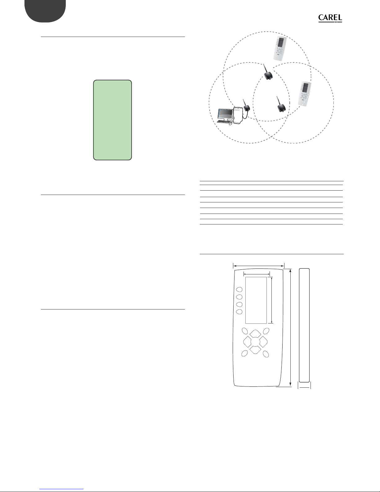
54
ENG
“Wireless probes” +0300030EN - rel. 1.0 - 16.07.2010
12.19 Start screen
When rst starting the device (inserting the batteries), the ZigBee handheld
wireless signal level meter shows the following screens in rapid succession:
• Completely black screen
• Bootloader activation screen
• Start-up animation (grid)
• Screen showing component check procedure and version number
Z-HANDHELD
ZB-Connect
Ver 08.01
Rtc 08.01
waiting..
MAC Addr
0x000D6F00
000528D1
Fig. 12.s
12.20 ZigBee handheld signal meter
shutdown
The handheld wireless signal level meter automatically goes into low power
mode after four minutes of inactivity to extend battery life.
Low power mode can be activated manually by pressing the “O ” button.
In low power mode, pressing any button returns the device to the previous
status.
Note: during the Ping Test, the O button only switches the device to low
power mode for a few seconds.
Note: If the handheld wireless signal level meter is not used for an extended
period (a few weeks) the batteries should be removed.
Battery Life
The estimated battery life is 26 hours of continuous operation of the device.
(power consumption 12J/minute, battery power 19000J, --> 19000/12 = 1580
min = 26.3 hours)
12.21 Notes on operation
The ZigBee handheld wireless signal level meter has been designed for use
when installing a new network of devices.
It identi es the number of Routers and Access Points that are accessible from
the position where the ping test is performed.
The ping test also provides information on the strength of the wireless signal
on the Routers and Access Points in the vicinity, highlighting whether the
connections are good or have a low signal.
The installation guidelines require each Router to be within radio range of at
least two other Routers. The same applies to the sensors; indeed, each sensor
should be connected with a good signal to at least two di erent Router
devices (or Access Points).
Where installation restrictions limit the optimum positioning of the Router and
sensors, the handheld wireless signal level meter can help identify the best
position for the additional Routers that must be installed in order to cover the
areas not reached by the wireless signal.
Access
point
Router
Router
Only one Router visible.
Device installation
not recommended
Two Routers visible.
Suitable position for
installing devices
Fig. 12.t
12.22 ZigBee handheld signal meter
electrical speci cations
POWER SUPPLY: 3 x 1.5V batteries, “AAA” size
RADIO CHARACTERISTICS: 2405 MHz - 2480 MHz
Rated transmission power 0 dBm
Compliant with standard IEEE 802.15.4
EmberZNet stack 3.3.x
INDEX OF PROTECTION: IP40
Code WS01L01M00 rTM SE handheld
Tab. 12.a
12.23 Physical dimensions
72,5
33
167,5
63
28
Fig. 12.u
Rules for disposing of the battery
Do not dispose of the product as municipal waste; it must be disposed of
through specialist waste disposal centres.
The product contains a battery that must be removed and separated from the
rest of the product.
Improper use or incorrect disposal of the product may negative e ects on
human health and on the environment.
The public or private waste collection systems de ned by local legislation
must be used for disposal.
In the event of illegal disposal of electrical and electronic waste, the penalties
are speci ed by local waste disposal legislation.

55
ENG
“Wireless probes” +0300030EN - rel. 1.0 - 16.07.2010
13. ROUTERSNIFFER
13.1 Router-Sni er
The sni er for ZigBee networks is a hardware device connected to the
USB port of a personal computer running a special program (Z-Con g,
downloadable from KSA) that analyses Carel proprietary ZigBee networks
and identi es which devices are able to communicate with one another,
measuring the quality of the wireless signal. Z-Con g in fact displays a graph of
wireless connection quality between the various Router nodes in the network,
displaying which sensors these receive the wireless signal from.
13.2 Technical speci cations:
Power supply: from USB port on the PC
Radio characteristics 2405 MHz - 2480 MHz
Modulation DSSS
Rated transmission power 0 dBm
Standard IEEE 802.15.4 compliant
EmberZNet stack 3.4.1
Stack Pro le 0
Pro le Proprietary ID
Encryption key Proprietary
Index of protection IP55
Code WS01M02M20
rTM SE Router-Sni er (Modbus® network configurator)
rTM SE Router-Sni er (Modbus® Network Con gurator)
Tab. 13.a
13.3 Layout
1
3
2
4
Tab. 13.b
1. Dipswitches,
2. LEDs;
3. Button;
4. Reset button
The button and dipswitches have no functions.
13.4 LED meanings
Router-Sni er unbound: all the LEDs ash together
Router-Sni er associated: only LED L2 ashes
On power-up, LEDs L1, L2, L3 on the Router-Sni er come on for around three
seconds then ash quickly for around another three seconds.
Physical dimensions
94
102
40
108
196
50
13
4
70
T1
L1
L2L3
DIP:
1 2 3 4
ON
T2
Cable lenght =
180mm
Tab. 13.c
Note: All the measurements are in mm.

56
ENG
“Wireless probes” +0300030EN - rel. 1.0 - 16.07.2010
14. ZCONFIG PROGRAM
System requirements
Z-Con g runs on a Personal Computer with the Microsoft Windows 98, 2000,
XP or XP SP2 operating system.
The program’s limited use of memory resources (hard disk-RAM) means it can
be installed and run on any recent PC.
Installation of the program requires installation of the DotNetFramework
version 2.0
Starting the program
When starting Z-Con g, the following screen is displayed:
Fig. 14.a
Main program windows
The program is divided into three main windows, selected using the buttons
at the top left of the program window
Fig. 14.b
System Settings:
Window containing the settings for the serial communication port, network
settings and graphics settings under the “Graphics Network” window.
Data Table:
This window shows the summary table of past and current wireless
communication between the Router-Sni er and the devices in the network
this is connected to.
Graphics Network:
Window showing a graph of connection levels between the devices in the
network.

57
ENG
“Wireless probes” +0300030EN - rel. 1.0 - 16.07.2010
“System Settings” window
This window features several frames:
Opens the serial port for communication with the Router-Sni er.
The port corresponding to the Router-Sni er device must be selected.
if there are several ports and it’s not clear which one the Router-Sni er is
connected to, unplug the device from the Personal Computer; then select the
Refresh button, reconnect the Router-Sni er and then select Refresh again.
The newly connected Router-Sni er will be displayed in the list and will be
easy to identify.
Fig. 14.c
Network Parameters
The network parameters consist of the Transmission channel (16 possible
values, from 11 to 26), the network PanID (network address) and the extended
PanID.
The network parameters must be identical to the network being monitored.
To identify the parameters of the desired network, check the data in the
installation le or on the supervisor.
When opening the serial connection (see the serial connection box), selecting
the “Read” button in the “Network Parameters” box reads the network
parameters for the Router-Sni er connected to Z-Con g.
If the network parameters are not available (new Router-Sni er or unbound
from the network) the default channel is 0x0B (CH11), the default PanID is
0xFFFF and the default extended PanID is null.
Fig. 14.d
Set the desired network parameters (channel and PanID), selecting “Write” runs
the command and connects the Router-Sni er to the desired network.
Only set the channel and PanID; the extended PanID must not be written, as
it’s read by the network.
Fig. 14.e
If the channel and PanID are set incorrectly and do not correspond to any
network in the vicinity of the Router-Sni er, the extended PanID is not
detected and remains null.
Fig. 14.f
The transmission power of the Router-Sni er can be set (using the
corresponding tag); to enable the value, once again select “Write”. Changing
the power has no major signi cance; indeed it’s recommended to leave the
maximum value (-1 dB).
Selecting “Reset” resets the Router-Sni er.
Selecting “Disassociate” unbinds the Router-Sni er from the current network
and consequently initialises the network parameters.
Note: sif the network binding or unbinding operations are successful, an OK
message is shown in the info eld.
Important: after having set the network parameters (selecting “Write”), in
order to properly initialise the program tables, close and open Z-Con g
again.
Graphics Colour
This box is used to set the appearance of the connecting lines between the
nodes in the “Graphics Network” window.
The thickness and colour of the lines can be set based on the band the
connection belongs to.
The thicknesses of the lines range from 1 (thin line) to 5 (thick line).
The colours of the lines can be selected from a standard colour palette.
Fig. 14.g

58
ENG
“Wireless probes” +0300030EN - rel. 1.0 - 16.07.2010
“Data Table” window
The “Data Table” window shows a table of the devices in the network.
Initially this table only shows the “Router Sni er ” device, simply called the “Sni er”.
Selecting “Start Discovery” activates discovery of the nodes in the network.
The process continues inde nitely until selecting “Stop Discovery”.
The node currently being queried is highlighted in the table.
Fig. 14.h
Backgrounds:
All ZigBee Routers send a wireless message at regular intervals (around
every 16 seconds).
This message is called “Neighbour Exchange”, it’s essentially a presence
noti cation message.
All Routers within radio range receive the messages and use them to internally
create a table called the “Neighbours Table”.
This table keeps track of all the Routers that a certain Router can see in the
immediate vicinity, together with the quality of the wireless signal.
The table is then used to de ne the routing of the wireless messages, and
consequently is fundamental in managing wireless tra c.
During the “Discovery” process, Z-Con g extrac ts the data from the Neighbour
Tables of all the Routers and Access Points in the network.
The “Discovery” processes start by extracting the Neighbour Table of the
Router-Sni er.
Each Router listed in the Router-Sni er Neighbour Table creates a new row in
the “Data Table”.
Each Router in the table is then queried for its Neighbour Table data.
This process continues until all the Routers in the network have been queried.
At the end the process starts again cyclically.
Meaning of the columns:
ID: progressive number
MAC ADDRESS: MAC ADDRESS of the node, this represents the unique address
of the device (8 bytes). This address is resident in the device from when it is
manufactures, and cannot be overwritten or deleted for the entire life of the device.
The address is represented in hexadecimal notation.
SHORT: Device network address. (This address may change during the life of
the device). The address is used for routing the wireless messages from and
to any other node of the network. The address is represented in hexadecimal
notation.
Type: Type of device (Sni er, Access Point, Router, Sensor)
N_Neighbours: Number of Routers that the device can see in radio range.
Neighbours: Network addresses of nearby devices. These addresses are
represented in hexadecimal notation. The data are used to create the graphic
links in the “Graphics Network” window.
GHOST: This column indicates whether the node is not working and
consequently has been excluded. “No” indicates that the device is working
correctly.
Meaning of the parameters:
Command rate [mS]:
Interval between receiving a response and sending the subsequent query
(min 100mS).
Timeout Time [mS]:
Interval to wait for a response, after which a further attempt is performed.
Command Retry:
Number of consecutive transmission attempts without a response, after
which the node is declared as being a Ghost; from that moment on the node
marked as being a Ghost is no longer queried.
Meaning of the buttons:
Refresh Table:
Refreshes the table of nodes
Start Discovery:
Starts the network discovery process, querying the “Neighbour Table” on
the Router-Sni er and then on all the Routers in the network. The network
discovery process continues inde nitely, until the program is closed or “Stop
Discovery” is selected.
Stop Discovery:
Ends the network discovery process.
Apply:
Applies the changes made to the operating parameters
Clear Ghost:
Deletes all the “Ghost” labels detected during the network discovery process.
Clear Table
Deletes the entire table
Print Table
Menu of print functions

59
ENG
“Wireless probes” +0300030EN - rel. 1.0 - 16.07.2010
Notes on operation:
The information summarised in the “Data Table” is the only data that Z-Con g
can extract from the network nodes. All “application layer” information, such
as logical number, operating parameters or other data cannot be extracted
directly by Z-Con g.
The network Discovery process involves numerous wireless messages
being sent between the Router-Sni er and all the nodes in the network.
This generates signi cant wireless tra c that may interfere with the
normal messages being sent over the network.
Consequently, the Discovery process should not be left running inde nitely
but rather only for the time needed to analyse the network.
When rst running the Discovery process or after resetting the Router-Sni er,
some of the MAC addresses relating to Routers discovered in the network may
be null (0000000000000000);
To resolve this problem, wait until all the Routers have been discovered,
stop the process, wait a few seconds, select “Clear Table” and then start the
Discovery process again.
Before rst running the network Discovery process, and when the layout
of the network is modi ed (adding or moving a Router), for more precise
information all the Router nodes in the network should be reset.
“Graphics Network” window
This window represents the data from the previous table in graphic form.
The information helps provide a good idea of the physical structure of the
network.
Fig. 14.i
Key to the graphic symbols
Graphic element representing the Router-Sni er:the network
address (SHORT) is in black,the MAC address is in red (last eight
gures only)All these numbers are in hexadecimal format.
Graphic element representing a Router:the network address
(SHORT) is in black,the MAC address is in red (last six gures
only)All these numbers are in hexadecimal format.Important: If
SHORT=0000 the node is the coordinator (Gateway).
Graphic element representing an End-Device:the network
address (SHORT) is in black,the MAC address is in red (last six
gures only)All these numbers are in hexadecimal format.
Tab. 14.c
Links between Routers
The connecting lines between the Router nodes indicate the quality of the
respective wireless connections (LQI).
The thickness and colour of the lines are set in the “System Settings” window.
In the centre of the link line is a green dot that divides the line into two equal
segments.
The two segments of the link line represent the two mutual quality levels; the
segment connected to the node represents the quality with which the node
receives the messages from the other node.
Often the links are asymmetrical, meaning the link line has two di erent
colours (and/or thicknesses).
This occurs if one of the two nodes sees the other with a stronger or weaker
signal.
There may be various reasons for this, for example if one of the two nodes
features power ampli ers or an antenna with better gain.
Fig. 14.j
When selecting an element in the network, the bottom left corner displays
the SHORT data, with reference to the device’s “Data Table” and MAC address.
Links between Routers and Sensors
For sensors the connecting line does not provide information on the quality
of the wireless connection, but rather simply indicates which Router is the
device’s “parent”.
Meaning of the buttons:
Print Graphics:
Menu of print functions
New Region:
Button used to create a rectangle in the graphics window with customisable
name and size.
Remove Region:
Button used to delete a rectangle in the graphics window.
Start Discovery:
Same function as the same-name button in the “Data Table” window.
Stop Discovery:
Same function as the same-name button in the “Data Table” window.
Identi cation of nodes in the network
Nodes can be identi ed using their MAC address printed on the device label.
This is in fact the only unique value amongst the data available in the Z-Con g
program.
Alternatively, the device can only be identi ed indirectly (for example,
switching a Router o and then seeing which of the nodes in table is marked
as a GHOST after some time).
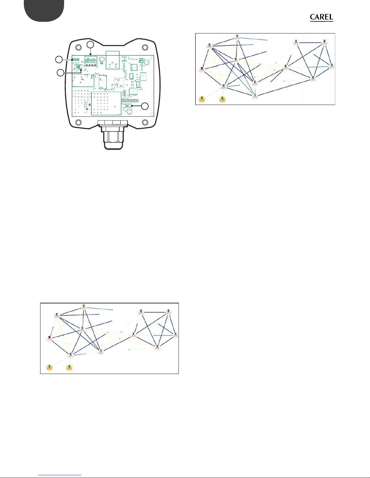
60
ENG
“Wireless probes” +0300030EN - rel. 1.0 - 16.07.2010
Device layout:
1
3
2
4
Fig. 14.k
The button and dipswitches on the Router-Sni er have no function..
LED meanings:
Router-Sni er unbound: all the LEDs ash together
Router-Sni er associated: only the centre LED ashes
On power-up, the LEDs on the Router-Sni er come on for around three
seconds then ash quickly for around another three seconds.
Purpose of Z-Con g
Z-Con g is essentially used to analyse the reciprocal positions of the Routers
in a certain ZigBee network.
It can be used to identify any critical points in the network.
Installation example:
The following gure represents a network made up of 10 Routers, the RouterSni er and two Sensors.
As can be seen, the network is divided into two subnetworks.
The two subnetworks are connected by just one good quality link (the blue
line that joins node 2560 to node 0730).
All the other links are poor quality (they’re in fact illustrated by thin yellow
lines).
This situation represents a network with possible critical areas.
Indeed, if there are obstacles in the link between node 2560 and node 0730,
the two networks may be temporarily isolated from one another.
Fig. 14.l
Situations of this type should be corrected and, where possible, further
Routers added in order to increase the number of connections between any
subnetworks.
An alternative to installing additional Routers is to move the existing ones to
better positions.
The following gure represents the same network in which an additional
Router has been installed in a strategic position.
As can be seen, the two subnetworks are connected by a further good quality
link (the blue line that joins the new node 3258 to node 0680.
Fig. 14.m
Identi cation of network parameters for ModBus networks
Modbus network parameters can be read by querying the network Access
Point.
The network channel is available by reading InputRegister[IR_03] on the
Gateway.
The network PanID is available by reading InputRegister[IR_04] on the
Gateway.
The network extended PanID is available by reading InputStatus[17],[18],[19],[20]
on the Gateway.
Important:
Before running network Discovery using Z-Con g, all the Routers in the
Modbus network should be reset, then wait around one minute.
This may can done simply by sending the special reset command to all the
Routers.
After having completed this operation, the Gateway also needs to be reset
using the special command. This operation aligns the wireless routes and
provides an updated situation of the system (it updates the links between the
Access Point, Routers and sensors).
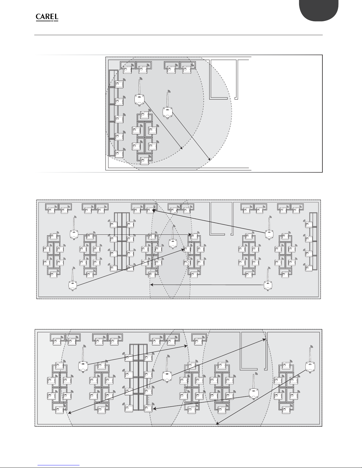
61
ENG
“Wireless probes” +0300030EN - rel. 1.0 - 16.07.2010
14.5 Layout examples
Installation examples:
- Application example involving 15 Sensors with one Access Point and Router-Bridge
Fig. 14.n
- Application example involving 30 Sensors with one Access Point and 2 Router-Bridges
Fig. 14.o
- Application example involving 30 Sensors with one Access Point and 2 Router-Bridges
Fig. 14.p

62
ENG
“Wireless probes” +0300030EN - rel. 1.0 - 16.07.2010
- Application example involving 45 Sensors with one Access Point and 3 Router-Bridges
Fig. 14.q

63
ENG
“Wireless probes” +0300030EN - rel. 1.0 - 16.07.2010
15. DIPSWITCHID CROSSREFERENCE TABLE FOR SENSORS
15.1 Dipswitch-ID cross-reference table for sensors
Dipswitch
12345678
16 00001000
17 10001000
18 01001000
19 11001000
20 00101000
21 10101000
22 01101000
23 11101000
24 00011000
25 10011000
26 01011000
27 11011000
28 00111000
29 10111000
30 01111000
31 11111000
32 00000100
33 10000100
34 01000100
35 11000100
36 00100100
37 10100100
38 01100100
39 11100100
40 00010100
41 10010100
42 01010100
43 11010100
44 00110100
45 10110100
46 01110100
47 11110100
48 00001100
49 10001100
50 01001100
51 11001100
52 00101100
53 10101100
54 01101100
55 11101100
56 00011100
57 10011100
58 01011100
59 11011100
60 00111100
Dipswitch
12345678
61 10111100
62 01111100
63 11111100
64 00000010
65 10000010
66 01000010
67 11000010
68 00100010
69 10100010
70 01100010
71 11100010
72 00010010
73 10010010
74 01010010
75 11010010
76 00110010
77 10110010
78 01110010
79 11110010
80 00001010
81 10001010
82 01001010
83 11001010
84 00101010
85 10101010
86 01101010
87 11101010
88 00011010
89 10011010
90 01011010
91 11011010
92 00111010
93 10111010
94 01111010
95 11111010
96 00000110
97 10000110
98 01000110
99 11000110
100 00100110
101 10100110
102 01100110
103 11100110
104 00010110
105 10010110
Dipswitch
12345678
106 01010110
107 11010110
108 00110110
109 10110110
110 01110110
111 11110110
112 00001110
113 10001110
114 01001110
115 11001110
116 00101110
117 10101110
118 01101110
119 11101110
120 00011110
121 10011110
122 01011110
123 11011110
124 00111110
125 10111110
126 01111110
Tab. 15.a

64
ENG
“Wireless probes” +0300030EN - rel. 1.0 - 16.07.2010
Installation data System data
Customer Channel
Address PANID
Project Extended PANID 0, 1, 2, 3
Date
Network password
(set from handheld)
Cabinet name Serial ID MAC address (Hex) Type of device
Access Point
bound
NTC probe 1 NTC probe 2 DI 1 DI 2

65
ENG
“Wireless probes” +0300030EN - rel. 1.0 - 16.07.2010


CAREL INDUSTRIES HeadQuarters
Via dell’Industria, 11 - 35020 Brugine - Padova (Italy)
Tel. (+39) 049.9716611 - Fax (+39) 049.9716600
e-mail: carel@carel.com - www.carel.com
Agenzia / Agency:
EN
“Wireless sensors” +0300030IT - rel. 1.0 - 16.07.2010
“Sonde Wireless” +0300030EN - rel. 1.0 - 16.07.2010
 Loading...