

Page 1
High Efficiency Solutions
NO POWER
& SIGNAL
CABLES
TOGETHER
READ CAREFULLY IN THE TEXT!
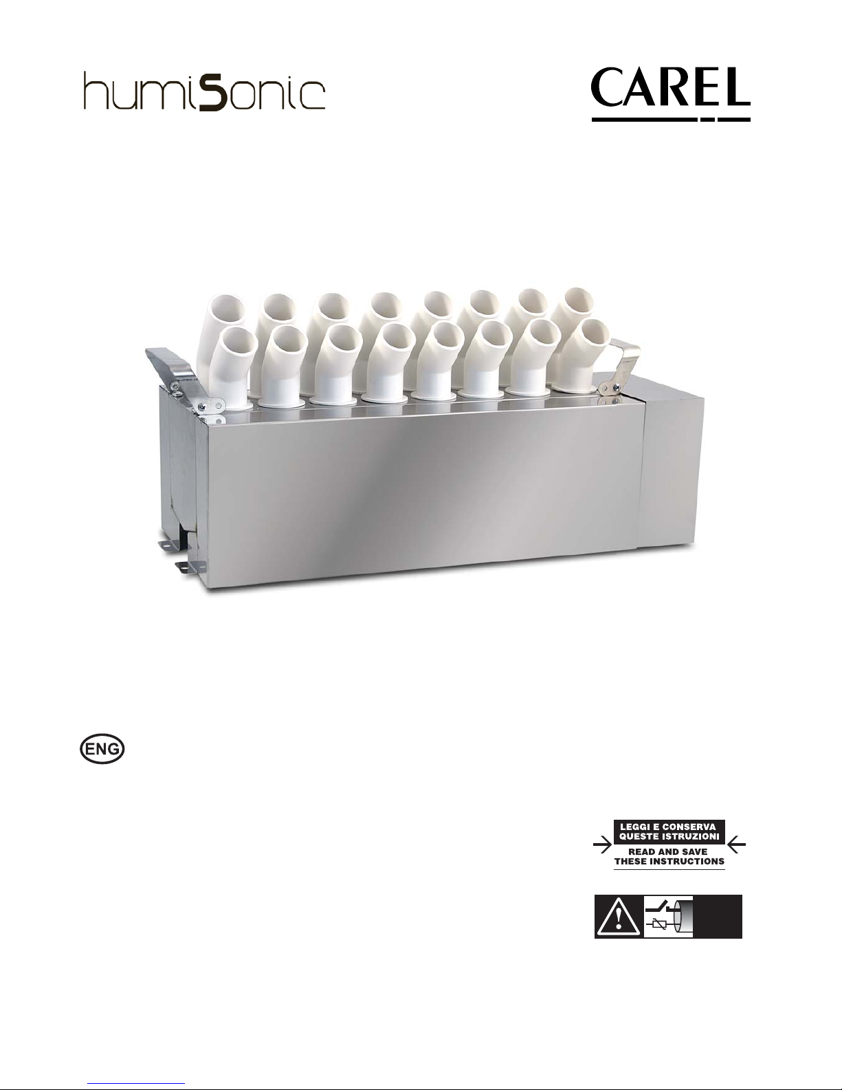
User manual
Ultrasonic humidiers
ventilation - duct version
Page 2

Page 3
3
ENG
“humiSonic ventilation” +0300063EN - rel. 1.0 - 16.02.2016
AVVERTENZE
Gli umidi catori CAREL sono prodotti avanzati, il cui funzionamento è speci cato nella documentazione tecnica
fornita col prodotto o scaricabile, anche anteriormente all’acquisto, dal sito internet www.carel.com. Ogni
prodotto CAREL, in relazione al suo avanzato livello tecnologico, necessita di una fase di quali ca/con gurazione/
programmazione a nché possa funzionare al meglio per l’applicazione speci ca. La mancanza di tale fase di
studio, come indicata nel manuale, può generare malfunzionamenti nei prodotti nali di cui CAREL non potrà
essere ritenuta responsabile. Il cliente (costruttore, progettista o installatore dell’equipaggiamento nale) si
assume ogni responsabilità e rischio in relazione alla con gurazione del prodotto per il raggiungimento dei
risultati previsti in relazione all’installazione e/o equipaggiamento nale speci co. CAREL in questo caso, previo
accordi speci ci, può intervenire come consulente per la buona riuscita della installazione/start-up macchina/
utilizzo, ma in nessun caso può essere ritenuta responsabile per il buon funzionamento dell’umidi catore ed
impianto nale qualora non siano state seguite le avvertenze o raccomandazioni descritte in questo manuale,
o in altra documentazione tecnica del prodotto. In particolare, senza esclusione dell’obbligo di osservare le
anzidette avvertenze o raccomandazioni, per un uso corretto del prodotto si raccomanda di prestare attenzione
alle seguenti avvertenze:
• PERICOLO SCOSSE ELETTRICHE: L’umidi catore contiene componenti sotto tensione elettrica. Togliere
l’alimentazione di rete prima di accedere a parti interne, in caso di manutenzione e durante l’installazione.
• PERICOLO PERDITE D’ACQUA: L’umidi catore carica/scarica automaticamente e costantemente quantità
d’acqua. Malfunzionamenti nei collegamenti o nell’umidi catore possono causare perdite.
Attenzione
Attenzione:
• Condizioni ambientali e tensione di alimentazione devono essere conformi ai valori speci cati nelle
etichette ‘dati di targa’ del prodotto.
• Installazione, utilizzo e manutenzione devono essere eseguite da personale quali cato, consapevole delle
precauzioni necessarie e in grado di e ettuare correttamente le operazioni richieste.
• Per la produzione di acqua nebulizzata si deve utilizzare esclusivamente acqua con caratteristiche indicate
nel presente manuale.
• Tutte le operazioni sul prodotto devo essere eseguite secondo le istruzioni contenute nel presente manuale
e nelle etichette applicate al prodotto. Usi e modi che non autorizzati dal produttore sono da considerarsi
impropri. CAREL non si assume alcuna responsabilità per tali utilizzi non autorizzati.
• Non tentare di aprire l’umidi catore in modi diversi da quelli indicati nel manuale.
• Attenersi alle normative vigenti nel luogo in cui si installa l’umidi catore.
• Tenere l’umidi catore fuori dalla portata di bambini e animali.
• Non installare e utilizzare il prodotto nelle vicinanze di oggetti che possono danneggiarsi a contatto con
l’acqua (o condensa d’acqua). CAREL declina ogni responsabilità per danni conseguiti o diretti a seguito di
perdite d’acqua dell’umidi catore.
• Non utilizzare prodotti chimici corrosivi, solventi o detergenti aggressivi per pulire le parti Interne ed esterne
dell’umidi catore, salvo non vi siano indicazioni speci che nei manuali d’uso.
• Non fare cadere, battere o scuotere l’umidi catore, poiché le parti interne e di rivestimento potrebbero
subire danni irreparabili.
CAREL adotta una politica di continuo sviluppo. Pertanto si riserva il diritto di e ettuare modi che e
miglioramenti a qualsiasi prodotto descritto nel presente documento senza preavviso. I dati tecnici presenti
nel manuale possono subire modi che senza obbligo di preavviso. La responsabilità di CAREL in relazione
al proprio prodotto è regolata dalle condizioni generali di contratto CAREL pubblicate nel sito www.carel.
com e/o da speci ci accordi con i clienti; in particolare, nella misura consentita dalla normativa applicabile,
in nessun caso CAREL, i suoi dipendenti o le sue liali/a liate saranno responsabili di eventuali mancati
guadagni o vendite, perdite di dati e di informazioni, costi di merci o servizi sostitutivi, danni a cose o persone,
interruzioni di attività, o eventuali danni diretti, indiretti, incidentali, patrimoniali, di copertura, punitivi, speciali
o consequenziali in qualunque modo causati, siano essi contrattuali, extra contrattuali o dovuti a negligenza o
altra responsabilità derivanti dall’ utilizzo del prodotto o dalla sua installazione, anche se CAREL o le sue liali/
a liate siano state avvisate della possibilità di danni.
SMALTIMENTO
L’umidi catore è composto da parti di metallo e parti di plastica. In riferimento alla Direttiva 2002/96/CE del Parlamento
Europeo e del Consiglio del 27 gennaio 2003 e alle relative normative nazionali di attuazione, informiamo che:
1. sussiste l’obbligo di non smaltire i RAEE come ri uti urbani e di e ettuare, per detti ri uti, una raccolta separata;
2. per lo smaltimento vanno utilizzati i sistemi di raccolta pubblici o privati previsti dalla leggi locali. È inoltre
possibile riconsegnare al distributore l’apparecchiatura a ne vita in caso di acquisto di una nuova;
3. questa apparecchiatura può contenere sostanze pericolose: un uso improprio o uno smaltimento non corretto
potrebbe avere e etti negativi sulla salute umana e sull’ambiente;
4. il simbolo (contenitore di spazzatura su ruote barrato) riportato sul prodotto o sulla confezione e sul foglio
istruzioni indica che l’apparecchiatura è stata immessa sul mercato dopo il 13 Agosto 2005 e che deve
essere oggetto di raccolta separata;
5. in caso di smaltimento abusivo dei ri uti elettrici ed elettronici sono previste sanzioni stabilite dalle vigenti
normative locali in materia di smaltimento.
Garanzia sui materiali: 2 anni (dalla data di produzione, escluse le parti di consumo).
Omologazioni: la qualità e la sicurezza dei prodotti CAREL sono garantite dal sistema di progettazione e
produzione certi cato ISO 9001, nonché dal marchio
.
WARNINGS
CAREL humidi ers are advanced products, whose operation is speci ed in the technical documentation
supplied with the product or can be downloaded, even prior to purchase, from the website www.carel.
com. Each CAREL product, in relation to its advanced level of technology, requires setup/con guration/
programming/commissioning to be able to operate in the best possible way for the speci c application. The
failure to complete such operations, which are required/indicated in the user manual, may cause the nal
product to malfunction; CAREL accepts no liability in such cases.
The customer (manufacturer, developer or installer of the nal equipment) accepts all liability and risk
relating to the con guration of the product in order to reach the expected results in relation to the speci c
nal installation and/or equipment. CAREL may, based on speci c agreements, act as a consultant for the
installation/commissioning/use of the unit, however in no case does it accept liability for the correct operation
of the humidi er and the nal installation if the warnings or suggestions provided in this manual or in other
product technical documents are not heeded. In addition to observing the above warnings and suggestions,
the following warnings must be heeded for the correct use of the product:
•
DANGER OF ELECTRIC SHOCK : The humidi er contains live electrical components. Disconnect the
mains power supply before accessing inside parts or during maintenance and installation.
•
DANGER OF WATER LEAKS:
The humidi er automatically and constantly lls/drains certain quantities
of water. Malfunctions in the connections or in the humidi er may cause leaks.
Important
Important:
•
Environmental and power supply conditions must conform to the values speci ed on the product rating labels.
•
Only quali ed personnel who are aware of the necessary precautions and able to perform the required
operations correctly may install, operate or carry out technical service on the product.
•
Only water with the characteristics indicated in this manual must be used for atomized water production.
•
All operations on the product must be carried out according to the instructions provided in this manual and
on the labels applied to the product. Any uses or modi cations that are not authorised by the manufacturer
are considered improper. CAREL declines all liability for any such unauthorised use.
•
Do not attempt to open the humidi er in ways other than those speci ed in the manual.
•
Observe the standards in force in the place where the humidi er is installed.
•
Keep the humidi er out of the reach of children and animals.
•
Do not install and use the product near objects that may be damaged when in contact with water (or
condensate). CAREL declines all liability for direct or indirect damage following water leaks from the
humidi er.
•
Do not use corrosive chemicals, solvents or aggressive detergents to clean the inside and outside parts of
the humidi er, unless speci cally indicated in the user manual.
•
Do not drop, hit or shake the humidi er, as the inside parts and the linings may be irreparably damaged.
CAREL adopts a policy of continual development. Consequently, CAREL reserves the right to make changes and
improvements to any product described in this document without prior warning. The technical speci cations
shown in the manual may be changed without prior warning.The liability of CAREL in relation to its products is
speci ed in the CAREL general contract conditions, available on the website www.carel.com and/or by speci c
agreements with customers; speci cally, to the extent where allowed by applicable legislation, in no case will
CAREL, its employees or subsidiaries be liable for any lost earnings or sales, losses of data and information,
costs of replacement goods or services, damage to things or people, downtime or any direct, indirect,
incidental, actual, punitive, exemplary, special or consequential damage of any kind whatsoever, whether
contractual, extra-contractual or due to negligence, or any other liabilities deriving from the installation, use or
impossibility to use the product, even if CAREL or its subsidiaries are warned of the possibility of such damage.
DISPOSAL
The humidi er is made up of metal parts and plastic par ts. In reference to European Union directive 2002/96/
EC issued on 27 January 2003 and the related national legislation, please note that:
1.
WEEE cannot be disposed of as municipal waste and such waste must be collected and disposed of separately;
2.
the public or private waste collection systems de ned by local legislation must be used. In addition, the
equipment can be returned to the distributor at the end of its working life when buying new equipment;
3.
the equipment may contain hazardous substances: the improper use or incorrect disposal of such may have
negative e ects on human health and on the environment;
4.
the symbol (crossed-out wheeled bin) shown on the product or on the packaging and on the instruction sheet
indicates that the equipment has been introduced onto the market after 13 August 2005 and that it must
be disposed of separately;
5.
in the event of illegal disposal of electrical and electronic waste, the penalties are speci ed by local waste
disposal legislation.
Warranty on materials: 2 years (from the date of production, excluding consumables).
Approval: the quality and safety of CAREL products are guaranteed by the ISO 9001 certi ed design and
production system, as well as by the
mark.
Page 4

Page 5

5
ENG
“humiSonic ventilation” +0300063EN - rel. 1.0 - 16.02.2016
Content
1. INTRODUCTION AND ASSEMBLY 7
1.1 humiSonic (UU0*D) .................................................................................................7
1.2 Part numbers ...............................................................................................................7
1.3 Dimensions and weights ......................................................................................7
1.4 Opening the packaging .......................................................................................7
1.5 Material supplied .......................................................................................................7
1.6 Preparing for assembly ..........................................................................................7
1.7 Assembly ........................................................................................................................8
1.8 Identifi cation label ....................................................................................................8
1.9 Functional diagram ..................................................................................................8
1.10 Operating principle ..................................................................................................9
1.11 Accessories ....................................................................................................................9
1.12 Structure .........................................................................................................................9
2. WATER CONNECTIONS 10
2.1 Warnings ......................................................................................................................10
2.2 Water connections (parts not included) ..................................................10
2.3 Positioning ..................................................................................................................10
2.4 Water connections ................................................................................................10
2.5 Feedwater ...................................................................................................................11
2.6 Drain water .................................................................................................................11
3. ELEC TRICAL CONNECTIONS 12
3.1 Humidifi er electrical connections ................................................................12
3.2 Functional wiring diagram ..............................................................................13
3.3 “Slave” electrical panel ......................................................................................... 14
3.4 “Slave” panel wiring diagram ...........................................................................15
3.5 “Master” electrical panel .....................................................................................16
3.6 “Master” panel wiring diagram .......................................................................17
3.7 Electrical connections to the “Slave” panel ............................................. 18
3.8 Connection cable sizing ....................................................................................18
3.9 Electrical connect. to the “Master” panel .................................................19
3.10 Control types.............................................................................................................19
4. STARTING AND USER INTERFACE “SLAVE” PA NEL 20
4.1 Starting .........................................................................................................................20
4.2 Shutdown / Standby ............................................................................................20
4.3 Autotest ........................................................................................................................20
4.4 Signal lights on the “Slave” panel .................................................................. 20
4.5 Disabling ......................................................................................................................20
4.6 Reset tank hour counter ...................................................................................20
4.7 Automatic washing ...............................................................................................20
4.8 Washing due to inactivity .................................................................................20
5. USER INTERFACE “MASTER” PAN EL 21
5.1 Graphic terminal .....................................................................................................21
5.2 Keypad .......................................................................................................................... 21
5.3 Display ...........................................................................................................................21
5.4 Programming mode .............................................................................................22
5.5 Setting/displaying the user parameters ..................................................22
5.6 Setting the Service parameters .....................................................................22
5.7 Quick access menus .............................................................................................23
6. COMMISSIONING “MASTER” PANEL 24
6.1 Starting .........................................................................................................................24
6.2 Scheduler ....................................................................................................................24
6.3 Regulation type .......................................................................................................24
6.4 Shutdown / Standby ............................................................................................24
6.5 Autotest ........................................................................................................................24
6.6 Reset tank hour counter ...................................................................................24
6.7 Automatic washing ...............................................................................................24
6.8 Manual procedures ...............................................................................................24
6.9 Probe calibration ....................................................................................................25
6.10 Access management ...........................................................................................25
6.11 Settings .........................................................................................................................25
6.12 Network settings ....................................................................................................25
7. FUNCTIONS “MASTER” PANEL 26
7.1 On/Off ...........................................................................................................................26
7.2 Set point.......................................................................................................................26
7.3 Regulation (control) ..............................................................................................26
7.4 Probe alarms ..............................................................................................................27
7.5 Flow-rate modulation ..........................................................................................27
7.6 Washing........................................................................................................................28
7.7 Timings .........................................................................................................................28
8. PAR A METERS TABLE “MASTER” ELECTR. PA N EL 30
9. ALARMS 33
9.1 Types of alarms ........................................................................................................ 33
9.2 Troubleshooting .....................................................................................................34
10. MAINTENANCE AND SPARE PARTS 35
10.1 Electrical components ........................................................................................35
10.2 Mechanical components ..................................................................................35
10.3 System information...............................................................................................36
10.4 Maintenance .............................................................................................................36
10.5 Maintenance operations ...................................................................................36
10.6 Maintenance intervals .........................................................................................36
10.7 Replacing the components .............................................................................36
10.8 Cleaning the tank ...................................................................................................37
11. GENERAL FEATURES AND MODELS 38
11.1 Ultrasonic humidifi er models and electrical specifi cations ..... 38
11.2 Cable cross-section ............................................................................................... 38
11.3 Technical specifi cations ......................................................................................38
11.4 Fuse table ....................................................................................................................39
12. MULTIUNITS INSTALLATION 39
12.1 Connection master-slaves (until 4 humisonics) ..................................39
12.2 Connection multi-master (until 4 masters) ............................................42
13. DUCT INSTALLATION 44
Page 6

6
ENG
“humiSonic ventilation” +0300063EN - rel. 1.0 - 16.02.2016
Page 7
7
ENG
“humiSonic ventilation” +0300063EN - rel. 1.0 - 16.02.2016
1. INTRODUCTION AND ASSEMBLY
1.1 humiSonic (UU0*D)
Range of ultrasonic adiabatic humidifi ers for direct humidifi cation in
ducts or air handling units. humiSonic is particularly suitable for many
applications in which optimisation of room humidity is an essential
factor for personal comfort and the quality of goods. The humidifi ers are
controlled by an external electrical panel. Depending on the required
functions, this can be the “Slave” (ON/OFF, status signal, remote ON/OFF)
or “Master” model (user interface and programming).
1.2 Part numbers
humisonic P/N Description
UU(XY)DD0000 without auxiliary card, without humidity probe
Tab. 1.a
(XY) = 02 2.4 kg/h, 05 4.8 kg/h, 07 7.2 kg/h, 09 9.6 kg/h,
14 14.4 kg/h, 18 18 kg/h;
Elect. panel P/N Description
UQ(XY)B(*)0000 “Slave” electrical panel
UQ(XY)C(*)0000 “Master” electrical panel
Tab. 1.b
(XY) = 05 up to 4.8 kg/h, 09 up to 9.6 kg/h, 18 up to 18 kg/h
(*) = D/1 = 230 / 110 V power supply
Note: for the table of humidifi er/electrical panel combination, see the
chapter “General features and models”.
1.3 Dimensions and weights
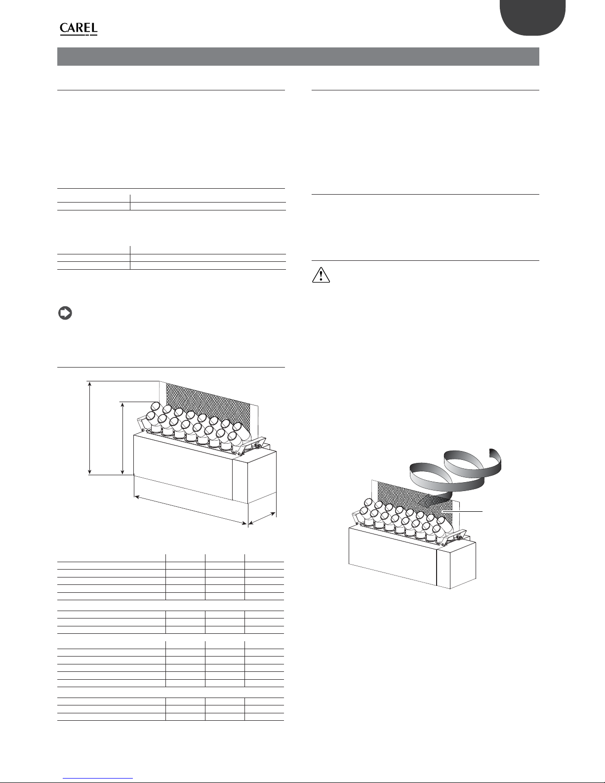
256
(10,1)
309
(12,2)
A
325
(12,8)
Fig. 1.a
Model UU02 UU05 UU07
Production (kg/h)
2,4 4,8 7,2
Height with baffl e mm(in)
325(12,8)
Height mm(in)
309 (12,2)
Depth mm (in)
256 (10,1)
Width A mm (in)
261(10,3) 386(15,2) 511(20,1)
Weight (kg (lb))
packaged
5,9(13) 7,4(16.3) 9,5(20,9)
empty
4,9(10,8) 6,4(14.1) 8(17,6)
installed*
5,7(12,6) 8,4(18,5) 10,8(23,8)
Model UU09 UU14 UU18
Production (kg/h)
9,6 14 18
Height with baffl e mm(in)
325(12,8)
Height mm(in)
309 (12,2)
Depth mm (in)
256 (10,1)
Width A mm (in)
636(25) 886(34,9) 1074(42,3)
Weight (kg (lb))
packaged
11(24,2) 14,7(32,4) 17,8(39,2)
empty
9,5(20,9) 12,7(28,0) 15,8(34,8)
installed*
13,1(28,9) 18,3(40,3) 23(50,7)
Tab. 1.c
* in normal operating conditions, fi lled with water.
1.4 Opening the packaging
□ make sure the humidifi er is intact upon delivery and immediately
notify the transporter, in writing, of any damage that may be due to
careless or improper transport;
□ move the humidifi er to the site of installation before removing from
the packaging, grasping the neck from underneath;
□ open the cardboard box, remove the protective material and remove
the humidifi er.
1.5 Material supplied
Make sure the following are included:
1. baffl e with 2 bolts;
2. user manual.
1.6 Preparing for assembly
Important: avoid installing the humidifi er in the duct in a position
where it may get wet.
• The unit is designed for assembly in compact air-conditioning units,
ventilation systems and air ducts.
• To ensure a very short free path, the atomised water needs to be
delivered as uniformly as possible along and across the duct or the
unit.
• Install the humidifi er in position where it is easily accessible/removable
for maintenance or repairs;
• Make an inspection opening on the wall of the ducting;
• To maximise absorption of atomised water in the air fl ow, for air
handling units with:
- is centrifugal, remove the defl ector (D),
- is axial or tangential, install the defl ector (D).
D
AIR
Fig. 1.b
• Place a drain tank underneath the humidifi er to collect any condensate;
this must be at least 0.6 m long and cover the free path. Install a drain
line with drain trap: the height of the drain trap must exceed the
system static pressure to ensure adequate draining of the tank.
• Air velocity in the duct must be between 1.5 and 3 m/s, so that the
atomised water is rapidly dispersed. In the event of faster air fl ows,
the cross-section of the duct must be increased so that the velocity is
within the allowed range. The length of the widened section must be
at least 0.6 m beyond the humidifi er in the direction of air fl ow, so as to
minimise condensation on the walls of the ducting or air handling unit.
Page 8
8
ENG
“humiSonic ventilation” +0300063EN - rel. 1.0 - 16.02.2016
1
2
4
5
V: 1.5 - 3 m/s
3
basic panel
complete panel
6
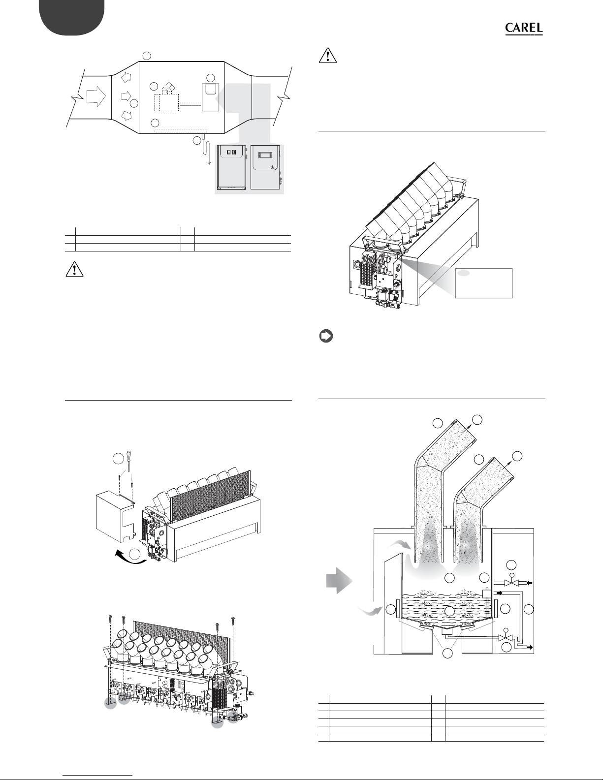
Fig. 1.c
Key
1 Stainless steel duct 4 Air fl ow
2 Humidifi er 5 Condensate collection basin
3 Control panel (external) 6 Drain trap
Important:
1. Choose the installation position so that the air fl ow disperses the
atomised water uniformly;
2. Make sure that the supporting surface is able to support the weight
of the unit.
The humidifi er can only be activated (atomised water production)
when the air handling unit fan is running. NEVER start atomised water
production without air fl ow in the duct: this may damage one or more
parts of the appliance.
1.7 Assembly
The appliance must be assembled on a horizontal support. Check correct
positioning using a spirit level.
Procedure:
1. Unscrew the screws (A) and remove the right side cover (B);
A
B
Fig. 1.d
2. Secure the humidifi er to the horizontal support using the fastening
brackets on the right and left sides;
Fig. 1.e
Important:
1. Install the humidifi er in horizontal position, using a spirit level, so
that the level sensor does not give a false reading;
2. Carefully secure the unit so that it does not move during operation.
1.8 Identifi cation label
The humidifi ers are identifi able from the packaging label and the
identifi cation label on the side.
S.N.
A0002066 Rev.2.0
Date
Code
D
a
t
e
0
4
-
N
o
v
-
2
0
1
4
S
.
N.
A
0
0
0
2
0
6
6
R
e
v
.
C
o
d
e
UU1%D%0000
04-Nov-2014
Fig. 1.f
Note: tampering with, removing or failing to reattach the identifi cation
labels or anything else that prevents certain identifi cation of the product will
make installation and maintenance operations more diffi cult.
1.9 Functional diagram
M
M
1
1
2
2
3
4
6
5
7
8
9
9
10
air
flow
Fig. 1.g
Key
1 Atomised water 7 Float level sensor
2 Diff user 8 Tank
3 Atomisation chamber 9 Driver
4 Fill valve 10 Piezoelectric transducer
5 Overfl ow pipe 11 Power supply
6 Drain valve
Page 9
9
ENG
“humiSonic ventilation” +0300063EN - rel. 1.0 - 16.02.2016
1.11 Accessories
• BMS/RS485 serial card (P/N PCOS004850): to be installed on the control
board on the ““Master”” panel, used for direct interface to an RS485
network, with a maximum baud rate of 19200. The board guarantees
opto-isolation of the controller from the RS485 serial network.
• Humidity/temperature probes for ducts, CAREL P/Ns DPD*(T/H),
DPP*(T/H). Used in ducted heating and air-conditioning systems.
Supplied together with a mounting bracket. See manual +030220660.
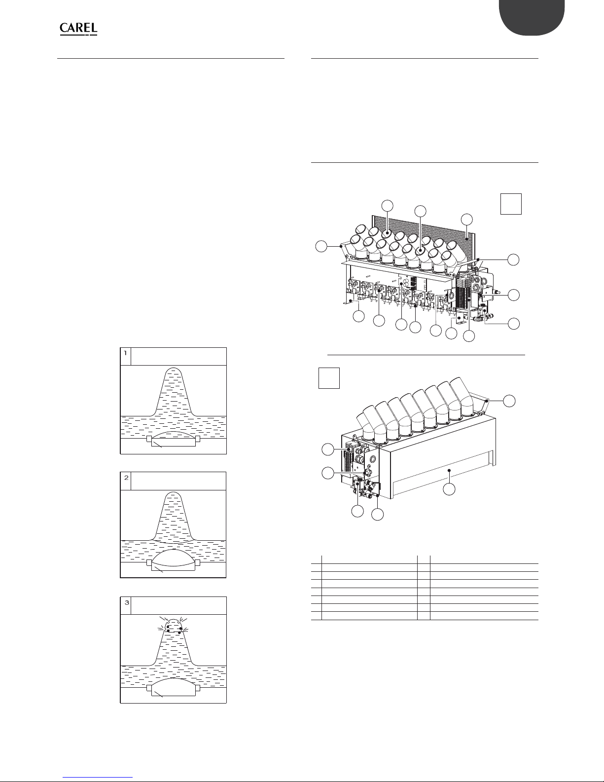
1.12 Structure
The fi gure shows the body of the humidifi er, once having removed the
side panels and the cover (see chap. “Spare parts and maintenance”).
F
2
5
12
3
6
11
4
7
10
5
7
1
1
1
8
9
6
8
13
8
R
Fig. 1.i
Key
F Front 7 Terminal block
R Rear 8 Fastening bracket
1 Lifting handles 9 Bracket with cable glands
2 Rear diff user 10 Piezoelectric transducer
3 Front diff user 11 Electronic control board
4 Baffl e 12 Driver
5 Fill valve 13 Air intake
6 Drain valve
1.10 Operating principle
The operation of humiSonic humidifi ers is based on the principle of
atomisation of demineralised water using ultrasound technology. The
humidifi er operating principle can be summarised as follows:
• water fi ll via a fi ll solenoid valve until reaching the required level,
measured by the fl oat;
• if the autotest is enabled (default), the drain solenoid valve opens and
empties the tank (function designed to clean the tank of any residues/
dirt);
• water fi lled again to the required level;
• start ultrasonic atomisation (the air fl ow in the duct carries the particles
of moisture and distributes them into the surrounding environment);
• water refi ll based on the fl oat measures that the level has fallen below
the recommended value.
Ultrasound technology uses a voltage input signal that is transformed
via an oscillating circuit into a high frequency signal (1.7 MHz). This signal
supplies a transducer, the top of which is in contact with the water, which
starts vibrating at high frequency. The surface of the transducer vibrates
at very high speed (1.7 million times a second), a speed that does not
allow the water to move, due to its inertial mass. Consequently, a column
of water is created above the transducer. During the negative amplitude
of the transducer cycle, a void is created that is not fi lled by the water (as
this cannot respond to the extremely fast movements of the transducer).
The cavity thus created leads to the production of bubbles that are
pushed to the edge of the water column during the positive amplitude
of the cycle, thus colliding. During this process, very fi ne particles of water
are atomised on the edge of the water column. The resulting intersecting
sound waves created directly underneath the surface of the water cause
very small droplets of water to separate, forming a fi ne mist of vapour
that is immediately absorbed by the fl ow of air.
Dopo l'accensione
After switching on
Trasduttore / Transducer
Ampiezza negativa
Negative amplitude
Vuoto / Vacum
Trasduttore / Transducer
Ampiezza positiva
Positive amplitude
Trasduttore / Transducer
Fig. 1.h
Page 10
10
ENG
“humiSonic ventilation” +0300063EN - rel. 1.0 - 16.02.2016
2. WATER CONNECTIONS
IMPORTANT: before proceeding with the water connections,
make sure that the humidifi er is not connected to the mains power
supply.
2.1 Warnings
1. Only use demineralised water. Install a shut-off valve for each humidifi er.
Allowable water pressure: from 1 to 6 bars;
2. The connections between the pipes/hoses in contact with demineralised
water and the humidifi er must be made from resistant material
suitable for this use (e.g. PVC or stainless steel);
3. The water lines must not be fouled by dust particles or other substances.
Carefully clean the lines before connecting to the
humidifi er;
4. All humiSonic ultrasonic humidifi ers are supplied with quick couplings
for connecting the fi ll hose (OD / ID = 8/6 mm).
2.2 Water connections (parts not included)
• Install a manual shut-off valve upstream of the installation (so as to
shut off the water supply); the valve must be suitable for use with
demineralised water.
• Install a mechanical fi lter (10 m) downstream of the manual shut-off
valve to trap any solid impurities; the fi lter must be fi tted with shut-off
devices to allow cleaning;
• Install a condensate collection basin that is at least 0.6 m longer than
the humidifi er, made from corrosion-resistant material such as plastic
or stainless steel.
Important:
1. when installation is completed, fl ush the supply hose for around 30
minutes by piping water directly into the drain, without sending it
into the humidifi er. After installing the valve, fl ush with water to
eliminate any processing residues and oil and prevent that enter the
humidifi er;
2. the drain hose must have a minimum diameter of 6 mm; it must
not have any bends that block water fl ow; the drain line must
comply with national and local standards in force and must include
a funnel to ensure interruption of continuity and a drain trap
to prevent the return of bad odours. The end of the line must have a
downwards slope to assist drainage;
3. do not block the atomised water outlet or the intake air
openings;
4. always check for water leaks. If the humidifi er is sprayed with water
during operation, short circuits may occur;
5. if there is the risk of the feedwater freezing, insulate the
water pipes.
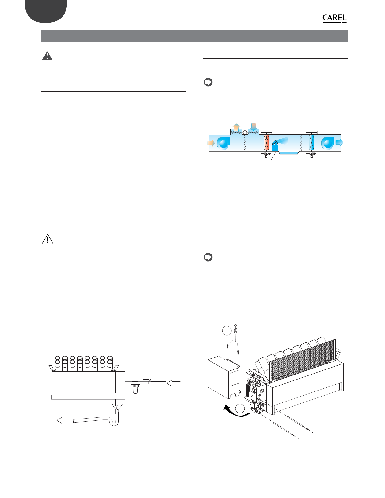
water drain
water inlet
drain pan
Fig. 2.a
2.3 Positioning
As seen in chap.1, the humidifi er must be installed in ducting where the
air velocity is between 1.5 and 3 m/s.
Note: when calculating air velocity in the duct, keep in mind that the
area occupied by the humidifi er needs to be subtracted from the crosssection of the duct.
The recommended position is downstream of the heating coil.
CD
HU
CC
G
I
PC
G
I
G
E
DP
Recommended location
Fig. 2.b
Key
GITotal air fl ow-rate introduced HU Humidifi er
CD Combined dampers DP Condensate collection tank
G
E
Outside air fl ow-rate CC Cooling coil
PC Heating coil
If assembling multiple humidifi ers, arrange them in a structure that can
support the weight of the appliances and that leaves optimum space
between the units, so as to ensure effi cient operation. Install a manual
shut-off valve for each humidifi er.
Note: any obstacles in front to the humidifi er are places where water
may condense.
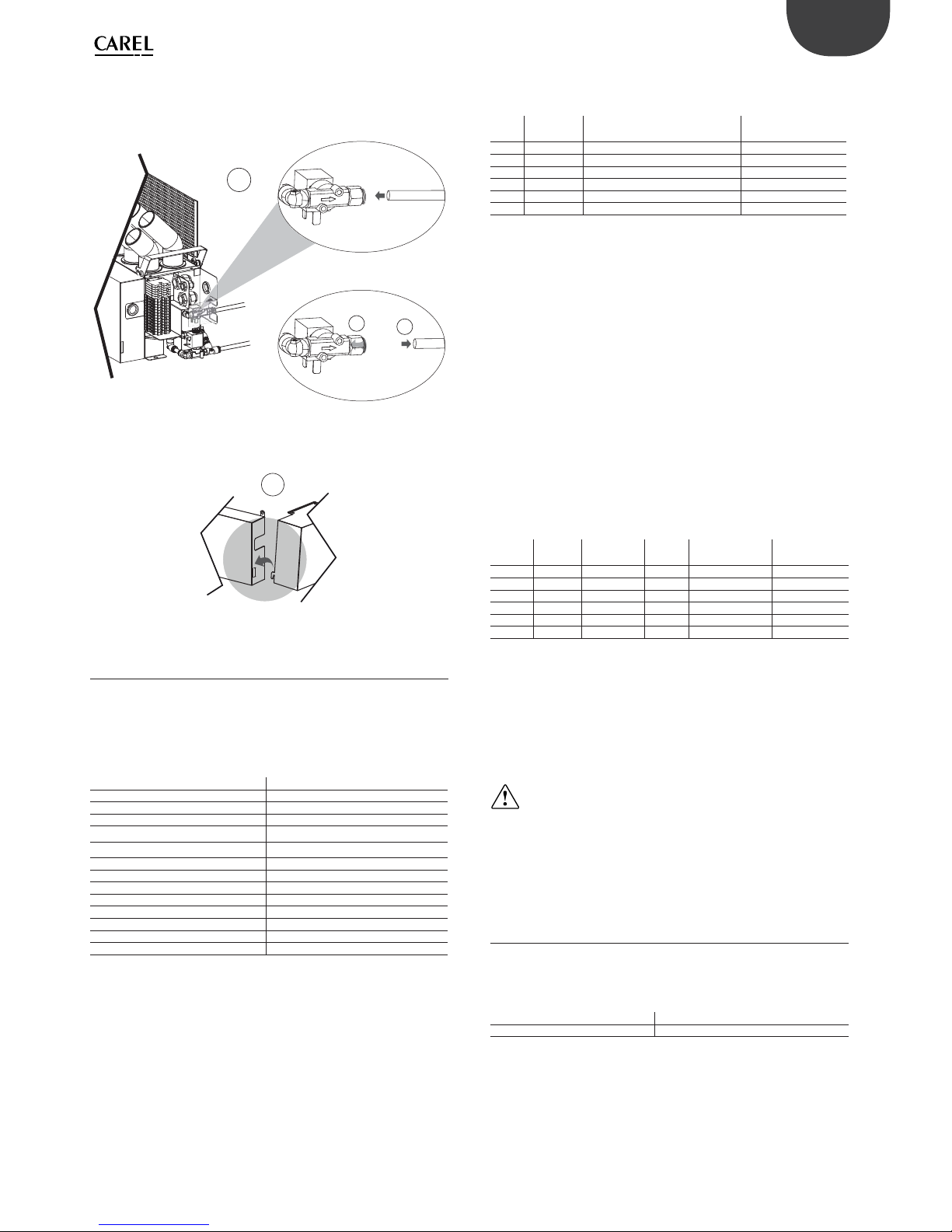
2.4 Water connections
Once the humidifi er has been fi tted, make the water connections as
follows:
1. Unscrew the screws (A) and remove the right side cover (B);
B
Carico/ Fill
Scaric
o
/ Drain
A
Fig. 2.c
Page 11
11
ENG
“humiSonic ventilation” +0300063EN - rel. 1.0 - 16.02.2016
2. Attach the pipes to the quick couplings (C) to connect the fi ll/drain
valves;
C
1
2
Insert
Extract
Fig. 2.d
3. Reposition the cover, paying attention to the point of attachment (D).
D
Fig. 2.e
2.5 Feedwater
To ensure correct operation, humiSonic requires the use of demineralised
water, with the chemical and physical characteristics specifi ed in the table.
To ensure these water quality values, a reverse-osmosis demineralisation
system is typically used.
FEEDWATER
Quick coupling OD 8 mm (0,32”)
Temperature limits °C (°F) 1…40 (33.8 to 104)
Pressure limits MPa (bar) 0,1…0,6 (1 to 6)
Specifi c conductivity at 20°C 20…80 µS/cm
Total hardness 0…25 mg/l CaCO
3
Temporary hardness 0…15 mg/l CaCO
3
Total quantity of dissolved solids (cR) Depending on specifi c conductivity
(1)
Dry residue at 180°C Depending on specifi c conductivity
(1)
Iron + manganese 0 mg/l Fe+Mn
Chlorides 0 to 10 ppm Cl
Silicon dioxide 0 to 1 mg/l SiO2
Chlorine ions 0 mg/l Cl
Calcium sulphate mg/l CaSO4
Instant fl ow-rate (l/min) 2
Tab. 2.a
(1) = in general C
R
=0,65 * σ
R,20 °C
; R
180
= 0,93 * σ
R,20 °C
To avoid excessive oversizing of the reverse osmosis system, it is
recommended to avoid sizing the system based on instant fl ow-rate.
Rather, an expansion vessel should be installed between the water
treatment system and humiSonic.
The sizing calculations need to consider discontinuous water
consumption, comprising the following stages:
• fi lling (fi ll valve open);
• production (fi ll valve closed);
• washing (fi ll valve open).
The table below suggests the minimum sizes for connection to a generic
reverse osmosis system.
Model Stora ge Total expansion vessel volume
(pre-charge 1.5 bars)
Reverse osmosis
system
UU02 2.8 l 11.2 l 5.2 l/h
UU05 3.6 l 14.4 l 8.4 l/h
UU07 4.4 l 17.6 l 11.6 l/h
UU09 5.2 l 20.8 l 14.8 l/h
UU14 6.8 l 27.2 l 20.8 l/h
UU18 8.0 l 32.0 l 26.0 l/h
Tab. 0.a
If no storage vessel is available, the reverse osmosis system must
guarantee the instant fl ow-rate of the fi ll SV, equal to 2 l/min.
Connecting humiSonic to the Carel WTS Compact
The Carel product range includes a series of reverse osmosis systems
(“WTS Compact”) designed to produce water according to the feedwater
specifi cations and optimise connection to and operation with humiSonic
(see manuals +0300017 and +0300019).
All WTS Compact systems (P/N ROC%) always come with an expansion
vessel that maintains the required pressure in the circuit downstream.
Operation of the system is managed by pressure switches in the outlet
circuit. The basic rule for connection to the humidifi er is that the water
contained in the expansion vessel must be suffi cient to satisfy initial fi lling
and, if necessary, the washing cycle, while the WTS production time must
cover humiSonic production demand and fi ll the vessel as quickly as
possible.
The table below suggests the water consumption values and connections
for all sizes of humidifi ers.
Model Prod.
(l/h)
Tank
capacity (l)
Wash (l)
(*)
WTS Additional
vessel
UU02 2.4 0.8 4.8 ROC025500N Not required
UU05 4.8 1.6 5.6 ROC025500N Not required
UU07 7.2 2.4 6.4 ROC025500N Not required
UU09 9.6 3.2 7.2 ROC025500N Not required
UU14 14.4 4.8 8.8 ROC025500N ROKC00KT VE
UU18 18 6.0 10.0 ROC025500N ROKC00KTVE
Tab. 2.b
(*) Water consumption during the washing cycle is calculated based on
the default settings (1 wash every 24 hours, lasting 2 minutes, which ends
by totalling fi lling and emptying the volume of the tank). Consumption
depends on the fi ll solenoid valve fl ow-rate, which is 2 litres/minute. The
duration and frequency of the washing cycles are parameters that can be
set by the user, and these have a signifi cant impact on the sizing of the
WTS system.
Important:
1. do not add disinfectants or anticorrosive compounds to the water, as
these are potential irritants;
2. the use of well water, industrial water or water from cooling
circuits and, in general, any potentially chemically or bacteriologically
contaminated water is prohibited.
2.6 Drain water
This is not toxic and can be drained into the sewerage system, as defi ned
by directive 91/271/EEC on urban waste-water treatment.
DRAIN WATER
Quick coupling OD 8 mm (0,32”)
Typical temperature °C (°F) 1 to 40 (33.8 to 104)
Tab. 2.c
Page 12
12
ENG
“humiSonic ventilation” +0300063EN - rel. 1.0 - 16.02.2016
3. ELECTRICAL CONNECTIONS
3.1 Humidifi er electrical connections
Important
Important:
• before proceeding with the electrical connections, ensure that the
control panel – humidifi er system is disconnected from the mains
power supply;
• make sure that the power supply voltage of the control panel
corresponds to the value indicated in the rated data.
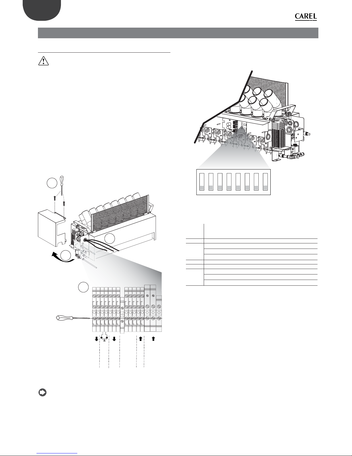
To power up the humidifi er, connect the cables running from the
electrical panel:
1. +48 Vdc/ -48 Vdc from the power supply;
2. +24 Vac/ -24 Vac from the transformer;
3. the power cable for the lights (“Slave” electrical panel only);
4. the cable for the signal lights (“Slave” electrical panel) or RS485 serial
line (“Master” electrical panel).
After having removed the screws (A), remove the side cover (B) and run
the cables through the cable glands on the case and inside the unit
(C). Then make the electrical connections (D) and reposition the cover,
repeating the same operations in reverse.
+ 48 V
- 48 V
G
G0
0TX/RX
+TX/RX
-TX/RX
+5V
WHITE
RED
ONOFF
COM
AL_A
AL_B
SHD
PE
Alarm contact (N.O.)
ON/OFF production
RED AND BLU LEDS
RS485
24 Vac Power Supply
48 Vdc Power Supply
Shield
A
B
C
D
Fig. 3.a
Note: to avoid unwanted interference, power cables should be kept
separate from probe signal cables.
DIPSWITCH CONFIGURATION
The dipswitches are located on the humidifi er control board. These must
be set before starting the humidifi er.
2
3
6475
1
8
ON
Fig. 3.b
Key
1
Communication
OFF: Carel/Modbus Serial 485
ON: Reserved
2-3 Reserved
4
Serial 485 / tLAN baud rate
OFF: 19200
ON: 9600
5-6 Reserved
7 Reserved
8
Transducer production management
OFF: --> parallel
ON: --> series
Page 13
13
LOW LEV.
GND
HIGH LEV.
F
Level flow
switch
+
-
230/ 110 Vac
L
N
+ GND
Piezoelectric
transducer
Pool
Driver
48 Vdc
Power Supply
D
G
G0
Driver
Driver
Driver
Control
board
Drain
valve
Fill
valve
3,15 A T
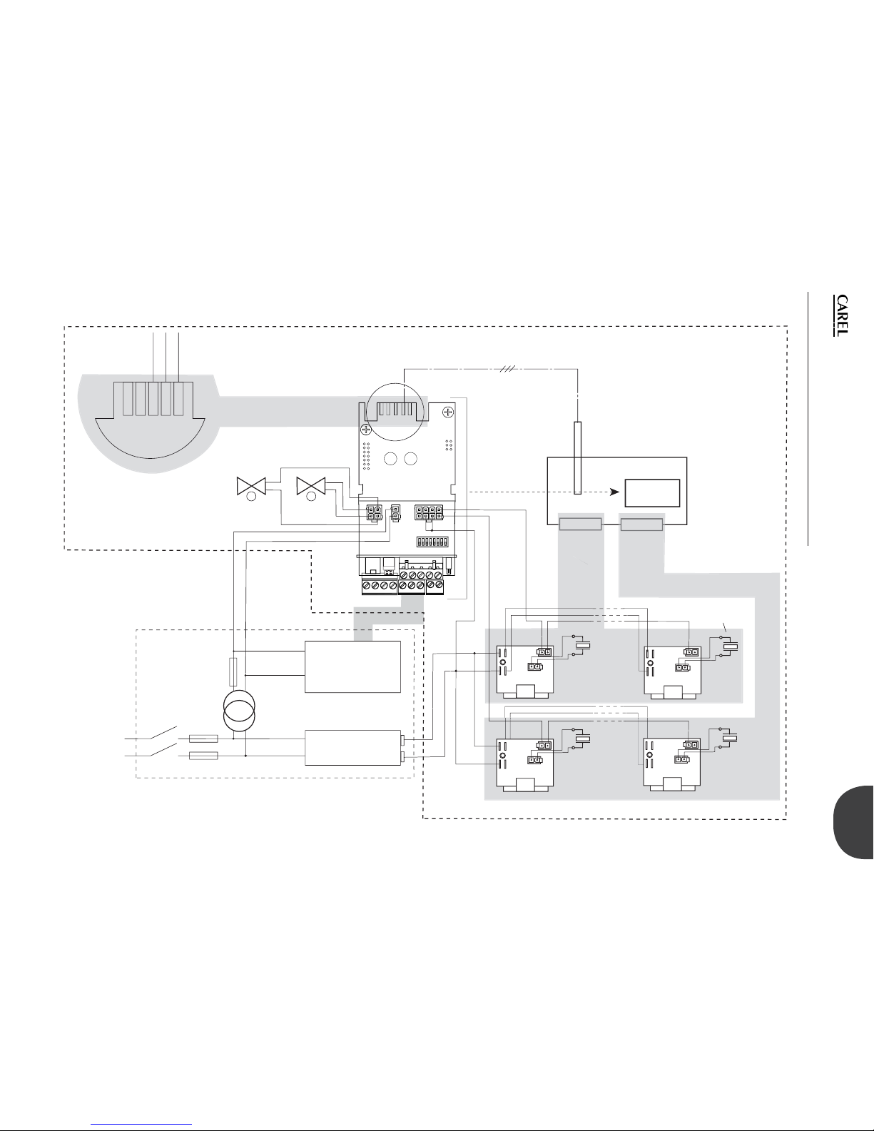
Control board (*)
(*) Only for complete panel
GND + -
ELECTRICAL PANEL
(basic / complete)
Serial connection
humiSonic
Control
board
Driver: 4 to 30
LEVEL FLOW
SWITCH
ENG
“humiSonic ventilation” +0300063EN - rel. 1.0 - 16.02.2016
3.2 Functional wiring diagram
Fig. 3.c
Page 14
14
ENG
“humiSonic ventilation” +0300063EN - rel. 1.0 - 16.02.2016
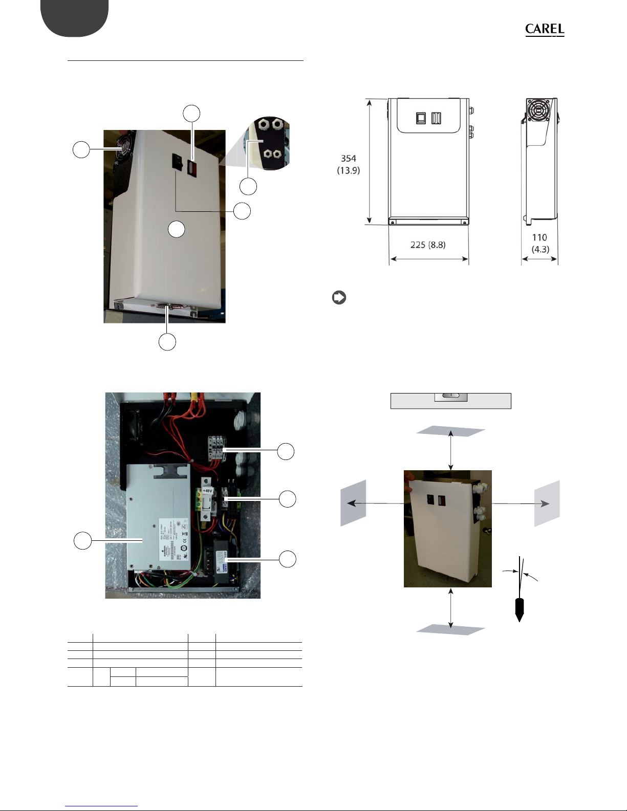
DIMENSIONS - mm (in)
Fig. 3.f
Note: for UQ18B% dimensions, refer to the quotes indicated in 3.5
section concerning “
Master” control panel.
POSITIONING
The electrical panel is designed for wall-mounting and features forced
ventilation for cooling. See the fi gure for the minimum clearances in mm
(in) that ensure suffi cient air fl ow and change inside the electrical panel.
<0,5°
≥ 500
(19.7”)
≥ 500
(19.7”)
≥ 500
(19.7”)
≥ 500
(19.7”)
Fig. 3.g
3.3 “Slave” electrical panel
STRUCTURE
OUTSIDE
1
2
3
4
5
6
Fig. 3.d
INSIDE
10
9
8
7
Fig. 3.e
Key
1 Exhaust air fan 6 Cable glands
2 Cover 7 Light terminal block
3 Air intake 8 Main terminal block
4 ON/OFF switch 9 Transformer
5
LED BLUE power 10 Power supply
RED alarm
Page 15
15
+48 V
- 48 V
G
G0
PE
L
N
5 V
BLUE
RED
R
B
PRI: WH BK RD OR
COM: 120 208 240
SEC: BL - YL 24 V 75 VA
50/ 60 Hz CLASS 2
YL BL
24 V
L
N
+ 48 V
LN
- 48 V
ON/ OFF
FA N
FA N
LED COMMANDS
FROM HUMIDIFIER
230 Vac POWER SUPPLY
24 Vac TO HUMIDIFIER
48Vdc to
HUMIDIFEIR
PE
1~
Power supply
OUT = 48 V DC
3,15 A T
“SLAVE”
ELECTRICAL PANEL
ENG
“humiSonic ventilation” +0300063EN - rel. 1.0 - 16.02.2016
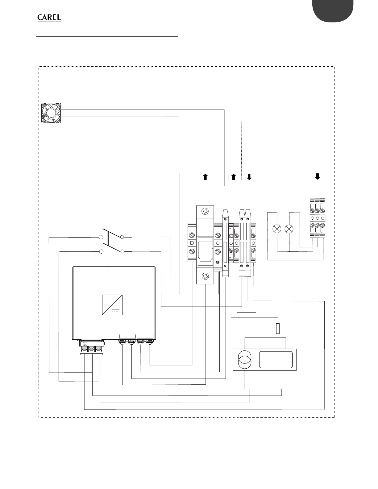
3.4 “Slave” panel wiring diagram
Fig. 3.h
Page 16
16
ENG
“humiSonic ventilation” +0300063EN - rel. 1.0 - 16.02.2016
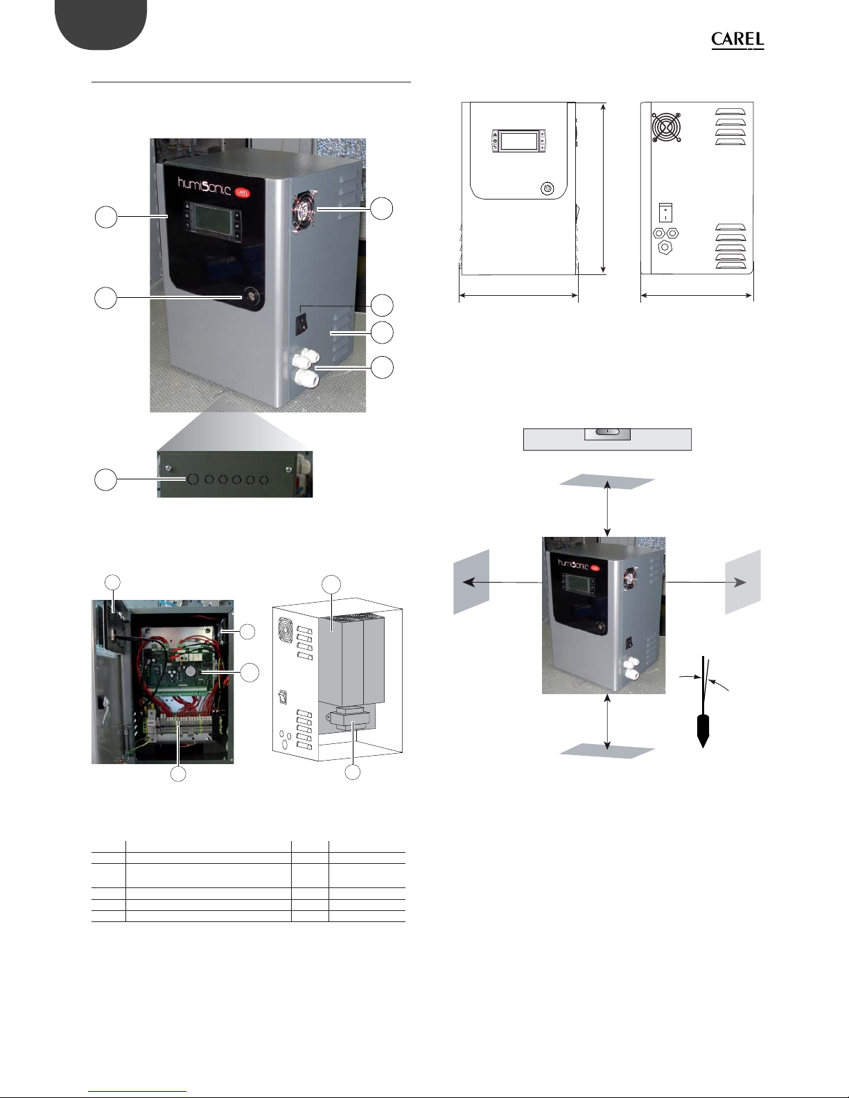
3.5 “Master” electrical panel
STRUCTURE
OUTSIDE
1
4
7
5
6
2
3
Fig. 3.i
INSIDE
8
10
7
1
9
11
Fig. 3.j
Key
1 Terminal 7 Exhaust air fan
2 Cover with lock 8 Terminal block
3
Knock-outs for additional cable
glands (installer’s responsibility)
9 Transformer
4 Cable glands 10 Control board
5 Air intake openings 11 Power supply
6 ON/OFF switch
DIMENSIONS - mm (in)
262 (10.3)
361
(14.2)
252 (9.9)
Fig. 3.k
POSITIONING
The electrical panel is designed for wall-mounting and features forced
ventilation for cooling. See the fi gure for the minimum clearances in mm
(in) that ensure suffi cient air fl ow and change inside the electrical panel.
<0,5°
≥ 500
(19.7”)
≥ 500
(19.7”)
≥ 500
(19.7”)
≥ 500
(19.7”)
Fig. 3.l
Page 17
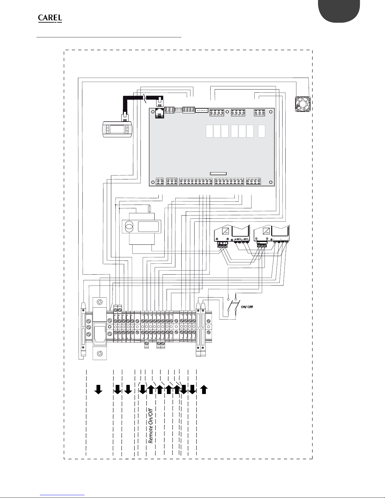
17
“MASTER”
ELECTRICAL PANEL
RX-/TX-
RX+/TX+
GND
Vout
RX-/TX-
RX+/TX+
GND
C1
NO1
NO2
NO3
C2
NO4
NO5
NO6
NO7C7NC7
G
G0
B1B2B3B4B5B6B7
GND
+Vdc
+Vdc
GND
+5 Vref
GND
Y1Y2Y3
DI1
DI2
DI3
DI4
DI5
DI6
DI7
DIC1
J2 - probe supply
J3 - analog input
J4 - digital input
J5 - analog output
J6
J7
J8
J9
J10
J11
J1 - power supply
J12 - group 1
J13 - group 1
J14 - group 2
J2 - probe supply
J3 - analog input
J4 - digital input
J5 - analog output
J6
J7
J8
J9
J10
J11
J1 - power supply
J12 - group 1
J13 - group 1
J14 - group 2
PRI: WH BK RD OR
COM: 120 208 240
SEC: BL - YL 24 V 75 VA
50/ 60 Hz CLASS 2
YL
BL
24 V
L
N
PE
+ 48 V
PGD1*
- 48 V
+ V
G
0_RS485
+_RS485
G0
-_RS485
SHD
PR%
COM
ON/ OFF
HST
COM
M_PB
L_PB
SHD
PR_A
PR_B
AL_A
AL_B
L
N
PE
+ 48 V
LN
- 48 V
FAN
POWER
SUPPLY
POWER
SUPPLY
FAN
1~ 1~
POWER
SUPPLY
48 V dc TO HUM.
24 V ac TO HUM.
Serial connection
Analogue output prod. %
230 Vac Power Supply
Alarm contact
On production
Humidostat
Main probe
Limit probe
S90CONN*:
Connection
cable
3,15 A T
ENG
“humiSonic ventilation” +0300063EN - rel. 1.0 - 16.02.2016
3.6 “Master” panel wiring diagram
Fig. 3.m
Page 18
18
ENG
“humiSonic ventilation” +0300063EN - rel. 1.0 - 16.02.2016
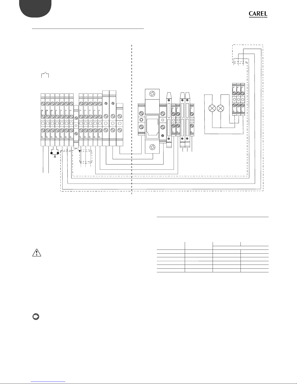
3.7 Electrical connections to the “Slave” panel
Below is the connection diagram between the terminal block on the
“Slave” electrical panel and the terminal block on the humidifi er.
+48 V
- 48 V
G
G0
PE
L
N
+5
WHITE
RED
R
B
FA N
PE
+ 48 V
- 48 V
G
G0
0TXRX
+TXRX
-TX/RX
+5V
WHITE
RED
ONOFF
COM
AL_A
AL_B
SHD
PE
Alarm
Power
Supply
L
N
PE
Serial
connection
HumiSonic terminal block
Basic panel terminal block
Fig. 3.n
HUMIDISTAT OR REMOTE CONTACT (ON/OFF action)
Production is enabled by closing the ONOFF – COM contact on the
terminal block. This can be connected to a switch, a humidistat or a
controller (voltage-free contact, max 5 Vdc open, max 7 mA closed).
RS485 SERIAL CONNECTION
CAREL/ Modbus protocol: -TXRX-, +TXRX, 0TXRX terminals.
Important
Important: for RS485 connections in household (IEC EN 55014-1)
and residential (IEC EN 61000-6-3) environments, use shielded cable (with
shield connected to PE both on the terminal and controller ends),
maximum length specifi ed by the EIA RS485 protocol, equivalent to
European standard CCITT V11, using AWG26 twisted pair cable; the input
impedance of the 485 stage is 1/8 unit-load (96 kOhm). This confi guration
allows a maximum of 256 devices to be connected, with cables in
separate conduits from the power cable.
ALARM RELAY
Terminals: AL_B, AL_A
Ready for remote signalling of one or more alarms.
Note: in industrial environments (IEC EN61000-6-2) the signal cables
leaving the unit must not exceed 10 m (33 ft) in length: remote on/off digital
input (ON/OFF - COM terminals) and shielded cable for RS485 communication.
3.8 Connection cable sizing
The table below shows the sizing of the 48 Vdc connection cable between
the humidifi er and the “Slave” or “Master” electrical panel. The minimum
cross-section depends on the length. Use cable for working voltages
≥ 300 Vac and operating temperatures ≥ 90°C.
P/N Current (A) L=5 m L=10 m
AWG (mm2)
UU02D% 3.2 14(2.5) 14(2.5)
UU05D% 6.4 14(2.5) 14(2.5)
UU07D% 9.6 14(2.5) 13(4)
UU09D% 12.8 14(2.5) 13(4)
UU14D% 19.2 10(6) 10(6)
UU18D% 24 10(6) 9(10)
Tab. 3.a
24 Vac connection: two-wire cable, type AWG 16 (1.32 mm2).
Light connection (“Slave” panel only): three-wire shielded cable, type
AWG 22 (0.33 mm2).
Page 19
19
ENG
“humiSonic ventilation” +0300063EN - rel. 1.0 - 16.02.2016
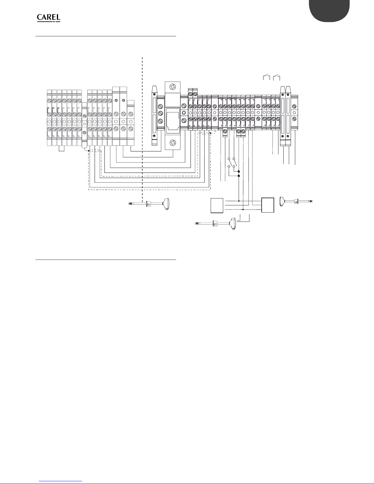
3.9 Electrical connect. to the “Master” panel
Below is the connection diagram between the terminal block on the
“Master” electrical panel and the terminal block on the humidifi er.
Depending on the type of signal, atomised water production can be
enabled and/or managed in diff erent ways.
+ 48 V
- 48 V
G
G0
0TXRX
+TXRX
+5V
WHITE
RED
ONOFF
COM
AL_A
AL_B
SHD
PE
PE
+ 48V
- 48 V
+ V
G
G0
SHD
PR%
COM
ONOFF
HST
COM
M_PB
L_PB
SHD
PR_A
PR_B
AL_A
AL_B
L
N
PE
FAN
Produ-
ction
Regulation probe
(0…1Vdc, 0…5Vdc)
M - G0
OUT H/T
(G+)
Alarm
Power
Supply
Serial connection
NTC probe (*)
M - G0
OUT H
(G+)
0TXRX
-TXRX
+TXRX
-TXRX
Do not
connect
Shield
HumiSonic terminal block
Complete panel terminal block
(*) See technical leaflet cod. +050001245 for electrical wiring
Limit probe
(0…1Vdc, 0…5Vdc)
Fig. 3.o
3.10 Control types
To enable all types of control:
1. Humidifi er terminal block: Jumper terminals COM and ONOFF;
2. Terminal block on the “Master” electrical panel: Jumper terminals
ONOFF and COM (enable)
ON/OFF CONTROL (humidistat or remote contact):
“Master” electrical panel terminal block
• Connect terminals HST and COM to a humidistat or remote contact
(voltage-free contact);
• Set Fa01: Regulation type = On/Off .
EXTERNAL PROPORTIONAL CONTROLLER (modulating action):
“Master” electrical panel terminal block
• Connect terminals COM and M_PB (main probe) to an external controller;
• Set Fa01: Ext. regulator;
• Set parameter Fa04 for the type of signal from the external controller:
Probe type = 0 to 1V, 0 to 5V.
EXTERNAL PROPORTIONAL CONTROLLER (mod. action) + limit rH%:
“Master” electrical panel terminal block
• Connect terminals COM and M_PB (main probe) to an external controller;
• Set Fa01: Ext. regulator + limit rH%;
• Set parameter Fa04 for the type of signal from the external controller:
Probe type = 0 to 1V, 0 to 5V;
• Set parameter Fa06 for the type of signal from the limit probe: Probe
type = 0 to 1V, 0 to 5V.
TEMPERATURE CONTROL
“Master” electrical panel terminal block
• Connect terminals COM, +V and M_PB (main probe) to a temperature
probe;
• Set Fa01: T probe;
• Set parameter Fa04 for the type of signal from the temperature probe:
Probe type = 0 to 1V, 0 to 5V, NTC.
TEMPERATURE CONTROL + limit rH%
“Master” electrical panel terminal block
• Connect terminals COM, +V and M_PB (main probe) to a temper. probe
and terminals COM, +V and L_PB (limit probe) to an active humidity probe;
• Set Fa01: T probe +limit rH%;
• Set parameter Fa04 for the type of signal from the temperature probe:
Probe type = 0 to 1V, 0 to 5V, NTC.
• Set parameter Fa06 for the type of signal from the limit probe: Probe
type = 0 to 1V, 0 to 5V.
HUMIDITY CONTROL
“Master” electrical panel terminal block
• Connect terminals COM, +V and M_PB (main probe) to a humidity probe;
• Set Fa01: probe rH%;
• Set parameter Fa04 for the type of signal from the humidity probe:
Probe type = 0 to 1V, 0 to 5V.
HUMIDITY CONTROL + Limit %rH
“Master” electrical panel terminal block
• Connect terminals COM, +V and M_PB (main probe) to a humidity
probe and terminals COM, +V and L_PB (limit probe) to an active
humidity probe;
• Set Fa01: probe rH% + limit rH%;
• Set parameter Fa04 for the type of signal from the humidity probe:
Probe type = 0 to 1V, 0 to 5V;
• Set parameter Fa06 for the type of signal from the limit probe: Probe
type = 0 to 1V, 0 to 5V.
FINAL CHECKS
The following conditions represent correct electrical connection:
• mains power to the humidifi er corresponds to the rated voltage;
• a mains disconnect switch has been installed so as to be able to
disconnect power to the humidifi er;
• terminals COM – ONOFF on the humidifi er terminal block are jumpered
or connected to a contact to enable operation; if the humidifi er is
controlled by an external controller, the signal earth is electrically
connected to the controller earth.
Page 20
20
ENG
“humiSonic ventilation” +0300063EN - rel. 1.0 - 16.02.2016
4. STARTING AND USER INTERFACE “SLAVE” PANEL
Before starting the humidifi er check:
• water connections: in the event of water leaks, do not start the
humidifi er before having restored the connections;
• electrical connections between the humidifi er and the control panel.
4.1 Starting
See chap. “Electrical connections”
1. The humidifi er, once powered and enabled for production (remote on-
off /humidistat), is ready for operation.
2. Operation will only stop if the enabling signal is no longer present.
4.2 Shutdown / Standby
1. To switch the humidifi er off , press the ON/OFF button.
2. The humidifi er goes into standby when:
• the remote on/off contact is open;
• the on/off contact is open and serial enabling is set to 1 (see
chapter “Humidifi er control via network“).
When the humidifi er is in standby, the tank is emptied automatically
4.3 Autotest
When the humidifi er is fi rst started (from off ), if enabled and humidity
production is required, a test cycle is run. A complete fi ll and drain cycle
is performed, during which the level sensor is monitored; if the test is
successful, regular atomised water production will start. If the test fails,
production is disabled (see the alarm table).
4.4 Signal lights on the “Slave” panel
Blue light
Steady Humidity production
Slow fl ash* Standby
Fast fl ash** Autotest or wash
* Slow fl ash: 1 s ON and 1 s OFF
** Fast fl ash: 0.2 s ON and 0.2 s OFF
The red LED means an alarm is active. See the chapter on Alarms for the
alarm table.
4.5 Disabling
The humidifi er can be disabled in three diff erent ways:
• Opening the COM-ONOFF contact (enabling signal);
• Active alarms;
• Via network.
4.6 Reset tank hour counter
The humidifi er is fi tted with an hour counter that records operation.
After a set number of hours (5,000), a signal is activated to indicate
maintenance should be performed on the tank and operation of the
piezoelectric elements checked (see the chapter on Maintenance). To
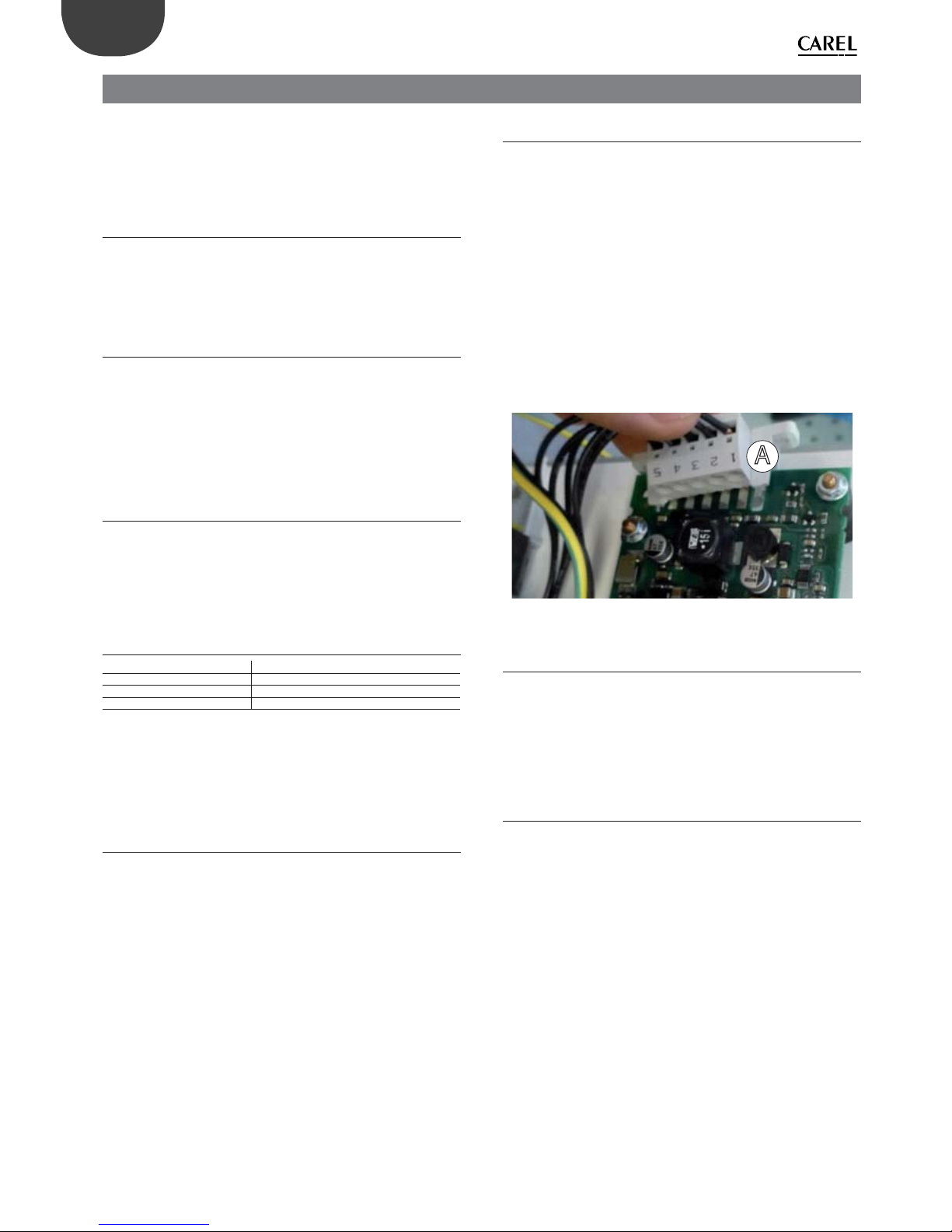
reset the hour counter at any time, proceed as follows:
• switch the humidifi er off ;
• close the water supply tap and wait for the tank to empty completely;
• remove the front panel from the humidifi er to access the control board;
• unplug the Lumberg connector on the control board;
• open the On/Off contact;
• switch the humidifi er on (with the Lumberg connector disconnected
from the control board). Both lights will fl ash;
• close the On/Off contact. The yellow LED will remain on steady;
• switch the humidifi er off ;
• plug the Lumberg connector (A) onto the board, making sure it is
inserted in the correct direction;
• switch the humidifi er on.
A
Fig. 4.a
4.7 Automatic washing
The humidifi er automatically runs a washing cycle at set intervals (default
60 minutes) during which time atomised water is produced. The washing
cycle involves a complete drain cycle, a phase in which fi ll and drain are
activated together (1 minute) to fl ush out any residues in the tank, a
complete fi ll cycle and fi nally another complete drain cycle. During this
operation, atomised water production is stopped.
4.8 Washing due to inactivity
If the humidifi er remains inactive (on but in standby) for an extended
period (24 hours) a washing cycle is performed, as described in the
previous paragraph. This cleans the tank of any residues (e.g. dust) that
may have accumulated during the period of inactivity. The washing cycle
is run after 24 hours (continuous) of no operation, i.e. the humidifi er is in
standby.
Page 21
21
ENG
“humiSonic ventilation” +0300063EN - rel. 1.0 - 16.02.2016
5. USER INTERFACE “MASTER” PANEL
5.1 Graphic terminal
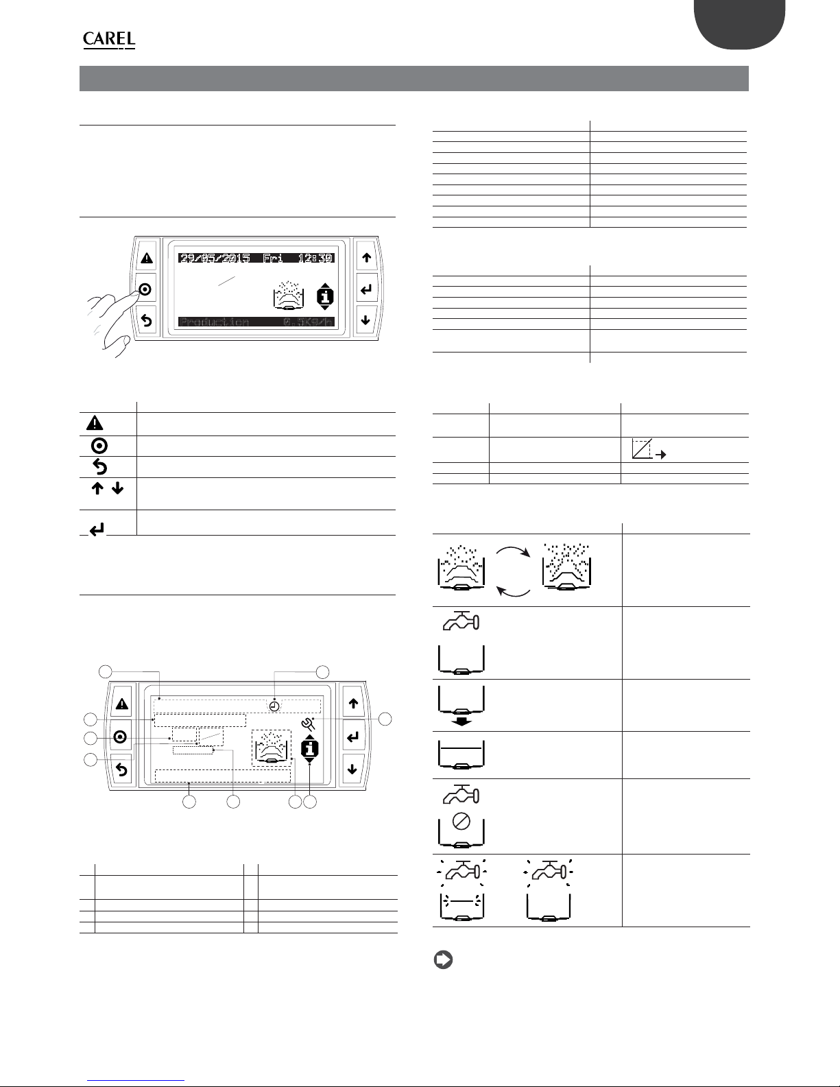
The built-in terminal on the “Master” electrical panel comprises the
display and the keypad, featuring 6 buttons, which are used to perform
all the confi guration and programming operations on humiSonic.
5.2 Keypad
0N
'RI
0/
0''
1RODUCTION,GH
Fig. 5.a
BUTTON DESCRIPTION
Alarm
• Display the list of active alarms
• Reset alarms with manual reset
Prg
Access to the main menu
Esc
Return to the previous screen
/
Up / Down
• Scroll between screens
• Increase / decrease the value
Enter
• Switch from display mode to setting mode
• Confi rm the value and move to the next parameter
Tab. 5.a
5.3 Display
During normal operation, the display shows, as well as the current
date and time, the type of control selected, the reading of the control
probe and limit probe (if featured), and the quantity of atomised water
produced.
1
29/05/2015 Fri 12:30
7 8
On
ON
OFF
3
9
Unit Offline
2
Production 0.5Kg/h
5
99.2rH%
6
4
10
Fig. 5.b
Key
1 Current date/time 6 Limit humidity probe reading
2
Cause of unit shutdown/Unit
status
7 Unit status icon/active actuators
3 Request 8 Quick access button menu icon
4 Control type selected 9 Maintenance required
5 Unit status 10 Time bands enabled
CAUSE OF UNIT SHUTDOWN
Message Description
Off by Key Off from keypad
Unit Offl ine Unit offl ine
Remote On/Off Remote On/Off
No request No request
Unit disabled Unit disabled
Alarms Alarms
Manual mode Manual mode
Off from BMS Off from BMS
Off from Sched. Off from Sched.
Tab. 5.h
UNIT STATUS
Message Description
Production …Kg/h/(lb/h) Instant production in kg/h (lb/h)
Drain Drain
Init Initialisation
Fill Filling
Autotest Autotest
Waiting (.. min) Waiting (.. min) to restart
Disabled Disabled
Tab. 5.b
Request Meaning Control type
On/-- On= request
--- = no request
On/Off
0 to 100 % Request percentage
%
Ext. regulator
rH%: Control probe reading in rH% rH% probe
°C Control probe reading in °C T probe
Tab. 5.c
Unit status/ active actuators Meaning
Production
Fill
Drain
Water present
Stop transducer control
Malfunction
Tab. 5.d
Note: the control type is selectable in user menu F, under screen Fa01:
Regulation. See the parameter table.
Page 22
22
ENG
“humiSonic ventilation” +0300063EN - rel. 1.0 - 16.02.2016
5.4 Programming mode
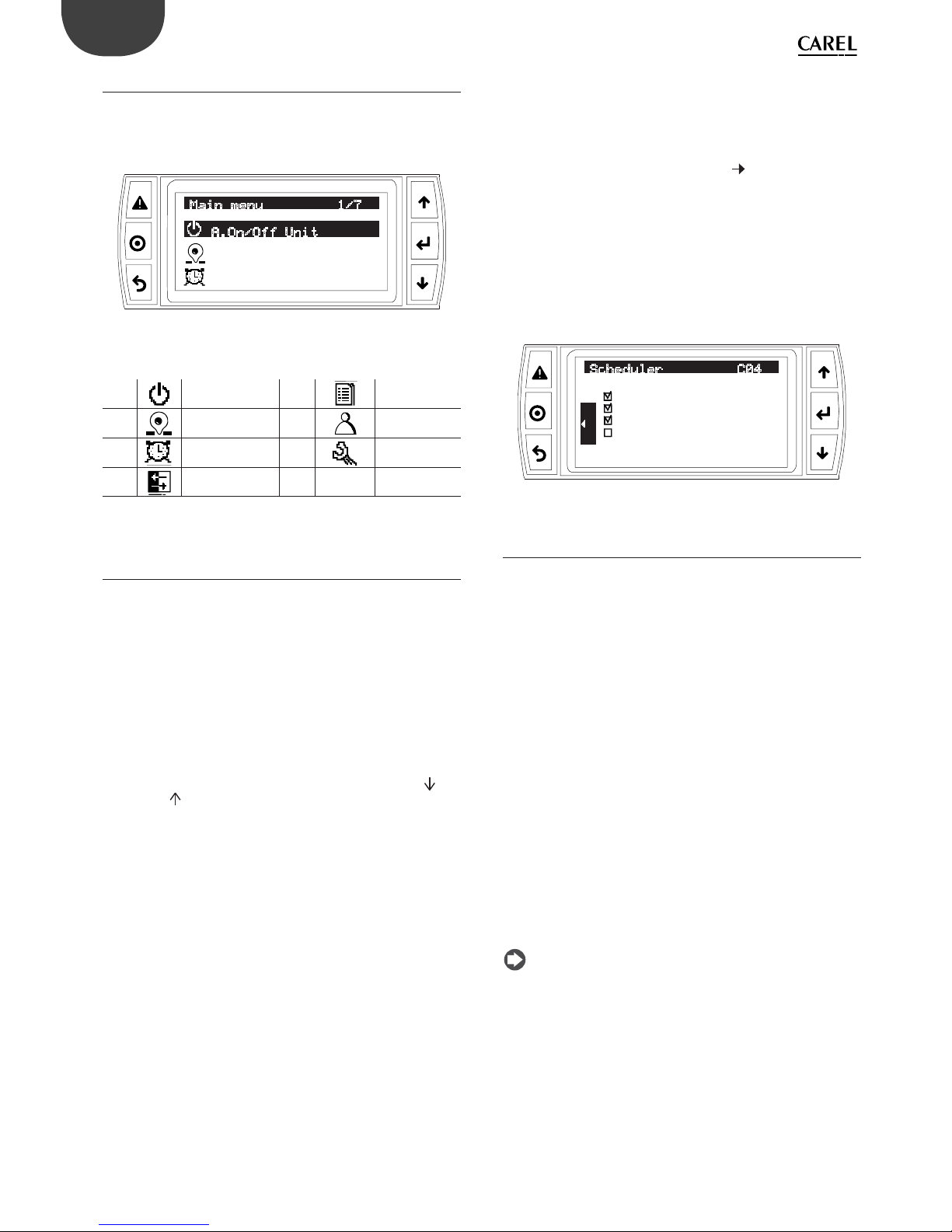
The parameters can be modifi ed using the front keypad. Access diff ers
according to the level: User (accessible without password), Service
(password=PW1) and Manufacturer (password = PW2). Press Prg to
access the main menu.
C.Clock/Scheduler
Main menu 1/7
A.On/Off Unit
B.Setpoint
Fig. 5.c
Main menu icons
A. Unit On/Off E. Alarm log
B.
Set point F. User
C.
Clock/scheduler G. Service
D. Master/ Slave
(future uses)
Tab. 5.e
5.5 Setting/displaying the user parameters
The user parameters (A…F) are all the parameters accessible without
password, and include the following categories:
A: Unit ON/OFF: enable power-on from keypad, enable Autotest and
manual washing, set maximum production.
B: Set point: if Fa01 is set to control with probe (+ limit humidity probe),
the screen will show the humidity/temperature set point (+limit humidity
set point);
C: Clock/scheduler: set the current time and date (C01), the date for
changeover from standard time to daylight saving time and vice-versa
(C02), the daily time bands (C03) with weekly programming: up to 3
daily time bands can be set with independent set points. See example
2 described below.
D: Master-Slave network confi guration: Reserved.
E: Alarm log: the alarm log contains all the alarms, both active ( ) and
already reset (
). The display can include up to 50 alarms with progressive
numbering, time and date of activation.
F: User: select the type of control and related parameters, enable washing
and activation mode, general settings for restart times, alarm relay logic,
drain valve in standby. See the chapter on “Functions”.
EXAMPLE 1: Setting the current time/date.
1. press Esc one or more times to move to the standard display;
2. press Prg: the display shows the main menu;
3. press UP/DOWN to move to category C. Clock/scheduler;
4. press Enter to display the fi rst screen: C01;
5. press Enter to modify the current time using UP/DOWN; confi rm by
pressing Enter and set the month and year;
6. confi rm by pressing Enter and set the hour/minutes;
7. at the end of the settings, press Esc twice to exit the parameter setting
procedure.
EXAMPLE 2: Setting the time bands and copying from one day to
another.
• press Esc one or more times to move to the standard display;
• press Prg: the display shows the main menu;
• press UP/DOWN to move to category C. Clock/scheduler and Enter
again until reaching screen C03;
• press Enter and enable the time bands (No Yes); then go to screen
C04;
• in screen C04:
a. press Enter and UP/DOWN to show the check sign for time band 1;
b. press Enter and UP/DOWN to select the day of the week. Confi rm by
pressing Enter. Press UP/Down to uncheck the box. Press Enter to set
the band start hours and minutes and the status: OFF, ON, ON+SET
(ON+SET if control with probe selected). If ON, the set point selected
in screen B is shown, if ON+Set, set the desired set point;
c. once the time bands have been set for the day in question, press PRG
to copy the settings from one day to another.
Day:MON
Scheduler C04
07:00 ON 50.0%
09:00 ON+SET 70.0%
10:00 OFF --.-%
--:-- --- --.-%
--:-- --- --.-%
--:-- --- --.-%
&
2
3
<
Fig. 5.d
5.6 Setting the Service parameters
The Service parameters (letter G) concern:
a: change language;
b: information on: application, BIOS and BOOT version; fl ash memory and
RAM on the control board;
c: hour counter: operating hours in production and total unit operating
hours; maintenance interval setting.
To access the screens from d) on, the service password is needed PW1(0077).
d: BMS confi guration: set BMS communication protocol (CAREL, Modbus),
communication speed, network address, enable control serial.
e:
• Timings (Gea): set fi ll/drain times, refi lling, production, delay for
water level or no communication alarms between control panel and
humidifi er. See the chapter “Functions”;
• Delete alarm log (Geb), counter and restore default parameters;
• Access management (Gec): interval of new Service password entry
when browsing, enable quick menu (On/Off and set point), enter User
password (PW0), change Service password (PW1).
f: Manual management: manual activation of fi ll/drain valves, group 1/2
(mist 1/2) of piezoelectric transducers, alarm relay, ambient and limit
probes.
Procedure: the setting/display procedure is similar to the one for the user
parameters, however password PW1 must be entered to access category
G parameters.
Note:
• if no button is pressed, after around 5 min the display automatically returns
to standard mode;
• the service password PW1 can be changed on screen Gec04 (and the main
password on screen Gec03);
• once entered, the password remains active for a certain time, after which it
needs to be entered again.
Page 23
23
ENG
“humiSonic ventilation” +0300063EN - rel. 1.0 - 16.02.2016
5.7 Quick access menus
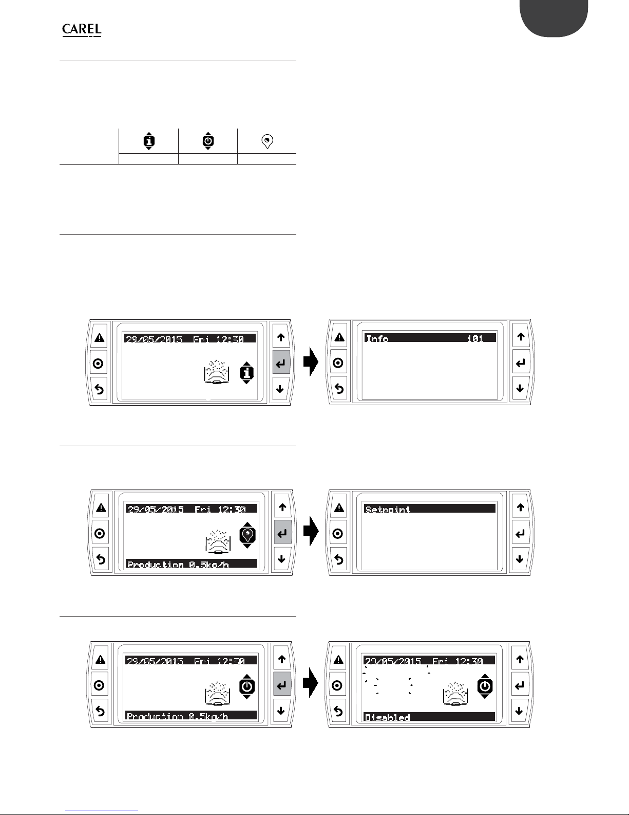
The quick access menus can be used to rapidly access the unit information
and settings.
Procedure:
1. Press Esc one or more times to return to the standard display;
2. Press UP/DOWN to show the required quick access menu icon;
ICON
Info On/Off Set point*
Tab. 5.f
(*) Only shown if control with probe is selected for Fa01.
3. Press Enter to enter the menu, UP/DOWN to scroll, ESC to exit.
5.6.1 Info
Read-only screens that display the main unit information:
• Humidifi er size;
• Waiting time until the next wash;
• Operating hours with atomised water production;
• Total unit operating hours;
• Float level sensor status: low, working (normal operation), high;
• Dipswitch status on the control board
50.0rH%
Production 0.5Kg/h
90.0rH%
29/05/2015 Fri 12:30
Humidifier size:
0.5Kg/h
Next Wash : 22h
Info i01
Fig. 5.e
5.6.2 Set point
Only shown if control with probe has been selected (Fa01).
On this screen, the control set point for humidity / temperature probe
and limit humidity probe set point can be set.
50.0rH%
90.0rH%
29/05/2015 Fri 12:30
Setpoint
Production 0.5kg/h
Setpoint : 50.0rH%
Limit : 90.0rH%
Fig. 5.f
5.6.3 On/O
Unit On/Off from the keypad.
50.0rH%
90.0rH%
29/05/2015 Fri 12:30
rH%
90.0rH%
29/05/2015 Fri 12:30
Production 0.5kg/h
Disabled
Off by key
--.-
Fig. 5.g
Page 24
24
ENG
“humiSonic ventilation” +0300063EN - rel. 1.0 - 16.02.2016
6. COMMISSIONING “MASTER” PANEL
Important
Important:
Before starting the humidifi er check:
• water connections: in the event of water leaks, do not start the
humidifi er before having restored the connections;
• electrical connections between the humidifi er and the control panel.
The following series of parameters needs to be set when commissioning
the unit.
6.1 Starting
See chap. “Electrical connections”
1. The humidifi er, once powered and enabled for production (remote on-
off /humidistat), is ready for operation.
2. Operation will only stop if the enabling signal is no longer present.
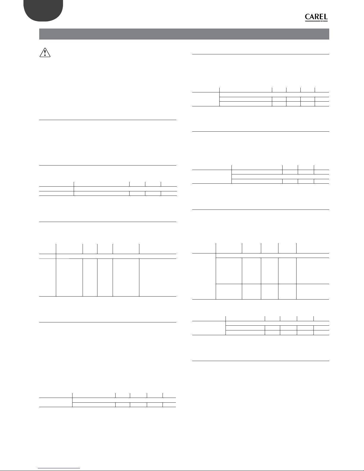
6.2 Scheduler
Programming is weekly, with the possibility to enter up to 3 daily time
bands, each with a diff erent set point. See chap. “User interface”
Screen index Display description Def Min Max
C03 Scheduler
Enable scheduler ? No No Yes
Tab. 6.a
6.3 Regulation type
Select whether control is based on a humidistat, external controller,
humidity/temperature probe and a limit humidity probe. See chapter
“Functions”.
Screen
index
Display
description
Def Min Max UOM
Fa01 Regulation
Regulation
type
On/Off On/Off T probe+limit
rH%
On/Off ¦ Ext.
regulator ¦ Ext.
regulator+limit
rH% ¦ rH% probe ¦
rH% probe+Limit
rH% ¦ T probe ¦ T
probe+limit rH%
Tab. 6.b
6.4 Shutdown / Standby
1. To shutdown the humidifi er, switch the unit Off from the keypad (see
chap. “User interface);
2. The humidifi er goes into standby when:
- the remote on/off contact is open;
- the humidity/temperature probe is present and the humidity set
point has been reached;
- the on/off contact is open and serial enabling is set to 0 (see
chapter “Humidifi er control via network “).
When the humidifi er is in standby, the tank is emptied automatically, if
the valve in standby is selected as open.
Screen index Display description Def Min Max UOM
Fc03 Settings
Drain valve in stand-by Open Closed Open -
Tab. 6.c
6.5 Autotest
When the humidifi er is fi rst started (from off ), if enabled and humidity
production is required, a test cycle is run. A complete fi ll and drain cycle
is performed, during which the level sensor is monitored; if the test is
successful, regular atomised water production will start. If the test fails,
production is disabled (see the alarm table).
Screen index Display description Def Min Max UOM
A01 On/Off
Enable No No Yes Autotest Yes No Yes -
Tab. 6.d
6.6 Reset tank hour counter
The humidifi er is fi tted with an hour counter that records operation.
After a set number of hours (5,000), a signal is activated to indicate
maintenance should be performed on the tank and operation of the
piezoelectric elements checked (see the chapter on Maintenance). To
reset the hour counter at any time, go to screen Geb01.
Screen index Display description Def Min Max
Geb01 Reset Cnt/Logs
…
Reset counter No No Yes
Tab. 6.e
6.7 Automatic washing
The humidifi er, if enabled on the screen or via BMS, automatically runs a
washing cycle at set intervals, defi ned by parameter “Operating period”.
See the functions chapter for the parameters corresponding to activation
of the washing cycle. During this operation, atomised water production
is stopped.
Screen
index
Display
description
Def Min Max Value desc.
Fb01 Washings
Time
triggered
Absolute
time
Disab. Progr. Disabled ¦
Absolute time
¦ Working/
No working ¦
Scheduled
Event
triggered
Disab. Disab. From
request
Disabled ¦ From
digital input ¦
From request
Tab. 6.f
Screen index Display description Def Min Max UOM
Fb03 Work wash (Fb01= Work /Standby)
Enabled Yes No Yes Work wash period 1 1 480 min
Tab. 6.g
6.8 Manual procedures
At the end of the programming procedure, before starting the unit,
manual operation can be enabled in order to:
1. run a fi ll/drain cycle;
2. activate production by one group of transducers (mist1/ mist 2) or
both;
3. activate the alarm relay
Page 25
25
ENG
“humiSonic ventilation” +0300063EN - rel. 1.0 - 16.02.2016
Screen index Display description Def Min Max UOM
Gf01 Manual management
Manual mode No No Yes -
Gf02 Manual mode
Fill Off Off On Off ¦ On
Drain Off Off On Off ¦ On
Gf03 Manual mode
Mist 1 No No Yes No ¦ Yes
Mist 2 No No Yes No ¦ Yes
Tab. 6.h
6.9 Probe calibration
Once the control (regulation) type has been selected, the probes can
be calibrated by setting the off set. The delay for activation of the probe
alarm can also be set.
Screen index Display description Def Min Max UOM
Fa04 Regulation
Ambient probe (AI7)
Probe type: 0 to 1V ¦ 0 to 5V ¦ NTC
Off set 0.0 -100.0 100.0 Min 0.0 0.0 100.0 Max 100.0 0.0 100.0 Alarm delay 0 0 999 s
Fa05 Regulation
Ambient probe (TH)
Type rH%+T
Off set 0.0 -20.0 50.0 -
Fa06 Regulation
Limit probe (AI6)
Probe type: 0 to 1V ¦ 0 to 5V
Off set 0.0 -100.0 100.0 Min 0.0 0.0 100.0 Max 100.0 0.0 100.0 Alarm delay 10 0 999 s
Tab. 6.i
Input
A
Min
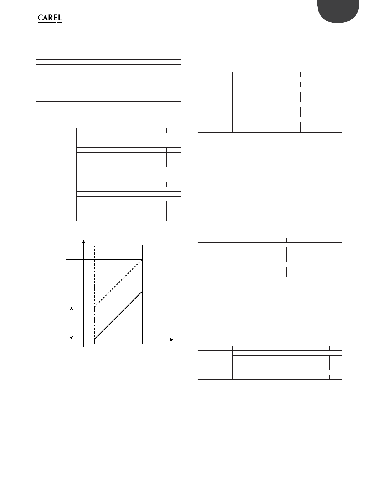
0
100%
Max
0%
Req
Fig. 6.a
Key
Input Input signal Min Input value for min. request
Req Request Max Input value for max request
AOff set
6.10 Access management
The delay after which the Service password (PW1) is requested can be
set, and quick access (Quick menu) to the parameters via the Set point
and On/Off icons disabled (see chap. “User interface”). In addition, a new
password can be set, and the main password PW0 enabled to access any
screen in the programming menu, not only the Service parameters.
Screen index Display description Def Min Max UOM
Gec01 Access management
Password delay 1 0 30 min
Gec02 Access management
Quick menu Yes No Yes Main menu password No No Yes -
Gec03 Access management
Insert new main menu
password (PW0)
0000 0000 9999 -
Gec04 Access management
Insert new service
password (PW1)
0000 0000 9999 -
Tab. 6.j
6.11 Settings
These parameters are set in the event of special needs:
1. to fi lter an excessive number of requests over a certain period, and
avoid numerous starts and stops, enter a longer start delay;
2. if there is no water, it may be useful to extend the delay time before
restarting, to avoid a premature no water alarm;
3. the alarm relay can be normally open (N.O.) or normally closed (N.C.);
the solenoid valve in standby can be set as open or closed;
4. the “drain delay in standby” time is only set if the drain solenoid valve
is selected as open in standby. This determines in delay for opening
the drain solenoid valve after switching to standby. It is useful in the
event of frequent starts/stops, to minimise the time needed to reach
steady operation.
Screen index Display description Def Min Max UOM
Fc01 Settings
Start delay 10 s 0 120
Restart wait 10 min 1 60
Alarm relay logic N.O. N.O. N.C. -
Fc03 Settings
Drain valve in stand-by Open Open Closed Drain delay in stand-by 0 min 60 min
Tab. 6.k
6.12 Network settings
The RS485 serial card (accessory) needs to be installed on the control
board in the “Master” panel. The network parameters need to be set in
the event of connection to a serial network. All the controllers in the
network must be set with the same protocol and communication speed
parameter. By enabling serial control, the humidifi er parameter can be set
over the serial connection.
Screen index Display description Def Min Max UOM
Gd01 BMS confi guration
Protocol Modbus Modbus Carel Speed 19200 1200 19200 bps
Address 1 1 207 -
Gd02 BMS confi guration
Serial manager Disabled Disabled Enabled -
Tab. 6.l
Page 26
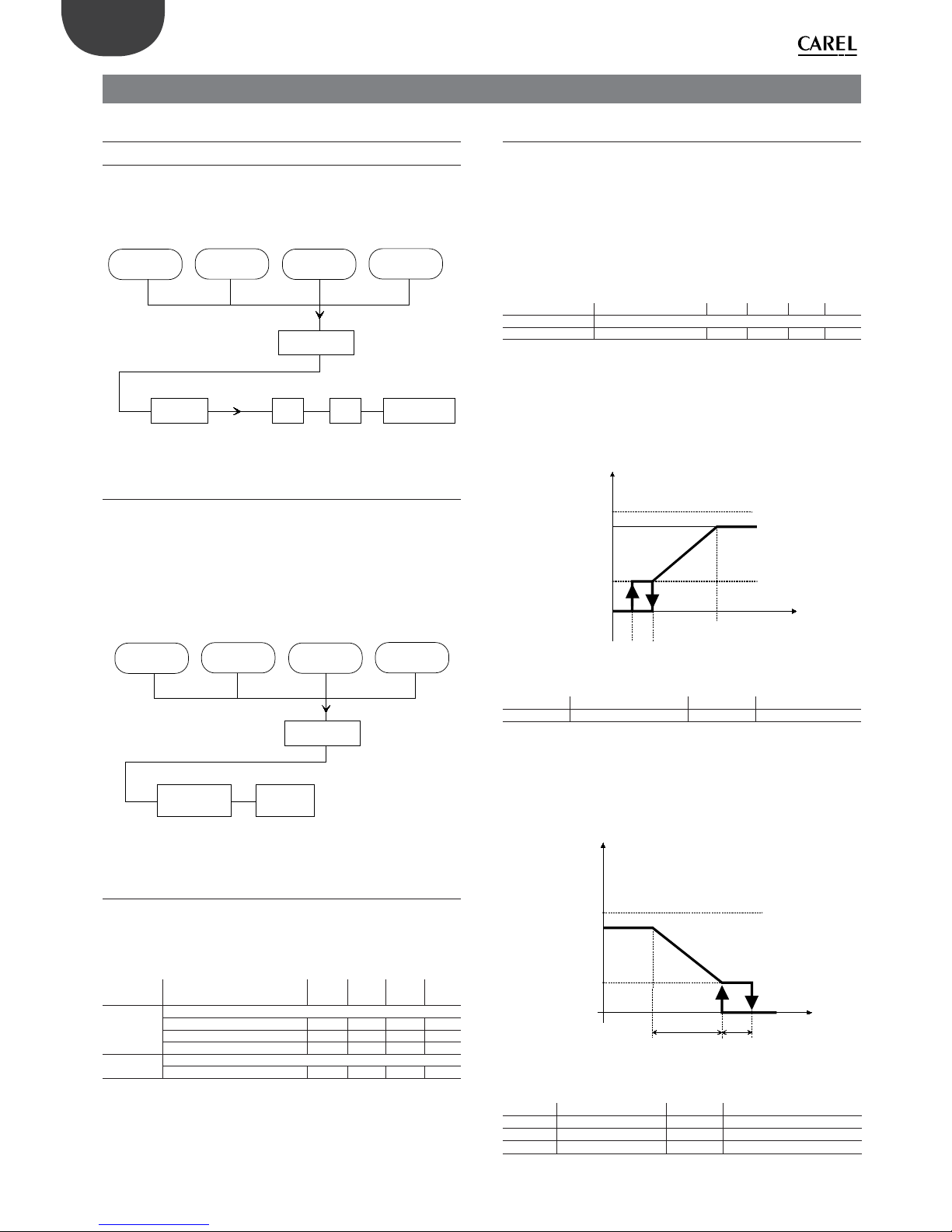
26
ENG
“humiSonic ventilation” +0300063EN - rel. 1.0 - 16.02.2016
7. FUNCTIONS “MASTER” PANEL
7.1 On/Off
7.1.1 ON
At power-on, before beginning atomised water production, humiSonic
temporarily runs the Autotest: to check correct operation of the fl oat level
sensor, the humidifi er per forms a complete tank fi ll cycle and then a drain
complete cycle.
DIGITAL INPUT
KEYBOARD SCHEDULER BMS
AND
START-UP
AUTOTEST
FILLINIT
PRODUCTION
Fig. 7.a
7.1.2 OFF
Before switching from On to Off , humiSonic temporarily runs the
Shutdown procedure, in which the controller deactivates the control
devices and activates the drain valve. Off status involves a logical OR of
the following:
• digital input;
• keypad;
• time band
• BMS.
DIGITAL INPUT
KEYBOARD SCHEDULER BMS
OR
SHUT DOWN
TRANDUCERS
OFF
DRAIN
Fig. 7.b
7.2 Set point
The control and limit set points are set in the “Set point” quick menu.
Based on the type of control, set the control humidity / temperature
probe set point and the limit humidity probe set point. The following
screens are then used to set the control diff erential and hysteresis.
Screen
index
Display description Def Min Max UOM
Fa07 Regulation
Ambient probe
Ambient probe diff erential 10 0 99.9 rH%
Limit probe diff erential 10 0 99.9 rH%
Fa08 Regulation
Reg. hysteresis 10.0 0 99.9 rH%
Tab. 7.a
7.3 Regulation (control)
See chapter “Electrical connections” for the electrical connections to
the “Slave” or “Master” electrical panel, based on the type of control.
The built-in electronic controller on humiSonic features diff erent control
algorithms, which can be selected from the user menu:
On/Off : operation in on/off mode requires the connection of an external
voltage-free contact to input HST (for example, a humidistat, see terminal
block). Unit capacity will therefore be all or nothing, according to the status
of the external contact. The humidistat logic defi nes whether production is
active with the contact closed (N.C.) or with the contact open.
Screen index Display description Def Min Max UOM
Fa10 Regulation
Logic humidos. N.C. N.C. N.O. -
Tab. 7.b
External controller + limit rH%
Capacity modulation is proportional to an external control signal (0 to 1 V,
0 to 5V) and is limited based on the value measured by the limit humidity
probe. This is the typical confi guration for humiSonic installations
connected to a Building Management System that provides a control
signal.
100%
Prod
Max prod
Ext Req
Min prod
5% 5%
Fig. 7.c
Key
Prod Production Min prod Min. production
Max prod Maximum production Ext Req Ext. control signal
External controller
Same as the previous algorithm, however without the humidity probe.
rH% probe
The control probe is normally the supply humidity probe in the air duct.
Max Prod
St
B1/ B2
Prod
100%
HP
Min Prod
Fig. 7.d
Key
Prod Production B1/B2 Control/limit probe
Max prod Max. production P Diff erential
Min prod Minimum production H Hysteresis
St Set point
Page 27
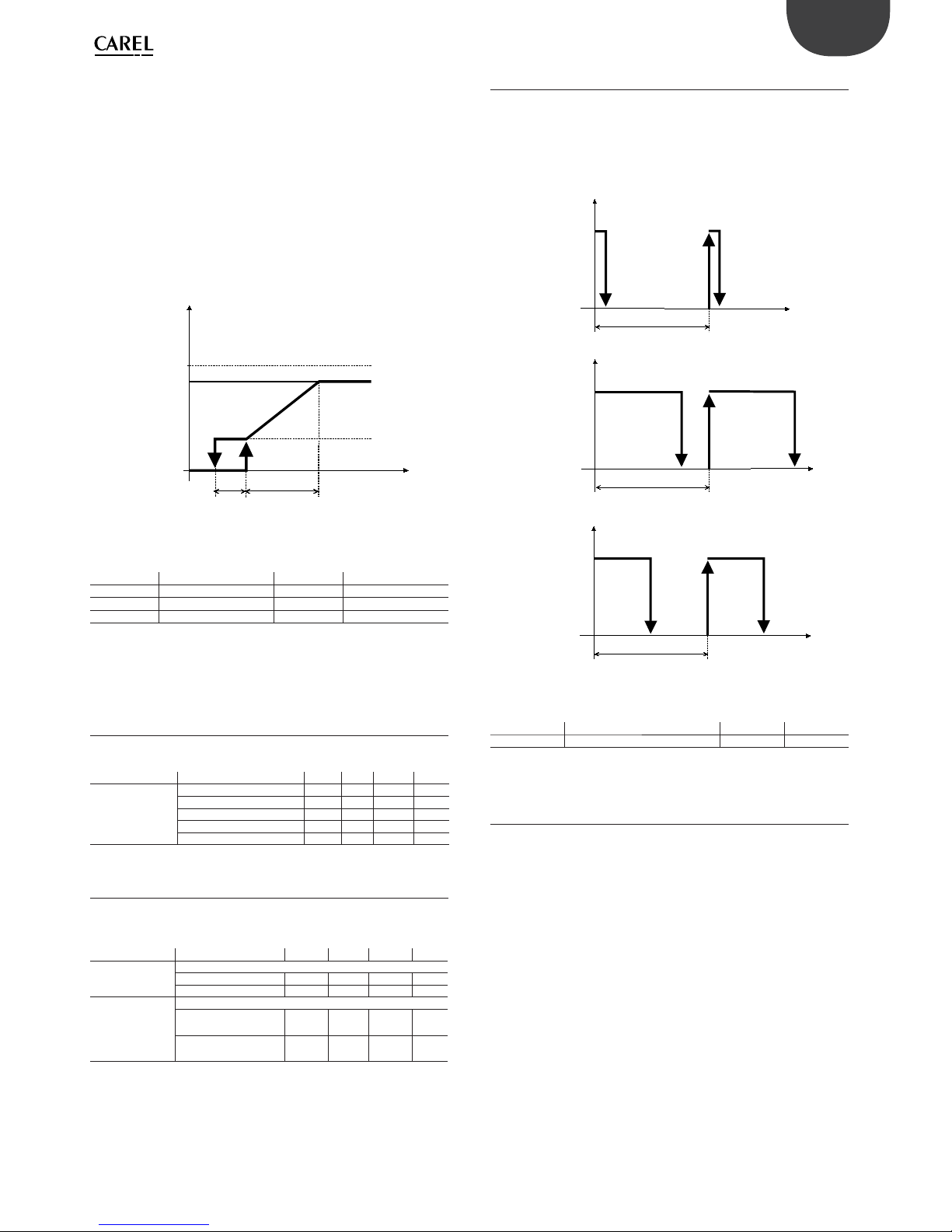
27
ENG
“humiSonic ventilation” +0300063EN - rel. 1.0 - 16.02.2016
rH% probe + limit rH%
As in the previous case with limit humidity probe, normally installed
downstream of the droplet separator. The limit humidity probe is usually
set to a high value, e.g. 80% rH, so as to limit the maximum humidity
level in the ducting and in the room. This is especially recommended
in installations where the air fl ow-rate and temperature and humidity
conditions may vary over time, and consequently an additional safety
feature is useful for preventing the humidifi er from over-humidifying the
air and, in the worst case scenario, leading to condensation in the ducting
downstream of the unit.
T probe
The control probe is normally the supply temperature probe in the air
duct.
Max Prod
B1
Prod
100%
Min Prod
St
H P
Fig. 7.e
Key
Prod Production B1 Temperature probe
Max prod Maximum production P Diff erential
Min prod Minimum production H Hysteresis
St Set point
T probe + limit rH%
As in the previous case, yet with limit humidity probe.
7.4 Probe alarms
The settings of the maximum control probe and limit probe limits
determine activation of the alarms. See the alarm table.
Screen index Display description Def Min Max UOM
Fa09 Regulation
Max ambient humidity 80.0 0 100.0 rH%
Min ambient humidity 0.0 0 100.0 rH%
Max limit humidity 100.0 0 100.0 rH%
Min limit humidity 0.0 0 100.0 rH%
Tab. 7.c
7.5 Flow-rate modulation
Atomised water fl ow-rate is modulated between the minimum and
maximum rated capacity.
Screen index Display description Def Min Max UOM
Fa02 Regulation
Max prod 100 10 100 %
Min prod 10 0 100 %
Fa11 Regulation
Mist modulation
mode
Series Series Parallel -
Mist modulation
period
1 1 10 s
Tab. 7.d
7.7.2 7.5.1 Parallel (dipswitch 8 O )
Atomised water fl ow-rate can be modulated as a percentage from 10%
to 100% (Max prod and min prod) of the rated value, with alternating
starts and stops of the transducers over a set period (modulation period,
default 1 second). The fl ow-rate is set based on the Max Prod parameter
(default 100%) and the request from the external signal (for proportional
control).
Transducer
ON
P
OFF
Production = 10 %
t
Transducer
ON
P
OFF
Production = 50 %
t
Transducer
ON
P
OFF
Production = 75 %
t
Fig. 7.f
Key
Transducer Piezoelectric transducers t time
P Modulation period
If the fl ow-rate is 100%, the transducers are always on.
7.7.3 7.5.2 Series (dipswitch 8 On)
Atomised water fl ow-rate can be modulated as a percentage from 10% to
100% of the rated capacity. Each humidifi er is managed with two groups
of transducers (front and rear) and each line is generates 50% of total
production. If the request is set by the external signal (if proportional
control is active) and the Max prod parameter is 100%, both the lines of
transducers will be activated. For lower output, production will be shared
between the two lines of transducers as follows:
• 51% - 99%: one line of transducers is always activated to generate 50%
of required production, while the other modulates as described in
the previous paragraph to generate the remaining percentage. (e.g.
75% request: one line of transducers is always activated, the other
modulates at 50%);
• 10% - 50%: one line of transducers is always off , the other modulates
as described in the previous paragraph to generate the required
production (e.g. 25% request: one line of transducers is always off , the
other modulates at 50%).
The distribution of production between the two lines of transducers is
rotated every hour of operation so as to avoid non-uniform ageing.
Page 28
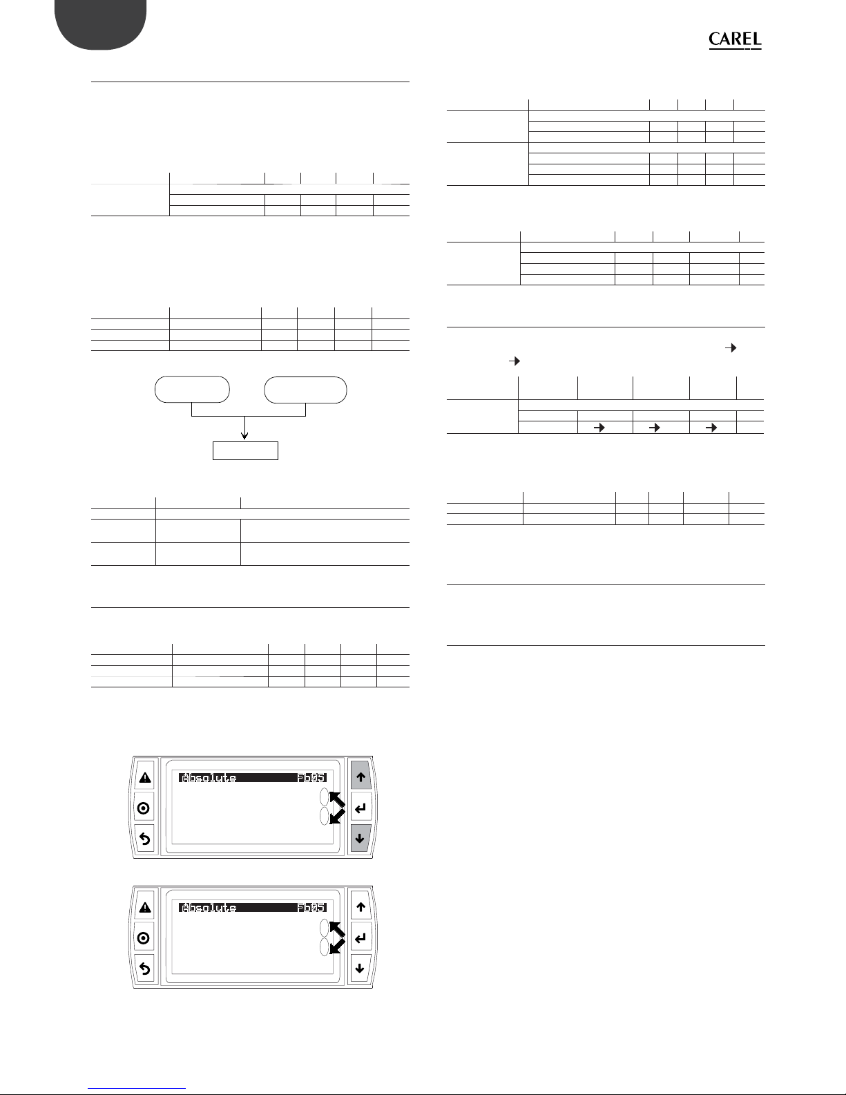
28
ENG
“humiSonic ventilation” +0300063EN - rel. 1.0 - 16.02.2016
7.6 Washing
The washing cycle involves a complete drain cycle, a phase in which fi ll
and drain are activated together to fl ush out any residues in the tank, a
complete fi ll cycle and fi nally another complete drain cycle. During this
operation, atomised water production is stopped.
The washing cycle can be time triggered or event triggered. Once
activated, the washing cycle lasts the time set on screen Fb09.
Screen index Display description Def Min Max UOM
Fb09 Wash settings
Washing time 1 0 10 min
Only if ready ? NO NO YES -
Tab. 7.e
The washing cycle can only be performed if humiSonic is operating (only
if ready ? = YES), or if it is operating or in standby (only if ready ? = NO). It
is assumed that the humidifi er is not operating because it is disabled (see
ON activation conditions). The washing cycle can also be activated on the
screen or via BMS, if enabled.
Screen index Display description Def Min Max UOM
Fb02 Washings
From mask Yes Yes No From BMS Yes Yes No -
Tab. 7.f
TIME TRIGGERED EVENT TRIGGERED
OR
WASHING
Fig. 7.g
Screen index Display description Selection
Fb01 Washings
Time triggered Disabled ¦ Absolute time ¦ Working/ No
working ¦ Scheduled
Event triggered Disabled ¦ From digital input ¦ From
request
Tab. 7.g
7.6.3 Time triggered
Absolute time: the washing cycle is run periodically, and the period is
defi ned on screen Fb05.
Screen index Display description Def Min Max UOM
Fb05 Absolute
Period 24 0 999 h/m
Next wash 24 0 999 h/m
Tab. 7.h
The duration of the period can be expressed in either hours or minutes
(press UP/DOWN to changeover from one to the other), based on the
screen display (it is NOT the sum of the two times).
1ERIODH
/EXT8ASHH
"BSOLUTE'B
1ERIODM
/EXT8ASHM
"BSOLUTE'B
Fig. 7.h
Work / stand by: the type of washing cycle is enabled on screens Fb03/
Fb04; the cycle starts after the corresponding operating period.
Screen index Display description Def Min Max UOM
Fb03 Work wash
Enabled Yes No Yes Work wash period 1 0 480 h/min
Fb04 Nowork wash
Enabled Yes No Yes Nowork period 24 1 480 h/min
Next wash 24 1 480 h/min
Tab. 7.i
Scheduled: the starting time and day are set on screen Fb06.
Screen index Display description Def Min Max UOM
Fb06 Scheduled
Start 00:00 00:00 23:59 Select day ? No No Yes Every Monday Monday Sunday
Tab. 7.j
7.6.4 Event triggered
Digital input: select whether the digital input or the humidistat enables
the action, and whether the event is from open to closed (Off On) or
vice-versa (On Off ).
Screen index Display
description
Def Min Max UOM
Fb07 From DI
Input Humidistat Humidistat Rem. On/Off When
On
Off On Off Off On
-
Tab. 7.k
From request: the request can derive from a probe or a humidistat (rise/
fall = request activated/deactivated).
Screen index Display description Def Min Max UOM
Fb08 From request
When request Rise Rise Fall -
Tab. 7.l
7.7 Timings
The activation times are applied during unit operation and are used by
the controller to detect any malfunctions.
7.7.1 Fill/drain times
Tmax fi ll: maximum fi ll solenoid valve opening time.
The humidifi er detects when there is no feedwater (or the quantity is too
low), by checking the level sensor status after opening the fi ll solenoid
valve. If the tank is empty, and sensor activation is not detected within the
time set by parameter “Tmax fi ll” (default 2 minutes), the humidifi er is not
activated, rather the drain valve opens, after which there is a waiting time
equal to the number of minutes set by parameter “Restart wait” (Fc01,
default 10), during the which is the message is shown on the display:
Waiting (Restart: xx minutes)
xx displays the minutes remaining until restart (starting from the value
set for Fc01), after which there is another refi ll attempt. If this is successful,
production restarts, otherwise there is a further “Restart wait (Fc01)” for
the set number of minutes. The process is repeated until the sensor
detects water is present. For the fi rst two attempts, no alarm is generated,
however if after the third attempt the procedure is not successful, alarm
EF is generated, which is reset automatically when the humidifi er detects
water is present again. If the water fi ll cycle occurs during atomised water
production, see the paragraph “Tmax refi ll”.
Tmax drain: maximum drain solenoid valve opening time.
The humidifi er detects when the water fails to drain (or the level is
too high), by checking the level sensor status after opening the drain
solenoid valve. If sensor activation is not detected within the time set
by parameter “Tmax drain” (default 60 s), the humidifi er keeps the drain
solenoid valve open and activates the wait procedure, as described in
the previous paragraph, displaying alarm Ed. The humidifi er will reset the
alarm and resume normal operation when the low water level is correctly
measured.
Page 29
29
ENG
“humiSonic ventilation” +0300063EN - rel. 1.0 - 16.02.2016
Empty drain T: time during which the drain solenoid valve remains open
after correctly measuring the low water level.
Following the water drain cycle, this is the time that must elapse after the
level sensor measures the low water level to ensure the tank is completely
emptied. This is useful if for parameter Fc03 the drain solenoid valve has
been selected as closed in standby.
Screen index Display description Def Min Max UOM
Gea01 Timings
Tmax fi ll 2 0 30 min
Tmax drain 60 0 30 s
Empty drain T. 30 0 60 s
Tab. 7.m
Production, refi lling times
Tmax prod: maximum atomised water production time (drivers active),
during which the level sensor must signal low water level.
Max Hlev time: maximum time for measuring the high water level.
The humidifi er checks the water level in the tank during production of
atomised water. If the level does not fall, the following faults may have
occurred:
1. piezoelectric transducer malfunction;
2. leaking fi ll solenoid valve;
3. fan malfunction.
If after the time set for Tmax prod (in minutes, default 30), the low water
level has not been reached, atomised water production is stopped and
the wait procedure starts (see the description in Tmax fi ll), after which the
control attempts to resume production. If the condition remains, alarm
EP will be activated, shutting down the unit. If after a percentage of Tmax
prod, set on screen Gea03 (default 70%) the water level is above the high
level for a time equal to “Max Hlev time”, atomised water production stops
and warning EL is generated. The wait procedure then starts, after which
the controller will attempt to restart production. Warning EL is reset at the
end of a production cycle that ends correctly. Alarm EL is also generated
during standby if an abnormal water level is measured (the water level
diff ers from the level measured when switching to standby, for a time
equal to Max Hlev time).
Tmin prod: minimum atomised water production time (driver active)
during which the low level sensor must not be activated.
Tmin prod sets a minimum production time (default 1 minute). If the
production cycle lasts less than this time, the drain solenoid valve may
not be tight or the fi ll solenoid valve fl ow-rate may be too low. The
controller, in this case, activates the following procedures:
1. at the end of the fi rst cycle, ending after less than Tmin prod, the Refi ll
time is increased (50% more than Refi ll time) and the drain solenoid
valve is powered at a higher voltage to try and increase tightness;
2. at the end of the second cycle, ending after less than Tmin prod,
the water refi ll time is further increased (100% more than Refi ll time)
and chattering* of the drain solenoid valve is activated during the fi rst
automatic washing cycle;
3. at the end of the third cycle, ending after less than Tmin prod, the
water refi ll time is further increased (150% more than Refi ll time) and
a washing cycle is performed, including chattering* as activated in
the previous step. Warning Ed will also be generated.
4. following the last stage, a new production cycle will be performed.
If the cause of the error persists, the controller will start the procedure
from the beginning again, until it a full cycle is completed within the
defi ned times. Any warnings will also be reset.
*Chattering: series of rapid opening/closing cycles of the drain solenoid valve,
aimed at removing any residues (scale, dust, etc.) that prevent it from closing
correctly.
Screen index Display description Def Min Max UOM
Gea04 Timings
Low lev delay 10 0 200 s
MaxHLev Time 10 1 60 s
Tab. 7.n
Refi ll time: time the fi ll solenoid valve is kept open for, after the control
level (intermediate) has been reached during atomised water production.
Tmax refi ll: maximum time the drivers remain active for during a water
refi lling cycle, after the level sensor has measured the low water level
during atomised water production.
The piezoelectric transducers, by nature, if operated without water,
will be quickly damaged until failing. To prevent this from happening,
the controller ensures, via the level sensor, that even in the event of
malfunctions the transducers are never activated without water present.
When starting with an empty tank, the transducers are only activated
when the low level is measured and, subsequently, the “Refi ll time” has
elapsed. During refi lling when the unit is operating, that is, after the low
level has fallen due to atomised water consumption with consequent
activation of the fi ll solenoid valve, if the level is not restored before the
“Tmax refi ll” time, the transducers are switched off , while the fi ll cycle
continues until:
1) the level has been restored and the “Refi ll time” has elapsed. The
transducers are then reactivated
2) on activation of the fi ll valve, the time set for Tmax fi ll must elapse.
Then the wait procedure will be activated, as described previously.
If, on the other hand, the level is correctly restored within the “ Tmax refi ll”
time, the transducers remain on and the fi ll cycle continues until the end
of the Refi ll time.
Screen index Display description Def Min Max UOM
Gea02 Timings
Tmax refi ll 10 1 60 s
Refi ll time 10 0 120 s
Gea03 Timings
Tmax prod 30 1 200 min
Tmin prod 1 1 200 min
Tab. 7.o
Low lev delay: low level fi ltering time for activating the fi ll cycle.
The fl oat sensor must remain active for the time set by Low lev delay
before the fi ll cycle (Refi ll) or the complete emptying timer (Empty Drain)
is activated).
Unit offl ine alarm times
Remote board offl ine time: time after which the remote unit is deactivated
(standby) if there is no serial connection with the control panel.
The remote unit checks communication status with the “Master” panel,
and if for some reason there is no communication for the time set for
the parameter, the unit goes into “safety” mode, that is, atomised water
production is stopped and the drain cycle is activated.
Main board offl ine time: time after which the control panel generates
the “Remote unit offl ine” alarm if no serial communication is detected.
If the “Main board offl ine time” elapses, and the control panel continues
to not receive a response, the “Remote unit offl ine” alarm is activated. In
this status, atomised water production can no longer be activated.
Screen index Display description Def Min Max UOM
Gea05 Timings
Remote board offl ine time 10 0 240 s
Main board offl ine time 30 0 999 s
Tab. 7.p
Page 30
30
ENG
“humiSonic ventilation” +0300063EN - rel. 1.0 - 16.02.2016
8. PARAMETERS TABLE “MASTER” ELECTR. PANEL
Mask Display description Notes Def. UOM Min Max Value description Type R/W
Press UP/DOWN to display the Info icon and then press Enter to access the Information quick menu
Info
i01 Humidifi er size 0,5 kg/h 0,5 18 I R
Next wash - h IR
i02 Work hours counter - h IR
Machine hours counter - h IR
i03 Water level sensor state - - Low High Low ¦ Work ¦ High I R
i04 Dip-switch state R
A. On/Off Unit
A01 On/Off
Enable No - No Yes No ¦ Yes D R/W
Autotest Yes - No Yes No ¦ Yes D R/W
Manual wash No - No Yes No ¦ Yes D R/W
Max Prod 100 % 10 100 I R/W
B. Setpoint
B01 Setpoint Fa01=reg. with probe 50.0 rH % / °C 10.0 80.0 I R/W
Limit 90.0 rH % 0 100.0 I R/W
C. Clock/ Scheduler
C01 Clock
Day Monday day Monday Sunday - I R
Date 01/01/2015 dd/mm/yy --/--/---- --/--/---- dd/mm/yy I R/W
Hour hh:mm hh:mm 00:00 23:59 hh:mm I R/W
C02 Clock
DST (daylight saving time): Enable - Enable Disable D R/W
Transition time 60 min 0 240 I R/W
Start: Last - First Last First ¦ ...¦ Fourth¦ Last I R/W
Sunday day Monday Sunday Monday ¦ ...¦ Sunday ¦ *** I R/W
in March month January -- January ¦ ... ¦ December ¦ - - I R/W
at 2.00 hour 0.00 23.00 I R/W
End: Last - First Last First ¦ ...¦ Fourth¦ Last I R/W
Sunday day Monday *** Monday ¦ ...¦ Sunday I R/W
in October month January December January ¦ ... ¦ December I R/W
at 3.00 ora 0.00 23.00 I R/W
C03 Scheduler
Enable scheduler ? No - No Yes No ¦ Yes D R/W
C04 Time bands (press Enter and UP/DOWN to check the box)
Day Monday - Monday Sunday Monday ¦ ...¦ Sunday I R/W
Time 1 hh/mm 00:00 23:59 I R/W
Off -Off On+Set Off ¦ On ¦ On +Set I R/W
Humidity set point %rH 0 100 I R/W
Time 2 hh/mm 00:00 23:59 I R/W
Off -Off On+Set Off ¦ On ¦ On +Set I R/W
Humidity set point %rH 0 100 I R/W
Time 3 hh/mm 00:00 23:59 I R/W
Off -Off On+Set Off ¦ On ¦ On +Set I R/W
Humidity set point %rH 0 100 I R/W
Time 4 hh/mm 00:00 23:59 I R/W
Off -Off On+Set Off ¦ On ¦ On +Set I R/W
Humidity set point %rH 0 100 I R/W
Time 5 hh/mm 00:00 23:59 I R/W
Off -Off On+Set Off ¦ On ¦ On +Set I R/W
Humidity set point %rH 0 100 I R/W
Time 6 hh/mm 00:00 23:59 I R/W
Off -Off On+Set Off ¦ On ¦ On +Set I R/W
Humidity set point %rH 0 100 I R/W
D. Master/Slave
Slave Manager
E. Data logger
E01 Data logger
N° - - 001 50 Nr. alarm I R
Hour - hour : min 00:00 23:59 Time of alarm activation I R
Date - dd : mm : yy 01 : 01 : 00 01 : 01 : 00 Date of alarm activation I R
F. User
User menu
a. Regulation
Fa01 Regulation
Regulation type Probe rH%+limit
rH%
- On/Off Probe T+Limit
rH%
On/Off ¦ Ext.regulator ¦ Ext.
regulator+limit rH% ¦ Probe rH% ¦
probe rH%+Limit rH% ¦ Probe T ¦
Probe T+Limit rH%
I R/W
Unit of measure °C-Kg/h °C-Kg/h °F-lb/h °C-Kg/h ¦ °F-lb/h D R/W
Fa02 Regulation
Max Prod 100 % 10 100 I R/W
Max Prod 100 % 10 100 I R/W
Min Prod 10 % 0 100 I R/W
Fa03 Regulation
Ambient probe Analog - Analog HYHU000000 Analog ¦ HYHU000000 D R/W
Page 31
31
ENG
“humiSonic ventilation” +0300063EN - rel. 1.0 - 16.02.2016
Mask Display description Notes Def. UOM Min Max Value description Type R/W
Fa04 Regulation
Ambient probe (AI7)
Type 0...1 V - 0...1 V 0...1 V¦ 0...5 V
¦ NTC
I R/W
Off set 0.0 -100.0 100.0 I R/W
Min 0.0 0.0 100.0 I R/W
Max 100.0 0.0 100.0 I R/W
Alarm delay 0 s 0 999 I R/W
Fa05 Regulation Fa03=HYHU...
Ambient probe (TH)
Type rH%+T
Off set 0.0 -20.0 50.0 I R/W
Fa06 Regulation Fa01: reg.=...+lim.rH%
Limit probe (AI6)
Type 0...5 V - 0...1 V 0...1 V¦ 0...5 V I R/W
Off set 0.0 -100.0 100.0 I R/W
Min 0.0 0.0 100.0 I R/W
Max 100.0 0.0 100.0 I R/W
Alarm delay 10 s 0 999 I R/W
Fa07 Regulation Fa01: reg.=probe (+lim.rH%)
Ambient probe diff erential 10 rH%/°C 0 99.9 I R/W
Limit probe diff erential 10 rH% 0 99.9 I R/W
Fa08 Regulation Fa01: reg.=probe ...
Reg. hysteresis 10.0 % 0 99.9 I R/W
Fa09 Regulation Fa01: reg.=probe (+lim.rH%)
Max amb. H/T 80.0 rH%/°C 0 100.0 I R/W
Min amb. H/T 0.0 rH%/°C 0 100.0 I R/W
Max Lim. Hum. 100.0 rH% 0 100.0 I R/W
Min Lim. Hum. 0.0 rH% 0 100.0 I R/W
Fa10 Regulation Fa01: reg.=On/Off
Logic humidos. N.C. - N.C. N.O. N.C: production if closed contact I R/W
Fa11 Regulation
Mist modulation mode Serie - Serie Parallel See DIP-SWITCH settings I R
Mist modulation period 1 s 1 10 I R/W
b. Washings
Fb01 Washings
Time triggered Time or event triggered
(OR condition)
Absolute time - Disabled Scheduled Disabled ¦ Absolute time ¦ Working/
No working ¦ Scheduled
I R/W
Event triggered Disabled - Disabled From request Disabled ¦ From digital input ¦ From
request
I R/W
Fb02 Washings
From mask Yes - Yes No Yes ¦ No I R/W
From BMS Yes - Yes No Yes ¦ No I R/W
Fb03 Work wash Fb01=
working/ no
working
Enabled Yes No Yes Yes ¦ No I R/W
Work wash period 1 min 1 480 I R/W
Fb04 Nowork wash
Fb01= working/no
working
Enabled Yes - No Yes Yes¦ No I R/W
Nowork period 24 h/m 1 480 I R/W
Next wash 24 h/m 1 480 I R/W
Fb05 Absolute
Fb01= absolute time
Period 24 h/m 0 999 I R/W
Next wash 24 h/m 0 999 I R/W
Fb06 Scheduled Fb01=Progr.
Start 00:00 hh/min 00:00 23:59 I R/W
Select day ? No No Yes D R/W
Every Monday Monday Sunday I R/W
Fb07 From DI Fb01=da DI
Input Humidostat Humidostat Rem. On/Off D R/W
When Activ. event On --> Off On --> Off Off --> On D R/W
Fb08 From request Fb01=from request
When request Rise - Rise Falls D R/W
Fb09 Wash settings Fb01=abs. time
Washing time 1 min 0 10 I R/W
Only if ready ? No No Yes D R/W
c. Settings
Fc01 Settings
Start delay 10 s 0 120 I R/W
Restart wait 10 min 1 60 I R/W
Fc02 Settings
Alarm relay logic N.O. - N.O. N.C. D R/W
Status relay Production Production Maintenance Production ¦ Maintenance I R/W
Logic N.O. - N.O. N.C. D R/W
Fc03 Settings
Drain valve in stand-by(*) Open - Open Closed D R/W
Drain delay in stand-by (*)=Open 0 min 0 60 I R/W
G. Service
a. Change language
Language Italian - English Italian D R/W
b. System information
Gb01 Information
FLSTDMHUSU SW name
Version 0.3.008B
Date - dd/mm/yy Date software release I R
Bios dd/mm/yy BIOS release date I R
Boot dd/mm/yy BOOT release date I R
Page 32
32
ENG
“humiSonic ventilation” +0300063EN - rel. 1.0 - 16.02.2016
Mask Display description Notes Def. UOM Min Max Value description Type R/W
Gb02 Information
Board type --Board size --Total fl ash 2048 KB I R
RAM 512 KB I R
Built-in type None IR
Main cycle - ms I R
Gb03 Firmw. release - IR
HW Id - IR
Functional Test - IR
c. Working hours
Gc01 Work counter 0 h 0 32767 I R/W
Machine counter 0 h 0 32767 I R/W
Gc02 Hours counter
Maintenance hours 5000 h 0 20000 I R/W
Remainder every 60 min 0 240 I R/W
d. BMS confi guration
Service password
Insert service password
(PW1)
Gd01 BMS confi guration
Protocol Modbus - Modbus Carel Modbus ¦ Carel D R/W
Speed 19200 bps 1200 19200 1200 ¦ 2400 ¦ 4800 ¦ 9600 ¦ 19200 I R/W
Address 1 - 1 207 I R/W
Gd02 BMS confi guration
Serial manager Disabled Disabled Enabled Disabled ¦ Enabled D R/W
e. Service settings
a. Timings
Gea01 Timings
Tmax fi ll 2 min 0 30 I R/W
Tmax drain 60 s 0 300 I R/W
Empty Drain T. 30 s 0 60 I R/W
Gea02 Timings
Tmax Refi ll 5 s 1 60 I R/W
Refi ll time 5 s 0 120 I R/W
Gea03 Timings
Tmax prod. 30 min 1 200 I R/W
Level test at
Tmax production
70 % 50 90
Tmin prod. 1 min 1 200 I R/W
Gea04 Timings
Low lev delay 10 s 0 200 I R/W
Max HLev Time 10 s 1 60 I R/W
Gea05 Timings
Remote board offl ine time 30 s 0 240 I R/W
Main board offl ine time 30 s 0 999 I R/W
b. Reset / Default
Geb01 Reset Cnt/Logs
Delete data logger No - No Yes No ¦ Yes D R/W
Reset counter No - No Yes No ¦ Yes D R/W
Geb02
DEFAULT INSTALLATION:
erase user settings and
install global default value
(“Master” panel)
No - No Yes No ¦ Yes D R/W
Geb03 Install default parameters
on remote unit
(humidifi er)
No - No Yes No ¦ Yes D R/W
c. Access management
Gec01 Access management
Password delay 1 min 0 30 D R/W
Gec02 Access management
Quick menu Yes - No Yes No ¦ Si D R/W
Main menu password No No Yes No ¦ Si D R/W
Gec03 Access management
Insert new main menu
password (PW0)
0000 0000 9999 I R/W
Gec04 Access management
Insert new service
password (PW1)
0000 0000 9999 I R/W
f.
Manual management
Gf01 Manual mode
Manual mode No - No Yes No ¦ Yes D R/W
Gf02 Manual management Gf01:mod=si
Fill Off -Off On Off ¦ On D R/W
Drain On - Off On Off ¦ On D R/W
Gf03 Manual management
Mist 1 No - No Yes No ¦ Yes D R/W
Mist 2 No - No Yes No ¦ Yes D R/W
Alarm relè On - Off On Off ¦ On D R/W
Gf04 Manual management
Ambient probe 0 - 0 1000 I R/W
Limit probe 0 - 0 1000 I R/W
Tab. 8.a
Page 33
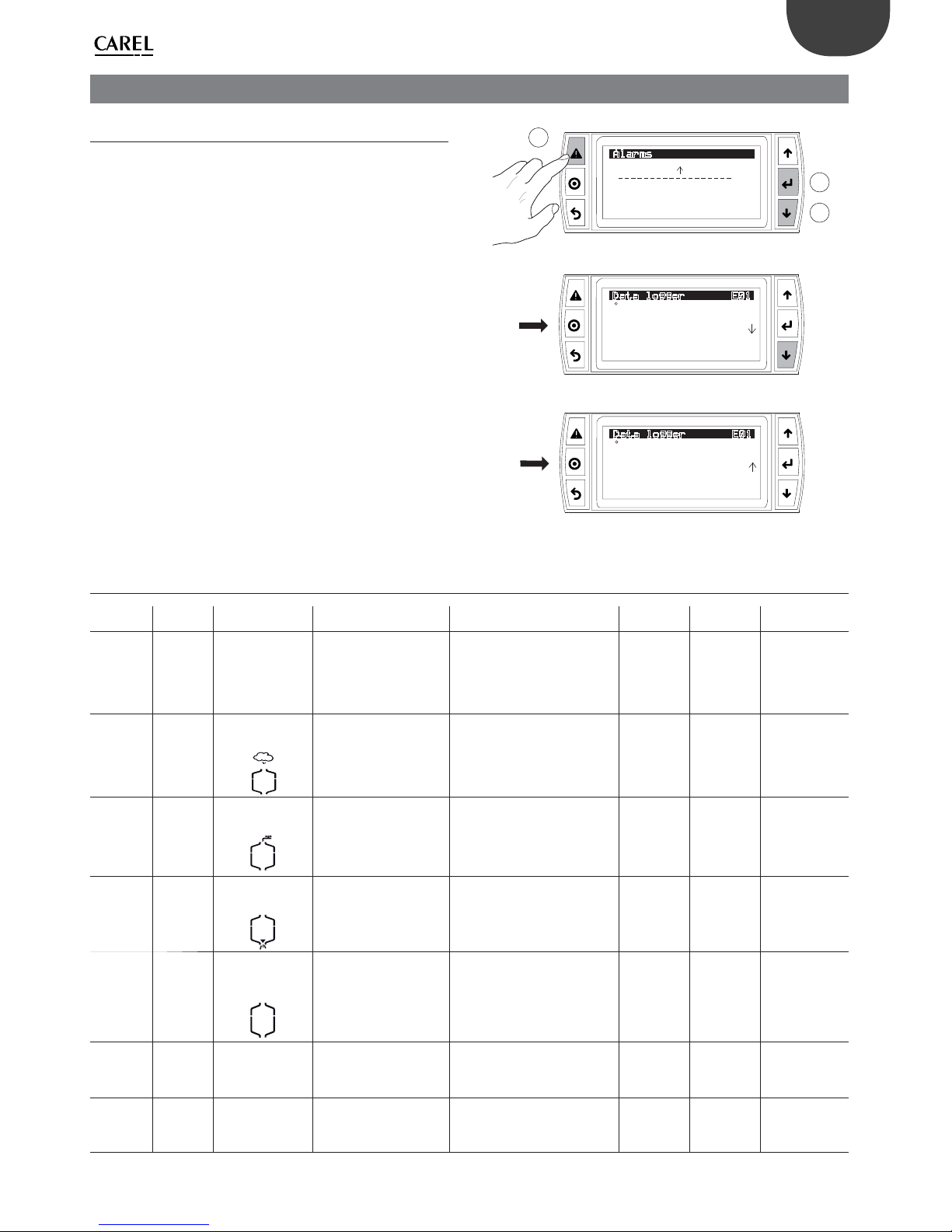
33
ENG
“humiSonic ventilation” +0300063EN - rel. 1.0 - 16.02.2016
9. ALARMS
9.1 Types of alarms
There are two types of alarms:
• manual reset;
• automatic reset: the alarm is reset and the unit restarts automatically
when the alarm condition is no longer present;
When an alarm occurs, the Alarm button fl ashes and the display shows
the standard display.
Press Alarm to display a short description of the alarm.
Press Alarm again to attempt to reset the alarm:
1. if the cause is no longer present, the alarm should be reset and the red
light on the button will go off ;
2. if the reset attempt fails, the Alarm button stays on steady, signalling that
the alarm has been acknowledged.
If the alarm is reset automatically, the Alarm button goes off and the
alarm reset event is recorded in the alarm log.
Example: the high humidity alarm is visible in the list of alarms, and the
log shows the activation event (down arrow) and reset event (up arrow).
"LARMS
)
)IGH)UMIDITY
%ATALOGGER&
/
)>)IGHHUMIDITY
%ATALOGGER&
/
)>)IGHHUMIDITY
A
B
C
Fig. 9.a
9.1 Alarm table
Source “Slave”
electr. panel
“Master” electrical
panel
Cause Solution Alarm relay
activation
Action Reset
Humidifi er 2 fast fl ashes
Et
_________________
Autotest failed
• Feedwater not connected or
insuffi cient
• drain open
• fl oat failure
Check:
• feedwater and fi ll valve;
• blockage of the fi lter on the fi ll
solenoid valve;
• check drain solenoid valve and
drain connection;
yes humidifi cation
stopped
ESC (“Master”)
Humidifi er 5 fast fl ashes
EP
_________________
no production
Piezoelectric transducer
malfunction
Perform maintenance on the case yes humidifi cation
stopped
ESC (“Master”)
Humidifi er 3 fast fl ashes
EF
_________________
no water
Mains water interruption or fi ll
solenoid valve malfunction
Check:
• feedwater and fi ll valve;
• blockage of the fi lter on the fi ll
solenoid valve;
yes (in the 10
minute waiting
period)
humidifi cation
stopped for 10
minutes only
automatic (after 10
minute wait)
Humidifi er 4 fast fl ashes
Ed
_________________
drain failure
Drain circuit/solenoid valve
malfunction
Check drain valve and drain
connection
yes humidifi cation
stopped
ESC (“Master”)
Humidifi er
5 slow
fl ashes
CL
_________________
tank maintenance
request signal
1500 operating hours
exceeded for recommended
maintenance
Carry out maintenance on tank and
transducers (chap. 10)
no signal only Reset hour counter
(Geb01)
“Master”
panel
-
Ambient probe
_________________
Probe broken or
incorrectly connected
Cable interrupted/
disconnected/incorrectly
connected.
Check the reference signal yes humidifi cation
stopped
AUTO
“Master”
panel
-
Limit probe
_________________
Probe broken or
incorrectly connected
Cable interrupted/
disconnected/incorrectly
connected.
Check the reference signal yes humidifi cation
stopped
AUTO
Page 34
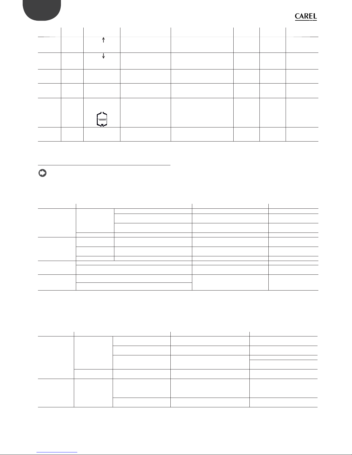
34
ENG
“humiSonic ventilation” +0300063EN - rel. 1.0 - 16.02.2016
Source “Slave”
electr. panel
“Master” electrical
panel
Cause Solution Alarm relay
activation
Action Reset
“Master”
panel
-
H
_________________
High humidity
The signal from the probe
indicates a humidity higher
than 80%rH
Check humidity probe signal/cable yes signal only AUTO
“Master”
panel
-
H
_________________
Low humidity
The signal from the probe
indicates a humidity lower
than 20%rH
Check humidity probe signal/cable yes signal only AUTO
Humidifi er
2 slow
fl ashes
EE
_________________
EEPROM alarm
EEPROM problems If the problem persists, contact the
CAREL service centre
yes humidifi cation
stopped
If the fault persists,
contact service
Humidifi er 1 fast fl ash
E0
_________________
Remote unit
Functional test not complete
in the factory / EEPROM
problems
If the problem persists, contact the
CAREL service centre
yes humidifi cation
stopped
If the fault persists,
contact service
Humidifi er 8 fast fl ashes
EL
_________________
Water level alarm
Level too high during
atomised water production
due to:
• fi ll SV leaks
• transducer malfunction
Check:
• fi ll SV
• transducers
yes humidifi cation
stopped
AUTO
“Master”
panel
-
Offl ine
_________________
Remote unit offl ine
The panel does not detect
communication with the
remote unit
Check:
• serial connection cable
• power cable
yes humidifi cation
stopped
AUTO
Tab. 9.a
9.2 Troubleshooting
Note: if the problem identifi ed cannot be solved using the following
guide, contact CAREL technical service.
1. Firstly, check the humidifi er and the surrounding area.
Problem Cause Check Solution
No atomised water
production
Power supply Humidifi er switch in the OFF position Check the switch Switch ON
No power Measure the voltage at the humidifi er input
terminals
Connect power
Power supply fault Measure the voltage at the power supply
output terminals
Replace the power supply
Feedwater system Valve closed upstream Check Open the valve
The quantity of
atomised water is
too low
Power supply Low power supply voltage Check the voltage at the power supply output
terminals
Replace the power supply, if
damaged
Feedwater system Water level during production is too high and
overfl owing
Check visually See table 2)
Other The humidifi er is not installed horizontally Check visually Adjust
No atomised water
production
Dust and foreign matter accumulated in the tank (*) Clean the inside of the tank
Transducer deterioration The average life of the transducer is around
10,000 to 15,000 operating hours
Replace
The quantity of
atomised water is
too low
Dust and foreign matter accumulated in the tank (*) Visually check the inside of the tank Clean the inside of the tank
and replace the transducers
Scale build-up on the surface of the piezoelectric transducers (*)
Tab. 9.b
(*) These malfunctions can be avoided by carrying out preventive maintenance.
2. If the cause has not been identifi ed with the previous checks, there
may be faulty components. Check the inside of the humidifi er.
Problem Cause Check Solution
No atomised water
production
Feedwater system Float level sensor fault Empty the tank, remove the electronic board
and check continuity of the level sensor
Contact service to replace the level
sensor
Float level sensor blocked Clean the sensor. If normal operation is
not restored, replace
Fill valve fault No water fi lled even when the tank has been
emptied
Replace the valve
Clean the sensor. If normal operation is
not restored, replace
Other The fan cables are loose or
detached
Check connection after removing the
humidifi er cover
Restore correct connection to the
terminals
The quantity of
atomised water is
too low
Water level overfl ow Float level sensor blocked If the water level in the tank reaches the
overfl ow pipe, remove the connector from the
control board and check continuity of the level
sensor
If there is continuity, contact service to
replace the level sensor
Fill valve fault Water is fi lled even after switching off the
appliance
Replace the fi ll valve
Tab. 9.c
Page 35
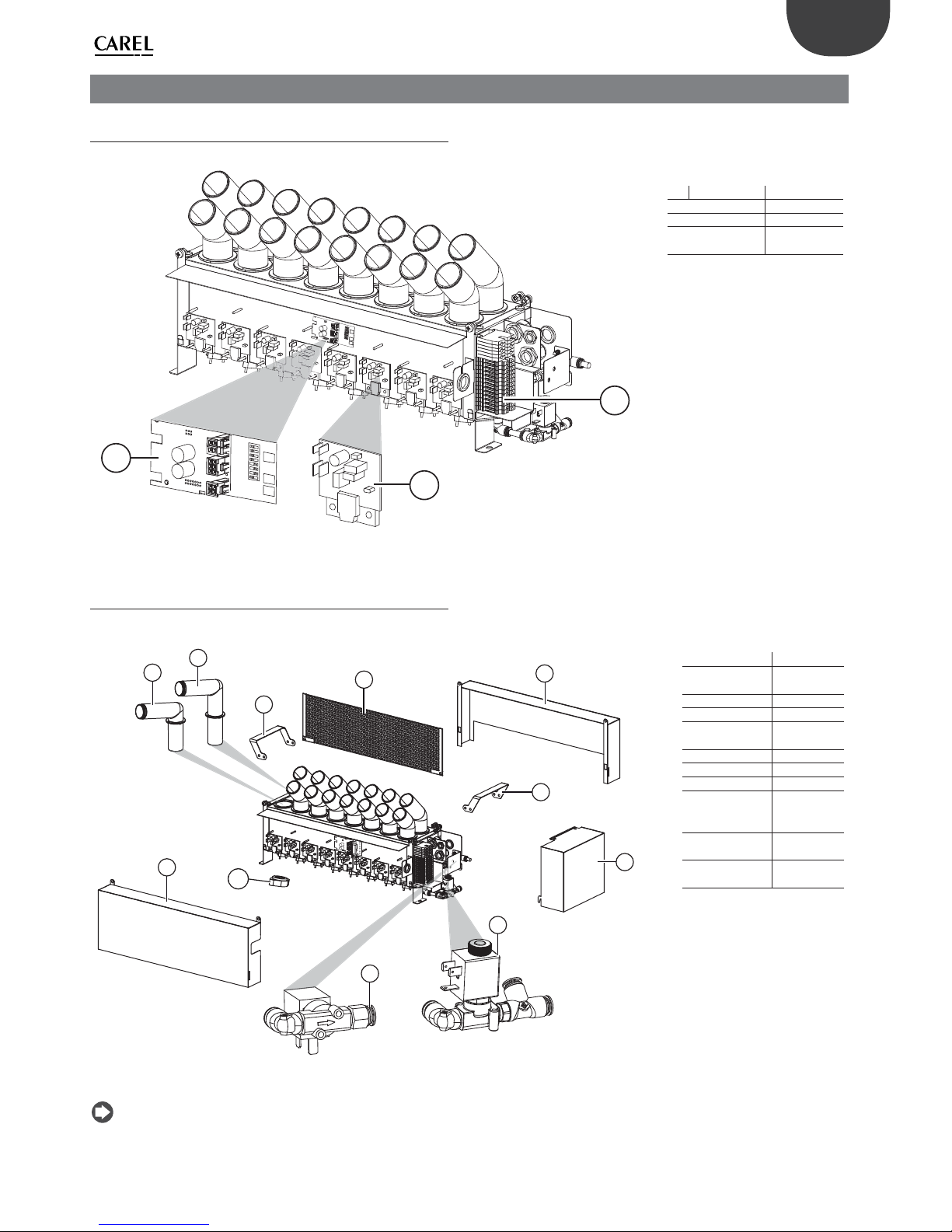
35
ENG
“humiSonic ventilation” +0300063EN - rel. 1.0 - 16.02.2016
10. MAINTENANCE AND SPARE PARTS
10.1 Electrical components
3
2
1
Key:
no. Description Spare part no.
1 Terminal block 2 Driver board UUKDE00000
3 Electronic
control board
UUF*D0000
Tab. 10.a
Fig. 10.a
10.2 Mechanical components
6
7
1
2
3
10
5
8
9
1
4
Legenda:
no. Description Spare part no.
1 Lifting
handle
-
2 Baffl e 3 Rear cover 4 Terminal
block cover
-
5 Front cover 6 Front diff user UUKDA00000
7 Rear diff user UUKDR00000
8 Drain
solenoid
valve kit
UUKDN00000
9 Fill solenoid
valve kit
UUKFR00000
10 Piezoelectric
transducer
UUKTP00000
Tab. 10.b
Fig. 10.b
Note: maintenance on the humidifi er must be carried out by CAREL
technical service or other professionally qualifi ed personnel
Page 36
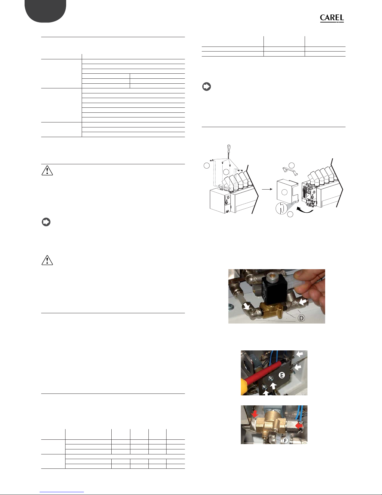
36
ENG
“humiSonic ventilation” +0300063EN - rel. 1.0 - 16.02.2016
10.3 System information
This screen shows the currently installed software revision, the memory
usage and the cycle time.
Screen index Display description
Gb01 Information
FLSTDMHUSU
Version
Date Software release date
Bios BIOS release date
Boot BOOT release date
Gb02 Information
Board type
Board size
Total fl ash
RAM
Built-in type
Main cycle
Gb03 Firmware release
HW Id
Functional test
Tab. 10.c
10.4 Maintenance
Important: before performing any operations:
• power the unit off at the switch (off ) on the control panel;
• empty the water from the tank.
The fi ll valve is normally closed and the drain valve is normally open,
consequently, when powering down the humidifi er, the unit is drained
automatically.
Note: preventive maintenance on the humidifi er is recommended
to ensure optimum system performance. Maintenance includes:
• checking tightness of the electrical connectors;
• cleaning and visual inspection of the components;
• checking water level and making sure there are no leaks.
Important:
• the piezoelectric transducer is very delicate: when cleaning the inside
of the tank, make sure not to scratch it, for example with a screwdriver;
• tighten the nuts applying the maximum allowed torque (4 ± 0.5
kg·cm). Excessive tightening torque may damage the humidifi er.
10.5 Maintenance operations
Routine maintenance on humidifi ers operating on demineralised water
involves cleaning all the parts in contact with the water:
a. fi ll/drain lines;
b. water tank.
Special maintenance and repairs involve replacement of:
a. fi ll/drain solenoid valve;
b. driver board;
c. piezoelectric transducer;
d. electronic control board.
10.6 Maintenance intervals
Maintenance intervals depend on water quality and the quantity
of atomised water produced. An operating hour counter (eff ective
production) and a unit operating hour counter (total hours) can be set,
together with a maintenance hour counter, after which the display shows
a warning message. See alarm CL.
Screen
index
Display description Def Min Max UOM
Gc01 Hour counter
Work counter 0 0 32767 h
Machine counter 0 0 32767 h
Gc02 Hour counter
Maintenance hours 5000 0 20000 h
Reminder every 60 0 240 min
Tab. 10.d
Mains water
Water hardness 15…25 °f
(150 …250 μS/cm)
25…40 °f
(250 to 400 μS/cm)
Daily operating hours 8…10 8…10
Maintenance operations/year 2 3
Tab. 10.e
Demineralised water
The use of demineralised water minimises maintenance requirements.
Note: it is recommended to perform special maintenance and
repairs at least once a year, irrespective of the number of operating hours
shown on the operating hour counter.
10.7 Replacing the components
Drain solenoid valve
To remove the right side cover:
V
A
C
B
M
Fig. 10.c
1. loosen and remove the screws (A) and release the cover (C) at point (B)
to remove. If necessary, loosen the screws (V) to remove the lifting
handle (M);
2. unplug the electrical connectors and move the spring fasteners so as to
remove the hoses, then remove the block (D): elbow connector, drain
valve, T-connector.
Fig. 10.d
Fill solenoid valve
1. loosen and remove the screws (arrows) so as to remove the bracket (E);
Fig. 10.e
Fig. 10.f
2. unplug the electrical connectors and move the spring fasteners so
as to remove the hoses, then remove the block (F): elbow connector,
fi ll valve, connector.
Page 37
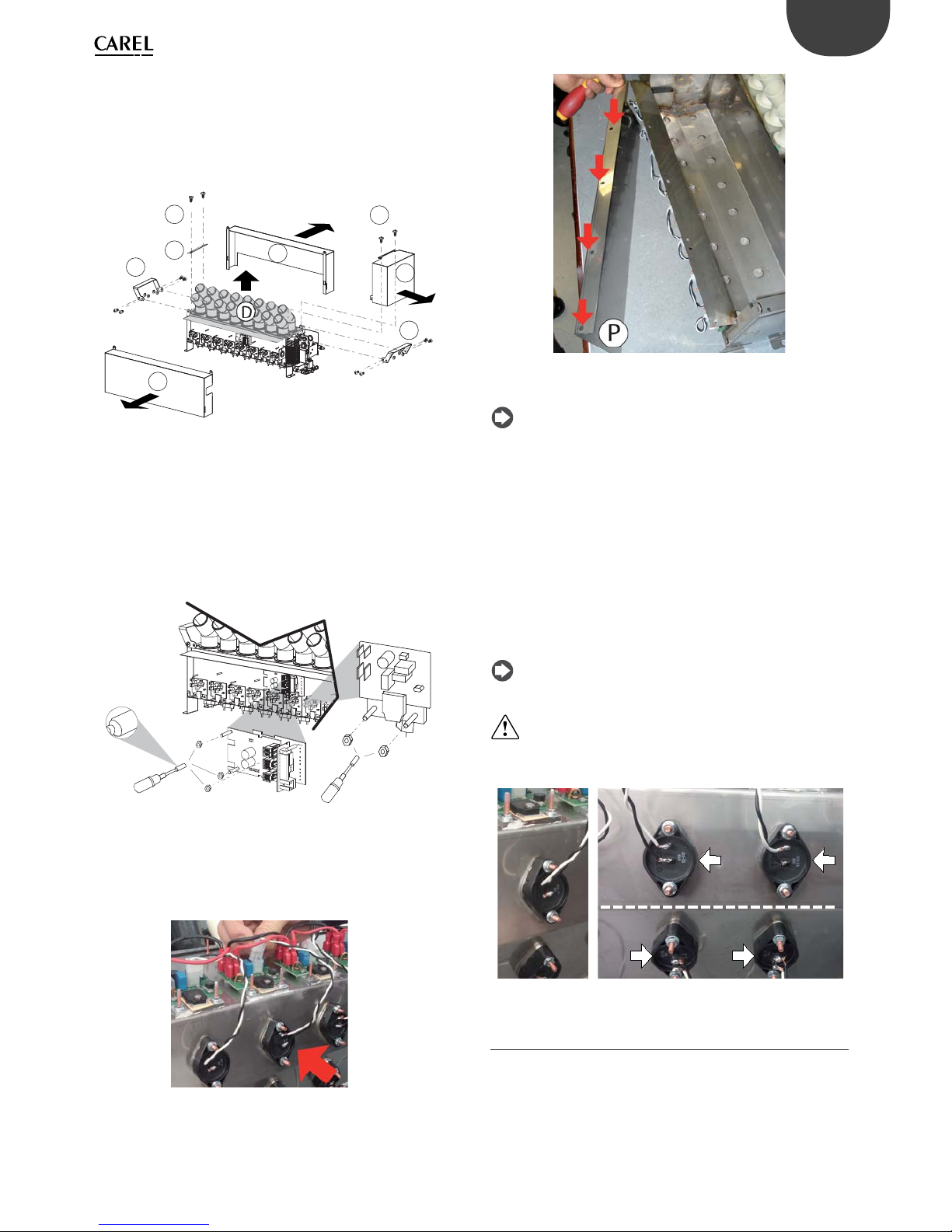
37
ENG
“humiSonic ventilation” +0300063EN - rel. 1.0 - 16.02.2016
Dismantling the panels (to access the front driver board and the tank)
After having removed the cover (C) on the terminal block, work on the
left-hand side and:
1. unscrew the screws (V ) that secure the bracket (S) and remove it;
2. loosen the bolts/nuts that fasten the handles (M) and remove them;
3. remove the front (G) and rear (H) panels;
4. fi nally, lift the cover (D) and the diff users to access the tank.
V
V
M
M
C
G
H
S
D
Fig. 10.g
Diff users
The diff users are only attached to the top cover. Once the cover has been
removed, to replace the diff users simply lift them off .
Control board and front driver board
Remove the front panel (G) as explained in the previous paragraph.
1. unplug the electrical cables connected to the controller board/driver
board;
2. loosen the fastening nuts and remove them with a socket wrench;
5
.
5
Fig. 10.h
Rear driver board
1. Unscrew the screws and remove the protective panel (P) to access the
rear driver board.
2. Remove the boards in the same way as described for the front driver
board.
Fig. 10.i
Fig. 10.j
Piezoelectric transducer
Note: the atomisation capacity of the piezoelectric transducer
gradually decreases with use. It must be replaced after around 10,000
operating hours (depending on water quality), even if the unit can
continue operating while eff ective capacity still responds to requirements.
To remove the piezoelectric transducer:
1. turn the humidifi er body over and identify the piezoelectric transducer
to be replaced;
2. unplug the electrical cable terminals from the corresponding driver
board;
3. using a socket wrench (5.5), loosen the fastening nuts, remove the
transducer and replace it;
4. when replacing the transducer, pay attention to the white markings
(arrow): the top line of transducers has the markings on the right, and
the bottom line has the markings on the left. The transducer must
have the markings positioned in the same ways as the adjacent ones.
Note: the tightening torque of the nuts that fasten the transducer
must be 4±0.5 kg cm
Important: if the transducer is fi tted rotated 180°; incorrect
assembly will cause a reduction in atomised water production and
potential humidifi er malfunctioning.
Fig. 10.k Fig. 10.l
10.8 Cleaning the tank
Proceed as shown previously to remove the side panels and top cover
with the diff users. To clean the tank, use a soft brush.
Page 38
38
ENG
“humiSonic ventilation” +0300063EN - rel. 1.0 - 16.02.2016
11. GENERAL FEATURES AND MODELS
11.1 Ultrasonic humidifi er models and
electrical specifi cations
The table below summarises the electrical data (power supply voltages)
of the various models, as well as their functional characteristics. Note
that some models can be powered at diff erent voltages, obviously with
diff erent current and atomised water production values.
Power supply
model Humidity production
(2,3)
(kg/h)
Power
(2)
(W)
Panel P/N * = B, D
(B = “Slave”, C = “Master”)
Voltage
(1)
(V – type) Current
(2)
(A) Vac
power supply
Current
(2)
(A) 48 Vdc
power supply
UU02D% 2.4 210 UQ05*D0000 230 0.7 3.2
210 UQ05*10000 110 1.5 3.2
UU05D% 4.8 350 UQ05*D0000 230 1.3 6.4
350 UQ05*10000 110 2.7 6.4
UU07D% 7.2 500 UQ09*D0000 230 2 9.6
500 UQ09*10000 110 4 9.6
UU09D% 9.6 650 UQ09*D0000 230 2.6 12.8
650 UQ09*10000 110 5.5 12.8
UU14D% 14.4 950 UQ18*D0000 230 4 19.2
950 UQ18*10000 110 8.2 19.2
UU18D% 18 1150 UQ18*D0000 230 4.7 24
1150 UQ18*10000 110 10 24
Tab. 11.a
(1) tolerance allowed on rated mains voltage: -15%, +10%;
(2) tolerance on rated values: +5%, -10% (EN 60335-1);
(3)
max rated instant atomised water production: average atomised water production may be aff ected by external factors, such as: ambient temperature, water
quality, distribution system.
Important: to avoid interference, keep power cables separate from probe cables.
11.2 Cable cross-section
See par. “Connection cable sizing: humidifi er – electrical panel”.
11.3 Technical specifi cations
Model UU02D% UU05D% UU07D% UU09D% UU14D%
UU18D%
Flow-rate l/h 2.4 4.8 7.2 9.6 14,4
18
No. of transducers 4 8 12 16 24
30
Rated power (W ) 180 330 480 600 1100
1100
Application duct
Feedwater pressure 1 to 6 bars
Feedwater temperature (°C) 5 to 40
Ingress protection IP20
Electronic controller
Auxiliary voltage / frequency (V/ Hz) 24V/50 – 60 Hz
Maximum auxiliary power (VA) 3
Probe inputs (general features) Can be selected for these signals: 0-1V, 0-5V, NTC low temperature: 10 kΩ at 25°C, -50T90 °C;
Power supply to active probes (general features) 21Vdc, max 150 mA
Relay outputs (general features for “Master” panel) EN60730-1: NA 1(1)A 250 Vac cos phi = 0.4; 100,000 cycles
UL-873: NO 1 A resistive 24 Vac, 30 Vdc, 100,000 cycles/PILOT DUTY: 24 Vac, peak 15A, continuous 1A
30,000 cycles
Alarm relay output (general features for “Slave” panel) 24 V (max 3 W)
Digital inputs (general features) Voltage-free contact. Max resistance 100 Ω; max 5 Vdc open, 7 mA closed
Analogue outputs (general features for “Master” panel) 0 to 10V Maximum load 2 kΩ (5 mA) Precision ±3 % of full scale
Environmental conditions
Ambient operating temperature °C (°F) 1 to 40 (33.8 to 104)
Ambient operating humidity (% rH) 10 to 60
Tab. 11.b
Page 39
39
ENG
“humiSonic ventilation” +0300063EN - rel. 1.0 - 16.02.2016
12. MULTIUNITS INSTALLATION
12.1 Connection master-slaves (until 4
humisonics)
In order to optimize the control and management of multiple humidifi ers
within the same conduct, it is possible to connect them in serial following
the diagrams reported below.
Setup
The “Master” unit is able to control the operation of a maximum of 3
“Slave“ units connected via tLan network. For electrical connections refer
to diagram in fi g.12.1.a and 12.1.b. The Master unit’s dipswitches 1-3 must
be all set to OFF. Each slave unit must be properly confi gured via the
following dipswitches:
1: Set to ON for the conversion of the serial port (M11) from 485 to tLan.
2/3: Slave address, as shown on page 2 (See Sect. 4 of Manual cod.
+0300056IT-EN).
Control logic
The Master unit controls each “Slave” unit, through the following
parameters:
• Enable / Disable the operation
• Level of production of atomized water
The control signals (probes / humidistat / external regulator) are read
and handled only by the Master who shall then adjust the operation of
the slave. The production level of the Master is replicated by all the Slave
units.
11.4 Fuse table
11.4.1 Electrical panel “Slave”
Electrical panel
P/N
48 Vdc power
supply fuse (one
10.3 x 38 fuse)
Power supply fuse
(two 5 x 20 fuses)
Fan fuse (one
5 x 20 fuse)
UQ05BD0000 8 A 2 A 250 mA
UQ05B10000 8 A 3.15 A 250 mA
UQ09BD0000 16 A 3.15 A 250 mA
UQ09B10000 16 A 6.3 A 250 mA
UQ18BD0000 30 A 5 A 250 mA
UQ18B10000 30 A 10 A 250 mA
Tab. 11.c
11.4.2 Electrical panel “Master”
Electrical panel
P/N
48 Vdc power
supply fuse (one
10.3 x 38 fuse)
Power supply fuse
(two 5 x 20 fuses)
Fan fuse (one 5
x 20 fuse)
UQ05CD0000 8 A 2 A 250 mA
UQ05C10000 8 A 3.15 A 250 mA
UQ09CD0000 16 A 3.15 A 250 mA
UQ09C10000 16 A 6.3 A 250 mA
UQ18CD0000 30 A 5 A 250 mA
UQ18C10000 30 A 10 A 250 mA
Tab. 11.d
Page 40
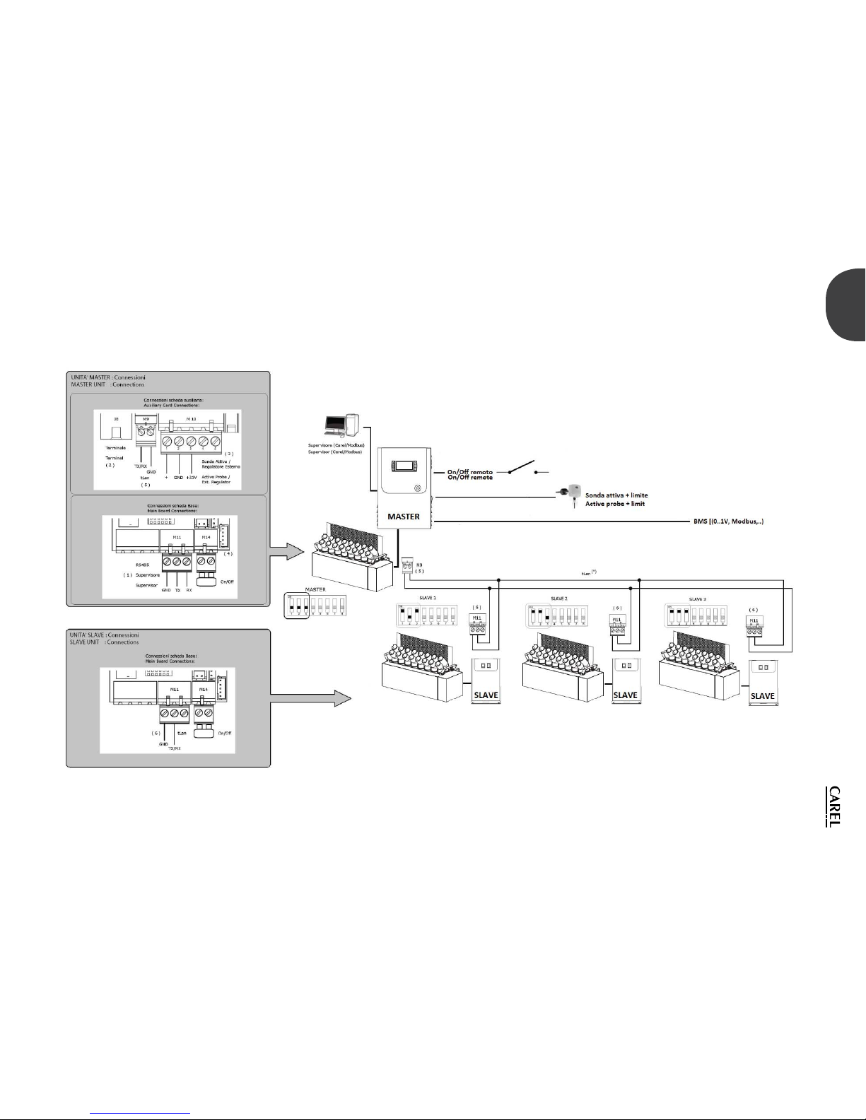
40
ENG
“humiSonic ventilation” +0300063EN - rel. 1.0 - 16.02.2016
Fig. 12.a
Page 41
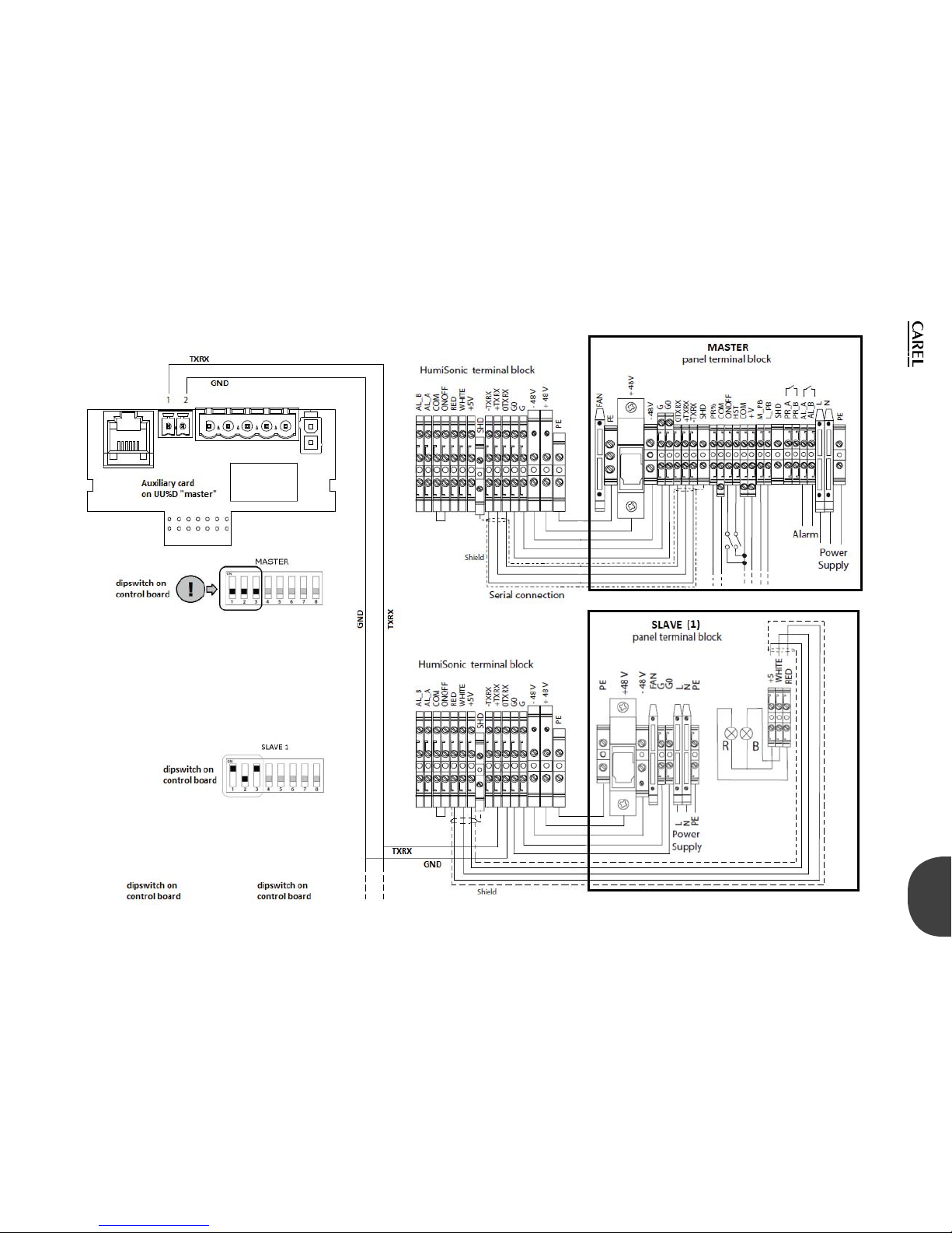
41
ENG
“humiSonic ventilation” +0300063EN - rel. 1.0 - 16.02.2016
Fig. 12.b
Page 42
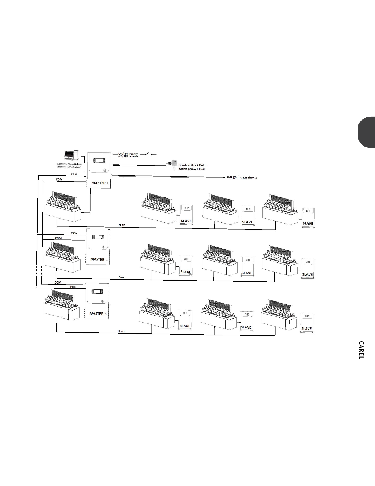
42
ENG
“humiSonic ventilation” +0300063EN - rel. 1.0 - 16.02.2016
12.2 Connection multi-master (until 4
masters)
When the units to be installed into the same duct are in a high number (5
to 24 units), it is appropriate to follow the diagram in Fig. 12.2.a and 12.2.b
Fig. 12.c
Page 43
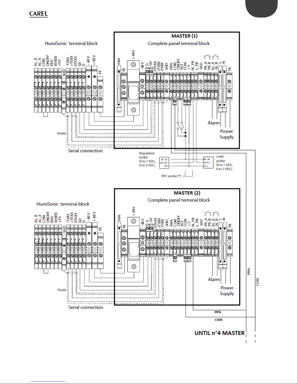
43
ENG
“humiSonic ventilation” +0300063EN - rel. 1.0 - 16.02.2016
Fig. 12.d
Page 44
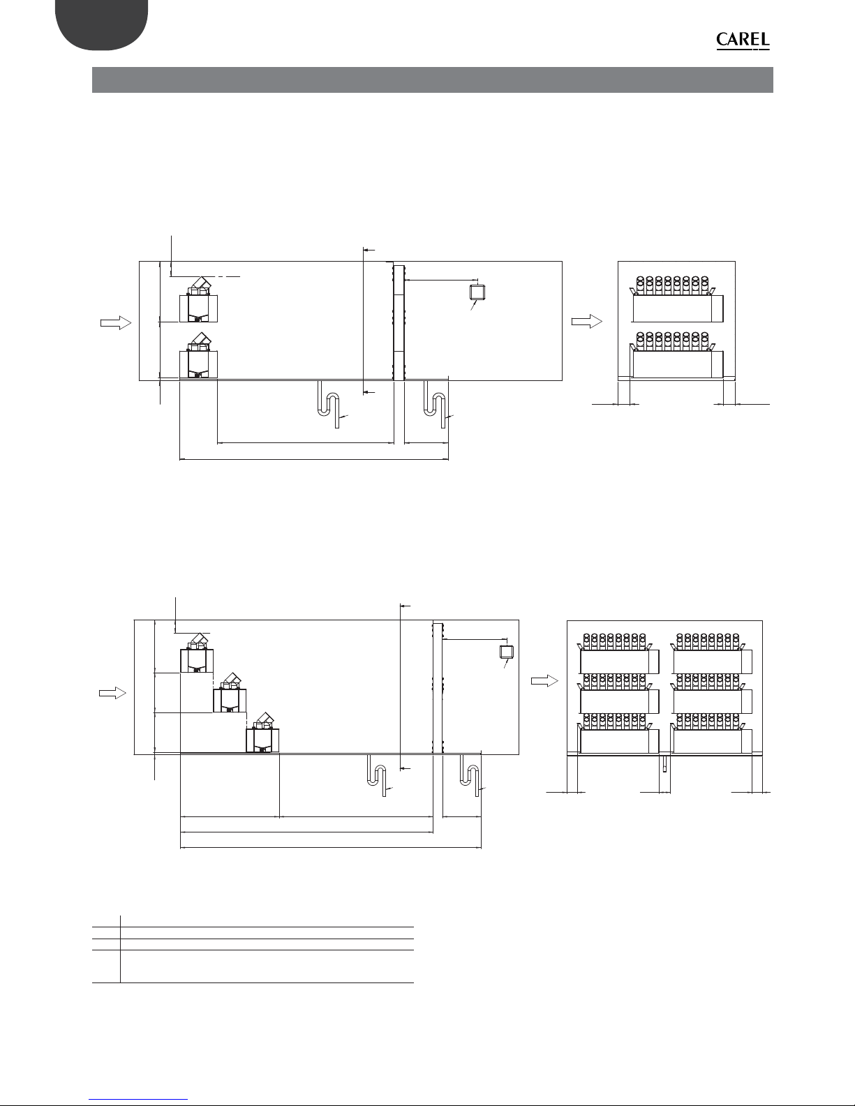
44
ENG
“humiSonic ventilation” +0300063EN - rel. 1.0 - 16.02.2016
13. DUCT INSTALLATION
If several Humisonics are to be installed into the same duct , it is necessary
to arrange them within the duct so as to obtain a homogeneous and
constant atomization.
Suggested installative layouts are:
• “On line” layout: units are positioned on diff erent levels along the same
vertical section. The diagram 13.1 shows the minimum distances for
humidifi ers placement within the same duct:
airflow
20
(0,8)
380
(14,96)
410
(16,14)
100
(3,94)
water drain basin
DL
drain
B
B
500
(19,69)
Limit probe
L_PB
airflow
300
(11,81)
drain
80
(3,15)
80
(3,15)
B-B
1:10
Fig. 13.a
• “Cascade” layout: unitsare positioned on diff erent levels and along
diff erent vertical sections. The diagram 13.2 shows the minimum
distances for humidifi ers placement within the same duct:
airflow
20
(0,8)
410
(16,14)
100
(3,94)
water drain basin
A
500
(19,69)
Limit probe
L_PB
airflow
300
(11,81)
drain
80
(3,1)
A-A
310
(12,20)
310
(12,20)
DL
DH
DT
A
drain
90
(3,5)
80
(3,1)
Fig. 13.b
Key:
DH
Humisonics total dimention
DL
Absorption distance
DT
Total length
For proper sizing and placement of Humisonic within the duct ,
contact Carel support
Page 45

Page 46

Page 47

Page 48

CAREL INDUSTRIES HQs
Via dell’Industria, 11 - 35020 Brugine - Padova (Italy)
Tel. (+39) 049.9716611 - Fax (+39) 049.9716600
e-mail: [email protected] - www.carel.com
Agenzia / Agency:
“humiSonic ventilation” +0300063EN - rel. 1.0 - 16.02.2016
 Loading...