

Page 1
heaterSteam - UR
electrical heater humidifi er
User manual
NO POWER
& SIGNAL
CABLES
READ CAREFULLY IN THE TEXT!
TOGETHER
Page 2

Page 3
IMPORTANT WARNINGS
BEFORE INSTALLING OR HANDLING THE AP PLIANCE PLEASE CAREFULLY READ AND FOLLOW THE
INSTRUCTIONS AND SAFETY STANDARDS DESCRIBED IN THIS MANUAL AND ILLUSTR ATED ON THE
LABELS ATTACHED TO THE MACHINE.
This humidifi er produces non-pressurised steam using heating elements immersed in the water contained in the cylinder (hereafter cylinder); the steam produced is used to humidify environments or
industrial processes, through special distributors.
The quality of the water used does not affect the evaporation process, and as a result the appliance can
be supplied with untreated water, as long as such water is fi t for drinking, demineralised or softened (see
Supply water characteristics); the evaporated water is automatically replaced using a refi ll valve.
To achieve uniform distribution of the heat fl ow, the heating elements, which are electrically insulated
from the water, are covered in an aluminium casting, and are also available with a special non-stick
coating to prevent and aid the removal of lime scale.
This appliance has been designed exclusively to directly humidify rooms or ducts, through distributors.
It has been developed for this purpose, as long as: the installation, use and maintenance of the unit are
carried out according to the instructions contained in this manual and on the labels applied, internally
and externally, to the unit.
The environmental conditions and the voltage of the power supply must correspond to those specifi ed.
All other uses and modifi cations made to the device that are not authorised by the manufacturer are
considered incorrect.
Liability for injury or damage caused by the incorrect use of the device lies exclusively with the user.
Please note that the machine contains powered electrical devices and hot surfaces.
All service and/or maintenance operations must be performed by specialist and qualifi ed personnel who
are aware of the necessary precautions.
Disconnect the machine from the mains power supply before accessing any internal parts.
The local safety standards in force must be applied in all cases.
ENGLISH
Disposal of the parts of the humidifi er: The humidifi er is made up of metallic and plastic parts.
In reference to European Community directive 2002/96/EC issued on 27 January 2003 and the related
national legislation, please note that:
1. We cannot be disposed of as municipal waste and such waste must be collected and disposed of
separately;
2. the public or private waste collection systems defi ned by local legislation must be used. In addition,
the equipment can be returned to the distributor at the end of its working life when buying new
equipment.
3. the equipment may contain hazardous substances: the improper use or incorrect disposal of such
may have negative effects on human health and on the environment;
4. the symbol (crossed-out wheeled bin) shown on the product or on the packaging and on the instruction sheet indicates that the equipment has been introduced onto the market after 13 August 2005
and that it must be disposed of separately;
5. in the event of illegal disposal of electrical and electronic waste, the penalties are specifi ed by local
waste disposal legislation.
Warranty on materials: 2 years (from the date of production).
Certifi cation: the quality and safety of CAREL products are guaranteed by CAREL’s ISO 9001 certifi ed
design and production system, as well as CE
or ETL mark.
The product must be installed with the earthconnected,
using the special yellow-green terminal on the terminal block. Do not use the neutral for the
earth connection.
NO POWER
& SIGNAL
CABLES
READ CAREFULLY IN THE TEXT!
TOGETHER
WARNING: separate as much as possible the probe and digital input signal cables from the cables carrying inductive
loads and power cables to avoid possible electromagnetic disturbance.
Never run power cables (including the electrical panel wiring) and signal cables in the same conduits.
heaterSteam +030222011 - rel. 2.1 - 21.05.2010
3
Page 4

ENGLISH
4
heaterSteam +030222011 - rel. 2.1 - 21.05.2010
Page 5

CONTENT
1. MODELS 7
1.1 Accessories .......................................................................................................................................................................................................................... 7
2. DESCRIPTION OF THE MAIN COMPONENTS AND FUNCTIONS 8
2.1 Level control ....................................................................................................................................................................................................................... 10
2.2 Overfi ll device .................................................................................................................................................................................................................... 10
2.3 Control of steam production .......................................................................................................................................................................................... 10
2.4 Measurement of supply water conductivity- alarm ...................................................................................................................................................10
2.5 Automatic draining ...........................................................................................................................................................................................................10
2.6 Foam elimination procedure .......................................................................................................................................................................................... 11
2.7 Safety thermostat (Motor Protector) ............................................................................................................................................................................ 11
2.8 Autotest procedure ........................................................................................................................................................................................................... 11
2.9 Measurement of the water temperature and pre-heating (not available in the version with type C control module) ............................ 11
2.10 Dehumidifi cation request signal (not available in the version with type C control module) ........................................................................ 11
2.11 Procedure for cleaning the drain valve (UR 2 to 10kg/h/4.4 to 22lbr/h) ............................................................................................................. 11
3. CONTROL PRINCIPLES 12
3.1 ON/OFF control (control module C) ............................................................................................................................................................................ 12
3.2 Modulating control (control module H) ...................................................................................................................................................................... 12
3.3 Setting the alarm thresholds (type H or T control module) ................................................................................................................................... 13
4. ASSEMBLY 14
4.1 Receipt and storage ........................................................................................................................................................................................................... 14
4.2 Dimensions and weights .................................................................................................................................................................................................14
4.3 Removing and replacing the front casing ...................................................................................................................................................................14
ENGLISH
5. POSITIONING THE UNIT 15
5.1 Fastening ............................................................................................................................................................................................................................. 15
6. WATER CONNECTIONS 16
6.1 Supply water characteristics ............................................................................................................................................................................................ 16
6.2 Characteristics of the drain water .................................................................................................................................................................................. 16
6.3 Technical specifi cations .................................................................................................................................................................................................. 17
6.4 Checks .................................................................................................................................................................................................................................17
7. ELECTRICAL CONNECTIONS 18
7.1 Power supply voltages .......................................................................................................................................................................................................18
7.2 Main control board ........................................................................................................................................................................................................... 19
7.3 Description of the terminal block and connections (functions and electrical specifi cations) ..........................................................................19
7.4 Auxiliary connections ........................................................................................................................................................................................................ 19
7.5 Other auxiliary contacts ..................................................................................................................................................................................................21
7.6 Checks ................................................................................................................................................................................................................................... 21
7.7 Wiring diagrams for the connection of the heating elements ................................................................................................................................ 22
7.8 Single-phase wiring diagram for 2-4kg/h (4.4-8.8lbr/h) humidifi ers with type C control module .......................................................................................... 23
7.9 Single-phase wiring diagram for 2-4kg/h (4.4-8.8lbr/h) humidifi ers with type H or T control module ........................................................ 24
7.10 Single-phase wiring diagram for 6kg/h (13.2lbr/h) humidifi ers with type C control module ........................................................................ 25
7.11 Single-phase wiring diagram for 6kg/h (13.2lbr/h) humidifi ers with type H or T control module ........................................................................................ 26
7.12 Three-phase wiring diagram for 6-10Kg/h (13.2-22lbr/h) humidifi ers with type C control module ..................................................................................... 27
7.13 Three-phase wiring diagram for humidifi ers with type H or T control module ................................................................................................28
7.14 Three–phase electrical diagram for 20 (44lbr/h) ( 208-230-400-460-5756V) 27-40Kg/h (59.5-88lbr/h) (400-460-575V)
humidifi ers with type C control module 400-460-575 V ................................................................................................................................................. 29
7.15 Three–phase electrical diagram for 20 (44lbr/h) ( 208-230-400-460-5756V) 27-40Kg/h (59.5-88lbr/h) (400-460-575V)
humidifi ers with type H control module 400-460-575 V .................................................................................................................................................30
7.16 Three–phase electrical diagram for 60Kg/h (132.2lbr/h) humidifi ers with type C control module 400-575 V ........................................31
7.17 Three–phase electrical diagram for 60Kg/h (132.2lbr/h)humidifi ers with type H control module 400-575 V .......................................... 32
7.18 Three–phase electrical diagram for 27Kg/h (59.5lbr/h)humidifi ers with type H control module at 208 - 230 V ..................................... 33
7.19 Three–phase electrical diagram for 27Kg/h (59.5lbr/h) humidifi ers with type H control module at 208 - 230 V.................................... 34
7.20 Three-phase electrical diagram for 60kg/h (132.2lbr/h) humidifi ers with type H control module at 460 V ............................................. 35
7.21 Three-phase electrical diagram for 60kg/h (132.2lbr/h) humidifi ers with type C control module at 460 V .............................................. 36
heaterSteam +030222011 - rel. 2.1 - 21.05.2010
5
Page 6

8. STEAM DISTRIBUTION 37
8.1 Ambient steam distribution: ventilated steam distributors ...................................................................................................................................... 37
8.2 Steam distribution in cold rooms ..................................................................................................................................................................................37
8.3 Ducted steam distribution: linear and concentrated jet distributors (OEM) ....................................................................................................... 38
8.4 Concentrated jet steam distribution (OEM) (only for humidifi ers up to 10 Kg/h/22 lbr/h) ...........................................................................39
8.5 Positioning linear distributors in the air duct .............................................................................................................................................................. 39
8.6 Installation of the steam pipe.........................................................................................................................................................................................40
8.7 Installing the condensate return pipe ..........................................................................................................................................................................40
8.8 Checks .................................................................................................................................................................................................................................40
9. START-UP 41
9.1 Preliminary checks ............................................................................................................................................................................................................ 41
9.2 Removing the heating element centring spring (only for three-phase models)................................................................................................41
9.3 Start-up ................................................................................................................................................................................................................................ 41
ENGLISH
10. THE HUMIDIFIER CONTROLLER 42
10.1 Type C control module, with indication LEDs and ON/OFF action ..................................................................................................................... 42
10.2 Type H or T control module, numeric LED display, modulating action ............................................................................................................. 43
11. READING AND PROGRAMMING THE PARAMETERS OF THE TYPE H OR T CONTROL MODULE 45
11.1 Reading and programming the set point ..................................................................................................................................................................45
11.2 Display of SW release ..................................................................................................................................................................................................... 45
11.3 Reading and programming the control parameters - reading the measurements ......................................................................................... 45
11.4 Reading and programming the confi guration parameters ................................................................................................................................... 46
11.4 Validity of the modifi cations to the parameters ......................................................................................................................................................49
11.5 Recalling the default parameters (factory settings) ................................................................................................................................................. 49
11.6 Resetting the hour counter .......................................................................................................................................................................................... 49
11.7 Displaying and modifying the unit of measure ....................................................................................................................................................... 49
11.8 Automatic total drain for inactivity...............................................................................................................................................................................50
11.9 User-adjustable duration of dilution drain ................................................................................................................................................................50
11.10 User-adjustable max. allowed no. of evaporation cycles between 2 dilution drains ..................................................................................... 50
11.11 Reduced fi lls to restore water level after evaporation ........................................................................................................................................... 51
11.12 P W M fi lls after dilution and high-level/foam drains .............................................................................................................................................. 51
12. THE REMOTE CONTROL (OPTIONAL ACCESSORY) 52
12.1 Description of the remote control ...............................................................................................................................................................................52
12.2 Programming from the remote control ..................................................................................................................................................................... 53
12.3 Exiting the programming phase .................................................................................................................................................................................. 54
13. SHUTTING DOWN THE UNIT 55
14. MAINTENANCE 56
14.1 Maintenance of the cylinder-cylinder ......................................................................................................................................................................... 56
15. ALARMS AND TROUBLESHOOTING 58
15.1 Alarm summary table .....................................................................................................................................................................................................58
15.2 Autotest Retry procedure (Fault tolerance) ............................................................................................................................................................. 60
15.3 Troubleshooting ............................................................................................................................................................................................................. 60
16. HUMIDIFIER TECHNICAL SPECIFICATIONS 61
17. SPARE PARTS 62
17.a Maintenance of the other plumbing components ................................................................................................................................................... 65
17.2 Replacing the components ............................................................................................................................................................................................ 66
17.3 Spare parts ........................................................................................................................................................................................................................ 68
17.4 Disposal of the parts of the humidifi er .......................................................................................................................................................................68
6
heaterSteam +030222011 - rel. 2.1 - 21.05.2010
Page 7
1. MODELS
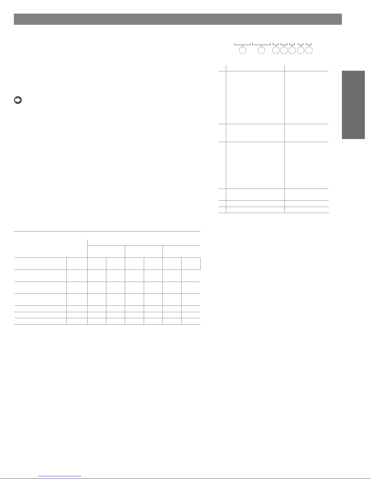
The code designating the model of electric heater humidifi er is made up of 10 characters, with the
following meaning (Fig. 1a).
Example: the code UR010CL101 identifi es an electric heater humidifi er (UR) with:
• rated steam production of 10kg/h
• ON/OFF control module (C);
• 400 Vac, three-phase power supply (L);
• full optional version (1).
NOTE: Not all the combinations are possible.
(22lbr/h) (010);
UR xxx x x x 0 *
1 2 3 4 5 6 7
1 ID prefi x;
2 rated instant steam production
in kg/h / lbr/h:
3 type of control: C= ON/OFF
4 type - power supply:
5 option: 0= base version
6 customisations
7 S for UR020
mod. production
002 2/4.4
004 4/8.8
006 6/13.2
010 10/22
020 20/44
027 27/59.5
040 40/88
060 60/132.2
H= modulating
T= for steam baths;
type V
U= 208 1~N
D= 230 1~N
W= 208 3~
K= 230 3~
L= 400 3~
M= 460 3~
N= 575 3~
1= full optional version
Fig. 1.a
ENGLISH
Table 1.a
1.1 Accessories
Table 1.b lists the accessories fi tted on the humidifi ers, in the various confi gurations.
type of control
C
(ON/OFF)
options 0: base 1: full
water temperature probe
and pre-heater
external thermal lining on
cylinder
elements coated with nonstick fi lm
lime collection fi lm * --- incl. --- incl. --- incl.
Remote control --- --- optional optional optional optional
Humivisor --- --- optional optional optional optional
*: not present on the full option version of the 20-27-40-60 kg/h (44-59.5-88-132.2 lbr/h) units;
---: not available;
incl.: accessory included.
optional
--- --- incl. incl. incl. incl.
--- incl. --- incl. --- incl.
--- incl. --- incl. --- incl.
H
(modulating)
0: base 1: full
optional
T
(for steam baths)
0: base 1: full
optional
Table 1.b
heaterSteam +030222011 - rel. 2.1 - 21.05.2010
7
Page 8
17
ENGLISH
16
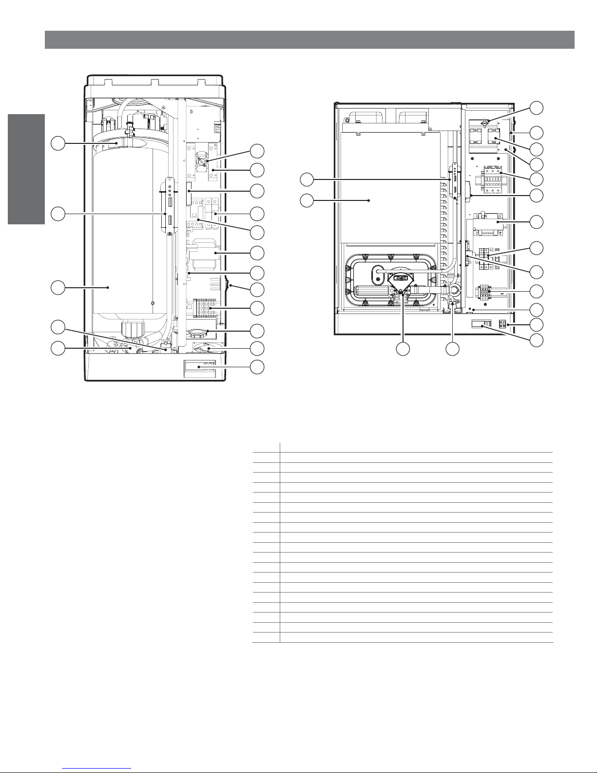
2. DESCRIPTION OF THE MAIN COMPONENTS AND FUNCTIONS
1
2
16
3
15
4
5
6
1
11
2
18
5
3
6
4
15
14
13
Fig. 2.a
7
8
9
10
11
12
Fig. 2.b
n. description
1 Klixon (motor overload – in models where featured)
2 Solid state relay (SSR) (in models where featured)
3 Motor protector
4 Fuse carrier base
5 Remote control switch
6 Transformer
7 Relay board
8 ON-OFF and manual drain switch
9 Power cable terminal block
10 Power cable gland
11 Fan (in models where featured)
12 Control module
13 Drain electrovalve
14 Fill electrovalve
15 Cylinder
16 Level controller
17 Locking lever
18 conveyor
19 drain pump
7
9
10
8
12
1419
Table 2.a
8
heaterSteam +030222011 - rel. 2.1 - 21.05.2010
Page 9
Humidifi ers up to 10 kg/h /22 lbr/h Humidifi ers from to 20-27-40-60 kg/h (44-59.5-88-132.2 lbr/h )
17
18
19
20
21
22
23
24
1516
Fig. 2.c
14
1213
28
11
10
9
8
27
7
6
5
ENGLISH
4
3
2
1
25 26
Fig. 2.d
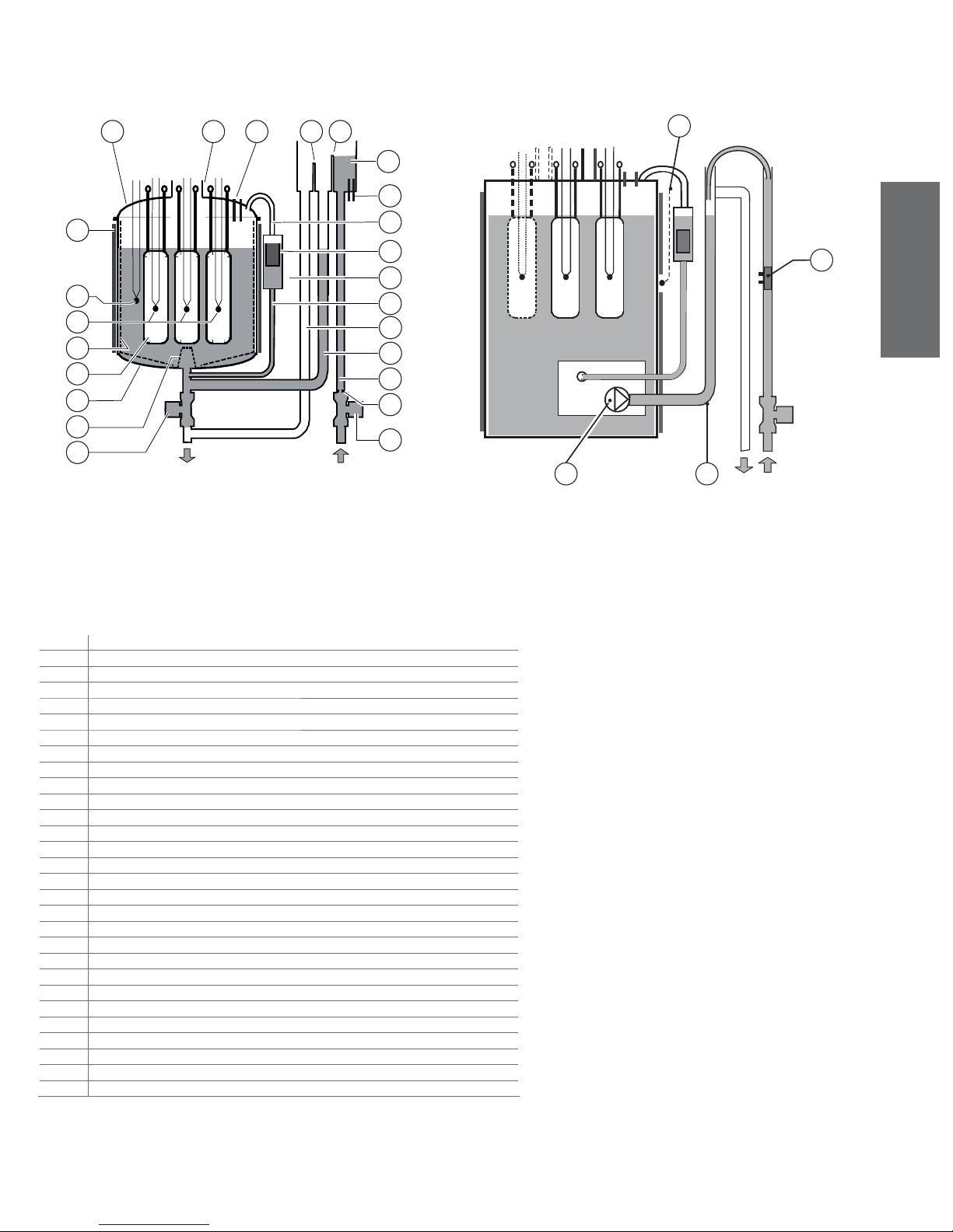
n. description
1 fi ll electrovalve
2 fl ow limiter
3 supply pipe
4 refi ll pipe
5 overfl ow pipe
6 connection pipe
7 level gauge housing
8 level control - level switch (following: level switch)
9 equaliser pipe
10 conductivity measurement electrodes
11 fi ll tank
12 fi ll diaphragm
13 overfi ll diaphragm
14 high level electrodes
15 steam outlet pipe
16 cylinder cover
17 thermal lining on the boiler (optional))
18 water temperature sensor (optional)
19 overheating sensors
20 lime collection fi lm
21 heating elements
22 cylinder housing
23 bottom fi lter
24 drain electrovalve
25 drain pump
26 Drain column
27 Conductivity meter
28 water temperature sensor (optional)
Table 2.b
heaterSteam +030222011 - rel. 2.1 - 21.05.2010
9
Page 10

2.1 Level control
Steam is produced with the heating elements completely immersed in water, whose level is controlled
by a sensor made up of two independent and overlapping fl oat switches, that is, the working level switch
and safety level switch.
2.1.1 L evel control
It is composed of a fl oat contained in a plastic pipe. Constrained to the level control case, an electronic
board detect the fl oat position and display the levels through three LEDs:
green working level, yellow charge level, red safety level. The signals, working and safety level, are
detailed in the paragraphs 2.1.2, 2.1.3.
2.1.2 Working level switch
This switch, which activates the fi ll electrovalve, introduces water through the special pipe into the fi ll
tank, from where, dropping from a fi ll diaphragm, it refi lls the level inside the cylinder; the fi ll electrovalve is fi tted with a fl ow limiter, maintaining the fl ow basically constant on changes in mains pressure.
ENGLISH
2.1.3 Safety level switch
This switch shuts off power to the elements, activating the alarm in the case where the level is insuffi cient.
2.2 Overfi ll device
This is a device used to avoid water exiting the cylinder over the safety level, due for example to the
malfunctioning of the control module (for more details, see THE HUMIDIFIER CONTROLLER) or to
leaking from the fi ll electrovalve.
The fi ll tank is fi tted with an overfi ll diaphragm which diverts the excess inlet water, discharging it
through special pipe.
The overfi ll diaphragm is lower than the fi ll diaphragm to avoid back fl ow through the supply pipe.
2.3 Control of steam production
Steam production can be controlled either:
• By step, alternating steam production with standby using a
humidistat or external contact; steam production can be controlled in four steps with pseudo-modulation from 30% to 100% of rated power, cyclically activating the remote-control switch (humidifi er
with type C control module).
• By continuous modulation from 0% to 100% of rated power, using solid-state relays (SSR); the
control logic is PWM (pulse width modulation) with programmable base times (humidifi er with type
H or T control module).
2.4 Measurement of supply water conductivity- alarm
To optimise the functionality of the humidifi er by suitably portioning the automatic draining cycles (see
Automatic draining), when the fi ll electrovalve is opened the conductivity of the inlet water is measured
using the special electrodes in the tank.
Two high conductivity thresholds can be set to activate respectively a pre-alarm and an alarm (with the
shut-down of the appliance) when these thresholds are exceeded for at least 60 minutes, or instantly if
the value measured is greater than three times the set value.
2.5 Automatic draining
The automatic draining function is managed by the control module. Part of the water contained in the
cylinder is drained automatically, being replaced by fresh water to prevent an excessive salt concentration following the evaporation process.
The drain pump/electrovalve is operated for a pre-set time at intervals that vary automatically as a
function of the steam production and the content of solids dissolved in the supply water, detected using
the conductivity measuring electrodes.
Irrespective of the concentration of salt in the supply water, at least one drain cycle is performed within
a maximum interval based on the quantity of steam produced; this is also true for demineralised supply
water.
10
heaterSteam +030222011 - rel. 2.1 - 21.05.2010
Page 11

2.6 Foam elimination procedure
The level of water inside the cylinder is maintained by the level control at around 10-12 cm / 3.94-4- .72inch
(about 18-20 cm /7.1-7.87inch for the cylinder of the 20-60 kg/h/44-132.2lbr/h humidifi ers) from the
top of the cylinder, therefore, when the high level electrodes are wet, an anomalous situation arises,
generally caused by the presence of foam. In this case a drain procedure is activated, and is repeated
until the phenomenon desists or, in the event of multiple activation, until the appliance is shut-down and
an alarm state is signalled.
2.7 Safety thermostat (Motor Protector)
The mechanical safety thermostat with manual reset intervenes in the event of overheating, caused by a
lack of water inside the cylinder due to the malfunctioning of the minimum level control. This deactivates
the relay that controls the power supplied to the elements, and places the humidifi er in an alarm state.
2.8 Autotest procedure
Each time the humidifi er is started (switched from the OFF to the ON position), an autotest (default)
procedure is performed, including checks on the operation of the level control, to test the regular
functioning of the appliance:
1. “At” is shown during the autotest;
2. The autotest can be temporarily manually disabled by pressing key SEL during the initial 5 seconds
after switching on heaterSteam: “-nt” will be shown. Note that this procedure disables the autotest
only for the switch-on in course, not permanently (read below for disabling the autotest
permanently);
3. The autotest can be disabled permanently by setting the parameter b1 as shown in table in
chapter 11.4.
On start-up and on each draining cycle the operation of the level control is automatically checked by
opening the fi ll electrovalve until the activation of the working level switch (green LED) and, successively,
opening the drain pump electrovalve until the activation of both level switches, and fi nally, restoring
the correct level, NOTE: returns to the working level only if there is demand, otherwise remains at the
safety level; in the event of a failed test or irregular timing the remote-control switch is automatically
deactivated and the alarm activated.
2.9 Measurement of the water temperature and pre-heating
(not available in the version with type C control module)
The control module measures, using an NTC sensor, the temperature of the water, and can be programmed to activate the pre-heating function near the value set for the start of humidifi cation; in this way,
steam production occurs more quickly.
ENGLISH
2.10 Dehumidifi cation request signal (not available in the
version with type C control module)
If activated, this function closes the relay contact when the relative humidity measured by the transducer
connected to the control module exceeds the set threshold.
This signal can be used to activate an external dehumidifi cation device.
2.11 Procedure for cleaning the drain valve (UR 2 to 10kg/h/4.4
to 22lbr/h)
For the models with drain valve there are two procedures used to clean the drain valve.
The purpose is:
1. to prevent the valve from being blocked due to fl akes of lime scale.
2. to prevent the solenoid drain valve from leaking.
• The fi rst procedure is activated during a drain to dilute (automatic draining, see par. 2.5), drain due to
foam or due to inactivity cycle. This procedure is used to repeatedly activate and deactivate (with the fi ll
valve open) the drain valve for 1 second at start of the drain cycles.
• The second procedure, called “chattering”, is activated when fi lling the water in steady operation, and
involves repeatedly activating and deactivating the drain valve for 1 second when the algorithm
calculates that a no water alarm condition (“EF”) is about to occur.
heaterSteam +030222011 - rel. 2.1 - 21.05.2010
11
Page 12
ENGLISH
Pmax
Pmin
3. CONTROL PRINCIPLES
The range of humidifi ers includes the following control possibilities.
3.1 ON/OFF control (control module C)
The action in this case is all or nothing, activated by an external contact that determines the set point and
the control differential (or hysteresis).
Average steam production can be adjusted using a pseudo-modulating action, through the cyclical activation of the remote-control switch with a fractional actuation period (operation) that can be programmed in four steps: 30%, 50%, 75% or 100% of the total time (this mode can not be applied in severe
operating conditions and without consequences on the noise level, caused by the frequent activation of
the remote-control switch).
3.2 Modulating control (control module H)
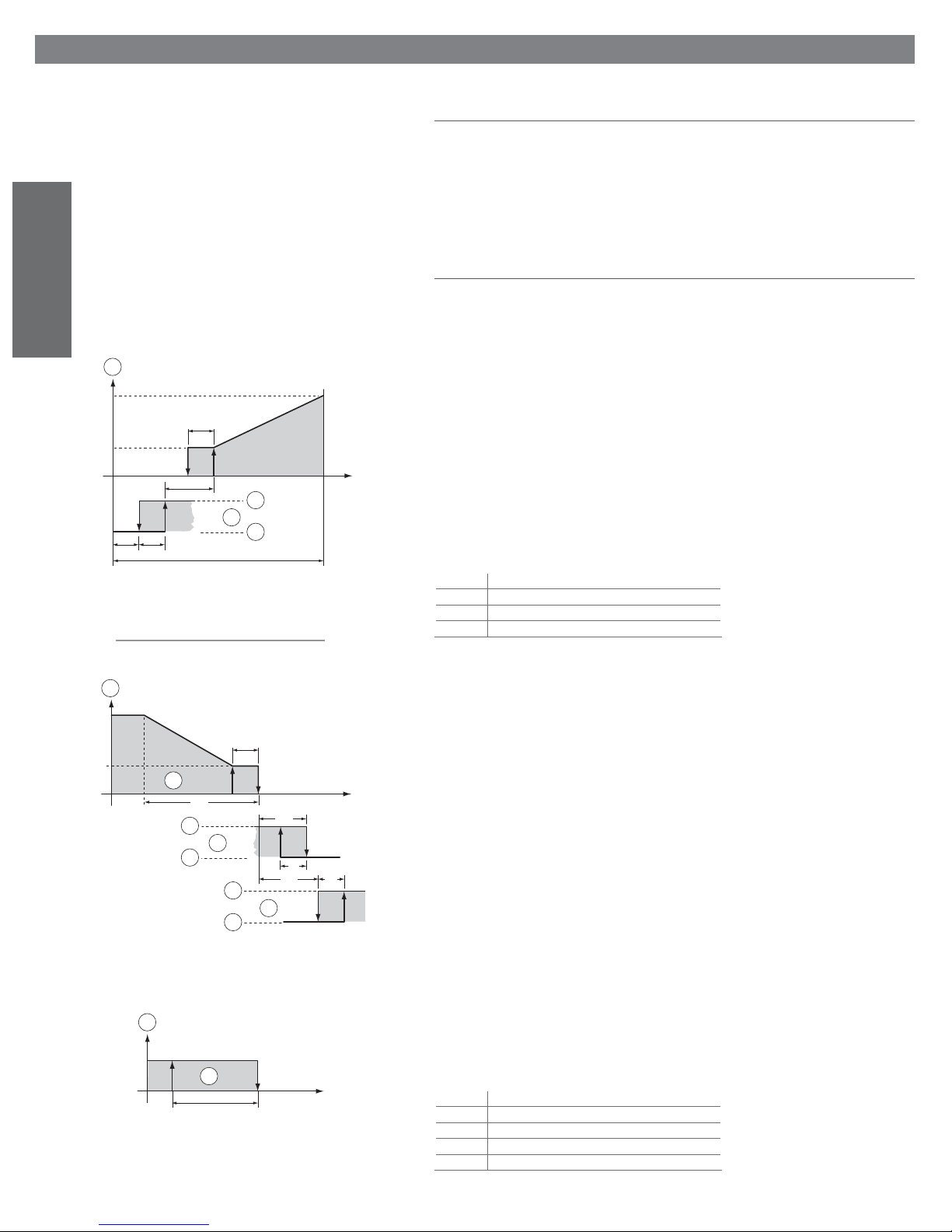
The appliance is fi tted with solid-state relays and steam production can be controlled continuously as a
function of the required quantity, in one of the following modes.
3.2.1 ON/OFF control (parameter A0=0)
1
hy
OFF
ONOFF
b2
ON
hy
hyhy
3
2
4
BP
Y
1 Vdc
10 Vdc
10 Vdc
20 mA
20 mA
Fig. 3.a
As for the type C control module (see ON/OFF control (type C control module)).
3.2.2 Slave control, with signal emitted from an external regulator (parameter A0= 1)
Steam production is proportional to the value of an external signal Y, (selected by programming one of
the following standards: 0 to 1Vdc; 0 to 10Vdc; 2 to 10Vdc; 0 to 20mA; 4 to 20mA) the entire range of
which is indicated by BP (proportional band).
The maximum production Pmax, corresponding to the maximum value of the external signal Y, can be
programmed between 10% and 100% of the rated value of the humidifi er.
The minimum production Pmin is fi xed at 10% of the rated value, with an
activation hysteresis provided by the value hy, equal to 2% of the entire range BP of the external signal Y.
If enabled, the pre-heating function overlaps the control diagram, and is activated when the external
signal Y is lower than the activation point for steam production by a quantity b2.
Key
1 steam production;
2 pre-heating;
3 activated
4 deativated
Pmin
1
P0
hy
3.2.3 Autonomous control with relative humidity transducer (parameter A0= 2)
Steam production is linked to the measurement of % rH, performed by the relative humidity transducer
connected to the regulator, and increases as the distance from the set point St increases.
P1
3
4
ON OFF
ST
2
3
4
% rH
b2
OFFON
hy
P5
P6
OFF
5
ON
The maximum production P0, which occurs when the relative humidity is less that the set point by a
value P1, can be programmed between 10% and 100% of the rated value of the humidifi er.
The minimum production Pmin is fi xed at 10% of the rated value, with an activation hysteresis provided
by the value hy, equal to 10% of P1.
The pre-heating function, if enabled, overlaps the control diagram and is activated when the relative
humidity % rH, measured by the transducer, is higher than St by a programmable quantity b2.
The dehumidifi cation function, if enabled, overlaps the control diagram and is activated when the relative
humidity % rH, transmitted by the transducer, is higher than St by a programmable quantity P5+P6; the
hysteresis of the step, also programmable, is equal to P6.
1
To check that the relative humidity measured by the transducer is within the pre-set values, the control
Fig. 3.b
module with autonomous control allows two alarm thresholds to be programmed:
• high relative humidity alarm threshold P2;
• low relative humidity alarm threshold P3.
When these thresholds are exceeded, after a programmable delay P4, an alarm state is activated, with
1
Pnom
ON OFF
1
P1
Fig. 3.c
% rH
St
the closing of the contact of the corresponding relay on the main control board.
With autonomous control (parameter A0=2) it is also possible to have an ON/OFF action, as represented
in the graph, by disabling power modulation (setting parameter b0=0).
The pre-heating and/or dehumidifi cation, if enabled, remain unchanged.
Key
1 steam production;
2 pre-heating;
3 activated
4 deativated
5 dehumidifi cation
12
heaterSteam +030222011 - rel. 2.1 - 21.05.2010
Page 13
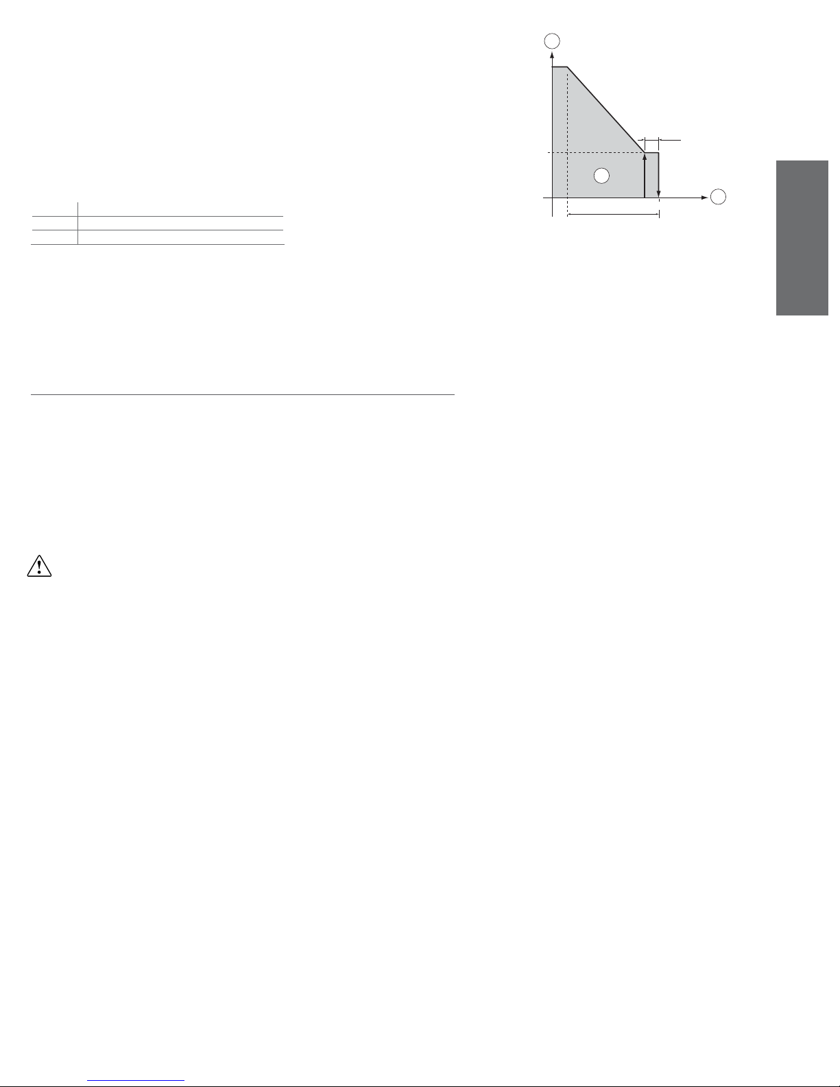
3.2.4 Autonomous control with ambient relative humidity transducer and outlet humidity
limiting transducer (parameter A0= 3)
In this case too the regulator modulates steam production as a function of the measurement % rH performed by the main relative humidity transducer, however, in addition, its entity is limited if the relative
humidity % rH2 measured by a second compensation transducer placed in the air duct downstream
from the humidifi er exceeds the maximum desired value.
To prevent the relative humidity measured by the transducer in the air duct downstream from the
humidifi er exceeding a value considered as excessive, the control module with autonomous control
and second transducer connected allows a high outlet relative humidity alarm threshold P9, to be programmed. If this threshold is exceeded, after a programmable delay P4, an alarm state is activated, with
closing of the contact of the corresponding relay on the main control board.
Key
1 production limit %
2 steam production
3 limit probe (% rH2)
Pmin
1
P0
10% P8
ON OFF
2
P8
P7
3
Fig. 3.d
3.2.5 Application for steam baths (type T control module)
In applications for steam baths, where the control probe measures temperature rather than humidity, the
same considerations are valid as for the type H control module with modulating action and autonomous
control.
Recommended transducer: SSTOOB/P40, ASET030001 or ASET030000.
3.3 Setting the alarm thresholds (type H or T control module)
The control module panel allows the setting of limit thresholds for the activation of the alarm in the
event where these are exceeded.
These alarm thresholds can be programmed using the following control parameters:
• P2: high relative humidity alarm threshold, measured by the room probe;
• P3: low relative humidity alarm threshold, measured by the room probe;
• P4: alarm signalling delay (to prevent false signals);
• P9: high relative humidity alarm threshold, measured by the outlet probe (for ducted humidifi cation).
Parameters P2, P3, P4 are programmable only when A0=2 or 3; parameter P9 is programmable only
when A0=3.
Furthermore, the control module can signal the excessive conductivity (and salt concentration) of the
supply water, but only as a default setting.
WARNING: the parameter A0 and the operating and alarm parameters Px and b0 are set in the factory
(default values valid for normal applications). Nonetheless, these can be modifi ed by the user, following
the instructions contained in: Reading and programming the parameters for the type H or T control
module.
ENGLISH
heaterSteam +030222011 - rel. 2.1 - 21.05.2010
13
Page 14
ENGLISH
4. ASSEMBLY
4.1 Receipt and storage
Check that the humidifi er is intact upon receipt and immediately notify the shipping agent, in writing, of
any damage that may be due to improper or careless transport. Move the humidifi er to the place of
installation before removing it from the packaging, grasping the neck only from below the base. Open
and remove the box, remove the layer of protective material and move the humidifi er from the pallet to
the support surface, keeping it vertical at all times; only remove the protective bag when installing the
unit.
4.2 Dimensions and weights
A
C
B
Fig. 4.a
references UR002 UR004 UR006 UR010 UR020 UR027 UR040 UR060
dimensions
(mm) / (inch)
weights (kg)/
(libre)
A 365 /
14.37
B 275 /
10.83
C 620 /
24.41
packaged 26 /
57.2
empty 21 /
46.2
installed * 27 /
59.4
*: in operating conditions, fi lled with water
365 /
365 /
14.37
14.37
275 /
275 /
10.83
10.83
620 /
710 /
24.41
27.95
26 /
31/
57.2
68.2
21 /
26 /
46.2
57.2
27 /
35 / 77 35 / 77 97 /
59.4
365 /
14.37
275 /
10.83
710 /
27.95
31/
68.2
26 /
57.2
models
690 /
27.17
438 /
17.24
887 /
34.92
73 /
160.6
63 /
138.6
213.4
690 /
27.17
438 /
17.24
887 /
34.92
73 /
160.6
63 /
138.6
97 /
213.4
690 /
27.17
438 /
17.24
887 /
34.92
77 /
169.4
67 /
147.4
114 /
250.8
876 /
34.49
438 /
17.24
887 /
34.92
98 /
215.6
87 /
191.4
155 /
341
Table 4.a
2
1
4
Fig. 4.b
Fig. 4.c
3
handle
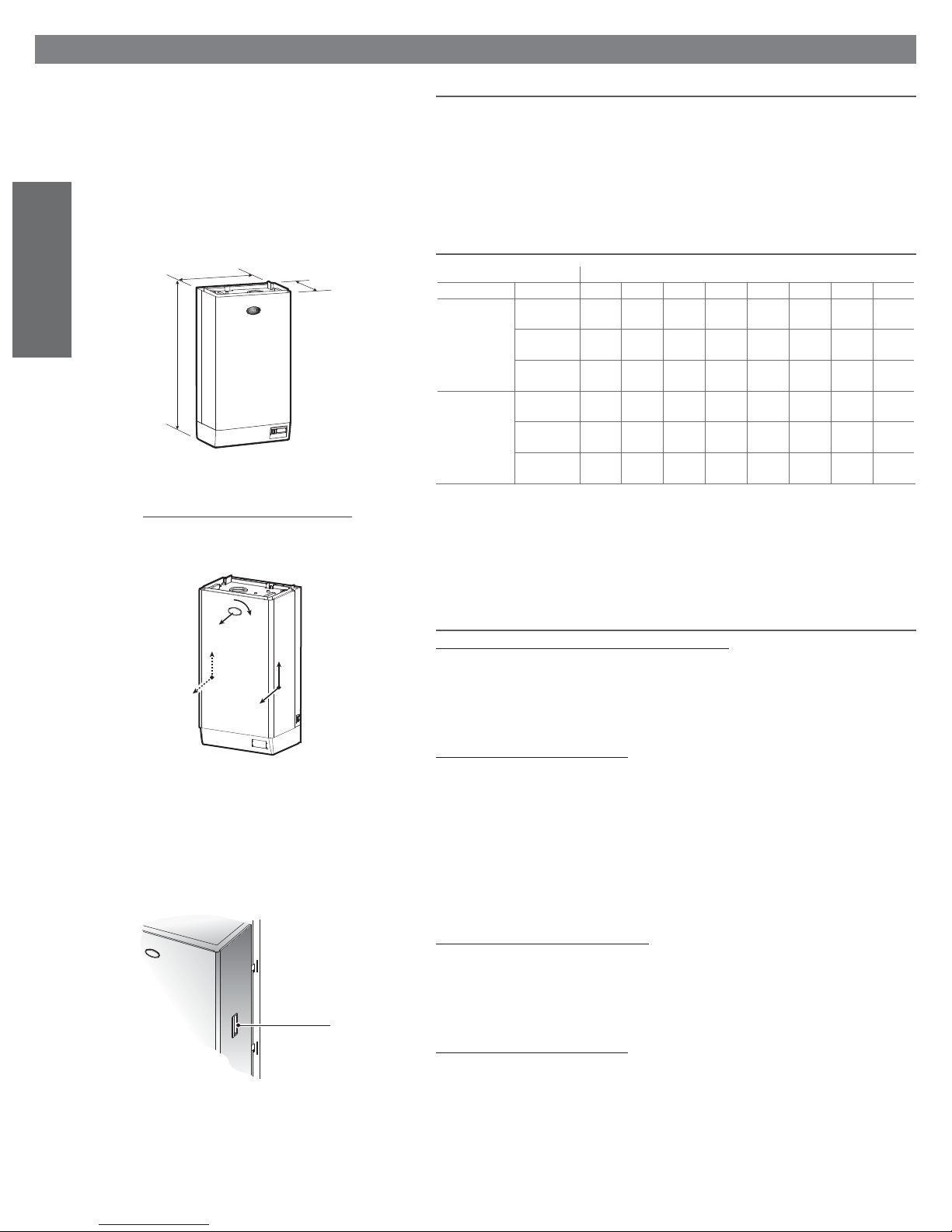
4.3 Removing and replacing the front casing
To remove the front casing of the humidifi er, proceed as follows:
1. turn the oval badge with the CAREL logo 90°, until the ground screw below can be seen;
2. remove the screw, using a screwdriver;
3. grip the casing by the sides and lift it around 2 centimetres, releasing the contours from the
raised edges on the cover and the base of the structure;
4. remove the casing by pulling it forward.
To close the appliance, proceed as follows:
1. turn the red oval plate with the CAREL logo so that the fastening hole below is visible;
2. slide the casing onto the structure, keeping it in a slightly raised position, until it rests on the edges
of the rear piece; then move it downwards slotting the upper and lower contours into the edges of
the cover and the base of the structure respectively; check that the fastening hole below the logo is
in line with the threaded bush attached to the structure;
3. fasten the ground screw using a screwdriver;
4. place (rotate) the oval plate with the CAREL logo in the closed position.
For 20-60 kg/h/44.1 - 132.2 lbr/h humidifi ers
To remove the front casing, proceed as follows:
1. turn the oval badge with the CAREL logo 90°, until the ground screw below can be seen;
2. remove the screw, using a screwdriver;
3. grip the casing by the sides using the handles, and lift it so that the hooks on the sides are released
from the structure;
4. remove the casing by pulling it forward.
To close the appliance, proceed as follows:
1. turn the red oval plate with the CAREL logo so that the fastening hole below is visible;
2. slide the casing onto the structure, keeping it in a slightly raised position, until the hooks fi t into the
structure; check that the fastening hole below the logo is in line with the threaded bush
attached to the structure;
3. fasten the ground screw using a screwdriver;
place (rotate) the oval plate with the CAREL logo in the closed position.
14
heaterSteam +030222011 - rel. 2.1 - 21.05.2010
Page 15
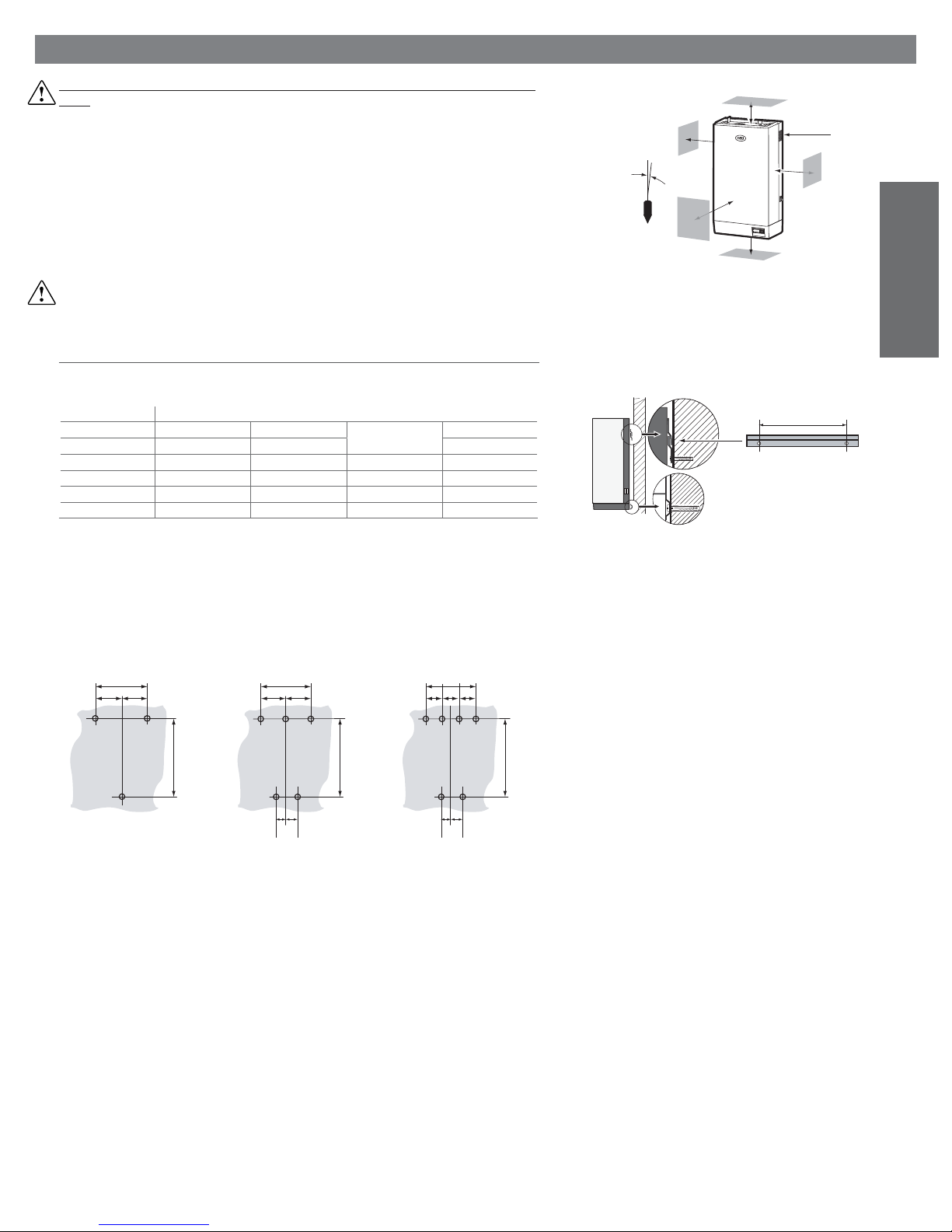
5. POSITIONING THE UNIT
The humidifi er must be positioned and fastened by qualifi ed personnel, following the instructions listed
herein.
Choose the best location for the installation of the steam distributor, that is the position which minimises
the length of the steam pipe or, in the case of direct ambient humidifi cation using a ventilated distributor, the central point of the space being humidifi ed (see STEAM DISTRIBUTION). The unit is designed to
be mounted to a wall that must be able to support its weight in operating conditions (see Dimensions
and weights).
The metal casing of the humidifi er heats up during operation, and the rear part resting against the wall
may reach temperatures above 60 °C / 140 °fH; ensure that this does not cause any problems. Make
sure the machine is level, respecting the minimum distances indicated in the drawing, to allow the
necessary maintenance operations.
WARNING: ensure that the cooling fan outlet grille is not blocked or covered.
5.1 Fastening
The appliance must be fastened to the wall using the supplied screws and plugs.
Use the following distances for the drilling template.
models
X (mm) / (inch) 220 / 8.66 220 / 8.66 495 / 19.48 681 / 26.81
Y (mm) / (inch) 500 / 19.68 590 / 23.23 740 / 29.13 740 / 29.13
Z (mm) / (inch) - - 155 / 6.10 248 / 9.76
Z’ (mm) / (inch) - - 155 / 6.10 248 / 9.76
Fasten the bracket supplied with the humidifi er to the wall, checking that it is horizontal using a spirit
level; if it is mounted to a brick wall, the plastic wall plugs (Ø 8 mm)/(Ø 0.31 inch) and screws (Ø 5 mm
x L= 50 mm)/(Ø 0.2 inch x L=1.97 mm) supplied can be used.
UR002 UR006 UR020-UR027 UR060
UR004 UR010 UR040
Table 5.a
<0,5o
r300
r200
griglia
r200
r700
r400
Fig. 5.a
ENGLISH
X
bracket
Fig. 5.b
UR 2-10 kg UR 20-27-40 kg UR 60 kg
X
=
=
Y
X
==
ZZ'
X
= = =
Y
ZZ'
Y
Fig. 5.c
Hang the appliance on the bracket using the contour on the upper edge of the rear of the unit.
Finally, fasten the appliance to the wall using the hole in the centre rear of the base. This can be easily
reached from the bottom.
heaterSteam +030222011 - rel. 2.1 - 21.05.2010
15
Page 16
6. WATER CONNECTIONS
The water connections for the supply and the draining of the unit must be made by specialist and
qualifi ed personnel, who are capable of performing the work correctly and according to local standards.
Before making the connections, ensure that the machine is disconnected from the mains power.
6.1 Supply water characteristics
The supply water for the electric heater humidifi er must not be corrosive, must not emit bad odours, and
must not contain too much lime to avoid excessive deposits.
The water, supplied from mains drinking water or demineralised water, must have the following
characteristics:
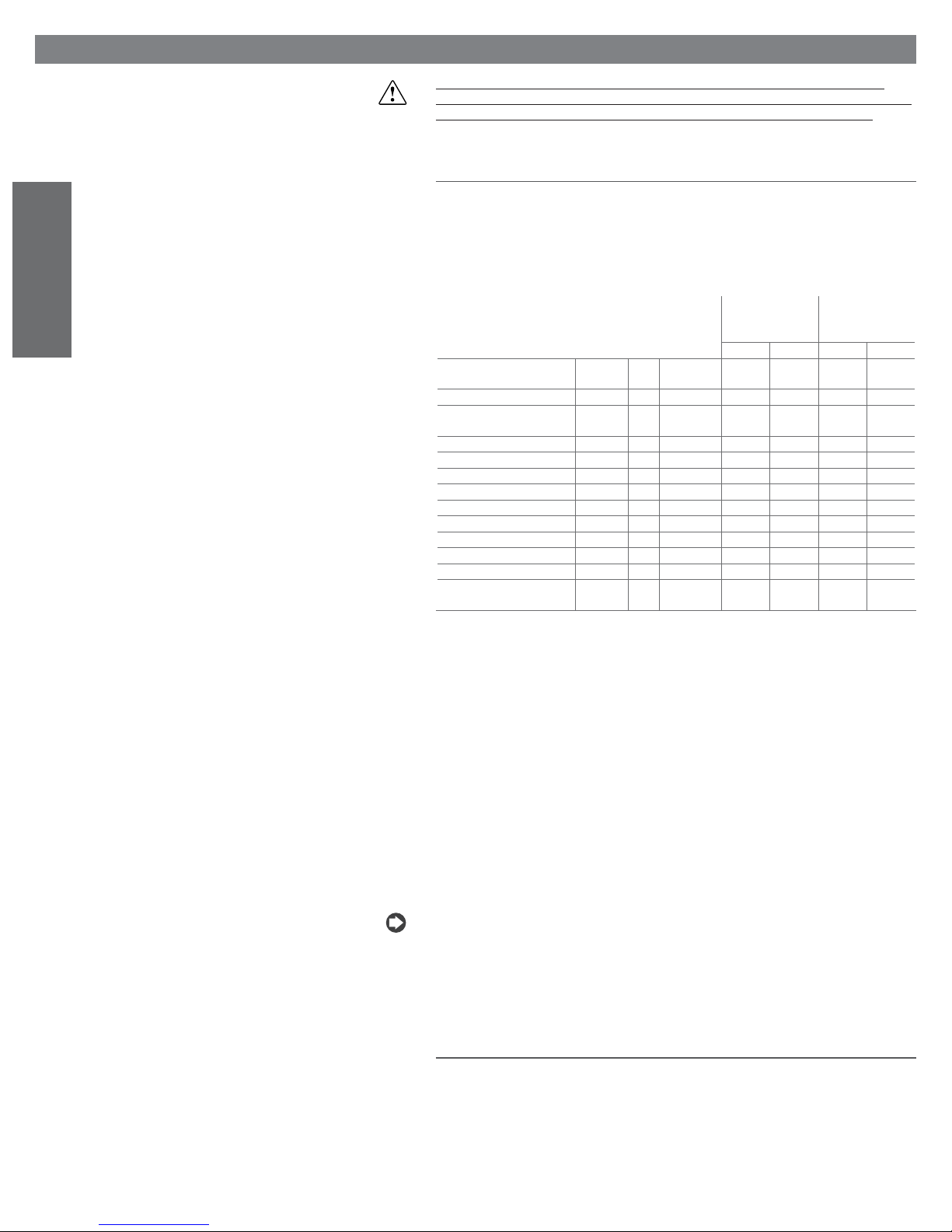
LIMIT VALUES FOR THE HUMIDIFIERS SUPPLY WATER TO HEATING ELEMENTS
ENGLISH
Not covered hea-
ting elements
Heating elements
covered by the
antiadherent fi lm
min. max. min. max.
Specifi c conductivity at 20°C
/68°fH
Total dissolved solids TDS - mg/l
Fixed residual at 180°C/
356°fH
Hydrogenion activity 6.1.1 pH - 6, 5 8 6 8.5
Total hardness TH - mg/l CaCO3 0 (2) 400 0 400
Temporary hardness - mg/l CaCO3 0 (3) 30 0 300
Chloride - ppm Cl = 20 = 50 (4)
Iron + Manganese - mg/l Fe+Mn = 0.2 = 0.2
Silica - mg/l SiO2 =20=20
Residual Chlorine - mg/l Cl - = 0.2 = 0.2
Calcium sulphate - mg/l CaSO4 =100=100
Metallic impurities - mg/l 0000
Solvents, diluents, detergents,
lubricants
20 - µS/cm 20 1500 1 1500
(1) (1) (1) (1)
R180 - mg/l
- mg/l 0000
(1) (1) (1) (1)
Table 6.a
(1) Values depending on the specifi c conductivity; in general: TDS 0,93 *
(2) Not lower than 200% the content of chloride in mg/l Cl-
(3)
Not lower than 300% the content of chloride in mg/l Cl-
(4)
It could be necessary to intervene on the drain rate to avoid a concentration in the water higher than 300
mg/l Cl-.
R, 20 °C; R180
0,65 *
R, 20 °C
;
Note that treating the water with softeners or polyphosphates does not decrease the quantity of
dissolved salts, and can lead to the formation of foam and hence irregular operation and corrosion of
heating elements.
If softened water is used, it should be diluted with mains tap water in such proportions as to ensure a
minimum hardness of 5° fH, and parameter b4 should be set (value 1500) so as to increase the frequency of the drain cycles for dilution.
Not recommended:
1. the use of well water, industrial water or water from cooling circuits and, in general, water which
may be chemically or bacteriologically contaminated;
2. the addition to the water of disinfectants or anticorrosion compounds, as these may cause irritation.
Nota: no relationship can be proven between water hardness and conductivity; nonetheless, as an
indication only, water with a hardness of 40°fH should have an approximate conductivity of around
900-1000 mS/cm at 20 °C/68°fH.
6.2 Characteristics of the drain water
Inside the humidifi er water boils and steam is produced, without the addition of any kind of substance.
The drain water, therefore, contains the same substances as those dissolved in the supply water, yet
in a greater proportion, depending on the concentration in the supply water and the set drain cycles;
it can also reach a temperature of 100 °C
collection system. The drain pipe, as well as being resistant to high temperatures, must also guarantee
the correct downfl ow of the water; a downward slope of at least 5° is therefore recommended.
16
/212°fH. Not being toxic, it can be drained into the backwater
heaterSteam +030222011 - rel. 2.1 - 21.05.2010
Page 17
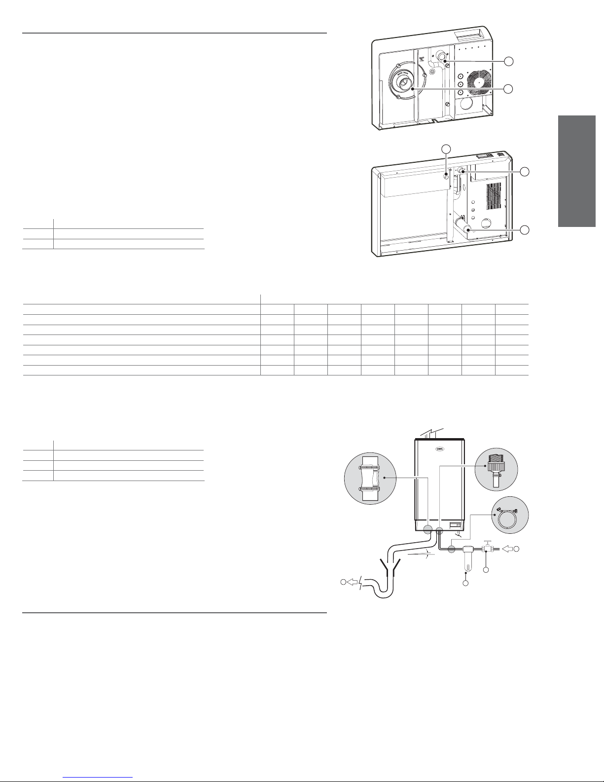
6.3 Technical specifi cations
UR 2-10 kg/h
The installation of the humidifi er requires connection to the supply water and drain pipe.
The connection of the supply water can be made using rigid or fl exible pipes with a minimum recommended internal diameter of 6mm, fi tted with a shut-off tap to allow the appliance to be disconnected
1
during maintenance operations. To simplify installation it is recommended to use CAREL fl exible pipes
with an internal diameter of 6 mm and an external diameter of 8mm (code 1312350APN) and the
rotating 3/4”G straight (code 9995727ACA) or elbow connector (code 9995728ACA), available upon
2
request.
It is recommended to install a mechanical fi lter to trap any solid impurities.
The drain water connection is made using a section of rubber or plastic pipe resistant to temperatures of
100°C/212°fH, with a recommended internal diameter of 36 mm/1.42inch (see table 6.3.1).
This section of pipe must be fastened using metal clamps:
UR 20-27-40-60 kg/h
3
• above, onto the appliance outlet pipe coupling;
• below, onto the rigid pipe, with a minimum slope of 5°.
In the humidifi ers UR 020-027-040-060 the drain tank must be emptied connecting a rubber pipe, which
has to be connected to the discharge system, withstanding 100 °C/212°fH with øint.= 20 mm /0.79inch
and fastened with a metallic band.
Key:
1 power supply pipe fi tting
2 drain pipe fi tting
3 pipe fi tting for drain tank emptying
Fig. 6.a
6.3.1 Table of technical specifi cations
models
technical specifi cations UR002 UR004 UR006 UR010 UR020 UR027 UR040 UR060
maximum instant fl ow rate for supply water (l/min.) /( gpm) 0,6/0.13 0,6/0.13 1,2/0.26 1,2/0.26 4/0.88 4/0.88 4/0.88 10/2.2
supply water connection G3/4”M G3/4”M G3/4”M G3/4”M G3/4”M G3/4”M G3/4”M G3/4”M
minimum recommended supply pipe internal diameter (mm)/ (inch) 6/0.24 6/0.24 6/0.24 6/0.24 6/0.24 6/0.24 6/0.24 6/0.24
maximum instantaneous fl ow rate for drain water (l/min)/( gpm) 5/1.09 5/1.09 5/1.09 5/1.09
drain water connection external diameter (mm)/ (inch) 40/1.57 40/1.57 40/1.57 40/1.57 40/1.57 40/1.57 40/1.57 40/1.57
recommended drain pipe internal diameter (mm)/ (inch) * 36/1.42 36/1.42 36/1.42 36/1.42 36/1.42 36/1.42 36/1.42 36/1.42
* to allow the water downfl ow do not connect using lower diameters.
22,5/4.95 22,5/4.95 22,5/4.95 22,5/4.95
Table 6.b
1
ENGLISH
2
6.3.2 Diagram of water connections
Key:
1 drain
2 water supply
3 tap
4 fi lter
IMPORTANT WARNING: the drain pipe must be free, without back-pressure and with a drain trap
immediately downstream from the connection to the humidifi er. We suggest you use a safety device
(not supplied) that, in case of breaking of the hydraulic connections outside the humidifi er, prevents
possible fl ooding.
6.4 Checks
The following conditions represent correct water connections:
• disconnection of the supply water line using a shut-off tap;
• presence of a mechanical fi lter in the supply water line;
• water temperature and pressure within the acceptable values;
• drain pipe resistant to temperatures of 100°C/212°fH;
• minimum drain pipe internal diameter of 40mm/
• minimum slope of drain pipe greater than or equal to 5°.
IMPORTANT WARNING: on completion of the installation procedure, fl ush the supply pipe for around
30 minutes by passing water directly through the pipe and without introducing it into the humidifi er. This
will allow the elimination of any scoria and processing residues that may cause the formation of foam
during the boiling process.
1.57 inch;
min. 5°
3
1
4
2
Fig. 6.b
heaterSteam +030222011 - rel. 2.1 - 21.05.2010
17
Page 18
7. ELECTRICAL CONNECTIONS
The electrical connections must be made by specialist and qualifi ed personnel, who are capable of
performing the work correctly and according to local standards. Before making the connections, ensure
that the machine is disconnected from the mains power.
Check that the voltage of the appliance’s power supply corresponds to the value indicated on the data
plate inside the electrical panel. Introduce the power and ground connection cable gland into the
electrical panel through the fairlead supplied, connect the ends to the terminals and fasten them in place
using the special tear-proof cable gland clamp (see Fig. 2.1). The power line to the humidifi er must be
fi tted with a cut-off switch and fuses protecting against short-circuits, to be mounted by the installer.
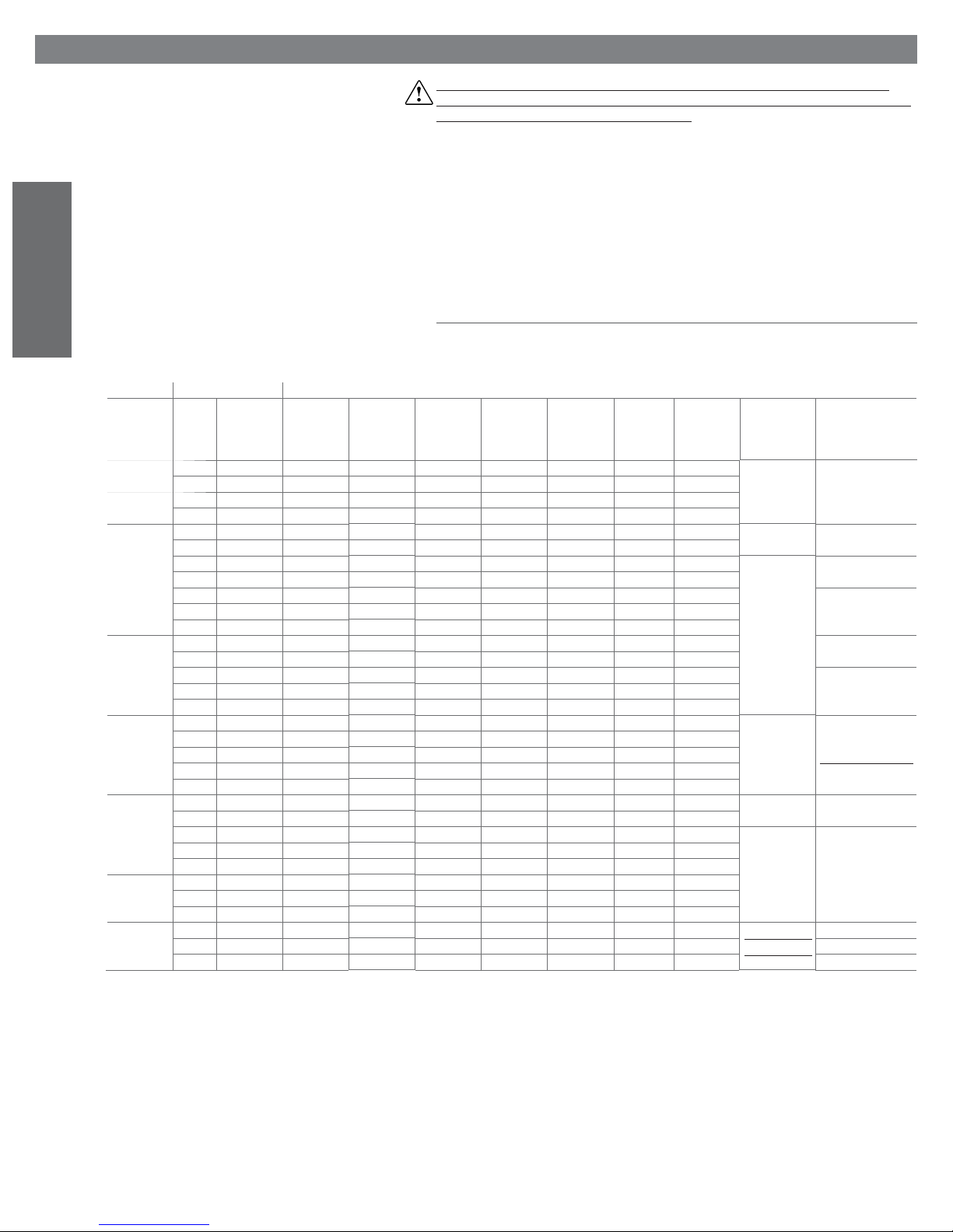
Table 7.1.1 sh ows the recommended cross-sections of the power cable and the recommended sizes of
the fuses; note, however, that this data is purely indicative and, in the event of non-conformity with local
standards, the latter must prevail.
ENGLISH
7.1 Power supply voltages
Table 7.a lists the electrical data regarding the power supply voltages of the various models and the functional characteristics of each. Note that some models may be powered at different voltages, obviously
with different consumption and steam production values.
power supply nominal characteristics
base model code voltage
(V - type)
(1)
elements
(no x W)
(2)
connection
(3)
type
current
(2)
(A)
power
(kW)
(2)
production
(kg/h) /(lbs/
(2) (5)
hr)
cable
section
(mm2)/
(4)
line fuses
(A / tipo)
(4)
electrical dia-
gram (Fig.)
(AWG)
UR002 U 208 - 1~N 1 x 29,5 - 7 1,5 2 /4.4 2,5/14 10 / rapid 7.p.a and 7.p.b 7.o.d
D 230 - 1~N 1 x 29,5 - 7,8 1,8 2,4 /5.29 2,5/14 10 / rapid
UR004 U 208 - 1~N 1 x 17,6 - 11,8 2,5 3,3 /7.27 2,5/14 16 / rapid
D 230 - 1~N 1 x 17,6 - 13 3 4 /8.8 2,5/14 16 / rapid
UR006 U 208 - 1~ 3 x 28,1
D 230 - 1~ 3 x 35,3
W 208 - 3~ 3 x 28,1
K 230 - 3~ 3 x 35,3
L 400 - 3~ 3 x 35,3
M 460 - 3~ 3 x 47,0
N 575 - 3~ 3 x 73,5
UR010 W 208 - 3~ 3 x 17,3
K 230 - 3~ 3 x 21,3
L 400 - 3~ 3 x 21,3
M 460 - 3~ 3 x 28,1
N 575 - 3~ 3 x 44,0
22,2 4,6 6,2 /13.6 6/10 32 / rapid 7.p.c and 7.p.d 7.o.c
19,6 4,5 6 /13.2 6/10 25 / rapid
3 x 12,8 4,6 6,2 /13.6 2,5/14 16 / rapid 7.p.e and 7.p.f 7.o.b
3 x 11,3 4,5 6,0/13.2 2,5/14 16 / rapid
3 x 6,5 4,5 6,0/13.2 2,5/14 10 / rapid 7.o.a
3 x 5,7 4,5 6,0/13.2 2,5/14 10 / rapid
3 x 4,5 4,5 6,0/13.2 2,5/14 10 / rapid
3 x 20,8 7,5 10,0 /22.04 6/10 25 / rapid 7.o.b
3 x 18,8 7,5 10,0/22.04 6/10 25 / rapid
3 x 10,9 7,5 10,0/22.04 2,5/14 16 / rapid 7.o.a
3 x 9,4 7,5 10,0/22.04 2,5/14 16 / rapid
3 x 7,5 7,5 10,0/22.04 2,5/14 16 / rapid
UR020 W 208 - 3~ 6 x 16 2 3 x 45,1 16,2 21,6/47.6 16/6 50 / rapid 7.p.h and 7.p.g
K 230 - 3~ 6 x 21,5 2 3 x 37,1 14,7 19,7/43.4 16/6 50 / rapid
L 400 - 3~ 6 x 21,5
M 460 - 3~ 6 x 27
N 575 - 3~ 6 x 47
3 x 21,3 14,7 19,7/43.4 6/10 25 / rapid
3 x 19,7 115,7 21/46.3 4/12 20 / rapid
3 x 14,8 114,6 19,6/43.2 4/12 20 / rapid
UR027 W 208 - 3~ 6 x 12,0 2 3 x 60,0 21,6 28,8/63.5 25/14 80 / rapid 7.p.k and 7.p.l 7.o.e
K 230 - 3~ 6 x 16,0 2 3 x 49,8 19,8 26,4/58.2 16/6 60 / rapid
L 400 - 3~ 6 x 16,0
M 460 - 3~ 6 x 21,5
N 575 - 3~ 6x 34,0
UR040 L 400 - 3~ 6 x 10,5
M 460 - 3~ 6 x 14,0
N 575 - 3~ 6 x 22,0
UR060 L 400 - 3~ 9 x 10,5
M 460 - 3~ 9 x 14,0
N 575 - 3~ 9 x 22,0
3 x 28,6 19,8 26,4/58.2 10/8 50 / rapid 7.p.g and 7.p.h 7.o.f
3 x 24,7 19,7 26,3 /57.9 6/10 32 / rapid
3 x 19,5 19,4 26,0/57.3 6/10 25 / rapid
3 x 43,6 30,2 40,3/88.8 16/6 60 / rapid
3 x 38,1 30,3 40.4 /89 16/6 60 / rapid
3 x 30,2 30,0 40,1/88.4 10/8 50 / rapid
3 x 65,4 45,3 60,5/133.4 25/14 80 / rapid 7.p.i and 7.p.j
3 x 57,1 45,5 60,6/133.6 25/14 80 / rapid 7.o.g
3 x 45,3 45,1 60,1/132.5 16/6 50 / rapid 7.o.h
7.p.m and 7.p.n
7.p.i and 7.p.j
wiring diagram of
the heater connec-
tion (Fig.)
7.o.e
7.o.f
7.o.h
Tab. 7.a
(1)
Tolerance allowed on rated mains voltage: ± 10%.
(2)
Tolerance on rated values: +5%, -10% (EN 60335-1).
(3)
-: single-phase; :single-phase in parallel; : delta; : star.
(4)
Recommended values; referred to the laying of the cable in closed PVC or rubber raceways with a
length of 20 m; the standards in force must in any case be followed.
(5)
Instant steam production: the average steam production may be infl uenced by external factors, such
as: ambient temperature, water quality, steam distribution system.
18
heaterSteam +030222011 - rel. 2.1 - 21.05.2010
Page 19
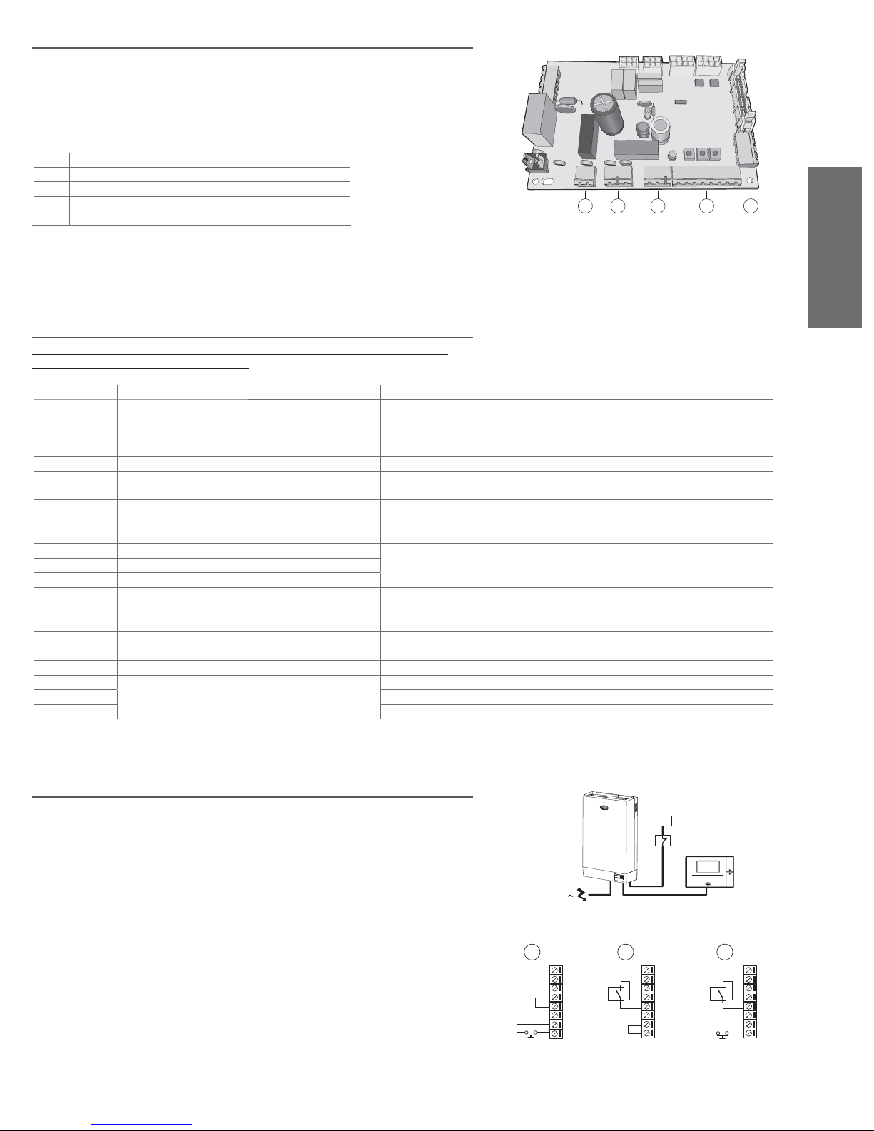
7.2 Main control board
The auxiliary connections, depending on the chosen model and the control module, must be made by
introducing the external cables into the electrical panel. For this purpose use the smaller fairlead on the
base of the machine, passing the cables through the raceway on the internal partition to the removable
screw terminals placed on the main control board, as shown in Fig. 7.a and described in the following
paragraph.
Key:
1. terminal block G (dehumidifi cation contact)
2. terminal block H (alarm contact)
3. remote manual DRAIN command terminal block K
4. terminal block I (control signals)
1 2 3 4 5
5. terminal block J (to remote terminal or supervisory system)
Fig. 7.a
7.3 Description of the terminal block and connections (functions
and electrical specifi cations)
Before connecting the probes or the external regulator, set parameters A2 and A6 according to the
control signal (see THE HUMIDIFIER CONTROLLER).
terminal function electrical characteristics
1I outlet probe signal input input impedance: 50 if programmed for 0 to 20 mA or 4 to 20 mA
2I GND
3I 32 Vdc derived from rectifying of 24 Vac; max 250 mA
4I 12 Vdc stabilised accuracy ± 5%; Imax=50 mA
5I room probe signal input or signal from external regulator input impedance: 50 if programmed for 0 to 20 mA or 4 to 20 mA
6I GND
7I remote enabling Rmax=50 ; Vmax=24 Vdc; Imax=10 mAdc
8I
1H NO alarm contact 250 V; 8A with resistive load; 2A with indicative load
2H common alarm contact
3H NC alarm contact
1G NO dehumidifi cation contact 250 V; 8A with resistive load; 2A with indicative load
2G common dehumidifi cation contact
1J 32 Vdc derived from rectifying of 24 Vac; max 250 mA
2J L + standard RS485
3J L 4J GND
1K remote control terminal block button switch for DRAIN com2K common contact
mand with simultaneous disconnection of the power supply
3K NO contact
60 k if programmed for 0 to 1 V or 0 to 10 V or 2 to 10 V
60 k if programmed for 0 to 1V or 0 to 10V or 2 to 10 V
NC contact
ENGLISH
Tab. 7.b
7.4 Auxiliary connections
Before making the auxiliary connections, disconnect electrical power to the appliance!
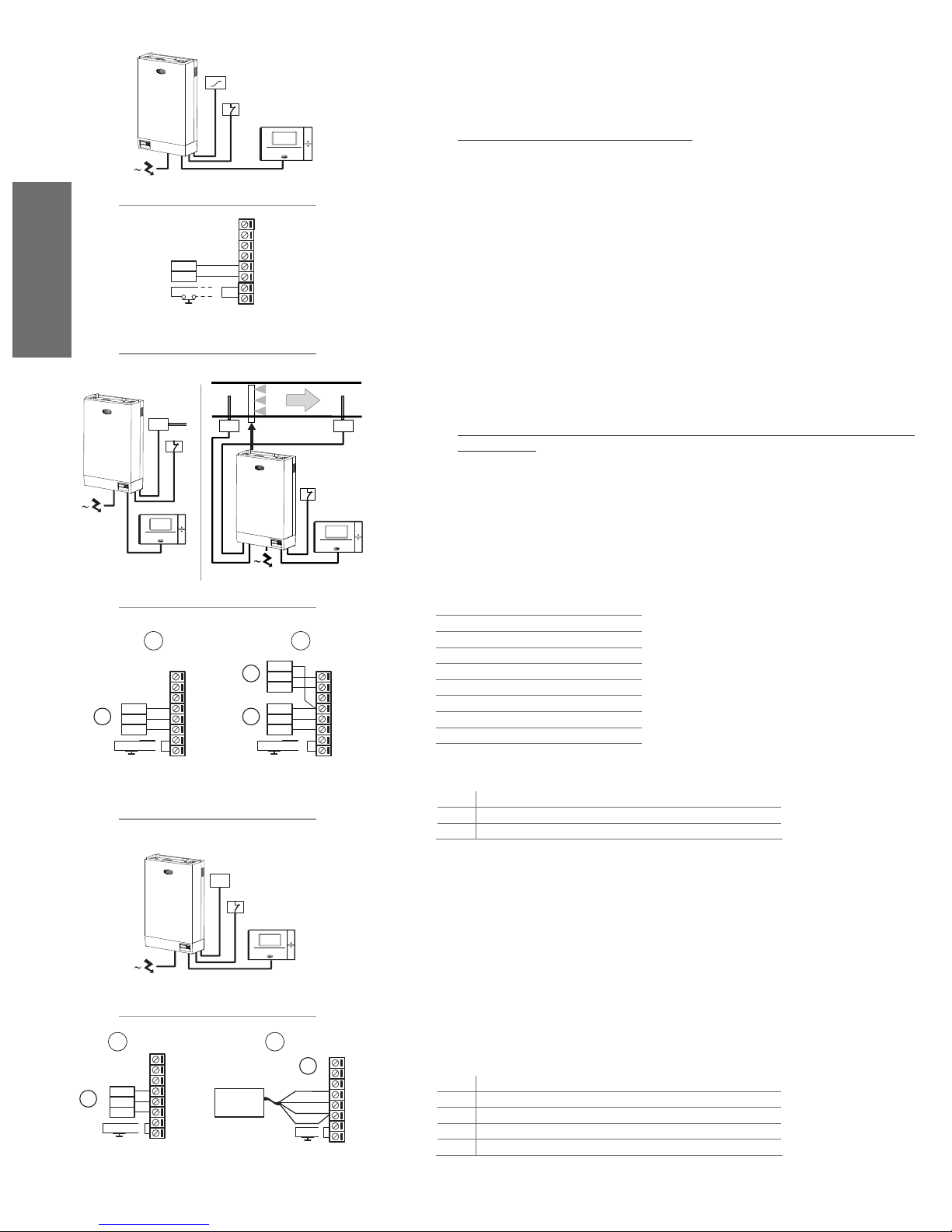
7.4.1 Type C control module with ON/OFF action
The humidifi er is controlled by a mechanical humidistat H or a voltage-free remote contact CR, or a
combination of both.
The control module can be connected to an RS485 serial line, or alternatively to the CAREL Humivisor
remote control panel, marked as MT, or to a remote supervisor.
The diagrams in Fig. 7.b and 7.c show the connections to be made on the terminal block I, in the
following cases:
a. action commanded by simple enabling contact;
b. action from external mechanical humidistat;
c. combination of the above.
heaterSteam +030222011 - rel. 2.1 - 21.05.2010
H
CR
humivisor
MT
Fig. 7.b
A
1I
2I
3I
4I
5I
6I
7I
8I
CR
B C
1I
2I
H
3I
4I
5I
6I
7I
8I
1I
2I
H
3I
4I
5I
6I
7I
8I
CR
Fig. 7.c
19
Page 20
ENGLISH
external
regulator
OUT
REF
CR
R
Fig. 7.d
Fig. 7.e
7.4.2 Type H control module with modulating action
The humidifi er with modulating action is fi tted with solid-state relays, and its capacity can be varied from
zero to 100% depending on the control requirements. In this case too, the humidifi er can be
connected via RS485 to the CAREL Humivisor MT remote control panel or a remote supervisor. It can be
CR
humivisor
MT
controlled in the following three different modes.
a) Slave control, with signal from an external regulator.
Steam production is managed by an external regulator R (Fig. 7.d) that transmits a modulating
signal to the control module; the control module can be programmed to receive alternatively one of
the following modulating signals (see THE HUMIDIFIER CONTROLLER):
• voltage signal: 0 to 1Vdc; 0 to 10Vdc; 2 to 10Vdc;
1I
2I
3I
4I
5I
6I
7I
8I
• current signal: 0 to 20mA; 4 to 20mA.
The reference (zero) of the external regulator must be connected to terminal 6I on terminal block I and
the control signal to terminal 5I (Fig. 5.e).
To avoid disturbances in control, the ground of the external regulator must be connected to the ground
of the control.
HT
humivisor
MT
HT CH
CR
Fig. 7.f
A
1l
2l
+ (G)
1 3
Out H
M
CR CR
3l
4l
5l
6l
7l
8l
Fig. 7.h
b) Autonomous modulating control with ambient relative humidity probe (and possible limiting probe
in the outlet duct)
With this confi guration (see Fig. 7.f) the main control board, connected to a humidity probe HT,
performs complete control according to the humidity measured.
CR
A limiting humidity probe in the outlet duct can also be added (see Fig. 7.g): with this confi guration,
typical of air handling systems, the main control board, connected to a humidity probe HT, performs complete control, as well as limiting the steam production depending on the value of relative
humivisor
MT
Fig. 7.g
humidity in the outlet duct, measured using the special probe CH.
The diagrams shown in Fig. 7.h indicate the connections to be made using CAREL probes, for:
• just one relative humidity probe;
• a limiting humidity probe in the outlet duct.
CAREL probes available for rooms
B
+ (G)
2
Out H
+ (G)
Out H
M
M
1l
2l
3l
4l
5l
6l
7l
8l
The control can be connected to non-CAREL active probes; see Using different brand probes.
ASWH100000
for air ducts
ASDH100000
ASDH200000
for special applications
ASPC230000
ASPC110000
Legenda:
1.
HT: CAREL humidity probe (intake probe)
2.
CH: CAREL limit probe (outlet probe)
3.
HT: CAREL humidity probe (intake probe)
TT
CR
humivisor
MT
Fig. 7.i
A
1l
2l
+ (G)
1
Out T
M
CR
3l
4l
5l
6l
7l
8l
SST00B/P40
B
1
2
3
4
5
CR
Fig. 7.j
7.4.3 Type T control module for steam baths with modulating action
The control of this appliance features autonomous internal control, and is connected to a temperature
probe TT (Fig. 7.i).
This performs complete control according to the temperature measured inside the environment being
controlled.
Fig. 7.4.3.2 shows the connection of CAREL probe model ASET030001, with a measurement range of
-30T90 °C (Fig. 7.j.A), or SST00B/P40 (Fig. 7.j.B). The CAREL recommended probes have a 0 to 1V
output. The control signal must be connected to terminal 5I, whose reference (GND) is represented
by terminal 6I. The control can be connected to non-CAREL active probes; see Using different brand
probes.
1l
2l
3l
4l
5l
6l
7l
8l
20
Key:
1.
TT: temperature CAREL probe
2. red
3. brown
4. black
5. white
heaterSteam +030222011 - rel. 2.1 - 21.05.2010
Page 21
7.5 Other auxiliary contacts
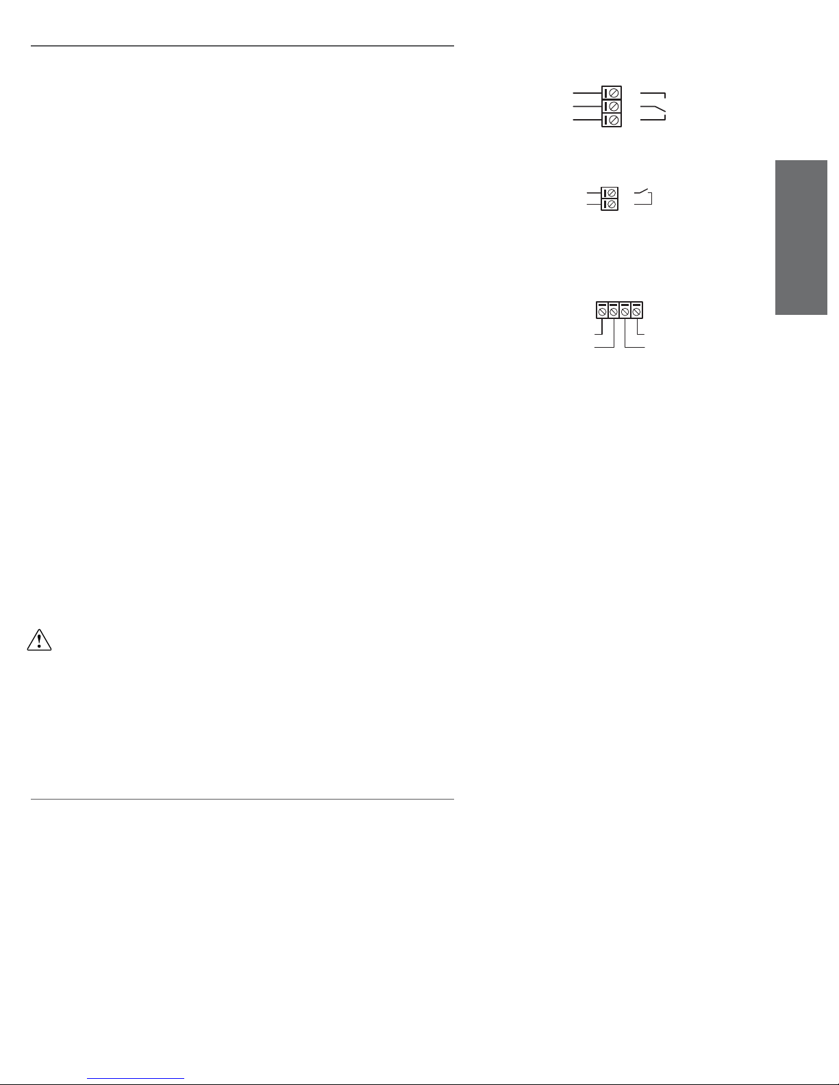
7.5.1 Alarm contact
The humidifi er’s control module features a voltage-free switching contact for the remote signalling of the
presence of one or more anomalous events or alarms.
Connection to the alarm contact (250 Vac; maximum load: 8 A resistive - 2 A inductive) is made using
the removable terminal block H, as per Fig. 7.l.
7.5.2 Dehumidifi cation contact
In the advanced version with internal control and humidity transducer, the control module features a
voltage-free NO contact, the closing of which can, if required, be programmed to activate an external
dehumidifi cation device: in this case the appliance assumes the functions of a complete ambient relative
humidity control.
Connection to the dehumidifi cation contact (250 Vac; maximum load: 8 A resistive - 2 A inductive) is
made using the removable terminal block G, as per Fig. 7.m.
1H
2H
3H
Fig. 7.l
1G
2G
Fig. 7.m
7.5.3 Remote terminal/supervisory system
The humidifi er’s control module can be connected to an RS485 serial line, as per the diagram in Fig. 7.n,
or alternatively to:
• a CAREL Humivisor remote control panel (see specifi c instruction manual), which can be connected
to four different humidifi ers;
• a remote supervisory system.
The transmission line can reach a maximum distance of 1000 metres between the two most distant
points.
7.5.4 Using different brand probes
Different brand probes can be used, with output signals selected, by programming the parameter A2,
(see THE HUMIDIFIER CONTROLLER) from the following:
• voltage signal: 0 to 1 Vdc; 0 to 10 Vdc; 2 to 10 Vdc;
• current signal: 0 to 20 mA; 4 to 20 mA.
In addition, the maximum and minimum values must be programmed for the signal (parameters A3 and
A4 for the room probe; A7 and A8 for the outlet probe).
The probes can be powered at the following voltages:
• 12 V stabilised at terminal 4I;
• 32 Vdc from the rectifying of 24 Vac at terminal 3I.
The control signals must be connected:
• for the control probe HT (TT in the case of controls for steam baths) to terminal 5I, whose reference
ground (GND) is terminal 6I;
• for the limiting probe CH, to terminal 1I, whose reference ground (GND) is terminal 2I.
IMPORTANT WARNINGS:
• To avoid disturbances to control, the ground of the probes or the external regulators must be electrically connected to the ground of the appliance’s control;
• For humidifi er operation terminals 7I and 8I must be connected by an enabling contact or a jumper
(default solution). If terminals 7I and 8I are not connected, all internal and external devices com
manded by the control are disabled.
24 Vaux
1J 2J 3J 4J
L+
ENGLISH
GND
L-
Fig. 7.n
7.6 Checks
The following conditions represent correct electrical connection:
• the rated voltage of the appliance corresponds to the voltage on the specifi cation plate;
• the fuses installed are suitable for the line and the voltage of the power supply;
• a line cut-off switch has been installed to enable power to the
humidifi er to be disconnected;
• the electrical connections have been made as per the diagrams;
• the power cable is fastened to the tear-proof cable clamp;
• terminals 7I and 8I are connected by jumper or an enabling contact;
• the ground of any non-CAREL probes is electrically connected to the ground of the control;
• if the appliance is commanded by an external regulator, the ground of the signal is electrically
connected to the controller’s ground.
heaterSteam +030222011 - rel. 2.1 - 21.05.2010
21
Page 22
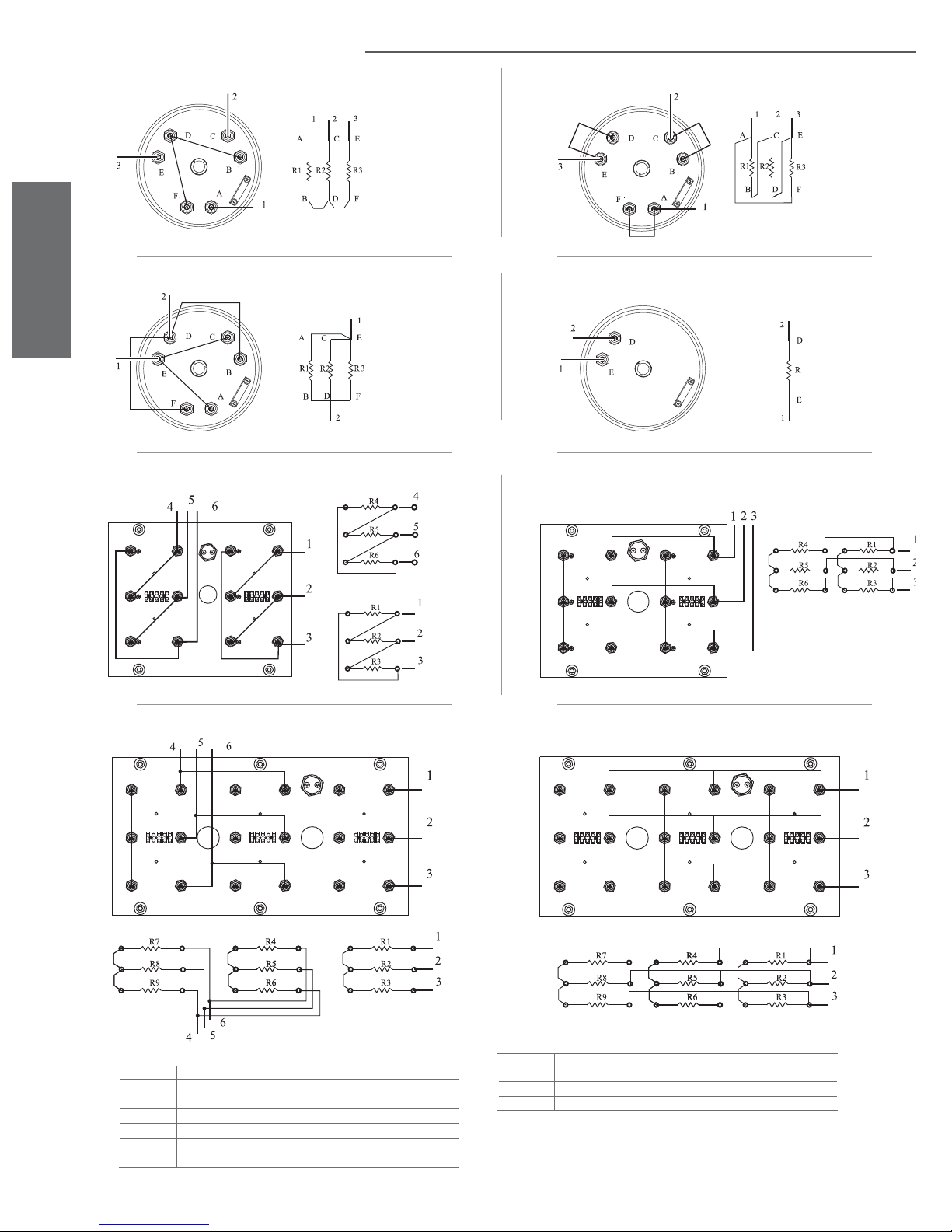
7.7 Wiring diagrams for the connection of the heating elements
Star three-phase connection (6-10 kg/h) (13.2-22 lbr/h)
Pparallel single-phase connection (6 kg/h) (13.2 lbr/h)
ENGLISH
Delta three-phase connection (20-27 kg/h) (44-59.5 lbr/h)208/230 V
Fig. 7.o.a
Fig. 7.o.c
Delta three-phase connection (6-10 kg/h) (13.2-22 lbr/h)
Fig. 7.o.b
Star three-phase connection (2-4 kg/h) (4.4-8.8 lbr/h)
Fig. 7.o.d
Sstar three-phase connection (20-27-40 kg/h) (44-59.5-88 lbr/h) 400/460/575 V
Star three-phase connection (60 kg/h) (132.2 lbr/h) 460 V
Key
1-2-3-4-5-6 three-phase power supply terminals
1-2 single-phase power supply terminals
Fig. 7.o.a
Fig. 7.o.c
Fig. 7.o.b
Fig. 7.o.d
Fig. 7.o.e
three-phase star connection (6-10Kg/h)
single-phase parallel connection (6kg/h)
three-phase delta connection (6-10kg/h)
single-phase connection (2-4kg/h)
three-phase parallel connection (20-27Kg/)
(13.2-22 lbr/h)
(4.4-8.8 lbr/h)
(13.2 lbr/h)
(13.2-22 lbr/h)
(44-59.5 lbr/h) 208/230 V
Fig. 7.o.e
Fig. 7.o.g
Star three-phase connection (60 kg/h) (132.2 lbr/h) 400/575 V
Fig. 7.o.f
Fig. 7.o.g three-phase star connection (60 Kg/h)(132.2lbr/h) 460 V
Fig. 7..oh three-phase star connection (60 Kg/h) 400/575 V
three-phase star connection (20-27-40Kg/h)
400/460/575 V
(44-59.5-88 lbr/h)
Fig. 7.o.f
Fig. 7.o.h
Table 7.7c
22
heaterSteam +030222011 - rel. 2.1 - 21.05.2010
Page 23
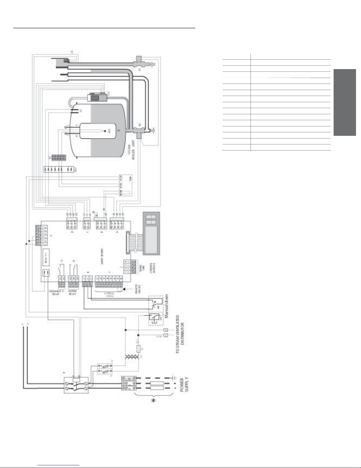
7.8 Single-phase wiring diagram for 2-4kg/h (4.4-8.8lbr/h)
humidifi ers with type C control module
* Carried out by the installer
TB Terminal block
THP Motor Protector
QC1-QC2 Quick connectors
K Contactor
LLC Level switches
ST Sensor terminal block
F1-F2 Power fuses
FV Fill valve
PTC Heater temperature sensor
TR Transformer
DV Drain valve
LS High level electrodes
MP Manual drain
CS Conductivity meter electrodes
MS Manual switch
R Electric heating element
ENGLISH
Fig. 7.p.a
WARNING:
BRIDGING CONNECTION see Fig. 7.o.d
heaterSteam +030222011 - rel. 2.1 - 21.05.2010
23
Page 24
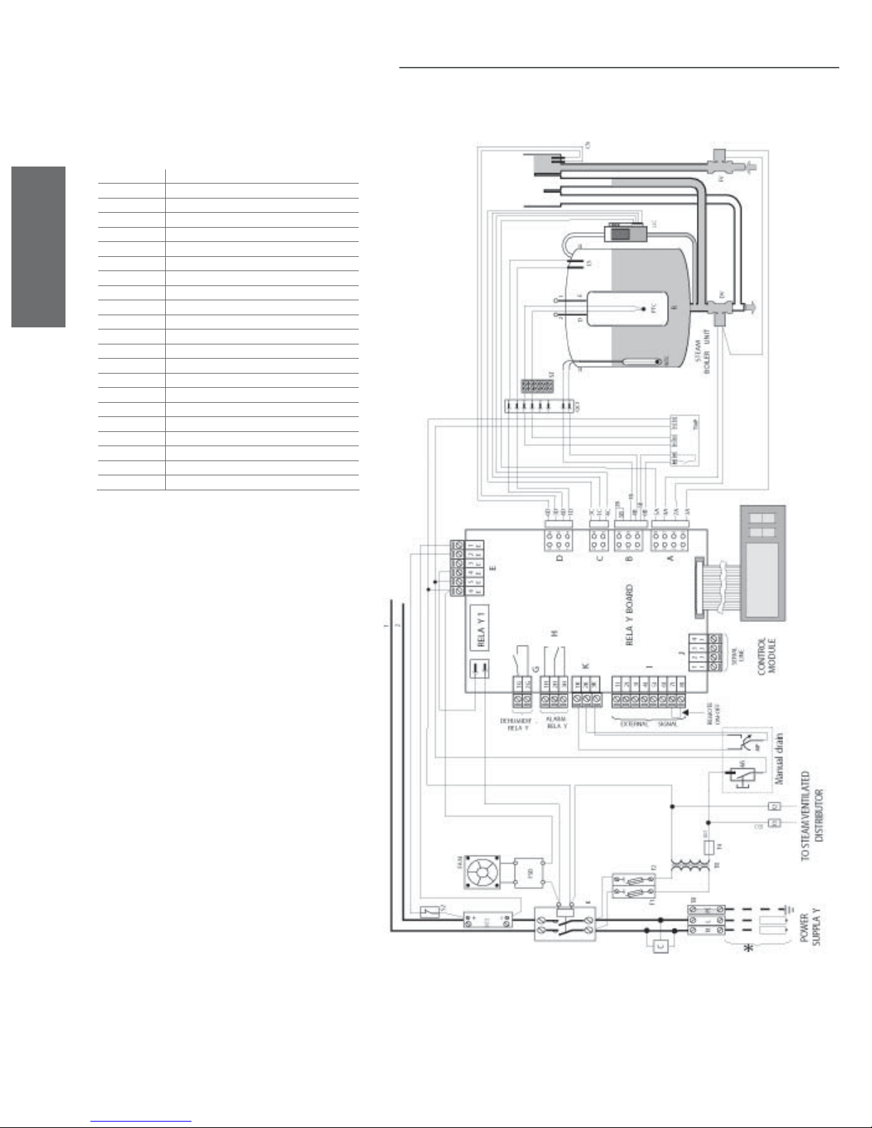
* Carried out by the installer
TB Terminal block
FV Fill valve
PTC Heater temperature sensor
K Contactor
DV Drain valve
NTC Water temperature sensor
F1-F2 Power fuses
LS High level electrodes
ENGLISH
FAN Fan
TR Transformer
CS Conductivity meter electrodes
FSB Fan control board
C Filter
SSR Solid state relay
MS Manual switch
R Electric heating element
S2 Circuit breaker
THP Motor Protector
QC1-QC2 Quick connectors
MP Manual drain
LLC Level switches
ST Sensor terminal block
7.9 Single-phase wiring diagram for 2-4kg/h (4.4-8.8lbr/h)
humidifi ers with type H or T control module
Fig. 7.p.b
WARNING:
BRIDGING CONNECTION see Fig. 7.o.d
24
heaterSteam +030222011 - rel. 2.1 - 21.05.2010
Page 25
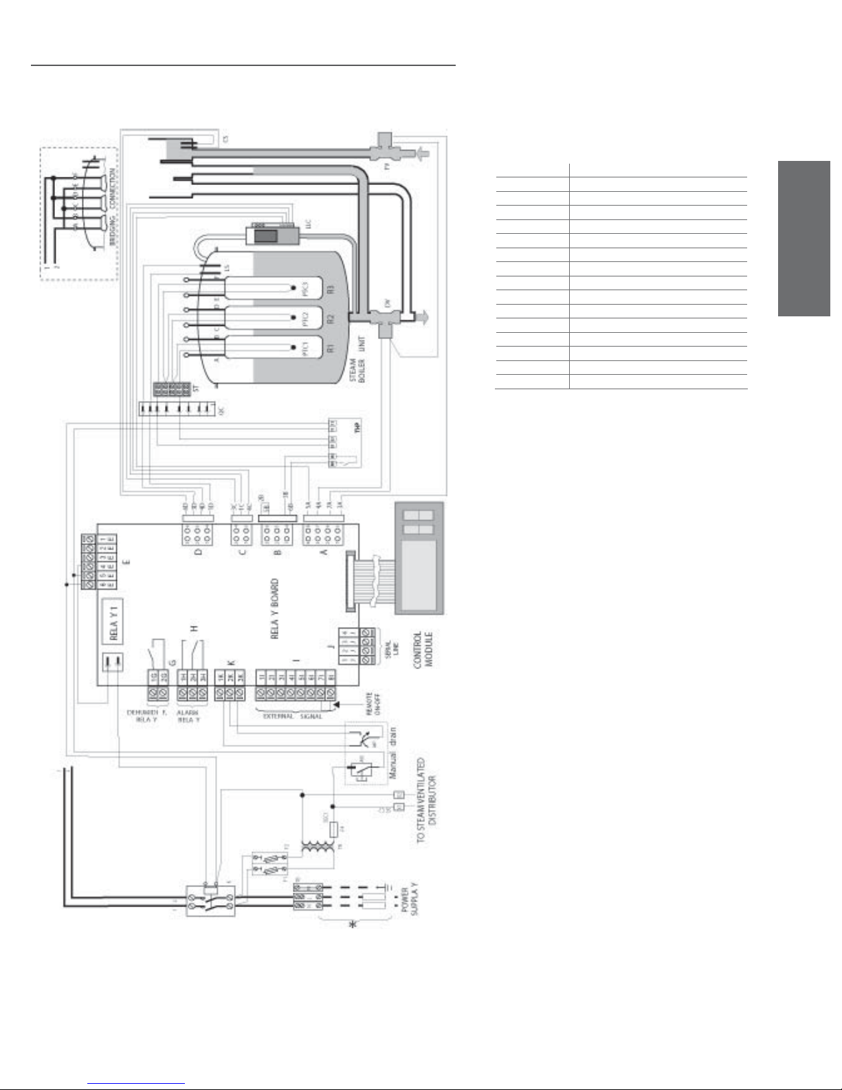
7.10 Single-phase wiring diagram for 6kg/h (13.2lbr/h)
humidifi ers with type C control module
* Carried out by the installer
TB Terminal block
THP Motor Protector
R1-R2-R3 Electric heating element
K Contactor
LLC Level switch
QC1-QC2 Quick connectors
F1-F2 Power fuses
FV Fill valve
ST Sensor terminal block
TR Transformer
DV Drain valve
PTC-PTC2-PTC3 Heater temperature sensors
LS High level electrodes
MP Manual drain
MS Manual switch
CS Conductivity meter electrodes
ENGLISH
Fig. 7.p.c
WARNING:
BRIDGING CONNECTION see Fig. 7.o.c
heaterSteam +030222011 - rel. 2.1 - 21.05.2010
25
Page 26
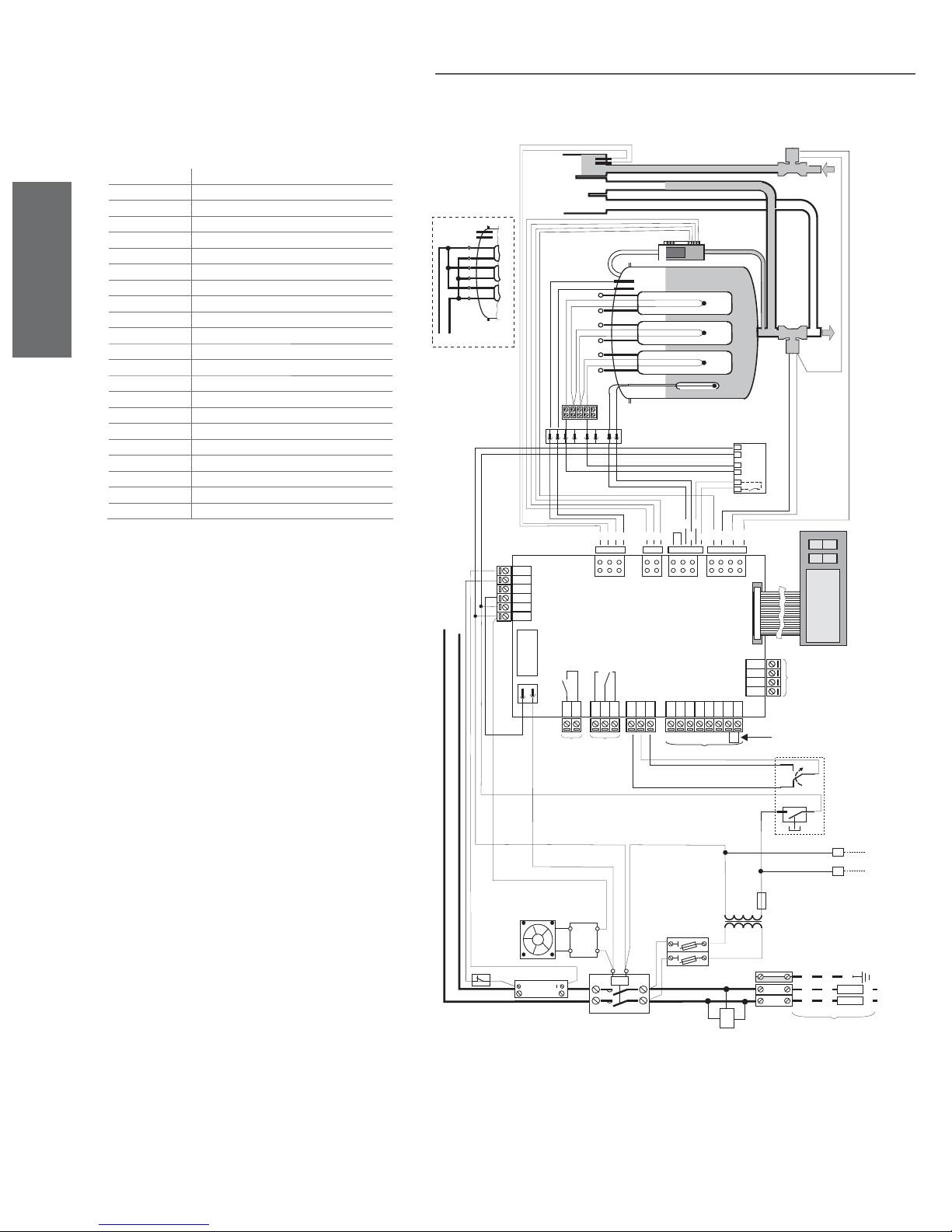
7.11 Single-phase wiring diagram for 6kg/h (13.2lbr/h)
humidifi ers with type H or T control module
* Carried out by the installer
TB Terminal block
FV Fill valve
PTC1-PTC2-PTC3 Heater temperature sensors
K Contactor
DV Drain valve
NTC Water temperature sensor
F1-F2 Power fuses
LS High level electrodes
FAN Fan
ENGLISH
TR Transformer
CS Conductivity meter electrodes
FSB Fan control board
C Filter
RSS Solid state relay
MS Manual switch
R1-R2-R3 Electric heating element
THP Motor Protector
QC1-QC2 Quick connectors
LLC Level switch
ST Sensor terminal block
MP Manual drain
S2 Circuit breaker
CS
FV
LLC
LS
ST
6D
654
321
FD
2B
654
321
PTC3PTC2PTC1
DV
R1 R2 R3
NTC
STEAM
BOILER UNIT
THP
M1 M2 S1 S2 T1 T2
1B
3B
4A7A3A
5A
4B
6B
5B
876
5
432
B
1
A
E
ABC
QC1
4D1D3D
3C1C4C
4
3
2
1
D
C
AB CDE F
BRIDGING CONNECTION
2
1
1
E
2
E
3
E
E
4
E
5
E
6
1
2
E
REL AY 1
1G
2G
DEHUMIDI F.
RELA Y
FA N
S2
+
RSS
WARNING:
BRIDGING CONNECTION see Fig. 7.O.C
G
FSB
1H2H3H
1H2H3H
ALAR M
RELA Y
H
1K2K3K
K
K
REL AY BOARD
I
1I2I3I4I5I6I7I
SIGNAL
EXTERNAL
F2
F1
J
4
J
3
J
J
2
1
8I
C
LINE
SERIAL
J
REMOTE
ON-OFF
SEC1
F4
TR
TB
PE
NL
MODULE
CONTROL
MP
MS
Manual drain
X2X1
SE
2
C
DISTRIBUTOR
TO STEAM VENTILATED
*
POWER
SUPPLA Y
Fig. 7.p.d
26
heaterSteam +030222011 - rel. 2.1 - 21.05.2010
Page 27
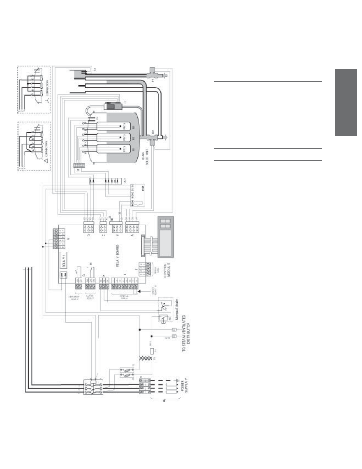
7.12 Three-phase wiring diagram for 6-10Kg/h (13.2-22lbr/h)
humidifi ers with type C control module
* Carried out by the installer
TB Terminal block
THP Motor Protector
R1-R2-R3 Electric heating element
K Contactor
LLC Level switch
QC1-QC2 Quick connectors
F1-F2 Power fuses
FV Fill valve
ST Sensor terminal block
TR Transformer
DV Drain valve
PTC1-PTC2-PTC3 Heater temperature sensors
LS High level electrodes
MP Manual drain
CS Conductivity meter electrodes
MS Manual switch
ENGLISH
Fig. 7.p.e
WARNING:
BRIDGING CONNECTION see Fig. 7.o.a e 7.o.b
heaterSteam +030222011 - rel. 2.1 - 21.05.2010
27
Page 28
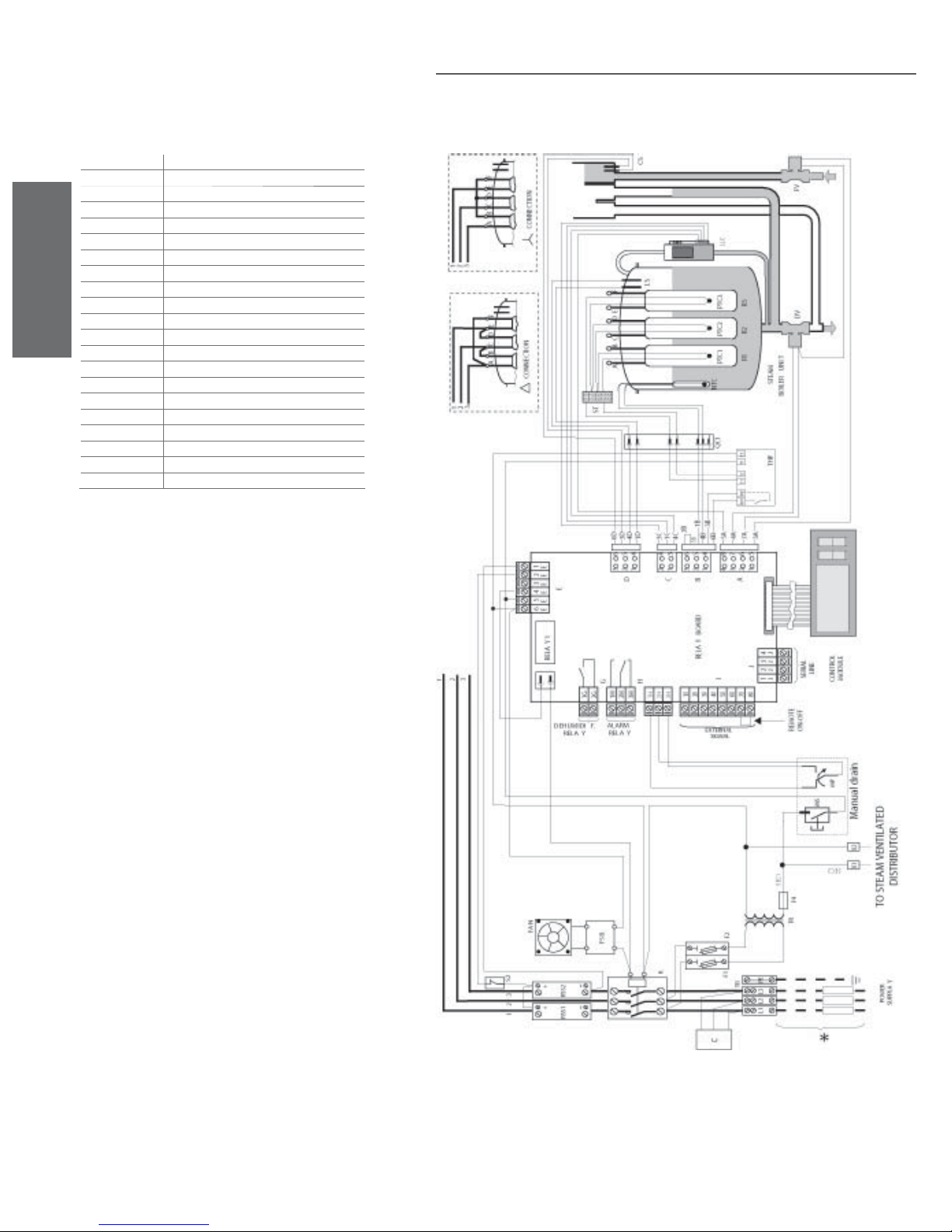
* Carried out by the installer
TB Terminal block
FV Fill valve
PTC1-PTC2-PTC3 Heater temperature sensors
K Contactor
DV Drain valve
NTC Water temperature sensor
F1-F2 Power fuses
LS High level electrodes
FAN Fan
TR Transformer
ENGLISH
CS Conductivity meter electrodes
FSB Fan control board
C Filter
RSS1-RSS2 Solid state relay
MS Manual switch
R1-R2-R3 Electric heating element
LLC Level switch
QC1-QC2 Quick connectors
THP Motor Protector
MP Manual drain
S2 Circuit breaker
7.13 Three-phase wiring diagram for humidifi ers with type H or
T control module
Fig. 7.p.f
WARNING:
BRIDGING CONNECTION see fi g. 7.o.a. e 7.o.b
28
heaterSteam +030222011 - rel. 2.1 - 21.05.2010
Page 29
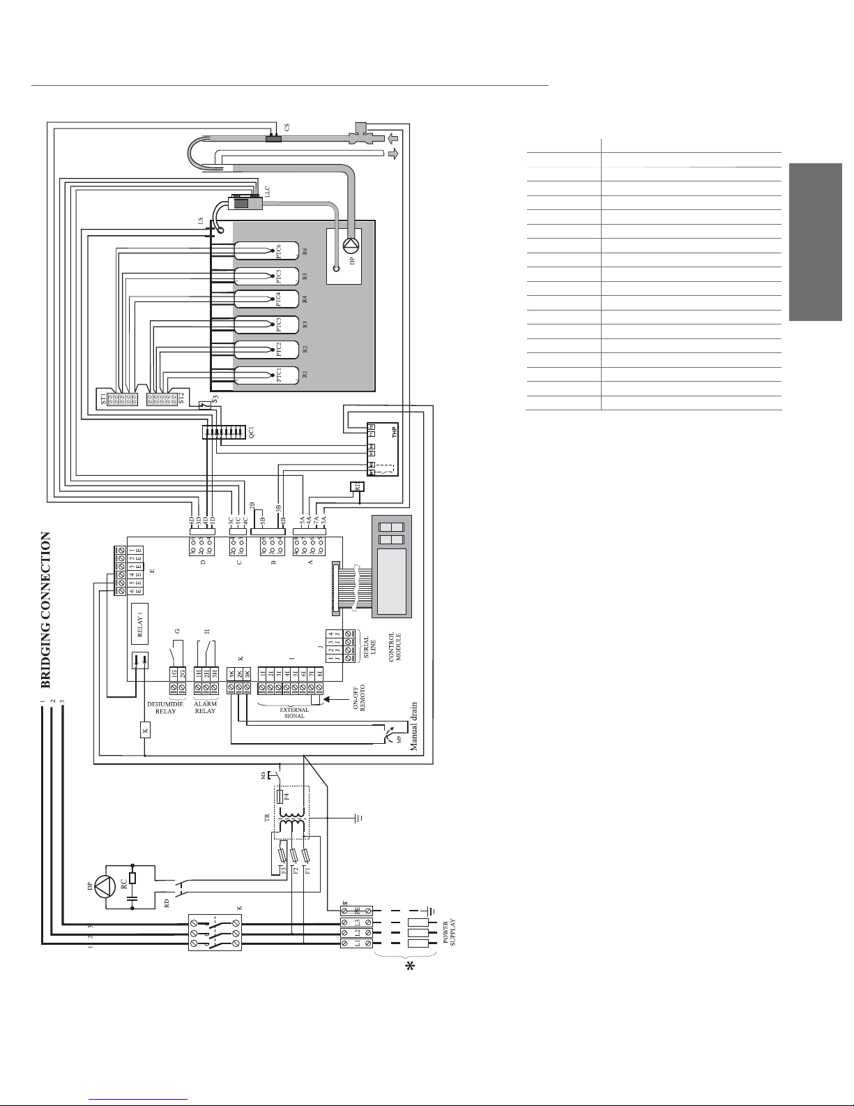
7.14 Three–phase electrical diagram for 20 (44lbr/h) ( 208-230-400-460-
5756V) 27-40Kg/h (59.5-88lbr/h) (400-460-575V) humidifi ers with type C
control module 400-460-575 V
* Carried out by the installer
TB Terminal block
FV Fill valve
PTC1 to PTC6 Heater temperature sensors
K Contactor
DP Drain pump
FAN E.P. Fan elecrtical panel
F1-F2-F3 Power fuses
LS High level electrodes
F4 Low voltage fuse
TR Transformer
CS Conductivity meter electrodes
THP Motor Protector
MS Manual switch
RD Pump control relay
LLC Level switches
R1 to R6 Electric heating element
MP Manual drain
QC1 Quick connectors
S3 Circuit breaker
ENGLISH
WARNING:
BRIDGING CONNECTION see Fig. 7.o.f
RELAY BOARD
Fig. 7.p.g
heaterSteam +030222011 - rel. 2.1 - 21.05.2010
29
Page 30
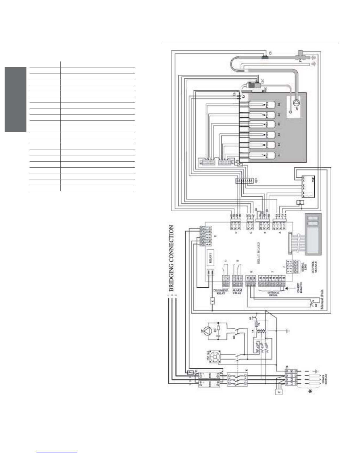
* Carried out by the installer
TB Terminal block
FV Fill valve
PTC1 to PTC6 Heater temperature sensors
K Contactor
DP Drain pump
FAN E.P. Fan elecrtical panel
F1-F2-F3 Power fuses
LS High level electrodes
F4 Low voltage fuse
ENGLISH
TR Transformer
CS Conductivity meter electrodes
THP Motor Protector
MS Manual switch
RD Pump control relay
NTC Water temperature sensor
LLC Level switches
R1 to R6 Electric heating element
RSS1-RSS2 Solid state relay
MP Manual drain
QC1 Quick connectors
C Filter
S2-S3 Circuit breaker
7.15 Three–phase electrical diagram for 20 (44lbr/h)
( 208-230-400-460-5756V) 27-40Kg/h (59.5-88lbr/h)
(400-460-575V) humidifi ers with type H control module
400-460-575 V
Fig. 7.p.h
WARNING:
BRIDGING CONNECTION see Fig. 7.o.f
30
heaterSteam +030222011 - rel. 2.1 - 21.05.2010
Page 31
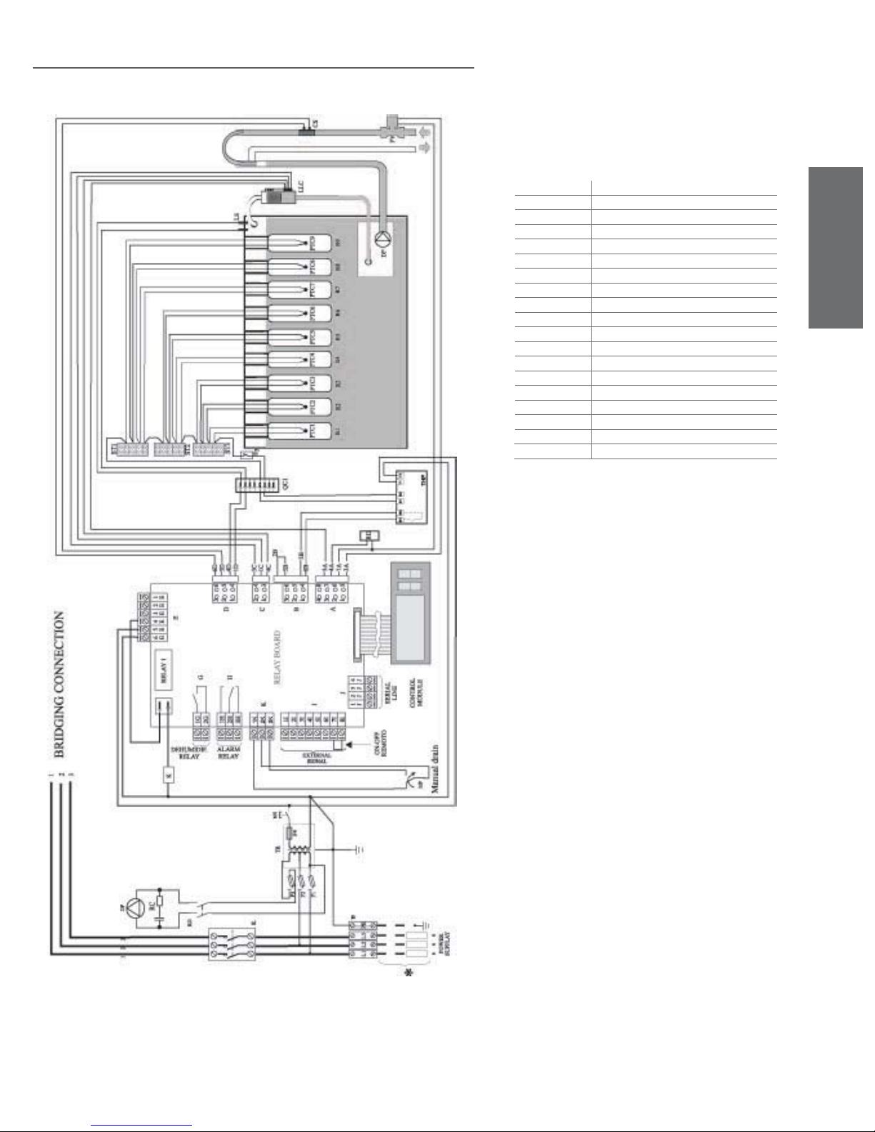
7.16 Three–phase electrical diagram for 60Kg/h (132.2lbr/h)
humidifi ers with type C control module 400-575 V
* Carried out by the installer
TB Terminal block
FV Fill valve
PTC1…PTC9 Heater temperature sensors
K Contactor
DP Drain pump
FAN E.P. Fan elecrtical panel
F1-F2-F3 Power fuses
LS High level electrodes
F4 Low voltage fuse
TR Transformer
CS Conductivity meter electrodes
THP Motor Protector
MS Manual switch
RD Pump control relay
LLC Level switches
R1 to R9 Electric heating element
MP Manual drain
QC1 Quick connectors
S3 Circuit breaker
ENGLISH
Fig. 7.p.i
WARNING:
BRIDGING CONNECTION see Fig. 7.o.h
heaterSteam +030222011 - rel. 2.1 - 21.05.2010
31
Page 32
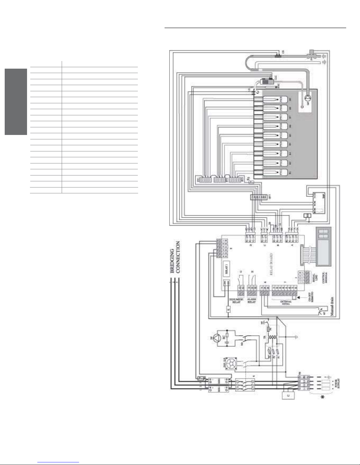
* Carried out by the installer
TB Terminal block
FV Fill valve
PTC1 to PTC9 Heater temperature sensors
K Contactor
DP Drain pump
FAN E.P. Fan elecrtical panel
F1-F2-F3 Power fuses
LS High level electrodes
F4 Low voltage fuse
TR Transformer
ENGLISH
CS High level electrodes
THP Motor Protector
MS Manual switch
RD Pump control relay
NTC Water temperature sensor
LLC Level switches
R1 to R9 Electric heating element
RSS1-RSS2 Solid state relay
MP Manual drain
QC1 Quick connectors
C Filter
S2-S3 Circuit breaker
7.17 Three–phase electrical diagram for 60Kg/h (132.2lbr/h)
humidifi ers with type H control module 400-575 V
Fig. 7.p.j
WARNING:
BRIDGING CONNECTION see Fig. 7.o.h
32
heaterSteam +030222011 - rel. 2.1 - 21.05.2010
Page 33
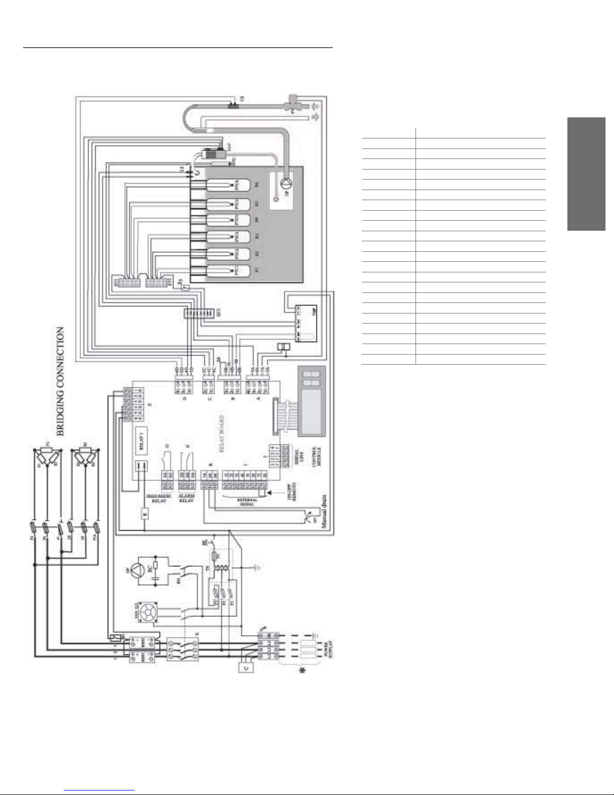
7.18 Three–phase electrical diagram for 27Kg/h (59.5lbr/h)
humidifi ers with type H control module at 208 - 230 V
* Carried out by the installer
TB Terminal block
FV Fill valve
PTC1 to PTC6 Heater temperature sensors
K1-K2 Contactor
DP Drain pump
FAN E.P. Fan elecrtical panel
F1-F2-F3 Power fuses
LS High level electrodes
F4 Low voltage fuse
TR Transformer
CS Conductivity meter electrodes
THP Motor Protector
MS Manual switch
RD Pump control relay
NTC Water temperature sensor
LLC Level switches
R1 to R6 Electric heating element
RSS1-RSS2 Solid state relay
MP Manual drain
QC1 Quick connectors
C Filter
F5 to F10 load protection fuses
S2-S3 Circuit breaker
ENGLISH
Fig. 7.p.k
WARNING:
BRIDGING CONNECTION see Fig. 7.o.e
heaterSteam +030222011 - rel. 2.1 - 21.05.2010
33
Page 34
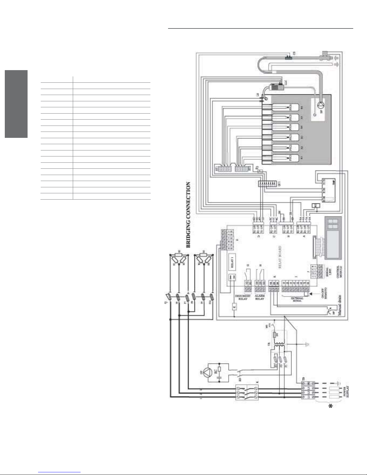
* Carried out by the installer
TB Terminal block
FV Fill valve
PTC1 to PTC6 Heater temperature sensors
K1-K2 Contactor
DP Drain pump
FAN E.P. Fan elecrtical panel
F1-F2-F3 Power fuses
ENGLISH
LS High level electrodes
F4 Low voltage fuse
TR Transformer
CS Conductivity meter electrodes
THP Motor Protector
MS Manual switch
RD Pump control relay
LLC Level switches
R1 to R6 Electric heating element
MP Manual drain
QC1 Quick connectors
F5...F10 load protection fuses
S3 Circuit breaker
7.19 Three–phase electrical diagram for 27Kg/h (59.5lbr/h)
humidifi ers with type H control module at 208 - 230 V
Fig. 7.p.l
WARNING:
BRIDGING CONNECTION see Fig. 7.o.e
34
heaterSteam +030222011 - rel. 2.1 - 21.05.2010
Page 35
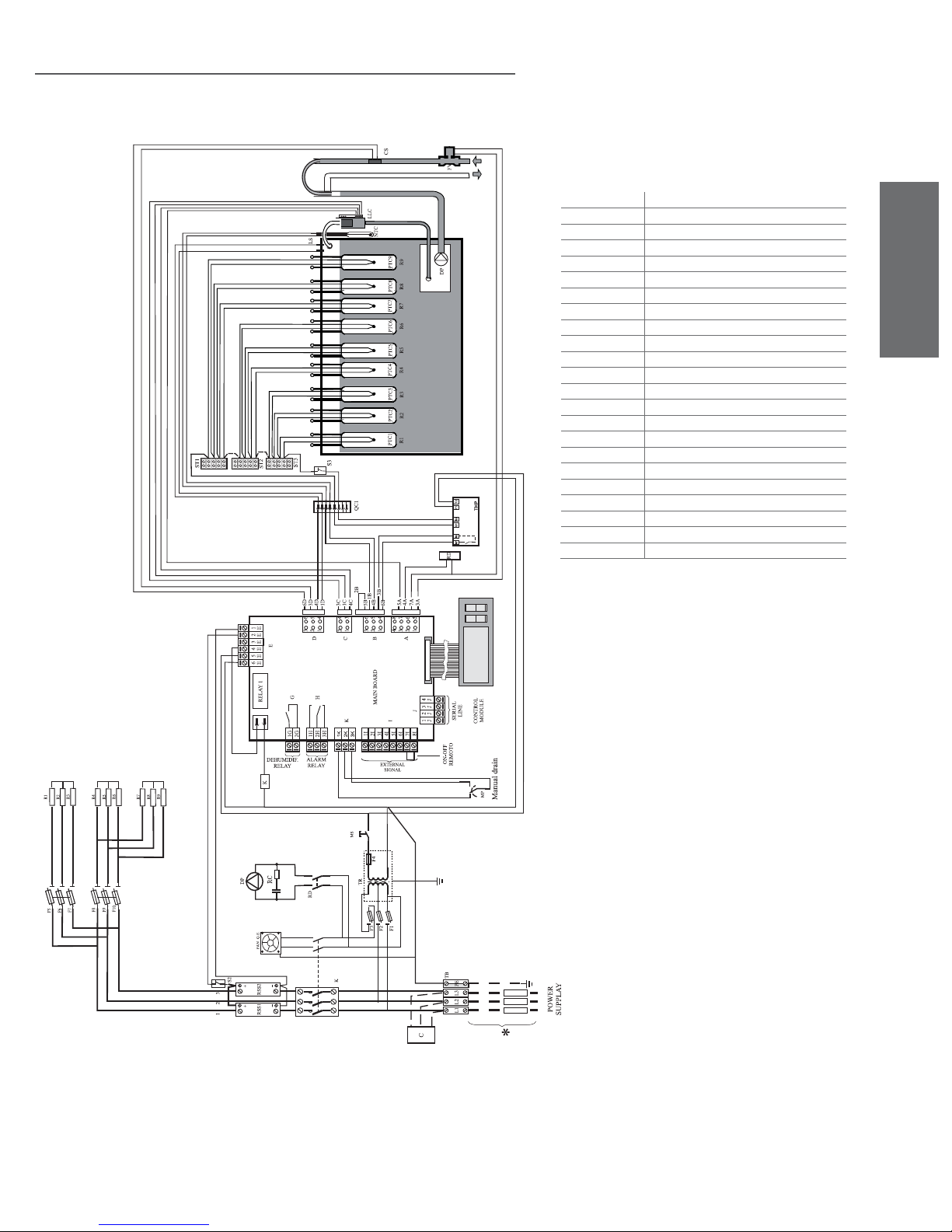
7.20 Three-phase electrical diagram for 60kg/h (132.2lbr/h)
humidifi ers with type H control module at 460 V
* Carried out by the installer
TB Terminal block
FV Fill valve
PTC1 to PTC9 Heater temperature sensors
K Contactor
DP Drain pump
FAN E.P. Fan elecrtical panel
F1-F2-F3 Power fuses
LS High level electrodes
F4 Low voltage fuse
TR Transformer
CS High level electrodes
THP Motor Protector
MS Manual switch
RD Pump control relay
NTC Water temperature sensor
LLC Level switches
R1 to R9 Electric heating element
RSS1-RSS2 Solid state relay
MP Manual drain
QC1 Quick connectors
C Filter
F5 to F10 load protection fuses
S2-S3 Circuit breaker
ENGLISH
Fig. 7.p.m
WARNING:
BRIDGING CONNECTION see Fig. 7.o.g
heaterSteam +030222011 - rel. 2.1 - 21.05.2010
35
Page 36
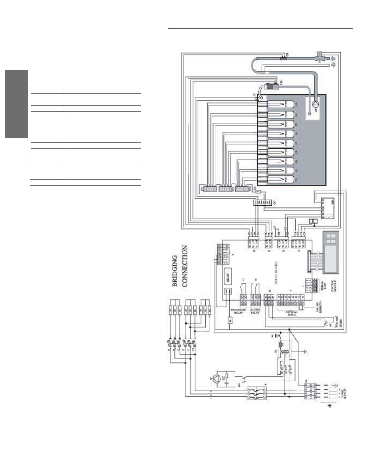
* Carried out by the installer
TB Terminal block
FV Fill valve
PTC1 to PTC9 Heater temperature sensors
K Contactor
DP Drain pump
FAN E.P. Fan elecrtical panel
F1-F2-F3 Power fuses
LS High level electrodes
F4 Low voltage fuse
TR Transformer
ENGLISH
CS Conductivity meter electrodes
THP Motor Protector
MS Manual switch
RD Pump control relay
LLC Level switches
R1 to R9 Electric heating element
MP Manual drain
QC1 Quick connectors
F5 to F10 load protection fuses
S3 Circuit breaker
7.21 Three-phase electrical diagram for 60kg/h (132.2lbr/h)
humidifi ers with type C control module at 460 V
Fig. 7.p.n
WARNING:
BRIDGING CONNECTION see Fig. 7.o.g
36
heaterSteam +030222011 - rel. 2.1 - 21.05.2010
Page 37
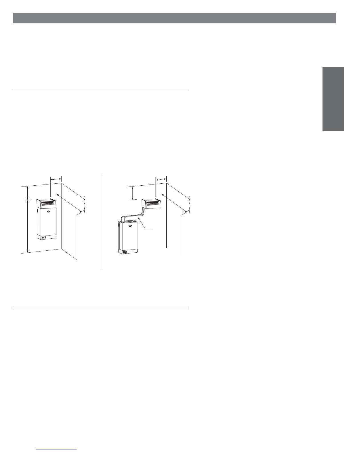
8. STEAM DISTRIBUTION
For optimal performance of the humidifi er, the steam produced must be introduced into the room/duct
in a uniform way, without projecting droplets and without noticeable condensation, using ventilated
steam distributors or linear distributors. The steam distributor must be chosen according to the place
where the steam is introduced. If the steam is to be distributed directly into the environment (rooms,
warehouses, etc.), the ventilated steam distributors used (optional) should be fi tted with a motorised fan.
If, on the other hand, the steam is to be introduced into a duct or air handling system, linear distributors
must be used, which exploit the speed of the air itself for distribution.
8.1 Ambient steam distribution: ventilated steam distributors
Ventilated steam distributors, used to distribute steam directly into the environment, can be mounted
onto the humidifi er (see Fig. 8.a) or positioned separately and connected to the humidifi er (see Fig. 8.b)
using steam pipes.
The drawings show the minimum recommended distances to prevent the fl ow of humidifi ed air from
coming into direct contact with persons, lights, electrical appliances, false ceilings and cold surfaces
before the steam is completely absorbed by the environment.
For further details on the mounting and use of ventilated steam distributors, please refer to the specifi c
instruction manual.
ENGLISH
>0,5
≥2,1
>0,5
>0,5
>5
Fig. 8.a Fig. 8.b
>0,5
>5
L ≤4
8.2 Steam distribution in cold rooms
It is possible to humidify a cold room using a ventilated steam distributor, ensuring that this works
within the limits of its operating range. The cold room must have an operating temperature between
-10 °C (14°fH) and +40 °C (104°fH), with a relative humidity of not over 80% rH. If these limits are not
possible, the steam can be distributed in the cold room using a linear distributor.
In any case, the steam must not come into direct contact with cold air streams from the cold room’s
refrigeration unit, to avoid possible re-condensation.
heaterSteam +030222011 - rel. 2.1 - 21.05.2010
37
Page 38
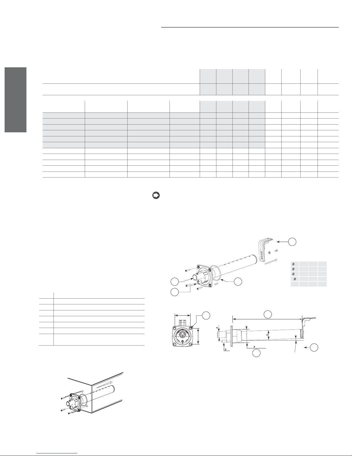
8.3 Ducted steam distribution: linear and concentrated jet
distributors (OEM)
For steam distribution in air ducts, the steam distributor must be suitably proportioned to the power of
the humidifi er and the cross-section of the ducts. For this purpose, CAREL supplies two ranges of linear
distributors: one of stainless steel, with plastic ends.
Figures 8.c and 8.d provide the dimensions of CAREL distributors.
Table 8.a indicates the minimum number and model of the distributors recommended for the type of
humidifi er used.
ENGLISH
humidifi er fi tting ø mm / ø inch
humidifi er capacity kg/h / lbs/hr 2
distributor fi tting mm/
inch (øA)
30 / 1.18 5 / 11 343 / 13.5 DP035D30R0 1 1
30 / 1.18 8 / 17.6 427 / 16.8 DP045D30R0 1 1 1
30 / 1.18 12 / 26.4 596 / 23.5 DP060D30R0 1 1 1
30 / 1.18 18 / 39.6 850 / 33.5 DP085D30R0 1 1 1
30 / 1.18 18 / 39.6 1048 / 41.3 DP105D30R0 1 1 1 (2)*
30 / 1.18 18 / 39.6 1245 / 49 DP125D30R0 1 1 1 (2)*
40 / 1.57 25 / 55 834 / 32.8 DP085D40R0 1 1 (2)* (4)**
40 / 1.57 35 / 77 1015 / 39.9 DP105D40R0 1 1 (2)* 2
40 / 1.57 45 / 99 1222 / 48.1 DP125D40R0 1 1 1 2
40 / 1.57 45 / 99 1636 / 64.4 DP165D40R0 1 1 2
40 / 1.57 45 / 99 2025 / 79.7 DP205D40R0 1
max. distributor capa-
city kg/h / lbs/hr
length (L) mm
/ inch
code UR002 UR004 UR006 UR010 UR020 UR027 UR040 UR060
30/
1.18
/ 4.44 / 8.86 /13.2
30
1.18
/
30/
1.18
30/
1.18
10
/2220 /44
40/
1.5 7
40/
1.5 7
27 /59.4 40
N.B.: if the duct is not wide enough for the distributors can be used (numbers shown in the brackets),
splitting the steam hose into two.
* : kit available with 30x40x30 “Y” connector, code UEKY000000 to split one 40 mm/1.57 inch outlet
into two 30 mm/1.18 inch outlets;
** : from 01/01/2005, kit available with 40x40x40 “Y” connector for the steam hose, code UEKY40x400,
to split one 40 mm/1.57 inch outlet into two 40 mm/1.57 inch outlets.
DP***D**R0 - linear distributors
1
40/
1.5 7
/88
2 x 4 0 /
2x1.57
60 /132
Table 8.a
Key:
1 fasten the support where envisaged
2 fl ange gasket
3 condensate drain
4 steam inlet
5 screws max. dia. “M5”
6 length (see table 8.a)
7 hole in wall
8 use the fastening support, supplied, to ensure the 2°
gradient due to the shape of the fl ange
> 2
Fig. 8.d
A 22 30 40
B 10 10 10
Y 58 68 89
4
2
3
X
5
A
X
B
6
Y
35 45 60
X 68 77 99
dimensions in mm
°2
8
7
Fig. 8.c
The linear distributors are mounted (see Fig. 8.d):
• by making a series of holes in the wall of the duct, as per the drilling template indicated in Figs.: 8.a
or 8.b;
• inserting the distributor with the steam outlet holes facing upwards;
• fastening the fl ange of the distributor using 3 screws.
To allow the condensate to return through the drain connection (see Installing the condensate return
pipe), mount the distributor at a slight angle (at least 2°-3° Fig. 8.c) with the inlet connection nearer than
the closed end, which, for this reason, must be adequately supported.
38
heaterSteam +030222011 - rel. 2.1 - 21.05.2010
Page 39
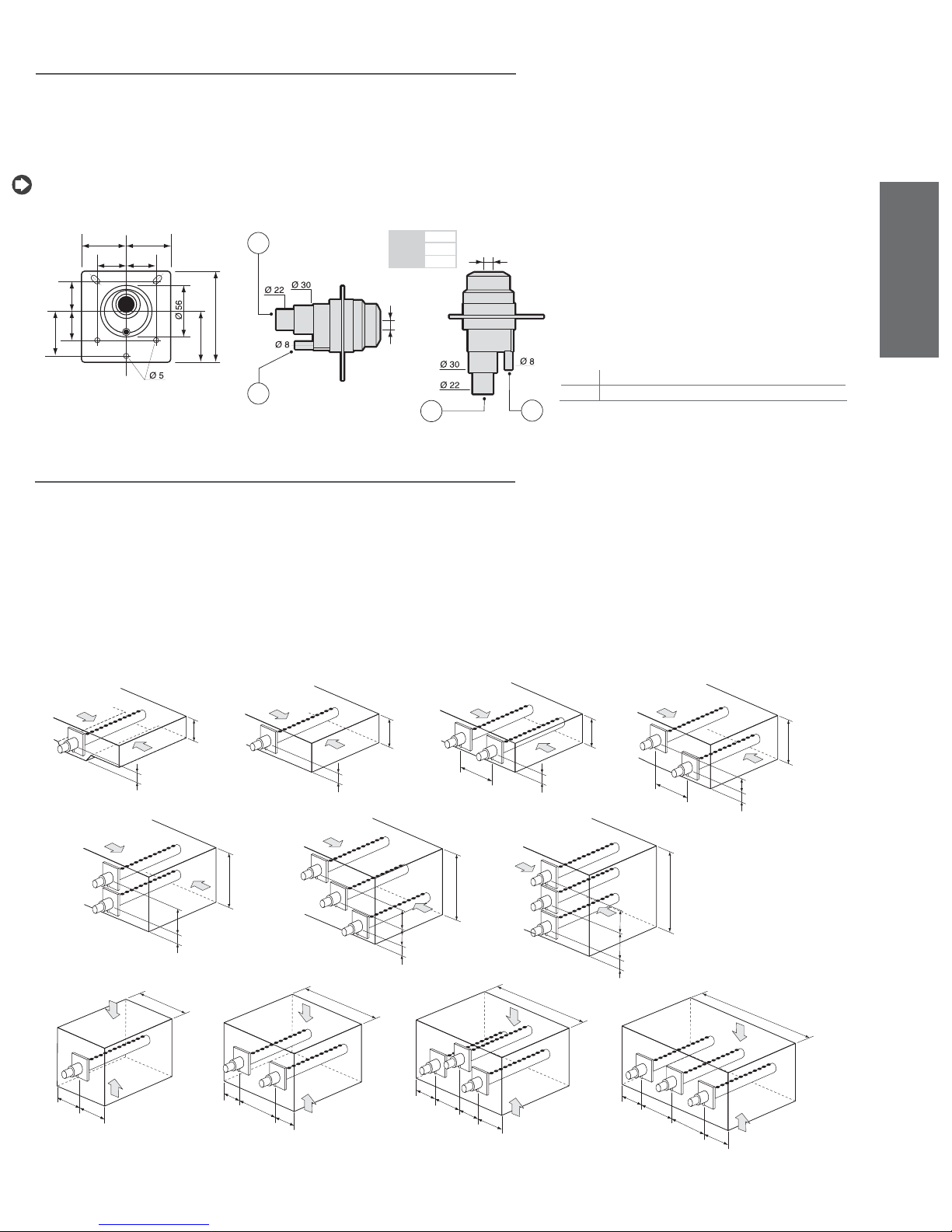
8.4 Concentrated jet steam distribution (OEM) (only for
humidifi ers up to 10 Kg/h/22 lbr/h)
For special applications (e.g. steam baths, technological machinery) a plastic OEM concentrated jet
distributor is available, with holes (12 or 22 mm)/(0.47 or 0.87 inch) or without, allowing the user to
make these according to requirements (see Fig. 8.e).
The OEM distributors can be fi tted, horizontally or vertically with the hole facing upwards, onto a support
with the same holes as per the drilling template for the aluminium linear distributor (see Fig. 8.e).
N.B.: when using steam tubing with an internal diamter of 30 mm/ 1.18 inch, remove the 22 mm/ 0.87 inch
steam inlet section.
50 50
1.24”
1.24”
31,5
31,5
1.9 6”
1.9 6”
31,531,5
1.24”
50
1.9 6”
1.24”
0.2”
2.2”
57,5
2.26”
100
1
1.18”
0.87”
3.94”
0.31”
2
OEM12 Y= 12
OEM22 Y= 22
OEM00 Y= 0
Y
1.18”
0.87”
0.87”
0”
0.47”
Y
1
Fig. 8.e
8.5 Positioning linear distributors in the air duct
Depending on the dimensions of the air duct, the distributors must be as long as possible and placed
away from curves, branches, changes in cross-section, grilles, fi lters, fans.
The minimum recommended distance between the steam distributor and the nearest obstacle is around
1 to 1.5 metres/3.28 to 4.92 feet, yet this strongly depends on the operating conditions; it in fact increases as a result of:
• the increase in speed of the air in the duct;
• the increase in relative humidity of the air before and, above all, after humidifi cation;
• the decrease in turbulence.
The distance can be shortened using a series of distributors in parallel.
Refer to the layout and the distances between the distributor and the walls of the duct and/or between
two distributors as shown in the following drawings.
0.31”
ENGLISH
key:
1 steam inlet
2 condensing drain
2
1
min. 200 mm
8”
≥ 70 mm
3”
5
1/3 H
2
H > 250 mm
10 ”
≥ 200 mm
8”
6
1/3 H
3
H > 250 mm
≥ 200 mm
2/5 H
1/5 H
4
H > 350 mm
14 ”
10 ”
7
8”
H > 400 mm
16 ”
2/5 H
1/5 H
8
min 200 mm
8”
9
H > 200 mm
2/7 H
2/7 H
1/7 H
10
8”
=
=
=
1/2 H
=
H > 500 mm
20”
2/7 H
1/7 H
H > 300 mm
12”
2/7 H
11
H > 600 mm
24”
H > 500 mm
20”
=
=
=
=
=
1/3 H
1/3 H
=
Fig. 8.f
heaterSteam +030222011 - rel. 2.1 - 21.05.2010
39
Page 40
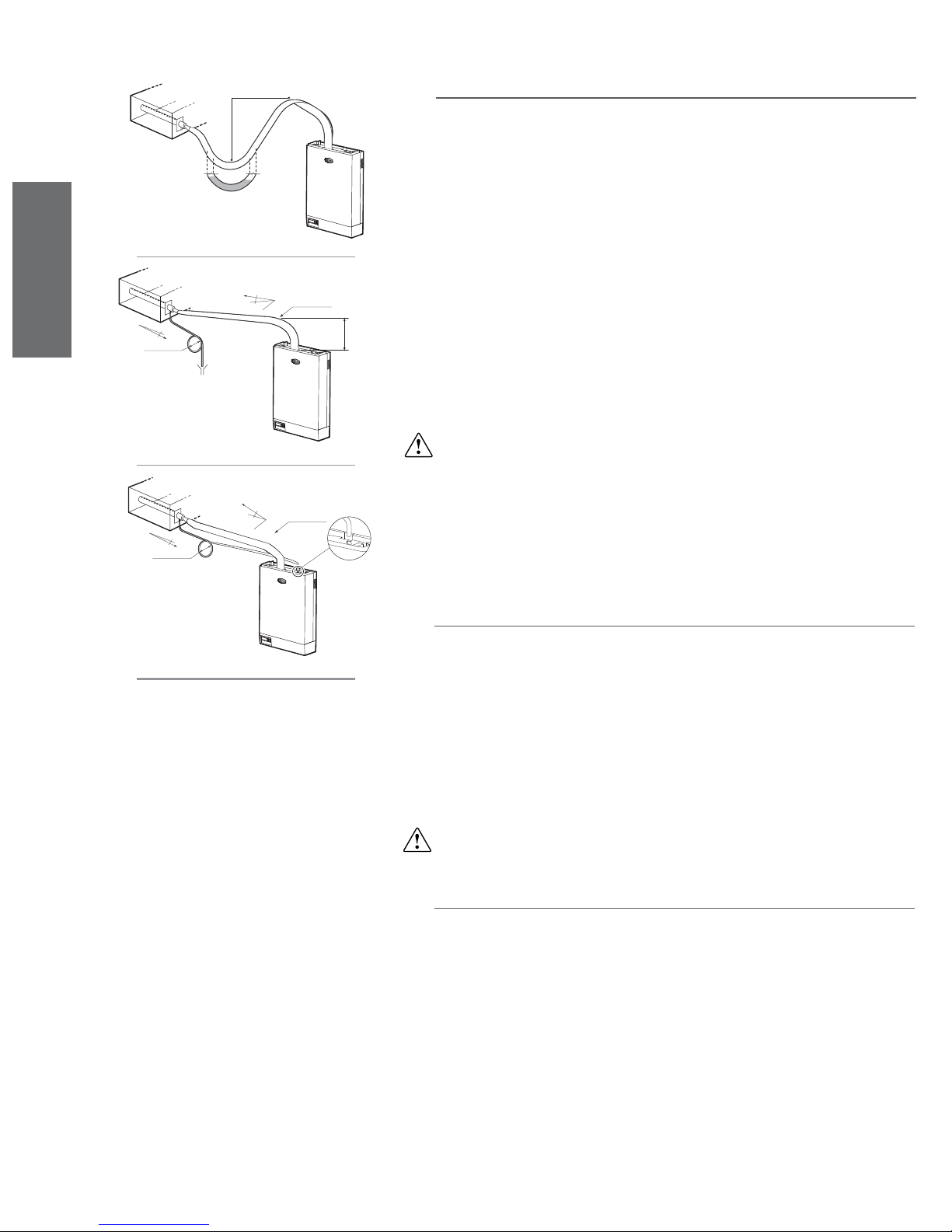
ENGLISH
>5°
D> 200mm
Fig. 8.g
>5°
NO
R> 300mm
H≤ 2m
8.6 Installation of the steam pipe
The connection between the humidifi er and distributor must be made using a suitable pipe, such as the
CAREL fl exible pipes. The use of incorrect pipe may lead to fragility and cracks and consequent steam
leaks.
The shape of the pipe must be such as to avoid the accumulation of condensate and consequent noise
(in the form of gurgling) and loss of effi ciency; the course of the pipe must exploit gravity to drain the
re-condensed steam back to the cylinder or the distributor.
Avoid the formation of pockets or traps where condensate may form; furthermore, ensure that the pipe
is not choked due to tight bends or twisting (see Fig. 8.g).
Fasten the ends of the pipe to the connections on the humidifi er and the steam distributor using screw
clamps, so that they do not come loose as a result of the temperature.
Depending on the position of the steam distributor, the course of the pipe may be one of the following:
1. upwards with a vertical section at least 300mm/11.8 inch in length, followed by a bend with a
minimum radius of 300 mm/11.8 inch, and fi nally a downward section with a constant slope of not
less than 5° (see Fig. 8.h);
2. for very short courses (less than 2 metres/7 feet), a curve with a minimum radius of 300mm/
11.8 inch followed by from an upward section with a slope of not less than 20° (see Fig. 8.i).
>5°
D>200mm
Fig. 8.h
>20°
Fig. 8.i
IMPORTANT WARNING: the length of the steam pipe should be less than 4 m/13.1 feet.
R>300mm
8.7 Installing the condensate return pipe
Due to the re-condensation of part of the steam produced, condensate forms in the steam conveyance
pipe and inside the distributor, which must be drained to avoid gurgling, and loss of effi ciency.
The condensate is drained by the effect of gravity with the help of a fl exible pipe suitable for this purpose. The use of an incorrect pipe can lead to fragility and cracks and consequent water leaks.
To avoid the non-condensed steam from being released through the condensate pipe, a trap must be
created by curling a part of the drain pipe.
The end of the condensate pipe can be connected to the nearest drain, with a minimum slope of 5° to
assist downfl ow (see Fig. 8.h).
If there is enough distance from the distributor, the hose can be introduced into the humidifi er through
the hole on the top of the unit, reaching the boiler supply tank (for 20-60kg/h units), or alternatively
connected to the special C fi tting supplied, to be tightened to the top of the humidifi er, so as to drain the
condensate from boiler supply tank (see Fig.. 8.i).
IMPORTANT WARNING: for correct functioning, the drain trap must be fi lled with water before starting
the humidifi er.
8.8 Checks
The following conditions represent the correct installation of the steam pipe:
• the position of the steam distributor conforms to that described in this chapter, the steam outlet pipe
points upwards and the distributor is inclined at least 2° upwards;
• the ends of the pipes are fastened with metal screw clamps;
• the curves in the pipe are quite wide (radius > 300 mm /11.8 inch) so as not to cause pinching or
choking;
• there are no pockets or traps in the steam pipe to avoid condensation;
• the courses of the steam pipe and the condensate pipe conform to those described in this chapter;
• the length of the steam pipe does not exceed 4 metres/13.1 feet;
• the slope of the steam pipe is suffi cient to drag the condensate (> 20° for the upward sections, > 5°
for the downward sections);
• the slope of the condensate pipe is at least 5° at each point;
• the condensate pipe features a drain trap (fi lled with water before start-up) to avoid the release of
steam.
40
heaterSteam +030222011 - rel. 2.1 - 21.05.2010
Page 41
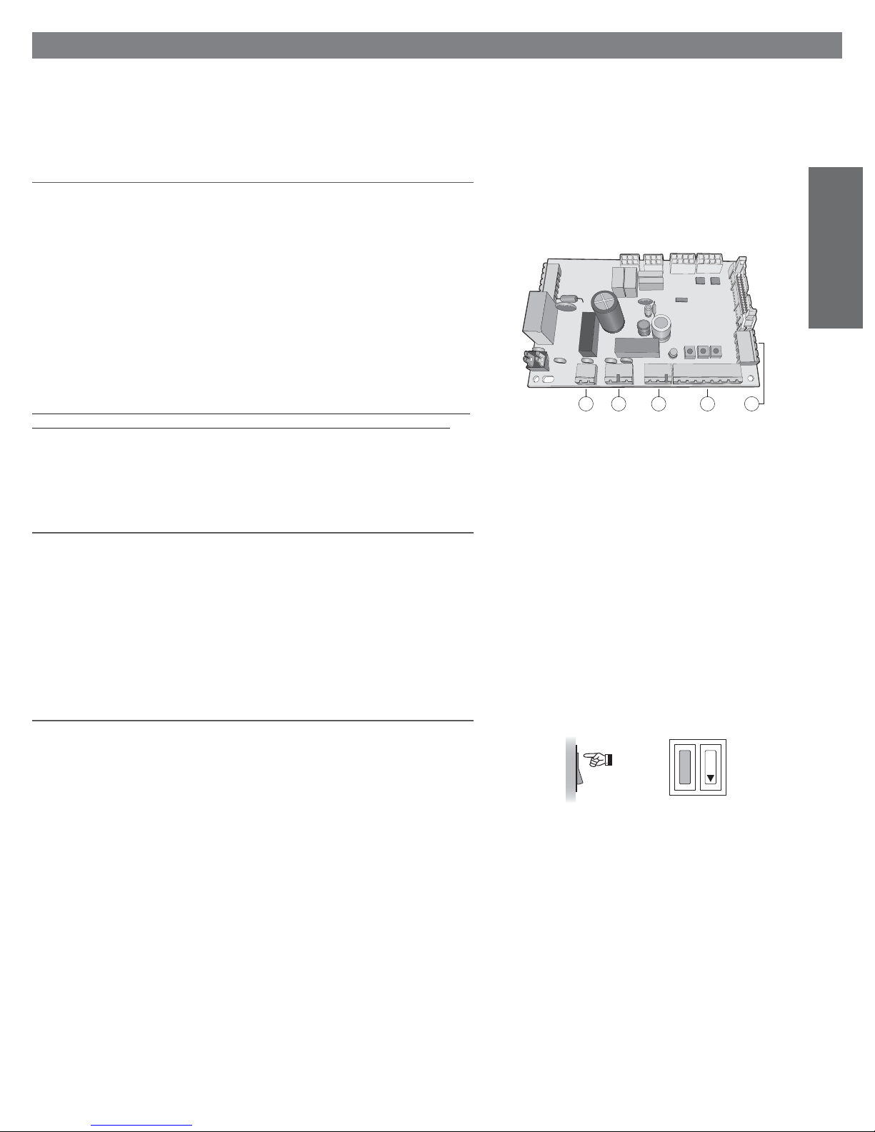
9. START-UP
IMPORTANT WARNING: on completion of the installation procedure, drain the supply pipe for around
30 minutes by passing water directly through the pipe and without introducing it into the humidifi er. This
will allow the elimination of any scoria and processing residues that may cause the formation of foam
during the boiling.
9.1 Preliminary checks
Before starting the humidifi er, check that:
• the water and electrical connections are made and the steam distribution system is confi gured according to the instructions contained herein;
• the shut-off tap for water into the humidifi er is open;
• the power fuses are installed and in tact;
• terminals 7I and 8I are connected by jumper or connected to the remote ON/OFF contact, and that
the latter is closed;
• the probes or the external control device are correctly connected (and that the ground of these
devices is electrically connected to the ground of the main control board);
• the steam outlet pipe is not choked;
• in the event of ducted humidifi cation, the operation of the humidifi er is slave to the operation of the
air fan (replacing or in series with the remote ON/OFF contact);
• the distributor condensate return pipe is installed and free;
• the drain pipe is correctly connected and free.
Before starting the humidifi er, check that it is in perfect condition, that there are no water leaks and that
the electrical parts are dry. Do not supply voltage if the humidifi er is damaged or even partially wet!
ENGLISH
1 2 3 4 5
Fig. 9.a
9.2 Removing the heating element centring spring (only for
three-phase models)
To prevent the elements in three-phase models hitting each other or against the internal wall of the
cylinder and thus damaging the appliance, due to vibrations or bumps during transport, the heating
elements are factory-fi tted with a centring spring, which has no function during the operation of the
appliance.
As the centring spring may hinder the removal of lime-scale from the elements and diminish the interval
between cleaning cycles, the spring should be removed before the initial start-up.
To do this, remove the cylinder by following the relative instructions (see Maintenance of the cylindercylinder).
9.3 Start-up
After having closed the power switch to the humidifi er, turn the appliance on by moving the rocker
switch (next to the DRAIN button) located in the bottom right of the frame, to the I position.
The start-up sequence is then initiated. This includes the initial phase, the autotest phase, and fi nally, the
actual operating phase.
According to the model of the humidifi er’s control module, the start-up sequence is signalled by the
lighting up of the LEDs on the control panel, as described in the following chapter.
ON
1
0
Fig. 9.b
heaterSteam +030222011 - rel. 2.1 - 21.05.2010
41
Page 42
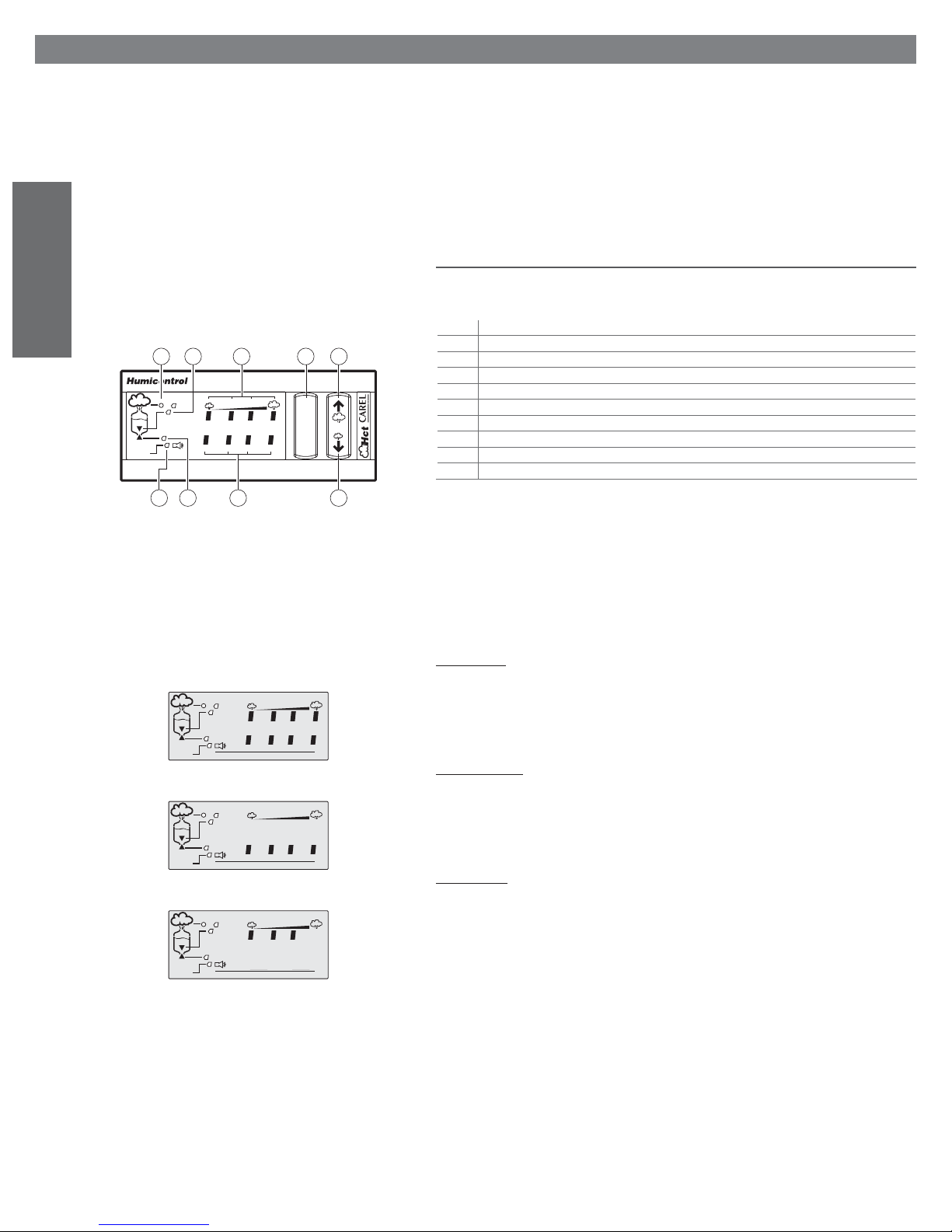
10. THE HUMIDIFIER CONTROLLER
Two types of electronic controller are available for the electric heater humidifi er (see CONTROL PRINCIPLES):
• Type C control module, with indication LEDs and ON/OFF action
This control provides control of the steam production capacity and ON/OFF control;
• Type H or T control module, with numeric LED display and modulating action
This control provides complete control of the steam production capacity, with optional dehumidifi cation function; it accepts signals from humidity probes or from external electronic devices with
proportional (or ON/OFF) control).
10.1 Type C control module, with indication LEDs and ON/OFF
action
ENGLISH
alarm
10.1.1 Front panel
n. description
1 reset button for the alarm relay (if the alarm is no longer active)
6
127 4
2 increase programmed steam production button
3 decrease programmed steam production button
4 set steam production bar graph (percentage
5 bar graph indicating any active alarms
30% 50% 75% 100%
1234
reset
6 LED indicating current steam production
7 LED indicating operation of drain electrovalve
8 LED indicating operation of the fi ll electrovalve
9 fl ashing LED indicating alarm relay activated
9
8
53
Fig. 10.a
The ON/OFF version allows the display and modifi cation only of the steam production parameter.
Table 10.a
The other functional parameters are factory set and cannot be modifi ed by the user (they can however
be accessed via serial line).
10.1.2 Start-up sequence
On starting-up the humidifi er, the start-up sequence occurs, signalled by the lighting up of the LEDs, as
described below.
1 - POWER ON
In this phase, lasting around one second, all the LEDs on the display light up.
30% 50% 75% 100%
alarm
1234
Fig. 10.b
2 - INITIALISATION
Duration around 4 seconds. The LEDs highlighted here all light up on the display.
30% 50% 75% 100%
alarm
1234
Fig. 10.c
30% 50% 75% 100%
alarm
1234
Fig. 10.d
3 - OPERATION
The humidifi er, if enabled performs the autotest, and then begins operation; the control module indicates, on the four-stage bar graph (30%; 50%; 75%; 100%), the set steam production and, in the event of
an alarm, the number on the corresponding bar code.
10.1.3 Display and control
Normally the panel shows the set steam production capacity, using the 4-stage bar graph (30%; 50%;
75%; 100%).
To change the set value press the and buttons. The change to the set production is stored
permanently.
42
heaterSteam +030222011 - rel. 2.1 - 21.05.2010
Page 43

10.1.4 Alarm indications
The lighting up of LED 9 (see Fig. 10.a) and a combination of the LEDs 5 indicates the presence of a
current alarm state; in the event of more than one alarms, the LEDs 5 light up in sequence, at 2 second
intervals.
At the same time, the control module activates the alarm relay (see ELECTRICAL CONNECTIONS).
To interpret the type of alarm, see ALARMS AND TROUBLESHOOTING.
The control module continues to indicate the alarm state (even if this is no longer active) until the reset
button is pressed; still active alarms can not be reset.
10.1.5 Manual drain command
In the fi rst 5 seconds from the start-up of the unit (during the autotest sequence: see Fig. 10.c), press the
and buttons at the same time. After 2 seconds the drain solenoid valve is activated and completely
empties the water contained in the cylinder. To stop the drain cycle, press the and buttons again.
10.1.6 Setting the steam production
The average steam production can be adjusted using a pseudo-modulating action, with the cyclical
activation of the remote-control switch and a programmable operating interval divided into four steps:
30%; 50%; 75%; 100% of the total time (this mode can not be applied in severe operating conditions
and without consequences on the noise level caused by the frequent activation of the remote-control
switch). To do this, use the and buttons, see Fig. 10.a.
10.2 Type H or T control module, numeric LED display,
modulating action
10.2.1 Front panel
n. description
1 button for accessing the more frequently used functional parameters (codes Px, dx); it also acts as a
reset button for the alarm relay (if the alarm is no longer active)
2 - displays the unit of measure of the value shown on the display;
- pressed for 2 seconds accesses the display/programming of the set point;
- if pressed together with button 1 for 5 seconds, accesses the routine for programming the confi guration parameters
3 while pressed, displays the value measured by the main probe (with ON/OFF control nothing is
displayed); in programming mode acts as a button to decrease the value or scroll back to the previous
parameter
4 - while pressed, displays the value measured by the limit probe (only if featured);
- in programming mode acts as a button to increase the value or scroll to the next parameter
5 - 2 1/2 digit display to indicate the numeric values and codes of any active alarms;
- during programming shows the codes of the parameters and their values
6 LED representing the decimal point
7 LED for multiplying by one thousand the value indicated on the display
8 LED indicating the activation of the dehumidifi cation relay
9 LED fl ashing indicating alarm relay activated
10 LED indicating current steam production
- if fl ashing indicates the pre-heating phase
11 LED indicating operation of the fi ll electrovalve
12 LED indicating operation of the drain electrovalve
Table 10.a
12
10
alarm
dehum. x1000
11 69
Fig. 10.e
13578
PRG
reset
SEL
24
ENGLISH
10.2.2 Start-up sequence
On starting-up the humidifi er, the start-up sequence occurs, signalled by the lighting up of the LEDs, as
described below.
1 - POWER ON
In this phase, lasting around a second, all the LEDs on the display light up.
2 - INITIALISATION
Duration around 4 seconds. The LEDs highlighted here all light up on the display.
3 - AUTOTEST PROCEDURE
see paragraph 2.8
4 - OPERATION
The humidifi er begins operation, and the control module indicates (see CONTROL PRINCIPLES) one of
the following options:
• steam production (in %) with slave control;
• the measurement of the main transducer with autonomous control;
• when the humidifi er is disabled, the 3 segments - - - light up in sequence.
In the event of an active alarm, the LED next to the ALARM marking lights up and the display shows the
corresponding code.
heaterSteam +030222011 - rel. 2.1 - 21.05.2010
dehum. x1000
alarm
Fig. 10.f
dehum. x1000
alarm
Fig. 10.g
dehum. x1000
alarm
Fig. 10.h
43
Page 44
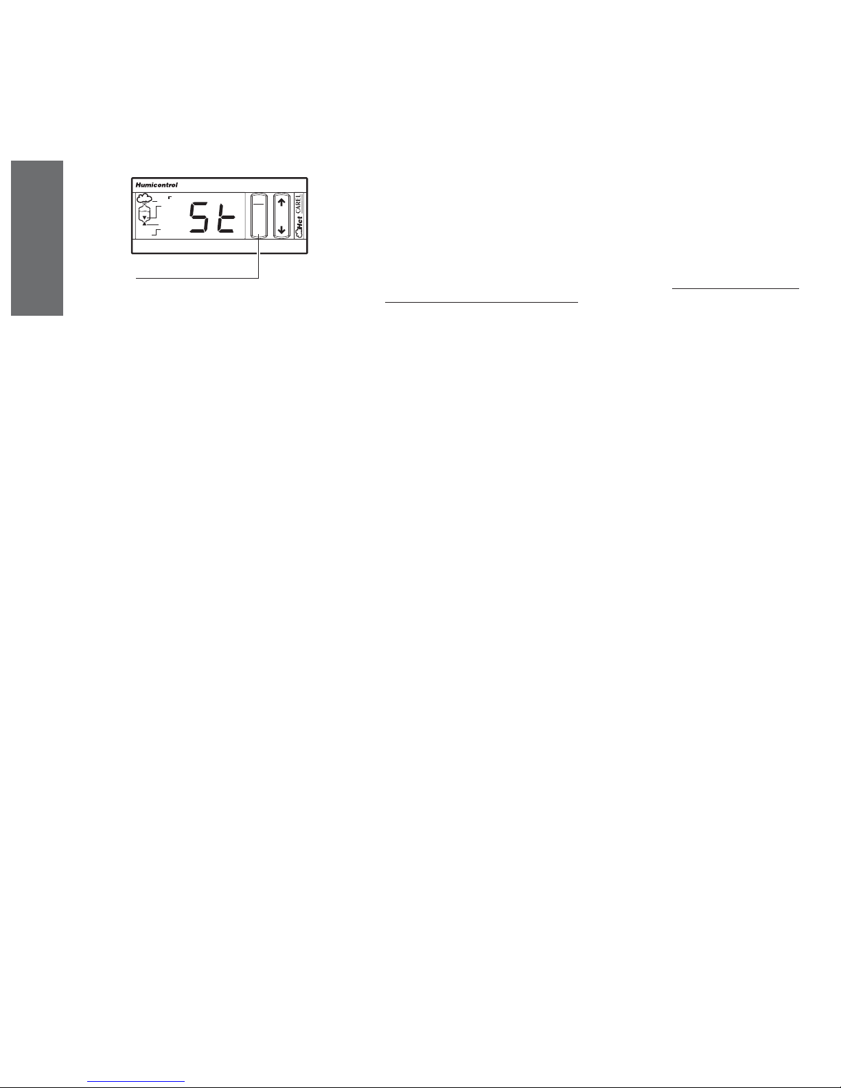
alarm
dehum. x1000
PRG
reset
SEL
10.2.3 Display
The panel shows the current functional parameter programmed (with the code C0, see Reading and
programming the confi guration parameters).
Normally this is:
• the measurement of probe no. 1 (ambient humidity or temperature), in appliances with autonomous
control;
• steam production in appliances with slave control.
Pressing the SEL button displays for one second the unit of measure of the measurement displayed.
Pressing the button shows the measurement of probe 1 (if fi tted), preceded for 1 second by the
corresponding unit of measure. The display is valid even in the event where the probe is not connected.
Pressing the button shows the measurement of probe 2 (if fi tted), preceded for 1 second by the
corresponding unit of measure. The display is valid even in the event where the probe is not connected.
To display the set point (main setting):
• press the SEL button for around 2 seconds, until St appears (see Fig. 10.i);
• on releasing the button, the unit of measure of the set point is displayed for 1 second, and fi nally the
current set value.
ENGLISH
press for around 2 s
Fgi. 10.i
Furthermore, the frequently-used functional parameters can also be displayed, that is those more
commonly used by the appliance: to do this, follow the instructions in: Reading and programming the
control parameters - reading the measurements.
10.2.4 Changing the set point
To change the set point (main control setting), follow the instructions in: Reading and programming the
set point.
10.2.5 Alarm indication
In the event of an alarm state, the LED 9 (see Fig. 10.a) starts fl ashing, while the display shows the
alphanumeric alarm code, alternating every 2 seconds with the programmed value of the functional
parameter.
If more than one alarm is indicated, the display shows all the corresponding codes in sequence, at 2
second intervals.
At the same time, the control module activates the alarm relay (see ELECTRICAL CONNECTIONS).
To interpret the type of alarm, refer to: ALARMS AND TROUBLESHOOTING. The control module will
continue to indicate the alarm state (even if it is no longer active) until the reset button is pressed; still
active alarm states can not be reset.
10.2.6 1. Total manual drain at SWITCH-ON
The total manual drain starts if keys and are kept pressed during the initial 5 seconds after switching
on heaterSteam. Once it starts, the keys can be released. The drain continues until either of the following
events occurs:
• the boiler is emptied;
• keys and are kept pressed again for at least 5 seconds: the drain stops.
44
heaterSteam +030222011 - rel. 2.1 - 21.05.2010
Page 45
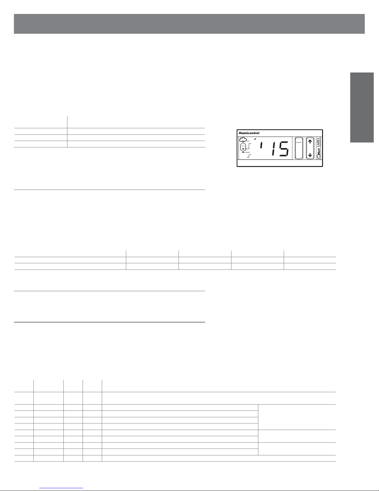
11. READING AND PROGRAMMING THE PARAMETERS
OF THE TYPE H OR T CONTROL MODULE
The numerical, confi guration and control panel parameters are grouped into three levels:
1. LEVEL 1 - set point, that is the value of the appliance’s main setting St, accessible directly via the
keypad for both reading and modifi cation;
2. LEVEL 2 - control parameters and measurements, that is the physical vales measured and the
functional parameters involving the control of the humidifi cation process; these too can be accessed
directly via the keypad for reading and modifi cation;
3. LEVEL 3 - confi guration parameters consisting of the data
needed to customise the control, according to the requirements of the humidifi er. These parameters
are can be accessed only by password, to prevent the unwanted modifi cation of the confi guration
and the humidifi er’s essential functions.
Each parameter is composed as follows:
code alphanumeric symbol appearing on the display corresponding to the parame-
range of variation limit values within which the parameter can be modifi ed
default value set in the factory for the parameter
unit of measure symbol displayed showing the unit of measure used for the parameter
Warning: the numerical values from 200 to 255 are displayed with the symbol / in the place of the
hundreds digit 2 (due to the specifi c constructive confi guration of the display).
Figure 11.a shows how the number 215 is displayed.
11.1 Reading and programming the set point
To read and/or change the set point, proceed as follows:
• press the SEL button for around 2 seconds, until St appears;
• on releasing the button, the unit of measure of the set point is displayed for 1 second, and fi nally the
current set value;
• to change the set point, press the and buttons, checking that the action is being performed on
the display;
• press the SEL or PRG button to confi rm the value displayed and conclude the programming of the set
point.
The characteristics and the range of variation of the set point are listed in Table 11.b.
type H control module % rH 50 0 P7
type T control module (for steam baths) °C/°fH 30/86 0 50/122
ter in question
dehum. x1000
Table 11.a
alarm
PRG
reset
SEL
Fig. 11.a
unit of measure default value minimum limit maximum limit
ENGLISH
Table 11.b
11.2 Display of SW release
The sw release is displayed any time that keys and PRG are pressed together and then released.
11.3 Reading and programming the control parameters - reading
the measurements
The control parameters represent the values relating to the process of ambient humidity (or temperature) control and are identifi ed by a code ranging between P0 and P9, according to the criteria described
in Table 11.c.
The readings are on the other hand the physical values measured by the transducers connected to the
control, depending on the model and the setting of the humidifi er, and the number of operating hours
from the previous reset; the measurements are identifi ed by a code ranging between d1 and d9 (see
Table 11.d).
Control parameters
code on
range of
display
variation
P0 10, ..,100 100 % maximum production; in the event of modulation disabled (b0=0), the production is always at 100% of the rated value, irrespective of
P1 2.0, .., 19.9 5.0 % rH humidifi cation differential can only be accessed in autonomous
P2 (P3), .., 100 100 % rH high humidity alarm threshold
P3 0, .., (P2) 0 % rH low humidity alarm threshold
P4 0, .., 100 1 min alarm delay (0*= 30 seconds)
P5 2, .., 100 10 % rH dehumidifi cation dead zone can only be accessed with dehumidifi cation
P6 2.0, .., 19.9 5.0 % rH humidifi cation differential
P7 (St), .., 100 100 % rH outlet set point can only be accessed in autonomous
P8 2.0, .., 19.9 5.0 % rH outlet differential
P9 0, .., 100 100 % rH high outlet humidity alarm threshold
heaterSteam +030222011 - rel. 2.1 - 21.05.2010
default unit of
measure
description
the value of the parameter
control (A0=2 or 3)
function enabled (b1=2 or 3)
control with outlet probe (A0=3)
Table 11.c
45
Page 46
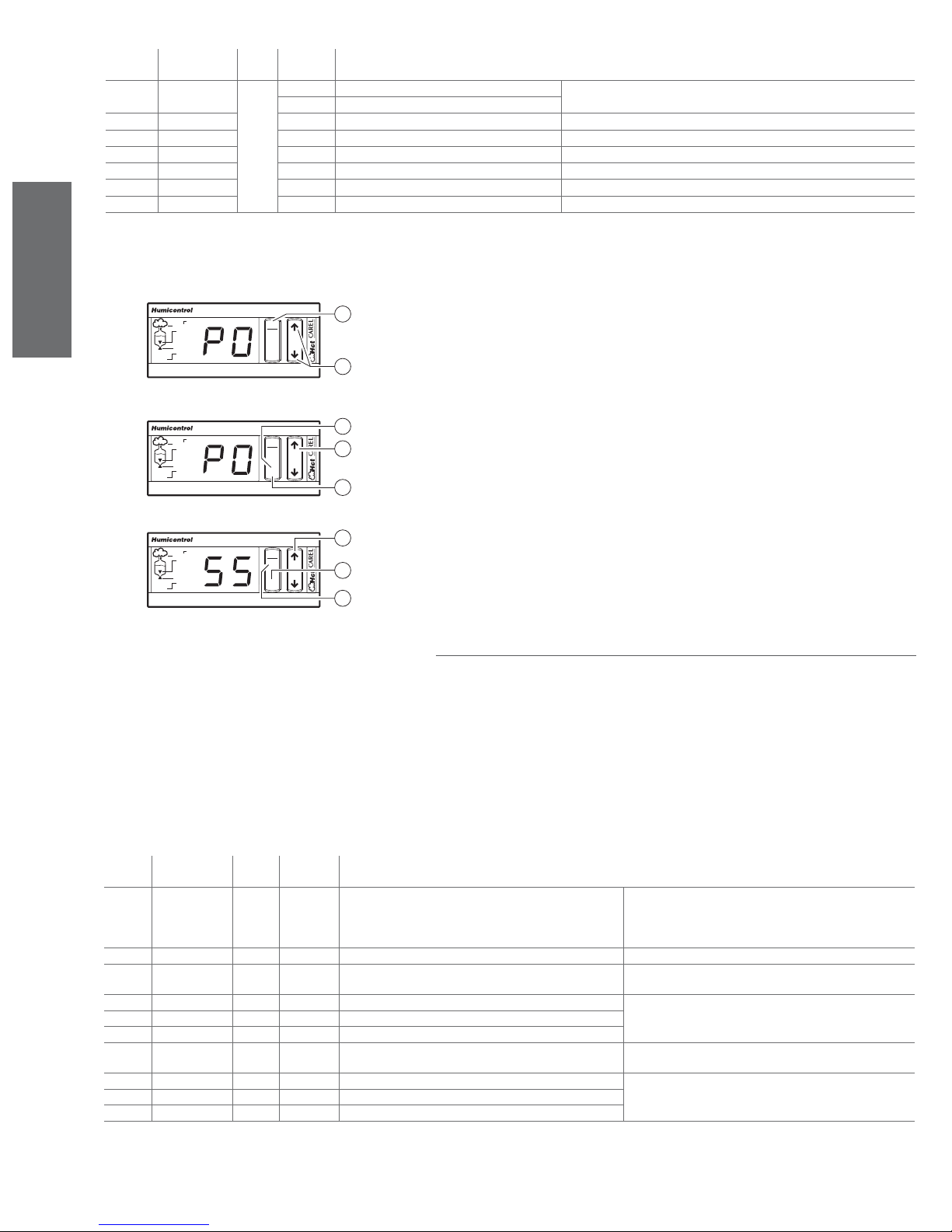
list of measurements
code on
display
d1 (1) 0, .., 100 read
range of
variation
default unit of
description
measure
% measurement signal from external regulator can only be accessed in slave or autonomous control (A0=1, 2 or 3)
only
% rH measurement from room probe
d2 0, .., 100 % rH measurement from outlet probe can only be accessed in autonomous control with outlet probe (A0=3)
d3 0.0, .., 199 kg/h steam production
d4 0, .., 19900 h hour counter
d5 0, .., 1500 µS/cm conductivity
d6 0, .., 100 °C water temperature can only be accessed with pre-heating function enabled (b1=1 or 3)
d9 0.0, .., 199 kg/h rated steam production
(1): in proportional operation (A0=1), d1 is expressed as a % of the working interval selected by A2; for
information on A0 and A2: see Table 11.e.
To display the control parameters and the measurements, proceed as follows:
1. Press the PRG button for around 5 seconds until the code P0 appears, representing the fi rst para-
ENGLISH
alarm
dehum. x1000
Fig. 11.c
PRG
reset
SEL
1
2
meter (see Fig. 11.c);
2. Press the or button to scroll cyclically through the Px and dx parameters, including the set point;
3. Press the SEL button to display the value of the selected parameter; the unit of measure of the
parameter is displayed for 1 second;
4. Press the PRG button to conclude the display phase.
To modify the control parameters (the measurements can only be read), proceed as follows:
1. Press the PRG button for around 5 seconds until the code P0 appears, representing the
fi rst parameter (see Fig. 11.d);
2. Press the or button to scroll cyclically through the Px and dx parameters, including the set
point;
3. Press the SEL button to display the value of the selected parameter; the unit of measure of the
parameter is displayed for 1 second;
alarm
dehum. x1000
Fig. 11.d
PRG
reset
SEL
4
5
3
4. Press the or button to modify the value; keeping one of the buttons pressed increases the
scrolling speed (see Fig. 11.e);
5. Press the SEL button to confi rm the new value displayed; the identifying code Px or dx
of the selected parameter will reappear;
6. Press repeatedly to scroll to next desired parameter and repeat steps 2 to 5;
7. Press the PRG button to permanently save the modifi cations and conclude the programming phase.
alarm
dehum. x1000
PRG
reset
SEL
7
8
6
Fig. 11.e
Table 11.d
11.4 Reading and programming the confi guration parameters
The confi guration parameters are used to set the operating mode of the controller, that is to assign the
humidifi er’s essential functions.
The confi guration parameters are divided into three groups:
• Parameters for confi guring standard operation (operating mode and types of probes), identifi ed by
codes from A0 to A9: see Table 11.f;
• Parameters for confi guring the operation of accessory devices, identifi ed by codes from b0 to b7:
see Table 11.g;
• Parameters for the setting the serial connections and remote control, identifi ed by codes from C0
to C7: see Table 11.i.
These parameters can be accessed only by password to prevent the unwanted modifi cation of the
confi guration.
Parameters for confi guring standard operation
code on
display
A0 0,.., 3 2 operating mode 0= ON/OFF command
A1 0, 1 0 unit of measure 0= °C, kg/h - 1= °F, lb/h
A2 0, .., 4 0 signal applied to room probe input autonomous control (A0=1,
A3 0, .., (A4) 0 % rH room probe minimum can only be accessed in autonomous control (A0=2 or 3)
A4 (A3), .., 255 * 100 % rH room probe maximum
A5 -10.0, ..., 10.0 0 % rH room probe calibration
A6 0, .., 4 0 signal applied to the outlet probe input can only be accessed in
A7 0, .., (A8) 0 % rH outlet probe minimum can only be accessed in autonomous control with outlet probe
A8 (A7), .., 100 100 % rH outlet probe maximum
A9 -10.0, ..., 10.0 0 % rH outlet probe calibration
range of
variation
default unit of
measure
description
2 or 3)
autonomous control with outlet probe (A0=3)
*: see WARNING to side of Fig. 11.a.
1= slave control
2= autonomous cont. with room probe
3= autonomous cont. with room probe and outlet probe
0= 0/1 V - 1= 0/10 V - 2= 2/10 V - 3= 0/20 mA
4= 4/20 mA
0= 0/1 V - 1= 0/10 V - 2= 2/10 V - 3= 0/20 mA
4=4/20 mA
(A0=3)
Table 11.f
46
heaterSteam +030222011 - rel. 2.1 - 21.05.2010
Page 47
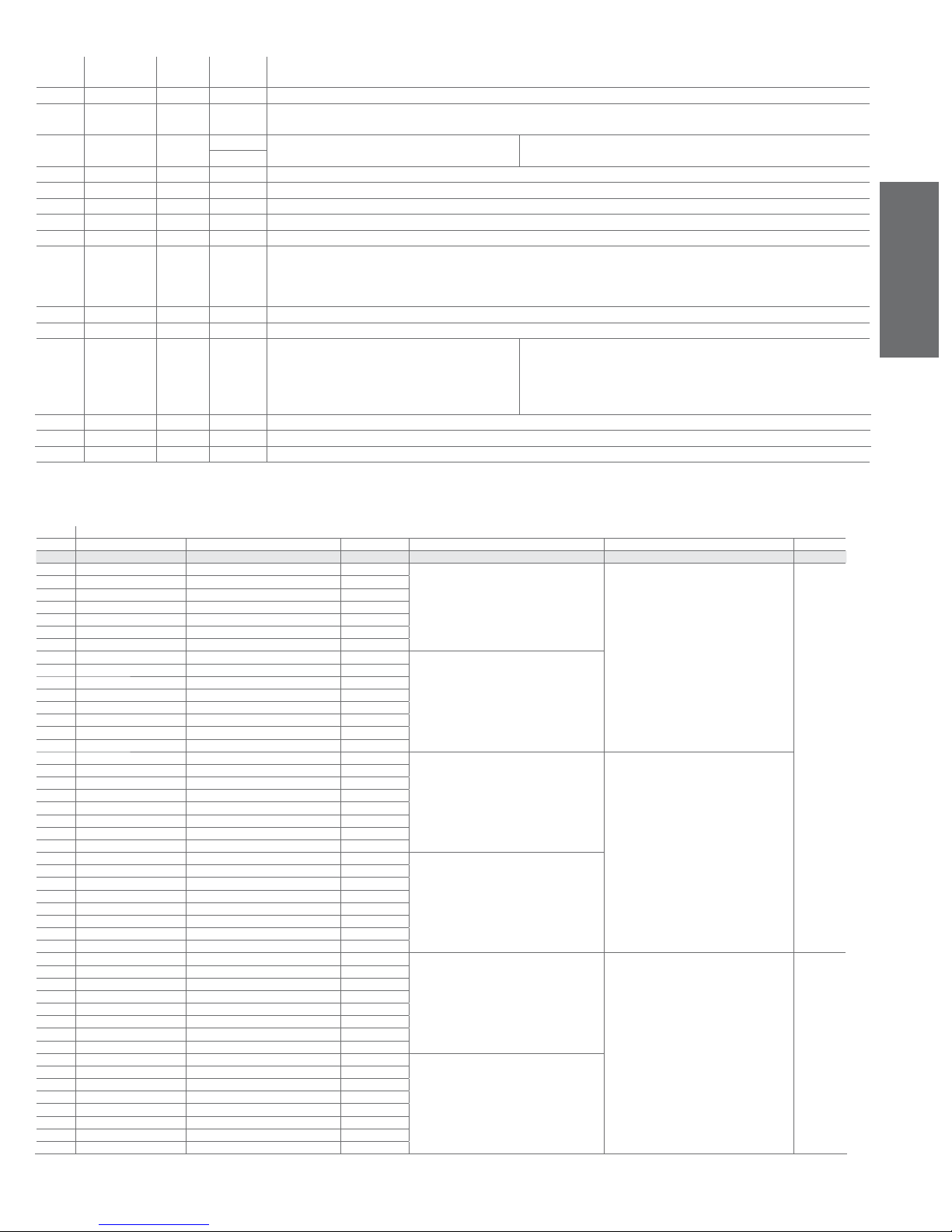
Parameters for confi guring the operation of accessory devices
code on
display
range of
variation
default unit of
measure
description
b0 0 to 199 ** s period of modulation (if set to 0 modulation is disabled)
b1 0 to 63 0 The user is allowed to defi ne whether the alarm relay must be energized with or without alarm(s). This can be accomplished by setting
the parameter b1 as shown in table 11.h
b2 2 to 19.9 3.0 % start pre-heating offset ( referred to set point) can only be accessed with pre-heating function enabled (b1=1 or 3)
% rH
b3 70 to 90 80 °C pre-heating temperature
b4 0 to 2000 0 µS/cm supply water conductivity: if set to 0 the conductivity is measured automatically, otherwise, the set value is used
b5 0 to 2000 1250 µS/cm conductivity pre-alarm threshold (displayed as 1
2)
b6 0 to 2000 1500 µS/cm conductivity alarm threshold (displayed as 15)
b7 0 to 100 50 % control of the foam detection threshold (if set to 0 foam detection is disabled)
b8 1 to 50 depen-
ding
maximum number of evaporation cycles between two drain cycles for dilution
step:1
on the
model.
b9 0 to 100 0 min minimum time for passing from 0 to 100% of steam production
bA 20 to 100 100 % percentage reduction in the duration of the water fi ll time
bb -19,9 to 19,9 0 % steam production value (step 0.1%) allows the user to “adjust” the value displayed by parameter d3, if there is a
system available for measuring the difference between the value displayed d3
and the actual steam production.
Example:
d3= 10 kg/h and bb= +10% changes d3 to 11 kg/h (= 10 kg/h + 10%)
bC 1...199 3 99 automatic total drain for inactivity (see par. 11.8)
bD 0...190 100% % user-adjustable duration of dilution drain (see par. 11.9)
bE 5 to 199 199 s duration of the fi ll cycle in PWM mode
Table 11.g
**: il valore di default dipende dalla taglia dell’umidifi catore.
Values for parameter b1
b1 preheating dehumidifi cation request warning “cl” cumulative alarm relay energized when… automatic total drain for inactivity autotest
def. 0 OFF OFF ON alarms present ON ON
1ON OFF ON
2 OFF ON ON
3ON ON ON
4 OFF OFF OFF
5ON OFF OFF
6 OFF ON OFF
7ON ON OFF
8OFF OFF ON
9ON OFF ON
10 O FF ON O N
11 ON ON ON
12 OFF OFF OFF
13 ON OFF OFF
14 O FF ON OF F
15 ON ON OFF
16 OFF OFF ON
17 ON OFF ON
18 O FF ON O N
19 ON ON ON
20 OFF OFF OFF
21 ON OFF OFF
22 OFF ON OFF
23 ON ON OFF
24 OFF OFF ON
25 ON OFF ON
26 OFF ON ON
27 ON ON ON
28 OFF OFF OFF
29 ON OFF OFF
30 OFF ON OFF
31 ON ON OFF
32 OFF OFF ON
33 ON OFF ON
34 OFF ON ON
35 ON ON ON
36 OFF OFF OFF
37 ON OFF OFF
38 OFF ON OFF
39 ON ON OFF
40 OFF OFF ON
41 ON OFF ON
42 OFF ON ON
43 ON ON ON
44 OFF OFF OFF
45 ON OFF OFF
46 OFF ON OFF
47 ON ON OFF
functions
alarms present
ON
alarms absent
ON
alarms present
OFF
alarms absent
alarms present
ON OFF
alarms absent
ENGLISH
heaterSteam +030222011 - rel. 2.1 - 21.05.2010
47
Page 48
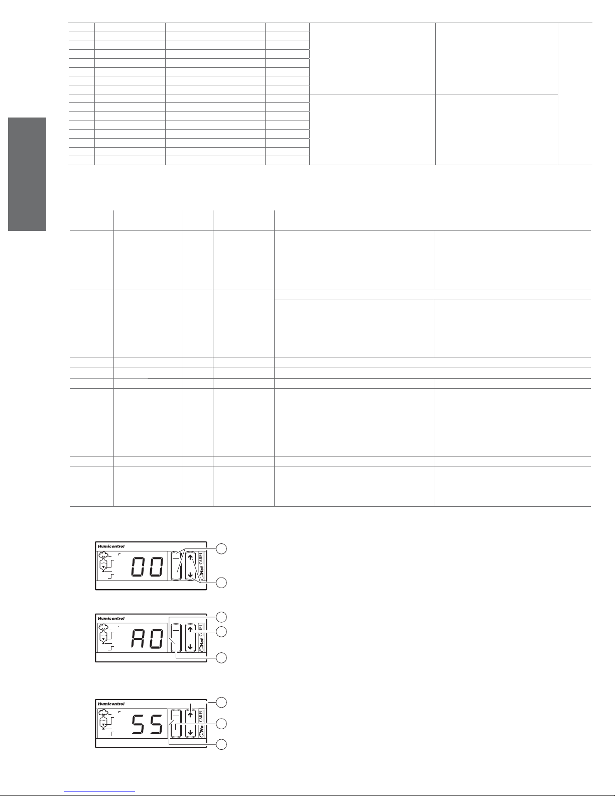
48 OFF OFF ON
49 ON OFF ON
50 OFF ON ON
51 ON ON ON
52 OFF OFF OFF
53 ON OFF OFF
54 OFF ON OFF
55 ON ON OFF
56 OFF OFF ON
57 ON OFF ON
58 OFF ON ON
59 ON ON ON
60 OFF OFF OFF
61 ON OFF OFF
62 OFF ON OFF
63 ON ON OFF
alarms present OFF
OFF
alarms absent OFF
Table 11.h
ENGLISH
code on
range of variation default unit of measure description
Parameters for setting the serial connections and remote control
display
C0 1...6 1 normally displayed value 1= room probe measurement
2= outlet probe measurement
3= steam production
4= hour counter
5= conductivity
6= water temperature
C1 0...4 4 enable keypad and remote control
keypad:
0= reading of all parameters, ( modifi cation of C1 only)
1= reading and modifi cation of all parameters
2= reading of all parameters, (modifi cation of C1 only)
3= reading and modifi cation of all parameters
4= reading and modifi cation of all parameters
remote control:
reading and modifi cation of parameters P, d and St
reading and modifi cation of parameters P, d and St
reading of parameters P, d and St
reading of parameters P, d and St
reading and modifi cation of all parameters
C2 0...99 0 Code for enabling remote control
C3 0...199 1 Serial address
C4 0...3 3 baud-rate 0=1200 1=2400 2=4800 3=9600
C5 0...11 0 frame
0= 8,N,2
1= 8,N,1
2= 8,E,2
3= 8,E,1
4= 8,O,2
5= 8,O,1
( character bits, parity, stop bits)
6= 7,N,2
7= 7,N,1
8= 7,E,2
9= 7,E,1
10= 7,O,2
11= 7,O,1
C6 0...199 0 ms serial reply send delay
C7 0...3 0 graphic terminal confi guration in cases 1,2,3 the OFF
command is forced on start-up
0= standard terminal
1= terminal with ON/OFF command
2=t erm. with ON/OFF and room probe
3= term. with ON/OFF and outlet probe
Table 11.i
dehum. x1000
alarm
PRG
reset
SEL
Fig. 11.j
dehum. x1000
alarm
PRG
reset
SEL
Fig. 11.k
dehum. x1000
alarm
PRG
reset
SEL
Fig. 11.l
1
To read or modify the confi guration parameters, proceed as follows:
1. Press the SEL and PRG buttons together for around 5 seconds, until the code 00 appears,
requiring the password to be entered (see Fig. 11.j);
2
3
4
2. Press the or button until the password value is reached (number 77);
3. Press the SEL button to confi rm the password. If the password is not correct, the programming
phase is terminated, otherwise A0 is displayed (see Fig. 11.e);
4. Press the or button to scroll cyclically through the Ax, bx and Cx parameters, including the set
point;
5
5. Press the SEL button to display the value of the selected parameter; the unit of measure of the
parameter is displayed for 1 second;
6. Press the or button to modify the value (keeping one of the buttons pressed increases the
scrolling speed);
6
7. Press the SEL button to confi rm the value displayed; the identifying code Ax, bx or Cx of the selected
parameter reappears;
7
8. Display and modify any other parameters, repeating steps 4 to 7;
9. Press the PRG button to permanently save the modifi cations and conclude the programming phase.
8
48
heaterSteam +030222011 - rel. 2.1 - 21.05.2010
Page 49
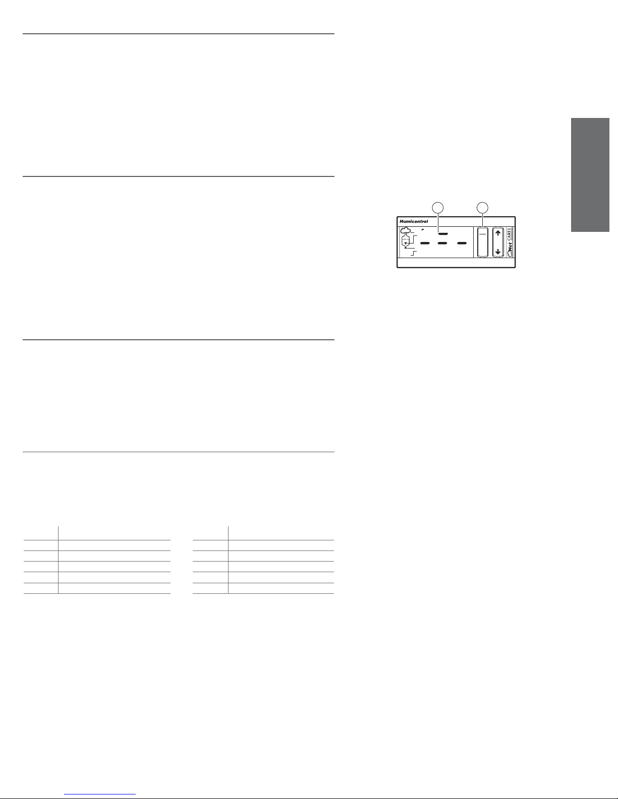
11.4 Validity of the modifi cations to the parameters
The modifi cations made to the parameters normally take effect when confi rmed with the SEL button,
and are saved permanently with the PRG button. For some parameters relating to the serial connection,
the value will only take effect only the next time the unit is switched on. During the programming phase,
5 seconds after the last button is released, the display begins fl ashing (to remind the user that he is in
programming phase). Sixty seconds after the last button is released, if the value of a parameter is being
displayed, any modifi cations are ignored and the display returns to the parameter’s identifying code. After a further 5 seconds, the display begins fl ashing again, and after 60 seconds the programming phase
is terminated and the parameters return to the values previous to the programming phase. If, on the
other hand, the parameter’s identifying code is being displayed, the programming phase is terminated
directly after 60 seconds (time out).
11.5 Recalling the default parameters (factory settings)
The default values can be recalled only on start-up, and in the following way:
• in the fi rst 5 seconds from start-up (while the three dashes are displayed), press the PRG button until
the upper dash in the centre fl ashes, as indicated in the Figure;
• release the PRG button within 3 seconds to confi rm the recall and permanent saving of the default
parameters; to confi rm the saving of the values, the upper dash will stay on for 2 seconds (as
displayed in Fig. 11.n);
• the operation is not effected if the PRG button is pressed for more than 3 seconds, until the upper
dash disappears.
alarm
1 2
dehum. x1000
PRG
ENGLISH
reset
SEL
Recalling the default parameters does not change the parameter relating to the unit of measure
(A1), it is thus recommended to check and if necessary select and save the unit of measure as required,
and then recall the default parameters. In this way the default values will automatically be converted.
11.6 Resetting the hour counter
To reset the hour counter (parameter d4), proceed as follows:
• press the PRG button for 5 seconds, until the code P0 is displayed, indicating the fi rst modifi able
parameter; using the and buttons, scroll the parameters until d4 is displayed;
• press the SEL button to display the value of the hour counter (preceded for 1 second by the unit of
measure);
• press the and buttons together for 5 seconds until the value is set to zero, preceded by a brief
fl ash.
11.7 Displaying and modifying the unit of measure
The unit of measure of some parameters depends on the type of control and the programming.
Displaying the unit of measure can then avoid incorrect interpretation. In the case of non-dimensional
measurements, the unit of measure is not displayed. It is also possible to use imperial rather than standard units of measure (parameter A1). For the procedure to be followed please refer to: Programming:
accessing type A, b and C parameters.
The two digits on the right are used to display the unit of measure:
display unit of measure display unit of measure
°C temperature in degrees centigrade
°F temper. in degrees Fahrenheit
rH relative humidity in %
Pr steam production in kg/h
Lb steam production in pounds/h
Table 11.o Table 11.p
M” time in seconds
M’ time in minutes
h time in hours
uS conductivity mS/cm
OO percent
Fig. 11.n
heaterSteam +030222011 - rel. 2.1 - 21.05.2010
49
Page 50

ENGLISH
11.8 Automatic total drain for inactivity
For hygienic reasons it is recommendable to empty the boiler not to have stagnant water inside in case
there isn’t any humidifi cation request for a long time.
In UR*H* and UR*T* the user can set the automatic total drain for inactivity as follows (read the remarks
below for UR*C*):
• The drain for inactivity is active by default. To disable it, simply go to parameter “b1” and operate as
described in the table in chapter 11.4;
• Vice-versa, if the drain for inactivity has been disabled, to enable it go to parameter “b1” and operate
as described in the table in chapter 11.4 and fi x the maximum inactivity period through the parameter
bC.
The automatic total drain for inactivity is enabled by default and the max. allowable default inactivity
period is 3 days, which means that the boiler is emptied automatically after heaterSteam has been on for
at least 3 days without humidifi cation request.
Parameter bC:
Range 1 to 199 days
Default 3 days
Step 1 day
Remarks heaterSteam must be left on in order to empty the boiler;
UR*H* and UR*T*: the display shows “idr” during the automatic total drain for
inactivity;
UR*C*: the automatic total drain for inactivity is enabled by default and the
boiler is emptied after 2 days of inactivity (fi xed default) but neither b1 nor bC
can be edited.
11.9 User-adjustable duration of dilution drain
The duration of the dilution drain can be adjusted through the new user parameter bD which defi nes the
new duration as a % of the internally set default duration: new duration= default duration x bD / 100.
Example: if the internally set duration 10 s and bD= 50%, then the new duration= 10 s x 50 / 100= 5 s.
Parameter bD:
Range
Default
Step
Remarks
0 to 190 % (0 % disables the dilution drains. WARNING: READ REMARKS
BELOW!)
100 %;
10 %.
bD= 0 % means that dilution drains are NOT DONE at all. WARNING:
RISK OF FOAM/CORROSION as the internal conductivity will increase. We
recommend to set bD= 0 after a very careful evaluation of the water quality
and consequences.
bD= 100 % means that the default duration will be used
bD< 100 % means that the duration is < default duration: less fresh water
is introduced after the drain thus reducing its negative impact on the steam
production (good for high precision applications), but the drain valve will
open more frequently in order to control the internal conductivity (decreasing lifetime). WARNING: RISK OF FOAM IN CASE bD IS TOO SMALL IN
RELATION THE WATER QUALITY
bD> 100 % means that the duration is > default duration: to be used for
diluting strongly the internal water when facing big foam and/or corrosion
problems. Steam fl ow will be negatively affected because of the larger
amount of fresh water introduced after the drain;
Choice of bD for a high-precision control of %rH: bD should be decreased
as much as possible, yet avoiding foam/corrosion. Choice procedure: trialand-error on fi eld
11.10 User-adjustable max. allowed no. of evaporation cycles
between 2 dilution drains
The no. of evaporation cycles between 2 subsequent dilution drains is internally calculated, but, through
the new parameter b8, the user is allowed to specify the max. allowed no. of evaporation cycles between
2 dilution drains. This means that the next diluition drain is done before the end of the b8 evaporation
cycle following the last diluition drain and NOT AFTER the b8-th evaporation cycle.
Parameter b8:
Range
Default
Step 1
50
1 to 50
depends on the model
heaterSteam +030222011 - rel. 2.1 - 21.05.2010
Page 51

11.11 Reduced fi lls to restore water level after evaporation
When, during the steam production, the upper fl oater switches because the water level has decreased, a
fi ll starts for restoring the water level.
The duration of the fi ll can be decreased through the new user parameter bA which defi nes the new
duration as a % of the internally set default duration: new duration= default duration x bA / 100. Note
that, regardless the value entered into bA, the water level will be always restored up to the upper fl oater.
Parameter bA:
Range 20 to 100 %
Default 100 %
Step 10 %
Remarks
bA= 100 % means that the default duration will be used
bA< 100 % means that the duration is < default duration: a smaller amount
of fresh water is introduced into the cylinder, thus with a smaller impact on
the steam production (good for high precision applications); on the other side,
however, the fi ll valve will open more frequently
11.12 PW M fi lls after dilution and high-level/foam drains
After a dilution or high-level/foam drain, water is fi lled into to restore the water level up to the upper
fl oater.
The fi lled fresh water disturbs the steam production because it decreases the average temperature of
the water inside the boiler: in order to reduce the negative infl uence of the fresh water on the steam
production, the user can enable the PWM fi lls after the dilution and high-level/foam drain.
PWM fi lls work as follows:
1. the mass of fresh water required to restore the water level is divided into smaller masses of fresh
water;
2. by keeping the partial fi lls as farther apart as possible from each other, each partial mass of fresh
water is given the maximum possible time for heating up before the next one arrives, thus reducing
the effect of the fresh water on the steam production.
The duration of each fi ll can be defi ned in seconds by the new user parameter bE:
Range 5 to 199 seconds
Default seconds, which corresponds to one single fi ll, i.e. no PWM fi lls, because a 199s fi ll
Step 1 second
is long enough to restore alone the water level
ENGLISH
heaterSteam +030222011 - rel. 2.1 - 21.05.2010
51
Page 52
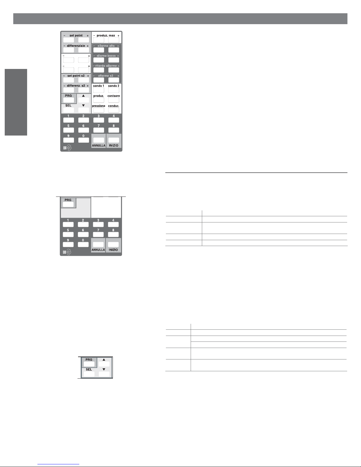
ENGLISH
12. THE REMOTE CONTROL (OPTIONAL ACCESSORY)
The remote control is an optional accessory and can only be used on humidifi ers with type H or T
control module (modulating).
It is available in two versions:
z. neutra deum.
differenz. deum.
Fig. 12.a
• TELURI000 with buttons marked in Italian;
• TELURE000 with buttons marked in English.
The infra-red remote control can command the call-up and display on the control module (see THE HUMIDIFIER CONTROLLER) of the humidifi er’s parameters, which, if necessary, can be modifi ed remotely.
Furthermore, the remote control simplifi es access to the main parameters, by pressing the corresponding marked buttons, avoiding the code search phase.
The remote control will operate at up to a distance of 3 metres, and can be used with all appliances in
the heaterSteam family.
In the event where there is more than one humidifi er within the remote control’s operating range, the
appliance to be operated can be determined by assigning each control module an individual access code
(parameter C2).
Acting on the value of parameter C1 (see Reading and programming the confi guration parameters)
allows the parameters that can be read or modifi ed using the remote control to be selected.
The standard value of C1 (default setting: C1=0) allows access to and modifi cation of type P and d
parameters and the set point only.
12.1 Description of the remote control
The buttons can be divided into three groups, according to their function.
Fig. 12.b
Fig. 12.c
12.1.1 Buttons for activating/deactivating the remote control
Allow the activation or deactivation of the remote control, saving the values associated with the parameters where necessary (see Fig. 12.b).
button function
START enables the use of the remote control
PRG concludes the programming, saving the values attributed to the parameters where
CANCEL cancels any modifi cations
number buttons set the access code to the parameters
necessary
12.1.2 Buttons for modifying the main parameters (direct access buttons)
The more-frequently used parameters are indicated directly on the remote control, grouped into areas of
different colours according to the function. Each modifi able parameter has a button with the + sign and
one with the - sign to increase or decrease the value.
The buttons without + or - signs only allow the display of the associated value on the control module.
12.1.3 Buttons for the remote control of the control module keypad
The section highlighted in green/blue on the remote control (see Fig. 12.c) reproduces the buttons on
the instrument and allows the same operations to be performed remotely; see Reading and
programming the parameters of the type H or T control module.
button function
PRG permanently saves the values and exits the programming phase
SEL - displays the unit of measure and the value of the selected parameter
- confi rms the modifi ed value and displays the parameter code
scrolls from one parameter to the next increases the value on the display during the setting
of the parameters
scrolls from one parameter to the previous decreases the value on the display during the
setting of the parameters
52
heaterSteam +030222011 - rel. 2.1 - 21.05.2010
Page 53
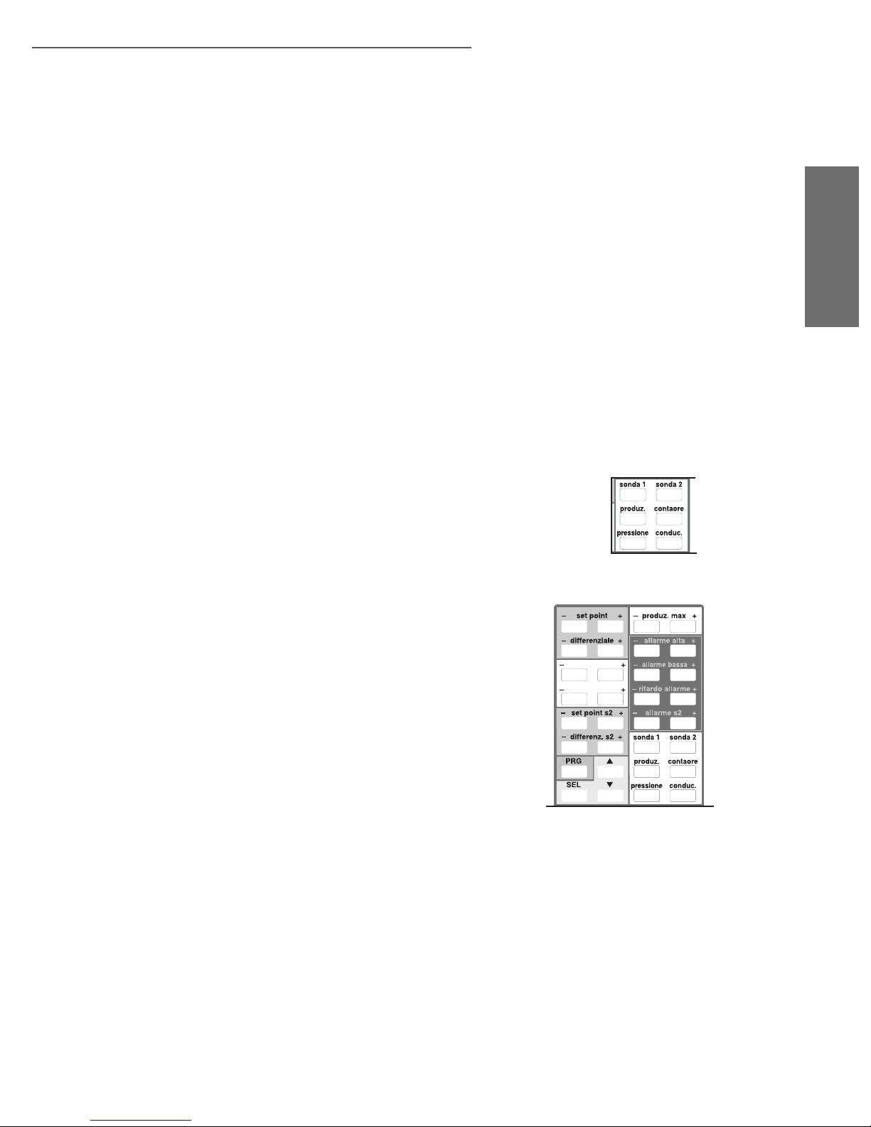
12.2 Programming from the remote control
To activate or deactivate the access code to use the remote control, enter into the control module confi guration mode using password 77 (see Reading and programming the confi guration parameters).
Assigning parameter C2 a value other than 0 (from 01 to 99), activates this number as the access code
that must be entered each time the remote control is used to program that unit.
Obviously, in installations with more than one unit, it is recommended to use a different code for each
unit.
Setting parameter C2 back to 0 means the remote control can be used without requiring the access
code.
When not in programming phase, the SEL (limited to the display of the unit of measure), PRG (limited
to the function of alarm reset) and the display-only buttons are always active.
12.2.1 Enabling the control for receiving without requiring access code (C2= 0)
Exit the programming phase if necessary, press the START button to enable the remote control; the
humidifi er’s control module will show the code for the fi st accessible parameter.
12.2.2 Enabling the control for receiving with access code required (C20)
Exit the programming phase if necessary, press the START button to enable the remote control.
All the units located within the operating range of the remote control will display their own access code.
To access the programming/reading routine, use the numeric keypad (Fig. 12.b) to enter the access code
for the machine to be operated on. Any zeroes must be included (e.g..: if the display shows 05, press the
0 and then the 5 button).
If the code is correct, the fi rst accessible parameter is displayed.
12.2.3 Reading the measurements
To directly display one of the measurements featured, press the corresponding button (Fig. 12.d) twice.
12.2.4 Modifying the main parameters (with specifi c button)
With reference to Fig. 12.e:
• press either the + or - button corresponding to the parameter to be modifi ed; the display shows the
parameter code;
• press the SEL button again to display the value;
• then press the + or - button to increase or decrease the value.
The values in the memory of the control module will automatically be modifi ed on exiting the programming phase.
ENGLISH
Fig. 12.d
z. neutra deum.
differenz. deum.
12.2.5 Modifying the main parameters (without specifi c button)
The parameters without a specifi c button can also be modifi ed, proceeding as follows:
• perform the operations for the enabling of the remote control;
• press the or button until the code of the required parameter is displayed;
• press the SEL button to display its value; then press or again to increase or decrease the value;
fi nally, press SEL to temporarily confi rm the new value;
• to modify other parameters, repeat the same operations.
heaterSteam +030222011 - rel. 2.1 - 21.05.2010
Fig. 12.e
53
Page 54

ENGLISH
12.3 Exiting the programming phase
To exit the programming phase and save the modifi cations made to the parameters, press the PRG
button.
To exit without saving the modifi cations, press the CANCEL button.
To exit the programming phase without confi rming the modifi cations made:
• do not press any button for 60 seconds, if the parameter code is displayed;
• do not press any button for 120 seconds, if the value of the parameter is displayed.
12.4 Table of remote control technical specifi cations
type description
power supply 2 (two) 1.5V mini alkaline batteries
(type UM-4 AAA, IEC R03)
case plastic
dimensions (mm) 60 x 160 x 18
storage temperature (°C)(°fH) -25T70 / -13T158
operating temperature (°C)(°fH) 0T40 / 32T104
type of transmission infra-red
weight (g)(lbs) 80 / 0.17(without batteries)
Table 12.a
54
heaterSteam +030222011 - rel. 2.1 - 21.05.2010
Page 55
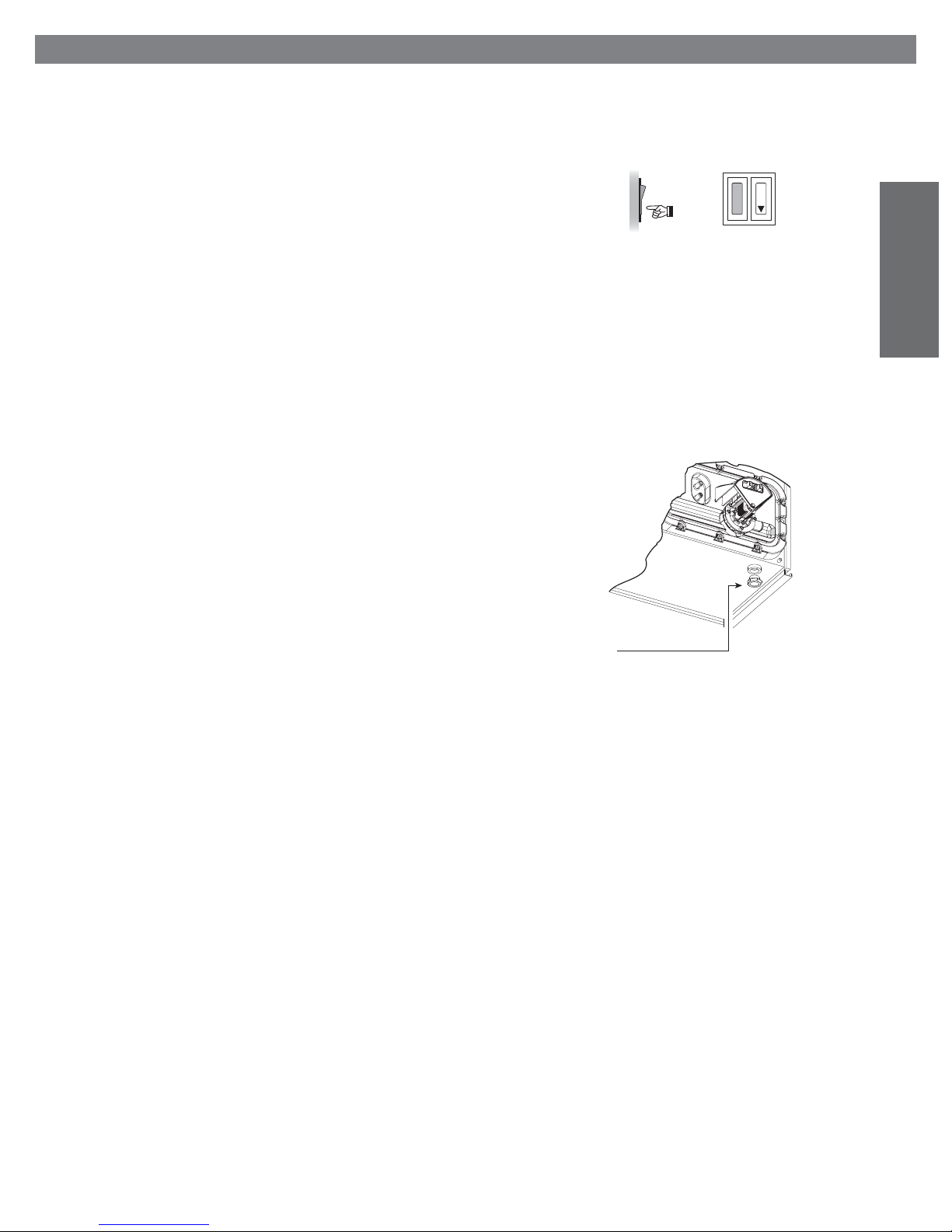
13. SHUTTING DOWN THE UNIT
When shutting down the unit at the end of the season or for maintenance on the electrical parts and/or
plumbing, the humidifi er should be put out of operation.
The water should not be emptied from the cylinder before shutting down the humidifi er to avoid
the hardening of the deposits contained in the cylinder and thus making them more diffi cult to remove.
Follow the instructions below (safety procedure):
• open the disconnecting switch on the power line to the humidifi er;
• open the rocker switch in the lower right of the frame, (see Fig. 13.a) checking that the display on the
control module is off;
• close the shut-off tap for the water supply to the humidifi er.
If the cylinder needs to be emptied when shutting down to remove the deposits, before switching off
power to the unit, press the DRAIN rocker switch, thus forcing the drain pump electrovalve to open,
keeping it in this position manually until the water is completely emptied (see Fig. 13.b).
In the event of malfunctioning of the drain pump electrovalve/ drain pump, the cylinder can be emptied
manually, as following:
• humidifi ers up to 10kg/h (22 lbr/h): by removing the connection pipe from the level control
housing spigot and slowly draining the water into the collection base-tank of the humidifi er, whereas
• humidifi ers 20-27-40-60kg/h (44-59.5-88-132.2 lbr/h): by unscrewing the cap below the cylinder, (see
Fig.13.b).
The cylinder can also be emptied with the appliance closed, proceeding as follows on the control panel:
• turn the unit off using the rocker switch on the lower right of the frame (see Fig. 13.a);
• turn the unit on again;
• within 5 seconds from turning the unit on, press the and buttons together;
• after 2 seconds the drain pump electrovalve is activated until the buttons are released; when the
buttons are released, the command can be repeated within 5 seconds, otherwise the humidifi er will
need to be turned off and on again.
OFF
Fig. 13.a
1
0
ENGLISH
manual drain cap
Fig. 13.b
heaterSteam +030222011 - rel. 2.1 - 21.05.2010
55
Page 56
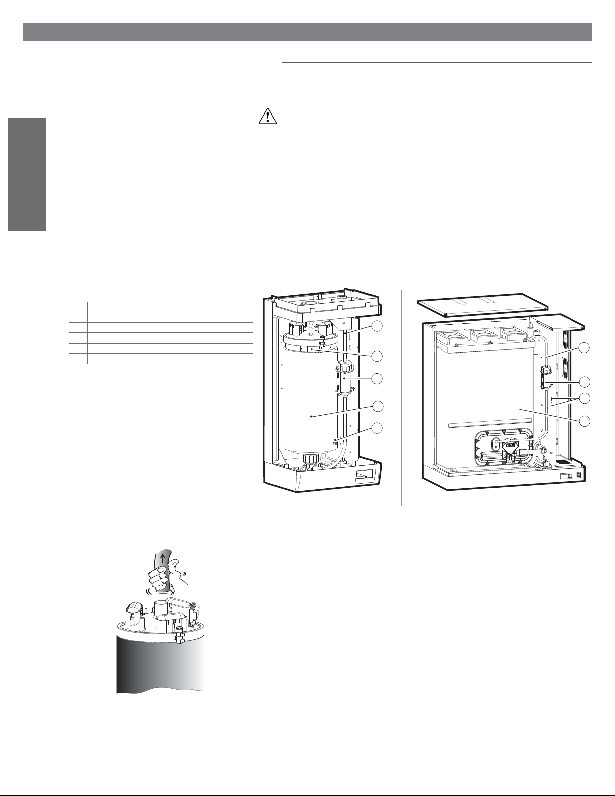
ENGLISH
Key:
n. description
1 pressure balancing pipe
2 cylinder fastener closing
3 level control
4 thermal lining (optional) with Velcro fastener
5 ground connection
14. MAINTENANCE
14.1 Maintenance of the cylinder-cylinder
For correct operation, the steam production cylinder must be periodically cleaned, at intervals linked to
the quantity of salts or impurities dissolved in the supply water. This operation is necessary as the lime
deposits that form inhibit the exchange of heat between the elements and the water.
IMPORTANT WARNING: do not use detergents or solvents to clean the components in the cylinder and
all other plumbing.
The unit must be cleaned in any case when the element over-temperature alarm is activated (see ALARMS AND TROUBLESHOOTING), signalled by:
• the lighting up of LED 1 and 3, for the type C control module (see Fig. 15.a);
• the display of the message CL for the type H or T control module.
The cylinder may be hot! Let it cool before handling, or use protective gloves.
To access the cylinder:
• turn the appliance off (Fig. 13.1) and open the disconnecting switch on the power line (safety procedure);
• completely empty the water contained in the cylinder (see SHUTTING DOWN THE UNIT);
• open and remove the casing (see Removing and replacing the front casing).
The layout of the humidifi er is as in Fig. 14.a.
1
1
2
Fig. 14.c
4
3
5
Fig. 14.a Fig. 14.b
To remove and clean the cylinder, follow the procedure as described below:
1. remove the steam pipe from the upper pipe union of the cylinder (Fig. 14.c);
2. electronically disconnect the level sensor (Fig. 14.a, part. no. 3);
3. remove, from the cylinder cover , the pressure equalising pipe with the level control tank (Fig. 14.a,
part. no. 1);
4. remove the protective covers of the element electrical connections (Fig. 17.a, part. no. 5) and
disconnect the power cables;
5. remove the cylinder ground screw (Fig. 14.a, part. no. 5);
6. undo the cylinder fastener by the lifting the black plastic lever (Fig. 14.a, part. no. 2) and pushing it
to the end of its stroke, thus releasing the stop system;
7. lift the cylinder to remove the upper pipe union from the drain unit and remove it from the machi-
ne, paying attention to any drops of water or deposits which may be released from the pipe union;
8. if present, remove the external thermal lining (Fig. 14.a, part. no. 4);
9. place the cylinder on a working surface which is protected by a material resistant to the water and
lime-scale which could be released during the cleaning operations;
10. release the cover ring fastening lever and push it to the end of its stroke (Fig. 17.a, part. no. 11);
remove the metal ring, the plastic cover and its connected parts from the cylinder (see Fig. 17.a that
shows the cylinder exploded view);
4
2
5
56
heaterSteam +030222011 - rel. 2.1 - 21.05.2010
Page 57

Cleaning of the cylinder fi lter 20-27-40-60 kg/h (44-59.5-88-132.2 lbr/h):
1. disconnect the pump power supply cable and the connection to the drain pipe;
2. remove from the fl ange the level sensor pipe;
3. unscrew the fastening screws of the fl ange;
4. remove the fl ange from the cylinder and clean thefi lter;
To remove and clean the cylinder of the humidifi ers from 20-27-40-60 Kg/h (44-59.5-88-132.2 lbr/h),
follow the procedure as described below:
1. remove the cover of the machine (hydraulic side) unscrewing the screws (Fig. 14.b);
2. remove the steam pipe from the upper pipe union of the cylinder (Fig. 14.c);
3. electronically disconnect the level sensor (Fig. 14.a, part. no. 3);
4. remove, from the cylinder cover, the pressure equalising pipe of the level control (Fig. 14.b, part.
no. 1);
5. remove the protective covers of the heating element electrical connections (Fig. 17.c part. no. 1) and
disconnect the power cables;
6. remove the cylinder ground screw (Fig. 14.b, part. no. 5);
7. if present, remove the external thermal lining (Fig. 14.b, part. no. 4);
8. remove the use fl ange (see fi lter cleaning);
9. remove the cylinder making it run on the din rails;
10. place the cylinder on a working surface which is protected by a material resistant to the water and
lime-scale which will be released during the cleaning operations;
11. remove the plastic cover and its connected parts from the cylinder
Before handling the elements, ensure that they are not hot! Use protective gloves if necessary.
12. Remove the non-stick fi lm (optional), if present, from the internal wall of the cylinder, and eliminate
any lime deposits from this using a jet of water (see Replacing the components
13. for humidifi ers up to 10 kg/h /22 lbr/h unscrew the ring nut on the lower cylinder pipe union and
remove the bottom fi lter, which can be reused after cleaning any deposits; the gasket can be reused
or, if damaged, can be replaced and ordered as a spare part (Fig.17.a, part. no.13-14 o Fig.17.b, part
12- 13);
14. the elements can also be cleaned without removing them from the upper cover; to do this, after
having removed the fl aky portion of lime, immerse the heating elements in a warm 20% solution
of acetic acid for 30 minutes, removing the remaining surface deposits with a non-metallic spatula,
then rinse well; if the plates are Tefl on-coated, avoid using any type of metal tools so as to not
damage the non-stick layer;
15. if necessary, the elements can be removed by unscrewing the fastening nut which holds them to
the plastic cover; in this case the seal gasket should be replaced;
16. remove the deposits and rinse the internal walls of the cylinder and the probe wells.
Fig. 14.d
ENGLISH
Re-assemble the cylinder by repeating the above operations in the reverse order, remembering to
re-fasten the ground screw (Fig. 14.a e .b, part. no. 5). The procedure described above refers to the
three-phase version (see Fig. 17.b).
For the power connections follow: Electrical diagram of the heating element connection corresponding
to the heads.
heaterSteam +030222011 - rel. 2.1 - 21.05.2010
57
Page 58
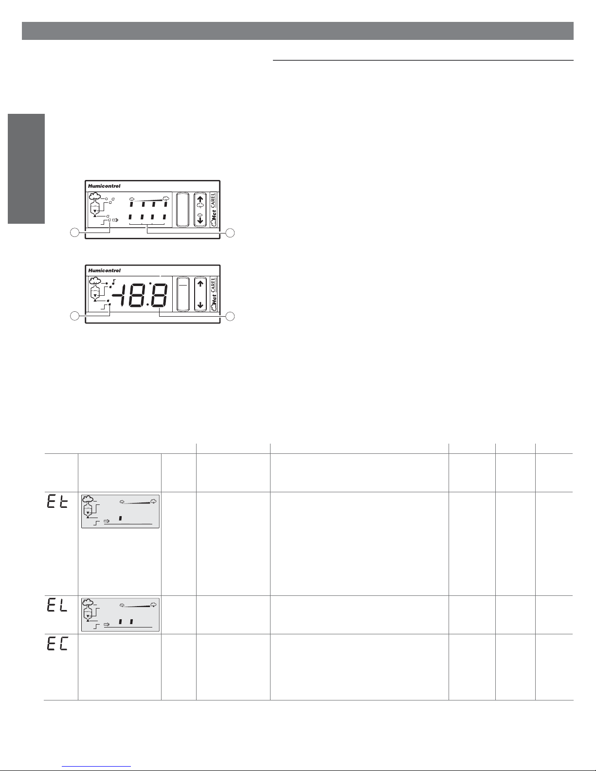
ENGLISH
15. ALARMS AND TROUBLESHOOTING
15.1 Alarm summary table
When an alarm is activated a message identifying the alarm is displayed on the control module.
In the case of potentially dangerous alarms, the control module automatically shuts the humidifi er down.
For some alarm events (see Table 15.a), the signalling of the alarm is accompanied by the activation of
an alarm relay, as described in: Other auxiliary contacts.
If the cause of the alarm is no longer valid, the humidifi er and alarm relay output can be reset automatically or manually, according to the type of problem, while the message displayed is deactivated manually
by pressing the reset-PRG button.
If no longer active, the alarm status continues to be indicated until the reset-PRG button is pressed.
Still active alarms can not be reset.
In the type C control module the presence of an alarm is indicated by the lighting up of LED 9 and
a combination of the LEDs 5 (Fig. 15.a); in the event of more than one alarm, these are indicated in
sequence, at 2 second intervals.
30% 50% 75% 100%
alarm
9
1234
reset
5
Fig. 15.a
dehum. x1000
alarm
9
PRG
reset
SEL
5
Fig. 15.b
In the type H or T control module, if not in programming phase, in the presence of an alarm LED 9 (see
fi g. 15.b) begins fl ashing, while the display 5 indicates the alphanumeric alarm code.
The message is displayed cyclically, for a duration of two seconds, alternating with the measurement
normally displayed (if the measurement normally displayed corresponds to a disconnected probe, the
measurement is not displayed; this will automatically return to the display if the probe is reconnected).
In the event of more than one alarm, the display indicates all the corresponding codes in sequence, at
two second intervals.
The alarm Ec cannot be reset.
In the event of the alarm CL (regular maintenance required), the alarm can be reset only by resetting the
hour counter; see Resetting the hour counter.
The alarm E1 may appear in two distinct cases:
1. Malfunction when reading from the parameter memory (typically on start-up)
The default parameters are temporarily recalled, without being saved in the parameter memory (the
parameters can be accessed and the correct values restored).
In any case the default parameter recall procedure is recommended; see Recalling the default
parameters.
2. Malfunction when writing to the parameter memory (typically on pressing the PRG button)
Any modifi cations made will be cancelled; the parameters can be accessed, the values modifi ed and
save operation repeated.
H and T
controller
code displayed
C controller CAREL
cause solution
Humivisor
remote
terminal
E202 •activation of safety
thermostat
• Klixon activation
•the thp output is open
alarm
30% 50% 75% 100%
1234
E204 contradiction of the fl oat - check the correct supply of water to the cylinder;
30% 50% 75% 100%
alarm
1234
non previsto E205 high conductivity of the
supply water
Table 15.a lists the alarm indications, the causes, the conditions and the possible solutions.
The remote terminal column indicates the alarm message that appears on the LCD display of the CAREL
Humivisor remote control panel, if one is connected to the humidifi er.
( once having tried the suggestion, if the problem
persists, contact the CAREL service department)
- check the earth current of the heaters, and if replace necessary.
- manually reset the Klixon
- problem dependent mainly on operation without water;
- turn the machine off and, once it has cooled down, reactivate
the thermostat on the cylinder cover after having cleaned the
action reset alarm
relay
not available active
if Et remain
in order at
least
a
minute.
cylinder and the level control, checking the effi ciency of the
components;
- check that the electrical and water connections are in order
and that the machine is supplied correctly;
- it may be necessary to replace the PTC sensors if installed
- turn the machine off and clean: the cylinder, the level control
and the fi ll electrovalve
- turn the machine off and clean the water conductivity measuring electrodes;
see procedure
“AR”
total shutdown auto
manual only if EE
appears
during AR
active
available
- if the problem persists, change the source of the supply water
or install a suitable treatment system (demineralisation, even
partial);
- the problem will not be resolved by softening the supply
water
58
heaterSteam +030222011 - rel. 2.1 - 21.05.2010
Page 59
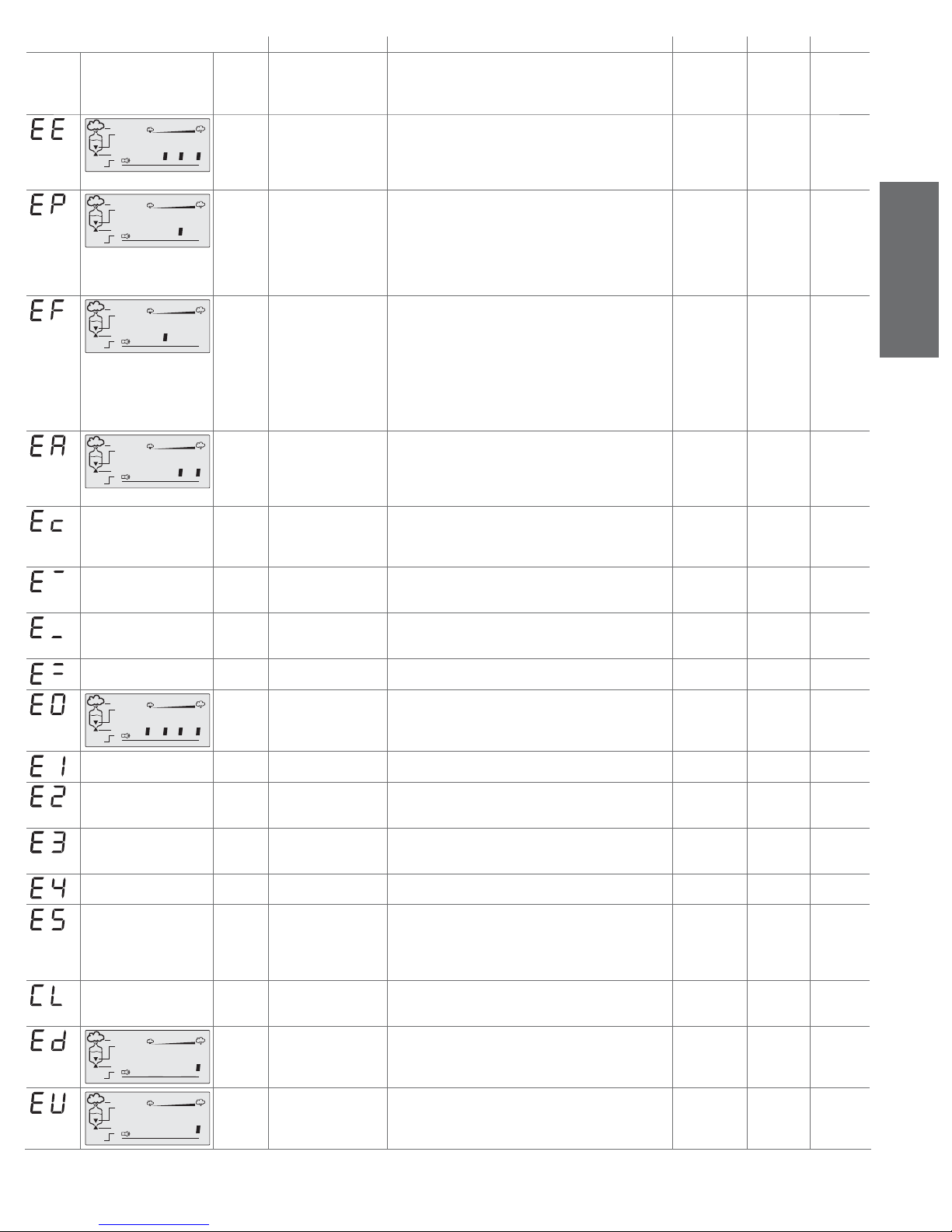
H and T
controller
code displayed
C controller CAREL
Humivisor
cause solution
persists, contact the CAREL service department)
( once having tried the suggestion, if the problem
action reset alarm
remote
terminal
alarm
alarm
30% 50% 75% 100%
1 2 3 4
30% 50% 75% 100%
1234
E211 autotest failed;
probable problems
in: supply water, level
control or electrovalve
E213 • electrical power not
available; on machine
start-up no steam is
produced or the
- ensure that the machine is supplied with water;
- turn the machine off and clean the level control and the fi ll
valve
with the machine off and disconnected from mains power supply, check that there are no defective of malfunctioning electrical
connections
see procedure
“AR”
see procedure
“AR”
manual active
manual active
water is not pre-heated
•fl oat locked in high level
position.
alarm
alarm
30% 50% 75% 100%
1234
30% 50% 75% 100%
1234
E214 no water - check that the supply pipe from the water supply to the
humidifi er and the internal pipe is not blocked or choked and
that the pressure is suffi cient (1-8 bar);
- check the operation of the fi ll electrovalve;
- check that the steam supply does not have to work against
excessive back-pressure, preventing the fl ow of water into the
cylinder due to gravity;
- check that the steam supply pipe is not choked or that there
are no pockets of condensation
E215 formation of foam in the
cylinder during boiling
- the formation of foam is usually due to the presence of
surfactants in the water (lubricants, solvents, detergents, water
treatment or softening agents) or an excessive concentration
of dissolved salts. Drain the water supply line;
humidifi er
disabled
manual or
automatic (if
after waiting
after waiting 10
min the alarm
is automatically
10 min the
water supply
returns)
reset and a
new fi ll cycle is
attempted
signal only manual not active
- clean the cylinder
not featured E231 high water conductivity
pre-alarm
- check the conductivity of the supply water;
- if necessary, install a suitable water treatment system;
humidifi er
disabled
auto
available
- the problem will not be resolved by softening the supply
water
not featured E221 high ambient humidity
(high temperature in T
check the operation of the probe and the limit set by parameter P2signal only auto
available
control)
not featured E222 low ambient humidity
low temperature in T
check the operation of the probe and the limit set by parameter P3signal only auto
available
control)
not featured E224 high outlet humidity check the operation of the outlet probe signal only auto
available
E201 internal memory error contact the CAREL service department humidifi er
30% 50% 75% 100%
alarm
1234
not featured E212 user parameter error with the machine off check that there are no defective or
malfunctioning electrical connections
disabled
humidifi er
disabled
not featured E230 hour counter error reset the hour counter (see Resetting the hour counter) hour counter
saving disabled
reprogram
CAREL
reprogram
parameters
manual hour
counter
reset
not featured E220 room probe not con-
nected
check the connection of the probe and the setting of parameter
A0 for ON/OFF confi guration (see Reading and programming
humidifi er
disabled
auto
available
the parameters)
not featured E223 outlet probe not con-
nected (if featured)
not featured E225 NTC probe for measuring
the water temperature
not connected (if
featured)
check the connection of the probe or the setting of parameter
A0 (see Reading and programming the parameters)
- check the pre-heating operation and the setting of
parameters b1, b2, b3 (see Reading and programming the
parameters);
- check the connections to the terminal block on the cylinder
humidifi er
disabled
pre heating
disabled
auto
available
auto
available
cover
not featured E232 regular maintenance
signal
stop the machine and carry out a complete maintenance routine
on the humidifi er, resetting the hour counter (see Resetting the
signal only manual not active
hour counter)
alarm
alarm
30% 50% 75% 100%
1234
30% 50% 75% 100%
1234
E216 no drain pre-alarm or
fi lter blocked
E233 boiler full of water
with no humidifi cation
demand pre-alarm
- check the drain valve/pump;
- check if the pipes or the manifold are blocked;
- check if the level sensor is faulty or the pipes are blocked;
- the fi lter inside the boiler may be clogged.
- check if the fi ll valve is leaking;
- check if the high level sensor is dirty.
see procedure
manual active on
“AR”
signal only auto
available
relay
only on the
second EP
or after EE
during AR
only on the
second EP
or after EE
during AR
active
ENGLISH
not active
active
active
active
active
active
not active
active
active
active
the second
“Ed”
not active
Table 15.a
heaterSteam +030222011 - rel. 2.1 - 21.05.2010
59
Page 60
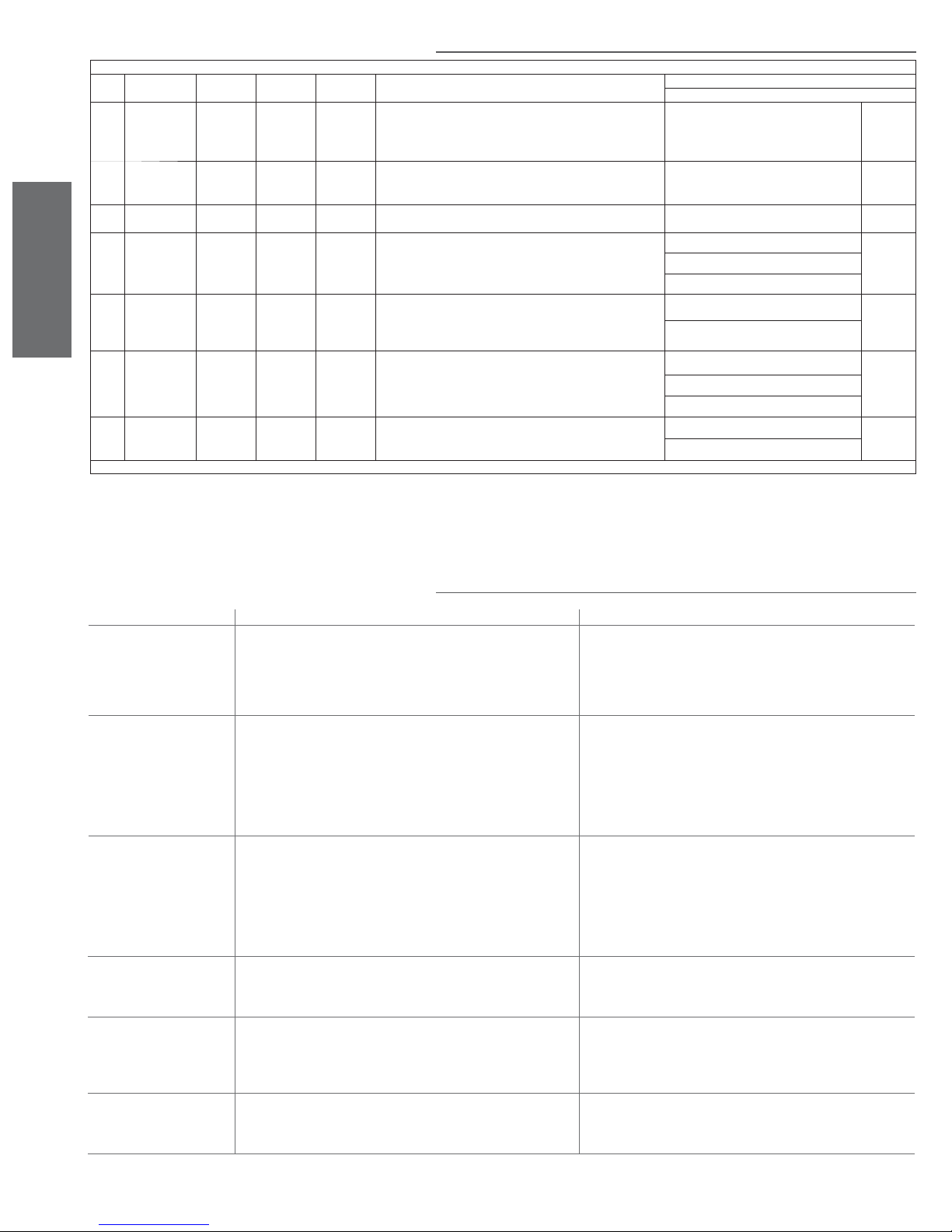
Step Description Drain
status
1 Stop produc-
tion.
Open contactor
Off Off Off 3 sec No
Fill status Contactor
status
15.2 Autotest Retry procedure (Fault tolerance)
AUTOTEST RETRY (“AR”)
Duration Condition that can stop “AR”
Display
2 Drain by time On Off Off If at the end of a set time the fl oat is below to the minimum reed,
3 Wait for level
to stabilise
4 Fill water Off On Off Ends when the fl oat reaches the control reed Contradiction of the levels EE
5 Wait for level
ENGLISH
to stabilise
6 Drain On Off Off Ends when the fl oat reaches the control reed Contradiction of the levels EE
7 Wait for level
to stabilise
Off Off Off 3 sec High level sensor active EE
Off Off Off 10 sec Contradiction of the levels EE
Off Off Off 1 sec Contradiction of the levels EE
the procedure goes to step 3, otherwise it drains again and then
goes to step 3
High level sensor active EE
High level sensor active
The fi ll time exceeds a maximum limit
High level sensor
High level sensor active
The drain time exceeds a maximum limit
High level sensor active
NOTE:
- During the Autotest Retry procedure the display shows the code “AR” alternating with the alarm code
that triggered the procedure.
- If the PRG button is pressed during the Autotest Retry procedure, the procedure is stopped and normal
humidifi er operation resumes.
15.3 Troubleshooting
Problem Cause Solution
The control does not turn on 1. no electrical power supply;
2. external switch in position 0 (open);
3. control connectors poorly installed;
4. fuses blown;
5. transformer malfunction.
The humidifi er does not
start
The humidifi er fi lls with water
without producing steam
Line circuit breaker is activated 1. the line circuit breaker is rated too low;
The humidifi er wets the
duct
The humidifi er wets the fl oor
below
1. remote ON/OFF contact open (relay/terminals 7I - 8I);
2. the external regulator/humidistat or probe has not been connected
correctly;
3. probe/humidistat malfunction;
4. parameters not set correctly;
5. safety thermostat activated;
6. fan circuit breaker activated (H or T control);
1. steam outlet back-pressure too high;
2. leaking fl ow regulator in the water fi ll electrovalve (with leaks in the water
circuit);
3. level control malfunction;
4. cylinder inlet fi lter blocked;
5. lime in the fi ll tank;
6. drain electrovalve malfunction;
2. resistors short-circuited
1. the distributor is not installed correctly;
2. the system is rated too high;
3. the humidifi er is active when the duct fan is off;
1. the humidifi er pipe is blocked;
2. the water supply or overfi ll circuit has leaks;
3. the condensate drain pipe does not drain the water back to the fi ll tank;
4. the steam outlet pipe is not properly attached to the cylinder;
60
1. check the protection devices upstream of the humidifi er and the mains
power supply;
2. close the switch: position I;
3. check that the connector are properly installed on the terminal block;
4. check the state of fuses F1/F2;
5. check that the secondary of the transformer has an output of 24 Vac.
1. close ON/OFF contacts (relay/terminals 7I - 8I);
2. check the external connection;
3. check the external signal;
4. reprogram the parameters correctly;
5. reset the thermostat after having eliminated the cause of the problem;
6. reset the circuit breaker after having eliminated the cause of the
problem;
1. check that the steam outlet pipe is not bent or choked;
2. replace the fi ll electrovalve;
3. clean the level control or replace if necessary;
4. clean the fi lter;
5. clean the fi ll tank;
6. check for the presence of 24Vac at the drain electrovalve; clean the drain
electrovalve;
1. check that the circuit breaker is rated for a current of at least 1.5 times
the rated current of the humidifi er;
2. check, by measuring, the value of the resistors and replace them if
necessary
1. check that the steam distributor has been installed correctly;
2. diminish the steam production set on the control;
3. check the connection of the device (fl ow switch or differential pressure
switch) linked to the humidifi er for ventilation in the duct (terminals
7I - 8I)
1. clean the pipe in the bottom tank;
2. check the entire water circuit;
check the correct positioning of the condensate drain pipe in the fi ll tank;
3. check the fastening of the pipe clamp on the steam outlet pipe;
heaterSteam +030222011 - rel. 2.1 - 21.05.2010
Tab. 15.b
Table 15.c
Page 61
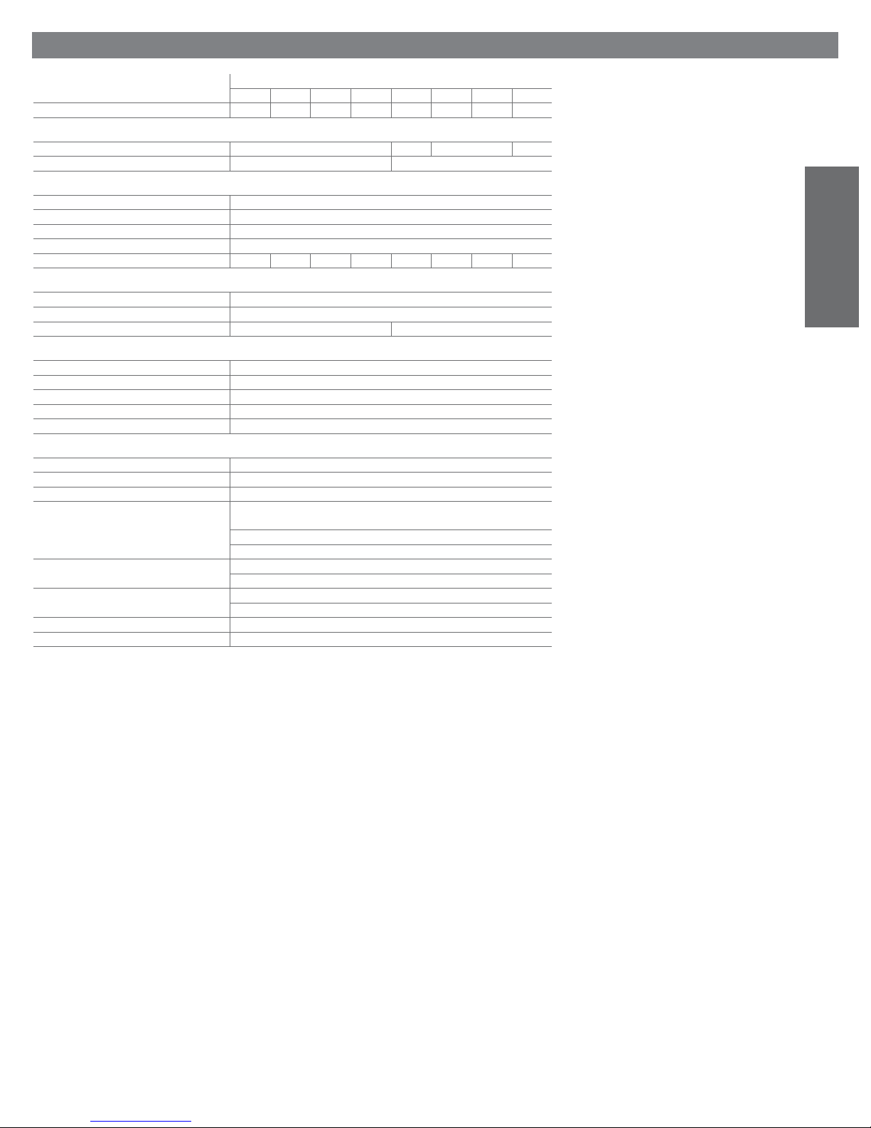
16. HUMIDIFIER TECHNICAL SPECIFICATIONS
model
UR002 UR004 UR006 UR010 UR020 UR027 UR040 UR060
number of heating elements 1 1 3 3 6 6 6 9
steam
connection ( mm)( inch) 30/1.18
supply pressure limits (Pa) 0…1500 2000
supply water
connection G3/4”M
temperature limits (°C)(°fH) 1T40/33.8T104
pressure limits (MPa) 0.1 to 0.8 (1 to 8 bar)
hardness limits (°fH) 40
instant fl ow rate (l/min) (gpm)
drain water
connection ( mm)( inch) 40/1.57
typical temperature (°C)(°fH) 100 / 212
instant fl ow rate (l/min)(gpm) 5/1.32 22,5/5.94
environmental conditions
ambient operating temperature (°C) 1T40/33.8T104
ambient operating humidity (% rH) 10 to 60
storage temperature (°C) (°fH) -10T70/14T158
storage humidity (% rH) 5 to 95
index of protection IP20
control
type URC-URH-URS
voltage / auxiliary frequency (V / Hz) 24 / 50/60
maximum auxiliary power (VA) 30
probe inputs (general characteristics) selectable input signal: 0 to 1 Vdc, 0 to 10 Vdc, 2 to 10 Vdc, 0 to 20 mA,
power to active probes (general characteristics) 24 Vdc (24 Vac rectifi ed), Imax= 250 mA
alarm relay and dehumidifi cation outputs
(general characteristics)
remote enabling input (general characteristics) free contact; max. resistance max. 50 ; Vmax=24 Vdc; Imax=5 mA
serial communication two-lead RS485
0,6/0.13 0,6/0.13 1,2/0.26 1,2/0.26
input impedance: 60 k with signals: 0 to 1 Vdc, 0 to 10 Vdc, 2 to 10 Vdc
50 with signals: 0 to 20 mA, 4 to 20 mA
12 Vdc 5%, Imax= 50 mA
type of micro-switching action 1C
40 /1.57
4/0.88 4/0.88 4/0.88
4 to 20 mA
250 V 8 A (2 A)
40/1.57 2 x4 0/1.5 7
10/2.2
Table 16.a
ENGLISH
heaterSteam +030222011 - rel. 2.1 - 21.05.2010
61
Page 62
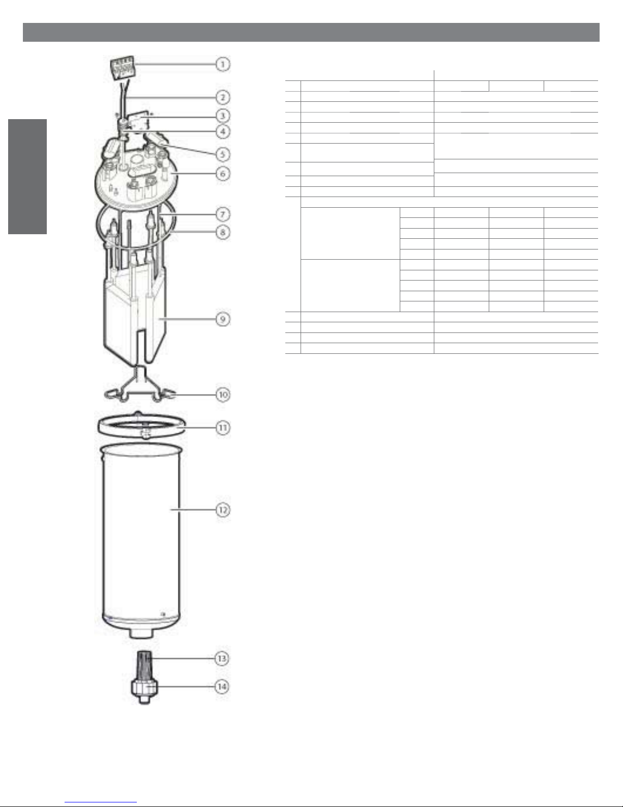
ENGLISH
17. SPARE PARTS
Exploded of the cylinder 6-10kg/h ( 13.2-22 lbs/h )
n. description UR006 – 1 ~ * UR006 – 3~** UR010 – 3~**
1 PTC probe wire terminals URKTB00000
2 NTC Probe URKNTC0000
3 Wire terminal bracket URK0000022
4 NTC well URKNTCCAS1
5 Power connection protection cover URKCOPC00M
6 Cylinder cover
8 Cylinder gasket
11 Cylinder cover locking clamp
7 PTC probe URKPTCS000
9 Heating elements:
with antiadherent fi lm 208V
without antiadherent fi lm 208V
10 Heating element centring spring 13C453A048 ---12 Cylinder URKB100000
13 Filter, ring nut and pipe union UEKF000000
- Gasket kit URKG00000M
230V
400V
460V
575V
230V
400V
460V
575V
Spare Parts Code
URKG100000
URKBR00000
URKH00A347 URKH00A347 URKH00A346
URKH00A320 URKH00A320 URKH00A322
URKH00A320 URKH00A322
URKH00A344 URKH00A347
URKH00A341 URKH00A342
URKH00R347 URKH00R347 URKH00R346
URKH00R320 URKH00R320 URKH00R322
URKH00R320 URKH00R322
URKH00R344 URKH00R347
URKH00P341 URKH00R342
Tab. 17.a
Fig. 17.a
62
heaterSteam +030222011 - rel. 2.1 - 21.05.2010
Page 63
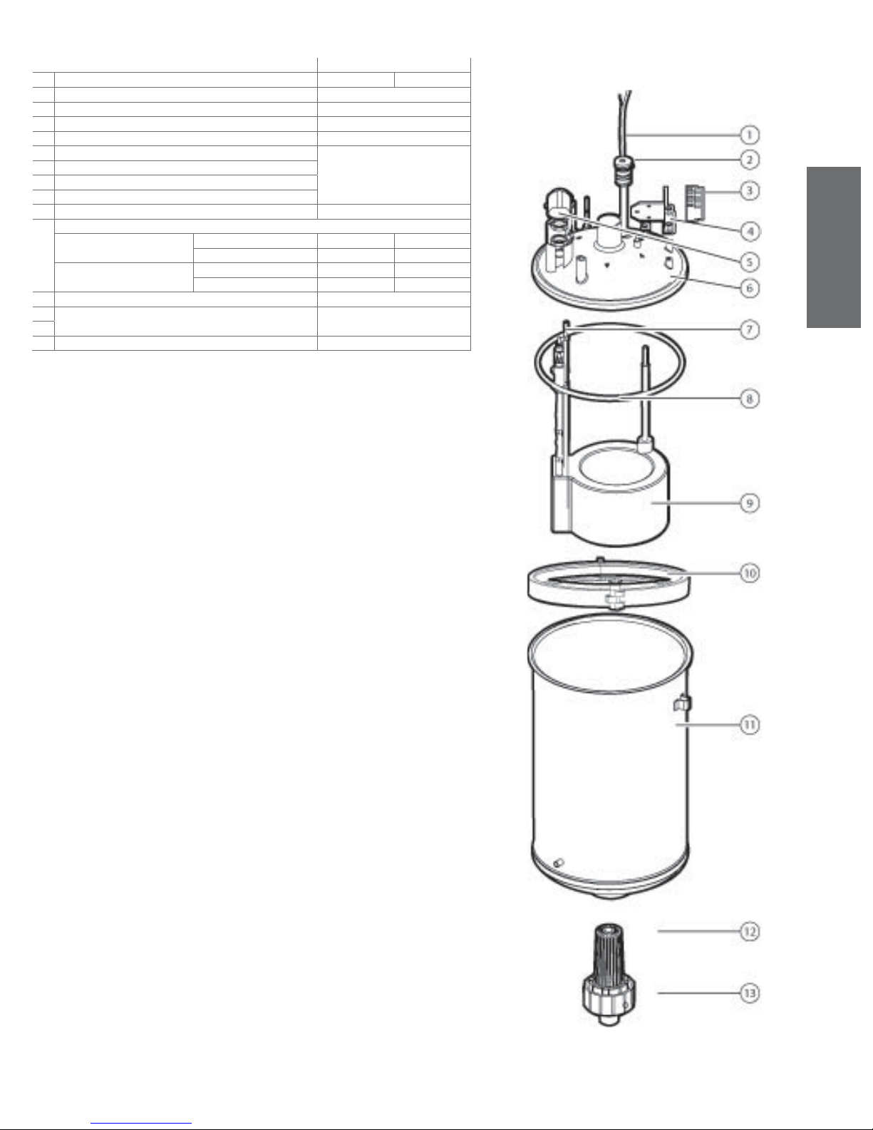
Exploded of the cylinder 2-4 kg/h ( 4.4 - 8.8 lbs/h)
Spare Parts Code
n. description UR002 UR004
1 NTC probe URKNTC0000
2 NTC well URKNTCCAS2
3 PTC probe wire terminals URKTB00000
4 Terminal fastening bracket URK0000022
5 Power connection protection cover URKCOPC00S
6 Cylinder cover
8 Cylinder gasket
10 Cylinder cover locking clamp
7 PTC probe URKPTCS000
9 Heating elements:
with antiadherent fi lm 208V
230V
without antiadherent fi lm 208V
230V
11 cylinder URKB040000
12 fi lter, ring nut and pipe union UEKF000000
13
- Gasket kit URKG00000M
URKH00A348 URKH00A349
URKH00A348 URKH00A349
URKH00R348 URKH00P349
URKH00R348 URKH00P349
URKG100000
URKBR00000
ENGLISH
Tab.le17.b
heaterSteam +030222011 - rel. 2.1 - 21.05.2010
Fig. 17.b
63
Page 64
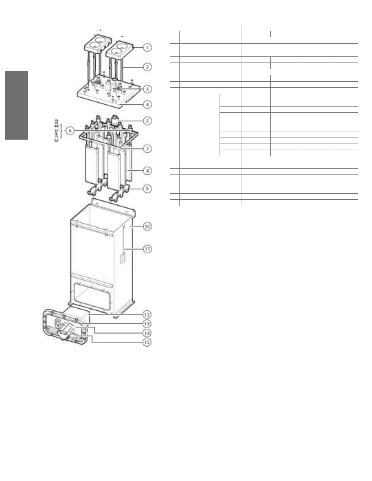
Exploded of the cylinder 20-27-40-60 kg/h 44.1-59.5-88.1-132.3 lbs/h )
Spare Parts Code
n. description UR020 UR027 UR040 UR060
1 Heating element protection ---2 PTC probe URKPTCL000
ENGLISH
3 PTC probe wire terminals URKTB00000 URKTB00000 URKTB00000 URKTB00000
4 Cylinder cover
URKCOP4000 URKCOP4000 URKCOP4000 URKCOP6000
5 Anti-foaming system URKFS00000
6 Heating element assembly --- -- -- -7 Cylinder gasket
URKG400000 URKG400000 URKG400000 URKG600000
8 Heating element 6 x 6 x 6 x 9 x
with antiadherent fi lm 208V
230V
400V
460V
575V
without antiadherent
fi l m
208V
230V
400V
460V
575V
URKH00A382 URKH00A383
URKH00A381 URKH00A382
URKH00A381 URKH00A382 URKH00A387 URKH00A387
URKH00A386 URKH00A381 URKH00A390 URKH00A390
URKH00A385 URKH00A380 URKH00A389 URKH00A389
URKH00R382 URKH00R383
URKH00R381 URKH00R382
URKH00R381 URKH00R382 URKH00R387 URKH00R387
URKH00R386 URKH00R381 URKH00R390 URKH00R390
URKH00R385 URKH00R380 URKH00R389 URKH00R389
9 Heating element centring spring ---10 Cylinder
11 NTC probe
URKB270000 URKB400000 URKB600000
URKNTC0000
12 Use fi lter URKF0000XL
13 Use fl ange URKFLAN000
14 Pump fastening braket URKFLAN000
15 Drain pump KITPSR0000
- Gasket kit URKG0000XL URKG000XXL
Table17.c
Fig. 17.c
64
heaterSteam +030222011 - rel. 2.1 - 21.05.2010
Page 65
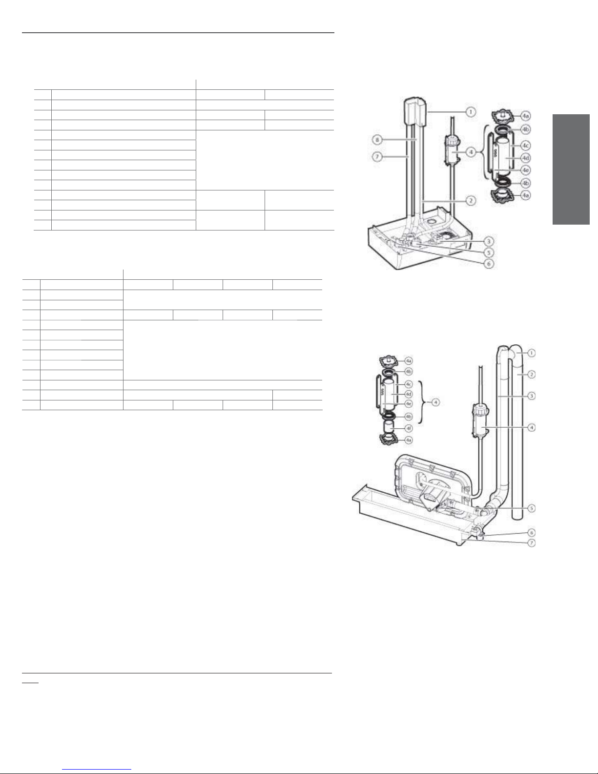
17.a Maintenance of the other plumbing components
IMPORTANT WARNINGS: do not use detergents or solvents to clean the plastic components. To remove
the deposits use a 20% acetic acid solution, then rinse thoroughly with water.
Water parts ur 2-10kg/h ( 4.4 - 22 lbs/h)
Spare part codes
n. description UR002 to UR004 UR006 to UR010
1 tank UEKVASC000
2 Supply pipe URKT00000S URKT00000M
3 Fill electrovalve KIT VC00006 KITVC0012
4 Level control: URKSL00004
4a sensor cap
4b o-ring
4c sensor fl oating
4d sensor pipe
4e control board
5 Drain electrovalve URKDRAIN00 URKDRAIN00
6 A/D manifold (fi ll - drain)
7 Drain pipe URKT00000S URKT00000M
8 Overfl ow pipe
Water parts ur 20-27-40-60 kg/h ( 44.1-59.5-88.1-132.3 lbs/h )
Spare part codes
n. description UR020 UR027 UR040 UR060
1 Overfl ow pipe URKDC00000
2 Drain column
3 Supply pipe URKT0000XL URKT0000XL URKT000XXL URKT000XXL
4 Level control: URKSL00004
4a Sensor cap
4b o-ring
4c sensor fl oating
4d sensor pipe
4e control board
5 Drain pump KITPSR0000
6 Fill electrovalve KITVC00040 KITVC00100
7 Drain tank -- -- -- --
ENGLISH
Table 17.d
Fig. 17.d
Table 17.e
• Fill electrovalve (Fig. 17.d, part. no. 3 - Fig. 17.e, part. no. 6)
After having disconnected the cables and the pipe, remove the electrovalve and check the state of the inlet
fi lter, cleaning it if necessary using water and a soft brush.
• Supply and drain manifold (Fig. 17.d, part. no. 6)
Check that there are no solid residues at the cylinder coupling; remove any impurities.
Check that the O-ring is not damaged or cracked; replace it if necessary.
• Drain electrovalve / drain pump (Fig. 17.d, part. no. 5 – Fig. 17.e, part. no.5)
Disconnect the power cables, remove the bobbin and remove the valve block after having unscrewed the
two fastening screws from the manifold; remove any impurities and rinse; as regards the pump it is suffi cient to screw the clamping screw and remove possible impurities;
• Fill tank (Fig. 17.d, part. no. 1)
Check that there are no blockages or solid particles and that the conductivity measuring electrodes are clean,
remove any impurities and rinse.
• Supply, fi ll, overfi ll pipe (Fig. 17.a, part. no.2-8 – Fig. 17.e, part. no. 3-1)
Check that they are free and do not contain any impurities; remove any impurities and rinse.
• Level control (Fig. 17.d, part. no.4 – Fig. 17.e, part. no. 4)
The level control must be released from the partition wall of the cabinet. Disconnect the connector from the
terminals of the electronic board, take off the connection pipes. Release the spacers and the board, then
take off the caps. Check that the o-rings are not damaged or cracked; replace them if necessary. Check the
cleanliness and free sliding of the two fl oat switches.
Clean all the components and reassemble and replace the device.
Carefully check that the connection pipes are properly fi tted and that they are not blocked or choked at any
point.
IMPORTANT WARNING: after having replaced or checked the plumbing components, check that the
connections have been carried out correctly, with their corresponding seals. Re-start the machine and run
through a number of fi ll and drain cycles (from 2 to 4), at the end of which, applying the safety procedure,
check for any water leaks.
Fig. 17.e
heaterSteam +030222011 - rel. 2.1 - 21.05.2010
65
Page 66

ENGLISH
17.2 Replacing the components
17.2.1 Non-stick fi lm
If requested as an option, the internal wall of the cylinder is lined with a non-stick fi lm to avoid lime
being deposited on the internal walls of the cylinder. To clean or replace the fi lm, remove the cylinder
following the procedure described in Maintenance of the cylinder-cylinder and then:
• slowly remove the fi lm towards the mouth of the cylinder, without forcing it to avoid damage;
• open the fi lm after having released the click-on couplings;
• clean the fi lm with water and a plastic spatula if necessary; replace the fi lm if damaged;
• wind the fi lm around itself, reinserting the click-on couplings, and place it into the cylinder after the
latter has been carefully cleaned and freed from deposits.
17.2.2 Elements
To replace the elements remove the cylinder following the procedure described in Maintenance of the
cylinder-cylinder and loosen the fastening nuts from the threaded spigots of the elements.
Before reassembling the elements, check the state of the gaskets and replace them if necessary.
17.2.3 PTC overtemperature sensor
The PTC sensors (one for each heating element) do not require regular maintenance; they should only
be replaced if the safety thermostat is activated due to operation without water: in fact, the intervention
of just one PTC will cause the control module to shut-down operation.
To replace the sensors, remove the cylinder following the procedure described in Maintenance of the
cylinder-cylinder and then:
• disconnect the PTC sensor terminals (see Fig.: 7.p.a to 7.p.n);
• remove the electrical elements corresponding to the sensors being replaced;
• unscrew the PTC sensor (fi g. 17.a, part. no. 7 or Fig. 17.b part. no. 7 or Fig. 17.c part. no. 2) using a
spanner on the hexagonal spigot, accessible from the under side of the cover;
• reassemble a new PTC sensor, replacing the o-ring and screwing it tight; reconnect the terminals;
• reposition the electric heating elements, making sure the PTC sensor enters into the corresponding
sheath in the aluminium casting.
17.2.4 NTC temperature sensor (version with type H or T control module only)
As for the PTC sensors, the NTC sensor controlling the water temperature does not require regular
maintenance.
To replace this sensor, remove the cylinder following the procedure described in Maintenance of the
cylinder-cylinder and then:
• disconnect the terminals of the NTC sensor (see Fig.: 7.p.a to 7.p.n);
• remove the sensor from the well housed in the measuring sheath (fi g. 17.a part. no. 2, or Fig. 17.b
part. no. 1, or Fig. 17.d part. no. 11);
• reposition and connect the new sensor in the place of the old one.
66
heaterSteam +030222011 - rel. 2.1 - 21.05.2010
Page 67
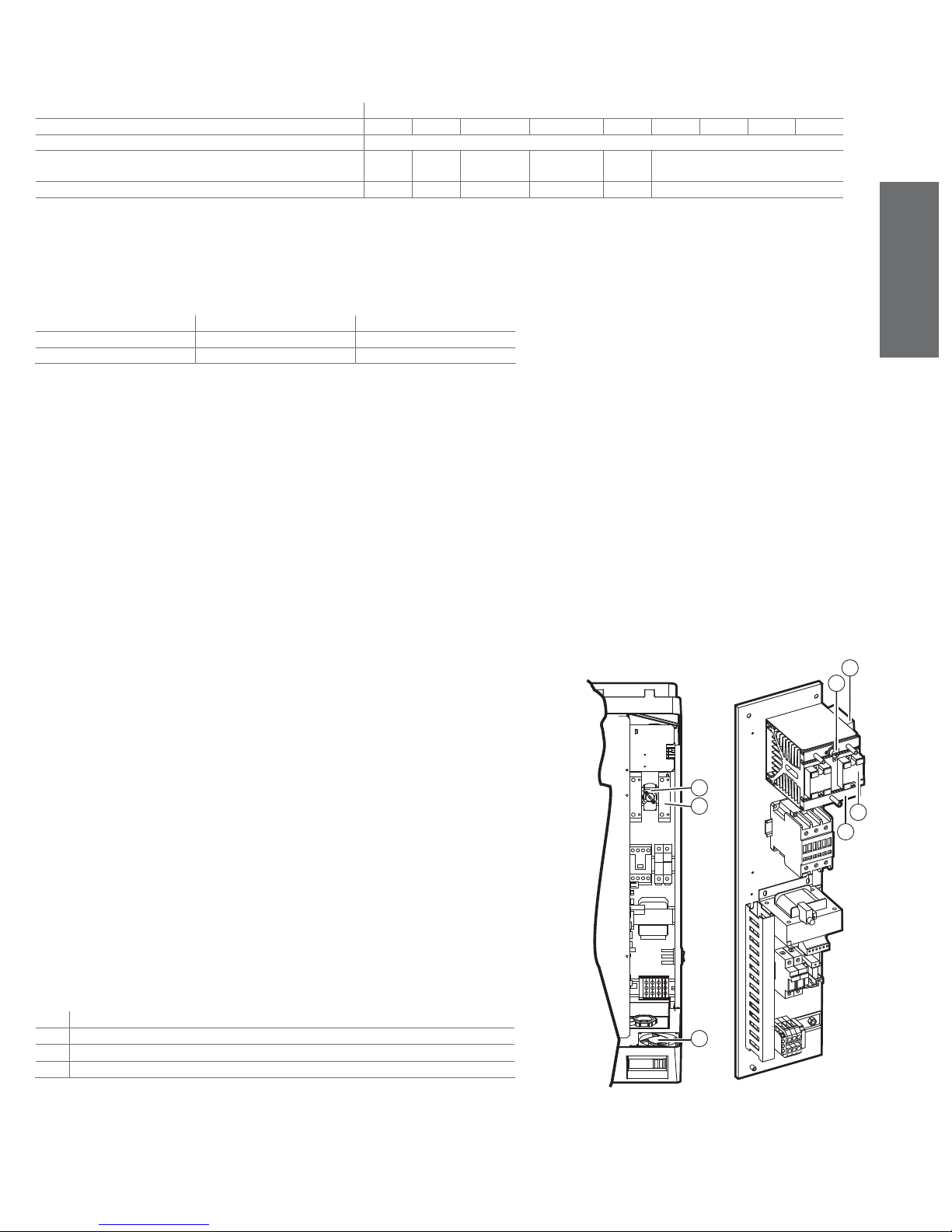
17.2.5 Fuses (uxiliary circuit)
These measure 10.3 x 38mm and are housed in the fuse cartridge; to check the state of the fuses, check
their continuity using a tester.
Use the types of fuses indicated in table 17.e.
models
UR002 UR004 UR006 - 1~* UR006 -3~** UR010 UR020 UR027 UR040 UR060
fuses 1 and 2 transformer power supply All fast blow and capacity 1 A, GL, 10,3x38 contained in fuse carrier on Omega rail
fuses 3 pump protection (on humidifi ers from 20 to 60kg/h) (44.1 to
132.3 lbs/h)
Fuse 4 transformer secondary 2,5 A,T 5x20 in pottery
*: single-phase **: three-phase
1 A GL , 10,3x38 FAST
17.2.6 Load protection fuses (humidifi ers UR027 at 208-230 V, UR060 at 460 V)
Dimension of the fuses 27x60 mm rapid, housed in fuse carrier bases that can be selected. Check their
continuity using a tester.
UR027 UR060
fuses F5, F6, F7 40 A, GG 35 A, GG
fuses F8, F9, F10 40 A, GG 50 A, GG
Table 17.g
17.2.7 Solid state relays (version with type H or T control module only)
The solid-state relays (one in the single-phase unit, two in the three-phase unit) can malfunction in one
of two ways: by short-circuit or burn-out. The respective consequences for the supply of power are:
continuous conduction or permanent opening.
In the event of malfunctioning, check the conduction of the relay using a tester.
For the replacement of the solid-state relay:
• turn the humidifi er off;
• open the disconnection switch in the power line (safety procedure);
• disconnect the power and auxiliary cables from the solid-state relay terminal block;
• remove the relay from the electrical panel by using a screwdriver to lower the fastening lever to the
omega guide;
• replace the new relay on the omega guide and reconnect the wires as before.
Table 17.f
ENGLISH
17.2.8 Cooling fan and circuit breaker (version with type H or T control module only)
The SSR relays are cooled by a fan placed in the upper part, on the right side of the machine for the
20-60kg/h (44-132.2lbr/h) models, or placed on the base of the humidifi er for the models up to 10kg/h
(22lbr/h).
With insuffi cient ventilation the temperature of the electrical panel may rise excessively until, reaching
65°C, power to the solid-state relays is cut by a special Klixon (heat sensor, used in this application as
circuit breaker - hereafter: circuit breaker), with manual reset (indicated by S2 in the wiring diagram) and
without an activation signal. In this case, check:
• Whether the thermoprotective placed in the din rail near to the SSR relays has been working, or
placed in front of the baffl e pressing the reset button (see Fig. 17.f);
• that the fan power board, fi tted in front of the baffl e, is powered (input terminals: 24 Vac) and in turn
powers the fan (output terminals: 24 Vdc), (only for models up to).
If the fan is faulty:
- in the models up to 10 Kg/h (22 lbs/h):
• remove the baffl e, after having unscrewed the two side nuts for fastening to the partition of the
appliance;
In case of malfunction, the thermoprotective can be replaced unscrewing the fastening screws;
- in the 20-27-40-60 Kg/h
( 44.1-59.5-88.1-132.3 lbs/h ) models:
• unscrew the 4 fastening screws placed on the right side of the structural work and extract the fan
from the inside of the panel.
In case of malfunction, the thermoprotective can be replaced removing the polycarbonate transparent
protection of the solid state relays and unscrewing the fastening screws.
Key:
1 Klixon (thermoprotective - where fi tted)
2 solid state relay (SSR) (where fi tted)
3 fan (where fi tted)
4 heatsink
3
1
1
2
3
2
4
heaterSteam +030222011 - rel. 2.1 - 21.05.2010
Fig. 17.f
67
Page 68

ENGLISH
17.3 Spare parts
Models UR002 UR004 UR006 - 1~* UR006 - 3~** UR010 UR020 UR027 UR040 UR060
plumbing
humidifi er gasket kit URKG00000M URKG00000M URKG00000M URKG00000M URKG00000M URKG0000XL URKG0000XL URKG0000XL URKG000XXL
Cylinder gasket kit
cylinder cover kit URKCOPC00S URKCOPC00S URKCOPC00M URKCOPC00M URKCOPC00M
boiler cover locking bracket URKBR00000 URKBR00000 URKBR00000 URKBR00000 URKBR00000
cylinder fi lter kit UEKF000000 UEKF000000 UEKF000000 UEKF000000 UEKF000000 URKF0000XL URKF0000XL URKF0000XL URKF0000XL
Tefl on-coated heating elements
non-Tefl on heating elements
cylinder fastening strap
steel cylinder URKB040000 URKB040000 URKB100000 URKB100000 URKB100000 URKB270000 URKB270000 URKB400000
fi ll tank
drain electrovalve kit
drain pump kit
drain pipe kit URKT0000XL URKT0000XL URKT000XXL URKT000XXL
fi ll valve KITVC00006 KITVC00006 KITVC00012 KITVC00012 KITVC00012 KITVC00040 KITVC00040 KITVC00040 KITVC00100
internal pipe kit URKT00000S URKT00000S URKT00000M URKT00000M URKT00000M URKT0000XL URKT0000XL URKT000XXL URKT000XXL
level control with sensor URKSL00004 URKSL00004 URKSL00004 URKSL00004 URKSL00004 URKSL00004 URKSL00004 URKSL00004 URKSL00004
non-stick fi lm
external terminal covering
electrical parts
contactor
voltage 208 V
power supply transformer
voltage 230 - 400 V URKTR10000 URKTR10000 URKTR10000 URKTR10000 URKTR10000 URKTR40000 URKTR40000 URKTR40000
fuse carrier
voltage 460 V
fuses
F1, F2 208-230 V
F3 400V
F4
F5, F6, F7, F8, F9, F10 from 40 A
F5, F6, F7 from 35 A
F8, F9, F10 from 50 A
fan
208 V
230 V
400 V
460 V
575 V
208 V
230 V
400 V
460 V
575 V
230 V
400 V
460 V
575 V
208 - 208 - 460
- 575 V
208-230 V
400V
460-575 V
208-230-460575 V
(208-230V)
(460V )
(460V)
Motor protector THP00A0000 THP00A0000 THP00A0000 THP00A0000 THP00A0000 THP00A0000 THP00A0000 THP00A0000 THP00A0000
socket for pre-heater probe
electronic parts
version C control module URCxxvppri (for further information see the CAREL instruction sheet code +050003700)
version H control module URHxxvppri (for further information see the CAREL instruction sheet code +050003700)
version T control module URSxxvppri (for further information see the CAREL instruction sheet code +050003700)
main control board URI0000000 URI000000i URI000000i URI000000i URI000000i URI000000i URI000000i URI000000i URI000000i
fl at connection cable 59C460A003 59C460A003 59C460A003 59C460A003 59C460A003 59C486A003 59C486A003 59C486A003 59C486A003
fan and SSR motorprotector
boiler motorprotector
fan circuit breaker 6132702AXX 6132702AXX 6132702AXX 6132702AXX 6132702AXX 6132702AXX 6132702AXX 6132702AXX 6132702AXX
fan control board
solid state relay
PTC probe (res. without antiadherent fi lm)
NTC probe (res. with antiadherent fi lm)
208 V
230 V
400 V
460 V
575 V
*: single-phase **: three-phase
URKG100000 URKG100000 URKG100000 URKG100000 URKG100000 URKG400000 URKG400000 URKG400000 URKG600000
URKCOP4000 URKCOP4000 URKCOP4000 URKCOP6000
URKFLAN000 URKFLAN000 URKFLAN000 URKFLAN000
URKH00A348 URKH00A349 URKH00A347 URKH00A347 URKH00A346 URKH00A382 URKH00A383
URKH00A348 URKH00A349 URKH00A320 URKH00A320 URKH00A322 URKH00A381 URKH00A382
URKH00R348 URKH00R349 URKH00R347 URKH00R347 URKH00R346 URKH00R382 URKH00R383
URKH00R348 URKH00R349 URKH00R320 URKH00R320 URKH00R322 URKH00R381 URKH00R382
URKBLOCK00 URKBLOCK00 URKBLOCK00 URKBLOCK00 URKBLOCK00
UEKVASC000 UEKVASC000 UEKVASC000 UEKVASC000 UEKVASC000
URKDRAIN00 URKDRAIN00 URKDR AIN00 URKDRAIN00 URKDRAIN00
URKBAG0400 URKBAG0400 URKBAG1000 URKBAG1000 URKBAG1000
URKTI04000 URKTI04000 URKTI10000 URKTI10000 URKTI10000 URKTI27000 URKTI27000 URKTI40000 URKTI60000
URKCONT100 URKCONT100 URKCONT100 URKCONT100 URKCONT100 URKCONT400 URKCONT400
URKTR20000 URKTR20000 URKTR20000 URKTR20000 URKTR20000 URKTR30000 URKTR30000 URKTR30000
URKFH10000 URKFH10000 URKFH10000 URKFH10000 URKFH10000 URKFH20000 URKFH20000
URKFUSE100 URKFUSE100 URKFUSE100 URKFUSE100 URKFUSE100 URKFUSE200 URKFUSE200
URKFANS000 URKFANS000 URKFANS000 URKFANS000 URKFANS000 URKFANL000 URKFANL000 URKFANL000 URKFANL000
URKNTCCAS2 URKNTCCAS2 URKNTCCAS1 URKNTCC AS1 URKNTCCAS1
URKKL10000 URKKL10000 URKKL10000 URKKL10000 URKKL10000 URKKL10000 URKKL10000 URKKL10000 URKKL10000
URKCFAN000 URKCFAN000 URKCFAN000 URKCFAN000 URKCFAN000
URKSSR1000 URKSSR1000 URKSSR2000 URKSSR1000 URKSSR2000 URKSSR3000 URKSSR3000
URKSSR1000 URKSSR1000 URKSSR2000 URKSSR1000 URKSSR1000 URKSSR3000 URKSSR3000
URKSSR1000 URKSSR1000 URKSSR1000 URKSSR1000 URKSSR3000 URKSSR3000 URKSSR3000 URKSSR3000
URKSSR1000 URKSSR1000 URKSSR1000 URKSSR1000 URKSSR3000 URKSSR3000 URKSSR3000 URKSSR3000
URKPTCS000 URKPTCS000 URKPTCS000 URKPTCS000 URKPTCS000 URKPTCL000 URKPTCL000 URKPTCL000 URKPTCL000
URKNTC0000 URKNTC0000 URKNTC0000 URKNTC0000 URKNTC0000 URKNTC0000 URKNTC0000 URKNTC0000 URKNTC0000
URKH00A320 URKH00A322 URKH00A381 URKH00A382 URKH00A387 URKH00A387
URKH00A344 URKH00A347 URKH00A386 URKH00A381 URKH00A390 URKH00A390
URKH00A341 URKH00A342 URKH00A385 URKH00A380 URKH00A389 URKH00A389
URKH00R320 URKH00R322 URKH00R381 URKH00R382 URKH00R387 URKH00R387
URKH00R344 URKH00P347 URKH00R386 URKH00R381 URKH00R390 URKH00R390
URKH00R341 URKH00R342 URKH00R385 URKH00R380 URKH00R389 URKH00R389
--- -- -- --
--- -- -- --
-- -- -- --
KITPSR0000 KITPSR0000 KITPSR0000 KITPSR0000
URKB600000
--- -- -- --
URKCONT100 URKCONT100 URKCONT200 URKCONT200
URKCONT100 URKCONT100 URKCONT100 URKCONT200 URKCONT400
URKCONT100 URKCONT100 URKCONT100 URKCONT200
URKCONT300
URKCONT200
URKCONT200
URKFH20000
URKFH30000
URKFUSE300 URKFUSE300 URKFUSE300 URKFUSE300 URKFUSE300 URKFUSE300
URKFUSE100 URKFUSE100 URKFUSE100 URKFUSE100 URKFUSE100 URKFUSE100
URKFUSE500 URKFUSE500 URKFUSE500 URKFUSE500
URKSSR1000 URKSSR1000 URKSSR3000 URKSSR3000 URKSSR3000 URKSSR3000
URKFUSE300 URKFUSE300 URKFUSE300 URKFUSE300
URKFUSE400 URKFUSE400 URKFUSE400 URKFUSE400
URKFUSE700
URKKL00000 URKKL00000 URKKL00000
URKKL00000 URKKL00000 URKKL00000 URKKL00000
URKCONT300
URKCONT300
URKCONT300
URKTR40000
URKTR30000
URKFH20000
URKFH30000
URKFUSE600
URKFUSE800
URKKL00000
Table 17.h
17.4 Disposal of the parts of the humidifi er
The humidifi er is made up of metallic and plastic parts, refer to Figs. 2.a e 14.b. All these parts must be disposed of according to the local standards regarding product waste disposal.
68
heaterSteam +030222011 - rel. 2.1 - 21.05.2010
Page 69

Note: __________________________________________________________________________________
______________________________________________________________________________________
______________________________________________________________________________________
______________________________________________________________________________________
______________________________________________________________________________________
______________________________________________________________________________________
______________________________________________________________________________________
______________________________________________________________________________________
______________________________________________________________________________________
______________________________________________________________________________________
______________________________________________________________________________________
______________________________________________________________________________________
______________________________________________________________________________________
______________________________________________________________________________________
______________________________________________________________________________________
______________________________________________________________________________________
______________________________________________________________________________________
______________________________________________________________________________________
______________________________________________________________________________________
______________________________________________________________________________________
______________________________________________________________________________________
______________________________________________________________________________________
______________________________________________________________________________________
______________________________________________________________________________________
______________________________________________________________________________________
______________________________________________________________________________________
______________________________________________________________________________________
______________________________________________________________________________________
______________________________________________________________________________________
______________________________________________________________________________________
______________________________________________________________________________________
______________________________________________________________________________________
______________________________________________________________________________________
______________________________________________________________________________________
______________________________________________________________________________________
______________________________________________________________________________________
______________________________________________________________________________________
______________________________________________________________________________________
______________________________________________________________________________________
______________________________________________________________________________________
______________________________________________________________________________________
Page 70

Note: __________________________________________________________________________________
______________________________________________________________________________________
______________________________________________________________________________________
______________________________________________________________________________________
______________________________________________________________________________________
______________________________________________________________________________________
______________________________________________________________________________________
______________________________________________________________________________________
______________________________________________________________________________________
______________________________________________________________________________________
______________________________________________________________________________________
______________________________________________________________________________________
______________________________________________________________________________________
______________________________________________________________________________________
______________________________________________________________________________________
______________________________________________________________________________________
______________________________________________________________________________________
______________________________________________________________________________________
______________________________________________________________________________________
______________________________________________________________________________________
______________________________________________________________________________________
______________________________________________________________________________________
______________________________________________________________________________________
______________________________________________________________________________________
______________________________________________________________________________________
______________________________________________________________________________________
______________________________________________________________________________________
______________________________________________________________________________________
______________________________________________________________________________________
______________________________________________________________________________________
______________________________________________________________________________________
______________________________________________________________________________________
______________________________________________________________________________________
______________________________________________________________________________________
______________________________________________________________________________________
______________________________________________________________________________________
______________________________________________________________________________________
______________________________________________________________________________________
______________________________________________________________________________________
______________________________________________________________________________________
______________________________________________________________________________________
Page 71

Page 72

Headquarters
CAREL INDUSTRIES HQs
Via dell’Industria, 11 - 35020 Brugine - Padova (Italy)
Tel. (+39) 0499 716611 - Fax (+39) 0499 716600
[email protected] - www.carel.com
Subsidiaries:
CAREL Asia Ltd
Rm. 11, 8/F., Shatin Galleria,
18 Shan Mei St., Fotan, Shatin - Hong Kong
Tel. (+852) 2693 6223 - Fax: (+852) 2693 6199
e-mail: [email protected] - www.carelhk.com
CAREL Australia Pty Ltd
PO Box 6809, Silverwater B.C. N.S.W. 1811
Unit 37, 11-21 Underwood Rd Homebush N.S.W. 2140
Tel: (+612) 8762 9200 - Fax: (+612) 9764 6933
e-mail: [email protected] - www.carel.com.au
CAREL China - CAREL Electronic (Suzhou) Co. Ltd.
No. 26, 369 Lushan Road,
Suzhou City, Jiangsu Province,
215129 P.R. of China
Tel: (+865) 12 66628098 - Fax: (+865) 12 66626631
e-mail: [email protected] - www.carel-china.com
CAREL Deutschland GmbH
Am Spielacker, 34, 63571 Gelnhausen (Germany)
Tel. (+49) 6051 96290 - Fax (+49) 6051 962924
e-mail: [email protected] – www.carel.de
CAREL France Sas
32, rue du Champ Dolin - 69800 Saint Priest, France
Tel. (+33) 472 47 88 88 - Fax (+33) 478 90 08 08
e-mail: [email protected] – www.carelfrance.fr
CAREL Controls Ibérica S.L
Automatización y control ATROL S.L.
C. Laureá Mirò 401 Nau 10
08980 Sant Feliu de Llobregat - Barcelona
Tel. (+34) 933 298 700 - Fax. (+34) 933 298 700
DELEGACIÓN CENTRO
Edi cio Burgosol C/Comunidad de Madrid, 35 bis, O cina 47
28230 Las Rozas - MADRID
tel.(+34) 91 637 59 66 - Fax: (+34) 91 637 32 07
e-mail: [email protected] - www.carel.es
CAREL Sud America Ltda
Avenida Dourado, 587 - Cep. 13.280-000 Vinhedo – São Paulo (Brasil)
Tel (+55) 19 38 26 25 65 - Fax (+55) 19 38 26 25 54
e-mail: [email protected] – www.carel.com.br
CAREL U.K. Ltd
Unit 6, Windsor Park Industrial Estate, 50 Windsor Avenue
Merton SW19 2TJ, London (United Kingdom)
Tel. (+44) 208 545 9580 - Fax (+44) 208 543 8018
e-mail: [email protected] – www.careluk.co.uk
CAREL U.S.A. L.L.C
385 South Oak Street
Manheim, PA 17545, Pennsylvania (USA)
Tel. (+1) 717-664-0500 - Fax (+1) 717-664-0449
e-mail: [email protected] - www.carelusa.com
A liates:
CAREL Korea Co. Ltd.
A-901,Chung Ang Circ. Complex
1258 Kuro Bon-Dong, Kuro-KU,
Seoul-KOREA
Tel: (+82) 02 2068 8001
Fax: (+82) 02 2068 8005
e-mail: [email protected] - www.carel.co.kr
CAREL Thailand Co., Ltd.
444 4th Floor OlympiaThai Building, Ratchadapisek Road,
Samsennok, Huaykwang, Bangkok 10310 Thailand
Tel: (+66) 2 513 5610
Fax: (+66) 2 513 5611
e-mail: [email protected] - www.carel.co.th
CAREL Spol (Czech and Slovakia) s.r.o.
Prazska 298
250 01 Brandys nad Labem, Czech Republic.
Tel: (+420) 326 377 729
Fax. (+420) 326 377 730
e-mail: [email protected] - www.carel-cz.cz
All trademarks hereby referenced are
the property of their respective owners.
CAREL is a registered trademark of
CAREL in Italy and/or other countries.
© CAREL INDUSTRIES HQs 2008 all rights reserved
CAREL reserves the right to modify the features of its products
without prior notice.
www.carel.com
Agenzia / Agency:
heaterSteam +030222011 rel. 2.1 - 21.05.2010
 Loading...