

Page 1
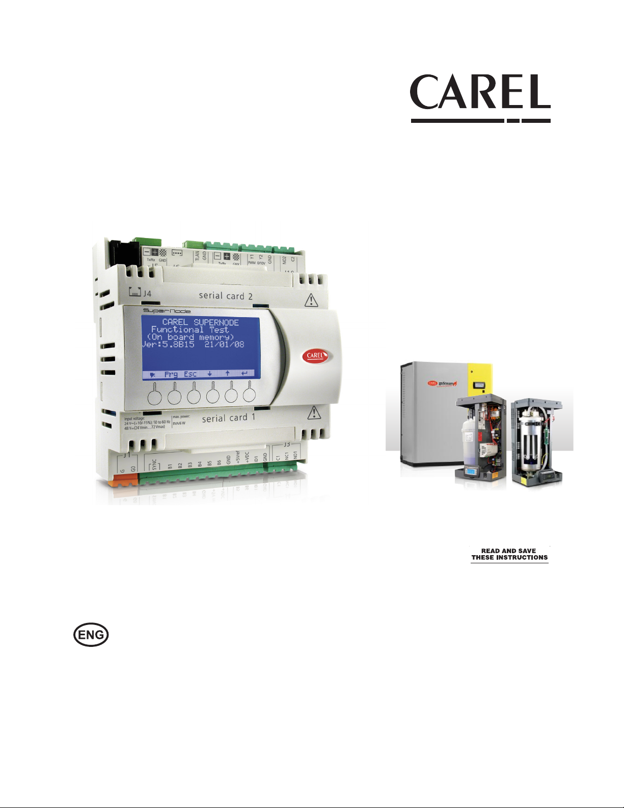
supernode
Electronic controller for humidication
Technical Leaet
Integrated Control Solutions & Energy Savings
Page 2

Symbol:
Warning: The symbol in the plastic cover of the control means to refer to this technical leaet during the electrical installation.
Page 3

ENG
1. INTRODUCTION
The gateway can connect up to a maximum of 20 devices (humiSteam X-plus, heaterSteam,
gaSteam), allowing up to 150 variables (50 analogue, 50 integer, 50 digital) for each connected
device to be managed by the external supervisor.
Seven pre-set templates allow the variables exchanged between the humidier and the gateway to
be addressed automatically, depending on the device selected during programming: simply specify
the type of device and the number of devices connected. The built-in pGD on the Supernode or an
external pGD1 terminal can be used for programming.
Supernode or Kit* part number:
Description CAREL Code
Supernode for humidication + FLSTDmUGWS (controller only) SNU0000EM0
Kit Supernode HUM BACNET MSTP SNS0000EM0 +SNSCON00M0 +PCO10B0BA0
+CVSTDUMOR0 +FLSTDMUGWS
Kit Supernode HUM BACNET ETHERNET WEB SNS0000EM0 +SNSCON00M0 +PCO10B0WB0
+FLSTDMUGWS
Kit Supernode HUM MODBUS SNS0000EM0 +SNSCON00M0 +PCOS004850 +FLSTDMUGWS A-KSNU0CL4811
A-KSNU0CLBA11
A-KSNU0CLWB11
* Note: The Supernode Communication kits contain the controller, the connectors, and the
appropriate communications card. The kit also contains a USB-Flash drive with the product manuals,
technical leaets, device guides, and the Supernode variable to unit address mapping list.
On the external supervisor side, the protocol can be selected by choosing the corresponding
optional serial card. The possible options are:
Item P/N Description
1 Modbus®/CAREL RS485 PCOS0004850 Opto-isolated RS485 serial
3 BACnet™ Ethernet™ PCO10B0WB0 Ethernet™ 8 MB serial
4 BACnet™ RS485 PCO10B0BA0 BACnet™ MS/TP 485 serial
tab. 1a
The module is DIN rail mounted, with 24 Vac power supply (+10%, -15%).
Supernode for humidication allows the possibility to select UR, UEX, and UG humidiers, including
a combination of dierent models.
For the address settings of the variables on the supervisor side, refer to the dynamic table
(included on the USB drive) the “FLSTDmUGWS_Supervisory_List_dinamic_table_supernode_for_
humidication” Excel le.
The application on Supernode also features the following options:
• Edit the humidier model, if necessary add/re-address the pre-set variables.
• Manage a generic device using the “Universal” model, which can be freely edited according to
customer requirements.
3
+08U003325 Supernode for humidication - 1.0 - 14.05.2015
Page 4
ENG
2. INSTALLATION
Install and mount the controller in a location that is appropriate for an industrial PLC.
Mechanical fastening
The Supernode is installed on a DIN rail. To fasten the unit to the DIN rail, press it lightly against the
rail. The rear tabs will click into place, locking the unit to the rail. Removing the unit is just as simple,
using a screwdriver through the release slot to lever and lift the tabs. The tabs are kept in the locked
position by springs.
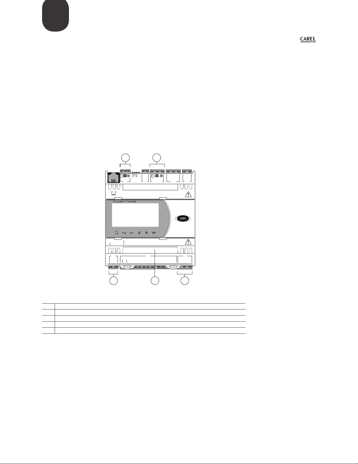
Below is a description of the connectors used for connection and installation of Supernode:
3 4
2.1 Connectors
Y2
Y1
PWM 0/10V
GNX
Tx/Rx
ISOLATED
+5Vref
+VDC
ID1
J4
C622P028/R2
input voltage: max. power:
24 V (+10/-15%); 50/60 Hz
8 VA / 6 W
48 V (36Vmin…72 Vmax)
J1
SYNC
G
G0
TLAN
GNDTx/Rx
J7
J6
serial card 2
serial card 1
B1B2B3B4B5B6GND
GND
J2
1 5 2
Key
1 power connector (G+,G0) 24 Vac or 36 V min...72 V max
2 SPDT relay digital output
3 pLAN network connector
4 optically-isolated “Field-Bus” serial connector
5 connector for BMS serial cards
GND
GNDJ3C1
C2
NO2
J10J9J8J5
NC1
NO1
+08U003325 Supernode for humidication - 1.0 - 20.06.2015
4
Page 5
ENG
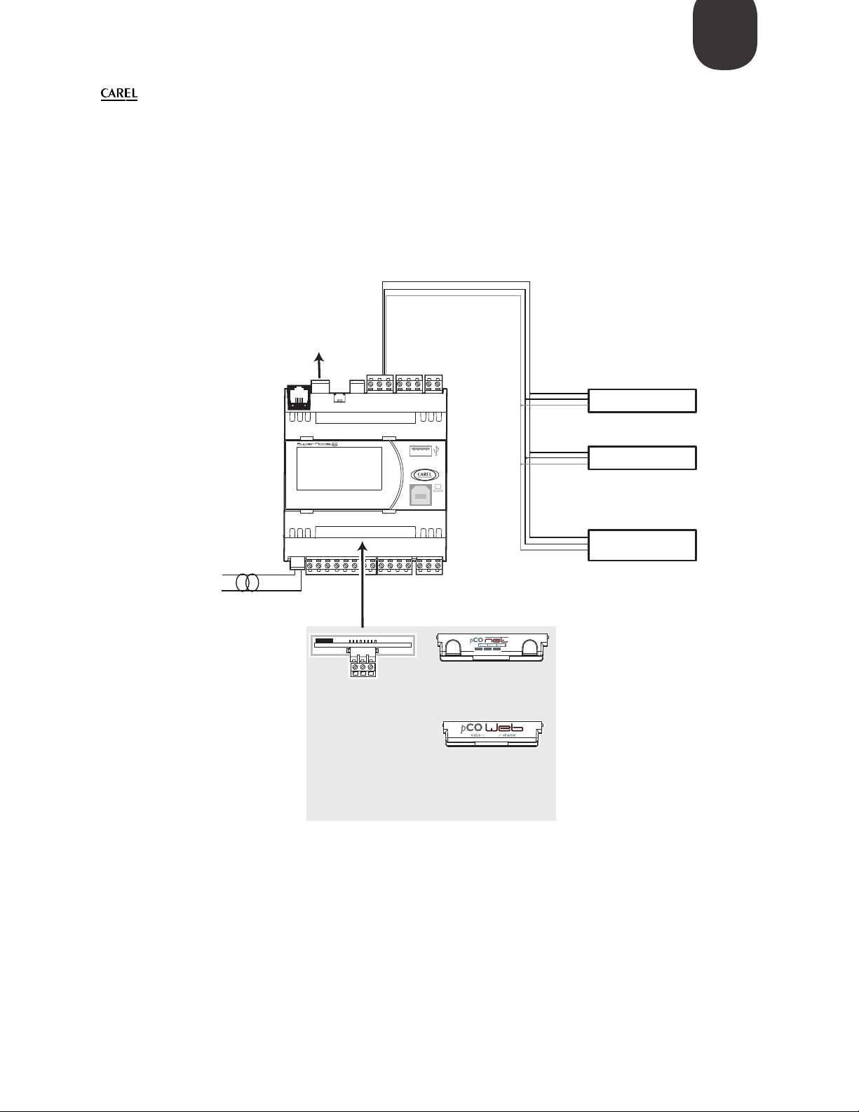
2.2 Connection diagram
Note: See each specic product/component technical leaet for specic wiring connections.
+
GND
GND
RS485
CAREL master
serial card 2
RS485
CAREL slave
+
GND
+
GND
device 1
device 2
G0
serial card 1
+
GND
device n
(n<=20)
G
BACnet™ MS/TP
status RS485
P1 P2 P3
GNX RS485+ –
PCO1000BA0
PCOS004850
RS485 serial card
BACnet™ MSTP RS485
interface
PCO1000WB0
-Ethernet™/BACnet™
interface card
5
+08U003325 Supernode for humidication - 1.0 - 14.05.2015
Page 6
ENG
Alarm
Escape
Down
Enter
3. PROGRAMMING AND CONFIGURING THE DEVICES
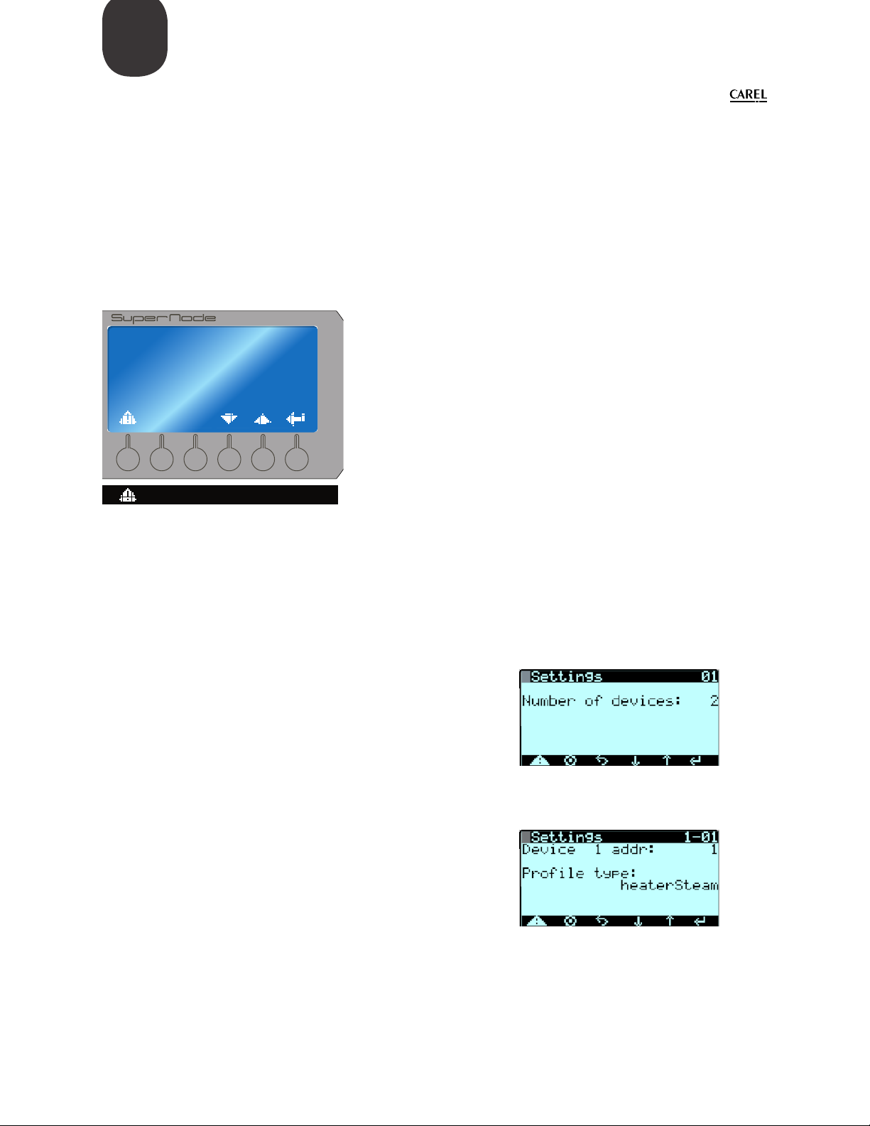
Navigation of the Display Masks
Use the “Alarm”, “Program”, “Esc”, “Down/Up”, and “Enter” keys.
Note: depending on the model of Supernode, the buttons may dier as indicated here below. In
typcial control mode, the button icons are displayed on the masks in the controller software.
PRG ESC
clear
Up
3.1 Programming the Supernode
Use Password: 1234 for entering the Service or Manufacturer menu.
1. Set the number of devices connected to the gateway:
Values available: from 1 to 20 devices.
Menu path: Service Service Settings Device settings
2. Set the address and type of device :
Models available: heaterSteam, humiSteam X-plus, gaSteam,
generic device
Menu path: Service Service Settings Device settings
The address setting and type of model must be selected for
each device connected to the gateway.
+08U003325 Supernode for humidication - 1.0 - 20.06.2015
6
Page 7
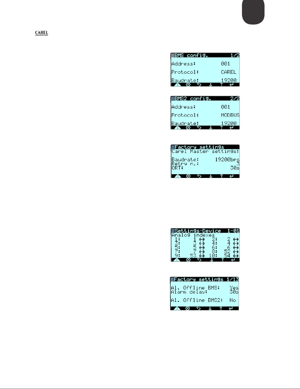
3. Set the BMS1 and BMS2 serial port for reading by
external supervisor:
Address, protocol and baud rate setting.
Menu path: Service BMS Cong.
4. Set the Carel master protocol for communication
between Supernode and devices:
ENG
Supernode communication protocol setting with devices:
baud rate (Retry n. and ORT can be left as default)
Note: the baud rate to be set always corresponds to the
slowest device connected (for heaterSteam the baud rate
is 9600).
Menu path: Manufacturer Factory Settings
5. Edit the model:
The selected model can be edited
Menu path: Manufacturer Devices cong 1-10
6. Alarm settings:
Enable alarms in the event of supervisor oine
Menu path: Manufacturer Factory Settings
7
+08U003325 Supernode for humidication - 1.0 - 14.05.2015
Page 8
ENG
3.2 Conguring the Communications Card
Each type of protocol card has dierent tools and procedures needed to setup the card.
In general, the pCOnet and pCOWeb cards need; device instance (BACnet ID), Baud Rate, The MS/TP
station address (MAC Address), and Max Master and Max frames. These settings can be congured
in 2 ways; Using BACset, or by directly in the Supernode controller screens/masks;
• Using BACset on a computer and USB/485 Converter (see guides on using MS-TP startup and
pCOnet/web cards).
• Using the pGD display on the Supernode controller (see guide on BACnet BIOS menu).
On the PGD; hold alarm & enter: other informationPCOWEB/NET CONFIGPCONET
DHCP:---
IP ADDRESS:
---.---.---.---
3.3 Conguring the humidier unit
Please reference each specic humidier product manual for supervisory control setup. For reading
of the humidier, most units will not need any settings changed. For both reading/writing (control
the humidier by BMS), each unit will need some settings changed. In general, each humidier will
have a setting for the control type and supervisory system:
• Type of control; on/o, slave-proportional, stand-alone %RH control, etc.
• Enable the humidier to be controlled by supervisory system (on/o enable, and control
regulation by BMS).
+08U003325 Supernode for humidication - 1.0 - 20.06.2015
8
Page 9
ENG
4. COMMUNICATING TO THE HUMIDIFIER(S)
The Supernode for humidication allows the possibility to select UR, UEX, and UG humidiers,
including a combination of dierent models.
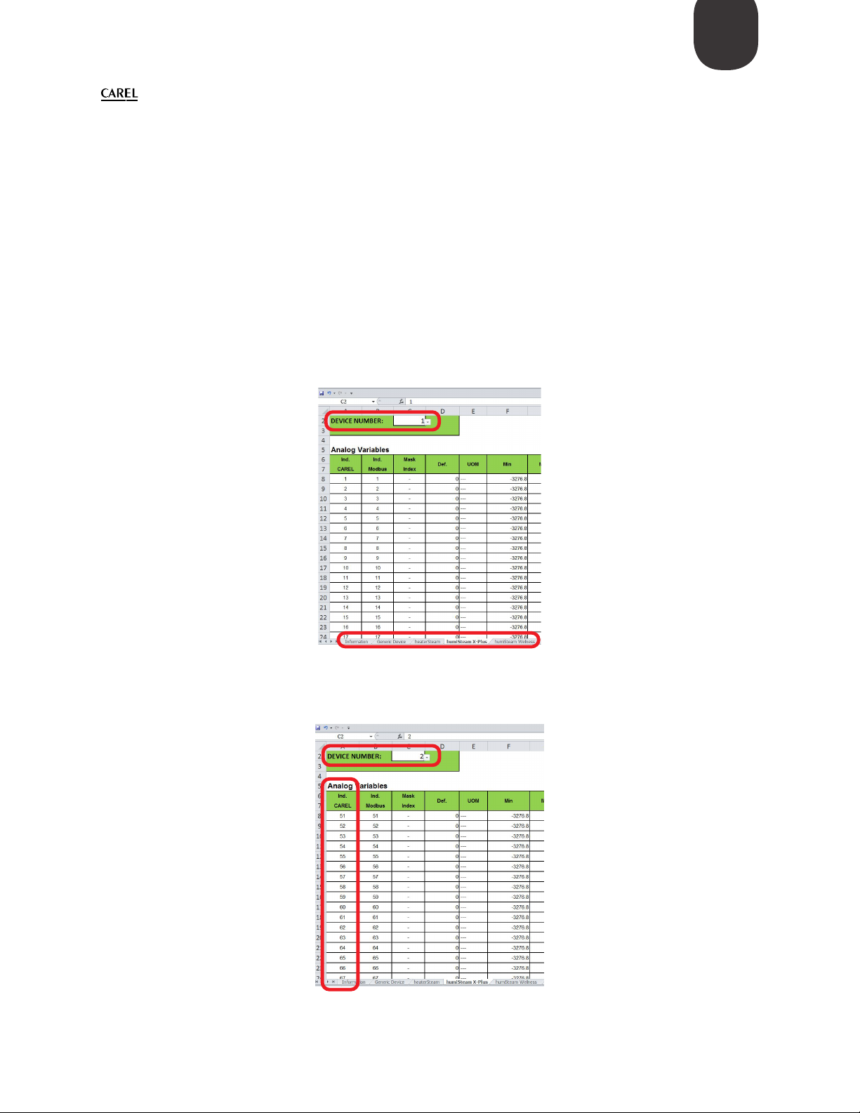
For the address settings of the variables on the supervisor side, refer to the dynamic table (included
in the USB Drive) “FLSTDmUGWS_Supervisory_List_dinamic_table_supernode_for_humidication”
Excel le. The table includes the variable list table for heaterSteam, humiSteamx-Plug, gaSteam,
and a generic device on separate tabs.
Note: When more than (1) device is in the system, use the appropriate device tab, and device
number at the top to generate the correct variable addresses.
This table can be used also for generating the variable for more than 1 device (device 2-20).
9
+08U003325 Supernode for humidication - 1.0 - 14.05.2015
Page 10

ENG
Note:
+08U003325 Supernode for humidication - 1.0 - 20.06.2015
10
Page 11

Note:
ENG
11
+08U003325 Supernode for humidication - 1.0 - 14.05.2015
Page 12
CAREL INDUSTRIES HQs
Via dell’Industria, 11 - 35020 Brugine - Padova (Italy)
Tel. (+39) 049.9716611 - Fax (+39) 049.9716600
e-mail: [email protected] - www.carel.com
CAREL USA
385 South Oak Street Manheim, PA 17545
Tel. (717) 664-0500 - Fax (717) 664-0449
e-mail: [email protected] - www.carel.com
Agenzia / Agency:
+08U003325 Supernode for humidication - 1.0 - 14.05.2015
 Loading...