

Page 1
High Efficiency Solutions
Floating suction & Smooth lines
Manuale d’uso
User manual
Plug-in PVPRO per centrali e utenze di refrigerazione
Function for pRack application, MPXPRO and PVPRO
Page 2

Page 3

3
+030220575 - 1.1 - 04.12.2014
ITA
Indice
1. INTRODUZIONE 5
1.1 Smooth lines su MPXPRO: funzionamento ...............................................................................................................................5
1.2 Smooth lines su MPXPRO: confi gurazione ................................................................................................................................6
1.3 Floating suction su pRack ....................................................................................................................................................................7
1.4 Floating suction su PVPRO ..................................................................................................................................................................8
2. CONFIGURAZIONE FS SU PVPRO 9
2.1 Selezione rack ..............................................................................................................................................................................................9
2.2 Abbinamento rack ....................................................................................................................................................................................9
2.3 Maschera principale ............................................................................................................................................................................. 10
2.4 Maschera Principale: confi gurazione e funzionamento (con Smooth lines) .................................................... 11
2.5 Maschera Principale: dettagli di funzionamento (con Smooth lines) ................................................................... 12
2.6 Maschera Principale: confi gurazione e funzionamento (senza Smooth lines) ............................................. 13
2.7 Maschera Principale: dettagli di funzionamento (senza Smooth lines) ............................................................... 14
Page 4

Page 5
5
+030220575 - 1.1 - 04.12.2014
ITA
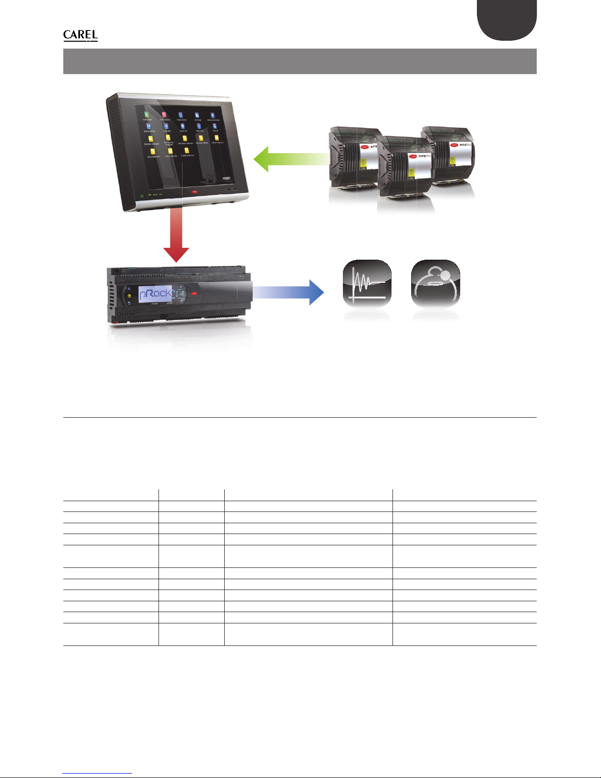
Fig. 1.a
1.1 Smooth lines su MPXPRO: funzionamento
L’obiettivo principale della funzione Smooth lines, disponibile sulla versione di MPXPRO 3.2 e successive, è
di mantenere la temperatura dell’utenza estremamente stabile intorno al setpoint, evitando frequenti cicli
di accensione/spegnimento della richiesta di refrigerazione. I parametri interessati dalla confi gurazione della
Smooth lines sono elencati nella tabella che segue:
Nome parametro Menu Descrizione Visibilità
St CtL Setpoint di regolazione PVPRO & interfaccia utente
rd CtL Diff erenziale di regolazione PVPRO & interfaccia utente
P3 Eud Setpoint di surriscaldamento PVPRO & interfaccia utente
PHS Eud Off set di surriscaldamento PVPRO & interfaccia utente
PLt Eud Off set di regolazione al di sotto del
setpoint
PVPRO & interfaccia utente
PSI Eud Tempo integrale PVPRO & interfaccia utente
PSM Eud Abilitazione funzione PVPRO & interfaccia utente
PSP Eud Guadagno proporzionale PVPRO & interfaccia utente
PSd - Tempo derivativo PVPRO
TSH - Soglia di surriscaldamento PVPRO
FSt - Finestra temporale per calcolo media
surriscaldamento
PVPRO
Tab. 1.a
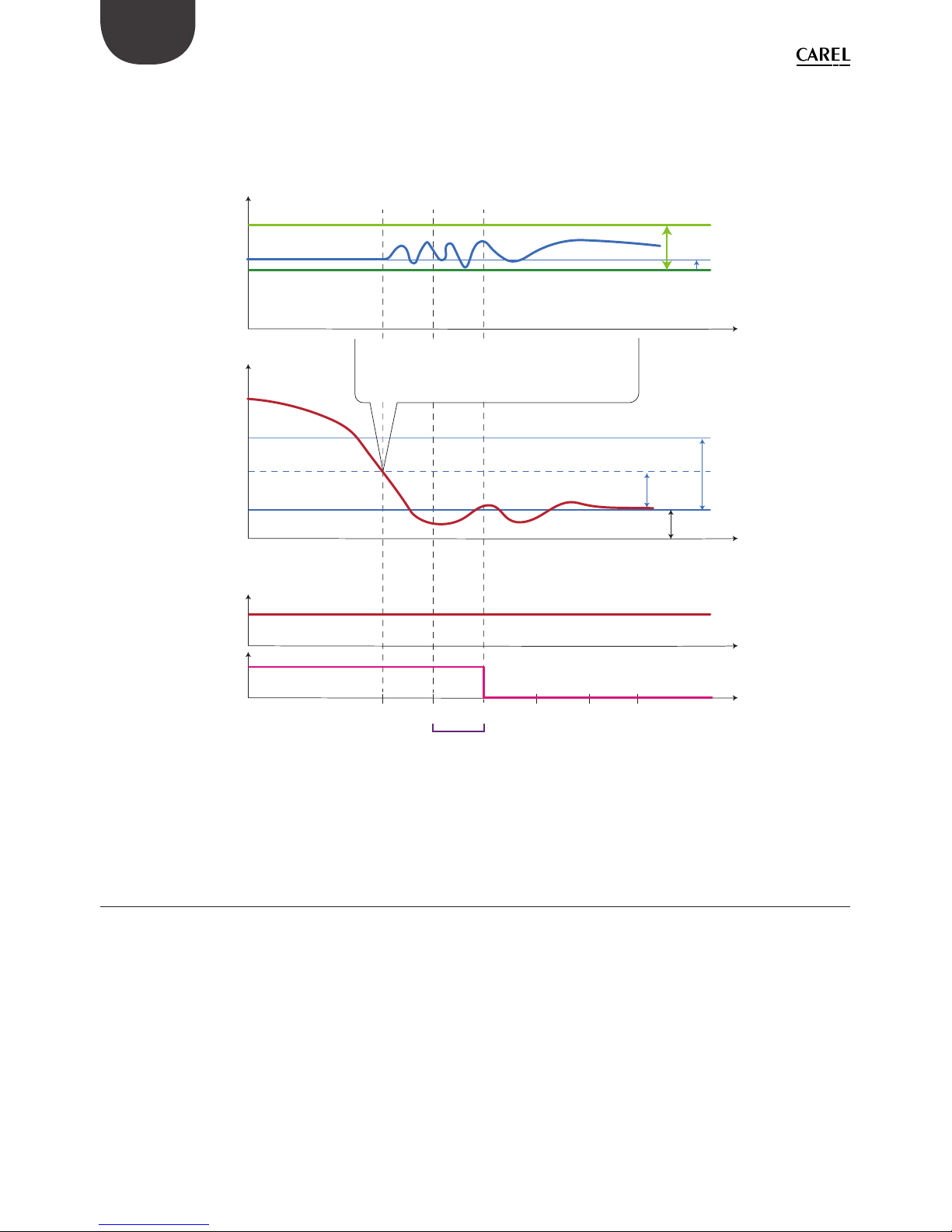
La funzione opera come segue: quando la temperatura di controllo raggiunge il setpoint + metà del differenziale, la refrigerazione non viene fermata, ed uno speciale algoritmo PID aumenta il setpoint di surriscaldamento per modulare la valvola di espansione. Questo speciale algoritmo si applica fi no a quando la
temperatura di controllo non scende al di sotto della soglia St – PLt.
1. INTRODUZIONE
Page 6
6
+030220575 - 1.1 - 04.12.2014
ITA
Se la funzione Smooth lines è abilitata, l’algoritmo indica al supervisore se l’MPXPRO sta funzionando con un
determinato margine, cioè se il setpoint della pressione della linea di aspirazione corrispondente può essere
aumentato senza pregiudicare la regolazione. In dettaglio, MPXPRO dichiara che il funzionamento è idoneo
se il setpoint di surriscaldamento medio è superiore a P3 + THS. La media viene calcolata all’interno della
fi nestra temporale FSt.
Working setpoint
Superheat setpoint (P3)
Regulation setpoint
Regulation temperature
Cooling request
Smooth line status
FSt = average time window (min)
1
0
tt1t2t3t4t5
1
0
PLt = offset under setpoint
When the average of working setpoint is higher
than the threshold P3 + TSH the Smooth line status
becomes 0, allowing suction pressure rising.
rd = setpoint differential
rd/2
TSH = superheat threshold
PHS = max superheat offset
As soon as the regulation temperature falls below the
setpoint + rd/2, an offset will be added to the superheat
setpoint in order to reduce the EXV valve opening.
Cooling status will stay active until the regulation
tewmperature does not fall below the threshold St - PLt.
Fig. 1.b
1.2 Smooth lines su MPXPRO: con gurazione
I parametri di confi gurazione della Smooth lines sono elencati nella Tabella 1. Le impostazioni basilari sono
elencate di seguito, con il nome del parametro ed il valore di default:
1. abilitazione funzione, il valore di default è PSM = 0 (disabilitata);
2. impostazione off set surriscaldamento massimo, il valore di default è PHS = 15 (K);
3. impostazione off set di regolazione sotto al setpoint, il valore di default è PLt = 2 (K);
4. impostazione del diff erenziale di controllo principale, il valore di default è rd = 2 (K);
se è abilitata la Smooth lines, il valore consigliato è rd = 4 (K).
Page 7
7
+030220575 - 1.1 - 04.12.2014
ITA
1.3 Floating suction su pRack
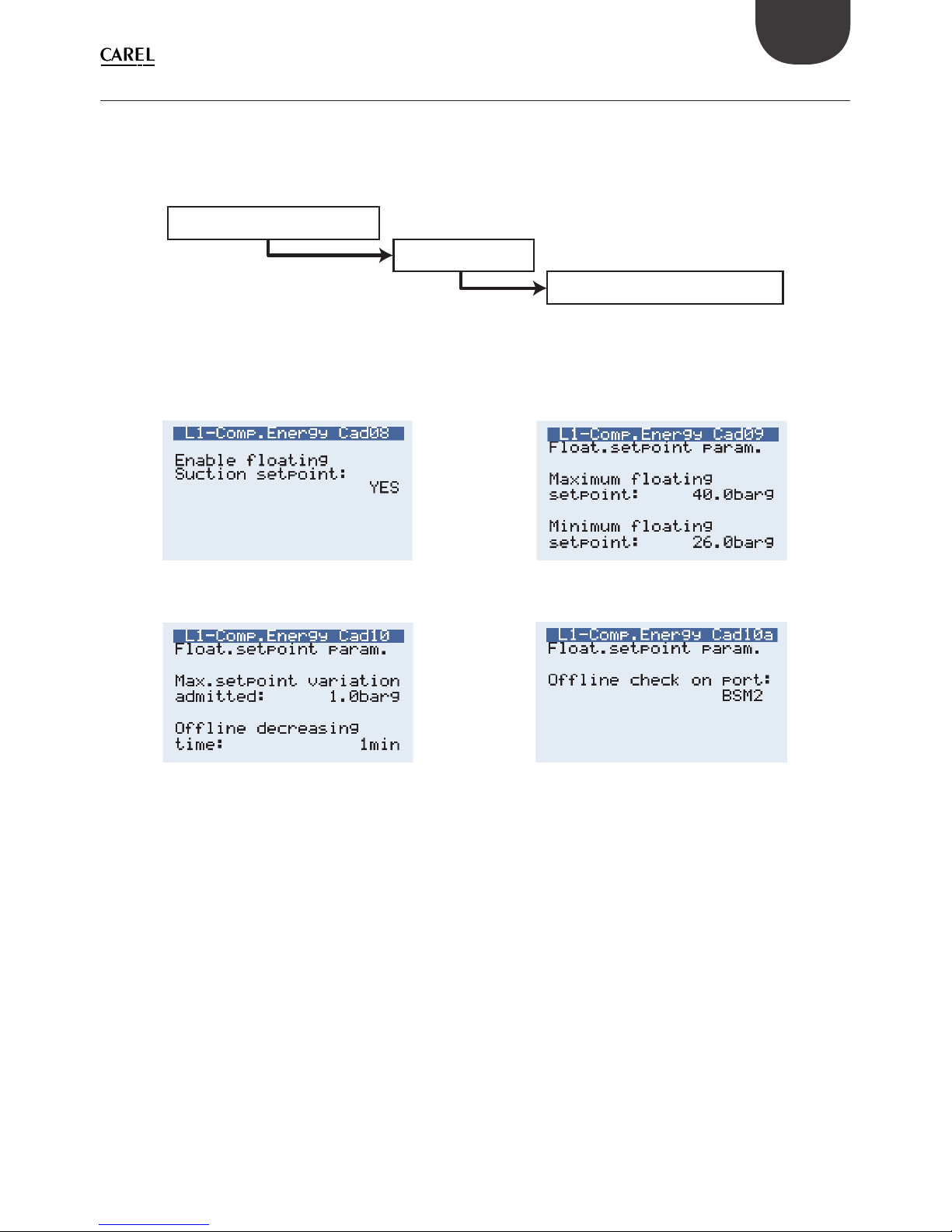
L’applicazione pRack dispone della funzione Floating suction che consente al plug-in PVPRO di aumentare il
setpoint della pressione di aspirazione quando le condizioni di funzionamento delle utenze sono favorevoli.
Il percorso di confi gurazione è il seguente:
C. Compressors
d. Energy saving
a. Line 1
Fig. 1.c
Questo percorso si riferisce alla linea di aspirazione 1, per la linea 2 la confi gurazione è similare ed il percorso
è: C.Compressors d.Energy saving
Fig. 1.d Fig. 1.e
Fig. 1.f Fig. 1.g
Dopo essere entrati nel menu di confi gurazione, la schermata Cad08 viene utilizzata per abilitare la funzione
Floating suction.
Le schermate Cad09 e Cad10 sono utilizzate per specifi care i parametri di funzionamento: il setpoint
minimo e massimo defi niscono l’intervallo in cui il setpoint di funzionamento può essere modifi cato dal
plug-in Floating suction in funzione su PVPRO.
Esiste anche la possibilità di defi nire il gradiente di aumento e diminuzione per ciascuna variazione, ed
un tempo specifi co per diminuire il setpoint se viene persa la comunicazione con PVPRO . La porta per il
monitoraggio dell’interruzione della comunicazione viene defi nita nella schermata Cad10a.
Page 8
8
+030220575 - 1.1 - 04.12.2014
ITA
1.4 Floating suction su PVPRO
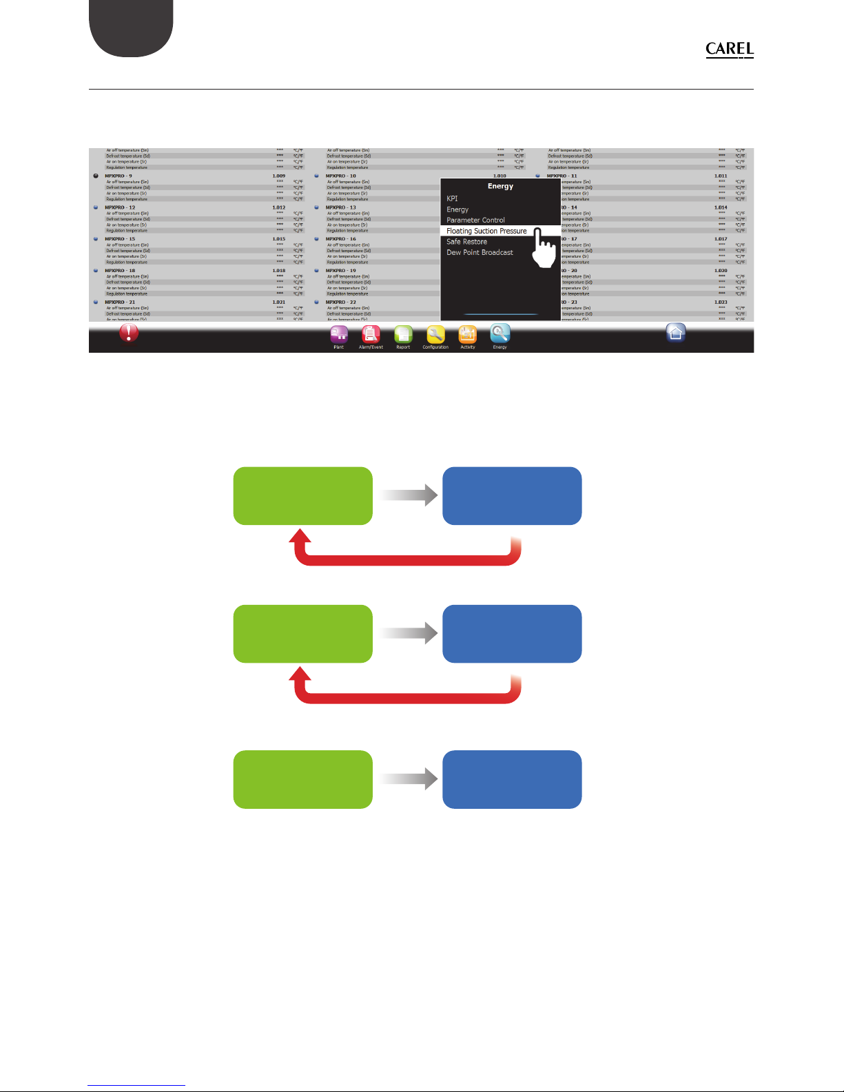
PVPRO dispone della funzione Floating suction, che può essere abilitata e confi gurata facendo clic sul menù
“Ottimizzazione Pressione Aspirazione” nel menù Energia, come illustrato nella Figura 1.h.
Fig. 1.h
Può essere utilizzata sia su utenze dotate dell’algoritmo Smooth lines sia su utenze senza questa funzione (es.
IR33, MPXPRO versione < 3.2). Utilizzare la presente linea guida per scegliere l’opzione più idonea:
MPXPRO* only
Floating suction
on PVPRO with
Smooth line ag
Floating suction on
PVPRO without
Smooth line ag
Floating suction on
PVPRO without
Smooth line ag
Mix of MPXPRO*
and other utilities
Other than
MPXPRO*
utilities only
Enable Smooth line on MPXPRO
Disable Smooth line on MPXPRO
Fig. 1.i
* MPXPRO ver. 3.2 o successiva.
Page 9
9
+030220575 - 1.1 - 04.12.2014
ITA
2. CONFIGURAZIONE FS SU PVPRO
Dopo essere entrati nel menu “Ottimizzazione Pressione Aspirazione” il plug-in viene confi gurato in varie fasi,
a partire dall’ultima scheda a destra fi no alla prima a sinistra.
2.1 Selezione rack
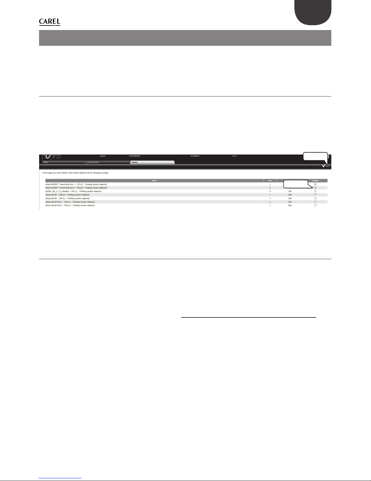
Nella scheda “Centrali”, scegliere quali rack abilitare per la funzione Floating suction.
Procedura di confi gurazione:
1. spuntare la caselle relativa ai dispositivi interessati;
2. fare clic su “Salva” nell’angolo in alto a destra.
La procedura di confi gurazione è illustrata nella Figura 2.a.
STEP 2
STEP 1
Fig. 2.a
2.2 Abbinamento rack
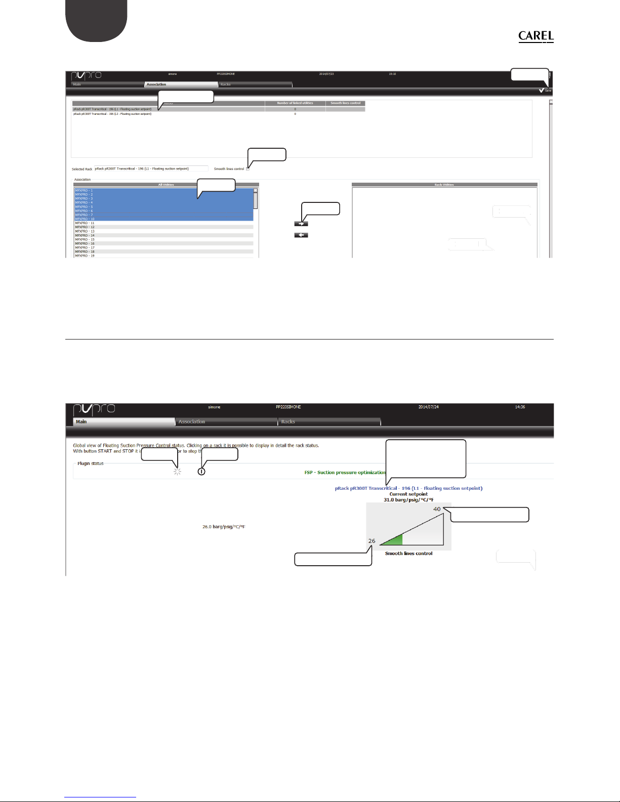
Se c’è almeno un rack selezionato per la funzione Floating suction è possibile abbinare al rack diverse utenze.
Ogni rack può avere più di una utenze abbinata; tuttavia ogni utenza può essere abbinata ad un solo rack.
Nella scheda “Associazione” procedere come segue:
1. fare doppio clic su un rack compressore; il nome relativo verrà illustrato nella casella di testo “Centrale
selezionata”;
2. selezionare i dispositivi dall’elenco a sinistra;
3. spuntare la casella “Funzione Smooth lines” solo se tutti i dispositivi sono dotati di questa funzione;
4. fare clic sulla freccia DESTRA per abbinare le utenze con il rack;
5. fare clic su “Salva” nell’angolo in alto a destra.
Page 10
10
+030220575 - 1.1 - 04.12.2014
ITA
La procedura di confi gurazione è illustrata nella Figura 2.b.
STEP 2
STEP 1
STE
P 2
STE
P 1
doble click
STEP 2
STEP 3
STEP 4
STEP 5
Fig. 2.b
2.3 Maschera principale
La scheda “Principale” mostra tutti i rack compressori selezionati per la funzione Floating suction. Un triangolo
rappresenta lo stato di modifi ca del setpoint, dal valore minimo a quello massimo.
In questa scheda, gli utenti possono abilitare o disabilitare il plug-in, accedere alla pagina di confi gurazione
ed alla pagina di monitoraggio relativa a ciascun rack.
STEP 2
STEP 2
START STOP
Enter conguration
and monitoring
pages
Minimum setpoint
Maximum setpoint
Fig. 2.c
Dalla scheda “Principale” facendo clic sulla descrizione pRack (blu), gli utenti possono accedere alla vista di
confi gurazione e monitoraggio del plug-in.
Queste due schermate sono visualizzate in modo diverso, a seconda del fatto che le utenze associate siano
dotate della funzione Smooth lines, vale a dire se è stata o meno creata l’associazione con il fl ag Smooth lines
spuntato (per i dettagli vedere il paragrafo 2.2).
Page 11
11
+030220575 - 1.1 - 04.12.2014
ITA
2.4 Maschera Principale: con gurazione e funzionamento (con
Smooth lines)
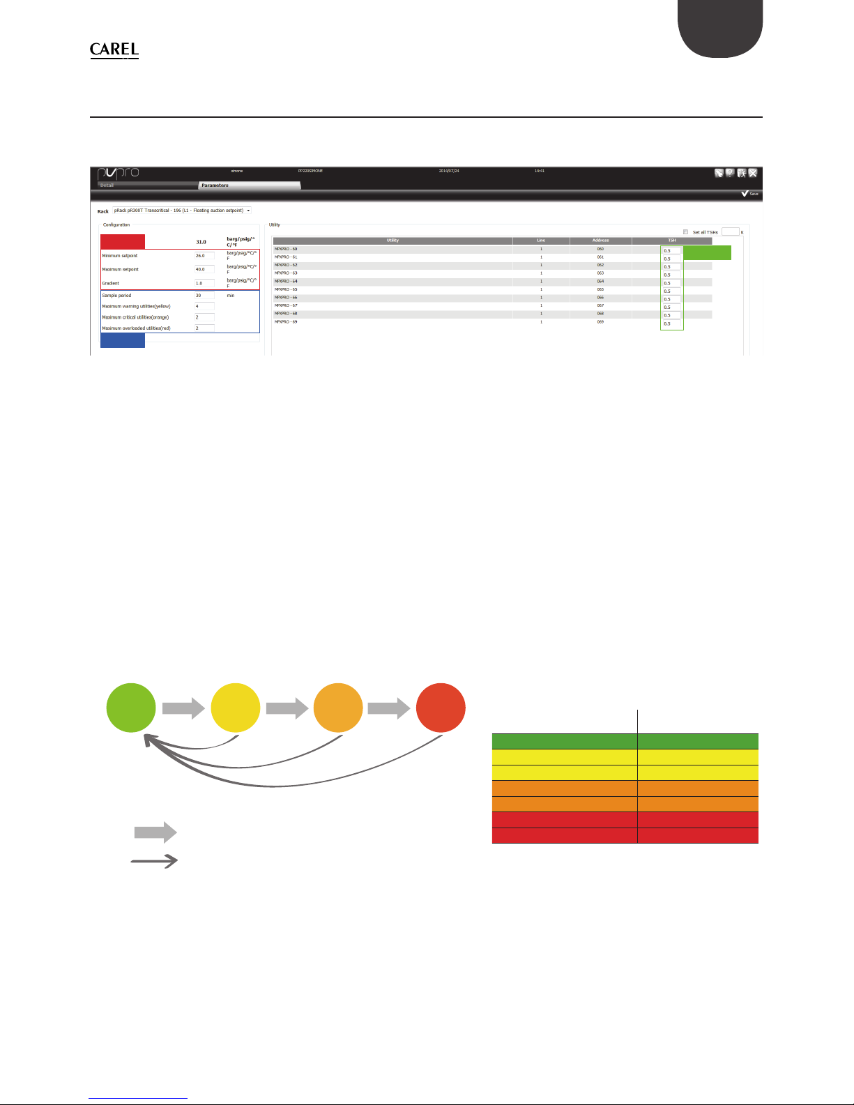
La scheda “Parametri” mostra le impostazioni del plug-in: possono essere suddivise in tre gruppi, a seconda
di quali sono i dispositivi a cui si riferiscono: pRack, PVPRO e utenze.
pRack
PVPRO
Utilities
Fig. 2.d
La sezione di confi gurazione pRack riporta i valori dei parametri impostati su pRack (vedere paragrafo 1.3
per i dettagli).
Le impostazioni PVPRO fanno riferimento ai parametri del motore del plug-in. È possibile specifi care il periodo
di campionamento, cioè la frequenza di ogni potenziale azione di aumento o diminuzione del setpoint della
pressione di aspirazione e le regole per stabilire se eseguire un’azione o il suo opposto.
Ci sono tre soglie associate a tre colori: giallo, arancione e rosso. Il colore di partenza, il verde, viene usato per
indicare le utenze con funzionamento idoneo, laddove cioè la regolazione consente l’aumento del setpoint
della pressione di aspirazione.
Lo stato (colore) delle utenze viene valutato ad ogni campionamento. Le regole che defi niscono il
monitoraggio dello stato sono illustrate nella Figura 2.e.
Osservando il numero di utenze con lo stesso colore e le soglie relative a ciascun colore, i criteri per variare il
setpoint sono descritti nella tabella seguente:
Utility is working hard: there is no margin
to rise up suction pressure setpoint
Utility is working ne: reset status
Unit condition Action on set point
all green increase
# of yellow < threshold increase
# of yellow ≥ threshold hold
# of orange < threshold increase
# of orange ≥ threshold hold
# of red > 0 hold (*)
# of red ≥ threshold decrease
(*) if the number of red ones is lower than the
red threshold.
Fig. 2.e
Viene riservato un trattamento speciale alle utenze che sono offl ine e alle utenze che non sono dotate della
funzione Smooth lines, ma che sono state abbinate erroneamente, con il fl ag Smooth lines spuntato.
Se un’utenza non è disponibile (offl ine per PVPRO) dopo il tempo di campionamento verrà indicata in nero
e considerata come fosse non disponibile per l’aumento del setpoint di pressione. Questa utenza viene
considerata come se fosse gialla, arancione o rossa a seconda di quante volte è stata dichiarata offl ine.
Page 12
12
+030220575 - 1.1 - 04.12.2014
ITA
Se un’utenza è stata abbinata erroneamente come dispositivo dotato di Smooth lines ma in realtà non è
dotata di questa funzione, PVPRO non rileverà le condizioni di funzionamento di questo dispositivo e lo
indicherà come N/A (non disponibile). Poichè la modifi ca del setpoint della pressione di aspirazione può
infl uenzare il controllo della linea di aspirazione e PVPRO non conosce le condizioni di funzionamento
dell’utenza, il plug-in resetterà il setpoint al valore minimo.
Questi due scenari particolari sono illustrati nella Figura 2.f.
Y N/A
yellow
orange
O
red
R
if an utility is market as N/A, it means
it doesn’t feature the Smooth line
functionality and any setpoint
increment will be reset.
Fig. 2.f
2.5 Maschera Principale: dettagli di funzionamento (con Smooth
lines)
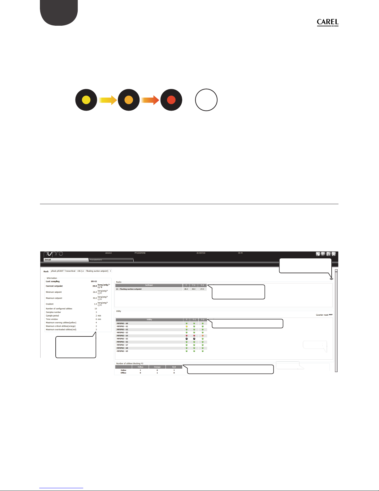
Nella scheda “Dettagli” gli utenti possono avere una rassegna dettagliata dello stato dell’utenza. Viene
mostrato un riassunto delle impostazioni, sia relative a PVPRO sia a pRack, ed il valore del setpoint di
funzionamento, con alcuni campioni storici.
In fondo alla pagina, una tabella riporta il conteggio delle utenze per ciascun colore, suddivise tra online e
offl ine.
STEP 2
S
TEP
2
Summary table
with plug-in
settings
Summary table with colour counting
Main table with utilities status
Current setpoint
and historical values
Click here to enlarge
the historical view
Fig. 2.g
Page 13
13
+030220575 - 1.1 - 04.12.2014
ITA
2.6 Maschera Principale: con gurazione e funzionamento (senza
Smooth lines)
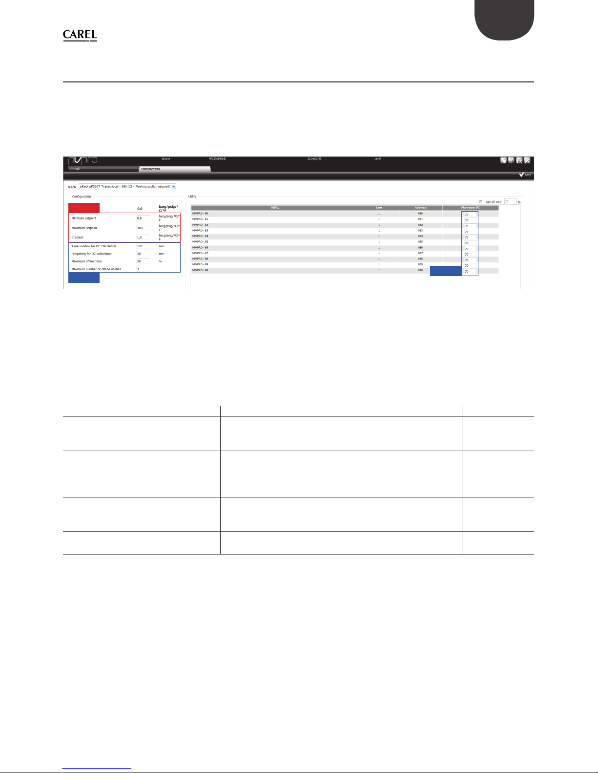
In un gruppo di utenze, se alcune o tutte non sono dotate della funzione Smooth lines, il fl ag Smooth lines
non dovrebbe essere spuntato durante la fase di associazione (vedere paragrafo 2.2 per i dettagli). Per questo
gruppo, la pagina di confi gurazione apparirà come illustrato nella Figura 2.h.
Poichè le utenze non sono dotate di nessuna funzione di regolazione speciale, da PVPRO l’utente può
confi gurare solo i parametri relativi al supervisore stesso ed al rack.
pRack
PVPRO
PVPRO
Fig. 2.h
In questo caso, la logica del plug-in si basa sul ciclo di esercizio delle utenze: se la percentuale misurata è
maggiore della soglia confi gurata si considera che la linea non abbia alcun margine per aumentare il setpoint
della pressione di aspirazione. La soglia viene defi nita inserendo una percentuale per ciascuna utenza nella
colonna “DC massimo” (ciclo di esercizio massimo).
La tabella che segue riporta il signifi cato delle impostazioni PVPRO ed i relativi valori di default.
Parametro Descrizione Valore di default
Finestra temporale per il calcolo del DC Il ciclo di esercizio dell'utenza verrà calcolato nell'ambito di
questa fi nestra temporale. Il valore può variare da 10 a 180
minuti.
120 minuti
Frequenza per calcolo del DC Indica la frequenza della potenziale azione sul setpoint: alla
fi ne di ciascun periodo, il ciclo di esercizio calcolato verrà
confrontato con la soglia per aumentare o diminuire il
setpoint. Il valore può variare da 10 a 180 minuti.
30 minuti
Tempo massimo di mancata connessione
Percentuale massima di rilevamenti mancati per ogni utenza
abbinata con il rack. Se viene superato questo valore l'utenza
viene considerata offl ine.
30%
Numero massimo di utenze non
connesse
Se il numero di utenze offl ine supera questo numero il
setpoint della pressione di aspirazione non verrà modifi cato.
3
Tab. 2.a
Page 14
14
+030220575 - 1.1 - 04.12.2014
ITA
2.7 Maschera Principale: dettagli di funzionamento (senza Smooth
lines)
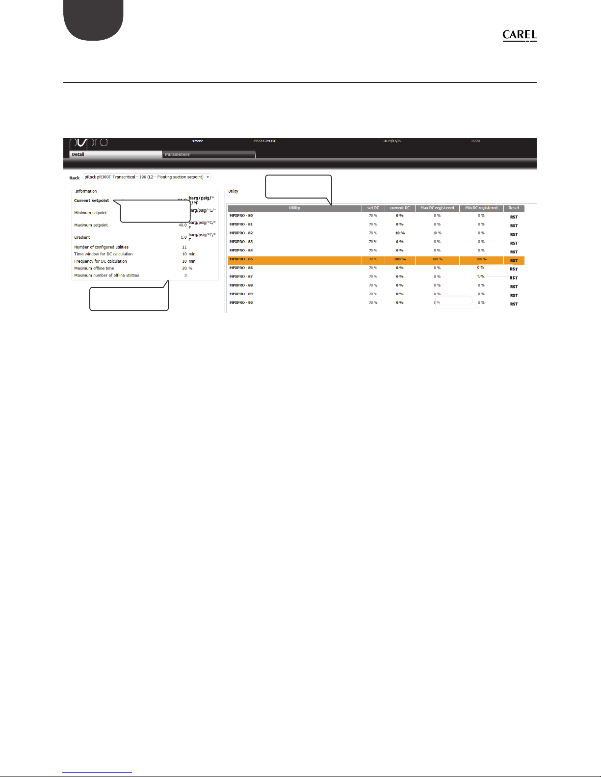
Nella scheda “Dettaglio” gli utenti possono avere una panoramica dettagliata dello stato delle utenze. E’
riportato un riassunto delle impostazioni, sia relative al PVPRO sia al pRack, il valore del setpoint ed una
tabella con i valori del ciclo di esercizio corrente, massimo e minimo registrato da PVPRO ad ogni rilevazione.
STEP 2
STEP 1
STEP 2
S
TEP
1
Summary table with
plug-in settings
Current suction
pressure setpoint
Main table with
utilities status
Fig. 2.i
Page 15

3
+030220575 - 1.1 - 04.12.2014
ENG
Content
1. INTRODUCTION 5
1.1 Smooth lines on MPXPRO: how it works ....................................................................................................................................5
1.2 Smooth lines on MPXPRO: confi guration ..................................................................................................................................6
1.3 Floating suction on pRack ...................................................................................................................................................................7
1.4 Floating suction on PVPRO ................................................................................................................................................................. 8
2. FS CONFIGURATION ON PVPRO 9
2.1 Rack selection ..............................................................................................................................................................................................9
2.2 Rack association ......................................................................................................................................................................................... 9
2.3 Dashboard: main view ........................................................................................................................................................................ 10
2.4 Dashboard: confi guration view and logic (with Smooth lines).................................................................................11
2.5 Dashboard: monitoring view (with Smooth lines) ............................................................................................................12
2.6 Dashboard: confi guration view and logic (without Smooth lines) ......................................................................... 13
2.7 Dashboard: monitoring view (without Smooth lines) .................................................................................................... 14
Page 16

Page 17
5
+030220575 - 1.1 - 04.12.2014
ENG
Fig. 1.a
1.1 Smooth lines on MPXPRO: how it works
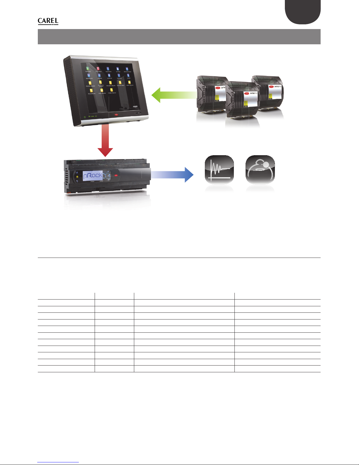
The main target of the Smooth lines function, available on MPXPRO version 3.2 and higher, is to keep the
control temperature very stable around the set point, avoiding frequent ON/OFF cycles of cooling request.
The parameters involved in the Smooth lines confi guration are listed in the following table:
Parameter name Menu Description Visibility
St CtL Control set point PVPRO & User interface
rd CtL Control diff erential PVPRO & User interface
P3 Eud Superheat set point PVPRO & User interface
PHS Eud Positive SH off set PVPRO & User interface
PLt Eud Off set below set point for cut-off PVPRO & User interface
PSI Eud Integral time PVPRO & User interface
PSM Eud Enable function PVPRO & User interface
PSP Eud Proportional coeffi cient PVPRO & User interface
PSd - Derivative time PVPRO
TSH - Superheat threshold PVPRO
FSt - Superheat averaging time window PVPRO
Tab. 1.a
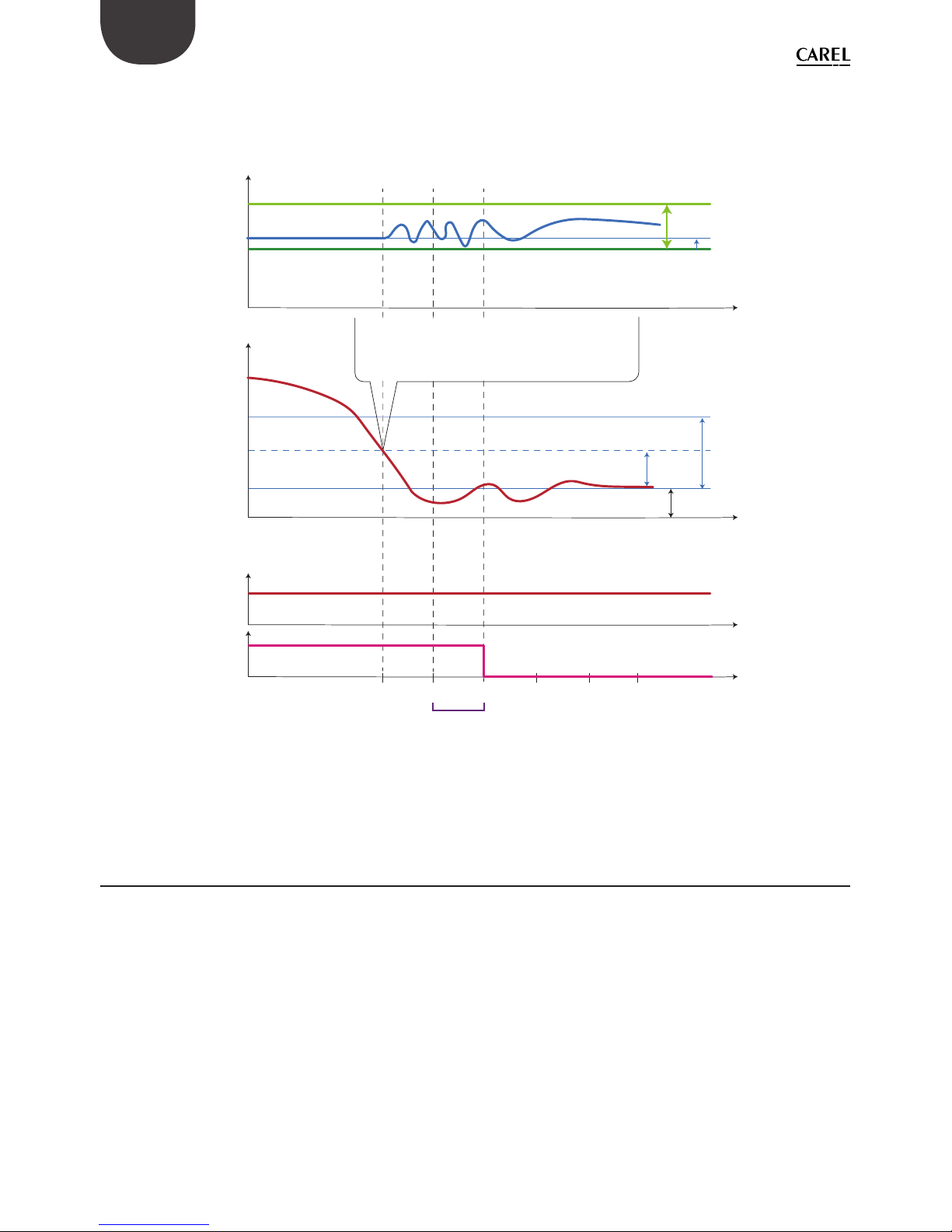
The function works as follows: when the control temperature reaches the set point + half of the diff erential,
the control is not stopped, and a special PID algorithm increases the working superheat set point in order
to modulate the expansion valve. This special algorithm works until the control temperature exceeds St –
PLt.
1. INTRODUCTION
Page 18
6
+030220575 - 1.1 - 04.12.2014
ENG
If the Smooth lines function is enabled, the algorithm tells the supervisor whether the MPXPRO is operating
with a certain margin, i.e., the suction pressure set point on the corresponding line can be increased without jeopardising control. In detail, the MPXPRO declares that operation is suitable if the average working
superheat set point is higher than P3 + THS. The average is calculated inside the time window FSt.
Working setpoint
Superheat setpoint (P3)
Regulation setpoint
Regulation temperature
Cooling request
Smooth line status
FSt = average time window (min)
1
0
tt1t2t3t4t5
1
0
PLt = offset under setpoint
When the average of working setpoint is higher
than the threshold P3 + TSH the Smooth line status
becomes 0, allowing suction pressure rising.
rd = setpoint differential
rd/2
TSH = superheat threshold
PHS = max superheat offset
As soon as the regulation temperature falls below the
setpoint + rd/2, an offset will be added to the superheat
setpoint in order to reduce the EXV valve opening.
Cooling status will stay active until the regulation
tewmperature does not fall below the threshold St - PLt.
Fig. 1.b
1.2 Smooth lines on MPXPRO: con guration
The Smooth lines confi guration parameters are listed in Table 1. The basic settings are listed below, with the
parameter name and default value:
1. enable function, default value is PSM = 0 (disabled);
2. set maximum superheat off set, default value is PHS = 15 (K);
3. set compressor cut-off off set, default value is PLt = 2 (K);
4. set main control diff erential, default value is rd = 2 (K);
if smooth lines is enabled, the suggested value is rd = 4 (K).
Page 19
7
+030220575 - 1.1 - 04.12.2014
ENG
1.3 Floating suction on pRack
The pRack application features the Floating suction function, allowing the PVPRO plug-in to increase the
suction pressure set point when the unit operating conditions are favourable.
The confi guration path is as follows :
C. Compressors
d. Energy saving
a. Line 1
Fig. 1.c
This path refers to suction Line 1, Line 2 is confi gured in the same way. If the rack manages one suction line
only, the path will be: C.Compressors d.Energy saving
Fig. 1.d Fig. 1.e
Fig. 1.f Fig. 1.g
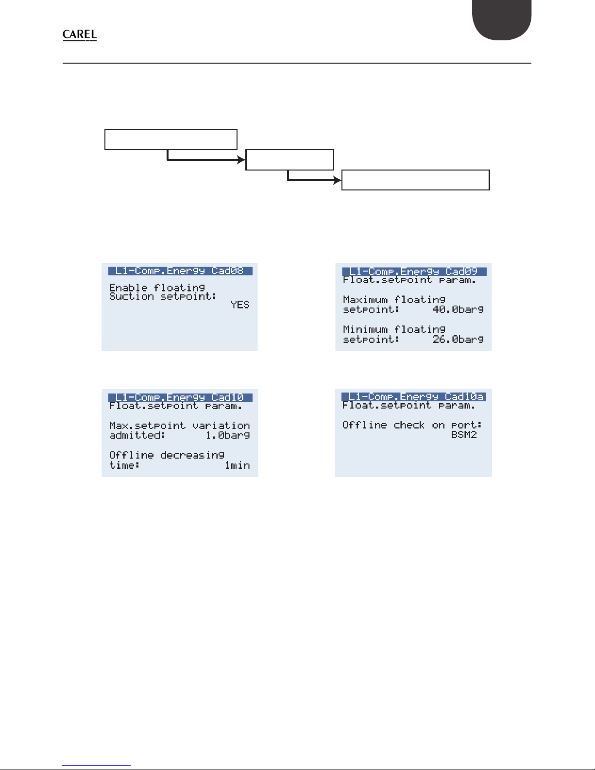
Once having entered the confi guration menu, screen Cad08 is used to enable the Floating suction function.
Screens Cad09 and Cad10 are used to specify the operating parameters: the maximum and minimum set
point establish the range within which the working set point can be moved by the Floating suction plug-in
running on PVPRO.
There is also the possibility to defi ne the increase and decrease step for each variation, and a specifi c time
for decreasing the set point if communication is lost with PVPRO . The port for monitoring communication
failure is defi ned in screen Cad10a.
Page 20
8
+030220575 - 1.1 - 04.12.2014
ENG
1.4 Floating suction on PVPRO
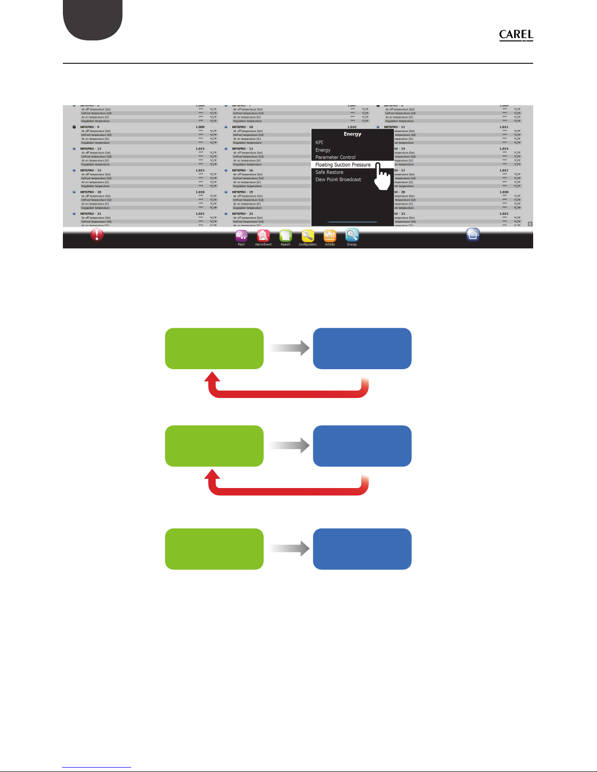
PVPRO features the Floating suction function, which can be enabled and confi gured by clicking the Floating
Suction Pressure menu from the Energy plugins, as shown in Figure 1.h.
Fig. 1.h
This can be used both on units featuring the Smooth line algorithm, and on units without this function (e.g.
IR33, MPXPRO version < 3.2). Please use this guideline to choose the most suitable option:
MPXPRO* only
Floating suction
on PVPRO with
Smooth line ag
Floating suction on
PVPRO without
Smooth line ag
Floating suction on
PVPRO without
Smooth line ag
Mix of MPXPRO*
and other utilities
Other than
MPXPRO*
utilities only
Enable Smooth line on MPXPRO
Disable Smooth line on MPXPRO
Fig. 1.i
* MPXPRO ver. 3.2 or later.
Page 21
9
+030220575 - 1.1 - 04.12.2014
ENG
2. FS CONFIGURATION ON PVPRO
Once having entered the Floating Suction Pressure menu, the plug-in is confi gured in several steps, starting
from the last tab on the right, to the fi rst on the left.
2.1 Rack selection
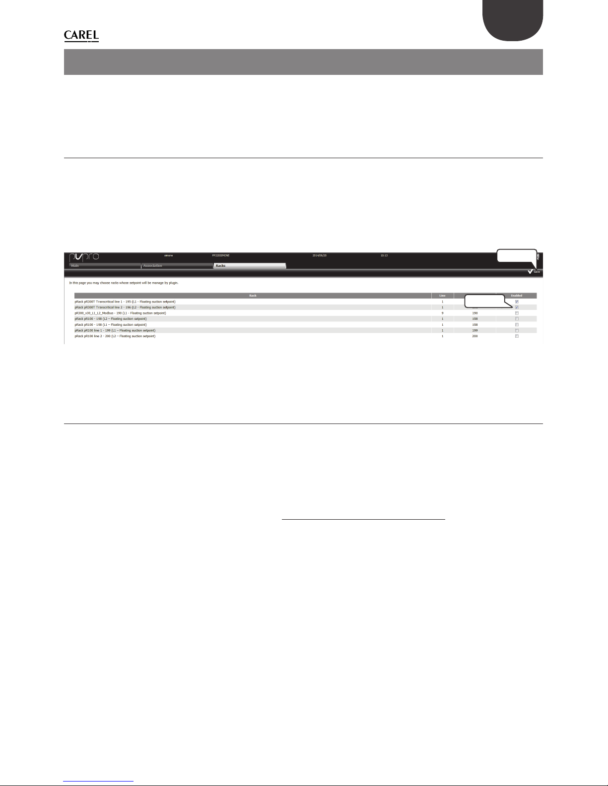
In the “Racks” tab, choose which racks to enable for the Floating suction function.
Confi guration procedure:
1. tick the checkbox relating to the desired devices;
2. click “Save” in the top-right corner.
The confi guration procedure is illustrated in Figure 2.a.
STEP 2
STEP 1
Fig. 2.a
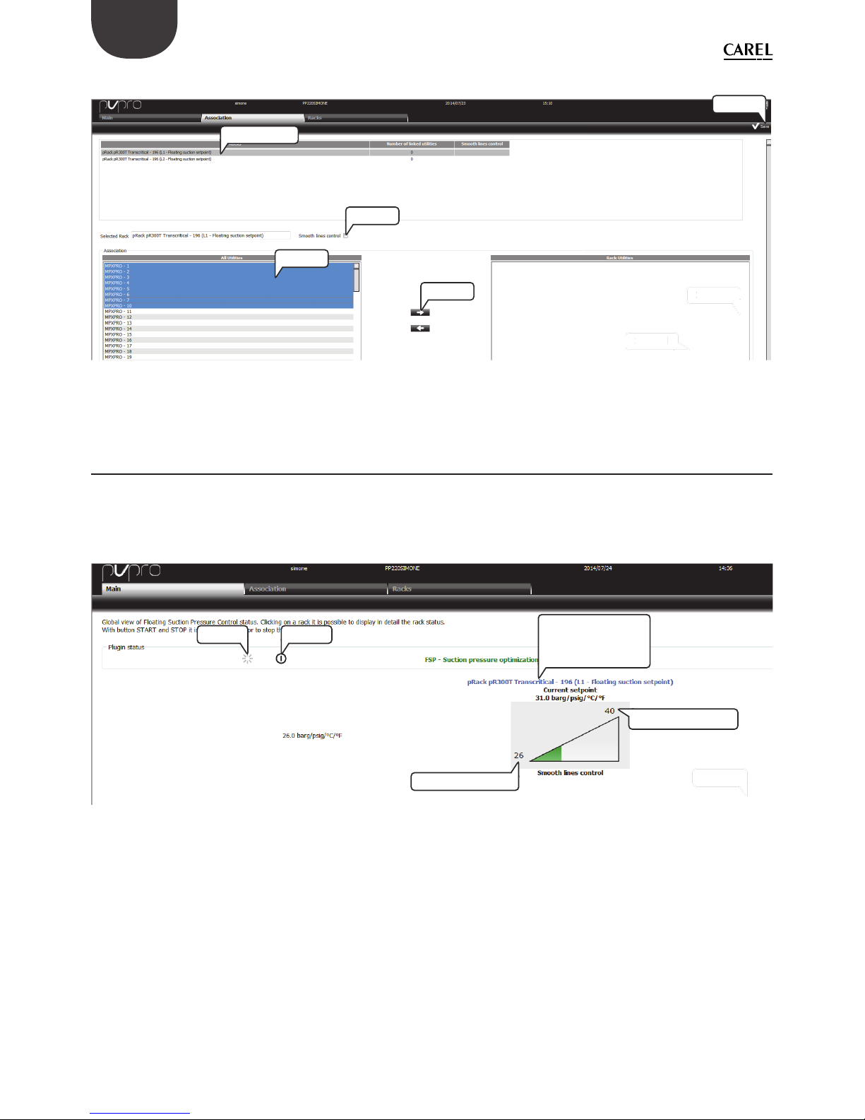
2.2 Rack association
If there is at least one rack selected for the Floating suction function, a number of units can then be associated
with the rack. Each rack can have more than one unit associated ; each unit however can only be associated
with one rack.
In the “Association” tab, proceed as follows
1. double click on a compressor rack, its name will be shown in the “Selected Rack” text box;
2. select the devices from the list on the left;
3. tick the “Smooth line control” checkbox only if all the devices feature this function;
4. click on the RIGHT arrow to associate the units with the rack;
5. click “Save” in the top-right corner.
Page 22
10
+030220575 - 1.1 - 04.12.2014
ENG
The confi guration procedure is illustrated in Figure 2.b.
STEP 2
STEP 1
STE
P 2
STE
P 1
doble click
STEP 2
STEP 3
STEP 4
STEP 5
Fig. 2.b
2.3 Dashboard: main view
The “Dashboard” tab shows all of the compressor racks selected for the Floating suction function. A triangle
represents the status of the set point adaptation, from the minimum to the maximum value.
In this tab, users can enable or disable the plug-in, access the confi guration page and the monitoring page
relating to each rack.
STEP 2
STEP 2
START STOP
Enter conguration
and monitoring
pages
Minimum setpoint
Maximum setpoint
Fig. 2.c
From the “Dashboard”, clicking on the pRack description (blue), users can access the confi guration and
monitoring view of the plug-in.
These two screens are displayed diff erently, depending on whether the associated units feature the Smooth
lines function, i.e., whether or not the association has been created with the Smooth lines fl ag checked (see
paragraph 2.2 for details).
Page 23
11
+030220575 - 1.1 - 04.12.2014
ENG
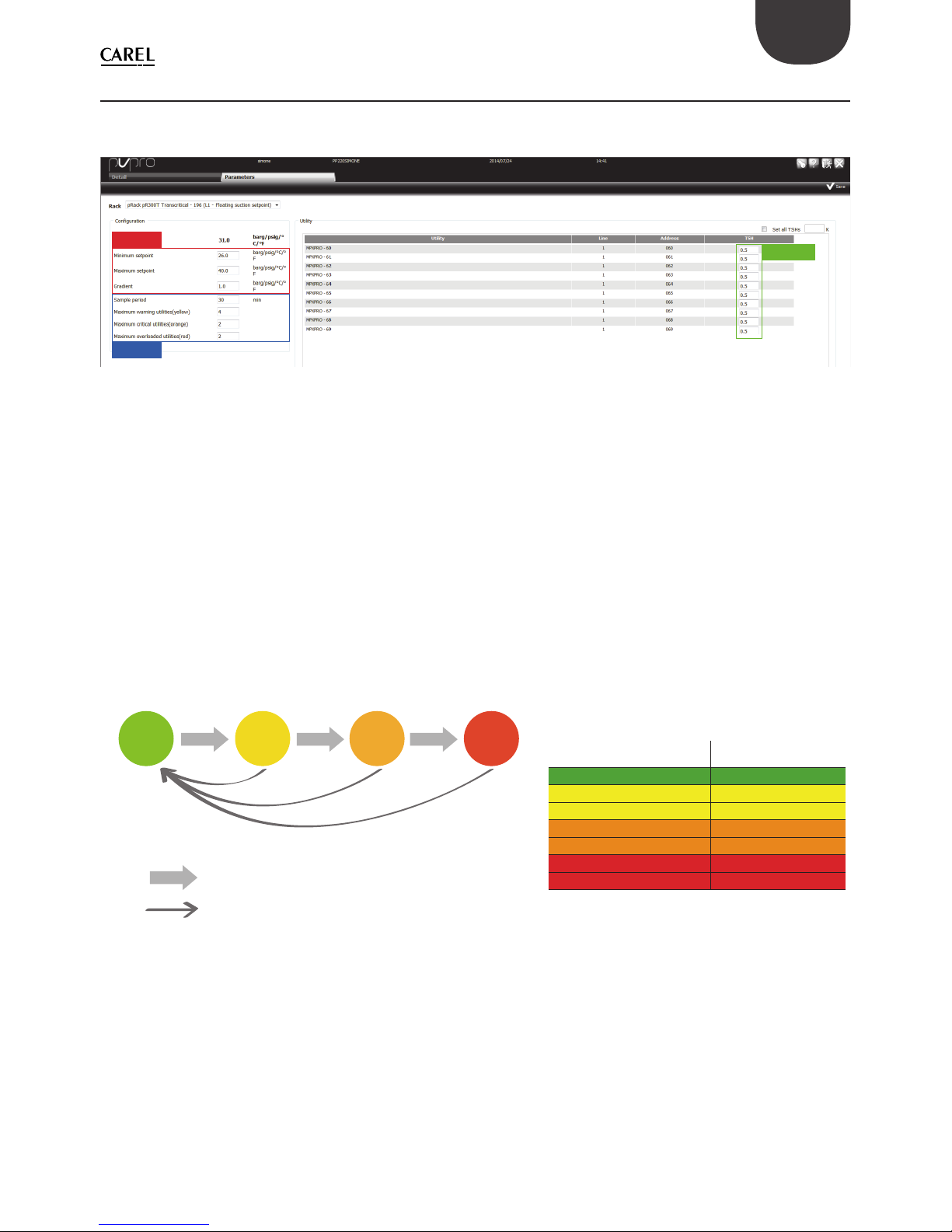
2.4 Dashboard: con guration view and logic (with Smooth lines)
The “Parameters” tab shows the plug-in settings: these can be divided into three groups, with regards to
which devices they relate to: pRack, PVPRO or units.
pRack
PVPRO
Utilities
Fig. 2.d
The pRack confi guration section shows the parameter values set on the pRack (see paragraph 1.3 for details).
The PVPRO settings refer to the plug-in engine parameters. It is possible to specify the sample period, i.e., the
frequency of each potential increase or decrease action on the suction pressure set point, and the rules to
establish whether an action or opposite is to be implemented.
There are three thresholds associated with three colours: yellow, orange and red. The starting colour, green, is
used to indicate units with suitable operation , i.e., control is within a certain margin so as to allow the suction
pressure set point to be increased .
The status (colour) of the units is evaluated every sample period. The rules defi ning status monitoring are
shown in Figure 2.e.
Looking at the number of units with the same colour and at the thresholds relating to each colour, the
criteria for changing the set point are described in the following table:
Utility is working hard: there is no margin
to rise up suction pressure setpoint
Utility is working ne: reset status
Unit condition Action on set point
all green increase
# of yellow < threshold increase
# of yellow ≥ threshold hold
# of orange < threshold increase
# of orange ≥ threshold hold
# of red > 0 hold (*)
# of red ≥ threshold decrease
(*) if the number of red ones is lower than the
red threshold.
Fig. 2.e
Special treatment is reserved for units that are offl ine and for units that do not feature the Smooth lines
function, but have been wrongly associated, with the Smooth lines fl ag checked.
If a unit is unavailable (offl ine for PVPRO) after the sample time, it will be indicated in black and is considered
as being unavailable for pressure set point increases. This unit is considered as if it were yellow, orange or red,
depending on how many times it has been found offl ine.
Page 24
12
+030220575 - 1.1 - 04.12.2014
ENG
If a unit has been wrongly associated as a device featuring the Smooth lines yet does not actually feature
such function , PVPRO will fail to acquire the operating conditions from this device and will indicate it as N/A.
As modifying the suction pressure set point may aff ect control of the line, and PVPRO does not know the
unit’s operating conditions, the plug-in will reset the set point to the minimum value.
These two particular scenarios are illustrated in Figure 2.f.
Y N/A
yellow
orange
O
red
R
if an utility is market as N/A, it means
it doesn’t feature the Smooth line
functionality and any setpoint
increment will be reset.
Fig. 2.f
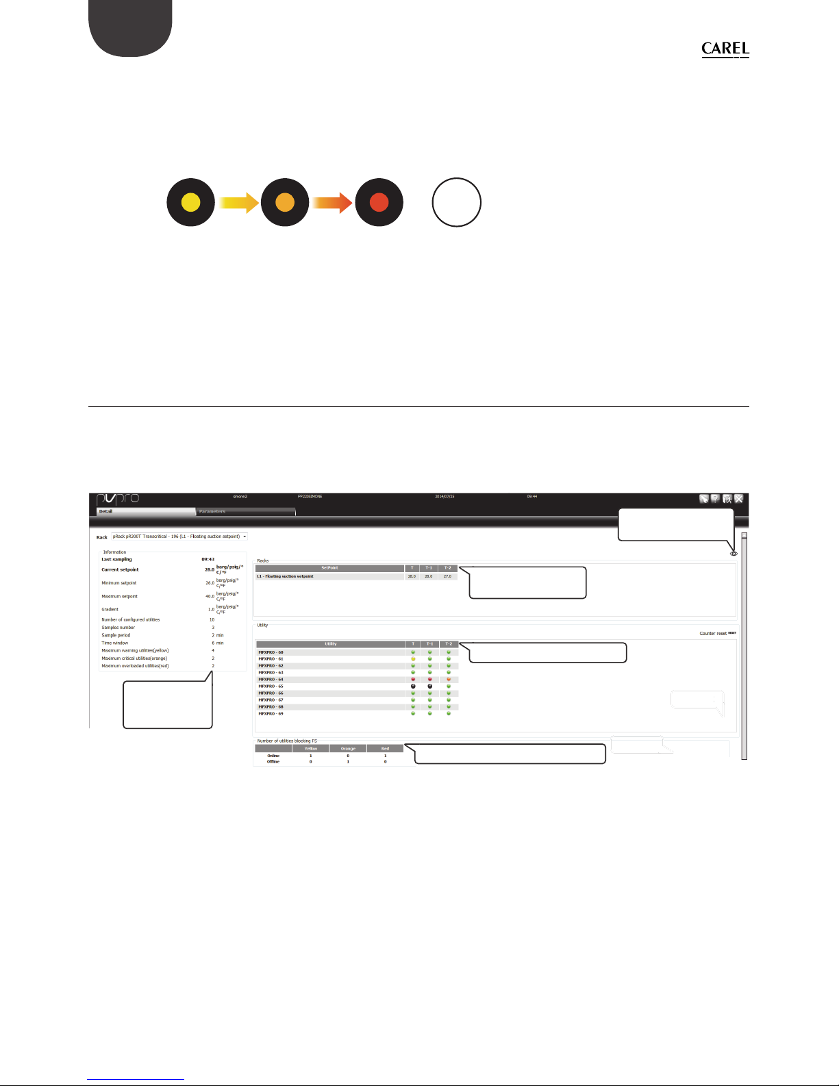
2.5 Dashboard: monitoring view (with Smooth lines)
In the “Details” tab, users can have a detailed overview of unit status. There is a summary of the settings, both
relating to PVPRO and to pRack, and the value of the working set point, with some historical samples.
At the bottom of the page, a table shows the count of units for each colour, divided between online and
offl ine.
STEP 2
S
TEP
2
Summary table
with plug-in
settings
Summary table with colour counting
Main table with utilities status
Current setpoint
and historical values
Click here to enlarge
the historical view
Fig. 2.g
Page 25
13
+030220575 - 1.1 - 04.12.2014
ENG
2.6 Dashboard: con guration view and logic (without Smooth
lines)
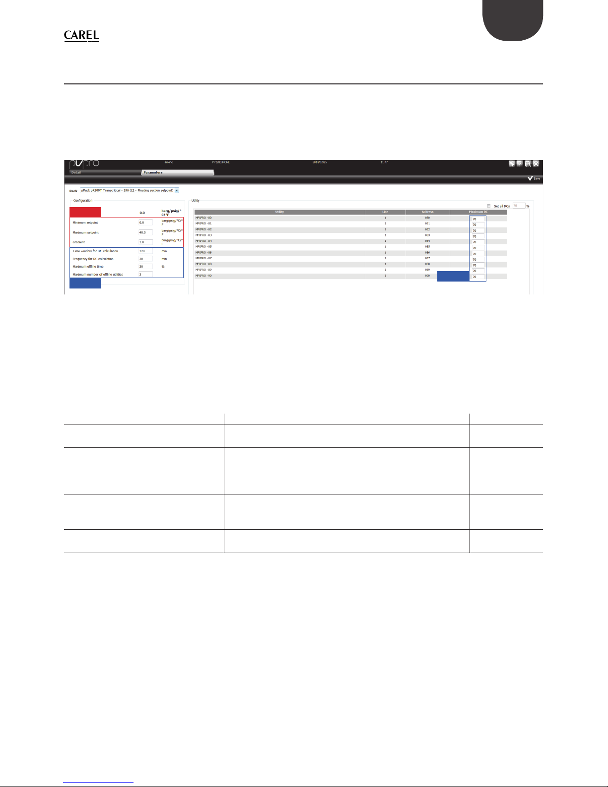
If in a group of units, some or all of these do not feature the Smooth lines function, the Smooth lines fl ag
should not be ticked in the association step (see paragraph 2.2 for details). For this group, the confi guration
page will appear as shown in Figure 2.h.
As the units do not feature any special smooth control function, from PVPRO the user can only confi gure the
parameters relating to the supervisor itself and to the rack.
pRack
PVPRO
PVPRO
Fig. 2.h
In this scenario, the plug-in logic is based on the duty cycle of the units: if the measured percentage is
greater than the confi gured threshold, the line is considered as not having any margin to increase the
suction pressure set point. The threshold is defi ned by entering a percentage for each unit in the “Maximum
DC” column.
The following table shows the meaning of the PVPRO settings and their default values.
Parameter Description Default value
Time window for DC calculation The unit duty cycle of will be calculated within this time
window. The value can range from 10 to 180 minutes.
120 minutes
Frequency for DC calculation Indicates the frequency of the potential action on the set
point: at the end of every period ,the calculated duty cycle
will be considered in order to increase or decrease the set
point. The value can range from 10 to 180 minutes.
30 minutes
Maximum offl ine time Maximum percentage of failed acquisitions for each unit
associated with the rack. If this value is exceeded, the unit is
considered offl ine.
30%
Maximum number of units offl ine If the number of offl ine units exceeds this number, the
suction pressure set point will not be changed.
3
Tab. 2.b
Page 26
14
+030220575 - 1.1 - 04.12.2014
ENG
2.7 Dashboard: monitoring view (without Smooth lines)
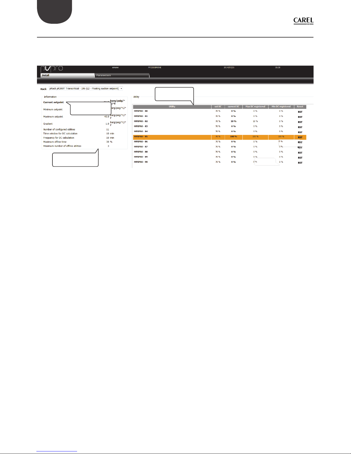
In the “Details” tab, users can have a detailed overview of unit status. There is a summary of the settings, both
relating to PVPRO and to pRack, the current set point and a table showing the current, the maximum and the
minimum duty cycle recorded by PVPRO in the sample time.
STEP 2
STEP 1
STEP 2
S
TEP
1
Summary table with
plug-in settings
Current suction
pressure setpoint
Main table with
utilities status
Fig. 2.i
Page 27

Page 28

CAREL INDUSTRIES HQs
Via dell’Industria, 11 - 35020 Brugine - Padova (Italy)
Tel. (+39) 049.9716611 - Fax (+39) 049.9716600
e-mail: [email protected] - www.carel.com
Agenzia / Agency:
+030220575 - 1.0 - 14.10.2014
 Loading...