

Page 1
powerSplit
Manuale d’uso
User manual
LEGGI E CONSERVA
QUESTE ISTRUZIONI
READ AND SAVE
THESE INSTRUCTIONS
Page 2

Page 3
Vogliamo farvi risparmiare tempo
e denaro!
Vi assicuriamo che la completa lettura
di questo manuale vi garantirà una
corretta installazione ed un sicuro
utilizzo del prodotto descritto.
AVVERTENZE IMPORTANTI
PRIMA DI INSTALLARE O INTERVENIRE
SULL’APPARECCHIO, LEGGERE ATTENTAMENTE E
SEGUIRE LE ISTRUZIONI CONTENUTE IN QUESTO
MANUALE.
Questa apparecchiatura è stata costruita per
funzionare senza rischi per gli scopi prefissati
purché:
• l’installazione, la conduzione e la manutenzione siano
eseguite secondo le istruzioni contenute in questo
manuale;
• le condizioni dell’ambiente e della tensione di
alimentazione rientrino tra quelle specificate.
Ogni utilizzo diverso da questo e l’apporto di
modifiche, non espressamente autorizzate dal
costruttore, sono da intendersi impropri.
La responsabilità di lesioni o danni causati da uso
improprio ricadrà esclusivamente sull’utilizzatore.
Si osservi che questa macchina contiene componenti
elettrici sotto tensione e quindi tutte le operazioni di
servizio o manutenzione devono essere condotte da
personale esperto e qualificato, cosciente delle
necessarie precauzioni.
Prima di accedere alle parti interne sezionare la
macchina dalla rete elettrica.
Smaltimento delle par
ti del controllore
Il controllore è composto da parti in metallo e da par ti in
plastica.Tutte queste parti vanno smaltite secondo le
Normative locali in materia di smaltimento.
Pulizia del controllore
Utilizzare esclusivamente detergenti neutri ed acqua.
We wish to save you time and
money!
We can assure you that a thorough
reading of this manual will guarantee
correct installation and safe use of the
product described.
IMPORTANT
BEFORE INSTALLING OR OPERATING ON THE
DEVICE, CAREFULLY READ THE INSTRUCTIONS IN
THIS MANUAL.
This instrument has been designed to operate without
risks only if:
• installation, operation and maintenance are performed
according to the instructions of this manual;
•environmental conditions and supply voltage fall within
the values indicated here below.
Any different use or changes which have not been
previously authorised by the manufacturer, are
considered improper.
Responsibility for injures or damage caused by
improper use will fall exclusively on the user.
Warning:voltage is present in some electrical
components of this instrument, thus all the service
or maintenance operations must be performed by
expert and skilled personnel only, aware of the
necessary precautions to be taken.
Before accessing the internal parts, disconnect the
power supply.
Disposing of the par
ts of the controller
The controller is made from metal parts and plastic par ts.
All these parts should be disposed of according to local
standards on waste disposal.
Cleaning the contr
oller
Only use neutral detergents and water.
LEGGI E CONSERVA
QUESTE ISTRUZIONI
READ AND SAVE
THESE INSTRUCTIONS
Page 4

Page 5

Indice:
1. INTRODUZIONE: CARATTERISTICHE GENERALI 3
1.1 Modelli disponibili 3
1.2 Caratteristiche 3
2. ARCHITETTURA HARDWARE 4
2.1 Significato degli ingressi ed uscite 4
2.2 Codici degli strumenti ed accessori 6
2.3 Interfaccia utente 8
3. Installazione 10
3.1 Dimensioni e montaggio 10
3.2 Collegamenti elettrici 11
3.3 Impostazione dei principali parametri di configurazione 11
3.4 Configurazione della LAN 11
3.5 Configurazione del sistema e principali funzioni 13
3.6 Funzionalità di rete locale (LAN) 14
3.7 Funzioni HACCP 16
4. Descrizione dei parametri di configurazione 18
4.1 Classificazione dei parametri 18
4.2 / = parametri relativi alla gestione delle sonde di temperatura 19
4.3 A = parametri per la gestione degli allarmi 21
4.4 c = parametri per la gestione del compressore 25
4.5 d = parametri per la gestione dello sbrinamento 28
4.6 F = parametri per la gestione delle ventole dell'evaporatore 31
4.7 H = altre predisposizioni 32
4.8 L = Parametri gestione sensore luce 33
4.9 r = parametri relativi alla regolazione della temperatura 34
4.10 I/S = Parametri LAN 36
4.11 t = Parametri per HACCP, orologio e Defrost temporizzato 36
5. Stati di funzionamento 38
5.1 Stato di ON/OFF del PSB 39
5.2 Esempi d’uso dell’ingresso digitale virtuale. 40
6. Parametri - Tabella Riassuntiva 41
7. ALLARMI e ricerca guasti 45
7.1 Codici di allarme e segnalazioni 45
7.2 Note sugli allarmi 46
7.3 Ricerca ed eliminazione dei problemi 46
8. Caratteristiche tecniche controlli PSB 49
9. Accessori 51
9.1 Chiave copia parametri 51
9.2 Copia e scarico parametri 51
9.3 Segnalazione errori 52
9.4 Caratteristiche tecniche Chiave PSOPZKEY 52
Index:
1. INTRODUCTION:GENERAL CHARACTERISTICS 3
1.1 Models available 3
1.2 Characteristics 3
2. HARDWARE STRUCTURE 4
2.1 Meaning of the inputs and outputs 4
2.2 Instrument and accessory codes 6
2.3 User interface 8
3. Installation 10
3.1 Dimensions and mounting 10
3.2 Electrical connections 11
3.3 Setting the main configuration parameters 11
3.4 LAN configuration 11
3.5 System configuration and main functions 13
3.6 Local network (LAN) functions 14
3.7 HACCP functions 16
4. Description of the configuration parameters 18
4.1 Classification of the parameters 18
4.2 / = temperature probe management parameters 19
4.3 A = Alarm management parameters 21
4.4 c = Compressor management parameters 25
4.5 d = Defrost management parameters 28
4.6 F = Evaporator fan management parameters 31
4.7 H = other settings 32
4.8 L = Light sensor management parameters 33
4.9 r = Temperature control parameters 34
4.10 I/S = LAN parameters 36
4.11 t = HACCP, clock and timed defrost parameters 36
5. Operating modes 38
5.1 PSB ON/OFF mode 39
5.2 Examples on using the virtual digital input. 40
6. Parameters - Summary Table 41
7. ALARMS and troubleshooting 45
7.1 Alarm codes and signals 45
7.2 Notes on the alarms 46
7.3 Troubleshooting 46
8. Technical specifications,PSB controllers 49
9. Accessories 51
9.1 Parameter copy key 51
9.2 Copy and download parameters 51
9.3 Errors signals 52
9.4 Technical specifications, PSOPZKEY key 52
Page 6

Page 7

3
powerSplit manual - cod.+030220320 rel. 1.1 - 09/12/02
1. Introduzione: Caratteristiche generali
1.1 Modelli disponibili
I prodotti PSB sono controlli elettronici integrati per banchi e celle
frigo, anche canalizzati, con gestione dei comandi base:
compressore, defrost, ventilatori ed anche per luce;antiappannamento
e gestione allarmi.
L' interfaccia operatore prevista è con i terminali locali, nelle versioni a
pannello PJ SMALL e LARGE, o con il terminale specifico per celle,
PST MASTER CELLA.
Sono previste le seguenti versioni per la scheda di potenza:
• alimentazione 230Vac
• modelli 4 o 6 relè
• modelli con orologio RTC settimanale
• predisposizione per interfaccia seriale di super visione (RS485)
opzionale, installabile su tutti i modelli
• codice specifico per le celle con terminale remotabile (RS485) fino
a 500 m
1.2 Caratteristiche
•Tre ingressi sonda NTC:regolazione, defrost, prodotto (denominate
anche S1, S2, S3).
• Due ingressi digitali multifunzione ed un ingresso per sensore
presenza luce (apertura porta)
• Realizzazione quadro elettr ico di macchina sulla scheda, con
connessione diretta dei carichi
• Comando per compressore fino a 2 HP e luci fino a 1000 VA max
(16x50 W neon)
• Gestione banchi canalizzati fino a 6 unità con sincronismo defrost
ed attuazioni (mediante LAN).
•Terminale utente collegabile fino a 10 m (500 m in versione per celle)
1. Introduction:General characteristics
1.1 Models available
The PSB products are built-in electronic controllers for showcases and
cold rooms, including multiplexed showcases, with management of the
basic:compressor, defrost, fan functions, as well as light;demist and
alarm management.
The user interface involves local terminals, in the PJ SMALL and
LARGE panel versions, or the specific PST MASTER CELLA terminal
for cold rooms.
The following versions are available for the power board:
• 230Vac power supply
• models with 4 or 6 relays
• models with weekly RTC clock
• ready for the installation of the optional, serial supervisor interface
(RS485), all models
• specific model for cold rooms with remote terminal (RS485),
installable at distances of up to 500m
1.2 Characteristics
• Three NTC probe inputs:control, defrost, product (also called S1,
S2, S3).
• Two multi-function digital inputs and one input for light sensor (door
opening)
• Wiring of the machine’s electrical panel on the board, with direct
connection of the loads
• Control of compressors of up to 2 HP, and lights of up to 1000VA max
(16x50W neon)
• Management of multiplexed showcases of up to 6 units, with
synchronised defrost and actuations (by LAN).
• User terminal with remote installation at up to 10m (500m for the
cold room version)
Page 8
4
powerSplit manual - cod.+030220320 rel. 1.1 - 09/12/02
2. Architettura hardware
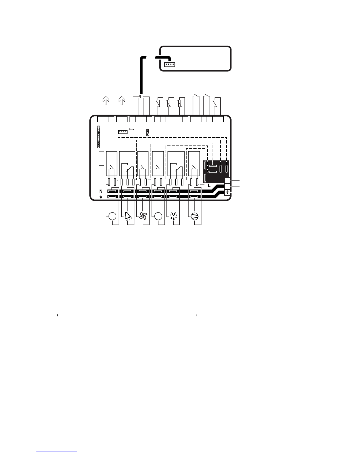
2.1 Significato degli ingressi ed uscite
2.1.1 Alimentazione
• Ingresso alimentazione da rete su tre morsetti a vite, con capacità di
corrente 30 A max
• Tensione di alimentazione a seconda del modello: 230 Vac - 115 Vac
- 24 Vac, 50/60 Hz
• Utilizzo con cavi di sezione da 0,5 a 4 mm
2
(cavo flessibile)
• Morsetti faston di appoggio per connessione carichi:6 morsetti per L,
N e Terra.
Morsetto L:Linea 250 Vac max 30A max
Morsetto N:Neutro 250 Vac max 30A max
Morsetto :Terra 30 A max
Faston L (x6):Linea morsetti faston 16 A max per contatto
Faston N (x6):Neutro morsetti faston 16 A max per contatto
Faston (x6):Terra morsetti faston 16 A max per contatto
2.1.2 Uscite relè
• contatti relè isolati con morsetti faston 6,3 mm capacità di corrente
16 A max
• isolamento principale tra contatti di relè diversi, disconnessione
ridotta sul contatto relè
• utilizzo con contatti faston femmina (6,3 mm) con cavi da 1,5 a 2,5 mm
2
.
• cablaggio connessioni mediante i faston di alimentazione con ponti
(cavo 2,5 mm2con terminazioni faston femmina lunghezza 10-15 cm)
uno per ogni uscita.
2. Hardware structure
2.1 Meaning of the inputs and outputs
2.1.1 Power supply
• Mains power supply connection using three screw terminals, with max
current rating 30A
• Power supply voltage according to the model:230Vac - 115Vac 24Vac, 50/60 Hz
• Cable cross-sections from 0.5 to 4 mm
2
(flexible cables)
• Faston terminals for connecting the loads:6 terminals for L, N and
Earth.
Terminal L: Line 250Vac max 30A max
Terminal N: Neutral 250Vac max 30A max
Terminal : Earth 30A max
Faston L (x6):Line terminals faston 16A max per contact
Faston N (x6):Neutral ter minals faston 16A max per contact
Faston (x6):Earth terminals faston 16A max per contact
2.1.2 Relay outputs
• insulated relay contacts with faston terminals 6.3mm, max.current
rating 16A
• primary insulation main between the contacts of different relays
• connect to female faston contacts (6.3mm), with wires from 1.5 to 2.5
mm
2
.
• wiring connections using the power supply fastons with jumpers
(2.5 mm2wires with female faston terminals, length 10-15cm), one
for each output.
Connessioni interne di alimentazione consigliate
Suggested inside power connections
16A 2HP10A10A16A
RS 485
optional board
Connection to
LAN
Local Area Network
RS485
Connection to
Supervisor
T Products
S3
Power (green)
RX/TX
GND
GND
RX/TX+
RX/TX-
GND (red)
RX/TX (white)
GND (yellow)
T Defrost
S2
T Ambient
S1
Digital Input 1
Digital Input 2
Photo Res.
15 16 17 18 19 20 21 22 23 24 25 26 27 28 29 30 31 32 33 34 35
PROG.
KEY
(12Vdc)
(24Vdc)
L
N
Power Supply
230 Vac (30A max)
10A
PSBoard
-10T50
PST Small/Large
Terminale e/o Visualizzatore
Terminal and/or Display units
PSTCONxxxx
TO I/O
BOARD
1
2
3
Comp.DefrostFanAlarm AUX 2
AUX
AUX 1
Lux
AUX
up-to
10m
1
2
3546
7
8
9
10121113
14
P*
Fig. 2.1.1
Page 9

5
powerSplit manual - cod.+030220320 rel. 1.1 - 09/12/02
Faston 1:C relè compressore 250 Vac 16 A 2 Hp max
Faston 2:NO relè compressore
Faston 3:C relè defrost 250 Vac 16 A res.max
Faston 4:NC relè defrost
Faston 5:NO relè defrost
Faston 8:C relè ventilatori 250 Vac 10 A res.(2 A) max
Faston 9:NO relelè ventilatori
Faston 13:C relè aux1/luce 250 Vac 16 A res.500W-1000VA max
Faston 14:NO relè aux1/luce
Faston 6:C relè aux2/antiapp. 250 Vac 10 A res.(2 A) max
Faston 7:NO relè aux2/antiapp.
Faston 10:C relè allarme 250 Vac 10 A res.(2 A) max
Faston 11:NC relè allarme
Faston 12:NO relè allarme
2.1.3 Ingressi sonde NTC
• ingressi di misura per sonde NTC standard Carel (10 Kohm a 25 ˚C)
• compatibilità con misura PLUG IN, misura da -50 a +90 ˚C
• filtro ingresso 1mS (disturbi veloci, burst), la misura è filtrata SW con
media (/2 da 0,1 a 2s circa)
• connessione con morsetti fissi a vite per filo da 0,5 a 1,5 mm
2
.
• distanza max 30 m per compatibilità normative (surge)
Morsetto 24:ingresso segnale NTC sonda regolazione (ambiente)
(-50/+90˚C )
Morsetto 25:riferimento segnale NTC sonda regolazione
Morsetto 26:ingresso segnale NTC sonda defrost (-50/+90˚C)
Morsetto 27:riferimento segnale NTC sonda defrost
Morsetto 28:ingresso segnale NTC sonda prodotto/defrost 2 (-50/+90˚C)
Morsetto 29:riferimento segnale NTC sonda prodotto/defrost 2
2.1.4 Ingressi digitali
• ingressi da contatto pulito (non alimentato) con corrente di chiusura
8-12 mA
• filtro ingresso 1mS (disturbi veloci, burst), il segnale è filtrato SW
media a 240mS
• connessione con morsetti fissi a vite per filo da 0,5 a 1,5 mm
2
.
• distanza max 30 m per compatibilità normative (surge)
Morsetto 31:ingresso digitale 1
Morsetto 30:riferimento ingresso digitale 1
Morsetto 33:ingresso digitale 2
Morsetto 32:riferimento ingresso digitale 2
Note:
l'utilizzo degli ingressi è programmabile da parametri (ingresso
multifunzione)
2.1.5 Ingresso sensore presenza luce
• ingresso da fotoresistenza per segnalare l'apertura delle porte in
armadi refrigerati, uno o due sensori previsti
• connessione con morsetti fissi a vite (2 vie) per filo da 0,5 a 1,5 mm
2
.
• Distanza massima 30 metri, per compatibilità normative (surge).
Morsetto 34:riferimento (comune) fotoresistenze
Morsetto 35:ingresso fotoresistenze (presenza luce)
Nota:
è disponibile un solo ingresso con la possibilità di collegare uno
o due sensori in parallelo
Faston 1:C compressor relay 250Vac 16A 2 HP max
Faston 2:NO compressor relay
Faston 3:C defrost relay 250Vac 16A res.max
Faston 4:NC defrost relay
Faston 5:NO defrost relay
Faston 8:C fan relay 250Vac 10A res.(2A) max
Faston 9:NO fan relay
Faston 13:C aux1/light relay 250Vac 16A res.500W-1000VA max
Faston 14:NO aux1/light relay
Faston 6:C aux2/demist relay 250Vac 10A res.(2A) max
Faston 7:NO aux2/demist relay
Faston 10:C alarm relay 250Vac 10A res.(2A) max
Faston 11:NC alarm relay
Faston 12:NO alarm relay
2.1.3 NTC probe inputs
• measurement inputs for standard Carel NTC probes (10Kohm at 25 ˚C)
• compatibility with PLUG IN measurements, measuring range from
-50 to +90 ˚C
• 1mS input filter (fast transients, burst)
• connection with fixed screw terminals for wires from 0.5 to 1.5 mm
2
• distance max 30m for standards compliance (surge)
Terminal 24: NTC control probe (ambient) input signal (-50/+90˚C)
Terminal 25: NTC control probe reference signal
Terminal 26: NTC defrost probe input signal (-50/+90˚C)
Terminal 27: NTC defrost probe reference signal
Terminal 28: NTC product/defrost2 probe input signal (-50/+90˚C)
Terminal 29: NTC product/defrost2 probe reference signal
2.1.4 Digital inputs
• inputs from free contacts (not supplied) with closing current of 8-12mA
• 1mS filter input (fast transients, burst)
• connection with fixed screw terminals for wires from 0.5 to 1.5 mm
2
.
• distance max 30m for standards compliance (surge)
Terminal 31: digital input 1
Terminal 30: digital input 1 reference
Terminal 33: digital input 2
Terminal 32: digital input 2 reference
Note:
The use of the inputs can be programmed by setting the corre-
sponding parameters (multi-function inputs)
2.1.5 Light presence sensor input
• input from photocell to signal the opening of the doors on
refrigerated display cabinets, one or two sensors featured
• connection with fixed screw terminals (2-way) for wire cross-sections
from 0.5 to 1.5 mm
2
.
• Maximum distance 30 metres for standards compatibility (surge).
Terminal 34: photocell reference (common)
Terminal 35: photocell input (light presence)
Note:
One input only is available, with the possibility of connecting one
or two sensors in parallel
Page 10

6
powerSplit manual - cod.+030220320 rel. 1.1 - 09/12/02
2.1.6 Connessione terminale
• connessione con alimentazione del terminale PST "Small" o "Large"
PSTxxL
• alimentazione da tensione livellata 20 - 35 Vdc (0,7 W max 50 mA)
protetta da PTC fuse 100 - 140 mA
• velocità seriale prevista 4800 bit/S
• connessione a quattro fili con cavo non schermato AWG28, distanza
max 10 m;per connessione RS485 utilizzare cavi (alimentazione)
con sezione adeguata alla distanza
Morsetto 20:alimentazione terminale +VL (8-35 Vdc)
Morsetto 21:riferimento alimentazione GND
Morsetto 22:segnale Tx/Rx (intf.transistor, livelli TTL)
Morsetto 23:riferimento GND
Per connessione di terminali diversi da PST Large o Small, mediante
interfaccia RS485, le connessioni cambiano come segue:
Morsetto 20:alimentazione terminale +VL (non collegare)
Morsetto 21:riferimento alimentazione GND
Morsetto 22:segnaleTX/RX- RS485
Morsetto 23:segnaleTX/RX+ RS485
Nota:
per i terminali tipo MasterCella l’alimentazione viene fornita
separatamente.
2.1.7 Connessione seriale LAN
• connessione in rete verso altri controlli PJ power MGE (non
supervisione) lung. max 10 m
• velocità seriale prevista 19200 bit/S (default) oppure 9600 bit/S.
Morsetto 18:riferimento alimentazione e segnale GND
Morsetto 19:segnale Tx/Rx (intf.transistor, livelli TTL)
2.1.8 Connettore opzione seriale RS485
Connettore per collegamento scheda opzionale con driver RS485 per
interfacciamento con supervisore
• pin-strip 8 vie con fissaggio scheda mediante asole (saldabile a CS)
per scheda opzione seriale
• velocità seriale prevista 9600-19200 bit/S
• connessione a 3 morsetti a vite fissi (GND, Tx/Rx+, Tx/Rx-)
Morsetto 15:segnale Tx/Rx - (RS485)
Morsetto 16:segnale Tx/Rx + (RS485)
Morsetto 17:riferimento segnale GND
2.1.9 Connettore chiave programmazione
Connessione per chiave di copia parametri con alimentazione diretta
5 Vdc (max 30 mA)
• funzionamento con controllo spento, alimentato da chiave.
• interfaccia seriale di tipo i2c bus con connessione diretta a
microprocessore e memoria interna (non utilizzabile per altre
connessioni)
• connettore a 4 vie standard PLUG IN con segnali:+5V, GND, I2Clk,
I2Dat.
2.2 Codici degli strumenti ed accessori
2.2.1 Controllo PJ Power 4/6 relè 3 sonde NTC
Tabella. 2.2.1
2.1.6 Terminal connection
• connection with power supply for the PST "Small" and PSTxxL
"Large" terminals
• 20 - 35Vdc “clamped”voltage power supply (0.7W max 50mA)
protected by 100 - 140 mA PTC fuse
• serial speed 4800 bit/S
• four-wire connection using non-shielded AWG28 cable, max distance
10m;for the RS485 connection use cables (power supply) with a
suitable cross-section for the distance
Terminal 20: terminal power supply +VL (8-35Vdc)
Terminal 21: power supply GND
Terminal 22:Tx/Rx signal (transistor intf., TTL levels)
Terminal 23: GND
To connect terminals other than the PST Large or Small, using the
RS485 interface, the connections change as follows:
Terminal 20: terminal power supply +VL (do not connect)
Terminal 21: power supply GND
Terminal 22:TX/RX- signal RS485
Terminal 23:TX/RX+ signal RS485
Note:
for the MASTERCELLA terminals, the power supply is connected
separately.
2.1.7 LAN serial connection
• network connection to other PJ power MGE controllers (not
supervisor) max length 10m
• serial speed 19200 bit/S (default) or 9600 bit/S.
Terminal 18: power supply and signal GND
Terminal 19:Tx/Rx signal (transistor intf., TTL levels)
2.1.8 RS485 serial connector option
Optional connector for card with RS485 driver for supervisor interface
• 8-way pin-strip with slotted card for serial option
• serial speed 9600-19200 bit/S
• connection by 3 fixed screw terminals (GND, Tx/Rx+, Tx/Rx-)
Terminal 15:Tx/Rx - signal (RS485)
Terminal 16:Tx/Rx + signal (RS485)
Terminal 17: signal GND
2.1.9 Programming key connector
Connector for the key used to copy the parameters, with direct 5Vdc
power supply (max 30 mA)
• operation when the controller is off, powered by the key
• i2c-bus serial interface with direct connection to the microprocessor
and internal memory (cannot be used for other connections).
• standard 4-way PLUG IN connector with the following signals:+5V,
GND, I2Clk, I2Dat.
Alimentazione Opzioni
CODICI MODELLI 230 115 24 6 Relè 4 Relè RTC RS485 Descrizione
PSB0000000 • • x PS 4 relè 3 NTC senza RTC
PSB0001000 • • • x PS 4 relè 3 NTC con RTC
PSB0000100 • • x PS 6 relè 3 NTC senza RTC
PSB0001100 • • • x PS 6 relè 3 NTC con RTC
A
vvetenza: Il simbolo “x”indica una funzione disponibile se viene installata l'opzione relativa.
Page 11

7
powerSplit manual - cod.+030220320 rel. 1.1 - 09/12/02
2.2.2 Versioni a 4 Relè PSB000000
Questo modello presenta quattro relè per le seguenti funzioni:
COMPRESSORE, DEFROST, FAN, AUX1/LUCE.
Le uscite ALARM e AUX2 non sono abilitate e non sono montati i
relativi componenti (Relè e connessioni).
2.2.3 Versioni con RTC (real-time clock)
Queste versioni offrono un orologio interno per gestire lo sbrinamento
ad orari programmati (6 eventi max.) e la registrazione degli allarmi
HACCP. L'orologio viene utilizzato nel formato dd :hh :mm :ss
(giorno-settimana: ora :minuto :secondo).Il mantenimento dei dati e
avanzamento dell'orologio è garantito da una batteria ricaricabile con
autonomia di circa 6 mesi (da carica completa).
2.2.4 Terminali a pannello
Per l'elenco completo dei codici e le relative funzioni vedere la
documentazione.
2.2.5 Scheda opzione seriale RS485 FCSER00000
Scheda opzionale che permette la connessione del controllo
PowerSplit alla rete di super visione RS485, fino a 199 preiferiche.
Nota:
la connessione avviene mediante un pin-strip 8 vie.
Sulla scheda PSB può essere presente un pin-strip a 10 vie, in questo
caso assicurasi di fare coincidere la posizione della asola presente su
PSB con la chiave di polarizzazione presente sulla scheda FCSER00000.
2.2.6 Chiave di programmazione PSOPZKEY00
Questa chiave hardware opzionale che permette di memorizzare e
duplicare la configurazione dei parametri dei controlli Power-Split.
• Copia dei parametri da controllo verso chiave e viceversa
• Controllo codice, modello e revisione per evitare copie incompatibili
• Segnalazione esecuzione copia con LED bicolore rosso/verde
2.2.7 Contenitore PSOPZBOX00
Contenitore standard da quadro IP55 con passacavi dim.240x190x90
mm completo di piastra per il fissaggio ed accessori (viti, distanziali,
bloccacavi).
2.2 Instrument and accessory codes
2.2.1 PJ Power controller with 4/6 relays, 3 NTC probes
Table 2.2.1
2.2.2 Versions with 4 RELAYS PSB000000
This model has four relays for the following functions:
COMPRESSOR, DEFROST, FAN, AUX1/LIGHT.
The ALARM and AUX2 outputs are not enabled, and the corresponding
components are not fitted (relays and connections).
2.2.3 Versions with RTC (real-time clock)
These versions feature an internal clock to manage the defrosts at set
times (max.6 events) and the saving of the HACCP alarms.
The clock uses the format dd:hh: mm:ss (weekday: hours:minutes:
seconds).The data and the time are stored using a rechargeable
battery, with an autonomy of around 6 months (when completely
charged).
2.2.4 Panel terminals
For the complete list of codes and the corresponding functions, see
the specific document
2.2.5 FCSER00000 RS485 serial card option
Optional board that allows the PowerSplit controller to be connected to
the RS485 supervisor network, up to 199 peripherals.
Note:
the connection is made using an 8-way pin-strip.
The PSB board may have a 10-way pin-strip, and in this case make
sure that the position of the slot on the PSB coincides with the
polarisation key on the FCSER00000 board.
2.2.6 PSOPZKEY00 programming key
This optional hardware key is used to save and copy the
configuration of the parameters for the Power-Split controllers.
• Copies the parameters from the controller to the key and vice-versa
• Checks the code, model and revision to avoid incompatible copies.
• Signals the status using a two-colour LED (red/green.
2.2.7 PSOPZBOX00 container
Standard container for IP55 panels with 240x190x90 mm fairleads,
complete with fastening plate and accessories (screws, spacers, cable
clamps).
Power supply Options
MODEL CODES 230 115 24 6 RELAY 4 RELAY RTC RS485 Description
PSB0000000 • • x PS with 4 relays, 3 NTC without RTC
PSB0001000 • • • x PS with 4 relays, 3 NTC and RTC
PSB0000100 • • x PS with 6 relays, 3 NTC without RTC
PSB0001100 • • • x PS with 6 relays, 3 NTC and RTC
W
arning: The “x”symbol indicates that the function is available if the corresponding option is installed.
Oggetto Codice Funzioni
Visualizzatore SMALL rosso PST00VR100 Ntc , LED 3 digit
Terminale SMALL rosso PST00SR300 Buzzer, Infrared, Ntc, Ingressi digitali, LED 3 digit
Terminale LARGE rosso PST00LR200 Buzzer, Infrared , LED 4 digit
Cavi di collegamento PSTCON0300 3m
PSTCON1000 10m
Flangia di montaggio per PST SMALL PSTFS***** (S1,..S4) Flangia normale o con foratura per tasti e segnalazioni
Flangia di montaggio per PST LARGE PSTFL*****
Object Code Functions
SMALL red display PST00VR100 NTC, 3 digit LED
SMALL red terminal PST00SR300 Buzzer, Infrared, NTC, Digital inputs, 3 digit LED
LARGE red terminal PST00LR200 Buzzer, Infrared, 4 digit LED
Connection cables PSTCON0300 3m
PSTCON1000 10m
Assembly flange for PST SMALL PSTFS***** (S1,..S4) Nor mal flange or with holes for buttons and signals.
Assembly flange for PST LARGE PSTFL*****
Page 12
8
powerSplit manual - cod.+030220320 rel. 1.1 - 09/12/02
2.2.8 Sensore presenza luce PSOPZLHT00
Fotoresistenza incapsulata in terminale plastico trasparente, con cavo
di connessione 3 metri.
2.2.9 Kit programmazione parametri
Permette di leggere e modificare i parametri memorizzati in una chiave
di programmazione (PSOPZKEY00).
2.3 Interfaccia utente
I terminali e visualizzatori previsti sono i modelli "LARGE" e "SMALL"
(codici PSTxx).Sono disponibili anche altri modelli, ad esempio il terminale per celle per i quali si rimanda alla relativa doumentazione.
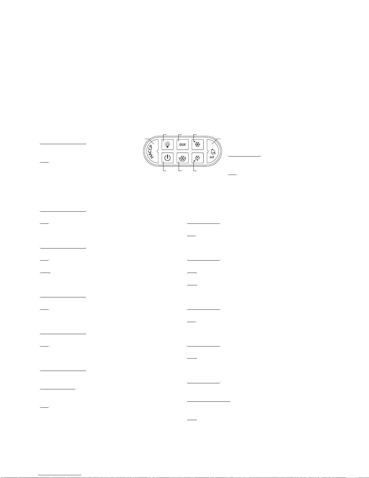
2.3.1 Funzioni Tasti e Led Terminale PJ Large
Tasto “1”(LED rosso)
Funzionamento nor
male
• premuto per 5 sec.resetta allar me HACCP
(HA o HF) se attivo
LED
• acceso fisso - Allarme HACCP per superamento
soglia e tempi (allarme HA)
• Lampeggiante continuo - Allarme HACCP per
superamento soglia e tempi dopo mancanza di
alimentazione (allarme HF)
Tasto “2”(LED giallo)
Funzionamento nor
male
• Premuto per 1 sec.attiva/disattiva uscita relè aux1 (luce)
LED
• Acceso fisso - Uscita relè aux1 (luce) attiva
Tasto “3”(LED verde)
Funzionamento nor
male
• Premuto per 5 sec.ON/OFF unità.
LED
• Acceso fisso - Regolazione in funzione
Nota: la funzione ON/OFF dipende da un param.di abilitazione (se non
abilitato, il controllo è sempre ON), il LED visualizza comunque lo stato.
Tasto “4”(LED giallo)
Funzionamento nor
male
• Premuto per 1 sec.attiva/disattiva uscita relè aux2
LED
• Acceso fisso - Uscita relè aux2 attiva
Tasto “5”(LED verde)
Funzionamento nor
male
• Premuto per 5 sec.attiva il ciclo continuo (dopo la pressione per 5 sec).
LED
• Acceso fisso - Ciclo continuo inserito.
Tasto “6”(LED verde)
Funzionamento normale
• ON/OFF luce dopo 1 sec.di pressione.
• premuto assieme al tasto 7 per 5 sec.attiva il ciclo continuo
Modifica parametri
• Passa da un parametro al successivo.
• Incrementa il valore associato al parametro visualizzato.
LED
• Stabilmente acceso - Compressore in funzione
• Lampeggiante continuo - Richiesta di attivazione compressore
(richiesta freddo)
2.2.8 PSOPZLHT00 light presence sensor
Photocell housed in a transparent plastic terminal, with 3m connection
cable.
2.2.9 Parameter programming kit
Used to read and modify the parameters saved on a programming key
(PSOPZKEY00).
2.3 User interface
The terminals and displays featured are the "LARGE" and "SMALL"
models (codes PSTxx).Other models are available, for example, the
terminal for cold rooms, please refer to the corresponding documents.
2.3.1 Function buttons and LEDs,PJ Large
terminal
Button “1”(red LED)
Nor
mal operation
• pressed for 5 seconds resets the HACCP
alarms (HA or HF) if active
LED
• On steady - HACCP alarm signalling the
exceeding of the threshold and times (HA alarm)
• Continuous flashing - HACCP alarm signalling the
exceeding of the threshold and times after power failure
(HF alarm)
Button “2”(yellow LED)
Nor
mal operation
• Pressed for 1 seconds activates/deactivates the aux1 relay output (light)
LED
• On steady - aux1 relay output (light) active
Button “3”(green LED)
Nor
mal oper
ation
• Pressed for 5 seconds unit ON/OFF.
LED
• On steady - Controller on
Note: the ON/OFF function depends on an enabling param.(if not enabled,
the controller is always ON), the LED in any case displays the status.
Button “4”(yellow LED)
Nor
mal operation
• Pressed for 1 seconds activates/deactivates the aux2 relay output
LED
• On steady - aux2 relay output active
Button “5”(green LED)
Nor
mal operation
• Pressed for 5 sec.starts the continuous cycle (after pressing for 5 sec.).
LED
• On steady - Continuous cycle on.
Button “6”(green LED)
Nor
mal operation
• Light ON/OFF when pressed for 1 sec.
• pressed together with the 7 button for 5 sec.active the continuous cycle
P
arameter modification
• Moves from one parameter to the next.
• Increases the value of the parameter displayed.
LED
• On steady - Compressor on
• Continuous flashing - Request for compressor activation (cooling
request)
1
2 4 6
8
3
5 7
Fig. 2.3.1.1
Page 13

9
powerSplit manual - cod.+030220320 rel. 1.1 - 09/12/02
Tasto “7”(LED giallo)
Funzionamento nor
male
• Premuto per 5 sec attiva uno sbrinamento manuale, se presenti le
condizioni.
Modifca par
ametri
• Passa da un parametro al precedente.
• Diminuisce il valore associato al parametro visualizzato.
LED
• Acceso fisso - Sbrinamento in funzione
• Lampeggiante continuo - sbrinamento pendente.
Tasto “8”(LED rosso)
Funzionamento nor
male
• Tacita allarme acustico, se attivo.
• Premuto per 1 sec.visualizza e/o imposta il set point
• Premuto per più di 5 sec, non in presenza di allarme, dà accesso
al menù dei parametri di tipo F (frequenti)
• Premuto all’accensione del controllo assieme al tasto 7 esegue il
reset dei parametri (ripristino parametri di default)
Modifica par
ametri
• Visualizza il valore del parametro selezionato/esce dalla visualizzazione.
• Premuto per 5 sec esegue la memorizzazione permanente delle
modifiche.
LED
• acceso fisso - allarme attivo.
2.3.2 Elenco funzioni Tasti e Led Terminale PJ Small
Sono presenti solo tre tasti e tre LED degli otto sopra
elencati:6, 7 e 8.
Le funzioni per la modifica parametri sono le stesse già
descritte sopra per il terminale LARGE; per la regolazione
sono previste le funzioni di Ciclo Continuo, Defrost ON-OFF
luce e tacitazione allarmi:
Tasto “6”(LED verde)
Funzionamento nor
male
• ON/OFF luce dopo 1 sec.di pressione.
• Premuto assieme al tasto 7 per 5 secondi attiva il ciclo continuo
LED
• acceso fisso - Compressore in funzione
• Lampeggiante continuo - richiesta di attivazione compressore
(richiesta freddo)
Tasto “7”(LED giallo)
Funzionamento nor
male
• Premuto per 5 sec attiva uno sbrinamento manuale, se presenti le
condizioni.
LED
• acceso fisso - Sbrinamento in funzione
• Lampeggiante continuo - sbrinamento pendente.
Tasto “8”(LED rosso)
Funzionamento nor
male
• Tacita allarme acustico, se previsto.
LED
• acceso fisso - attivo allarme.
Non sono disponibili le seguenti funzioni su tasto:
• HACCP: il reset è possibile solo con accesso ai parametri
• AUX2: il comando dell' uscita non è previsto da tastiera (solo
mediante supervisore)
• ON/OFF: il comando dello stato ON/OFF non è previsto (sempre ON).
Button “7”(yellow LED)
Nor
mal operation
• Pressed for 5 seconds, starts a manual defrost if the conditions are
present.
P
arameter modification
• Moves from one parameter to the previous.
• Decreases the value of the parameter displayed.
LED
• On steady - Defrost on
• Continuous flashing - Defrost progress.
Button “8”(red LED)
Nor
mal operation
• Silences the audible alarm, if active
• Pressed for 1 second displays and/or sets the set point.
• Pressed for more than 5 seconds, and no alarm is active, accesses
the menu the type F parameters (frequent).
• Pressed together with the 7 button when the controller is turned on,
resets the parameters (reset default parameters).
P
arameter modification
• Displays the value of the selected parameter /exits the display.
• Pressed for 5 seconds, saves the modifications.
LED
• On steady - Alarm active.
2.3.2 List of function buttons and LEDs on the PJ Small terminal
There are only three buttons and three LEDs of the eight listed
above:6,7 and 8.
The functions for modifying the parameters are the same as
described above for the LARGE terminal;the controller features
the Continuous cycle, Defrost On-Off functions and the silencing
of the alarms:
Button “6”(green LED)
Nor
mal operation
• Light ON/OFF after pressing for 1 sec.
• Pressed together with the 7 button for 5 sec.start continuous cycle
LED
• On steady - Compressor on
• Continuous flashing - compressor activation request (cooling request)
Button “7”(yellow LED)
Nor
mal operation
• Pressed for 5 seconds, starts a manual defrost, if the conditions are
present.
LED
• On steady - Defrost on
• Continuous flashing - defrost in progress.
Button “8”(red LED)
Nor
mal operation
• Silences the audible alarm, if featured.
LED
• On steady - Alarm active.
The following functions are not available using the buttons:
• HACCP: alarm reset only by accessing the parameters
• AUX2: he output is not controlled from the keypad (only via the
supervisor)
• ON/OFF: the ON/OFF status is not available (always ON).
6
8
7
Fig. 2.3.2
Page 14
10
powerSplit manual - cod.+030220320 rel. 1.1 - 09/12/02
3. Installazione
Installazione e collegamenti
Avvertenze generali - ambienti di destinazione e collegamenti
Le seguenti condizioni soddisfano una corretta installazione:
1. evitare il montaggio dello strumento negli ambienti che presentano:
ampie e rapide fluttuazioni della temperatura ambiente, umidità
relativa maggiore dell’80%, esposizione a getti d’acqua diretti
sotto pressione, alte interferenze elettromagnetiche e/o
radiofrequenze (per es.di antenne trasmittenti);
2. utilizzare capicorda adatti ai morsetti in uso.Allentare ciascuna vite
ed inserirvi i capicorda, quindi serrare le viti. Ad operazione ultimata
tirare leggermente i cavi per verificarne il corretto serraggio;
3. separare quanto più possibile i cavi delle sonde e degli ingressi digitali
dai cavi dei carichi induttivi e di potenza per evitare possibili disturbi
elettromagnetici.Non inserire mai nelle stesse canaline (comprese
quelle dei cavi elettrici) cavi di potenza e cavi delle sonde.Evitare
che i cavi delle sonde siano installati nelle immediate vicinanze di
dispositivi di potenza (contattori, interruttori magnetotermici o simili);
4. ridurre il più possibile il percorso dei cavi dei sensori ed evitare che
compiano percorsi a spirale che racchiudano dispositivi di potenza.
Per prolungare i cavi delle sonde, usare cavi con sezione minima di
almeno 0,5 mm
2
;
Precauzioni di installazione:
• i cavi di collegamento devono garantire l'isolamento almeno fino a 90 ˚C
• per il montaggio scheda utilizzare solo distanziali plastici e prevedere
almeno 10 mm rispetto a parti conduttive vicine alle connessioni
della scheda
• i collegamenti sonde e ingressi digitali devono risultare inferiori a 30
m di sistanza, adottare le adeguate misure di separazione dei cavi
per il rispetto delle normative di immunità
• bloccare adeguatamente i cavi di connessione delle uscite per evitare
contatti con componenti in bassissima tensione.
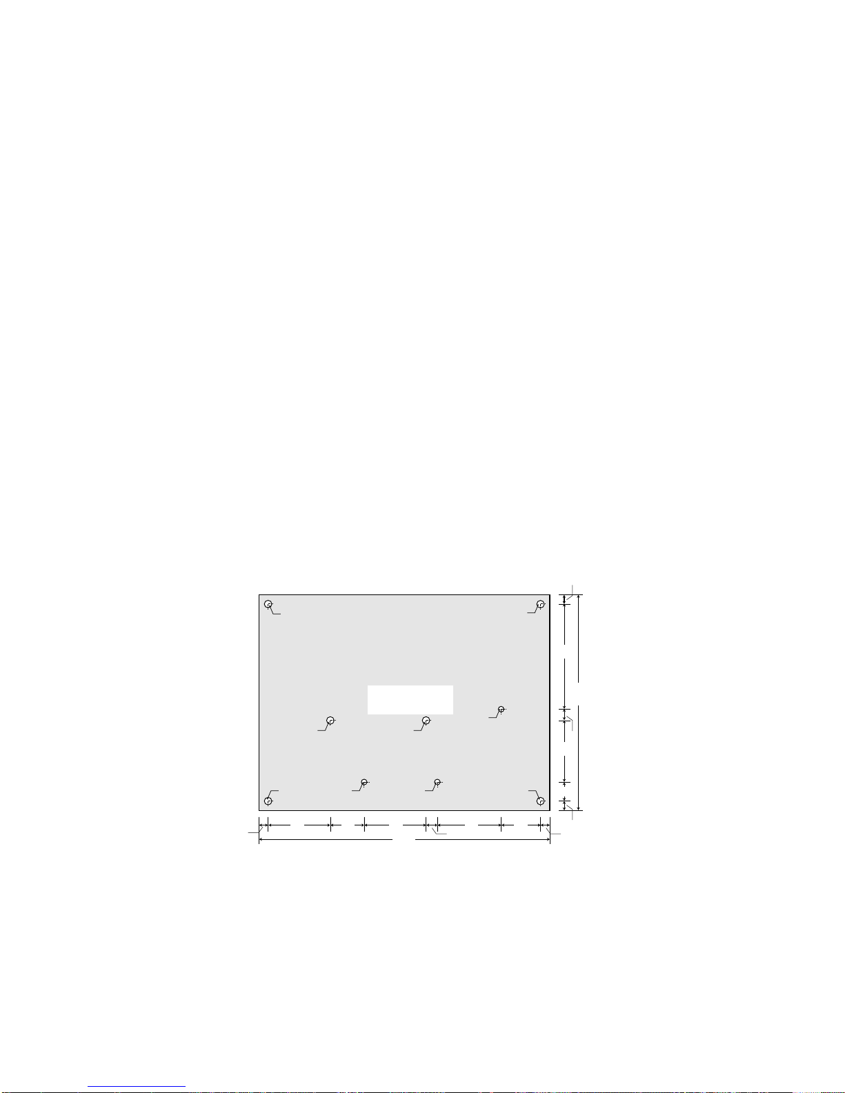
3.1 Dimensioni e montaggio
Il montaggio del PSB è a
retroquadro mediante distanziali
plastici di aggancio della scheda;
è possibile utilizzare anche
torrette metalliche, ma in tal caso
si devono verificare le distanze
di isolamento per la conformità
alle normative di sicurezza.
Nota:
Fori (A) diam. 4 mm per fissaggio
scheda mediante distanziali plastici.
Punti (B) di appoggio per
sostegno scheda inserimento connessioni FASTON.
Distanziali e particolari di
appoggio scheda forniti da Carel
assieme al controllo.
3. Installation
Installation and connections
General warnings – installation and connection environments
The following conditions represent the correct installation:
1. avoid installing the instrument in environments featuring: wide and
rapid fluctuations in ambient temperature, relative humidity over
80%, exposure to direct jets of pressurised water, high levels
of electromagnetic and/or radio-frequency interference
(e.g.transmitting antennae);
2. use cable terminals that are suitable for the terminals being used.
Loosen each screw and insert the cable ends, then tighten the
screws.Once this operation has been completed, lightly tug the
cables to check that they are sufficiently tight;
3. separate as much as possible the probe and digital input cables
from cables carrying inductive loads and power cables, to avoid any
electromagnetic disturbance.Never lay power cables and
probe cables in the same channels (including those for the electrical
cables).Do not install the probe cables in the immediate vicinity of
power devices (contactors, thermal overload switches or the like);
4. reduce the path of the sensor cables as much as possible and avoid
laying spiral paths around power devices.To extend the probe
cables, use cables with a minimum cross-section of at least 0.5 mm
2
;
Precautions for installation:
• the connection cables must guarantee insulation to at least 90˚C
• when mounting the board, only use plastic spacers and leave a
distance of at least 10mm from the conducting parts near the board
connections
• the probe and digital input connections must be located at a distance
of less than 30m, adopt adequate measures for separating the
cables, so as to ensure compliance with the immunity standards
• suitably clamp the output connection cables so as to avoid contact
with low voltage components.
3.1 Dimensions and mounting
The PSB is mounted at the rear
of the panel, using plastic
spacers for fastening the board;
metal turrets can also be used,
but in this case the insulation
distance must be checked for
compliance with the safety
standards.
Notes:
(A) 4 mm diam.holes for
fastening the board using
plastic spacers.
(B) Board supports for the
FASTON connections.
Spacers and board supports
supplied by Carel together with
the controller.
scheda PSB000**00
PSB000**00 board
155
33 18 33 33 22
115
33 56
10
5
56
5
6
5
A
A A
A
B B
B
A A
Fig. 3.1.1
Page 15

11
powerSplit manual - cod.+030220320 rel. 1.1 - 09/12/02
3.2 Collegamenti elettrici
Fare riferimento allo schema elettrico di collegamento (vedi Fig.2.1.1)
• Alimentazione L, N, T:utilizzare cavi con sezione adeguata al carico
da 2,5 a 4 mm
2
• Connessione carichi: terminazione con contatti faston femmina
6,3 mm con cavi di sezione 1,5- 2,5 mm
2
• Ponticelli interni per alimentazione carichi come punto precedente
• Connessione sonde e ingressi digitali con cavi da 0,5 a 1,5 mm
2
• Connessione terminale con cavo previsto PSTCABxx
• Conness.ser. LAN con cavo bipolare 0,5 mm2non è richiesto schermo
• Connessione ser iale per super visore utilizzare doppino twistato con
schermo in come richiesto da sistema di supervis.
• Connessione per terminale RS485 utilizzare doppino twistato con
schermo
3.3 Impostazione dei principali parametri di configurazione
3.3.1 Parametri di rilievo per tutte le unità (Master/Slave)
In base alla programmazione di default si ha AL = 0 e AH = 0 (allarmi
non abilitati) e l'eventuale segnalazione di allarme è ritardata di 120
minuti (Ad=120).Con uno o entrambi gli allar mi abilitatati (valore > 0,
es:4) il valore associato ad Ad indica i minuti di ritardo che il controllo
deve attendere prima di generare un allarme di temperatura.
Ovviamente se durante il ritardo programmato le condizioni di
temperatura ritornano regolari (ovvero entro i ±4 gradi attorno al punto
di lavoro impostato) non si genererà alcun allarme, e si resetterà il
conteggio dei minuti.
NO
TA: durante l'installazione può succedere che, entro i 120 minuti di
ritardo previsti, l'unità non si porti nell'intervallo attorno al Set-Point
impostato, per cui si attiva l'allarme di temperatura.In tale caso si
suggerisce di aumentare il ritardo, modificando il parametro Ad.
3.3.2 Parametri relativi allo sbrinamento
Se lo strumento è utilizzato per la gestione dello sbrinamento è
necessario controllare alcuni parametri prima di procedere con
l'avviamento, in particolare:
• dI: Intervallo tra gli sbrinamenti (senza RTC o senza orari programmati)
• dP: Durata massima sbrinamento
• d0: Tipo di sbrinamento
• dt: SET POINT temperatura di fine sbrinamento.
3.4 Configurazione della LAN
Collegando più PSB tra loro è possibile realizzare una LAN, rete
locale, costituita da un PSB Master che sincronizza il funzionamento
di altri controlli PSB Slave per banchi canalizzati modulari.
I parametri principali di configurazione della LAN sono:
P
er il Master:
• il parametro “In”deve essere posto a 1.
• parametro “Sn”(Slave number): da 1 a 5, numero di Slave sulla LAN;
all’accensione compare a display “uM”:unità Master.
• parametri di impostazione orari sbrinamento:”¯Tx“-Tx”, “_Tx”;x = 1,
2,..., 6:ore e minuti relativi all’orario del defrost (solo se RTC
presente) risoluzione 1 min.
• parametri “tM”, “th”, “td”:ora, minuto, giorno della settimana (solo se
RTC presente)
P
er gli Slave:
• parametro “H0”(Slave address): indirizzo dello slave sulla LAN;
all’accensione della macchina, se configurata quale Slave, viene
visualizzato uSx (x=1..5).
3.2 Electrical connections
Refer to the wiring diagram (see Fig.2.1.1)
• Power supply L, N, E:use cables with a suitable cross-section for the
load, from 2.5 to 4 mm
2
• Load connections:6.3mm female fastons with wire cross-section
of 1.5- 2.5 mm
2
• Internal jumpers for power supply loads, as for the previous point.
• Probe and digital input connections, with wires from 0.5 to 1.5 mm
2
• Terminal connections using the PSTCABxx cable
• LAN serial connection with 0.5 mm2two-wire cable, no shield required
• supervisor serial connection, use twisted pair plus shield, as required
by the super visor y system
• RS485 terminal connection, u use twisted pair plus shield
3.3 Setting the main configuration parameters
3.3.1 Parameters valid for all units (Master/Slave)
Based on the default settings, AL = 0 and AH = 0 (alarms not enabled)
and any alarm signal is delayed by 120 minutes (Ad=120). When one
or both the alarms are enabled (value > 0, e.g.:4 ), the value of Ad
indicates the delay in minutes that the controller waits before signalling
a temperature alarm.Obviously, if during the set delay the temperature
conditions return within the limits (that is, within the ±4 degrees around
the set point), no alarm will be generated, and the count will restart.
NO
TE: during installation the unit might not reach the interval around
the set point within the 120 minute delay time, and therefore the
temperature alarm will be activated.In this case it is recommended to
increase the delay by modifying the parameter Ad.
3.3.2 Defrost parameters
If the instrument is used for defrost management, a number of
parameters need to be checked before commissioning, in particular :
• dI:Interval between defrosts (without RTC or without set times)
• dP:Maximum defrost duration
• d0:Type of defrost
• dt:end defrost temperature SET POINT.
3.4 LAN configuration
The PSB units can be connected together to form a LAN (local
network) made up of a PSB Master that synchronises the operation of
the other PSB Slaves for modular multiplexed showcases.
The main LAN configuration parameters are:
F
or the Master:
• the parameter “In”must be set to 1.
• parameter “Sn”(number of Slaves):from 1 to 5, the number of Slaves
in the LAN;when turned on the display shows “uM”:Master unit.
• parameters for setting the defrost times :”¯Tx“-Tx”, “_Tx”;x = 1, 2,...,
6:hours and minutes corresponding to the defrost time (only if the
RTC is fitted), resolution 1 minute.
• parameters “tM”, “th”, “td”:hours, minutes, day of the week (only if the
RTC is fitted)
F
or the Slaves:
• parameter “H0”(Slave address):address of the slave in the LAN;
when the machine is switched on, if configured as a Slave, uSx is
displayed (x=1..5).
Page 16

12
powerSplit manual - cod.+030220320 rel. 1.1 - 09/12/02
3.4.2 Tabella riassuntiva dei parametri da verificare durante
l’installazione
3.4.2 Summary of the parameters to be checked during
installation
Codice Parametro Tipo Min Max U.M. Def
PARAMETRI LAN
Sn Numero di slave (per il Master) C 0 5 - 1
In Configurazione Master/Slave C 0 1 0
H0 indirizzo su seriale (per gli Slave) C 1 199 - 1
PARAMETRI REGOLATORE
rd Differenziale regolatore F 0.1 +19.9 °C/°F 2
PARAMETRI SBRINAMENTO
d0 Tipo di sbrinamento (0=resistenza, 1=gas caldo) C 0 3 flag 0
dI Intervallo tra gli sbrinamenti F 0 199 ore 8
dt Set point temperatura di fine sbrinamento F -40 +199 °C/°F 4
PARAMETRI DI ALLARME
Ad Ritardo allarme di temperatura C 0 +199 min 120
PARAMETRI VENTOLE
F4 relè fan usato per le ventole o come ausiliario C 0 2 - 0
ALTRE PREDISPOSIZIONI
H1 configurazione relè ausiliario n.1 C 0 7 - 0
H2 configurazione relè ausiliario n.2 (nelle unità a 6 relè) C 0 7 - 0
Funzione HACCP
tr Tempo ritardo allarme HACCP ed abilitazione allarme C 0 199 min 0
ORARI DI SBRINAMENTO (solo per i Master con RTC)
¯t1 giorno del pr imo evento di defrost C 0 10 0
-t1 ora del x orario di defrost settabile C 0 24 ore 0
_t1 minuto del primo orario di defrost settabile C 0 59 min 0
...
¯t6 giorno del pr imo evento di defrost C 0 10 0
-t6 ora del x orario di defrost settabile C 0 24 ore 0
_t6 minuto del primo orario di defrost settabile C 0 59 min 0
Code Parameter Type Min Max UOM Def
LAN PARAMETERS
Sn Number of slaves (for the Master) C 0 5 - 1
In Master/Slave configuration C 0 1 0
H0 Serial address (for the Slaves) C 1 199 - 1
CONTROLLER PARAMETERS
rd Control differential F 0.1 +19.9 °C/°F 2
DEFROST PARAMETERS
d0 Type of defrost (0=electric heater, 1=hot gas) C 0 3 flag 0
dI Interval between defrosts F 0 199 hours 8
dt End defrost temperature set point F -40 +199 °C/°F 4
ALARM PARAMETERS
Ad Temperature alarm delay C 0 +199 mins 120
FAN PARAMETERS
F4 fan relay used for the fans or as an auxiliary C 0 2 - 0
OTHER SETTINGS
H1 configuration of auxiliary relay no.1 C 0 7 - 0
H2 configuration of auxiliary relay no.2 (in the units with 6 relays) C 0 7 - 0
HACCP functions
tr HACCP alarm delay time and enable alarm C 0 199 mins 0
DEFROST TIMES (only for the Master with RTC)
-t1 day of the first defrost event C 0 10 0
-t1 hours of the xth settable defrost time C 0 24 hours 0
_t1 minutes of the first settable defrost time C 0 59 mins 0
...
-t6 day of the first defrost event C 0 10 0
-t6 hours of the xth settable defrost time C 0 24 hours 0
_t6 minutes of the first settable defrost time C 0 59 mins 0
Page 17

13
powerSplit manual - cod.+030220320 rel. 1.1 - 09/12/02
Sistemi Master - Slave in unità canalizzate: principali parametri da
verificare:
Note:
1- In = 1 su Master e In = 0 su tutti gli Slave
2- H0 = 0 su Master e da 1 a 5 in sequenza partendo da 1 su
Slave
3- LL = 0 su Master e = 1 su Slave per abilitare ON/OFF
sincronizzato
4- Lo = 0 su Slave , configurabile su Master
5- d2 = 1 su Master e su Slave
3.5 Configurazione del sistema e principali funzioni
3.5.1 Collegamento di terminali e visualizzatori
È possibile collegare ad un controllo PSB un terminale ed un
visualizzatore anche con alimentazione presente, predisponendo una
connessione sconnettibile.
Questo è particolarmente utile a scopo diagnostico in sistemi
Master/Slave, nei quali ad es.sia presente solo il terminale del Master,
e ci sia la necessità di vedere gli eventuali errori presente negli Slave.
Bisogna tener conto delle seguenti particolarità:
1. se il visualizzatore per qualche motivo si dovesse bloccare, non sarà
resettato dal Power Split, ma sarà compito dell’utente.
2. Con il terminale configurato come non abilitato (/t=0), il sistema
continuerà in ogni caso ad interrogarlo e visualizzerà 3 trattini “- - -“.
3. Se il terminale è configurato attivo (/t≠0), il sistema controllerà le
eventuali condizioni anomale del sistema e genererà, se necessario,
il segnale di reset.
Questo significa che se il terminale viene sconnesso, in questa
configurazione, e il visualizzatore sia configurato attivo (/7≠0), si
vedrà il visualizzatore resettarsi ciclicamente.
4. Se il sistema prevede il solo visualizzatore, è necessario impostare
/t=0 per prevenire il reset ciclico del visualizzatore.
5. Se non è presente il visualizzatore, questo deve essere
TASSATIVAMENTE disabilitato (/7≠0), perché il Power Split attende
un timeout di 2 sec.sulla risposta del visualizzatore, con
conseguente rallentamento della comunicazione.
Si ricorda inoltre che:
• se il ter minale perde la comunicazione con il PSB indicherà “Cn”.
•se, invece, il terminale non ha mai comunicato con il PSB, potrà
indicare E0 se manca la sonda di temperatura del terminale,
o visualizzerà la temperatura misurata dalla sonda del terminale,
se connessa.
Master - Slave systems for multiplexed units: main parameters to
be checked:
Note:
1- In = 1 on the Master and In = 0 on all the Slaves
2- H0 = 0 on the Master and from 1 to 5 in sequence, starting
from 1, on the Slaves
3- LL = 0 on the Master and = 1 on the Slaves, to enable
synchronised ON/OFF
4- Lo = 0 on the Slave, can be configured on the Master.
5- d2 = 1 on the Master and on the Slaves.
3.5 System configuration and main functions
3.5.1 Connecting the terminals and displays
A PSB controller can be connected to a terminal and a display even
when power is supplied, by fitting a removable connection.
This is especially useful for diagnostic purposes in Master/Slave
systems, in that only the Master terminal is present, and there is the
thus the need to see any errors that me be present on the Slaves.
The following points should be considered:
1. if the display is blocked for some reason, it will not be reset by Power
Split, but rather must be reset by the user.
2. When the terminal is configured as disabled (/t=0), the system will in
any case continue to interrogate it, and will show 3 dashes “- - -“.
3. If the terminal is enabled (/tπ0), the system will check any abnormal
conditions in the system, and will if necessary, generate the reset
signal.
This means that if the terminal is disconnected, with this
configuration and with the display enabled (/7π0), the display will be
reset cyclically.
4. If the system features the display only, /t must be set to 0, to prevent
the cyclical reset of the display.
5.If the display is not present, this MUST be disabled (/7≠0), as Power
Split features a 2 second time-out for the response from the display,
and consequently communication becomes slower.
It should also be remembered that:
• if the ter minal loses communication with the PSB, it will indicate “Cn”.
•if, on the other hand, it has never received communication from the
PSB, it will indicate E0 if the terminal temperature probe is missing,
or the temperature measured by the terminal probe, if connected.
Codice Parametro Tipo Min Max U.M. Def
PARAMETRI LAN
Sn Numero di slave (per il Master) C 0 5 - 1
In Configurazione Master/Slave (Nota 1) C 0 1 flag 0
H0 Indirizzo seriale (per gli Slave) (Nota 2) C 1 5 - 1
LL abilitazione on/off da rete (Nota 3) C 0 1 flag 0
Lo abilitazione tasto on/off (Nota 4) C 0 1 flag 0
d2 tipo di comando defrost da rete (Nota 5) C 0 1 flag 0
Code Parameter Type Min Max UOM Def
LAN PARAMETERS
Sn Number of slaves (for the Master) C 0 5 - 1
In Master/Slave configuration (Note 1) C 0 1 flag 0
H0 Serial address (for the Slaves) (Note 2) C 1 5 - 1
LL enable network on/off (Note 3) C 0 1 flag 0
Lo enable on/off button (Note 4) C 0 1 flag 0
d2 type of network defrost (Note 5) C 0 1 flag 0
Page 18

14
powerSplit manual - cod.+030220320 rel. 1.1 - 09/12/02
3.5.2 Riconfigurazione di un controllo con i parametri di fabbrica
(default)
In situazioni di funzionam.molto particolari (forti disturbi impulsivi di origine elettromagnetica) può accadere che lo strumento rilevi errori nella
memorizzazione interna dei dati, compromettendone il corretto funzionamento.Nel caso il microprocessore individui un errore nella memorizzazione dei dati, viene visualizzata sul display la seguente sigla:
EA
Per ripristinare il corretto funzionamento è necessario seguire una
procedura particolare detta di RESET.
Questa procedura è assolutamente eccezionale
, come lo sono le cause
che la possono richiedere, ma è quasi sempre possibile ripristinare il
corretto funzionamento.È comunque buona regola indagare sulle cause
che hanno generato questo tipo di errore in modo da evitarne il
ripetersi. In particolare si invita a leggere con attenzione il capitolo
“Installazione” ed il paragrafo “Avvertenze”del presente manuale.
Quando l'errore EA si presenta con frequenza si suggerisce comunque
di far verificare il controllo in quanto potrebbe non essere garantita la precisione originaria.
Per resettare il controllo, procedere nel seguente modo:
• togliere tensione allo strumento
• premendo contemporaneamente i tasti e , ridare tensione
• a display l’indicazione “– 3”, a questo punto rilasciare i tasti
ricaricata la configurazione di fabbrica, lo strumento esegue
automaticamente un riavvio
Nota importante: la procedura di RESET ripristina lo strumento
assegnando ai parametri il valore previsto in fabbrica (detto valore di
Default), perdendo, quindi, tutte le modifiche eventualmente apportate
ai parametri di lavoro.
Vista la delicatezza della manovra, la procedura di reset deve essere
eseguita da personale specializzato.Tale procedura comunque non
danneggia lo strumento bensì lo riporta alla configurazione con cui è
stato prodotto.Se, quindi, si sono modificati i parametri di funzionamento
in modo disordinato, al punto da perdere il controllo del regolatore, si
può resettare il controllo per riportarsi alla configurazione iniziale.
Alcune eventuali personalizzazioni vengono cancellate, H1, H2, A4,
A5, ecc., e vanno quindi ripristinate.
Se sono state perse anche personalizzazioni applicate ai livelli di
visibilità (C o F), per ripristinarle è necessario usare una chiave di
copia opportunamente programmata.
3.6 Funzionalità di rete locale (LAN)
3.6.1 Il defrost di rete (d2 = 1 su tutte le unità)
Il Master, ogni volta che esegue uno sbrinamento, propaga il comando
di sbrinamento a tutta l’isola canalizzata (banco controllato dal Master
+ banchi controllati dagli Slave) ed attende che tutte le unità siano
uscite dal defrost prima di comandare la fine del defrost su tutta la rete.
Gli Slave usciti dal defrost, attendono a loro volta il comando di fine
defrost del Master prima di passare in post-gocciolamento (durante
questa fase il LED lampeggia).
Ricevuto il comando di fine defrost gli Slave si portano in
post-gocciolamento.
Il defrost di ogni singola unità e quello su rete terminano comunque per
time-out.
Il time-out assoluto di fine defrost in unità canalizzate è par
i a dP a cui
v
anno sommati 5 minuti, questo tempo inizia a essere calcolato a
partire dall’inizio del defrost nell’unità Master.
Quindi, se il Master è configurato per il defrost a tempo, il time-out
massimo è pari dP + 5 min.
Se non esistono le condizioni, il Master non può andare in defrost, di
conseguenza non propagherà il defrost sino a quando esso stesso non
potrà eseguirlo.
In sintesi, gli Slave andranno in defrost comandato da rete solo quando
il Master andrà in defrost.
3.5.2 Reconfiguring a controller with the default parameters
In specific operating situations (strong electromagnetic disturbance),
the instrument may show errors when saving the data. These errors
may compromise the correct operation of the instrument.If the
microprocessor identifies an error in the saving of the data, the
display shows the following code:
EA
To restore correct operation, a RESET procedure needs to be
performed.
This procedure must only be performed in exceptional circumstances,
as the possible causes are also exceptional, however it is almost
always possible to restore correct operation.
It is in any case good practice to seek the cause of this type of error,
so as to prevent it from being repeated.In particular, carefully read the
chapter on “Installation”and the paragraph “Warnings”of this manual.
If the error EA occurs frequently, the controller should be checked, as
the specified precision may not be guaranteed.
To reset the controller, proceed as follows:
• switch the instrument off
• press the and buttons at the same time, then connect power
again
• the display will show “– 3”, at this point release the buttons
once the default configuration has been loaded, the instrument is
automatically rebooted
Important note: the RESET procedure resets the instrument by setting
the parameters to the default values.Any modifications made to the
operating parameters will thus be lost.
Given the delicacy of this operation, the procedure must be performed
by specialist personnel.This procedure does not damage the
instrument, but rather resets its original configuration when purchased.
Therefore, if the operating parameters have been modified in a
disorganised fashion, to the point where the controller is unworkable,
it can be reset to its original configuration.
Some custom settings are deleted, e.g.H1, H2, A4, A5, etc., and
should thus be reset.
If any custom settings involving the levels of visibility (C or F) have
been lost, to reset them use a suitably programmed hardware key.
3.6 Local network (LAN) functions
3.6.1 Network defrost (d = 2 1 on all units)
The Master, whenever performing a defrost, propagates the defrost
control to the entire multiplexed island (showcase controlled by the
Master + showcases controlled by the Slave) and waits for all the units
to end defrosting before sending the end network defrost command.
When the Slaves finish defrosting, they await the end defrost
command from the Master before starting the post-dripping phase; the
LED flashes during this phase.
Once the end defrost command has been received, the Slaves enter
the post-dripping phase.
The defrosts for each single unit and the network as a whole are in any
case subject to a time-out.
The end defrost time-out f
or multiplexed units is equal to dP plus 5
minutes; this time starts being counted from the start of the defrost on
the Master unit.
As a result, if the master is configured for timed defrost, the maximum
time-out is equal to dP + 5 mins.
If the conditions do not exist, the Master will not start defrosting, and
consequently it will not send the defrost command until it is able to
perform its own defrost.
In summary, the Slaves start a network-controlled defrost only when
the Master starts defrosting.
Page 19

15
powerSplit manual - cod.+030220320 rel. 1.1 - 09/12/02
NOTA: Per garantire il funzionamento ciclico di default è opportuno
impostare nelle unità Slave un tempo di ciclo di defrost, parametro dI di
durata maggiore di quello impostato nel Master e contemporaneamente
disabilitare le altre fonti di attivazione del defrost (es.da contatto digitale).Eventuali richieste di defrost che cadano dentro ad un defrost in
corso vengono cancellate, mentre richieste di defrost durante la fase di
gocciolamento o post-gocciolamento attiveranno un nuovo ciclo di
defrost al termine delle fasi suddette.
3.6.2 Il ciclo continuo di rete
In un sistema Master/Slave il Master sincronizza anche il comando di
ciclo continuo.
Premendo nel Master il tasto di ciclo continuo si attiverà la funzione anche
nelle unità Slave, la cosa è reversibile nel senso che se si interrompe il
ciclo tramite tasto questo verrà interrotto in tutte le unità Slave.
La temperatura di uscità dal ciclo continuo è pari a (Set Point – AL),
viene utilizzato sempre il Set Point diurno.
Riassumendo schematicamente si ha:
• il Master attiva ed interrompe il ciclo continuo in tutte le unità
• se una unità termina il ciclo continuo prima del Master (es.temperatura)
esce dal ciclo continuo, ma se la temperatura ritorna sopra a
(Set Point – AL) ed il Master è ancora in ciclo continuo lo Slave
ritornerà in ciclo continuo.
3.6.3 Segnalazioni di allarmi remoti
L’unità configurata come Master in una rete canalizzata, può segnalare
allarmi remoti presenti sulle unità asservite.
Se il Master rileva che un’unità Slave è in allarme (errore sonda di
regolazione, errore sonda di defrost, errore di alta/bassa temperatura,
...) a display compare la segnalazione “nX”(alternata alla visualizzazione
della temperatura) con X (= 1, 2, 3, ...5) indirizzo dello Slave in allarme.
In corrispondenza di tale evento, viene azionato il relè di allarme del
Master, se quest’ultimo è configurato come tale (parametro H1/H2 = 4
o 7).Ciò consente di usare un solo relè di allarme (quello del Master)
nella sottorete canalizzata.
Se uno Slave segnala Ed, questo non viene visualizzato nel Master.
3.6.4 Relè ausiliario di rete
I relè AUX1 e AUX2 di un’unità PSB sono configurati di default come
comando luce e comando ausiliario e, lo stato delle due attuazioni
viene propagato dal Master verso le unità Slave collegate.
Quindi in una rete canalizzata, la pressione del tasto o del tasto
, quando presenti sul Master, provoca la propagazione dell’azione
su tutti gli Slave aventi un relè configurato come ausiliario.L’azione sul
relè ausiliario del Master viene propagata agli Slave anche nel caso in
cui essa tragga origine da una variazione (chiusura/apertura di un
contatto) sugli ingressi digitali del Master (Vd.configurazione degli
ingressi digitali:parametri A4, A5).
Lo stato delle due attuazioni viene mantenuto durante lo stato di OFF
del controllo e memorizzati anche ad apparecchiatura spenta,
ripristinandolo alla riaccensione della macchina, quindi anche nel caso
di cadute di tensione.Le due attuazioni Aux1 e Aux2 si possono
comandare anche nello stato di OFF del controllo tramite il terminale
Small o Large connesso.
Vincoli
Esitono alcuni vincoli sulla propagazione di aux 1, e sono dovuti
principalmente alla sovrapposizione di alcune funzionalità.
Se l’ingresso A4/A5 = 5 (switch tenda), sarà lo stato della tenda a
comandare la luce, la pressione del tasto provocherà una momentanea
commutazione della luce che sarà forzata quasi immediatamente allo
stato imposto dallo switch tenda.Lo stato della luce nel caso sia associato allo switch tenda, non viene propagato dal Master in rete, questo
per permettere di avere switch tenda locali che comandano ogniuno il
proprio relè luce (vedi esempi applicativi).
IMPORTANT:To ensure the default cyclical operation, the Slave units
should be set with a defrost cycle time, parameter dI, greater than that
set on the Master, and at the same time the other sources of defrost
activation should be disabled (e.g.from digital contact).
Any defrost requests that occur when a defrost is in progress are
cancelled, while defrost requests during the dripping or post-dripping
phases activate a new defrost cycle at the end of such phases.
3.6.2 Network continuous cycle
In a Master/Slave system the Master also synchronises the contin.cycle.
Pressing the continuous cycle button on the Master also activates the
function on the Slave units;this is reversible, in that if the cycle is
stopped using the button, it will also be stopped on all the Slave units.
The end continuous cycle temperature, equal to (Set Point – AL),
always uses the daytime Set Point.
In summary:
• the Master activates and stops the continuous cycle on all units
• if a unit ends its continuous cycle before the Master (e.g.due to the
temperature reached), it exits the continuous cycle function, yet if the
temperature returns above the value of (Set Point – AL) and the
Master is still in continuous cycle, the Slave will restart the
continuous cycle.
3.6.3 Remote alarm signals
The unit configured as Master in a multiplexed network can signal
remote alarms on the Slave units.
If the Master detects that a Slave unit has an active alarm (control
probe error, defrost probe error, high/low temperature error,...), the
display shows “nX”(alternating with the display of the temperature),
where X (= 1, 2, 3, ...5) is the address of the Slave with the active
alarm.When such an event occurs, the alarm relay on the Master is
activated, if suitably configured (parameter H1/H2 = 4 or 7). This allows
only one alarm relay to be used (the relay on the Master) in the
multiplexed sub-network.
An Ed signals on a Slave is not displayed on the Master.
3.6.4 Auxiliary network relay
The AUX1 and AUX2 relays on a PSB unit are configured by default as
light commands and auxiliary commands and, the status of the two
actuations is sent by the Master to the Slave units.
Therefore, in a multiplexed network, pressing the button or the
button, when present on the Master, sends the corresponding
action to all the Slaves with a relay configured as auxiliary.The action
of the auxiliary relay on the Master is sent to the Slave even if this
derives from a variation (closing/opening of a contact) in the digital
inputs on the Master (see configuring the digital inputs: parameters
A4, A5).
The status of the two actuations is saved when the controller and the
machine are OFF, and restored when the machine is restar ted,
including after power failures.The Aux1 and Aux2 commands can be
sent even when the controller is OFF, using the Small or Large
terminal connected.
Limits
There are some limits to the sending of the aux 1 command, and these
are mainly due to the overlapping of some functions.
If input A4/A5 = 5 (curtain switch), the status of the curtain is used to
control the light, and pressing the button will momentarily switch the
light, after which it will almost immediately be forced to the status set
by the curtain switch.
The status of the light when associated to the curtain switch is not sent
by the Master across the network, so as to allow local cur tain switches
that each control their own light relay (see the examples).
Page 20

16
powerSplit manual - cod.+030220320 rel. 1.1 - 09/12/02
3.6.5 Propagazione su LAN del Set Point
Il valore del parametro Set Point della unità Master viene propagato in
rete locale alle unità Slave per mantenere il sincronismo della
regolazione.
Si deve tenere presente che il valore propagato non è il set di lavoro, ma
il valore del parametro St del Master;in situazioni di regolazione con set
notturno, se si vuole mantenere il sincronismo in tutte le unità, bisogna
garantire una confirazione coerente dei parametri su tutte le unità.
Nota:tale funzione non è disattivabile.
3.6.6 Funzionalità offerte ai sistemi di supervisione su seriale RS485
Le unità di controllo della serie Power-Split possono agevolmente
essere integrate in ampie reti facenti capo a sistemi di supervisione
mediante l’uso dell’interfaccia seriale RS485 opzionale (che risulta
però alternativa all’uso della LAN).
Tali modelli devono essere configurati come Slave (In=0).
L’architettura del software sui Power-Split, fornisce ai sistemi di supervisione delle primitive di servizio che consentono di effettuare quanto
segue da una stazione remota di monitoraggio e controllo (un PC):
• Monitoraggio delle temperature rilevate dalle tre sonde
• Monitoraggio dello stato degli ingressi digitali
• Monitoraggio degli allarmi
• Lettura e modifica del valore dei parametri
• Azione a distanza sugli attuatori del controllo (relè luci e/o ausiliari)
• Defrost dell’unità:start/stop sincronizzati (vedi parametro d2).
• Da unità di Supervisione è possibile mandare in OFF un PSB
3.7 Funzioni HACCP
3.7.1 Caratteristiche generali
La funzione di HACCP permette il controllo della temperatura con la
registrazione di situazioni d’allarme per il superamento di soglie
massime e con durate significative, derivanti sia da anomalie di
funzionamento della macchina controllata come da mancanze di
alimentazione.
Tali funzioni di controllo sono pensate come aiuto per gli utilizzatori per
il monitoraggio della temperatura di conservazione dei cibi, orientata
all’adempimento delle fasi di verifica e registrazione richieste dalla
normativa HACCP per la garanzia di corretta conservazione dei cibi.
In un sistema Master/Slave è compito del Master controllare le
temperature di tutti gli Slave e determinare se hanno o meno superato
i limiti, impostati nel Master.Il Master non memorizza nè indica quale
delle unità ha generato l’errore HACCP.
Se si desidera un maggior controllo è possibile usare come Slave delle
unità dotate di RTC, ed abilitare localmente la gestione dell’HACCP.
Questo non esclude la gestione dell’HACCP da parte del Master ma la
affianca.
3.7.2 Gestione allarmi HACCP
Il controllo prevede la gestione di due diversi eventi che possono
risultare pericolosi per la corretta conservazione degli alimenti:
1. allarme HA:avvisa se la temperatura di regolazione é superiore ad
un valore massimo per un tempo maggiore ad un tempo di ritardo
impostato.Il valore di soglia corrisponde al valore impostato sullo
strumento per l’allarme di alta temperatura (SET+AH); il tempo di
ritardo corrisponde alla somma dei tempi impostati con due
parametri: parametro Ad e parametro tr;
2. allarme HF:segnala mancanza di alimentazione per un tempo
prolungato (maggiore di un minuto) con temperatura al ritorno
tensione superiore al valore massimo previsto (SET+AH).
IIn entrambi i casi viene segnalato sul display il codice d’allarme,
assieme all’accensione del LED del tasto HACCP e attivazione del relè
d’allarme o buzzer, se presenti.Viene inoltre eseguita una registrazione
dello stato d’allarme, per essere successivamente visualizzata.
Dal momento che la registrazione riporta esclusivamente il giorno della
settimana e l’ora (e non la data completa), il riconoscimento dell’errore
3.6.5 LAN propagation of the Set Point
The value of the Set Point parameter on the Master unit is propagated
on the local network to the Slave units, so as to synchronise operation.
It should be remembered that the value propagated is not the working
set point, but rather the value of parameter St on the Master;in
situations where a night-time set point is used, to synchronise all the
units there must be a coherent configuration of the corresponding
parameters.
Note: this function cannot be deactivated
3.6.6 Functions available to RS485 serial supervisory systems
The Power-Split series control units can easily be integrated into large
networks connected to a supervisory system using the optional RS485
serial interface (which can be used as an alternative to the LAN).
Such units must be configured as Slaves (In=0).
The structure of the Power-Split software provides the supervisory
system service primitives that allow the following functions to be
performed from a remote monitoring and control station (PC):
• Monitoring of the temperature measured by the three probes
• Monitoring of the status of the digital inputs
• Monitoring of the alarms
• Reading and modification of the values of the parameters
• Remote control of the actuators (light and/or auxiliary relays)
• Defrosting:start/stop (see parameter d2).
• A PSB can be switched OFF from the Supervisor.
3.7 HACCP functions
3.7.1 General characteristics
The HACCP functions enhance the temperature control by adding the
saving of alarm situations due to the exceeding of the maximum
thresholds for significant periods, which may derive either from
operating anomalies in the controlled machines or from power failures.
These control functions are designed to help the user monitor the food
storage temperature in order to comply with the checking and recording
phases required by the HACCP standards on correct food
conservation.
In a Master/Slave system, it is the Master that must check the
temperature of all the Slaves, and determine if they have exceeded the
limits, as set in the Master.The Master does not save or indicate which
of the units has generated the HACCP error.
For greater control, units fitted with RTC can be used as Slaves,
allowing HACCP management to be enabled locally.
This does not exclude HACCP management by the Master, but is
rather in addition to it.
3.7.2 HACCP alarm management
The controller features the management of two different events that
may be dangerous for correct food storage:
1. HA alarm:if the control temperature is higher than a maximum
value for a longer than a set delay time.The threshold value
corresponds to the value set on the instrument for the high
temperature alarm (SET+AH), the delay time corresponds to the
sum of the times set for two parameters:parameter Ad and
parameter tr;
2. HF alarm:power failure for an extended period (greater than one
minute) with the temperature at power resumption higher than the
maximum value (SET+AH).
In both cases the alarm code is shown on the display, together with the
lighting up of the LED on the HACCP button and the activation of the
alarm relay or buzzer, if present.Furthermore, the status of the alarm is
recorded, and can subsequently be displayed.
As the saving of the event only describes the day of the week and the
time (and not the complete date), the identification of the error and the
Page 21

17
powerSplit manual - cod.+030220320 rel. 1.1 - 09/12/02
e la lettura della registrazione stessa ha senso nell’arco di una
settimana dal verificarsi dell’evento per non ingenerare equivoci sulla
localizzazione temporale dell’evento stesso.
Eventuali errori non cancellati, saranno ripresentati ad ogni mancanza
di alimentazione e sino a cancellazione,l’errore potrà anche essere
cumulativo ovvero verrà ricordato che esiste sia un errore HF che un
errore HA non cancellato, ed è l’unico caso nel quale vengono
visualizzati entrambi.
3.7.3 Modalità di funzionamento e segnalazione degli allarmi
Nello stato di abilitazione della rilevazione degli allarmi con i parametri
AH e tr correttamente impostati, si esegue un controllo continuo, con
cadenza ogni minuto, del valore della temperatura di regolazione. Si
considerano, inoltre, anche altri parametri (soglia d’allarme e tempi di
ritardo) e si effettua la segnalazione e memorizzazione dell’allarme di
tipo HA, che riguarda le condizioni di superamento dei limiti impostati
di temperatura protratti, per durate superiori ai tempi di ritardo
memorizzati.Lo strumento adempie anche al controllo della temperatura
alla ripartenza dopo le situazioni di mancanza d’alimentazione, con la
segnalazione e memorizzazione degli allarmi di tipo HF.
Con il parametro Ad si imposta il ritardo allarmi dello strumento, al
superamento di tale tempo si ha una segnalazione d’allarme (alta temperatura)generata dallo strumento stesso;tale segnalazione può essere
utilizzata come preallarme per la successiva segnalazione di superamento del tempo totale (Ad + tr) che determina l’allarme HA vero e
proprio.I due parametri per mettono di impostare una durata massima
di 398 minuti.
Una eventuale situazione d’allarme della sonda di regolazione dello
strumento (rE) viene considerata equivalente alla situazione di
temperatura maggiore della soglia e, quindi, determina anche la
segnalazione di un allarme HA dopo il tempo di ritardo impostato.
Il riconoscimento di un allarme HA comporta la registrazione delle
seguenti informazione nei parametri di stato:
1.giorno della settimana dell’evento;
2.ora iniziale (e minuti) dell’evento d’allarme;
Il riconoscimento di un allarme HF comporta la registrazione delle
seguenti informazioni nei parametri di stato:
1.giorno della settimana dell’evento;
2.ora della mancanza di alimentazione;
Nel caso di più eventi successivi d’allarme (HF) le informazioni relative
all’allarme vengono aggiornate, l’ora ed il giorno sono quelli dell’ultimo
evento.
3.7.5 Reset o cancellazione degli allarmi
In caso di segnalazione di un allarme HA o HF é possibile eseguire un
reset delle segnalazioni oppure cancellare completamente le
segnalazioni e la registrazione dello stato:
1.per eseguire il reset del buzzer e la disattivazione del relè d’allarme,
se presenti, è sufficiente premere per 1 sec.
Rimangono visualizzati il codice d’allarme HA o HF e la
segnalazione tramite accensione led del tasto HACCP.
2.Premendo per 5 sec. si ottiene la completa cancellazione
dell’allarme memorizzato, resettando anche il led di
retroilluminazione del tasto.
La stessa funzione è ottenibile mediante l’azzeramento del
parametro to nei terminali a 3 tasti.
Avvertenza: Il reset delle segnalazioni HACCP non comporta la
cancellazione di altri allarmi attivi nello strumento.
reading of the event only makes sense within a week of the occurrence
of the event.
Any errors that are not deleted will be restored after each power failure,
and until deleted the error is also cumulative, that is, the HF error and
the HA errors that have not been deleted are signalled, the only case
in which both are displayed.
3.7.3 Operating mode and alarm signals
When the detection of the alarms has been enabled by the correct
setting of parameters AH and tr, the instrument performs continuous
control, at one minute intervals, of the control temperature.Based on
this and the other parameters (alarm threshold and delay times), it
signals and records the type HA alarms, which regard the exceeding
of the set temperature limits for extended periods longer than the set
delay times. The instr ument also controls the temperature on re-star ts
after power failures, signalling and recording type HFalarms.
The parameter Ad sets the alarm delay of the instrument, on
exceeding this time an alarm signal (high temperature) is activated,
generated by the instrument;this signal can be used as a pre-alar m
for the subsequent signal that the total time has been exceeded
(Ad + tr), which determines the actual HA alarm.
The two parameters allow a maximum duration of 398 minutes to be
set.
Any alarm event involving the control probe of the instrument (rE) is
considered equivalent to the temperature being greater than the
threshold, and thus also determines an HA alarm signal after the set
delay time
When the HA alarm is detected, the following information on the status
parameters is recorded:
1.the weekday of the event;
2.the starting hours (and minutes) of the alarm event;
When the HF alarm is detected, the following information on the status
parameters is recorded:
1.weekday of the event;
2.time of the power failure;
In the case of a series of alarm (HF) events, the information on the
alarm is updated with the time and the day of the most recent event.
3.7.5 Reset or deleting the alarms
In the event of the HA or HF alarm signal, the signals can be reset,
both the signals and the recording of the status can be deleted
completely:
1.to reset the buzzer and deactivate the alarm relays, if present,
simply press for 1 sec.
The alarm code HA or HF will remain displayed, and the LED on the
HACCP button will still be on.
2.Pressing for 5 seconds completely deletes the alarm saved, and
resets the LED on the button.
The same function can be performed by resetting the parameter to
on the terminals with 3 buttons.
Warning: Resetting the HACCP signals does not delete any other
active alarms on the instrument.
Page 22

18
powerSplit manual - cod.+030220320 rel. 1.1 - 09/12/02
4. Descrizione dei parametri di configurazione
4.1 Classificazione dei parametri
I parametri, oltre che divisi in relazione al TIPO, sono raggruppati in
categorie logiche individuate dalle lettere iniziali dei parametri stessi. Di
seguito vengono riportate le categorie esistenti con significato e lettere
identificatrici.
Famiglia Descrizione
St setpoint
/ parametri relativi alla gestione della sonda di temperatura
A parametri relativi alla gestione degli allarmi
c parametri relativi alla gestione del compressore
d parametri relativi allo gestione dello sbrinamento
F parametri relativi alla gestione dei ventilatori di evaporazione
H parametri generali di configurazione
L parametri relativi alla luce / gestione on-off / altri
r parametr i relativi alla regolazione di temperatura
I / S parametri configurazione LAN
t parametri relativi alla gestione eventi orologio / HACCP
4.1.1 Parametri – Modifica
Gli strumenti della serie PSB sono gestiti da un microprocessore che
permette di adattare il funzionamento del controllore alle effettive
esigenze di regolazione, e, a tale scopo, sono previsti opportuni
parametri di funzionamento.
I parametri sono stati raggruppati in due livelli:
•Parametri di uso frequente (indicati con la lettera F)
•Parametri di configurazione (indicati con la lettera C)
La selezione di questi ultimi è protetta da un opportuno codice
(PASSWORD), per impedire manomissioni indesiderate.
I parametri sono modificabili da tastiera frontale e, nel caso siano
previste le opportune opzioni, da seriale.
4.1.2 Modifica del Set Point
Sullo strumento è impostato un Set Point di 4 °C ma può essere
modificato come segue:
• premendo per 1 sec. compare a display il valore del Set Point
impostato, lampeggiante;
• incrementare o diminuire il valore con e/o fino a
raggiungere il valore desiderato;
• premendo nuovamente si registra il valore e viene visualizzata la
temperatura letta.
4.1.3 Modifica dei parametri di tipo "F":
• premendo per 5 sec. (in caso d’allarme, tacitare prima il buzzer,
se previsto) a display compare il codice del primo parametro
modificabile (PS);
• scorrere i parametri con e/o fino a raggiungere il parametro
di cui si vuole modificare il valore;
• premere per visualizzarne il valore associato;
• incrementare o diminuire il valore con e/o fino a
raggiungere il valore desiderato;
• confermare temporaneamente con ;
• ripetere le operazioni per gli altri parametri da modificare;
• per memorizzare definitivamente le modifiche apportate premere
per 5 sec.
4. Description of the configuration parameters
4.1 Classification of the parameters
The parameters, as well as being divided by TYPE, are also grouped
into logical categories identified by the fist letters of the parameters
themselves.Following is a list of the existing categories, with the
meaning and identifying letters.
Family Description
St set point
/ temperature probe management parameters
A alarm management parameters
c compressor management parameters
d defrost management parameters
Fevaporator fan management parameters
H general configuration parameters
Llight / on-off management / other parameters
r temperature control management parameters
I / S LAN configuration parameters
tclock / HACCP event management parameters
4.1.1 Parameters – Modification
The PSB series instruments are managed by a microprocessor that
adapts the operation of the controller to the effective requirements.
For this purpose, a number of operating parameters are available.
The parameters have been grouped into two levels:
• Frequently-used parameters (indicated by the letter F)
• Configuration parameters (indicated by the letter C)
The latter are protected by a special code (PASSWORD) to prevent
unwanted tampering.
The parameters can be modified from the front keypad and, where the
required options are featured, via a serial connection.
4.1.2 Modifying the Set Point
The instrument features a Set Point of 4°C, however this value can be
modified as follows:
• press for 1 sec.to display the value of the Set Point, flashing;
• increase or decrease the value with and/or until reaching
the desired value;
• press again to save the value and display the temperature read.
4.1.3 Modifying the type "F parameters":
• press for 5 seconds (in the event of an alarm, first mute the
buzzer, if featured) to display the code of the first modifiable
parameter (PS);
• scroll the parameters with and/or until reaching the
parameter to be modified;
• press to display the associated value;
• increase or decrease the value with and/or until reaching
the desired value;
• temporarily confirm by pressing ;
• repeat the operations for the other parameters to be modified;
• to definitively save the modifications made press for 5 seconds.
Page 23

19
powerSplit manual - cod.+030220320 rel. 1.1 - 09/12/02
4.1.4 Modifica dei parametri di tipo C
• premendo per 5 sec. (in caso d’allarme, tacitare prima il buzzer,
se previsto) a display compare il codice del primo parametro
modificabile (PS);
• premendo nuovamente compare 00;
• con impostare 22 (password);
• confermando con , compare il codice del primo parametro
modificabile (si vedono tutti i parametri "F" e "C")
• scorrere i parametri con e/o fino a raggiungere il parametro
di cui si vuole modificare il valore;
• premere per visualizzarne il valore associato;
• incrementare o diminuire il valore con e/o fino a
raggiungere il valore desiderato;
• confermare temporaneamente con ;
• ripetere le operazioni per gli altri parametri da modificare;
• per memorizzare definitivamente le modifiche apportate premere
per 5 sec.
AVVERTENZA importante: durante la procedura di modifica parametri
solo premendo per 5 secondi si passa dalla memorizzazione
temporanea delle modifiche a quella definitiva.Se, quindi, viene tolta
tensione allo strumento prima della pressione di TUTTE le
modifiche realizzate e temporaneamente memorizzate vengono perse.
Per la completa memorizzazione è inoltre necessario che il controllo
rimanga alimentato per altri 60 secondi.
4.1.5 Uscita dalla procedura senza modifica dei parametri:
• Per uscire dalla procedura senza modificare i parametri non premere
nessun tasto per almeno 60 secondi (uscita per TIMEOUT).
In questo modo lo strumento ritorna al funzionamento normale.
4.2 / = parametri relativi alla gestione delle sonde di
temperatura
/PARAMETRI Tipo Min Max U.M. Def.
/2 Stabilità misura C 1 15 - 4
/4 Sonda virtuale C 0 100 - 0
/7 configurazione visualizzatore C 0 4 - 0
/t configurazione terminale C 0 4 - 4
/5 Selezione °C o °F C 0 1 - 0
/6 Punto decimale C 0 1 - 0
/8 calibrazione sonda 3 C 0 ±19.9 ˚C/˚F 0
/9 defrost con sonda 3 C 0 1 - 0
/A esistenza sonde S2 ed S3 C 0 3 - 2
/C calibrazione sonda 1 C 0 ±19.9 ˚C/˚F 0
/d calibrazione sonda 2 C 0 ±19.9 ˚C/˚F 0
4.1.4 Modifying type C parameters
• press for 5 seconds (in the event of an alarm, first mute the
buzzer, if featured) to display the code of the first modifiable
parameter (PS);
• press again, 00 is displayed;
• press to set 22 (password);
• confirm with , the code of the first modifiable parameter is
displayed (see the "F" and "C" parameters)
• scroll the parameters with and/or until reaching the
parameter to be modified;
• press to display the associated value;
• increase or decrease the value with and/or until reaching
the desired value;
• temporarily confirm by pressing ;
• repeat the operations for the other parameters to be modified;
• to definitively save the modifications made press for 5 seconds.
Important warning: during the parameter modification procedure only
pressing for 5 seconds will definitively save the modifications.
Consequently, if the instrument is switched off before pressing ALL
the modifications made and temporarily saved will be lost.
To definitively save the changes the controller must be powered for a
further 60 seconds.
4.1.5 Exiting the procedure without saving the changes:
• To exit the procedure without saving the changes to the parameters,
do not press any button for at least 60 seconds (exit by timeout).
In this way the instrument returns to normal operation.
4.2 / = temperature probe management parameters
/PARAMETERS Type Min Max UOM Def.
/2 Measurement stability C 1 15 - 4
/4 Virtual probe C 0 100 - 0
/7 display configuration C 0 4 - 0
/t terminal configuration C 0 4 - 4
/5 °C or °F selection C 0 1 - 0
/6 Decimal point C 0 1 - 0
/8 probe 3 calibration C 0 ±19.9 ˚C/˚F 0
/9 defrost with probe 3 C 0 1 - 0
/A existence of probes S2 and S3 C 0 3 - 2
/C probe 1 calibration C 0 ±19.9 ˚C/˚F 0
/d probe 2 calibration C 0 ±19.9 ˚C/˚F 0
Page 24

20
powerSplit manual - cod.+030220320 rel. 1.1 - 09/12/02
/2: Stabilità misura
Definisce il coefficiente usato per stabilizzare la misura di temperatura.
Valori bassi assegnati a questo parametro offrono una risposta pronta
del sensore alle variazioni di temperatura;la lettura diventa però
maggiormente sensibile ai disturbi.Valori alti, invece, rallentano la
risposta ma garantiscono una maggiore immunità ai disturbi, ovvero
una lettura più stabile.
- Def :4
/4: Sonda virtuale
Definisce una sonda fittizia, non fisicamente esistente
, utilizzata nella
normale attività di regolazione.Tale parametro determina i pesi di una
media ponderata con cui si calcola il valore della sonda virtuale di
regolazione in base alle letture della sonda ambiente (S1) e della sonda
S3 (punto caldo del banco).La formula utilizzata è la seguente:
sonda virtuale = [100-(“/4”)]xS1 + (“/4”)xS3
100
Con il valore 0 la sonda virtuale coincide con la sonda 1; con il valore
100 la sonda virtuale coincide con la sonda 3.
In caso di rottura (cortocircuito o sconnessione) di una delle due sonde
(S1 o S3) la regolazione si sposta automaticamente
sull’altra sonda
segnalando l’allarme relativo alla sonda rotta, se la sonda è presente e
se /4 è diverso da 0 e da 100
- Def :0
/7: configurazione visualizzatore
Questo parametro configura qual è la sonda mostrata sul visualizzatore.
I valori che può assumere questo parametro sono:
0 = visualizzatore non presente
1 = visualizza la sonda S1
2 = visualizza la sonda S2
3 = visualizza la sonda S3
4 = visualizza la sonda virtuale
- Def.:0
/t: configurazione terminale
Questo parametro configura qual è la sonda mostrata sul terminale.
I valori che può assumere questo parametro sono:
0 = visualizzatore non presente
1 = visualizza la sonda S1
2 = visualizza la sonda S2
3 = visualizza la sonda S3
4 = visualizza la sonda virtuale
- Def.:4
/5: Selezione °C o °F
Definisce l'unità di misura.
0 = per lavorare in gradi Centigradi;
1 = per lavorare in gradi Fahrenheit.
Passando da un’unita di misura all'altra “in corso d’opera”vengono
automaticamente convertiti i valori letti dalle sonde e, quindi,
visualizzati correttamente.NON cambiano, invece, i valori impostati
precedentemente per il Set Point e il differenziale del regolatore rd.
Questi ultimi, assieme a tutti i parametri di temperatura, devono essere
aggiornati manualmente.
Anche i valori delle sonde inviati al sistema di supervisione vengono
convertiti in base a questo parametro.
- Def :0
/6: Punto decimale
Consente di abilitare o disabilitare la visualizzazione della temperatura
con la risoluzione al decimo di grado tra -9.9 e 99.9 nel terminale small
(3 digit), e da -99.9 a 999.9 nel terminale large (4 digit).
0 = i dati sono visualizzati con il decimo di grado.
1 = i dati sono visualizzati al grado
- Def :0
/2: Measurement stability
Defines the coefficient used to establish the temperature measurement.
Low values assigned to this parameter offer the prompt response of the
sensor to variations in temperature;the reading is however more
sensitive to disturbance.High values slow down the response but
guarantee greater immunity to disturbance, that is, a more stable and
more precise reading.
- Def :4
/4:Virtual probe
Defines a fictitious probe, which does not ph
ysically exist, used in the
normal control operations.This parameter determines the average
pondered weight used to calculate the value of the virtual probe, based
to the reading of the ambient probe (S1) and probe S3 (showcase hot
point).The formula used is the following:
virtual probe = [100-(“/4”)]xS1 + (“/4”)xS3
100
With a value of 0, the virtual probe coincides with probe 1; with a value
of 100 the virtual probe coincides with probe 3.
In the event of faults (short-circuit or disconnection) on one the two
probes (S1 or S3), the control automatically
shifts to the other probe,
signalling the alarm relating the faulty probe, if the probe is present and
if /4 is not 0 or 100
- Def :0
/7: display configuration
This parameter configures which probe is indicated on the display.
The parameter can be set to the following values:
0 = display not present
1 = display probe S1
2 = display probe S2
3 = display probe S3
4 = display the virtual probe
- Def.:0
/t: terminal configuration
This parameter configures which probe is indicated on the terminal.
The parameter can be set to the following values:
0 = display not present
1 = display probe S1
2 = display probe S2
3 = display probe S3
4 = display the virtual probe
- Def.:4
/5: °C or °F selection
Defines the unit of measure.
0 = to work in degrees Centigrade;
1 = to work in degrees Fahrenheit.
When changing from one unit of measure to the other when in
operation, the values read by the probes are automatically converted
and displayed correctly. On the other hand, the previously set values of
the Set Point and differential rd are NOT converted.
The latter, together with all the temperature parameters, must be
updated manually.
The values read by the probes sent to the supervisory system are also
converted according to this parameter.
- Def :0
/6: Decimal point
Enables or disables the display of the temperature with resolution to a
tenth of a degree, between -9.9 and 99.9, on the small terminal (3
digits), and from -99.9 a 999.9 on the large terminal (4 digits).
0 = the data is displayed to the tenth of a degree.
1 = the data is displayed to the degree
- Def :0
Page 25

21
powerSplit manual - cod.+030220320 rel. 1.1 - 09/12/02
/8, /C,/d: calibrazione o Offset di taratura
Questi parametri permettono di correggere le misure dei tre ingressi
sonda.Il valore assegnato a questo parametro viene infatti aggiunto
(valore positivo) o tolto (valore negativo) alla temperatura rilevata dalla
sonda.Ad es., se si vuole diminuire la temperatura visualizzata di 2.3
gradi bisogna settare /C=-2.3.
- Def :0
/9: defrost con sonda 3
Tale parametro consente di eseguire un defrost utilizzando
congiuntamente
entrambe le sonde S2 ed S3 se settato ad 1.In tal
caso il defrost in temperatura termina quando la temperatura rilevata
da entrambe le sonde è maggiore o uguale a quella impostata quale
temperatura di fine sbrinamento (parametro “dt”).È, per tanto, possibile
usare la sonda 3 quale sonda di defrost su un secondo evaporatore.
- Def :0
/A: esistenza sonde S2 ed S3 (defrost e punto caldo)
Il valore di tale parametro informa lo strumento sul fatto che ad esso
siano o meno collegate le sonde di defrost (S2) e/o del punto caldo del
banco (S3).I valori possibili di tale parametro sono i seguenti:
0 = sonda di defrost e sonda 3 assenti
1 = sonda di defrost assente e sonda 3 presente
2 = sonda di defrost presente e sonda 3 assente
3 = sonda di defrost e sonda 3 entrambe presenti
- Def :2
Nota:
Se si programma /A=0 o /A=3 verrà impostato automaticamente
il parametro /4=0.
Esempi:
I) Nel caso non sia presente la sonda S2 porre /A = 0 oppure 1.
Lo strumento sarà così informato del fatto che in fase di
pre-installazione non è stata cablata la sonda S2 e non darà
segnalazione di errore.
II) Nel caso non sia presente la sonda S3, porre /A = 0 oppure2: ciò
eviterà la segnalazione dell’errore relativo a questa sonda.
4.3 A = parametri per la gestione degli allarmi
A0: Differenziale allarme e ventole
Rappresenta il differenziale usato nella disattivazione degli allarmi di
alta e bassa temperatura (AL e AH) e per l’attivazione delle ventole
(vedi parametri F).Nel caso di allar me, il valore di A0 concorre alla
determinazione dei punti di rientro degli allarmi di temperatura.
- Def.:0.2 gradi.
/8, /C,/d: calibration or Offset
These parameters allow the temperatures measured by the three
probes to be corrected.The values assigned to these parameters are in
fact added to (positive value) or subtracted from (negative value) the
temperature measured by the probe.For example, if the temperature
displayed needs to be decreased by 2.3 degrees, set /C=-2.3.
- Def :0
/9: defrost with probe 3
This parameter allows a defrost to be perf
or
med using both probes S2
and S3, if set to 1.In this case, the temperature-based defrost ends
when the temperature measured by both the probes is greater than or
equal to the set end defrost temperature (parameter “dt”). Therefore,
probe 3 can be used as a defrost probe on a second evaporator.
- Def :0
/A: presence of probes S2 and S3 (defrost and hot point)
The value of this parameter tells the instrument whether the defrost
probe (S2) and/or the showcase hot point probe (S3) are connected.
The following values are allowed for this parameter:
0 = defrost probe and probe 3 absent
1 = defrost probe absent and probe 3 present
2 = defrost probe present and probe 3 absent
3 = defrost probe and probe 3 both present
- Def :2
Note:
If /A=0 or /A=3, the parameter /4 will be automatically be set to 0.
Examples:
I) If probe S2 is not present, set /A = 0 or 1.
The instrument will thus know that probe S”has not been wired in
the pre-installation phase, and will not give an error signal.
II) If probe S3 is not present, set /A = 0 or 2:this will prevent the error
signal relating to this probe.
4.3 A = Alarm management parameters
A0: Alarm and fan differential
Represents the differential used for deactivating the high and low
temperature alarms (AL and AH) and for fan management (see F
parameters).In the case of an alar m, the value of A0 determines the
actual activation of the temperature alarm.
- Def.:0.2 degrees.
APARAMETRI DI ALLARME Tipo Min Max U.M. Def.
A0 Differenziale allarme e ventole C 0.1 +19.9 ˚C/˚F 0.2
A4 Configurazione ingresso digitale n.1 DIN1 C 0 7 - 0
A5 Configurazione ingresso digitale n.2 DIN2 C 0 7 - 0
A7 Tempo di ritardo rilevazione per l’ingresso “allarme ritardato”(A4 = 2, opp. A5 = 2) C 0 199 min 0
Ad Ritardo allar me di temperatura C 0 199 min 120
AH Allarme di alta temperatura: indica la variazione massima rispetto al setpoint. F 0 +199 ˚C/˚F 0
AL Allarme di bassa temperatura: indica la variazione massima rispetto al setpoint. F 0 +199 ˚C/˚F 0
A ALARM PARAMETERS Type Min Max UOM Def.
A0 Alarm and fan differential C 0.1 +19.9 ˚C/˚F 0.2
A4 Digital input 1, DIN1, configuration C 0 7 - 0
A5 Digital input 2, DIN 2, configuration C 0 7 - 0
A7 Delay time for the “delayed alarm”input (A4 = 2, or A5 = 2) C 0 199 mins 0
Ad Temperature alarm delay C 0 199 mins 120
AH High temperature alarm: indicates the maximum variation from the set point. F 0 +199 ˚C/˚F 0
AL Low temperature alarm:indicates the maximum variation from the set point. F 0 +199 ˚C/˚F 0
Page 26

22
powerSplit manual - cod.+030220320 rel. 1.1 - 09/12/02
AH: Allarme di alta temperatura (relativo)
Permette di selezionare l'allarme di alta temperatura.Il valore di AH
non indica la temperatura di allarme bensì lo scostamento massimo
ammesso rispetto al Set Point (o punto di lavoro).Si ha:
Allarme di alta temperatura:Temp.> (St + AH)
Si noti che cambiando il Set automaticamente l'allarme di alta
temperatura mentre rimane fisso lo scostamento massimo ammesso (AH).
La condizione di rientro dall’allarme è la seguente:
temperatura <= (ST +AL - A0)
Il rientro della condizione di allarme annulla automaticamente la
corrispondente segnalazione.Il ripresentarsi della condizione di
allarme ri-predispone lo strumento ad un nuovo monitoraggio della
condizione medesima.
- Def.:0.
AL: Allarme di bassa temperatura (relativo)
Permette di selezionare l'allarme di bassa temperatura.Il valore di AL
non indica la temperatura di allarme bensì lo scostamento massimo
ammesso rispetto al Set Point (o punto di lavoro).
L'allarme di bassa temperatura è individuato da:
Allarme di bassa temperatura:Temp.< (St + AL )
Si noti che cambiando il Set Point automaticamente l'allarme di bassa
temperatura mentre rimane fisso lo scostamento massimo ammesso
(AL).La condizione di rientro dall’allarme è la seguente:
temperatura >= (St - AL + A0)
Il rientro della condizione di allarme annulla automaticamente la
corrispondente segnalazione.Il ripresentarsi della condizione di
allarme ri-predispone lo strumento ad un nuovo monitoraggio della
condizione medesima.Si ricorda infine che l'allarme di bassa
temperatura è utilizzato anche nel ciclo continuo (vedi sezione relativa).
Infatti se la temperatura scende fino al livello di allarme si ha la
disattivazione automatica del ciclo continuo anche se non è trascorso il
periodo di tempo selezionato.La disattivazione, in questo caso, non
comporta segnalazione di allarme.
- Def.:0
Ad: Ritardo allarme di temperatura
Indica dopo quanti minuti viene segnalato l'allarme di temperatura dal
momento in cui è stato rilevato.
Impostando 0 l’allarme è immediato.
Il rilievo di una condizione di allarme di temperatura dà luogo ad un
monitoraggio della condizione medesima per un tempo pari ad Ad
minuti, allo scadere dei quali, se la condizione persiste, l’allarme viene
segnalato.Se la condizione rientra entro il tempo Ad, non viene
generata alcuna segnalazione di allarme, resettando il conteggio.
Imporre un ritardo alla segnalazione degli allarmi di temperatura può
contribuire ad eliminare falsi allarmi dovuti a interferenze sul segnale
delle sonde o a situazioni limitate nel tempo (ad esempio la porta della
cella aperta per un breve periodo).
Il ritardo dell'allarme di temperatura puó essere modificato da due
condizioni:lo sbrinamento ed il ciclo continuo.Per ritardare eventuali
allarmi di temperatura dopo queste funzioni, si possono utilizzare i
parametri d8 per lo sbrinamento e c6 per il ciclo continuo, i quali si
sovrappongono ad Ad.Si ricorda, inoltre, che durante lo sbrinamento
ed il ciclo continuo non vengono generati allarmi di temperatura.
- Def.:120 minuti
A4/ A5: Configurazione ingressi digitali Multifunction
Gli strumenti della serie Power-Split sono dotati di 2 ingressi digitali
DIN1 e DIN2, configurabili mediante i parametri A4 e A5.
Di seguito, in corrispondenza a ciascun valore di A4/A5 vengono
descritti i funzionamenti previsti:
- Def.: 0
0: ingresso corrispondente non attivo
L'ingresso digitale Multifunction non viene usato ed è insensibile alle
variazioni (chiusura/apertura) di eventuali contatti esternamente connessi.
AH: High temperature alarm (relative)
Sets the high temperature alarm.The value of AH does not indicate the
alarm temperature, but rather the maximum deviation allowed from the
Set Point. Thus:
High temperature alarm:Temp.> (St + AH)
Note that the Set Point automatically changes the high temperature
alarm, while the maximum difference allowed remains the same (AH).
The alarm reset condition is as follows:
temperature <= (ST + AL - A0)
The alarm reset condition automatically cancels the corresponding
signal.If the alar m condition occurs again, the instr ument starts
monitoring the same condition.
- Def.:0.
AL: Low temperature alarm (relative)
Sets the low temperature alarm.The value of AL does not indicate the
alarm temperature, but rather the maximum deviation allowed from the
Set Point.
The low temperature is calculated as follows:
Low temperature alarm: Temp. < (St + AL)
Note that the Set Point automatically changes the low temperature
alarm, while maximum difference allowed (AL) remains the same. The
alarm reset condition is as follows:
temperature >= (St - AL + A0)
The alarm reset condition automatically cancels the corresponding
signal.If the alar m condition occurs again, the instr ument starts
monitoring the same condition.Finally, it should be remembered that
the low temperature alarm is also used in the continuous cycle (see the
corresponding section).In fact, if the temperature falls to the alarm
level, the continuous cycle is automatically stopped, even if the set
period has not elapsed.This deactivation does not cause a further
alarm signal.
- Def.:0
Ad:Temperature alarm delay
Indicates after how many minutes the temperature alarm is signalled
from when it is detected.
Setting 0, the alarm is immediate.
The occurrence of a temperature alarm condition causes such
condition to be monitored for a time equal to Ad minutes, after which, if
the condition persists, the alarm is signalled.If the condition ends
within the time Ad, no alarm signal is generated, and the count is reset.
Setting a delay to signal of the temperature alarms may help eliminate
false alarms due to interference in the probe signal or situations lasting
a short time (for example, opening the cold room door briefly).
The temperature alarm delay may be modified by two special functions:
defrost and continuous cycle.To delay any temperature alarms after
these functions, use parameter d8 for defrost and c6 for continuous
cycle.Remember that during the defrost and continuous cycle
functions, no temperature alarms are generated.
- Def.:120 minutes
A4/ A5: Configuring the multifunction digital inputs
The Power-Split series instruments feature 2 digital inputs DIN1 and
DIN2, that can be configured using parameters A4 and A5.
The function for each value of A4/A5 is described below:
- Def.: 0
0: corresponding input not active
The Multifunction digital input is not used and is not affected by the
variations (closing/opening) of any external contacts.
Page 27
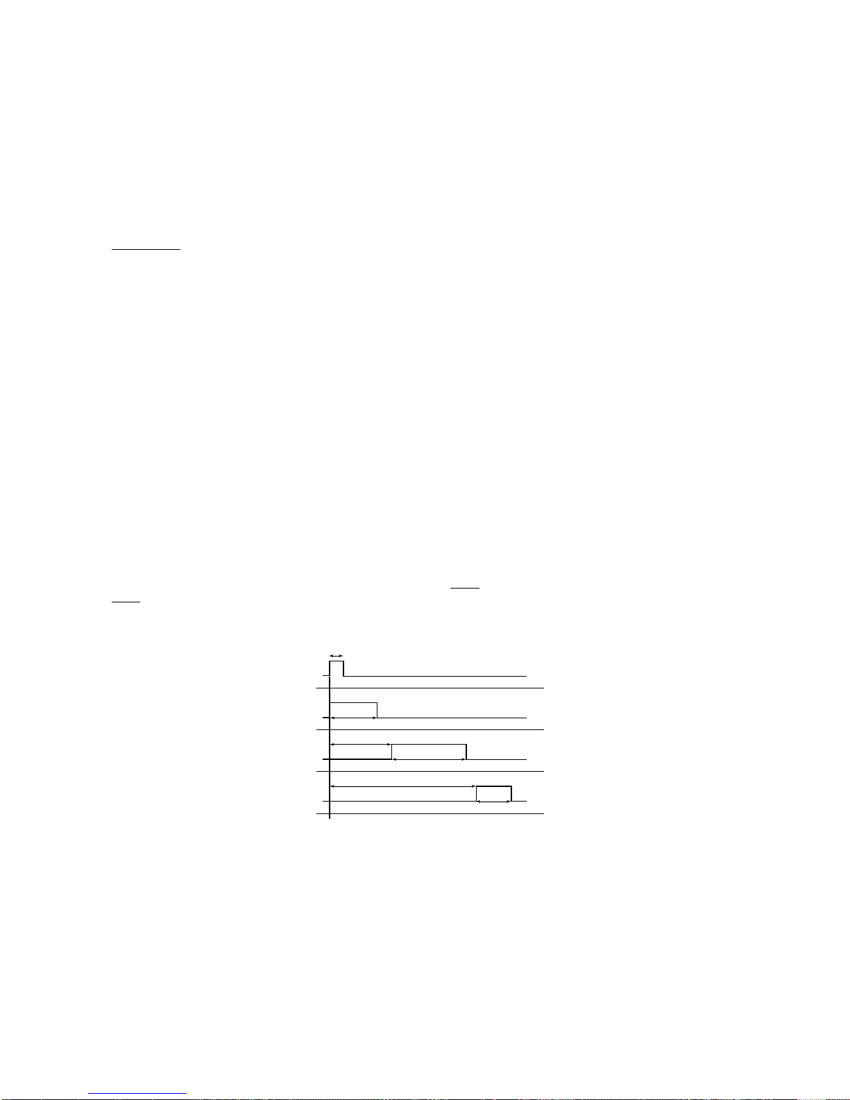
23
powerSplit manual - cod.+030220320 rel. 1.1 - 09/12/02
1: Ingresso associato ad allarme esterno immediato
È possibile collegare all'ingresso digitale un allarme esterno che richiede
intervento immediato (ad esempio allarme di alta pressione o termico
compressore).In particolare l'allarme viene rilevato quando il contatto si
apre (funzionamento regolare con contatto chiuso).L'attivazione dell'allarme
provoca la segnalazione a display (vedi allarme IA), abilitazione del
buzzer, se previsto, e comporta le seguenti azioni sugli attuatori:
compressore: viene spento
ventilatori: continuano a funzionare secondo i parametri ventole (F).
Se l'allarme esterno viene rilevato durante uno sbrinamento o un ciclo
continuo, il controllo esce dalle suddette procedure.
Quando l'allarme cessa, la macchina torna a funzionare in normale
regolazione di temperatura.
Nota impor
tante: si ricorda che per garantire la sicurezza dell'unità in caso
di allarmi gravi, è necessario predisporre sull'unità stessa tutte le sicurezze
elettromeccaniche necessarie a garantire un corretto funzionamento.
2: ingresso associato ad allarme esterno ritardato
Significato, collegamento e modalità di funzionamento sono simili a
quelle già indicate per il parametro A4/A5=1.In questo caso è, però,
possibile ritardare la segnalazione di allarme per un tempo, in minuti,
pari al valore selezionato nel parametro A7.Le azioni su compressore,
ventilatori, sbrinamento e ciclo continuo sono le stesse, dopo il ritardo
impostato, già viste per A4/A5=1.
3: ingresso associato al defrost da contatto
Questa funzione consente di attivare lo sbrinamento da contatto
esterno.Se lo sbr inamento avviene tramite contatto esterno restano
validi tutti i parametri di tipo “d”selezionati. In particolare può essere
utile porre dI=0 ed inibire gli sbrinamenti da RTC (sulle unità Master
dotate di RTC) se si desiderano abilitare solo gli sbrinamenti manuali,
o da contatto esterno.Questa funzione è utile nel caso sia necessar io
eseguire sbrinamenti a tempo reale.Per realizzarli è sufficiente
collegare un timer meccanico o elettronico all'ingresso digitale.Quando
il contatto del timer esterno, meccanico o elettronico, passa da aperto
a chiuso si innesca la richiesta di sbrinamento.Impostando d5 diverso
in ogni unità è possibile collegare piò PSB allo stesso timer, evitando
sbrinamenti contemporanei.
NO
T
A: nel caso di un Master, avente degli Slave asserviti, alla chiusura
del proprio contatto digitale quest’ultimo avvierà un defrost di rete.Se
alla fine del defrost il contatto viene trovato ancora chiuso, viene
eseguito un nuovo defrost.
LEGENDA:
t = impulso del timer per iniziare lo
sbrinamento: la durata minima deve
essere di 1 secondo e la durata
massima inferiore al tempo di defrost.
dP(1) = durata massima sbrinamento unità 1
d5(2) = ritardo sbrinamento da contatto
esterno per l'unità 2. Deve essere
maggiore di dP(1) se non si vuole
sovrapposizione tra gli sbrinamenti
Significati analoghi per d5(3) e dP(3)
4: Switch Porta
All'apertura dell'interruttore della porta vengono spenti il compressore e
le ventole e accese le luci (se un relè è configurato come luce).
Alla chiusura della porta la macchina riprende il precedente
funzionamento, ritardando un eventuale allarme di temperatura per un
numero di ore pari al valore d8.
Se la porta resta aperta per un tempo superiore a d8, il display
visualizza il messaggio “/-“ ed il controllo torna al normale
funzionamento precedente all’apertura della porta.
In particolare:
• se il controllo era in Duty Setting esso ritorna in tale stato;
1: Input associated to an immediate external alarm
An external alarm requiring immediate intervention can be connected
to the digital input (for example, high pressure or compressor thermal
overload alarm). Specifically, the alarm is detected when the contact
opens (normally closed).The activation of the alarm causes a signal on
the display (see alarm IA), activates the buzzer, if fitted, and involves
the following actions on the actuators:
compressor: switched off
fans: continues to operate according to the fan parameters (F).
If the external alarm is detected during a defrost or continuous cycle,
the controller exits the procedure.
When the alarm stops, the machine returns to normal temperature
control.
Important note: remember that to ensure the safety of the unit in the
event of serious alarms, all the electromechanical safety devices
required for correct operation must be fitted.
2: input associated to a delayed external alarm
The meaning, connection and operating mode are similar to that
described for the parameter A4/A5=1.In this case, however, the alarm
signal can be delayed for a time, in minutes, equal to the value set for
parameter A7.The actions on the compressor, fans, defrost and
continuous cycle are the same, after the set delay, as already seen for
A4/A5=1.
3: input associated to the defrost from external contact
This function allows a defrost to be started from an external contact.If
the defrost is started from an external contact, all the type “d”
parameters remain valid.In particular, it may be useful to set dI=0 and
inhibit the RTC defrosts (on the Master units unit fitted with RTC) if only
manual defrosts or defrosts from the external contact are required.
This function is useful for performing real time defrosts. To do this,
simply connect a mechanical or electronic timer to the digital input.
When the external timer contact, mechanical or electronic, is closed,
the defrost request is sent.By setting a different d5 on every unit more
than one PSB can be connected to the same timer, thus avoiding
simultaneous defrosts.
NO
TE: in the case of a Master with Slaves connected, the closing of its
own digital contact will also start a network defrost. If at the end of the
defrost the contact is still closed, a new defrost is performed.
KEY:
t =impulse from the timer to start the
defrost:the minimum duration must
be 1 second, and the maximum
duration less than the defrost time.
dP(1) = maximum duration to defrost unit 1
d5(2) = delay in defrost from external
contact for unit 2.This must be
greater than dP(1), unless
overlapping between defrosts is
required
Similar meanings for d5(3) and dP(3)
4: Door switch
When the door is opened, the compressor and the fans are stopped
and the lights are switched on (if a relay is configured for the light).
When the door is closed, the machine restarts the previous operation,
delaying any temperature alarm by a number of hours equal to the
value d8.
If the door remains open for a time greater than d8, the display shows
the message “/-“ and the controller returns to the normal operating
status before the door was opened.
Specifically:
• if the controller was in Duty Setting mode, it returns to that status;
timer
unit 1
unit 2
unit 3
richiesta sbrinamento
defrost request
t
defrost
dP(1)
defrost
dP(2)
d5(2)
defrost
dP(3)
d5(3)
Fig. 4.3.1
Page 28

24
powerSplit manual - cod.+030220320 rel. 1.1 - 09/12/02
• se il controllo era in ciclo continuo esso riprende a gestirlo ed il
tempo massimo di permanenza rimane lo stesso (ovvero il contatore
continua anche durante l’apertura della porta);
• se il controllo era in defrost questo rimane in defrost;
• se il defrost viene r ichiesto mentre la por ta è aperta, esso viene
ritardato sino alla chiusura della porta
Alla riaccensione del compressore vengono rispettate le eventuali
tempistiche di protezione selezionate (vedi parametri c).
Nota:
con porta aperta si forza lo spegnimento anche nel caso in cui il
ventilatore sia gestito dal regolatore ventole
(parametri F).
5: variazione automatica del Set Point da contatto digitale (Switch
notte)
Contatto chiuso = Set notte
Contatto aperto = Set giorno
In Set notte, al valore impostato del Set Point viene aggiunto il valore
(con segno) impostato nel parametro r4, quindi, il nuovo Set di lavoro
risulta essere: Set giorno + r4.
L’accensione delle luci è associata all’aper tura del contatto digitale se il
relè ausiliario è usato quale interruttore per le luci.
Esempio applicativ
o:
In un sistema Master/Slave per banchi canalizzati è sufficiente
collegare il comando luce ad un ingresso per gestire il comando luce
su tutte le unità.
Nota bene:
In un sistema Master/Slave il Set Point notturno non viene
propagato agli Slave, ma è possibile ottenere lo stesso effetto con
opportuna configurazione
6: On/Off remoto
Contatto chiuso = ON
contatto aperto = OFF
In stato di OFF il controllo visualizza le temperature alternate alla
scritta OFF.
Esso esegue solo un’azione di display delle temperature, non agisce
né sul compressore, né sulle ventole, che sono spenti, né effettua il
monitoraggio di eventuali allarmi.
Lo strumento, inoltre, non reagisce alle richieste di defrost, ciclo
continuo e Duty Setting.Nel caso lo str umento in Off sia un Master con
una sotto rete di Slave, manderà in Off tutta la rete.
Questa condizione va considerata uno standby, ovvero al rientro dalla
condizione (chiusura del contatto) il controllo non avvierà le procedure
legate all’accensione dello strumento (sbrinamento all’accensione
[d4], ritardo partenza compressore [c0], ecc...).
Il comando luce da tastiera è abilitato anche in stato di OFF ed è
prioritario rispetto agli altri comandi di OFF, tastiera e supervisore.
7: ingresso associato ad abilitazione sbrinamento
È possibile collegare un contatto esterno all'ingresso Multifunction per
abilitare o inibire lo sbrinamento.Quando il contatto è aper to lo
sbrinamento è inibito, viceversa il contatto è chiuso lo sbrinamento è
abilitato.Se il contatto è chiuso, ma non vi è una richiesta di defrost,
ovviamente lo sbrinamento non viene effettuato.Se il contatto si apre
mentre è in corso uno sbrinamento, il defrost in corso viene portato a
termine, mentre vengono inibiti gli sbrinamenti successivi, sino alla
chiusura del contatto digitale.Questa funzione è utile, ad esempio, nel
caso di banchi frigoriferi canalizzati con sbrinamento a gas caldo.In
questi impianti è necessario sbrinare per isole per cui, nello stesso
istante, alcune isole sono abilitate a sbrinare, mentre altre sono inibite.
Altro utilizzo della funzione è impedire sbrinamenti delle unità esposte
al pubblico durante il periodo di apertura.
8: Duty Setting da comando esterno
L’apertura del contatto, normalmente chiuso, porta il PSB nella
condizione di Duty Setting, generando l’allarme Id per indicare la
condizione, attivando il buzzer ed il relè di allarme, se presente.
Il comportamento in Duty Setting è analogo a quello il parametro
descritto c4.
• if the controller was in continuous cycle mode, it starts managing this
again and the maximum time remains the same (that is, the counter
also continues when the door is open);
• if the controller was defrosting, it returns to the defrost;
• if the defrost is requested while the door is open, it is delayed until
the door is closed.
When the compressor is re-started, any set protection times are
complied with (see parameters c).
Note:
when the door is open, the fan is stopped even if it is managed
by the fan controller
(F parameters).
5: Automatic Set Point variation from digital contact (night switch)
Contact closed = night-time Set Point
Contact open = day-time Set Point
With the night-time Set Point, the value of the Set Point is added the to
value (including the sign) set for parameter r4, thus the new Set Point
is:day-time Set Point + r4.
The lights are switched on when the digital contact opens, if the auxiliary relay is used as a light switch.
Example:
In a Master/Slave system for multiplexed showcases, simply connect
the light command to an input to manage the lights on all the units.
Important note: In a Master/Slave system, the night-time Set Point is
not sent to the Slaves, however the same effect can be achieved using
a specific configuration.
6: Remote On/Off
Contact closed = ON
contact open = OFF
In OFF status the controller displays the temperature, alternating with
the text OFF.
It only displays the temperature, and does not act on the compressor
or the fans, which are off, or monitor any alarms.
The instrument thus does not react to the defrost, continuous cycle and
Duty Setting requests.If the instrument Off is a Master connected to a
network of Slaves, it switches the entire network Off.
This condition is better considered as standby, that is, when the
condition returns (closing of the contact), the controller will not perform
the instrument start-up procedure (defrost on star t-up [d4], start
compressor delay [c0], etc....).
The light command from the keypad is also enabled in OFF status.
This command has priority over the other OFF commands, from the
keypad and the supervisor.
7: Enable defrost input
An external contact can be connected to the multifunction input to
enable or inhibit the defrost function.
When the contact is open, the defrost is inhibited, vice-versa it is
enabled when the contact is closed.
If the contact is closed and there is no request from the controller,
obviously the defrost is not performed.If the contact opens while a
defrost is in progress, the defrost is stopped, while the subsequent
defrosts are inhibited, until the closing of the digital contact.
This function is useful, for example, in the case of multiplexed showcases with hot gas defrost.These systems must be defrosted by islands
and thus, at any one moment, some islands are enabled for defrost,
while others are inhibited.Another use of the function is to prevent
defrosting the units accessed by the public during opening hours.
8 : Duty Setting from external command
The contact, normally closed, when opened activates the duty setting
mode on the PSB;the Id alarm is displayed to indicate the condition,
the buzzer sounds and the alarm relay (if fitted) is activated.
The behaviour in duty setting mode is similar to that described for
parameter c4.
Page 29

25
powerSplit manual - cod.+030220320 rel. 1.1 - 09/12/02
9: Switch Porta (con compressore ON)
Questa opzione ha le stesse caratteristiche di Switch Porta con la sola
differenza che, in questo caso, l’apertura del contatto, provoca la
fermata delle ventole ma non del compressore.
Questa funzione può essere utile in quei casi in cui l’apertura della
porta può essere frequente (armadi frigo, piccole celle di alimentari,
espositori BT con porta, ecc...). Di conseguenza l’interruzione
altrettanto frequente del compressore comporterebbe, oltre a problemi
relativi alla vita del compressore stesso, se non adeguatamente
protetto, anche problemi di raffreddamento.
Ingresso vir
tuale (solo per sistemi Master/Slave)
Un’altra delle possibilità offerte dai controlli PSB è quella di poter
configurare l’ingresso DIN 2 come ingresso virtuale asservito al Master.
Il concetto è il seguente:lo stato dell’ingresso DIN 2 del Master può
essere propagato via LAN, le unità Slave possono condizionare il loro
funzionamento sullo stato di DIN 2 propagato, se opportunamente
programmate.
Attenzione:se si abilita questo meccanismo l’ingresso fisico DIN 2
degli Slave diviene ininfluente, mentre ne viene usato il significato logico.Per ulteriori chiarimenti vedi parametro Ld.
Alcune a
vvertenze importanti
Per una corretta gestione delle funzionalità associate agli ingressi
digitali, i valori di A4 e A5 devono essere tutti distinti tra loro, cioè
A4≠A5, oppure devono essere nulli, A4/A5 =0.
Di default A4 e A5 valgono zero e, quindi, i corrispondenti ingressi non
sono associati ad alcuna funzionalità.
Nota:
Dopo aver configurato gli ingressi digitali del controllo, procedere
ad un reset.
Il mancato rispetto delle suddette avvertenze può causare anomalie
nel funzionamento dei controlli sia in installazioni stand-alone che in
installazioni di rete.
A7: Ritardo rilevazione dell'allarme esterno (ingresso Multifunction)
Stabilisce il ritardo (in minuti) al rilevamento dell'allarme esterno
quando A4/A5=2.
- Def.: 0
4.4 c = parametri per la gestione del compressore
9 : Door switch (with compressor ON)
This option has the same characteristics as Switch Port, with the only
difference that in this case, the opening of the contact stops the fans,
but not the compressor.
This function may be useful in cases where the door may be opened
frequently (refrigerated cabinets, small cold rooms, LT display cabinets
with doors, etc....).And as a consequence the frequent stopping of the
compressor would lead to problems with the life of the compressor
unless adequately protected, as well as cooling problems.
Vir
tual input (only for Master/Slave systems)
Another function offered by the PSB controllers is the possibility of
configuring input DIN 2 as a virtual input on the Master.
The concept is as follows:the status of the input DIN 2 on the Master
can be sent via the LAN, and the Slave units can change their
operation according to the status of DIN 2 as received, if suitably
programmed.
Caution:if this mechanism is enabled, the physical input DIN 2 on the
Slaves becomes ineffective, while its logical meaning is used.For
further explanation, see parameter Ld.
Some impor
tant warnings
For the correct management of the functions associated to the digital
inputs, the values of A4 and A5 must different, that is, A4≠A5, or
alternatively must be null A4/A5 = 0.
As default A4 and A5 are set to zero and, thus, the corresponding
inputs are not associated to any function.
Note:
After having configured the digital inputs on the controller, it
should be reset.
The failure to heed the above-mentioned warnings may cause
operating anomalies in the controllers, in both stand-alone and network
installations.
A7: External alarm delay (Multifunction input)
Sets the delay (in minutes) for detecting the external alarm when
A4/A5=2.
- Def.: 0
4.4 c = Compressor management parameters
cPARAMETRI COMPRESSORE Tipo Min Max U.M. Def.
c0 Ritardo partenza compressore all’accensione dello strumento C 0 15 min 0
c1 Tempo minimo tra due accensioni successive del compressore C 0 15 min 0
c2 Tempo minimo di spegnimento del compressore C 0 15 min 0
c3 Tempo minimo di funzionamento del compressore C 0 15 min 0
c4 Sicurezza relè (0 = compressore sempre OFF,
100 = compressore sempre ON) Duty Setting C 0 100 min 0
c6 Tempo esclusione allarme di bassa temp.dopo ciclo continuo C 0 15 ore 2
cc Durata ciclo continuo C 0 15 ore 4
cPARAMETRI COMPRESSORE Tipo Min Max U.M. Def.
c0 Ritardo partenza compressore all’accensione dello str umento C 0 15 min 0
c1 Tempo minimo tra due accensioni successive del compressore C 0 15 min 0
c2 Tempo minimo di spegnimento del compressore C 0 15 min 0
c3 Tempo minimo di funzionamento del compressore C 0 15 min 0
c4 Sicurezza relè (0 = compressore sempre OFF,
100 = compressore sempre ON) Duty Setting C 0 100 min 0
c6 Tempo esclusione allarme di bassa temp.dopo ciclo continuo C 0 15 ore 2
cc Durata ciclo continuo C 0 15 ore 4
Page 30
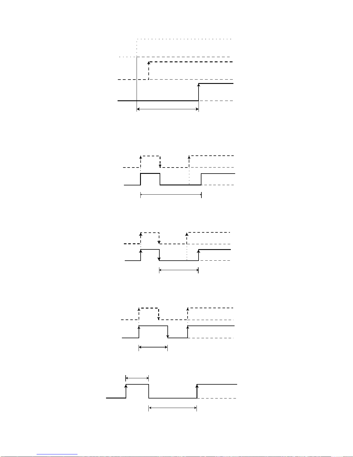
26
powerSplit manual - cod.+030220320 rel. 1.1 - 09/12/02
c0: Ritardo inserimento del compressore e delle ventole (se
gestite) dall'accensione strumento
Dal momento in cui viene
alimentato il controllo, l'accensione
del compressore e delle ventole
(se gestite) viene ritardata di un
tempo (in minuti) pari al valore
assegnato a questo parametro.
Questo ritardo consente di
proteggere il compressore da
ripetute accensioni nel caso di
frequenti cadute di tensione.Ad
es., ponendo c0=6 si obbliga il
compressore ad attendere 6 minuti
prima di partire dal momento in
cui è ritornata la tensione. Nel
caso di impianti con più compressori, il parametro c0 può essere usato
anche per evitare partenze contemporanee di più unità, impostando per
ogni compressore un diverso valore di “c0”.
- Def.:0
c1:Tempo minimo tra 2 accensioni successive del compressore
Stabilisce il tempo minimo (in
minuti) che deve trascorrere tra
due accensioni del compressore,
indipendentemente dalla temperatura e dal Set Point.Settando questo parametro è possibile limitare il
numero di accensioni per ora.Ad
esempio se il numero di
inserimenti ora massimo consentito
è pari a 10, basta impostare c1=6 per garantire il rispetto di questo limite.
- Def.:0
c2:Tempo minimo di spegnimento del compressore
Stabilisce il tempo minimo (in minuti)
di spegnimento del compressore.
Questo non viene riacceso se non è
trascorso dall'ultimo spegnimento il
tempo minimo selezionato c2.
Questo parametro è utile per
garantire l'equalizzazione delle
pressioni dopo lo spegnimento nel
caso di impianti con compressori
ermetici e capillari.
- Def.:0
c3:Tempo minimo di accensione del compressore
Stabilisce il tempo minimo (in
minuti) di accensione del
compressore.Questo non viene
spento se non è rimasto acceso
per un tempo pari al minimo
selezionato.
- Def.:0
c4: Duty Setting o sicurezza relè
Nel caso si verifichi l'allarme “rE”,
errore di regolazione, (ovvero
sonde S1 e/o S3 in cortocircuito
o sconnesse) questo parametro
permette di assicurare il
funzionamento del compressore
in attesa dell'eliminazione del
guasto.In pratica il compressore,
non potendo essere azionato in
base alla temperatura (a causa della/e sonda/e guasta/e), viene fatto
funzionare ciclicamente con un tempo di funzionamento (tempo di ON)
c0: Compressor and fan (if managed) start delay when the
instrument is turned on
At the moment the controller is
turned on, the start-up of the
compressor and the fans (if
managed) is delayed by a time
(minutes) equal to the value
assigned to this parameter. This
delay allows the compressor to
be protected against repeated
starts in the case of frequent
power failures.For example,
setting c0=6 forces the
compressor to wait 6 minutes
before starting from when the
power returns.In the case of
systems with more than one compressor, parameter c0can also be
used to avoid simultaneous start-ups of the units, setting for each
compressor a different value for “c0”.
- Def.:0
c1: Minimum time between 2 successive starts of the compressor
Sets the minimum time (in
minutes) that must elapse
between two start of the
compressor, irrespective of the
temperature and the Set Point.
Setting this parameter can limit
the number of starts per hour.
For example, if the maximum
number of starts allowed per
hour is 10, simply set c1=6 to ensure this limit is respected.
- Def.:0
c2: Minimum compressor off time
Sets the minimum time (in minutes)
that the compressor stays off.
This is not re-started until the
minimum time selected c2 has
passed since the last shut-down.
This parameter is useful in
ensuring pressure equalisation
after shut-down.
- Def.:0
c3: Minimum compressor on time
Sets the minimum time the
compressor stays on.This is not
shut-down unless it has been on
for the minimum time selected.
- Def.:0
c4: Duty Setting or safety function
In the event of the alarm “rE”
(that is, probes S1 and/or S3
are short-circuited or
disconnected) this parameter
ensures the operation of the
compressor until the fault is
resolved.In practice, the
compressor, not being able to
be activated according to the
temperature (due to the probe fault/faults), works cyclically with an ON
time equal to the value assigned to parameter c4 (in minutes) and a
richiesta inserimento
insertion request
compressore
compressor
C3
ON
ON
OFF
OFF
C4
compressore
compressor
OFF = 15 min.
ON
OFF
richiesta inserimento
insertion request
compressore
compressor
C2
ON
ON
OFF
OFF
accensione strumento
power ON
richiesta intervento
insertion request
compressore
compressor
C0
ON
ON
ON
OFF
OFF
OFF
richiesta inserimento
insertion request
compressore
compressor
C1
ON
OFF
OFF
ON
Page 31

27
powerSplit manual - cod.+030220320 rel. 1.1 - 09/12/02
pari al valore assegnato al parametro c4 (in minuti) e un tempo di
spegnimento (tempo di OFF) fisso di 15 minuti.
Esistono due valori di c4 che causano comportamenti particolari:
• se c4 = 0 il compressore rimane sempre spento;
• se c4 = 100 il compressore rimane sempre acceso; non vengono cioè
mai considerati i 15 minuti di spegnimento.
Si considerino inoltre queste situazioni particolari:
- se l'errore di regolazione avviene mentre il compressore è spento,
esso viene acceso, rispettando le tempistiche selezionate con i
parametri c1 e c2, e rimane in funzionamento per un tempo pari a c4.
Inizia quindi il funzionamento con “duty setting”.
Le ventole continuano a funzionare secondo i parametri selezionati (F).
- se l'errore di regolazione è rilevato mentre il compressore è acceso,
esso viene spento (senza rispettare il tempo min.di funzionamento
eventualmente selezionato con il parametro c3) e rimane spento per
15 minuti.
Dopo di ciò inizia il funzionamento periodico con tempo di
funzionamento pari al valore di c4.
- se l'errore di regolazione avviene mentre il controllo si trova in
sbrinamento o in ciclo continuo, il controllo esce istantaneamente
dallo stato in cui si trova e attiva il funzionamento “duty setting”.
Se l’errore dovesse persistere è necessario ripristinare il corretto
funzionamento di entrambe le sonde S1 ed S3 (nel caso in cui la
regolazione avvenisse con sonda virtuale su entrambe) mediante
apertura quadro e verifica delle connessioni elettriche. Si tenga
presente che, in caso di errore di regolazione su di un’unità
Master/Slave, non è possibile eseguire localmente né gli sbrinamenti
manuali né il ciclo continuo.
Dopo il Duty Setting vengono esclusi per 5 minuti gli allarmi di
temperatura.
- Def.:0
c6: Esclusione allarme dopo ciclo continuo
È il tempo, (in ore), in cui l'allarme di bassa temperatura non viene più
monitorato dopo un ciclo continuo.In pratica se la temperatura
dell'unità refrigerata dovesse, dopo il ciclo continuo, abbassarsi per
inerzia sotto il livello di minima temperatura (Set Point - AL) si ritarda
del tempo c6 impostato il monitoraggio del relativo allarme.
Teoricamente, il permanere di una condizione di allarme di bassa
temperatura, verificatosi alla fine del ciclo continuo, verrebbe rivelato
dopo il trascorrere di un tempo pari alla somma di “c6”hh + “Ad ”mm
(parametro Ad:ritardo in minuti di segnalazione di una condizione di
bassa/alta temperatura).Si ricorda che alla temperatura (set point - AL)
il ciclo continuo viene forzatamente disattivato.
- Def.:2.
cc : Durata ciclo continuo
È il tempo (in ore) in cui il compressore rimane in continua attività per
abbassare la temperatura anche sotto il set point.Il controllo esce dalla
procedura dopo che è trascorso il tempo impostato per il parametro cc
o per raggiungimento della temperatura minima prevista:(set point - AL).
Se AL=0 il ciclo continuo termina al raggiungimento del setpoint.
Se cc≠0 il ciclo continuo non viene attivato.
Per il funzionamento in rete vedi capitolo “Il ciclo continuo di rete”.
- Def.:4
fixed OFF time of 15 minutes.
There are two values for c4 which create special conditions:
• if c4 = 0 the compressor is always off;
• if c4 = 100 the compressor is always on;that is, the 15 minute
shut-down is ignored.
These special situations should also be considered:
- if the control error occurs while the compressor is off, it is started,
respecting the times set by parameters c1 and c2, and remains on for
a time equal to “c4”.
“Duty setting”operation then starts.
The fans continue to operate according to the set parameters (F).
-f the control error occurs while the compressor is on, it is stopped
(without respecting the minimum on time, if set by parameter c3) and
remains off for 15 minutes.
After that, cyclical operation starts, with an on time equal to the value
of c4.
- if the control error occurs while the controller is in defrost or
continuous cycle mode, the controller instantly exits the current status
and activates “duty setting”operation. If the error persists, the correct
operation of both probes, S1 and S3, must be reset (in the event
where control is performed using the virtual probe on both) by
opening the panel and checking the electrical connections.It should
be remembered that, in the event of a control error on Master/Slave
units, the manual defrosts or the continuous cycle cannot be
performed locally.
After Duty Setting operation, the temperature alarms are ignored for
5 minutes.
- Def.:0
c6: Alarm bypass after continuous cycle
This is the time, (in hours), that the low temperature alarm is disabled
after a continuous cycle.In practice, if the temperature of the
refrigeration unit, after the continuous cycle, falls due to inertia below
the minimum temperature level (Set Point - AL) the activation of the low
temperature alarm is delayed for a time equal to c6.Theoretically, the
low temperature alarm condition occurring at the end of the continuous
cycle would be detected only after a time equal to the sum of “c6”hh +
“Ad”mm (parameter Ad:delay, in minutes, for signalling a low/high
temperature condition) Remember that at the minimum temperature
(Set Point - AL) the continuous cycle is forced off.
- Def.:2.
cc : Continuous cycle duration
This is the time (in hours) that the compressor stays continuously on in
order to lower the temperature to or below the Set Point.The control
exits the procedure after the time set for the parameter cc or when the
minimum temperature has been reached (set point - AL).
If AL=0, the continuous cycle ends when the set point is reached.
If cc≠0 the continous cycle is not activated.
For network operation, see the chapter “Network continuous cycle”.
- Def.:4
Page 32

28
powerSplit manual - cod.+030220320 rel. 1.1 - 09/12/02
4.5 d = parametri per la gestione dello sbrinamento
d0:Tipo di sbrinamento
Stabilisce il tipo di sbrinamento:
0 = a resistenza:finisce in temperatura e/o per timeout
1 = a gas caldo:finisce in temperatura e/o per timeout
2 = a resistenza:finisce per timeout
3= a gas caldo:finisce per timeout
- Def.:0.
d2:Tipo di comando di defrost
Il parametro configura la risposta della macchina ad una richiesta di
defrost da rete e può assumere i seguenti valori:
0 = solo start
1 = start e stop da rete
Se il parametro è posto a 0, a seguito di una richiesta di defrost da rete
il sistema al termine del defrost riprenderà il normale funzionamento.
Se, invece, il parametro è posto a 1, a seguito di una richiesta di
defrost da rete il sistema al termine del defrost attenderà dal Master il
consenso a riprendere il normale funzionamento.Se il consenso non
viene dato entro il tempo impostato dal parametro dP + 5 min., il sistema allo scadere di questo tempo riprende il normale funzionamento.Il
parametro è utile per poter integrare il PSB anche in sistemi che non
prevedono i defrost completamente sincronizzati, ma solo con partenza
sincronizzata.
Nota bene:
In un sistema canalizzato Master/Slave il parametro deve
essere impostato a 1 anche nell’unità Master.
- Def :0
4.5 d = Defrost management parameters
d0:Type of defrost
Establishes the type of defrost:
0 = electric heater: ends by temperature and/or timeout
1 = hot gas:ends by temperature and/or timeout
2 = electric heater: ends by timeout
3= hot gas:ends by timeout
- Def.:0.
d2 :Type of defrost control
This parameter configures the response of the machine to a network
defrost request and can have the following values:
0 = start only
1 = network start and stop
If the parameter is set to 0, following a network defrost request the
system returns to normal operation at the end of the defrost.
If the parameter is set to 1, following a network defrost request the
system, at the end of the defrost, waits for the Master to send the
signal to return to normal operation. If the signal is not sent within the
time set by parameter dP + 5 minutes, the system then restarts normal
operation.This parameter is useful for integrating the PSB in systems
that do not feature completely synchronised defrosting, but only synchronised starts.
Impor
tant note: In a multiplexed Master/Slave system, the parameter
must also be set to 1 on the Master unit.
- Def :0
dPARAMETRI SBRINAMENTO Tipo Min Max U.M. Def.
d0 Tipo di sbrinamento
0 = a resistenza:finisce in temperatura e/o per timeout
1 = a gas caldo:finisce in temperatura e/o per timeout
2 = a resistenza:finisce per timeout
3 = a gas caldo:finisce per timeout C 0 3 - 0
d2 tipo di comando da rete C 0 1 flag 0
d4 Sbrinamento all’accensione dello strumento (0 = No, 1 = Si) C 0 1 flag 0
d5 Ritardo sbrinamento all’accensione dello strumento o da ingresso digitale C 0 199 min 0
d6 Gestione display principale e display remoto durante il defrost:
0 = No blocco visualizzazione e temperatura alternata al simbolo “dF”su entrambi i display
1 = blocco visualizzazione su entrambi i display C 0 1 flag 1
d8 Tempo esclusione allarme di alta temperatura dopo il defrost
e se (A4 /A5 =4) tempo di esclusione allarme dall’apertura della por ta F 0 15 ore 1
d9 Priorità defrost sulle protezioni del compressore (0 = No, 1 = Si) C 0 1 flag 0
dd Tempo di gocciolamento dopo lo sbrinamento F 0 15 min 2
dI Intervallo tra due sbrinamenti F 0 199 ore 8
dP Massima durata di uno sbrinamento F 1 199 min 30
dt Temperature di fine sbrinamento F -50 +199 ˚C/˚F 4.0
d DEFROST PARAMETERS Type Min Max UOM Def.
d0 Type of defrost
0 = electric heater: ends by temperature and/or timeout
1 = hot gas:ends by temperature and/or timeout
2 = electric heater: ends by timeout
3 = hot gas:ends by timeout C 0 3 - 0
d2 type of network control C 0 1 flag 0
d4 Defrost on instrument start-up (0 = No, 1 = Yes) C 0 1 flag 0
d5 Defrost delay on instrument start-up or from digital input C 0 199 mins 0
d6 Management of main and remote display during defrost:
0 = displays on, temperature alternating with the symbol “dF”on both displays
1 = both displays off C 0 1 flag 1
d8 High temperature alarm bypass time after defrost
and if (A4 /A5 =4) alarm bypass time from the opening of the door F 0 15 hours 1
d9 Priority of defrost over compressor protection (0 = No, 1 = Yes) C 0 1 flag 0
dd Dripping time after defrosting F 0 15 mins 2
dI Interval between two defrosts F 0 199 hours 8
dP Maximum defrost duration F 1 199 mins 30
dt End defrost temperature F -50 +199 ˚C/˚F 4.0
Page 33

29
powerSplit manual - cod.+030220320 rel. 1.1 - 09/12/02
d4: Sbrinamento all'accensione dello strumento
Attiva uno sbrinamento all'accensione dello strumento.
0 = non c'è sbrinamento all'accensione dello strumento;
1 = viene eseguito uno sbrinamento all'accensione dello strumento.
Forzare uno sbrinamento all'accensione dello strumento può essere
utile in situazioni molto particolari, ad es. se nell'impianto si verificano
frequenti cadute di tensione.Infatti, in caso di mancanza di tensione lo
strumento azzera il timer interno che calcola l'intervallo tra due
sbrinamenti, ripartendo da zero. Se la frequenza della caduta di
tensione fosse, per assurdo, maggiore della frequenza di sbrinamento
(per es.una caduta di tensione ogni 8 ore contro uno sbr inamento ogni
10 ore) il controllo non sbrinerebbe mai.In una situazione di questo
tipo è preferibile attivare lo sbrinamento all'accensione, soprattutto se
questo è controllato in temperatura (sonda sull'evaporatore) per cui si
evitano sbrinamenti inutili o, quantomeno, si riducono i tempi di
esecuzione.Nel caso di impianti con molte unità, se si seleziona la
partenza in sbrinamento potrebbe succedere, dopo una caduta di
tensione, che tutte le unità partano in sbrinamento, Causando
sovraccarichi di corrente.Per ovviare a ciò si può sfruttare il parametro
d5 che permette di inserire un ritardo prima dello sbrinamento, che
ovviamente diverso per ogni unità.
NOTA: Un’unità Master, avente degli Slave asserviti, con “d4 = 1”
tenterà ad ogni accensione, dopo il Power-Up, di eseguire un defrost di
rete.In questa configurazione è consigliabile impostare “d4 = 0” nelle
unità Slave in modo che il defrost al Power-Up sia comandato
esclusivamente dal Master.
- Def.:0.
d5: Ritardo sbrinamento all'accensione dello strumento o da
ingresso Multifunction
Rappresenta il tempo (in minuti) che deve intercorrere tra l'accensione
del controllo e l'inizio dello sbrinamento.Nel caso l'ingresso digitale sia
utilizzato per abilitare lo sbrinamento (vedi parametri A4/A5 = 3) o per
avviare uno sbrinamento da contatto esterno (vedi parametri A4/A5=4),
questo parametro rappresenta il ritardo tra l'abilitazione dello sbrinamento, o la sua richiesta, e l'inizio effettivo.L'ingresso digitale di
sbrinamento (vedi parametri A4/A5) può essere proficuamente usato
per eseguire sbrinamenti in tempo reale, collegandovi un timer
ESTERNO.
Lo sbrinamento sarà attivato alla chiusura del contatto del timer.
Nel caso di più unità collegate allo stesso timer si suggerisce di usare
il parametro d5 per ritardare i vari sbrinamenti, evitando, quindi,
sovraccarichi di corrente.Inoltre, per non usare sbrinamenti indesiderati comandati dall'orologio interno dello strumento si suggerisce di settare il parametro dI=0 su tutte le unità e di inibire gli sbrinamenti ad orari
programmati sulle unità configurate come Master e dotate di RTC (solo
sbrinamenti manuali da tastiera o da contatto Multifunction o da
Supervisore/Masterplant).
- Def.:0
d6: Gestione display strumento e display remoto durante lo
sbrinamento
Le opzioni sono 2:
0 = No blocco visualizzazione e temperatura alternata al simbolo “dF”
su entrambi i display
1 = blocco su entrambi i display all’ultimo valore visualizzato prima
dell’inizio del defrost.
Vale anche se la sonda visualizzata è la sonda di defrost.
La visualizzazione riprende normalmente su entrambi i display al termine
del post-gocciolamento (con attività di normale regolazione in atto).
- Def.:1
d8:Tempo esclusione allarmi dopo sbrinamento e/o porta aperta
Indica il tempo (in ore) di esclusione della segnalazione di allarme alta
temperatura dalla fine di uno sbrinamento e/o dopo che è stata aperta
la porta della cella, nel caso che l'ingresso Multifunction sia collegato
allo Switch Porta (vedi parametri A4/A5).Trascorso il quale, viene
visualizzato l’allarme “/-“ indicante la porta aperta.
Se impostato a 0 l’allarme porta è disabilitato.
- Def.:1.
d4 : Defrost on instrument start-up
Activates a defrost cycle when the instrument is turned on.
0 = no, no defrost is performed when the instrument is turned on;
1 = yes, a defrost cycle is performed when the instrument is turned on.
Forcing a defrost cycle when the instrument is turned on may be u
seful in special situations, e.g.if the system is subject to frequent
power failures.In fact, in the event of power failures the instrument's
internal timer, which calculates the interval between two defrosts, is
reset to zero.If the frequency of the power failure were, absurdly,
greater than the defrost frequency (e.g.a power failure every 8 hours
against a defrost every 10 hours), the control would never perform a
defrost.In this type of situation it is better to activate the defrost when
the unit is turned on, above all if the defrost is controlled by
temperature (probe on the evaporator), so as unnecessary defrosts
are avoided or at least reduced in time.In the case of systems with
many units, if defrost on start-up is selected, after a power failure all
the units will start a defrost.This may cause current overloads.To avoid
this, use parameter d5 to set a delay before the defrost starts, which
obviously different for each unit.
NOTE:A Master unit with Slaves connected, with “d4 = 1”, will, at each
power-up, attempt to perform a network defrost. In this configuration,
“d4”should be set to 0 on the Slave units, so that the defrost at
power-up is controlled exclusively by the Master.
- Def.:0.
d5: Defrost delay when the instrument is switched on or from the
Multifunction input
Represents the time which must elapse between when the control is
turned on and the start of the defrost. In the case where the digital
input is used to enable the defrost (see parameters A4/A5 = 3) or to
start a defrost from an external contact (see parameters A4/A5=4), this
parameter represents the delay between the enabling of the defrost, or
its request, and the effective start of the cycle.The defrost from digital
input (see parameters A4/A5) can be exploited to perform defrosts in
real time, connecting an external timer.The defrost will be activated
when the timer contact is closed.In the case where more than unit is
connected to the same timer, it is recommended to set parameter d5
so as to delay the defrosts to a different time for each unit, to avoid
current overloads.Further more, to avoid unnecessary defrosts
controlled by the instrument's internal clock, it is suggested to set
parameter dI=0 on all the units, and to inhibit the timed defrosts on the
unit configured as the Master with RTC (only manual defrosts from the
keypad, or from the Multifunction contact, or from the
supervisor/Masterplant).
- Def.:0
d6: Instrument display and remote display management during
defrosts
There are two options:
0 = Displays on and temperature alternating with the symbol “dF”on
both displays
1 =both displays off, showing the last value displayed before the start
of the defrost.
This is valid even if the probe displayed is the defrost probe.
Both displays restart normally at the end of the post-dripping phase
(in normal control operation).
- Def.:1
d8: Alarm bypass time after defrost and/or door open
This indicates the bypass time for the high temperature alarm signal
from the end of a defrost and/or after the cold room door has been
opened, if the Multifunction input is connected to the “door switch”(see
parameters A4/A5).After this time has elapsed, the alar m is displayed
indicating that the door is open.
If set to 0, the door alarm is disabled.
- Def.:1.
Page 34

30
powerSplit manual - cod.+030220320 rel. 1.1 - 09/12/02
d9: Priorità sbrinamento sulle protezioni compressore
Annulla i tempi di protezione del compressore (c1:tempo minimo tra 2
accensioni successive, c2:tempo minimo di spegnimento e c3: tempo
minimo di funzionamento) all'inizio dello sbrinamento.
0 = i tempi di protezione sono rispettati
1 = i tempi di protezione non sono rispettati.
È utile, ad esempio, nello sbrinamento a gas caldo per evitare di
ritardare l'effettuazione dello sbrinamento nel caso in cui il compressore
si sia appena spento e sia attivato un tempo minimo tra due inserimenti.
Si ricordi però che in questa evenienza potrebbe non essere rispettato
il numero massimo di inserimenti ora del compressore.
- Def.:0
dd:Tempo di gocciolamento
Questo parametro permette di forzare la fermata (in min.) del
compressore e delle ventole dell'evaporatore dopo uno sbrinamento,
al fine di favorire il gocciolamento dell'evaporatore.Se dd = 0 non è
previsto nessun tempo di gocciolamento per cui alla fine dello
sbrinamento viene immediatamente riattivato il compressore.
- Def.:2.
dI: Intervallo tra gli sbrinamenti ciclici
Il parametro dI gestisce gli sbrinamenti detti “ciclici”di ogni singola
unità Master/Slave.Tali sbrinamenti vengono effettuati allo scadere di
un timer, interno allo strumento, caricato al valore memorizzato nel
parametro dI.Tale timer viene ricaricato ogniqualvolta venga tentata
l’effettuazione di un defrost (anche non ciclico).Se il tempo “dI” è pari a
0 gli sbrinamenti di tipo ciclico vengono inibiti.Gli sbrinamenti ciclici
possono essere di tipo locale (cioè effettuati sulle singole unità in maniera
indipendente), ma anche di rete:allo scadere del tempo “dI” su un
Master con degli Slave asserviti, il Master gestirà un defrost di rete.
Durante lo sbrinamento sono inibiti gli allarmi di temperatura.
- Def.:8
dP: Durata massima sbrinamento
Determina la durata massima (in minuti) dello sbrinamento.Questo
parametro rappresenta la durata effettiva dello sbrinamento quando d0
assume il valore =2 o =3 oppure il limite massimo per d0= 0 o 1.Se
l’unità è Master questo parametro determina anche il tempo massimo
per gli slave per terminare il defrost.Da quando il Master termina il
defrost gli Slave hanno al massimo dP + 5 minuti per completare lo
sbrinamento, in caso contrario il Master forzerà la conclusione della
fase di defrost.
- Def.:30
dt: Set Point temperatura di fine sbrinamento
Questo parametro permette di fissare la temperatura dell'evaporatore
alla quale si vuole termini lo sbrinamento (la temperatura
dell'evaporatore è rilevata dalla sonda di defrost: sonda 2).Se all'inizio
di uno sbrinamento (d0 = 0) la temperatura rilevata dalla sonda di
defrost è maggiore di quella impostata come fine sbrinamento, l’unità
passa direttamente in postgocciolamento (Vd.più indietro il defrost di
rete).Nel caso di malfunzionamento della sonda di sbrinamento il
controllo esegue uno sbrinamento a tempo con durata pari al valore
impostato per dP. Così pure se il set point di fine sbrinamento non è
raggiungibile, lo sbrinamento viene interrotto dopo una durata massima
pari al valore, in minuti, di dP e viene visualizzato Ed (se r3=1) che
permane fino a quando viene eseguito uno sbrinamento
“correttamente” finito in temperatura.Nel caso in cui si usi la sonda S3
quale sonda di defrost su un secondo evaporatore, il defrost in
temperatura ha termine quando entrambe le sonde, S2 ed S3, rilevano
una temperatura superiore o uguale a quella memorizzata nel
parametro “dt”.
- Def.:4.0
d9: Defrost priority over compressor protection
Overrides the compressor protection times (c1:minimum time between
2 successive starts, c2:minimum off time and c3: minimum on time) at
the start of the defrost.
0 = the protection times are respected
1 = the protection times are overridden.
This is useful, for example, with hot gas defrost to avoid delaying the
defrost in the case where the compressor has just stopped and there is
a minimum time between two starts.Remember, however, that in this
case the maximum number of starts per hour of the compressor may
not be respected.
- Def.:0
dd: Dripping time
This parameter forces the compressor and the evaporator fans off after
a defrost, in order to allow the evaporator to drip.The value of the
parameter indicates the number of minutes for the pause;if dd=0 there
is no dripping time, therefore the compressor is started immediately at
the end of the defrost.
- Def.:2.
dI: Interval between cyclical defrosts
The parameter dI manages the so-called “cyclical”defrosts for each
Master/Slave unit. The defrost is performed per iodically at an inter val
equal to the value of dI.The interval “dI”is reset whenever a defrost is
attempted (including non-cyclical defrosts).If the time “dI” is equal to 0,
cyclical defrosts are not performed.The cyclical defrosts can be local
(that is, performed on the individual unit independently), or networked:
when the time “dI”has elapsed on a Master with Slaves connected, the
Master will manage a network defrost.The temperature alarm is
inhibited during defrosts.
- Def.:8
dP: Maximum defrost duration
Determines the duration of the defrost (in minutes).This parameter
represents the duration effective of the defrost when has a value:=2 or
=3, or alternatively the maximum limit for d0 = 0 or 1.If the unit is a
Master, this parameter also determines the maximum time for the Slave
to end the defrost.From when the Master ends its defrost, the Slave
has a maximum of dP + 5 minutes to complete its defrost, otherwise
the master will force the end defrost.
- Def.:30
dt: End defrost temperature Set Point
This parameter allows an evaporator temperature to be set at which the
defrost is stopped (the evaporator temperature is measured by the
defrost probe:probe 2). If, at the start of a defrost cycle (d0 = 0), the
temperature measured by the defrost probe is greater than the set end
defrost value, the unit goes directly to the post-dripping phase (see
network defrost, above).In the event of a defrost probe failure, the
control performs a timed defrost with a duration equal to the value set
for dP.The same is true if the end defrost Set Point can not be
reached, the defrost is stopped after a maximum time equal to the
value, in minutes, of dP, and the Ed is displayed (if r3=1) and stays on
until a defrost cycle is “correctly”ended by temperature.In the event
where probe S3 is used as a defrost probe on a second evaporator,
the temperature defrost ends when both probes, S2 and S3, measure
a temperature that is greater than or equal to the value saved by
parameter “dt”.
- Def.:4.0
Page 35

31
powerSplit manual - cod.+030220320 rel. 1.1 - 09/12/02
4.6 F = parametri per la gestione delle ventole dell'evaporatore
F0:Ventole sottoposte al regolatore ventole
Le ventole possono essere sottoposte al regolatore ventole cioè
gestiste in funzione della temperatura rilevata dalla sonda di sbrinamento.
In alternativa le ventole funzionano sempre con la possibilità di spegnerle
quando il compressore è fermo (vedi parametro F2), durante lo
sbrinamento (vedi parametro F3), durante un periodo di gocciolamento
(vedi parametro dd) e per un ulteriore periodo di post gocciolamento
(vedi parametro Fd).I valori ammessi per questo parametro sono:
F0 = 0 :in questo caso le ventole non sono sottoposte al regolatore
ventole ma ai parametri F2, F3 e Fd.
F0 = 1 :le ventole sono sottoposte al regolatore ventole (vedi param.F1)
Nota:
Si ricorda che se è previsto un periodo di gocciolamento
(dd ≠ 0), le ventole vengono comunque spente.
- Def.:0.
F1: (Set Assoluto) Temperatura spegnimento ventole (parametro
operativo solo se F0=1).
Le ventole vengono attivate quando:temp.evaporatore < (F1 - A0).
E spente se:temp.evaporatore > F1.
La sonda di riferimento è sempre la Sonda di defrost (S2).
- Def.:5.0
F2: Stop ventole a compressore fermo
Permette di decidere se le ventole devono funzionare sempre (escluso
F3, dd e Fd) o solo quando funziona il compressore.Se F0=1 le
ventole sono gestite dal regolatore ventole, indipendentemente dallo
stato del compressore.
F2=0 (no):le ventole funzionano anche quando il compressore è fermo
F2=1 (sì):le ventole sono ferme quando il compressore è spento.
- Def.:1
F3: Stop ventole in sbrinamento
Permette di decidere se le ventole devono funzionare o no durante lo
sbrinamento.
F3=0 (no):le ventole funzionano durante le sbrinamento.
F3=1 (sì):le ventole non funzionano durante lo sbrinamento.
Si ricorda che durante il tempo di attesa del gocciolamento (nel caso di
defrost di rete), o locale (se previsto), le ventole sono sempre spente.
Questo parametro è valido anche per F0=1.
- Def.:1.
Fd: fermo ventole in post-gocciolamento
Le ventole, dopo lo sbrinamento, possono essere bloccate per un
ulteriore periodo (in minuti) definito dal valore di Fd.Questo è utile per
consentire all'evaporatore di tornare in temperatura dopo lo sbrinamento, evitando quindi di forzare aria “calda” all'interno del frigorifero.Nel
caso di gestione con regolatore ventole, non è necessario selezionare
un tempo Fd in quanto il regolatore provvede a far ripartire le ventole
4.6 F = Evaporator fan management parameters
F0: Fans controlled by the fan controller
The fans can be subject to the fan controller, which manages them
according to the temperature measured by the defrost probe.
Alternatively, the fans are always on, with the possibility of switching
them off when the compressor is off (see parameter F2), during the
dripping period (see parameter dd) and for a further post dripping
period (see parameter Fd).The values allowed for this parameter are:
F0 = 0 :in this case the fans are not controlled by the fan controller, but
by parameters F2, F3 and Fd.
F0 = 1 :the fans are controlled by the fan controller (see parameter F1)
Note:
Remember that if a dripping period is set (dd ≠ 0), the fans are
always off in this case.
- Def.:0.
F1: (Absolute Set Point) Fan off temperature (parameter valid only
if F0=1).
The fans are started when:temperature evaporator < (F1 - A0).
The fans are stopped if:temperature evaporator > F1.
The reference probe is always the defrost probe (S2).
- Def.:5.0
F2: Fans off when the compressor is off
Decides whether the fans must always be on (excepting F3, dd and Fd)
or only when the compressor is on.If F0=1, the fans are managed by
the fan controller, irrespective of the status of the compressor.
F2=0 (no):the fans can also operate when the compressor is off
F2=1 (yes):the fans are off when the compressor is off.
- Def.:1
F3: Fans off during defrost
Decides whether the fans must be on or off during a defrost.
F3=0 (no):the fans are on during a defrost.
F3=1 (yes):the fans are off during a defrost.
Remember that during the dripping wait time (in the case of a network
defrost), or local (if set), the fans are always off.
This parameter is also valid where F0=1.
- Def.:1.
Fd: Fans off during post-dripping
The fans, after the defrost, can be stopped for a further period (in
minutes) defined by the value of Fd. This is useful to allow the evaporator to return to operating temperature after the defrost, thus avoiding
forcing “hot”air into the refrigerator.In the case of fan controller management, the time Fd does not need to be selected, in that the controller
makes the fans start again when the evaporator reaches operating
FPARAMETRI DI VENTOLE Tipo Min Max U.M. Def.
F0 Gestione ventole:
0 = ventole sempre accese (eccetto casi particolari: vd.parametri F2, F3, Fd)
1 = ventole termostatate in base alla temperatura evaporatore (sonda S2) C 0 1 flag 0
F1 Setpoint assoluto accensione ventole (con F0 = 1) F -40 +50 ˚C/˚F 5.0
F2 Ventole ferme con compressore fermo (0 = No, 1 = Si) - Attivo se F0 = 0 C 0 1 flag 1
F3 Ventole ferme in defrost (0 = No, 1 = Si)
Attivo per ogni valore di F0 C 0 1 flag 1
Fd Fermo ventole di post gocciolamento F 0 15 min 1
FPARAMETERS DI FANS Type Min Max UOM Def.
F0 Fan management:
0 = fans always on (except in special cases:see parameters F2, F3, Fd)
1 = fans controlled according to the evaporator temperature (probe S2) C 0 1 flag 0
F1 Absolute fan start Set Point (with F0 = 1) F -40 +50 ˚C/˚F 5.0
F2 Fans off when the compressor is off (0 = No, 1 = Yes)
Active if F0 = 0 C 0 1 flag 1
F3 Fans off during defrost (0 = No, 1 = Yes) - Active for all values of F0 C 0 1 flag 1
Fd Fans off during post-dripping F 0 15 mins 1
Page 36

32
powerSplit manual - cod.+030220320 rel. 1.1 - 09/12/02
quando l'evaporatore è in temperatura.Se il regolatore ventole è attivo
(F0=1), assegnando ad Fd un valore diverso da zero, le ventole restano spente per il tempo pari al valore di Fd, indipendentemente dalla
temperatura dell'evaporatore.
- Def.:1.
4.7 H = altre predisposizioni
H0: Indirizzo seriale
Consente di assegnare allo strumento un indirizzo a cui risponde
quando è collegato ad un sistema di supervisione o teleassistenza, o
alla rete locale Master-Slave (LAN).Se lo strumento è uno Slave di un
PSB Master, esso deve assumere valori da 1 in sequenza fino a 5, se
invece asservito ad un sistema di supervisione, da 1 a 199.
Il PSB Master (In = 1) assume automaticamente indirizzo H0 = 0.
Nota:
Per evitare anomalie di funzionamento assicurarsi che ogni unità
collegata alla rete di supervisione abbia indirizzo diverso perchè il PSB
Master (come anche il supervisore) può non accorgersi di avere unità
programmate con lo stesso indirizzo.
- Def.:1.
H1: Configurazione relè AUX1
Tale parametro consente di configurare il relè AUX1 secondo il tipo di
uscita previsto:
0 = assente
1 = compressore
2 = resistenze di sbrinamento
3 = ventole
4 = allarme
5 = luce
6 = relè aux
7 = allarme invertito
Con la configurazione H1=1 (compressore) si dà la possibilità di gestire
un secondo compressore che funzionerà in parallelo con il primo,
sincrono.Con la configurazione H1=2 si può gestire una resistenza di
sbrinamento su un secondo evaporatore, sincrono con il relè di defrost
principale.L’uscita AUX in questa configurazione dipenderà
direttamente e sarà comandata esclusivamente dalla sonda S3 (con
parametro /9=1, defrost anche con sonda 3).
temperature.If the fan controller is active (F0=1), assigning Fd a value
other than zero means the fans stay off for a time equal to the value of
Fd, irrespective of the temperature of the evaporator.
- Def.:1.
4.7 H = other settings
H0: Serial address
Assigns the instrument an address that it responds to when it is
connected to a supervisory or telemaintenance system, or to the local
Master-Slave network (LAN).
If the instrument is a Slave to a Master PSB, it must have a value from
1 to 5, in sequence;if it is connected to a supervisory system, from 1
to 199.The PSB Master (In = 1) automatically takes an address H0 =0.
Note:To avoid operating anomalies, make sure that each unit
connected to the supervisor network has a different address, as the
PSB Master (or the supervisor) may not realise that there is more than
one unit with the same address.
- Def.:1.
H1: AUX1 relay configuration
This parameter is used to configure the AUX1 relay, according to the
type of output:
0 = absent
1 = compressor
2 = defrost heaters
3 = fans
4 = alarm
5 = light
6 = aux relay
7 = reverse alarm
With the configuration H1=1 (compressor), a second compressor can
be managed in parallel with the first, in synch.
With the configuration H1=2, an electric defrost heater can be
managed on a second evaporator, in synch with the main defrost relay.
The AUX output in this configuration is directly dependant and will be
controlled exclusively by probe S3 (when parameter /9=1, defrost also
with probe 3).
/H ALTRE PREDISPOSIZIONI Tipo Min Max U.M. Def.
H0 Indirizzo seriale (0=Master automatico se In=1) C 1 199 - 1
H1 Selezione funzionamento relè AUX1:
0 = assente
1 = compressore
2 = resistenze di sbrinamento
3 = ventole
4 = allarme
5 = luce
6 = rele ausiliario
7 = allarme invertito C 0 7 flag 5
H2 Selezione funzionamento relè AUX2:(Come per H1) C 0 7 flag 6
H3 Tastiera disabilitata (0 = NO;1 = SI) C 0 1 flag 0
/H OTHER SETTINGS Type Min Max UOM Def.
H0 Serial address (0=Master automatic if In=1) C 1 199 - 1
H1 Set operation of AUX1 relay:
0 = absent
1 = compressor
2 = defrost heaters
3 = fans
4 = alarm
5 = light
6 = auxiliary relay
7 = reverse alarm C 0 7 flag 5
H2 Set operation of AUX2 relay:(As per H1) C 0 7 flag 6
H3 Disabled keypad (0 = NO;1 = YES) C 0 1 flag 0
Page 37

33
powerSplit manual - cod.+030220320 rel. 1.1 - 09/12/02
Con la configurazione H1=7 allarme invertito c’è la possibilità di gestire
un relè aux.con uscita normalmente chiusa.
- Def.:5
H2: Configurazione relè AUX2
Vale quanto detto per il parametro H1.
Disponibile sui modelli: a 6 relè
- Def.: 6
H3: Disabilitazione tastiera
Consente di disabilitare l’uso della tastiera in modo da proteggere il
controllo da variazioni accidentali o non autorizzate.
0 = tastiera abilitata;
1 = tastiera disabilitata.
Per riabilitare la tastiera disabilitata bisogna entrare in modifica
parametri e portare il parametro = 0.
Nota:
L’unico parametro abilitato con tastiera bloccata è la password.
- Def.:0
4.8 L = Parametri gestione sensore luce
LPARAMETRI Tipo Min Max U.M. Def.
L1 sensibilità fotocellula C 0 2 flag 0
Lt durata accensione luce da
ingresso fotocellula C 1 15 min 10
Lo abilitazione tasto ON/OFF C 0 1 flag 0
LL abilitazione ON/OFF da rete C 0 1 flag 0
Ld propagazione dello stato di DIN 2 C 0 1 flag 0
L1: sensibilità fotocellula
È prevista la possibilità di collegare una fotocellula al PSB, per attivare
automaticamente l’accensione delle luci in un sistema di armadi
frigoriferi. L’apertura di una porta, di conseguenza, attiverà la fotocellula
che azionerà il comando luce.
Il parametro relativo può assumere i valori :
0 = sensore disabilitato
1 = bassa sensibilità
2 = alta sensibilità
- Def.:0
Nota:
L’uso della fotocellula è una delle possibilità offerte per gestire
automaticamente le luci, chiaramente non è possibile sfruttare più di
una sorgente di attivazione per volta.
Esempio:se è stato configurato uno degli ingressi digitali come switch
porta (A4/A5=4) bisogna impostare L1=0.
Se in una unità PSB Master è selezionato L1≠0, allora esso
propagherà il comando di accensione/spegnimento luce condizionato
da questo ingresso.
Lt: durata accensione luce da fotocellula
Questo parametro imposta la durata (in minuti) di accensione della
luce (in min.) da fotocellula, ed è attivo solo se L1≠0.
Una volta ricevuto il comando dalla fotocellula, la luce resta accesa per i
minuti selezionati tramite questo parametro.
Trascorsi Lt minuti la luce si spegnerà indipendentemente dal fatto che
la fotocellula sia ancora illuminata.
- Def.:10 minuti
Lo: abilitazione del tasto di ON/OFF del terminale
Questo parametro abilita il tasto di ON/OFF del terminale e può
assumere i valori:
0 = tasto disabilitato
1 = tasto abilitato
Vedere note sul funzionamento dell’ON/OFF.
- Def.:0
With the configuration H1=7, reverse alarm, an aux relay can be
managed with a normally closed output.
- Def.:5
H2: AUX2 relay configuration
See parameter H1.
Available on the models with 6 relays
- Def.:6
H3: Disable keypad
Disables the keypad so as to protect the controller from accidental or
unauthorised changes.
0 = keypad enabled;
1 = keypad disabled.
To re-enable the disabled keypad, access the parameter modification
mode and change the setting of the parameter.
Note:
The only parameter enabled when the keypad is blocked is the
password.
- Def.:0
4.8 L = Light sensor management parameters
LPARAMETERS Type Min Max UOM Def.
L1 photocell sensitivity C 0 2 flag 0
Lt light on time from photocell input C 1 15 mins 10
Lo enable ON/OFF button C 0 1 flag 0
LL enable network ON/OFF C 0 1 flag 0
Ld propagation of the status of DIN 2 C 0 1 flag 0
L1: photocell sensitivity
A photocell can be connected to the PSB, so as to automatically switch
on the lights in a system of refrigerated cabinets.When a door is
opened, the photocell that controls the light command is activated.
The corresponding parameter can have the following values:
0 = sensor disabled
1 = low sensitivity
2 = high sensitivity
- Def.:0
Note:
The use of the photocell is one of the possibilities offered to
automatically manage the lights;clear ly, no more than one source of
activation can be managed at the same time.
For example:if one of the digital inputs has been configured as a door
switch (A4/A5=4), set L1=0.
If on a Master PSB unit L1≠0, then the Master will send the light on/off
command according to this input.
Lt : light on time from photocell
This parameter sets how long the light (in min.) is activated by the photocell, and is valid only if L1≠0.
Once the light on command has been received from the photocell, the
light stays on for the number of minutes set by this parameter.
After Lt minutes the light will switch off irrespective of whether the
photocell is still illuminated.
- Def.:10 minutes
Lo : enable the ON/OFF button on the terminal
This parameter enables the ON/OFF button on the terminal and can
have the following values:
0 = button disabled
1 = button enabled
See the notes on ON/OFF operation.
- Def.:0
Page 38

34
powerSplit manual - cod.+030220320 rel. 1.1 - 09/12/02
LL: abilitazione del comando di ON/OFF da rete (LAN o Supervisore)
Questo parametro abilita la possibilità di comandare lo stato di
ON/OFF del PSB da LAN o da supervisore.
I valori assunti da questo parametro sono:
0 = la possibilità di comandare l’ON/OFF da rete è disabilitata
1 = la possibilità di comandare l’ON/OFF da rete è abilitata
Se l’unità è configurata come Master (In=1) il parametro va impostato a 0.
Vedere note sul funzionamento dell’ON/OFF.
- Def.:0
Nota:
Nel caso si programmi Lo=1 e LL=1 il sistema ignorerà entrambi,
in quanto la condizione non è prevista.
Con i valori di default non è possibile mettere in OFF il sistema.
Ld: propagazione dello stato di DIN 2 del Master
Questo parametro abilita la possibilità di propagare da parte del Master
o ricevere da parte dello slave lo stato di DIN 2 del Master.
I valori che può assumere questo parametro sono :
- se Master 0 = disabilita la propagazione dello stato di DIN 2
1 = abilita la propagazione dello stato di DIN 2
- se Slave 0 = disabilita la ricezione dello stato di DIN 2
1 = abilita la ricezione dello stato di DIN 2
Vedere note sul funzionamento dei parametri A4/A5, e gli esempi
applicativi sull’uso di questo ingresso.
- Def.:Ld=0
4.9 r = parametri relativi alla regolazione della temperatura
r1: Set minimo consentito
Determina il minimo valore impostabile per il set point.
Impedendo all'utente di fissare un Set Point inferiore al valore indicato
da r1.
- Def.:-50.0
r2: Set massimo consentito
Determina il valore massimo accettato per il set point.
Impedendo all'utente di fissare un set point superiore al valore indicato
da r2.
- Def.:90.0
LL : enable network on/off control (LAN or Supervisor)
This parameter enables the possibility to control the ON/OFF status of
the PSB from the LAN or the supervisor.
This parameter can have the following values:
0 = Network ON/OFF control is disabled
1 = Network ON/OFF control is enabled
If the unit is configured as a Master (In=1), the parameter should be
set to 0.
See the notes on ON/OFF operation.
- Def.:0
Note:
If Lo=1 and LL=1, the system will ignore both possibilities, as the
function is thus not featured.
As default, the system cannot be switched OFF.
Ld : propagation of the status of DIN 2 on the Master
This parameter enables the possibility for the Master to send to or
receive from the Slaves the status of DIN 2 on the Master.
This parameter can have the following values :
- if Master 0 = the propagation of the status of DIN 2 is disable
1 = the propagation of the status of DIN 2 is enable
- if Slave 0 = the reception of the status of DIN 2 is disable
1 = the reception of the status of DIN 2 is enable
See the notes on the operation of parameters A4/A5, and the
examples on the use of this input.
- Def.:Ld=0
4.9 r = Temperature control parameters
r1: Minimum Set Point allowed
Determines the minimum value that can be set for the set point.
Stops the user from entering a Set Point that is lower than the value of
r1.
- Def.:-50.0
r2: Maximum Set Point allowed
Determines the maximum value that can be set for the set point.
Stops the user from entering a Set Point that is higher than the value of
r2.
- Def.:90.0
rPARAMETRI REGOLATORE Tipo Min Max U.M. Def.
r1 Set minimo consentito C -50.0 r2 ˚C/˚F -50.0
r2 Set massimo consentito C r1 +199 ˚C/˚F 90.0
r3 Abilitazione segnalazione Ed (defrost interrotto per timeout), 0 = No, 1 = Si C 0 1 flag 0
r4 Variazione automatica del setpoint notturno (switch porta chiuso) C -20 +20 ˚C/˚F 3.0
r5 Abilitazione monitoraggio temperature min.e max. - 0 = No;1 = Si, su sonda vir tuale; C 0 1 flag 0
r6 Regolazione notturna con 3a sonda (1 = di notte con tenda abbassata regolo con la sonda 3;
0 = di notte uso la sonda selezionata per regolare) C 0 1 flag 0
rd Differenziale regolatore (isteresi) F 0 +19.9 ˚C/˚F 2.0
rH Temperatura massima rilevata nell’intervallo “rt” F - - ˚C/˚F rL Temperatura minima rilevata nell’intervallo “rt” F - - ˚C/˚F rt Inter vallo rilevazione temperature min.e max. F 0 199 ore -
r CONTROLLER PARAMETERS Type Min Max UOM Def.
r1 Minimum Set Point allowed C -50.0 r2 ˚C/˚F -50.0
r2 Maximum Set Point allowed C r1 +199 ˚C/˚F 90.0
r3 Enable alarm Ed (defrost stopped by timeout), 0 = No, 1 = Yes C 0 1 flag 0
r4 Automatic variation of night-time set point (door switch closed) C -20 +20 ˚C/˚F 3.0
r5 Enable min.and max. temperature monitoring - 0 = No;1 = Yes, on virtual probe; C 0 1 flag 0
r6 Night-time control with 3rd probe (1 = at night with the curtain lowered, control with probe 3;
0 = at night use the probe selected for control) C 0 1 flag 0
rd Control differential (hysteresis) F 0 +19.9 ˚C/˚F 2.0
rH Maximum temperature measured in the interval “rt” F - - ˚C/˚F rL Minimum temperature measured in the interval “rt” F - - ˚C/˚F rt Min. and max.temperature measurement interval F 0 199 hours -
Page 39

35
powerSplit manual - cod.+030220320 rel. 1.1 - 09/12/02
r3: abilitazione segnalazione di fine defrost per timeout
Abilitazione segnalazione Ed:sbrinamento avvenuto per timeout, non
per temperatura
0 = segnalazione disabilitata
1 = segnalazione abilitata
NB.questo allar me non è propagato dagli Slave all’unità Master,
mentre è visibile da unità di supervisione.
- Def.:0
r4: variazione Set Point da ingresso digitale (Switch Notte)
Variazione Set Point automatica da ingresso digitale, Set Point
giorno/notte. In corrispondenza della chiusura di un ingresso digitale,
opportunamente configurato, il Set Point varia del valore con segno
memorizzata nel parametro r4.
- Def.:3.0
r5: abilitazione monitoraggio temperature
Abilitazione monitoraggio delle temperature max (“rH”) e min (“rL”)
nell’intervallo “rt” (max 199h)
r5 = 0:monitoraggio temperature non abilitato
r5 = 1:monitoraggio temperature abilitato sulla sonda regolazione.
Il monitoraggio parte nel momento in cui ad r5 è assegnato un valore
maggiore o uguale di 1.Vicerversa, per inibirlo settare “r5” a 0.
Raggiunte le 199 ore il rilievo delle temperature max e min continua
mentre il tempo resta fisso a 199.
Per effettuare un nuovo monitoraggio agire su r5 nel seguente modo:
• raggiunto il parametro r5, premendo SET apparirà 1
• settarlo a 0 usando le frecce
• premere SET, apparirà r5
• premere SET, apparirà 0
• settarla 1 usando le frecce
• premere SET, apparirà r5
Da questo istante il monitoraggio riprende ED, rH e rL saranno caricati
con il valore corrente di temperatura.
- Def.:0.
r6: regolazione notturna con la terza sonda
Allorché si regola con il Set Point notturno si può scegliere se regolare
con la sonda virtuale o esclusivamente con la terza sonda (punto caldo
del banco):
r6 = 0:in set notte la sonda di regolazione è la sonda selezionata
r6 = 1:in set notte la sonda di regolazione è la sonda S3
- Def.:0
rd: Differenziale regolatore
Stabilisce il valore del differenziale, o isteresi, usato nel controllo della
temperatura.Un differenziale “stretto”, ovvero piccolo numericamente,
garantisce una temperatura ambiente che si scosta poco dal Set Point
(o punto di lavoro) ma comporta frequenti inserimenti e spegnimenti
dell'attuatore principale (normalmente il compressore). È comunque
possibile salvaguardare la vita del compressore settando opportunamente i parametri che limitano il numero di inserimenti/ora e il tempo
minimo di spegnimento (vedi parametri C):
Set Point + rd = OUT (comp.) ON;
Set Point = OUT (comp.) OFF.
Nota:
Variazioni di temperatura tali da comportare una richiesta di
refrigerazione e che rientrino nella banda di regolazione durante un
periodo di attesa (es.c1/c2/c3 ≠ 0), non provocano una accensione del
compressore.
- Def.:2
rH: massima temperatura rilevata nel tempo “rt”
Una volta abilitato il monitoraggio delle temperature il valore massimo
rilevato viene memorizzato in tale parametro.
- Def.:-;
r3: enable signal for end defrost by timeout
Enables the signal Ed:defrost ended by timeout, not by temperature.
0 = signal disabled
1 = signal enabled
NB.this alarm is not sent from the Slaves to the Master, while it is visible from the supervisor.
- Def.:0
r4: Set Point variation from digital input (Night Switch)
Automatic Set Point variation from the digital input, day/night Set Point.
When a suitably configured digital input is closed, the Set Point varies
by the quantity, with sign, set for parameter r4.
- Def.:3.0
r5: enable temperature monitoring
Enables the monitoring of the maximum temperature (“rH”) and minimum temperature (“rL”) in the interval “rt” (max 199h)
r5 = 0:temperature monitor ing not enabled
r5 = 1:temperature monitor ing enabled on the control probe.
The monitoring starts when r5 is set to a value greater than or equal to
1.Viceversa, to inhibit temperature, set r5 to 0.
When the limit of 199 hours is reached, the max and min temperatures
continue to be measured, while the time remains at 199.
To perform a new monitoring procedure, set r5 as follows:
• access parameter r5, press SET, displaying 1
• set it to 0 using the arrows
• press SET, r5 will be displayed
• press SET, 0 will be displayed
• set it to 1 using the arrows
• press SET, r5 will be displayed
Monitoring will now start again ED, rH and rL will be set to the current
temperature value.
- Def.:0.
r6: night-time control with the third probe
Control using the night-time Set Point can be chosen between the
virtual probe or the third probe only (showcase hot point):
r6 = 0:at night the control probe is the selected probe
r6 = 1:at night the control probe is probe S3
- Def.:0
rd: Control differential
Establishes the value of the differential, or hysteresis, used by the
temperature control.A “tight” differential, that is, a small value,
guarantees an ambient temperature that deviates little from the Set
Point, yet involves frequent starts and stops of the main actuator
(normally the compressor).The life of the compressor can in any case
be suitably protected using the parameters that limit the number of
starts per hour, and the minimum off time (see C parameters):
Set Point + rd = OUT (comp.) ON;
Set Point = OUT (comp.) OFF.
Note:
Variations in temperature which involve a request for refrigeration
and which return within the control band during a waiting period (e.g.
c1/c2/c3≠0), do not start the compressor.
- Def.:2
rH: maximum temperature measured in the time “rt”
When temperature monitoring is enabled, the maximum value
measured is saved for this parameter.
- Def.:-;
Page 40

36
powerSplit manual - cod.+030220320 rel. 1.1 - 09/12/02
rL: minima temperatura rilevata nel tempo “rt”
Una volta abilitato il monitoraggio delle temperature, il valore minimo
rilevato viene memorizzato in tale parametro.
Nota: Nel caso di rottura della sonda verrà memorizzato il valore di rottura sia per rL che per rH.
- Def.:-;
4.10 I/S = Parametri LAN
I/S PARAMETRI LAN Tipo Min Max U.M. Def.
S8 velocità di comunicazione con la LAN C 0 1 flag 1
Sn Numero di Slave; parametro accessibile
solo sulle unità Master C 0 5 - 1
In Parametro di configurazione della
singola unità quale Master
(In = 1) o Slave (In = 0) C 0 1 flag 0
S8: velocità di comunicazione con la LAN
Il parametro imposta la velocità di comunicazione con la LAN e può
assumere i valori:
0 = 9600 Baud
1 = 19200 Baud
Il cambio di velocità è immediato, ovvero entra in funzione anche
senza la pressione di SET per 5 sec.In ogni caso viene ripristinato con
il valore precedente se non memorizzato.
- Def.:S8 = 1.
Sn: Numero di Slave
Tale parametro, informa un Master sul numero di Slave che esso deve
gestire e viene usato in fase di installazione di una rete di Master e
Slave.
- Def.:1.
In: Parametro di configurazione
Il valore di tale parametro configura l’unità come:
1 = Master
0 = Slave
Programmando il parametro In=1 automaticamente verrà impostato
H0=0, al passaggio da In=1 a In=0, H0 viene automaticamente
reimpostato a 1.In sintesi in una architettura Master/Slave di soli
Power Split il Master ha indirizzo fissato automaticamente a zero, mentre gli Slave devono tassativamente avere indirizzi compresi tra 1 E 5.
- Def.:In = 0.
4.11 t = Parametri per HACCP, orologio e Defrost
temporizzato
rL: minimum temperature measured in the time “rt”
When temperature monitoring is enabled, the minimum value
measured is saved for this parameter.
Note: In the case of probe faults, the value at the time of the fault will
be saved for both rL and rH.
- Def.:-;
4.10 I/S = LAN parameters
I / SLAN PARAMETERS Type Min Max UOM Def.
S8 LAN communication speed C 0 1 flag 1
Sn Number of Slaves; this parameter is
accessible only on the Master unit C 0 5 - 1
In Parameter for configuring the
unit as Master
(In = 1) or Slave (In = 0) C 0 1 flag 0
S8: LAN communication speed
This parameter sets the communication speed with the LAN and can
have the following values:
0 = 9600 Baud
1 = 19200 Baud
The change of speed is immediate, that is, occurs even without
pressing SET for 5 seconds.
If not saved, it is reset to the previous value.
- Def.:S8 = 1.
Sn: NUMBER of Slaves
This parameter tells the Master how many Slaves it must manage and
is used when installing a Master and Slave network.
- Def.:1.
In: Configuration parameter
The value of this parameter configures the unit as:
1 = Master
0 = Slave
When setting the parameter In=1, H0 will automatically be set to 0, and
when changing from In=1 to In=0, H0 is automatically reset to 1.
In summary, in a Master/Slave system of Power Split units only, the
address of the Master is automatically set to zero, while the addresses
of the Slaves must be set between 1 and 5.
- Def.:In = 0.
tPARAMETRI REGOLATORE Tipo Min Max U.M. Def.
to indicatore / reset allarme HACCP C 0 1 - 0
‘tu giorno settimana in cui è avvenuto l’evento HA C 1 7 - 0
‘th ora in cui è avvenuto l’evento HA C 0 23 ore 0
‘t’ minuto in cui è avvenuto l’evento HA C 0 59 min. 0
|tu giorno settimana in cui è avvenuto l’evento HF C 1 7 - 0
|th ora in cui è avvenuto l’evento HF C 0 23 ore 0
|t’ minuto in cui è avvenuto l’evento HF C 0 59 min. 0
tr ritardo allar me HACCP C 0 199 min. 0
-t1 giorno evento defrost n.1 C 0 10 - 0
-t1 ora evento defrost n.1 C 0 23 ora 0
_t1 minuto evento defrost n.1 C 0 59 min. 0
……. ……………
-t6 giorno evento defrost n.6 C 0 10 - 0
-t6 ora evento defrost n.6 C 0 23 ora 0
_t6 minuto evento defrost n.6 C 0 59 min. 0
tM minuto corrente orologio C 0 59 min. th ora corrente orologio C 0 23 ora td giorno della settimana corrente C 1 7 - -
Page 41

37
powerSplit manual - cod.+030220320 rel. 1.1 - 09/12/02
to: indicatore / reset allarme HACCP
Questo parametro se posto a 1 indica l’attivazione di un errore HACCP,
programmandolo a 0 viene resettato l’allarme.
Nei terminali di tipo LARGE, la stessa funzione si ottiene premendo
per 5 sec.il tasto HACCP.
-Def :0
‘tu,‘th, ‘t’:giorno, ora, minuto in cui è avvenuto l’evento HA
Questi parametri di sola lettura indicano quando è avvenuto l’allarme HA.
- Def :-
|tu, |th,|t’: giorno, ora,minuto in cui è avvenuto l’evento HF
Questi parametri di sola lettura indicano quando è avvenuto l’allarme HA.
- Def :-
tr: ritardo allarme HACCP
Tempo (in minuti) che sommato al ritardo Ad determina l’intervallo di
tempo, trascorso il quale, viene visualizzato l’errore HA.
Se impostato a 0, il monitoraggio HACCP è disabilitato.
- Def :0
¯t1, -t1,_t1: giorno, ora,minuto del primo evento di defrost
È possibile impostare un totale di sei eventi di defrost collegati
all’orologio di sistema RTC.
Il parametro ¯t1 imposta il giorno dell’evento nel seguente modo:
0 = nessun evento
1..7 = lunedi..domenica
8 = da lunedi a venerdi
9 = sabato a domenica
10 = tutti I giorni
Con -t1, _t1 si impostano ora e minuto dell’evento.
- Def :0, 0, 0 disabilitato
...
¯t6, -t6,_t6: giorno,ora, min.del sesto evento di defrost (come sopra)
tM, th,td: minuti , ora e giorno correnti
Questi parametri hanno effetto immediato, ovvero vengono salvati
indipendentemente dalla pressione di 5 sec.del tasto SET.
L’orologio viene verificato ad ogni accensione dello strumento, se
vengono trovati valori non validi viene ripristinato l’orario
programmandolo a 00:00 e giorno 1, e verrà attivato l’errore tC.
Per eliminare l’errore tC basta regolare l’orologio tramite gli opportuni
parametri.
Nota:
Se appare l’errore tC e poi si spegne il sistema alla riaccensione
l’errore tC non sarà più presente perché corretto dalla precedente
accensione.
- Disponibile nei modelli dotati di RTC.
4.11 t = HACCP, clock and timed defrost parameters
to: indicator / reset HACCP alarm
If set to 1, this parameter indicates that an HACCP error, setting it to 0
resets the alarm.
In the LARGE terminals, the same function is achieved by pressing the
HACCP button for 5 seconds.
-Def :0
‘tu,‘th,‘t’: day, hours, minutes at which the HA event occurred
These read-only parameters indicate when the HA alarm occurred.
- Def :-
|tu, |th,|t’: day, hours,minutes at which the HF event occurred
These read-only parameters indicate when the HF alarm occurred.
- Def :-
tr: HACCP alarm delay
Time (in minutes) which, added to the time To, determines the delay in
the signalling of the HA error.
If set to 0, HACCP monitoring is disabled.
- Def :0
¯t1, -t1,_t1: day, hours,minutes of the first defrost event
A total of six defrost events can be set, connected to the system clock.
The parameter ¯t1 sets the day of the event, as follows:
0 = no event
1..7 = Monday ..Sunday
8 = from Monday to Friday
9 = Saturday to Sunday
10 = all days
The parameters -t1, _t1 set the hours and minutes of the event.
- Def :0, 0, 0 disabled
...
¯t6, -t6,_t6: day, hours,minutes of the first defrost event (as above)
tM, th,td: current minutes,hours and day
These parameters are immediate, that is, are saved even without pressing SET for 5 seconds.
The clock is checked each time the instrument is switched on, if invalid
values are found, the clock is reset to 00:00 and day 1, and the error tC
is signalled.To remove the tC error, simply set the clock using the
corresponding parameters.
Note:
If the error tC appears and then the system is switched off, when
switched back on again the tC error will no longer be present, as it will
have been corrected by the previous start-up.
- Available on models fitted with RTC
t CONTROLLER PARAMETERS Type Min Max UOM Def.
to HACCP alarm indicator / reset C 0 1 - 0
‘tu weekday on which the HA event occurred C 1 7 - 0
‘th hours at which the HA event occurred C 0 23 hours 0
‘t’ minutes at which the HA event occurred C 0 59 mins 0
|tu weekday on which the HF event occurred C 1 7 - 0
|th hours at which the HF event occurred C 0 23 hours 0
|t’ minutes at which the HF event occurred C 0 59 mins 0
tr HACCP alarm delay C 0 199 mins 0
¯t1 day of defrost event no.1 C 0 10 - 0
-t1 hours of defrost event no.1 C 0 23 hours 0
_t1 minutes of defrost event no.1 C 0 59 mins 0
……. ……………
¯t6 day of defrost event no.6 C 0 10 - 0
-t6 hours of defrost event no.6 C 0 23 hours 0
_t6 minutes of defrost event no.6 C 0 59 mins 0
tM current minutes C 0 59 mins th current hours C 0 23 hours td current day of the week C 1 7 - -
Page 42

38
powerSplit manual - cod.+030220320 rel. 1.1 - 09/12/02
5. Stati di funzionamento
Il controllo PSB può funzionare in vari stati, dipendenti da
comandi, ingressi e temporizzazioni.I principali sono i seguenti:
• Stato di funzionamento NORMALE (si esegue la normale funzione
di termostatazione)
• Stato di DEFROST (si esegue la fase di sbrinamento dell' evaporatore)
• Stato di CICLO CONTINUO (si esegue un ciclo forzato di refrigerazione)
• Stato di DUTY SETTING (si esegue un funzionamento di sicurezza
in presenza di anomalie)
• Stato di OFF (tutte le attuazioni sono spente)
Per il riconoscimento dei vari stati si utilizzano le segnalazioni luminose
dei LED e del display.
Segnalazioni Luminose
(1) Il comportamento differeisce in base ai seguenti casi
Tipo unità Led Defrost
Master Lampeggiante
Slave in rete Lampeggiante
Stand Alone (Slave) Spento
In questo modo è possibile stabilire se il controllo è in attesa di un
messaggio di sincronismo, proveniente da un Master o da un sistema
di supervisione.
(2) la richiesta può risultare in attesa per:
- ingresso digitale di abilitazione
- ritardo impostato dal parametro d5
- tempi da rispettare, se abilitati e se d9=0
- ciclo continuo, se attivo
- ingresso porta se aperto abilitato
-> Il Led può essere indifferentemente acceso, spento, o
lampeggiante in funzione di altri parametri e delle condizioni
ambientali (temperatura, set di lavoro, differenziale ecc.).
5. Operating modes
The PSB controller can operate in various modes, depending on the
various commands, inputs and timers.The main modes are the
following:
• NORMAL operation (normal temperature control operation)
• DEFROST operation (the evaporator is defrosted)
• CONTINUOUS CYCLE (a forced refrigeration cycle is performed)
• DUTY SETTING (safety operation in the presence of anomalies)
• OFF (all actuators are off)
The LEDs and the signals on the display are used to identify the
operating mode.
LED signals
(1) The behaviour differs in the following cases
Type of unit Defrost LED
Master Flashing
Slave in a network Flashing
Stand Alone (Slave) Off
In this way, it can be established if the controller is awaiting a
synchronicity message from the Master or a supervisory system.
(2) the request may be awaiting:
- an enabling digital input
- delay set by parameter d5
- time settings, if enabled and if d9=0
- continuous cycle, if active
- door input, if open and enabled
-> The LED may be on, off, or flashing, according to other
parameters and the environmental conditions (temperature, set
point, differential, etc..).
Stato particolare della macchina Led Comp. Led Def. Led C.Cont. Led ON/OFF term. LARGE
Tra gli sbrinamenti -> spento -> acceso
Attesa sbrinamento -> spento -> acceso
Sbrinamento richiesto -> lampeggiante (2) -> acceso
Esecuzione sbrinamento -> acceso -> acceso
Gocciolamento spento spento/lampeggiante (1) -> acceso
Post Goggiolamento -> spento/lampeggiante (1) -> acceso
Allarme grave -> -> -> acceso
Spento da tastiera o da controllo di rete spento spento spento spento
Compressore attivo acceso
Compressore in attesa lampeggiante
Machine status Comp. LED Def. LED C. Cont.LED ON/OFF LED, LARGE term.
Between defrosts -> OFF -> ON
Awaiting defrost -> OFF -> ON
Defrost request -> Flashing (2) -> ON
Defrost in progress -> ON -> ON
Dripping OFF OFF/Flash (1) -> ON
Post-dripping -> OFF/Flash (1) -> ON
Serious alarm -> -> -> ON
Off from the keypad or from network OFF OFF OFF OFF
Active compressor ON
Stand-by compressor flash
Page 43

39
powerSplit manual - cod.+030220320 rel. 1.1 - 09/12/02
5.1 Stato di ON/OFF del PSB
Il Power Split può essere posto in uno stato di OFF logico, in questa
condizione tutti i relè del PSB sono nello stato di riposo, gli ingressi
digitali non vengono controllati, gli allarmi non vengono generati ecc..In
sintesi il sistema è come fosse spento, tranne per il fatto che le
comunicazioni con il terminale continuano, così pure quelle con la rete,
questo per poter chiaramente invertire la situazione.In questo stato di
funzionamento sul terminale viene visualizzato ‘OFF’alternato con il
valore misurato, se il valore della sonda esce dai limiti la visualizzazione
della misura verrà soppressa, se il terminale collegato è di tipo large il
tasto risulterà spento.È possibile mettere il PSB nello stato di
OFF logico in diversi modi, elencati in ordine di priorità dalla massima
alla minima:
1. da contatto esterno, se uno degli ingressi digitali è configurato
opportunamente (A4/A5=6)
2. da rete LAN, o in alternativa da sistema di supervisione (LL)
3. da tastiera, tramite l’apposito tasto (solo nei terminali a 8 tasti),
se abilitato (L0)
In linea di principio nulla vieta di poter attivare tutte insieme le diverse
fonti di controllo, ma internamente il PSB controlla in base alla priorità
le varie sorgenti.Di fatto alcune sorgenti non hanno effetto in base alla
configurazione scelta.
Esempio applicativo n.1
In un sistema composto da un PSB Master e uno o più PSB Slave è
possibile comandare tramite il tasto di ON/OFF (dal terminale ad 8
tasti) del Master tutte le unità Slave, configurando il seguente modo:
Master
:
L0=1 tastiera abilitata
LL=0 controllo da LAN disabilitato (essendo Master è esso stesso che
comanda)
A4/A5 ≠ 6
Sla
ve:
L0=0 tastiera disabilitata
LL=1 controllo da LAN abilitato
Esempio applicativo n.2
In un sistema composto da un PSB Master e uno o più PSB Slave è
possibile comandare tramite il contatto esterno del Master l’ON/OFF di
tutte le unità Slave, per far questo bisogna configurare il sistema nel
seguente modo:
Master
:
L0=0 tastiera disabilitata
LL=0 controllo da LAN disabilitato (essendo MASTER è esso stesso
che comanda)
A4 o A5 = 6 controllo ON/OFF da contatto esterno
Sla
ve:
L0=0 tastiera disabilitata
LL=1 controllo da LAN abilitato
5.1 PSB ON/OFF mode
The Power Split can be switched to OFF mode;in this mode, all the
PSB relays are inactive, the digital inputs are not controlled, the alarms
are not generated etc...In summar y, the system is in all effects off,
except for the fact that communication with the both the terminal and
the network continues, so as to be able to reverse this situation.In this
operating mode, the terminal displays ‘OFF’, alternating with the value
measured;if the value measured by the probe is outside of the limits,
the display will be inhibited, and in the case of LARGE terminals, the
will be off.The PSB can be switched to OFF mode in the following
different ways, listed in order of priority, from highest to lowest:
1. from an external contact, if one of the digital inputs is suitably
configured (A4/A5=6)
2. via the LAN network, or alternatively from the supervisory system (LL)
3. from the keypad, using the special button (only on the terminals
with 8 buttons), if enabled (L0)
In principle, nothing inhibits all the different sources from being
activated together, however internally the PSB handles the different
sources based on the priority.In fact, some sources have no effect,
depending on the configuration.
Example 1
In a system made up of a PSB Master and one or more PSB Slaves,
the ON/OFF of all the Slave units can be controlled using the button
(on the 8 button terminal) on the Master; to do this, configured as
follows:
Master
:
L0=1 keypad enabled
LL=0 control from LAN disabled (the Master having the control)
A4/A5 ≠ 6
Sla
ves:
L0=0 keypad disabled
LL=1 control from LAN enabled
Example 2
In a system made up of a PSB Master and one or more PSB Slaves,
the ON/OFF of all the Slave units can be controlled by the external
contact on the Master; to do this, the system needs to be configured as
follows:
Master
:
L0=0 keypad disabled
LL=0 control from LAN disabled (the Master having the control)
A4 or A5 = 6 ON/OFF control from external contact
Sla
ves:
L0=0 keypad disabled
LL=1 control from LAN enabled
Page 44
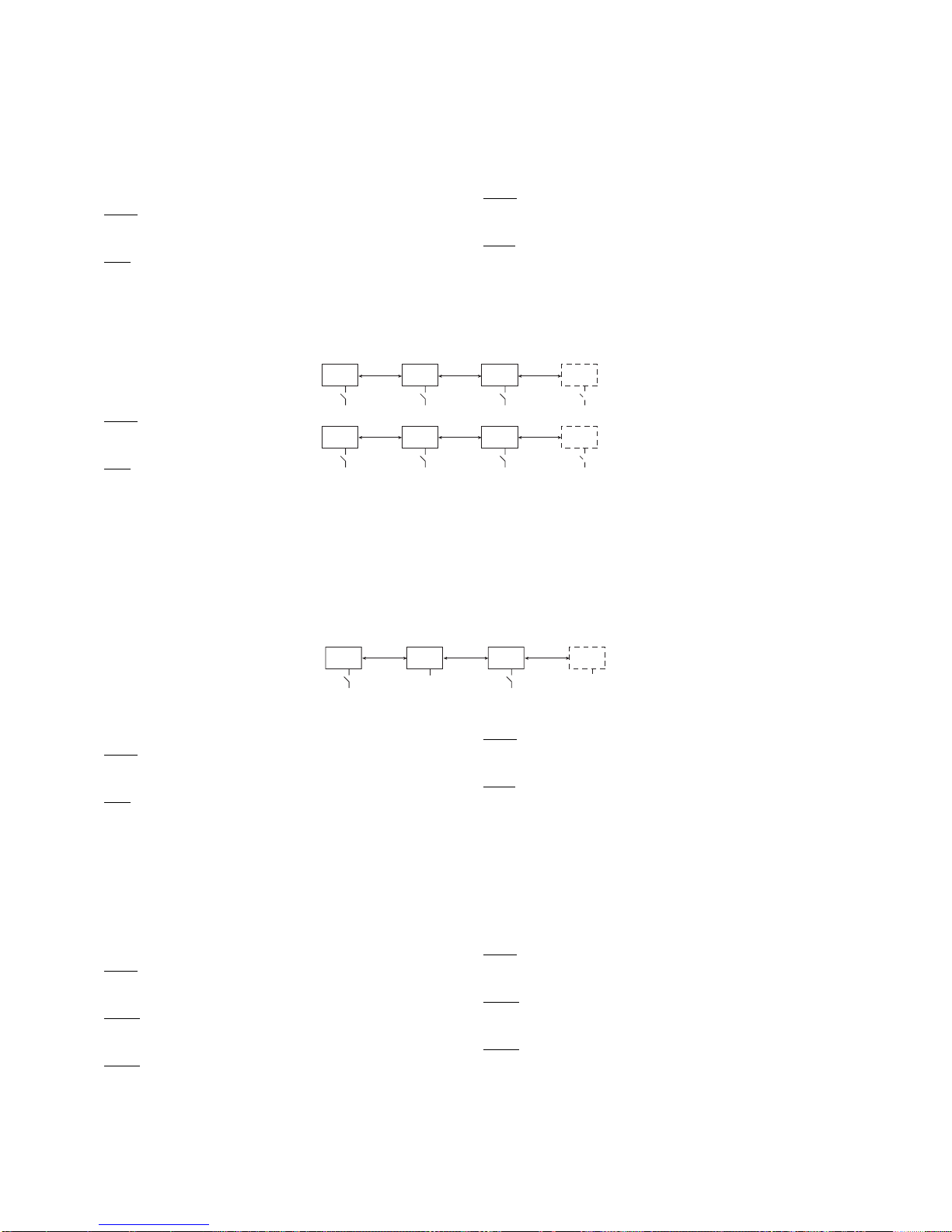
40
powerSplit manual - cod.+030220320 rel. 1.1 - 09/12/02
5.2 Esempi d’uso dell’ingresso digitale virtuale.
Lo stato dell’ingresso DIN 2 del Master può essere propagato via LAN
alle unità Slave, le quali possono condizionare il loro funzionamento sullo
stato di DIN 2 propagato, se opportunamente programmate.L’ingresso
fisico DIN 2 degli Slave viene disabilitato, mentre ne viene usata la
programmazione logica.Per fare in modo che le unità Slave siano
condizionate allo stato di DIN 2 del Master configurare il sistema nel
seguente modo:
Master
Ld = 1
A5 = funzione desiderata
Sla
ve
Ld = 1
A5 = UGUALE a quella del Master
Esempio pratico (Fig. 5.2.1):
Si immagini di avere un sistema
composto da una serie di banchi frigoriferi
dotati di tenda unica, programmando il
sistema nel seguente modo:
Master
Ld = 1 propagazione di DIN 2 attiva
A5 = 5 Switch porta
Slave
Ld = 1 abilitazione alla ricezione di DIN
2 del Master
A5 = 5 Switch porta
L’apertura dello Switch porta nel Master attiverà le funzioni: accensione
luce nel Master e negli Slave, commutazione automatica con Set Point
giorno nel Master e negli Slave.Alla chiusura si spegneranno le luci e
si otterrà il setpoint notte (locale ad ogni unità).
Esempio pratico (Fig. 5.2.2)
Questo esempio è esplicativo di una
funzionalità complementare a quella di
Fig.5.2.1.Si immagini, ora di avere un
sistema composto da una serie di banchi
frigoriferi dotati di tende separate, ognuna
dotata del proprio switch, programmando il
sistema nel seguente modo:
Master
Ld = 0 propagazione di DIN 2 disabilitata
A5 = 5 Switch porta
Sla
ve
Ld = 0 disabilitazione alla ricezione di DIN 2 del Master
A5 = 5 Switch porta
Ogni regolatore sarà autonomo sia per le luci che per il Set Point,
mentre il defrost sarà sincronizzato.Ma il sistema può essere
configurato anche in modo misto.
Si immagini di avere un sistema composto da una serie di banchi
frigoriferi dotati alcuni di tende separate, altri in comune.
Programmando il sistema nel seguente modo:
Master
Ld = 0 propagazione di DIN 2 abilitata
A5 = 5 Switch porta
Sla
ve 1
Ld = 1 abilitazione alla ricezione di DIN 2 del Master
A5 = 5 Switch porta
Sla
ve 2
Ld = 0 disabilitato alla ricezione di DIN 2 del Master
A5 = 5 Switch porta
Lo Slave 1 seguirà il Master mentre lo Slave 2 sarà autonomo, i defrost
saranno sincronizzati in ogni caso con il Master.
5.2 Examples on using the virtual digital input.
The status of input DIN 2 on the Master can be sent across the LAN,
and the Slave units can change their operation according to the status
of DIN 2 sent, if suitably programmed.The physical input DIN 2 on the
Slaves is disabled, however its programming logic is used.To control
the Slave units according to the status of DIN 2 on the Master, the
units need to be configured as follows:
Master
Ld = 1
A5 = desired function
Slaves
Ld = 1
A5 = EQUAL to the value on the Master
Practical example (Fig.5.2.1):
Imagine having a system made up of a
series of showcases with one curtain only.
The system should be programmed as follows:
Master
Ld = 1 propagation of DIN 2 enabled
A5 = 5 door Switch
Slaves
Ld = 1 enable the reception of DIN 2 from
the Master
A5 = 5 door Switch
The opening of the door Switch on the Master will activate the
following functions:switch on the light on the Master and the Slaves,
automatic switching to the day-time Set Point on the Master and on the
Slaves. When the switch is closed, the lights will turn off and the
night-time set point will be used (local for each unit).
Practical example (Fig.5.2.2):
This example is complementary to the
one shown in Fig.5.2.1. Imagine having a
system made up of a series of
showcases fitted with separate curtains,
each with their own switch. The system
should be programmed as follows:
Master
Ld = 0 propagation of DIN 2 disabled
A5 = 5 door switch
Sla
ves
Ld = 0 disable the reception of DIN 2 from the Master
A5 = 5 door switch
Each system will be independent regarding both the lights and the Set
Point, while the defrosts will be synchronised.However, the system can
also be configured in a mixed fashion.
Imagine a system consisting of a series of showcases, some fitted with
separate curtains, others in common.
Program the system as follows:
Master
Ld = 0 propagation of DIN 2 enabled
A5 = 5 door Switch
Sla
ve 1
Ld = 1 enable the reception of DIN 2 from the Master
A5 = 5 door Switch
Sla
ve 2
Ld = 0 disable the reception of DIN 2 from the Master
A5 = 5 door Switch
Slave 1 will follow the Master, while Slave 2 will be independent, the
defrost will in any case be synchronised with the Master.
MASTER
MASTER
SLAVE 1
SLAVE 1
SLAVE 2
SLAVE 2
SLAVE X
SLAVE X
Fig. 5.2.1
MASTER SLAVE 1 SLAVE 2 SLAVE X
Fig. 5.2.2
Page 45

41
powerSplit manual - cod.+030220320 rel. 1.1 - 09/12/02
6. Parametri:Tabella riassuntiva
Parametri e valori di default
Sigla Descrizione parametro Tipo Min. Max. U.M. DEF Note
PS password F 0 199 22 Valore Password da inserire per accedere a parametri
tipo C
/2 Stabilità misura globale C 1 15 flag 4 1= filtro valore medio basso, misura veloce
15= filtro valore medio alto, misura lenta
/4 Sonda vir tuale C 0 100 % 0 sonda virtuale tra sonda regolazione e sonda prodotto
0 = solo sonda regolazione S1;1...99 = media pesata S1 - S3
100 = solo sonda prodotto S3
/7 Visualizzazione sonda visualizzatore C 0 4 flag 0 Visualizzatore: impostazioni come per terminale (/ t)
/t Visualizzazione sonda ter minale C 0 4 flag 4 Terminale
0 = Non presente;1 =sonda ambiente (S1)
2 = sonda defrost (S2);3 = sonda prodotto (S3)
4 = sonda regolazione [virtuale] (pesata S1 S3)
/5 Selezione Centigradi/Fhren. C 0 1 flag 0 0 = gradi Centigradi, 1 = gradi Fahrenheit
/6 Autoscala C 0 1 flag 0 0 = visualizzazione al decimo, 1 = visualizzazione al grado
NB.questo parametro influenza solo la visualizzazione
dati e non la modifica degli stessi.
/8 Calibrazione - Sonda S3 C - 19.9 19.9 °C/°F 0 risoluzione 0,1 tra -19,9 +19,9 C°
/9 Defrost con sonda S3 C 0 1 flag 0 0 = con sonda defrost
1 = con sonda defrost + 2
o
evaporatore
/A Esitenza sonda defrost/sonda prodotto C 0 3 flag 2 0= defrost assente - sonda prodotto assente
1= defrost assente - sonda prodotto presente
2= defrost presente - sonda prodotto assente
3= defrost presente - sonda prodotto presente
/C Calibrazione sonda ambiente S 1 C -19.9 19.9 °C/°F 0 r isoluzione 0,1 tra -19,9 +19,9 C°
/d Calibrazione sonda defrost S 2 C - 19.9 19.9 °C/°F 0 risoluzione 0,1 tra -19,9 +19,9 C°
A0 Differenziale allarme e ventole C 0 19.9 °C/°F 0,2 Default 0,2 C° , risoluzione 0,1 tra -19,9 +19,9 C°
A4 Conf.Input dig. 1 C 0 9 flag 0 Vedere tabella A4 - A5
A5 Conf.Input dig. 2 C 0 9 flag 0 Vedere tabella A4 - A5
A7 Ritardo input allarme ritardato C 0 199 min 0 se A4 o A5=2, 0 = immediato
Ad Ritardo allarme temperatura C 0 199 min 120 0=immediato
AH Allarme alta temperatura (delta) F 0 199 °C/°F 0 NB.Valore di scostamento dal Set Point di LAVORO (normale
o notturno). Anche gli allarmi si spostano di conseguenza.
Risoluzione 0,1 C° sempre positivo
AL Allarme bassa temperatura (delta) F 0 199 °C/°F 0 NB. Come parametro AH
c0 Ritardo accens.compr.e ventole acc. strum. C 0 15 min. 0
c1 Tempo min.tra 2 accensioni compr. C 0 15 min. 0
c2 Tempo min.spegnimento compessore. C 0 15 min. 0
c3 Tempo min.funzionamento compressore C 0 15 min. 0
c4 Sicurezza relè (funz.Sicurezza) Duty Setting C 0 100 min. 0 0 = sempre OFF, 1..99 = min, 100 = sempre ON
c6 Tempo esclusione allarme dopo cc C 0 15 ore 2
cc Ciclo continuo C 0 15 ore 4
d0 Tipo sbrinamento C 0 3 flag 0 0= resistenza: finisce in temperatura e/o time out
1= gas caldo:finisce in temperatura e/o time out
2= resistenza:finisce per time out
3= gas caldo:finisce per time out
d2 Tipo comando defrost C 0 1 flag 0 0= solo star t, generico Slave
1= start + stop da rete, Slave di un Power Split
d4 Sbrinamento all'accensione strument. C 0 1 flag 0 0= no, 1= si
d5 Ritardo Sbrin. accensione o da input digit. C 0 199 min 0
d6 Visualizzazione durante sbrin. C 0 1 flag 1 0= no blocco vis.temperatura alternata a 'dF'
1= blocco display, visualizza l'ultima temperatura letta
d8 Tempo esclus.allarme dopo sbrinamento F 0 15 ore 1 vedere configurazione ingressi digitali.
o porta aperta NB.Se il ritardo viene impostato a zero e la por ta viene
lasciata aperta indefinitamente non viene emesso nessun
allarme.
d9 Priorità sbrinamento su prot. compressore C 0 1 flag 0 0= no, 1= si
dd Tempo gocciolamento dopo sbrinamento F 0 15 min 2
dI Intervallo tra sbrinamenti F 0 199 ore 8 0 = disabilitato
dP Durata max. sbrinamento/effettiva F 1 199 min 30 effettiva se d0=2 o 3 o LAN defrost
dt Temp.fine sbrinamento F -50.0 199 °C/°F 4,0 risoluzione 0,1 C°
F0 Gestione ventole C 0 1 flag 0 0= sempre accese escluse fasi specifiche F2, F3, Fd
1= termostatate con temp.evaporatore
F1 Temp.accensione ventole F -40.0 50.0 °C/°F 5,0 temperatura risoluzione 0,1 °C, valida se F0=1
F2 Ventole ferme con compressore fermo C 0 1 flag 1 0=no, 1=yes - solo con F0=0
F3 Ventole ferme in sbrinamento C 0 1 flag 1 0=no, 1=yes - con F0 = 0 e F0 = 1
Fd Fermo post gocciolamento F 0 15 min 1
H0 Indir izzo seriale C 1 199 1 0= Master 1..199 = Slave
Page 46

42
powerSplit manual - cod.+030220320 rel. 1.1 - 09/12/02
Sigla Descrizione parametro Tipo Min. Max. U.M. DEFAULT Note
Tab.1: Configurazione ingresso digitale (A4 e A5)
0= disabilitato
1= allarme esterno immediato n.chiuso, aperto= allarme
2= allarme esterno ritardato n. chiuso, aperto= allarme
3= abilitazione defrost da contatto esterno n. aperto= disabilitato
4= inizio sbrinamento da contatto esterno n. aperto
5= switch porta n.chiuso
6= ON/OFF remoto n. chiuso= ON
7= Switch notte n. aperto
8= duty setting da comando esterno n. chiuso
9= switch porta comp.ON n.chiuso
Tab.2: Configurazione uscite relè AUX1 e AUX2 (H1 e H2)
0 = uscita disabilitata
1 = uscita compressore
2 = uscita sbrinamento
3 = uscita ventole
4 = uscita allarme diretto
5 = uscita luce (default per H1)
6 = uscita ausiliaria (default per H2)
7 = uscita allarme invertito
Tab.3: Data giorno per evento di defrost
0 = disabilitato
1..7 = lunedì..domenica
8 = da lunedì a venerdì
9 = da sabato a domenica
10 = tutti i giorni
H1 AUX 1 funzione relè n. 4 C 0 7 5 Vedere tabella funzioni uscite AUX1 e AUX2
Utilizzo di Default LUCE
H2 AUX 2 funzione relè n. 5 C 0 7 6 Vedere tabella funzioni uscite AUX1 e AUX2
Utilizzo Default per ANTIAPPANNANTE
H3 disabilita tastiera C 0 1 0 0= abilitata, 1 = disabilitata
In Configurazione unità Master/Slave C 0 1 flag 0 0=Slave, 1=Master - per unità singole lasciare default (0)
L1 sensibilità sensore fotoresistivo C 0 2 flag 0 0= disabilitato, 1= bassa sensibilità, 2= alta sensibilità
Lt durata tempo luce accesa da sens. ore C 1 15 min 10
Lo abilita ON/OFF locale C 0 1 flag 0 1 = ON/OFF locale abilitato, 0 = ON/OFF locale disabilitato
LL abilita ON/OFF da rete C 0 1 flag 0 1= ON/OFF da rete abilitato, 0= ON/OFF da rete disabilitato
Ld Propagazione su LAN DIN 2 C 0 1 flag 0 Se Master: 0= non propaga stato DIN 2
1= propaga stato DIN 2
Se Slave: 0 = non usa lo stato propagato di DIN 2
1= usa lo stato propagato di DIN 2
r1 Set minimo consentito all'utente C -50.0 r2 °C/°F -50.0 risoluzione 0,1 C°
r2 Set massimo consentito all'utente C r1 19.99 °C/°F 90.0 risoluzione 0,1 C°
r3 Abilitazione segnalaz.Ed (time out defrost) C 0 1 flag 0
r4 Set Point notturno C -20 20 °C/°F 3,0 risoluzione 0,1 C°
r5 Abilitaz.monitoraggio temp. min./max. C 0 1 flag 0 0= no, 1= sì - Nota:transizione OFF/ON azzera lettura
r6 Regolazione notturna con sonda prodotto C 0 1 flag 0 0= disabilitato 1= abilitato
rd Differenziale regolatore (isteresi) F 0 19.9 °C/°F 2,0
rH Temp.max. rilevata durante <rt> F 0 0 °C/°F 0 r isoluzione 0.1 C°
rL Temp.min. rilevata durante <rt> F 0 0 °C/°F 0 risoluzione 0.1 C°
rt Intervallo effettivo rilevazione temp. F 0 0 ore 0
S8 velocità comunicazione seriale RS485 C 0 1 flag 1 0 = 9600 Baud, 1 = 19200 Baud
Sn Numero di slave C 0 5 flag 1 solo su unità Master 0= nessuna unità Slave collegata
su Slave o unità singole lasciare Default (=1)
St Set Point lavoro C r1 r2 °C/°F -10,0 risoluzione 0.1 C
°to rReset allarme HACCP - HA - HF C 0 1 flag 0 0 = allarme HACCP non presente
1 = allarme HACCP presente, si può resettare.
Variabile settata solo da allarme HACCP e resettata
esplicitamente o da tasto HACCP su terminale LARGE
*tu giorno sett. evento HA C 1 7 gg 0 Solo visualizzazione (range 1...7) Lunedi... Domenica
*th ora evento HA C 0 23 ore 0
*t* minuto evento HA C 0 59 min. 0
|tu giorno settimana evento HF C 1 7 gg 0 Solo visualizzazione (range 1..7 Lunedi... Domenica)
|th ora evento HA C 0 23 ore 0
|t* minuto evento HA C 0 59 min. 0
tr ritardo allarme HACCP C 0 199 min. 0 0 = disabilitato
¯T1 Evento defrost n. 1
o
giorno C 0 10 0 Data giorno per evento di defrost (Vedere tabella 3)
-T1 Evento defrost n. 1oora C 0 23 ore 0 Data ora per evento di defrost
_T1 Evento defrost n.1
o
minuto C 0 59 min 0 Data minuto per evento di defrost
...
¯Tn Evento defrost n. nogiorno C 0 10 0 Data giorno (Vedere tabella 3)
-Tn Evento defrost n. noora C 0 23 ore 0
_Tn Evento defrost n.n
o
minuto C 0 59 min 0
...
¯T6 Evento defrost n. 6ogiorno C 0 10 0 Data giorno (Vedere tabella 3)
-T6 Evento defrost n. 6
o
ora C 0 23 ore 0
_T6 Evento defrost n.6ominuto C 0 59 min 0
tM Minuto corrente orologio C 0 59 min 0
th Ora corrente orologio C 0 23 ore 0
td Giorno corrente della settimana C 1 7 gg 0
Page 47

43
powerSplit manual - cod.+030220320 rel. 1.1 - 09/12/02
6. Parameters - Summary Table
Parameters and DEFAULT values
Code Description Type Min. Max. UOM DEF Notes
PS password F 0 199 22 Password for access to type C parameters (value = 22)
/2 Overall measurement stability C 1 15 flag 4 1 = medium low filter value, fast measurement
15 = medium high filter value, slow measurement
/4 Vir tual probe C 0 100 % 0 virtual probe on control probe and product probe
0 = control probe S1 only;1...99 = weighted average S1 - S3
100 = product probe S3 only
/7 Display probe C 0 4 flag 0 Display: settings as for the terminal (/ t)
/t Terminal probe C 0 4 flag 4 Terminal: 0 = Not present;1= ambient probe (S1)
2 = defrost probe (S2); 3= product probe (S3)
4 = control probe [virtual] (weighted S1 S3)
/5 Centigrade/Fahrenheit selection C 0 1 flag 0 0 = degrees Centigrade, 1 = degrees Fahrenheit
/6 Scale C 0 1 flag 0 0 = display to the tenth,1 = display to the degree
NB this parameter only affects the display, and not the
modification of the data.
/8 Calibration probe S3 C -19.9 19.9 °C/°F 0 0.1 resolution between -19.9 +19.9 C°
/9 Defrost with probe S3 C 0 1 flag 0 0= with defrost probe;
1= with defrost probe + 2nd evaporator
/A Presence of defrost probe/product probe C 0 3 flag 0.2 0=defrost absent product probe absent
1=defrost absent product probe present
2=defrost present product probe absent
3=defrost present product probe present
/C Ambient probe calibration S 1 C - 19.9 19.9 °C/°F 0 0.1 resolution between -19.9 +19.9 C°
/d Defrost probe calibration S 2 C - 19.9 19.9 °C/°F 0 0.1 resolution between -19.9 +19.9 C°
A0 Alarm and fan differential C 0 19.9 °C/°F 2 Default 0.2°C, 0.1 resolution between -19.9 +19.9 C°
A4 Conf. digital input 1 C 0 9 flag 0 See Table A4 - A5
A5 Conf. digital input 2 C 0 9 flag 0 See Table A4 - A5
A7 Delayed alarm input delay C 0 199 mins 0 if A4 or A5=2;0 = immediate
Ad Temperature alarm delay C 0 199 mins 120 0=immediate
AH High temperature alarm (delta) F 0 199 °C/°F 0 NB Deviation from the Set Point (normal or night-time).
The alarms also shift as a consequence.
0.1°C resolution, always positive
AL Low temperature alarm (delta) F 0 199 °C/°F 0 NB: As for parameter AH
c0 Comp. fan start delay instrument ON C 0 15 mins. 0
c1 Min. time between 2 compressor starts C 0 15 mins. 0
c2 Min. compressor OFF time C 0 15 mins. 0
c3 Min. compressor ON time C 0 15 mins. 0
c4 Safety function Duty Setting C 0 100 mins. 0 0 = always OFF;1..99 = min; 100 = always ON
c6 Alar m bypass time after cc C 0 15 hours 2
cc Continuous cycle C 0 15 hours 4
d0 Type of defrost C 0 3 flag 0 0=electric heater: end by temperature and/or time out
1=hot gas:end by temperature and/or time out
2=electric heater: ends by time out;3=hot gas: ends by time out
d2 Type of defrost control C 0 1 flag 0 0=star t only, generic slave;
1=start+stop via network, PowerSplit slave
d4 Defrost at power up C 0 1 flag 0 0=no, 1=yes
d5 Defrost delay at ON or from dig.input C 0 199 mins 0
d6 Display during defrost. C 0 1 flag 1 0=display temp.alter nating with 'dF'
1=display OFF, displays last temperature read
d8 Alarm bypass time after defrost F 0 15 hours 1 see configuration of the digital inputs.
or door open NB:If the delay is set to zero and the door is left open indefinitely,
no alarm is signalled.
d9 Defrost priority over compr.protection C 0 1 flag 0 0=no, 1=yes
dd Dripping time after defrost F 0 15 mins 2
dI Inter val between defrosts F 0 199 hours 8 0 = disabled
dP Max/effective defrost duration F 1 199 mins 30 effective if d0=2 or 3 or LAN defrost
dt End defrost temp. F -50.0 199 °C/°F 4.0 0.1°C resolution
F0 Fan management C 0 1 flag 0 0=always on, except specific phases F2, F3, Fd
1=temp.control with evaporator temp.
F1 Fan ON temp. F -40.0 50.0 °C/°F 5.0 0.1°C temperature resolution, valid if F0=1
F2 Fans OFF with compressor OFF C 0 1 flag 1 0=n;1=yes only when F0=0
F3 Fans OFF in defrost C 0 1 flag 1 0=no;1=yes when F0 = 0 and F0 = 1
Fd Fans OFF in post-dripping F 0 15 mins 1
H0 Serial address C 1 199 1 0= master 1..199 = slave
H1 AUX 1 function relay no.4 C 0 7 5 See table of functions of the AUX1 and AUX2 outputs.
Default LIGHT
H2 AUX 2 function relay no.5 C 0 7 6 See table of functions of the AUX1 and AUX2 outputs
Default DEMIST
Page 48

44
powerSplit manual - cod.+030220320 rel. 1.1 - 09/12/02
Code Description Type Min. Max. UOM DEF Notes
H3 disable keypad C 0 1 0 0= enabled; 1 = disabled
In Unit Master/Slave configuration C 0 1 flag 0 0= Slave;
1= Master - for stand-alone units leave the default (0)
L1 Photocell sensitivity C 0 2 flag 0 0 = disabled; 1 = low sensitivity;2 = high sensitivity
Lt Light on time from sensor C 1 15 mins 10
Lo Enable local ON/OFF C 0 1 flag 0 1 = local on/off enabled; 0 = local on/off disabled
LL Enable network ON/OFF C 0 1 flag 0 1= network on/off enabled; 0= network on/off disabled
Ld Propagation of DIN 2 on LAN C 0 1 flag 0 If Master: 0= do not propagate status of DIN 2
1= propagate status of DIN 2
If Slave: 0 = do not use the propagated status of DIN 2
1= use the propagated status of DIN 2
r1 Minimum Set allowed to user C -50.0 r2 °C/°F -50.0 0.1°C resolution
r2 Maximum Set allowed to user C r1 19.99 °C/°F 90.0 0.1°C resolution
r3 Signal enabling Ed (defrost time-out) C 0 1 flag 0
r4 Night-time Set Point C -20 20 °C/°F 3.0 0.1°C resolution
r5 Enable min.max. temp.monitoring C 0 1 flag 0 0=no;1=yes Note: switching OFF/ON resets the reading
r6 Night-time control with product probe C 0 1 flag 0 0=disabled; 1=enabled
rd Control differential (hysteresis) F 0 19.9 °C/°F 2.0
rH Max. temp.measured during <rt> F 0 0 °C/°F 0 0.1°C resolution
rL Min.temp. measured during <rt> F 0 0 °C/°F 0 0.1°C resolution
rt Effective temp.measurement interval F 0 0 hours 0
S8 RS485 serial communication speed C 0 1 flag 1 0 = 9600 Baud, 1 = 19200 Baud
Sn Number of slaves C 0 5 flag 1 only on Master unit 0= no Slaves connected
on Slave or stand-alone unit leave Default (=1)
St Temperature Set Point C r1 r2 °C/°F -10.0 0.1°C resolution
to Reset HACCP alarms - HA - HF C 0 1 flag 0 0 = HACCP alarm not present
1 = HACCP alarm present, can be reset.
Variable only for HACCP alarms, and reset either explicitly
or from HACCP button on LARGE terminal
*tu weekday HA event C 1 7 days 0 Display only (range 1..7, Monday... Sunday)
*th hours HA event C 0 23 hours 0
*t* minutes HA event C 0 59 mins. 0
|tu weekday HF event C 1 7 days 0 Display only ( range 1..7, Monday... Sunday)
|th hours HF event C 0 23 hours 0
|t* minutes HF event C 0 59 mins. 0
tr HACCP alarm delay C 0 199 mins. 0 0 = disabled
¯T1 Defrost event No.1
st
day C 0 10 0 Date day for defrost event (see Table 3)
-T1 Defrost event No.1sthours C 0 23 hours 0 Date hours for defrost event
_T1 Defrost event No.1
st
minutes C 0 59 mins 0 Date minutes for defrost event
...
¯Tn Defrost event No.nndday C 0 10 0 Date day (see Table 3)
-Tn Defrost event No.nndhours C 0 23 hours 0
_Tn Defrost event No.n
nd
minutes C 0 59 mins 0
...
¯T6 Defrost event No.6ndday C 0 10 0 Date day (see Table 3)
-T6 Defrost event No.6
nd
hours C 0 23 hours 0
_T6 Defrost event No.6
nd
minutes C 0 59 mins 0
tM Current minutes C 0 59 mins 0
th Current hours C 0 23 hours 0
td Current weekday C 1 7 days 0
TABLE 1: Digital input configuration (A4 and A5)
0= disabled
1= immediate external alarm nor m. closed, open = alarm
2= delayed external alarm norm.closed, open = alar m
4= start defrost from external contact norm. open
5= door switch norm. closed
7= night switch norm.open
6= remote on/off norm. closed =ON
3= enable defrost from external contact norm. open= disabled
8= duty setting from external control norm. closed
9= door switch comp.ON norm. closed
TABLE 2: Configuration of relay outputs AUX1 and AUX2 (H1 - H2)
0 = disabled output
1 = compressor output
2 = defrost output
3 = fan output
4 = alarm output
5 = light output (default for H1)
6 = aux output (default for H2)
7 = alarm inv.output
TABLE 3: Date day for defrost event:
0 = disabled
1..7 = Monday ...Sunday
8 = from Monday to Friday
9 = Saturday to Sunday
10 = all days
Page 49

45
powerSplit manual - cod.+030220320 rel. 1.1 - 09/12/02
7. ALLARMI e ricerca guasti
In caso di allarme premendo il tasto si tacita la cicalina e si
diseccità il relè di allarme, mentre il codice d’errore visualizzato viene
cancellato solo quando rientra la causa che lo ha generato.
7.1 Codici di allarme e segnalazioni
L’allar me rE verrà visualizzato in abbinamento ad un allarme sonda, in
quanto indica che la sonda di regolazione è guasta, e può essere S1,
S3 od una combinazione di esse.
7. ALARMS and troubleshooting
In the event of an alarm Pressing the button silences the buzzer
and de-energises the alarm relay, while the error code displayed is
deleted only when the causes of the alarm are no longer present.
7.1 Alarm codes and signals
The rE alarm will be displayed together with a probe alarm, in that
indicates that the control probe is faulty;the control probe may be
probe S1, S3 or a combination of both.
Cod. Allarme Buzzer / Rele allarme Descrizione Modelli predisposti
E1 non attivi errore sonda 1 TUTTI
E2 non attivi errore sonda 2 TUTTI
E3 non attivi errore sonda 3 TUTTI
rE ATTIVI errore sonda regolazione TUTTI
IA ATTIVI allarme esterno immediato TUTTI, se configurato allarme esterno
Id ATTIVI Duty Setting da contatto esterno TUTTI, se configurato Duty Settting
dA ATTIVI allarme esterno r itardato TUTTI, se configurato allarme ritardato
EA non attivi allarme E2P/orologio TUTTI
(NB.nelle unità senza RTC ovviamente solo per E2P)
HI ATTIVI allarme alta temperatura TUTTI
LO ATTIVI allarme bassa temperatura TUTTI
HA ATTIVI allarme HACCP mancanza alimentaz. solo unità con RTC configurate come MASTER
HF ATTIVI allarme HACCP ecceduto tempo solo unità con RTC configurate come MASTER
Ed non attivi sbrinamento finito per time out TUTTI
nX (X=1..5) ATTIVI slave X in allarme solo unità con RTC configurate come MASTER
uX (X=1..5) ATTIVI slave X non comunicante solo unità con RTC configurate come MASTER
tC non attivi orologio resettato solo unità con RTC
/- non attivi porta aper ta da troppo tempo TUTTI, se configurato un ingresso porta
cn ..... mancanza com.con PSB TUTTI
E0 ..... mancanza com. con PSB TUTTI
dF non attivi defrost TUTTI
Nota:
Lo stato del relè di allarme si riferisce ad unità che ne abbiano almeno uno configurato in tal modo.
Nelle unità predisposte il relè di allarme risulta normalmente eccitato.
Alarm code Buzzer/Alarm relay Description Models featured
E1 not active probe 1 error ALL
E2 not active probe 2 error ALL
E3 not active probe 3 error ALL
rE ACTIVE control probe error ALL
IA ACTIVE immediate external alarm ALL, if external alarm configured
Id ACTIVE Duty Setting from external contact ALL, if Duty Setting configured
dA ACTIVE delayed external alarm ALL, if delayed alarm configured
EA not active E2P/clock alarm ALL
NB.in units without RTC obviously for E2P only
HI ACTIVE high temperature alarm ALL
LO ACTIVE low temperature alarm ALL
HA ACTIVE HACCP alarm, time exceeded units with RTC configured as MASTER only
HF ACTIVE HACCP alarm power failure units with RTC configured as MASTER only
Ed not active defrost ended by time out ALL
nX (X=1..5) ACTIVE slave X alarm units with RTC configured as MASTER only
uX (X=1..5) ACTIVE slave X not communicating units with RTC configured as MASTER only
tC not active reset clock units with RTC only
/- not active door open for too long ALL, if door input configured
cn ..... no comp.with PSB ALL
E0 ..... no comp. with PSB ALL
dF not active defrost ALL
Note:
The state of the alarm relay refers to units that have at least one relay configured in such fashion.
When fitted, the alarm relay is normally energised.
Page 50

46
powerSplit manual - cod.+030220320 rel. 1.1 - 09/12/02
7.2 Note sugli allarmi
Gli allarmi possono essere soppressi o ritardati in alcune situazioni:
- Durante il duty setting gli allarmi di temperatura sono soppressi
- Dopo un duty setting, ciclo continuo e defrost, gli allarmi sono
ritarati, rispettivamente, di 5 minuti, c6 e d8 minuti.
7.3 Ricerca ed eliminazione dei problemi
Il Master segnala che uno o più Slave non comunicano.
Controllare che:
- tutti gli Slave abbiano il parametro Sn impostato correttamente,
ovvero con valori tra 1 e 5, e che ogni unità abbia indirizzo diverso H0.
- che il parametro S8 sia impostato a 1 in tutte le unità, Master
compreso.
Il Master segnala che lo Slave X è in errore ma il relè d’allarme di
questo non risulta eccitato.
Connettere un terminale allo Slave X e controllare il codice d’errore,
alcuni errori es.EA, tC non eccitano il relè d’allarme.
Il terminale è collegato e indica “- - -“, la tastiera non risponde.
Il terminale è disabilitato: tenendo premuto il tasto SET, apparirà PS,
selezionare, quindi, il parametro /t e programmarlo ≠0.Confermare
premendo il tasto SET per 5 secondi.
Il terminale è collegato e indica la temperatura ma la tastiera non
risponde.
La tastiera potrebbe essere disabilitata:controllare la programmazione
del parametro H3, se = 0 è disabilitata.
Il terminale è collegato, e indica “Cn”
Il terminale ha comunicato per un periodo con il PSB poi ha perso la
comunicazione:controllare i cavi di collegamento e le connessioni.
Il terminale è collegato e indica “E0”
Il terminale non ha mai comunicato con il PSB: controllare i cavi di
collegamento e le connessioni.
Il terminale mod. PST00LR200 è connesso ma non comunica con
il PSB.
Controllare che il baud rate impostato tramite dip-switch sul terminale
sia 4800 Baud.
Il visualizzatore è collegato e non si accende.
Probabilmente il visualizzatore non si è resettato:spegnere e
riaccendere il sistema, aspettando almeno un decina di secondi tra le
due operazioni.
Il visualizzatore ogni 10 secondi circa si spegne e poi si riaccende.
Se il sistema è privo del terminale, controllare il parametro /t e
impostarlo a 0.
Viceversa, controllare il funzionamento del terminale, probabilmente
non funziona regolarmente.
Il sistema non visualizza i decimi di grado.
Controllare le impostazioni del parametro /6.
Ricordarsi che con il terminale Small, superati i -9.9 gradi, il punto
decimale viene automaticamente soppresso, visualizzando –10.
7.2 Notes on the alarms
The alarms may be inhibited or delayed in some cases:
- During duty setting, the temperature alarms are inhibited
- After duty setting, continuous cycle and defrost, the alarms are
delayed, respectively, by 5 minutes, c6 and d8 minutes.
7.3 T roubleshooting
The Master signals that one or more Slaves are not communicating.
Check that:
- all Slaves have parameter Sn set correctly, that is, to values between
1 and 5, and that each unit has address different H0.
- parameter S8 is set to 1 on all the units, including the Master.
The Master signals an error on Slave X but the alarm relay on
Slave X is not energised.
Connect a terminal to Slave X and check the error code, some errors
e.g.EA, tC do not energise the alarm relay.
The terminal is connected and indicates “- - -“, the keypad does
not respond.
The terminal is disabled:press and hold SET, the PS will appear, then
select the parameter /t and set it ≠0.Confir m by pressing SET for 5
seconds.
The terminal is connected and indicates the temperature, but the
keypad does not respond.
The keypad may be disabled:check the setting of parameter H3, if = 0
the keypad is disabled.
The terminal is connected, and indicates “Cn”
The terminal has communicated for a period with the PSB, and then
lost communication:check the cables and the connections.
The terminal is connected and indicates “E0”
The terminal has never communicated with the PSB:check the cables
and the connections.
The terminal model PST00LR200 is connected but does not
communicate with the PSB.
Check that the baud rate set using the dip-switches on the terminal is
4800 Baud.
The display is connected and but does not turn on.
The display has probably not been reset:turn the system off, wait at
least ten seconds and then turn it on again.
Each 10 seconds or so the display switches off and then on again.
If the system is not fitted with a terminal, check parameter /t and set it
to 0.
Vice-versa, check the operation of the terminal, it is probably not
working correctly.
The system does not displays the tenths of a degree.
Check the settings of parameter /6.
Remember that with the Small terminal, beyond -9.9 degrees the
decimal point is automatically inhibited and -10 will be displayed.
Page 51

47
powerSplit manual - cod.+030220320 rel. 1.1 - 09/12/02
Il defrost in una unità autonoma termina sempre per tempo
massimo.
Controllare che:
1. il parametro d0 sia programmato a 0 o 1
2. il parametro /9 sia programmato in maniera opportuna, se =1 deve
essere presente un secondo evaporatore.
Il sistema attende che la temperatura di fine defrost sia stata
raggiunta anche su questo evaporatore.
Il defrost in una unità Slave termina sempre per tempo massimo.
Controllare che il parametro d0 nel Master sia programmato a 0 o 1, in
caso contrario il Master non invia il comando di fine defrost.
Perché compare sempre la segnalazione Ed.
Ci possono essere alcune cause:
- se è stato impostato il parametro d0=2 o 3 ovvero defrost a tempo,
ed il parametro r3=1 si avrà la segnalazione Ed ad ogni defrost.
In questo caso programmare r3=0.
- se è stato impostato un defrost in temperatura d0=0 o 1 e non esiste
la sonda di defrost, la funzione terminerà per timeout e, quindi,
si avrà Ed.
Ho configurato A4=4 (Switch Porta) ma il sistema reagisce come
se la porta fosse sempre aperta.
Controllare di non aver programmato A5=4, nel qual caso il sistema
userà come ingresso porta il secondo ingresso digitale.
Se tento di programmare /4≠0 il parametro torna a 0 da solo.
Il parametro /A è stato programmato a 0 o a 3, in questo caso il
parametro /4 è automaticamente impostato a 0.
Ho configurato A4/A5=2 (allarme esterno ritardato) ma l’allarme
scatta subito.
Controllare lo stato dell’ingresso digitale e verificare se A7≠0.
Ho configurato A4/A5=3, e dopo la conclusione di un defrost ne
comincia subito un altro.
Controllare che il contatto collegato all’ingresso digitale sia aperto alla
fine del defrost, altrimenti il sistema interpreterà la chiusura come una
ulteriore richiesta di defrost.
Ho impostato c1, c2,c3, c4 = 0 ma la richiesta di accensione del
compressore non è istantanea ma parte dopo alcuni secondi.
Questo funzionamento è regolare per le macchine con il parametro H0
programmato tra 1 e 5, il meccanismo (vedi manuale) serve per
impedire accensioni contemporanee dei compressori dei PSB in una
rete locale.
Ho un PSB inserito in una rete di supervisione, facendo partire un
defrost da comando di supervisione il suo defrost termina sempre
per timeout.
Controllare il parametro d2 e impostarlo a 0.
Il sistema di supervisione non riesce a collegarsi con un PSB.
Controllare che:
- il parametro In sia impostato a 1, ovvero come Slave, in caso
contrario il PSB comincia a inviare messaggi in rete alla ricerca di
PSB Slave, alterando in questo modo anche le comunicazioni del
sistema di supervisione.
- controllare il parametro S8 e assicurarsi che il baud rate impostato
sia identico.
La luce si comporta in modo strano.
Esistono diversi modi di comandare la luce, inoltre questi modi
possono essere attivati contemporaneamente.
Per evitare problemi bisogna essere certi che esista un unico modo
attivo di gestire la luce.
Riepilogando i parametri/azioni coinvolti sono:
1. se l’unità è Slave ed il Master comanda la luce, nello Slave devono
essere inibite tutte le funzioni di gestione della luce.
The defrost on a stand-alone unit always ends after the maximum
time.
Check that :
1. parameter d0 is set to 0 or 1
2. parameter /9 is suitably set, if =1 a second evaporator must be
present.
The system waits for the end defrost temperature to be reached on this
evaporator too.
The defrost on a Slave unit always ends after the maximum time.
Check that parameter d0 on the Master is set to 0 or 1, otherwise the
Master will not send the end defrost command.
The signal Ed always appears.
There are a couple of possible causes:
- if parameter d0=2 or 3, that is, timed defrost, and parameter r3=1,
there will be an Ed signal at each defrost.
In this case set r3=0.
- if temperature defrost is set, d0=0 or 1, and there is no defrost probe,
the function will end by timeout, and Ed will be displayed.
The unit is set with A4=4 (Door Switch), but the system reacts as
if the door were always open.
Check that A5=4, in which case the system uses the second digital
input as a door input.
Trying to set /4≠0,the parameter returns to 0 on its own.
Parameter /A has been set to 0 or 3, in this case parameter /4 is
automatically set to 0.
The unit is set with A4/A5=2 (delayed external alarm) but the alarm
goes off immediately.
Check the status of the digital input and check that A7≠0.
The unit is set with A4/A5=3, and after the end of a defrost
another starts immediately.
Check that the contact connected to the digital input is open at the end
of defrost, otherwise the system will interpret the closing of the contact
as a further defrost request.
The unit is set with c1, c2,c3, c4 = 0 yet the compressor start
request is not instant, rather there is a delay of a few seconds.
This operation is normal on machines where parameter H0 is set
between 1 and 5;this mechanism (see the manual) is used to prevent
simultaneous starts of compressors in a local PSB network.
The PSB is connected to a supervisor network, yet when star ting
a defrost from the supervisor ends the defrost by timeout.
Check parameter d2 and set it to 0.
The supervisor system cannot connect to the PSB.
Check that:
- parameter In is set to 1, that is, Slave, otherwise the PSB starts to
send messages on network to find the PSB Slaves, and thus alters
the communication mode of the supervisor system.
- check parameter S8, and make sure that the set baud rate is
identical.
The light behaves strangely.
There are different ways of controlling the light, which can be activated
at the same time.
To prevent problems, make sure only one of the modes is active.
In summary, the parameters/actions involved are:
1. if the unit is a Slave and the Master controls the light, all the light
control functions on the Slave must be inhibited.
Page 52

48
powerSplit manual - cod.+030220320 rel. 1.1 - 09/12/02
2. se si usa la fotocellula non usare la porta e viceversa.
3. se si usa la porta l’altro ingresso digitale non deve essere configurato
uguale.
4. attenzione all’uso dell’ingresso propagato.
Il tasto luce sul terminale non comanda la luce, o si accende
brevemente e poi si spegne/accende.
La luce può essere pilotata anche attraverso alcuni automatismi che
bypassano la tastiera (riferirsi al manuale), in ogni caso controllare :
- se il parametro L1 è ≠0, il sistema è controllato da fotocellula.
- se i parametri A4/A5 sono programmati a 4 o 5, il sistema è
controllato dalla porta o dalla tenda.
- se il sistema è Slave di un PSB, lo stato della luce è imposto dal
Master.
- se il sistema è in una rete di supervisione verificare che non imponga
lo stato della luce.
Il tasto di ON/OFF sul terminale non agisce sul controllo / Il
Master non comanda lo stato di ON/OFF negli Slave.
Riferirsi al manuale per la spiegazione della gestione e configurazione
dello stato di ON/OFF.
Controllare i parametri Lo e LL.
Se Lo è = 0 l’ON/OFF da tastiera è disabilitato, se LL=0 l’ON/OFF da
rete è disabilitato,
Se Lo=1 e LL=1 l’ON/OFF da tastiera è disabilitato.
Ho configurato su una unità stand alone l’ingresso digitale n.2 su
switch notte, ma lo switch non provoca nessuna azione.
Controllare la configurazione del parametro Ld, se = 1 l’ingresso fisico
è disabilitato e viene usato quello virtuale.
Non riesco ad attivare il ciclo continuo in uno Slave di un banco
canalizzato, composto da un Master e da X Slave:il sistema esce
subito dal ciclo.
Il ciclo continuo è sotto il controllo del Master, se questo è in ciclo
continuo anche gli Slave andranno in ciclo continuo ed alla conclusione
sul Master saranno forzati ad uscire.
Non riesco ad attivare/disattivare il relè ausiliario,tramite il
comando da terminale, in uno Slave di un banco canalizzato,
composto da un Master e da X Slave.
Anche il relè ausiliario è sotto il controllo del Master e ne segue lo
stato, azionando il comando AUX dal terminale del Master si
condizionerà anche il funzionamento dello Slave.
Se scollego uno Slave il Master non lo comunica subito.
Il Master aspetta circa 20 secondi prima di comunicare che uno Slave
è effettivamente fuori linea.
Nel caso ce ne fosse più di uno, il primo viene comunicato dopo 20
secondi i successivi immediatamente.
Ho variato dei parametri ma, dopo aver spento e riacceso il
sistema, non trovo più le modifiche.
Le variazioni dei parametri vengono memorizzate dopo circa
30 secondi dall’ultima richiesta, quindi, dopo aver effettuato delle
modifiche attendere circa 30 secondi per essere certi che la variazione
sia stata effettivamente memorizzata.
Ho acceso la luce e dopo poco è caduta l’alimentazione di rete, al
ripristino la luce non si è riaccesa (vale anche per l’AUX).
Come descritto nel punto precedente le variazioni vengono
memorizzate dopo circa 30 secondi dall’ultima richiesta,
quindi, l’alimentazione è caduta prima di 30 secondi la luce non verrà
ripristinata.
2. if using the photocell, do not use the door switch, and vice-versa.
3. if using the door, the other digital input must not be configured in the
same way.
4. check the use of the propagated input.
The light button on the terminal does not control the light,or it
switches briefly and then switches off/on.
The light can also be controlled automatically, bypassing the keypad
(refer to the manual);in any case, check:
- if parameter L1 is ≠0, the system is controlled by the photocell.
- if parameters A4/A5 are set to 4 or 5, the system is controlled by the
door or the curtain switch.
- if the system is a PSB Slave, the status of the light is set by the
Master.
- if the system is in a supervisor network, check that the system does
not impose the status of the light.
The ON/OFF button on the terminal has no effect / the Master
does not control the ON/OFF of the Slaves.
Refer to the manual for the explanation of the management and
configuration of the ON/OFF status.
Check parameters Lo and LL.
If Lo is = 0, the ON/OFF button on the keypad is disabled, if LL=0,
the network ON/OFF is disabled,
If Lo=1 and LL=1, the ON/OFF button on the keypad is disabled.
A stand alone unit is set with digital input no.2 used for a night
switch,yet the switch has no effect.
Check the configuration of parameter Ld, if = 1 the physical input is
disabled and is used as a virtual input.
The continuous cycle does not start on a Slave in a multiplexed
system made up of a Master and X Slaves,the system
immediately exits the cycle.
The continuous cycle is controlled by the Master;if the Master is in
continuous cycle, the Slaves too will start the continuous cycle and are
forced to exit at the end by the Master.
The auxiliary relay cannot be activated/deactivated,using the
command on the terminal, on a Slave in a multiplexed system
made up of a Master and X Slaves.
The auxiliary relay, and consequently its status, is also controlled by
the Master.Operating the AUX command on the Master terminal will
also send the command to the Slaves.
On disconnecting a Slave the Master does not communicate the
event immediately.
The Master waits around 20 seconds before signalling that a Slave is
effectively off-line.
In the case where more than one Slave is disconnected, the first is
communicated after 20 seconds, and others immediately after.
The parameters have been modified,but after having switched the
system off and on again the changes are no longer present.
The parameters are saved after around 30 seconds from the last
request, therefore after having made the modifications wait around 30
seconds to be certain that the changes have effectively been saved.
The light is switched on and shortly after there is a power failure;
when power returns the light does not come on (the same is also
true for the AUX).
As described in the previous point, the changes are saved after around
30 seconds from the last request, and therefore in the event of power
failures within 30 seconds, the status of the light will not be restored.
Page 53

49
powerSplit manual - cod.+030220320 rel. 1.1 - 09/12/02
8. Caratteristiche tecniche controlli PSB
Alimentazione 230 Vac +10/-15 % 50-60Hz
Potenza Nominale 5VA assorbiti a 230Vac
Ingressi sonda 3 ingressi per sonde NTC Lung.max 30 m per
Tipo di sonda - precisione NTC Std Carel 10K 25 ˚C - +/- 1˚C tutti gli ingressi
Intervalli di rilevazione -50T90 ( -50 +90 ˚C, -58 + 195 ˚F) risoluzione 0,1 ˚C
Ingressi digitali Ingressi per contatto pulito non optoisolati
Contatto aperto-chiuso 10 Vdc - 10 mA Typ.
Connessione Seriale LAN Connessione a due cavi AWG22-24 lung.max. 10 m Schermo opzionale
Uscite Relè:tipo di azione e Azione tipo 1B (microdisconn.) EN60730 100.000 op. UL 250 Vac 30.000 op.
disconnessione e Nr.di cicli Nota: Relè in scambio caratterizzato per NO o NC
di manovra
Compressore 2HP (COMPR) Contatto NO 10(10) A-250Vac EN60730-1 12 A 10 FLA 60 LRA
Carico Motore 2HP max. 10A max 100000 op UL 250Vac
Defrost 16 A (DEFR) Contatto SPDT 14(2) A-250 Vac (NO) , 2(2) NC 14 A Res. (NO), 2 A(NC)
Ventilatore 10 A (FAN) Contatto NO 4(2) A-250 Vac 4 A 2 FLA 12 LRA
Allarme (*) 10 A (ALARM) Contatto SPDT 4(2) A-250 Vac 4 A 2 FLA 12 LRA
Aux 1 - Luce 16 A (AUX 1) Contatto NO 10(10) A-250 Vac
Fluorescent Lamp 1000 VA-110uF max. 15000 op. 12 A 10 FLA 60 LRA
Aux 2 - (*) Antiap.10 A (AUX2) Contatto NO 4(2) A-250 Vac 4 A 2 FLA 12 LRA
Connessioni Corrente max.continua per tutti i relè attivati 25 A
totali (10+2+2+2+5+4) A
Morsetti alimentazione Morsetti a vite 30 A max 250 Vac cavi 4 mm2sezione max. Per alimentazione carichi e controllo
Faston alimentaz.carichi e FASTON 6,3 mm per cavi da 2,5mm
2
sezione consigliata Connessioni di appoggio per
messa a terra (minimo 1,5 mm2) corrente max.15A alimentazione carichi L, N , TERRA
Morsetti per segnali I/O Morsetti a vite cavi da 0,5 a 1,5 mm
2
Montaggio A parete (retroquadro) mediante distanziali plastici o metallici
Terminale / Visualizzatore Connessione seriale a 4 fili lunghezza max 10 m: alimentazione fornita dal controllo
• Terminale opzionale PST Small o PST Large 9 Vdc 150 mA o 24-35 Vdc 1,5 W max
• Visualizzatore opzionale PST00VR100
Condizioni funzionamento -10T50 ˚C umidità non condensante
Condizioni immagazzinamento -20T70 ˚C umidità non condensante
Classificazione secondo la protezione Classe II per incor poramento adeguato Trasformatore in doppio isolamento e
contro le scosse elettriche distanze relè per isolamento rinforzato
Ambiente (tipo inquinamento) Normale
PTI dei materiali di isolamento 250V
Periodo di soll. delle parti isolanti Lungo
Categoria di res.al calore e al fuoco Categor ia D (funzionamento senza sor veglianza ).
Immunità contro le sovratensioni Categoria 1
Classe e struttura software Classe A
Orologio RTC Gestione DD :HH :MM :SS giorno settimana (1-7) Presente solo su alcuni modelli
precisione +/- 20ppm ( +/-10 min/anno)
Mantenimento dati RTC Con batteria ricaricabile litio 7 mAh (eq. a circa 6 mesi a piena carica) Ricarica completa in circa 20 ore
(*):Relè Allarme e Aux2 non presente in versione 4relè
Page 54

50
powerSplit manual - cod.+030220320 rel. 1.1 - 09/12/02
8.Technical specifications,PSB controllers
Power supply 230Vac +10/-15 % 50-60Hz
Rated power 5VA at 230Vac
Probe inputs 3 inputs for NTC probes Max.length 30 metres for
Type of probe - precision Std Carel NTC 10K 25 C - +/- 1˚C all the inputs
Range of measurement -50T90 (-50 +90 ˚C, -58 + 195 ˚F) 0.1˚C resolution
Digital inputs Inputs for non-optically-isolated free contacts
Open-closed contact 10Vdc - 10mA typ.
LAN serial connection Two-wire connection, AWG22-24, max.length 10 m Optional shield
Relay outputs:type of action and Type 1B action (microswitching) EN60730 100,000 cycles
disconnection, and no.of operating Note: Changeover relay for NO or NC only
cycles UL250Vac 30,000 cycles
Compressor 2HP (COMPR) NO contact 10(10)A-250Vac EN60730-1 12A 10FLA 60LRA
Motor load 2HP max.10A max 100,000 cycles UL250Vac
Defrost 16A (DEFR) SPDT contact 14(2)A-250Vac (NO), 2(2) NC 14A Res. (NO), 2A(NC)
Fan 10A (FAN) NO contact 4(2)A-250Vac 4A 2FLA 12LRA
Alarm (*) 10A (ALARM) SPDT contact 4(2)A-250Vac 4A 2FLA 12LRA
Aux 1 - Light 16A (AUX1) NO contact 10(10)A-250Vac
Fluorescent lamp 1000VA-110uF max.15,000 cycles 12A 10FLA 60LRA
Aux 2 -(*) Demist 10A (AUX2) NO contact 4(2)A-250Vac 4A 2FLA 12LRA
Connections: Max. direct current for all the activated relays,
25A total (10+2+2+2+5+4) A
Power supply ter minals Screw terminals 30A max 250Vac max.4 mm
2
cross-section For power supply to loads and
controller
Power supply fastons for loads and earth 6.3 mm FASTONS for recommended cross-section of 2.5 mm
2
Support connection for power supply
(minimum 1.5 mm2) max.current 15A to loads, L, N, EARTH
Terminals for I/O signals Screw terminals for wires with cross-section from 0.5 to 1.5 mm
2
Mounting Wall (rear of the panel), using plastic or metal spacers
Terminal / Display 4-wire ser ial connection, max. length 10m: power supply from the controller,
• optional PST Small or PST Large terminal 9Vdc 150mA or 24-35Vdc 1.5W max
• optional PST00VR100 display
Operating conditions -10T50˚C non-condensing humidity
Storage conditions -20T70˚C non-condensing humidity
Classification according to protection Class II for suitable integration Transformer with double insulation and
against electric shock relay distance for reinforced insulation
Environmental pollution Normal
PTI of insulating materials 250V
Period of stress across insulating parts Long
Category of res.to heat and fire Category D (operation without sur veillance )
Immunity against voltage surges Category 1
Software class and structure Class A
RTC clock Management of DD:HH:MM:SS weekday (1-7) Present on some models only
precision +/- 20ppm (+/-10 min/year)
RTC data storage With rechargeable 7 mAh lithium battery (equal to around 6 Complete recharge in around
months at full charge). 20 hours.
(*):Alarm and Aux2 relay not present in the 4-relay version
Page 55
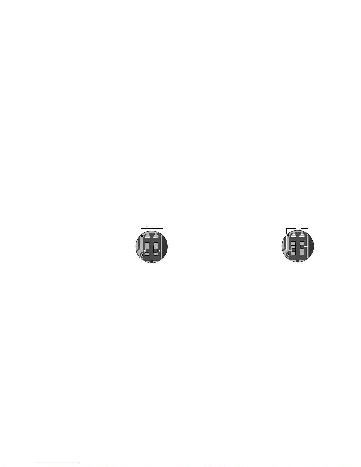
51
powerSplit manual - cod.+030220320 rel. 1.1 - 09/12/02
9. Accessori
9.1 Chiave copia parametri
La chiave è un accessorio che permette la duplicazione della
configurazione di uno strumento e il successivo trasferimento su
controlli con lo stesso codice.
Tale chiave è diversa da quella per PJ in quanto è un accessorio non
specializzato per un singolo controllo, ma utilizzabile su molti futuri
controlli CAREL oltre ai due attuali.
La gestione delle funzioni è realizzata all' interno di ogni singolo
controllo, quindi, si descrivono solo le funzioni base sempre presenti,
per le altre si deve fare riferimento al manuale di ogni controllo.
La chiave si collega al connettore (AMP 4 pin) previsto nei controlli
compatibili (Power-Split, MGE al momento).
Il funzionamento è previsto di standard con controlli non alimentati,
ma anche con alimentazione presente, se specificato nelle note di
utilizzo del singolo controllo.
Le funzioni previste sono due e si selezionano mediante i due
dip-switch presenti, accessibili togliendo il coperchio batteria:
a) Caricamento nella chiave dei parametri di un controllo (UPLOAD)
b) Copia dalla chiave verso uno o piu' controlli (DOWNLOAD).
- PJOPZKEY00 è da utilizzare SOLO per strumenti PJ...
- PSOPZKEY è da utilizzare SOLO per controlli compatibili.
9.2 Copia e scarico parametri
Le operazioni da seguire per le funzioni di UPLOAD e/o DOWNLOAD
sono le seguenti, cambiando solo le impostazioni dei dip-switch sulla
chiave:
• chiudere lo sportellino della chiave e inserirla nel connettore del
controllo
• Premere il tasto e controllare la segnalazione del LED:rosso per
qualche secondo, quindi verde indica la corretta conclusione della
operazione.
Segnalazioni diverse o con lampeggi indicano che si sono verificati dei
problemi:controllare la tabella relativa.
• A conclusione dell’operazione rilasciare il tasto, dopo qualche
secondo il LED si spegne.
• Scollegare la chiave dal controllo.
9. Accessories
9.1 Parameter copy key
The key is an accessory that allows the configuration to copied from an
instrument and then later transferred to controllers with the same code.
It differs from the key for the PJ, in that it is not a specialised accessory
for one single controller, but rather can be used on many future Carel
controllers, as well as two current models.
The functions are managed internally by each single controller, and
thus the functions described here are the basic operations only;for the
others, please refer to the specific manual for each controller.
The key is connected to the connector (4 pin AMP) on the Power-Split
compatible controllers, currently the MGE.
The devices is normally operated with the controllers off, yet the
power supply may be connected if specified in the instructions for the
controller in question.
There are two functions, selected using the two dip-switches that are
accessed by removing the battery cover:
a) Copy the parameters from a controller to the key (UPLOAD)
b) Copy the parameter from the key to one or more controls
(DOWNLOAD).
- PJOPZKEY00 can ONLY be used with PJ instruments.
- PSOPZKEY can ONLY be used for compatible controllers.
9.2 Copy and download parameters
The following operations refer to both the UPLOAD and/or
DOWNLOAD functions, changing only the settings of the dip-switch on
the key:
• close the hatch of the key and insert it into the connector on the
controller
• Press the button and check the signal on the LED:red for a few
seconds, then green, indicating the correct completion of the
operation.
Different signals or the LED flashing indicate that a problem has
occurred:check the table below.
• At the end of the operation, release the button;after a few seconds
the LED goes off.
• Disconnect the key from the controller.
1
OFF
OFF
ON
2
1
OFF
OFF
2
UPLOAD:impostazione dip-switch:
UPLOAD:dip-switch setting:
DOWNLOAD:impostazione dip-switch:
DOWNLOAD:dip-switch setting:
Page 56

52
powerSplit manual - cod.+030220320 rel. 1.1 - 09/12/02
9.3 Segnalazione errori
9.4 Caratteristiche tecniche Chiave PSOPZKEY
Alimentazione - Utilizzare tre elementi 1,5 V 190 mA
(D357H Duracell o equivalenti)
- Corrente massima fornita su
connettore 50 mA max
(5 Vdc batterie cariche)
Condizioni di funzionamento 0T50 ˚C UR < 90% non condensante
Condiz.di immagazzinamento -20T70 ˚C UR < 90% non condensante
Dimensioni Plastico 42x105x18
9.3 Error signals
9.4 Technical specifications, PSOPZKEY key
Power supply - Three 1.5V 190mA batteries
(D357H Duracell or equivalent)
- Maximum current supplied at the
connector 50mA
(charged 5Vdc batteries)
Operating conditions 0T50 ˚C RH <90% non-condensing
Storage conditions -20T70 ˚C RH <90% non-condensing
Dimensions Plastic 42x105x18
Segnalazione LED Errore Significato e soluzione
LED rosso lampeggiante Batteria scarica inizio copia Batteria scarica o copia non eseguita: sostiture le batterie e riprovare.
LED verde lampeggiante Batteria scarica fine copia Operazione di copia eseguita correttamente, alla fine dell’operazione
la tensione di batteria risulta bassa: consigliabile la sostituzione delle
batterie.
Lampeggio alternato LED rosso/verde Strumento non compatibile Il setup parametri non puo’ essere copiato in quanto il modello del
controllo collegato non è compatibile.
Tale errore è associato solo alla funzione DOWNLOAD:verificare il
codice del controllo ed eseguire la copia solo su codici compatibili.
LED rosso e verde accesi Errori di copia Errore nei dati copiati: ripetere l'operazione, se il problema persiste
verificare la chiave (batterie, connessioni).
LED rosso acceso stabile Errori di trasferimento dati L' operazione di copia non si è conclusa per errori gravi di trasferimento
o copia dei dati:ripetere la operazione, se il problema persiste
verificare la chiave (batterie, connessioni).
LED spenti Batterie scollegate Verificare lo stato delle batterie:controllo carica e/o inserimento corretto
Error Signal LED Meaning and solution
Red LED flashing Flat battery at star t copy Battery is flat or copy not performed: change the batteries and try again.
Green LED flashing Flat battery at end copy Copy operation performed correctly, low battery voltage at the end of the
operation, the batteries should be changed.
Alternating flash, red/green LED Instrument not compatible The parameters cannot be copied, as the model of controller connected
is not compatible.
This error is only applicable for the DOWNLOAD function:check the
code of the controller and only copy to compatible codes.
Red and green LEDs ON Copy errors Error in the data copied: repeat the operation, if the problem persists,
check the key (batteries, connections).
Red LED ON steady Data transfer errors The copy operation was not completed due to serious errors in
transferring or copying the data:repeat the operation, if the problem
persists check the key (batteries, connections).
LED OFF Batteries disconnected The status of the batter ies. Check the charge and correct insertion
Page 57

Page 58

notes / note:
Page 59

Page 60

Cod. +030220320 rel. 1.1 - 09/12/02
Agenzia / Agency:
CAREL S.p.A.
Via dell’Industria, 11 - 35020 Brugine - Padova (Italy)
Tel.(+39) 049.9716611 - Fax (+39) 049.9716600
e-mail:[email protected] - www.carel.com
 Loading...