


Integrated Control Solutions & Energy Savings
pCO5+
NO POWER
& SIGNAL
CABLES
TOGETHER
READ CAREFULLY IN THE TEXT!
Programmable Controller
User manual


3
ENG
pCO5plus +0300020EN rel. 1.2 - 07.11.2013
IMPORTANT
CAREL bases the development of its products on decades of experience in
HVAC, on the continuous investments in technological innovations to products,
procedures and strict quality processes with in-circuit and functional testing on
100% of its products, and on the most innovative production technology available
on the market. CAREL and its subsidiaries nonetheless cannot guarantee that all
the aspects of the product and the software included with the product respond
to the requirements of the fi nal application, despite the product being developed
according to start-of-the-art techniques.
The customer (manufacturer, developer or installer of the fi nal equipment) accepts
all liability and risk relating to the confi guration of the product in order to reach
the expected results in relation to the specifi c fi nal installation and/or equipment.
CAREL may, based on specifi c agreements, act as a consultant for the positive
commissioning of the fi nal unit/application, however in no case does it accept
liability for the correct operation of the fi nal equipment/system.
The CAREL product is a state-of-the-art product, whose operation is specifi ed in the
technical documentation supplied with the product or can be downloaded, even
prior to purchase, from the website www.CAREL.com.
Each CAREL product, in relation to its advanced level of technology, requires setup
/ confi guration / programming / commissioning to be able to operate in the best
possible way for the specifi c application. The failure to complete such operations,
which are required/indicated in the user manual, may cause the fi nal product to
malfunction; CAREL accepts no liability in such cases.
Only qualifi ed personnel may install or carry out technical service on the product.
The customer must only use the product in the manner described in the
documentation relating to the product.
In addition to observing any further warnings described in this manual, the
following warnings must be heeded for all CAREL products:
• Prevent the electronic circuits from getting wet. Rain, humidity and all
types of liquids or condensate contain corrosive minerals that may damage
the electronic circuits. In any case, the product should be used or stored
in environments that comply with the temperature and humidity limits
specifi ed in the manual.
• Do not install the device in particularly hot environments. Too high
temperatures may reduce the life of electronic devices, damage them and
deform or melt the plastic parts. In any case, the product should be used
or stored in environments that comply with the temperature and humidity
limits specifi ed in the manual.
• Do not attempt to open the device in any way other than described in the
manual.
• Do not drop, hit or shake the device, as the internal circuits and mechanisms
may be irreparably damaged.
• Do not use corrosive chemicals, solvents or aggressive detergents to clean
the device.
• Do not use the product for applications other than those specifi ed in the
technical manual.
All of the above suggestions likewise apply to the controllers, serial boards,
programming keys or any other accessory in the CAREL product portfolio.
CAREL adopts a policy of continual development. Consequently, CAREL reserves
the right to make changes and improvements to any product described in this
document without prior warning.
The technical specifi cations shown in the manual may be changed without prior
warning.
The liability of CAREL in relation to its products is specifi ed in the CAREL general
contract conditions, available on the website www.CAREL.com and/or by specifi c
agreements with customers; specifi cally, to the extent where allowed by applicable
legislation, in no case will CAREL, its employees or subsidiaries be liable for any
lost earnings or sales, losses of data and information, costs of replacement
goods or services, damage to things or people, downtime or any direct, indirect,
incidental, actual, punitive, exemplary, special or consequential damage of any
kind whatsoever, whether contractual, extra-contractual or due to negligence, or
any other liabilities deriving from the installation, use or impossibility to use the
product, even if CAREL or its subsidiaries are warned of the possibility of such
damage.
DISPOSAL
INFORMATION FOR USERS ON THE CORRECT HANDLING OF WASTE
ELECTRICAL AND ELECTRONIC EQUIPMENT (WEEE)
In reference to European Union directive 2002/96/EC issued on 27 January 2003
and the related national legislation, please note that:
• WEEE cannot be disposed of as municipal waste and such waste must be
collected and disposed of separately;
• the public or private waste collection systems defi ned by local legislation must
be used. In addition, the equipment can be returned to the distributor at the
end of its working life when buying new equipment;
• the equipment may contain hazardous substances: the improper use or
incorrect disposal of such may have negative eff ects on human health and on
the environment;
• the symbol (crossed-out wheeled bin) shown on the product or on the
packaging and on the instruction sheet indicates that the equipment has
been introduced onto the market after 13 August 2005 and that it must be
disposed of separately;
• in the event of illegal disposal of electrical and electronic waste, the penalties
are specifi ed by local waste disposal legislation.
Warranty on the materials: 2 years (from the date of production, excluding
consumables).
Approval: the quality and safety of CAREL INDUSTRIES Hqs products are
guaranteed by the ISO 9001 certifi ed design and production system.
WARNING: separate as much as possible the probe and digital input signal
cables from the cables carrying inductive loads and power cables to avoid
possible electromagnetic disturbance.
Never run power cables (including the electrical panel wiring) and signal
cables in the same conduits.
NO POWER
& SIGNAL
CABLES
TOGETHER
READ CAREFULLY IN THE TEXT!

4
ENG
pCO5plus +0300020EN rel. 1.2 - 07.11.2013

5
ENG
pCO5plus +0300020EN rel. 1.2 - 07.11.2013
Content
1. INTRODUCTION 7
1.1 Programmability .................................................................................................7
1.2 Functional layout .................................................................................................8
1.3 Terminals..................................................................................................................9
1.4 BMS port expansion cards .............................................................................9
1.5 Fieldbus port expansions cards ............................................................... 10
1.6 External modules ..............................................................................................11
2. DESIGN 12
2.1 pCO5+ Design ....................................................................................................12
3. COMMUNICATION PORTS 13
3.1 Serial ports ............................................................................................................ 13
3.2 Port J26 confi guration ................................................................................... 14
3.3 Controller network connections.............................................................14
4. INSTALLATION 15
4.1 Mounting on DIN rail and dimensions ...............................................15
4.2 Installation ............................................................................................................ 15
4.3 Preliminary operations ..................................................................................16
4.4 Serial network electrical connections .................................................16
4.5 Connecting the terminal .............................................................................18
4.6 Input/output labels .........................................................................................19
4.7 I/O table .................................................................................................................20
4.8 Small and Medium pCO5+: connecting terminals .....................21
4.9 Large and Extralarge pCO5+: connecting terminals .................. 22
4.10 pCO5+ with built-in driver: connecting terminals ......................23
4.11 pCOE: connecting terminals .....................................................................23
4.12 pCO5+ terminals description ...................................................................24
5. INPUT/OUTPUT CONNECTIONS 26
5.1 Power supply ...................................................................................................... 26
5.2 Universal inputs/outputs .............................................................................26
5.3 Digital inputs .......................................................................................................29
5.4 Optically-isolated analogue outputs ...................................................31
5.5 Connecting the electronic valve ............................................................33
5.6 Digital outputs ................................................................................................... 34
5.7 Solid state relay (SSR) digital outputs .................................................34
5.8 General connection diagram .................................................................... 35
6. STARTUP 36
6.1 Switch-on .............................................................................................................. 36
6.2 Private and shared terminals .....................................................................36
6.3 Setting the controller’s address ...............................................................36
6.4 Setting the terminal’s address and connecting the
controller to the terminal ............................................................................ 37
6.5 Uploading software ........................................................................................ 38
6.6 Checking the software installed and other information .........39
7. APPLICATION DIAGRAMS 41
7.1 Devices that can be connected to the pCO5+ .............................44
8. TECHNICAL SPECIFICATIONS 46
8.1 pCO5+ Technical Specifi cations ..............................................................46
8.2 Conformity to standards .............................................................................. 50
8.3 Models ....................................................................................................................50
8.4 Connectors ...........................................................................................................50
9. APPENDIX 51
9.1 Smart Key: operating instructions .........................................................51
9.2 pCO Manager: operating instructions ................................................52
9.3 Pendrive: operating instructions ............................................................54
9.4 Confi guring pCOWeb/pCOnet from a system screen ..............58

6
ENG
pCO5plus +0300020EN rel. 1.2 - 07.11.2013

7
ENG
pCO5plus +0300020EN rel. 1.2 - 07.11.2013
1. INTRODUCTION
The pCO5+ is a microprocessor-based, programmable electronic
controller that is fully compatible (hardware and software) with the pCO
Sistema family of devices, which includes programmable controllers, user
terminals, gateways, communication devices and remote management
devices. These devices represent a powerful control system that can
be easily interfaced with most Building Management Systems (BMS)
available on the market.
The pCO5+ controller has been developed by CAREL to provide solutions
to a host of applications in air-conditioning, refrigeration and HVAC/R in
general. It is highly fl exible and can be used to make special products on
customer specifi cations.
In a pLAN network (pCO Local Area Network) the pCO5+ can be connected
to input/output expansion cards (e.g. pCOe), to other pCO5+ controllers,
to all the controllers of the pCO Sistema family and to the terminals of the
pGD range. Up to 32 devices (controllers and terminals) can be connected
together, allowing highly effi cient sharing of information. Each device in
the pLAN network can exchange digital or analogue data with all the
others, depending on the application program used.
Compared to pCO3 controllers, pCO5+ units are equipped with two extra
built-in RS485 serial ports – one for the Fieldbus and one for supervision/
telemaintenance purposes (BMS).
Each Fieldbus serial port, whether built into the controller or installed via
an optional card, can be connected to controlled fi eld devices such as
valve and damper actuators and external drivers (e.g. drivers for electronic
expansion valves, EVD Evolution).
Each BMS serial port, whether built into the controller or installed via
an optional card, can be connected to fi eld-level, automation-level
or management-level standard bus systems, such as Konnex®, LON®,
BACnet™, etc.
The Medium range includes controller versions with one or two built-in
drivers for electronic expansion valves. The Ultracap module (accessory)
can be used as an emergency power supply for valve drivers, and allows
shutting the valves completely in case of power failures (alternating
current).
Main features
• the same controller can be connected to up to 3 PGD terminals;
• the program and parameters are saved permanently in a non-volatile
memory (fl ash memory), preventing data loss in case of power failures
(without requiring a backup battery);
• 32-bit microprocessor controllers with 5 or 9 MB storage capacity
ensure high performance in terms of speed and memory space;
• allows connecting up to 32 devices to pLAN networks consisting
of a series of pCO5+ controllers and terminals. Each controller can
exchange data with the other controllers at high speed without
requiring additional hardware;
• external or built-in terminal with display and LED-button keypad; can
be used for uploading software and commissioning;
• fast upload/download of controller software using a “Smart Key(*)” or
any pendrive (provided the controller is equipped with the relative
port);
• universal inputs/outputs confi gurable via an application program for
connecting active and passive probes, digital inputs, analogue and
PWM outputs. This extends the possibilities of confi guring inputs/
outputs without having to install a larger controller;
• allows using the 1Tool software (installable on a personal computer)
for creating and customising application programs, performing
simulations, supervising operations and setting up pLAN networks;
• allows uploading application software to the controller using the pCO
Manager program, available free of charge at http://ksa.carel.com;
• many dedicated programs available for controlling a variety of HVAC/R
applications;
• allows developing new application programs according to customer
specifi cations;
• wide range of models distinguished by:
- microprocessor storage capacity: 5 or 9 MB;
- size (Small, Medium, Large, Extralarge), for maximum fl exibility
depending on the application;
- solid state relay (SSR) digital outputs (24/230 V);
- NO or NC relay outputs;
- USB ports;
- optically-isolated/non-optically-isolated built-in serial ports;
- built-in display.
• various kinds of connectors (spring, screw, etc.).
(*) function available from Smart Key fi rmware version 4.0.
Main features of terminal
Thanks to the capabilities of the application software, while the unit is
normally working the user terminal can be used to:
• edit the main parameters;
• receive acoustic alerts (from buzzer) and visual alerts (on display) of any
alarms triggered;
• view active functions and measured quantities displayed by LED
indicators.
1.1 Programmability
The programmable controllers of the pCO family can be programmed
using the 1Tool development software, which off ers the following
advantages:
• transferability of software. Applications developed for the pCO can be
quickly and easily transferred between diff erent hardware platforms by
simply modifying the inputs and outputs;
• rapid development of custom programs at competitive costs;
• reliability guaranteed by the use of standard routines, tested in the lab
and in the fi eld.
In addition, using 1Tool provides customers with maximum confi dentiality
and ample self-management when developing new programs on their
own. Using the same hardware for diff erent applications enhances
standardization, with the clear advantage of being able to perform incircuit, functional and burn-in tests on all products, thereby ensuring a
high level of reliability in general and in terms of individual electronic
components.
Applications
When provided with a dedicated application program, the same
controller can be used to control equipment of diff erent kinds:
• chillers and heat pumps;
• roof-top units;
• air-conditioners;
• small/medium-sized air handling units (on request);
• refrigerated counters (on request and to specifi cations);
• cold rooms (on request and to specifi cations);
• curing rooms;
• compressor racks;
• universal stage controllers.
8
ENG
pCO5plus +0300020EN rel. 1.2 - 07.11.2013
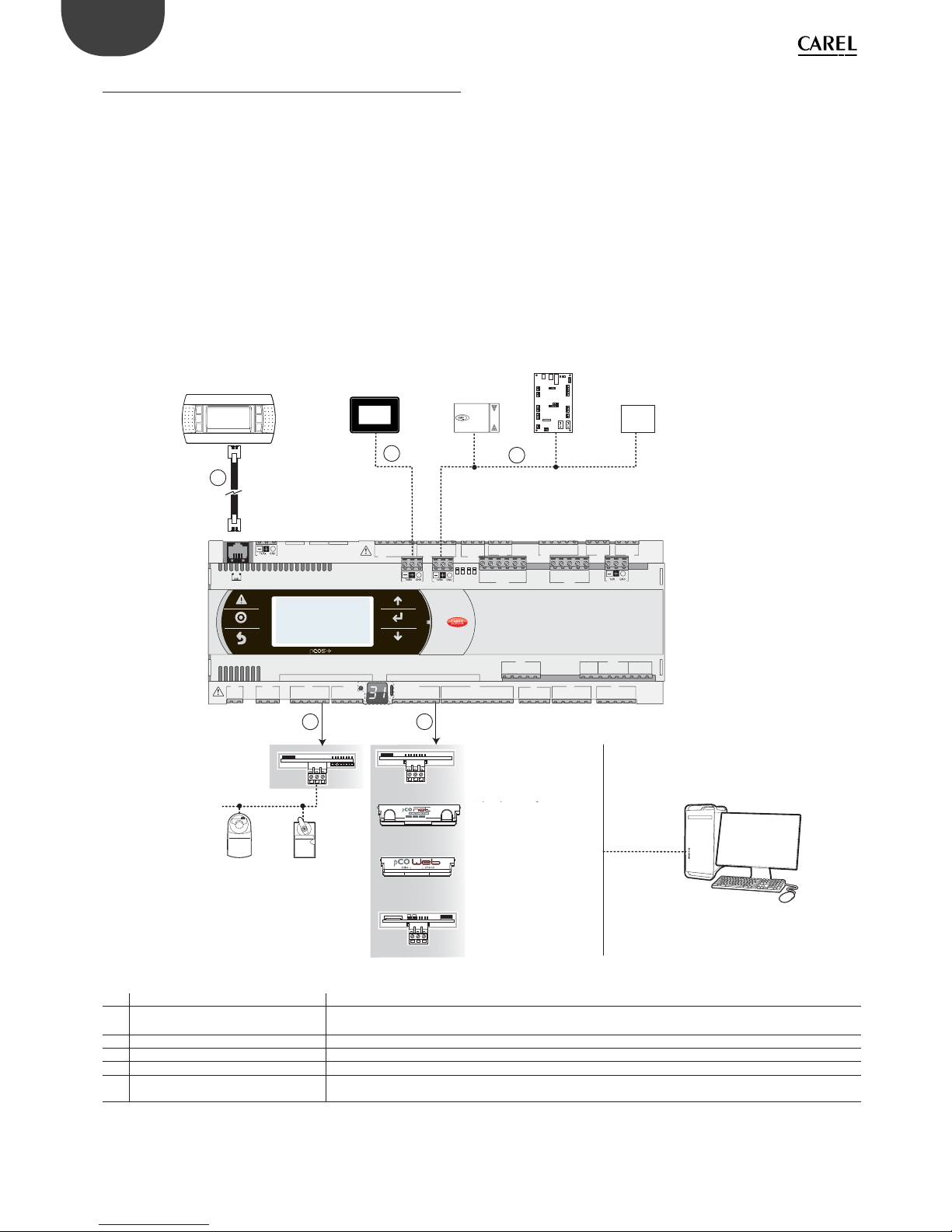
1.2 Functional layout
The fi gure below shows the functional layout of an air handling
unit. Damper actuators and valve actuators are fi eld devices that
communicate through Fieldbus 1 (ref. C). Fieldbus 2 (ref. E) is the medium
through which the serial probes communicate the values measured,
and through which the humidifi er control board and the fans exchange
data and receive setpoints from the controller. The built-in terminal and
the remote terminal, which communicate via pLAN (ref. A), are used for
installing the application program and for commissioning the system.
The PGD touchscreen terminal, intuitive and simple to use, can be used
while the unit is normally working to set switch-on and switch-off times,
to enter the main parameters, to perform other advanced functions of
the application program and to view any alarms triggered. In this case the
data is communicated through the BMS2 serial port (ref. D). The system
can be connected to a supervision system (Konnex®, LON®, BACnet™, etc.)
after installing the relative BMS1 expansion card (ref. B).
BELIMO
Scheda seriale RS485
Scheda interfaccia
LonWorks®
Scheda interfaccia
BACnet™ RS485
Sch. interfaccia
Ethernet™ /BACnet™
Servocontrollo
della serranda
BELIMO
Valvola di
servocontrollo
MP -BUS
Scheda MP-BUS
584SRsutats
GNX RS485
+ –
P1 P2 P3
BACnet™ MS/TP
FieldBus 1
BMS 1
J1
J24 J2 J3
J4
J5 J7
J8
J20
J21
J14
J10
J13J12
J22
J16 J1
7
J18
J15
J6
J19
FieldBus card
BM S card
J23 FBus2
J11 pLAN
J25 BMS2
J26 FBus2
43 21
Sonde seriali
Terminale PGD
touch screen
Terminale
Scheda controllo
umidificatori
Dispositivo
terze parti
FAN
FieldBus 2
D
E
BMS2
A
pLAN
C
B
Fig. 1.a
Ref. Serial port/Connectors Connection to:
A pLAN/J10, J11
up to 3 terminals
up to 32 devices in a pLAN network (pCO controllers, EVD Evolution valve drivers, terminals)
B BMS 1 Serial Card a building automation system, after installing the relative BMS card (see par. 1.4)
C FieldBus 1 Serial Card sensors, actuators, etc., on a Fieldbus, after installing the relative card (see par. 1.5)
D BMS 2 / J25* pGD Touch terminals, GPRS connection modules (built-in card)
E
Fieldbus 2/J26 (and J23 on Large and
Extralarge versions)
sensors, actuators, etc., on a Fieldbus (built-in card)
(*) available on P+5... models; not available on P+3... models; see par. 8.3.
Terminal
PGD touchscreen
terminal
Serial probes
Humidifi er control
board
Device
MP-BUS card
Servo-control
valve
Damper servo-
control
RS485 serial card
BACnetTM RS485
interface card
EthernetTM/BACnetTM
interface card
LonWorks interface
card*

9
ENG
pCO5plus +0300020EN rel. 1.2 - 07.11.2013
1.3 Terminals
Note: All instruction sheets can be downloaded from www.carel.
com in the “Documentation” section.
Code Description Notes
PGDT04000F***
(tech. leafl et code
+050001475)
pGD Touch 4.3” user
terminal
The pGD Touch 4.3” graphics terminal belongs to the family of touchscreen terminals,
designed to simplify and make more intuitive the interfacing of users with the controllers
of the pCO Sistema family. The electronic technology applied and the new 65,000-colour
display allows the terminal to handle high-quality images and advanced functions, providing an excellent aesthetic performance. In addition, the touchscreen panel facilitates
man-machine interaction, making it easier to navigate through the various screens.
PGDT07000F***
(tech. leafl et code
+050001490)
pGD Touch 7” user
terminal
See description of pGD Touch 4.3” user terminal.
PGDE000*
(tech. leafl et code
+050001450)
Graphics terminal
Allows complete graphics management through the use of icons (defi ned during the
development of the application software) and managing international fonts in two sizes:
5x7 and 11x15 pixels. The application software resides only on the pCO controller; the
terminal requires no additional software for operation. Accessories for installation:
• telephone connection cable, code S90CONN00*;
• TCONN6J000 shunt card (instr. sheet code +050002895).
PGD1000I00
(tech. leafl et code
+050001055)
Graphics terminal
(panel installation)
This model can be installed on the panel. Its graphics properties are identical to those of
the PGDE000 terminal*. Accessories for installation:
• telephone connection cable, code S90CONN00*;
• TCONN6J000 shunt card (instructions sheet code +050002895).
AT*
(tech. leafl et code
+0500016IE/
+0500017IE)
th-TUNE, terminal for
panel or wall instal-
lation
Allows the user to adjust the temperature and humidity in residential environments.
th-Tune is compatible with the main wall-boxes found in many countries (Italy, U.S.,
Germany, China).
1.4 BMS port expansion cards
Code Description Notes
PCOS004850
(tech. leafl et code
+050003237)
BMS RS485 serial
card
Can be installed on all controllers of the pCO family (except pCOB); allows direct interfacing with an RS485 network, max. baud rate 19200. The card ensures the controller’s
optical isolation from the RS485 serial network.
PCO10W0WB0
(tech. leafl et code
+050003238)
Ethernet - pCOweb
interface card
Can be installed on all controllers of the pCO family (except pCOB); allows connecting
the controller to a 10 Mbps Ethernet network and provides the following functions:
• access to controller data (network variables and parameters) through an Internet
browser (e.g. Internet Explorer™) installed on a PC and connected to the network
via TCP/IP to pCOWeb;
• connection to a supervisor network running the protocols indicated in the
instructions sheet.
PCO10W0BA0
(tech. leafl et code
+050000930)
BACnet MS/TP pCOnet interface
card
Allows connecting the controller to a BACnet MS/TP (Master/Slave Token pass) network. The RS485 connection is optically isolated from the controller.
10
ENG
pCO5plus +0300020EN rel. 1.2 - 07.11.2013
PCO10000F0
(tech. leafl et code
+050004045)
LonWorks® interface
card
Allows connecting to a LonWorks® TP/FT 10 network. The program resides in the fl ash
memory located in the socket, and can be programmed directly via the LonWorks®
network using network installation and maintenance tools such as LonMaker™.
Information on how to program the card is available in the relative manual, code
+030221960.
PCOS00KXB0
(tech. leafl et code
+050000770)
Konnex interface
card
Allows connecting to a network set up according to the Konnex® standard. Two
versions available: for BMS port and Fieldbus port.
PCOS00HBB0
(tech. leafl et code
+050000162)
CAN-bus serial card Allows connecting to CANbus networks, specifi cally to e-drofan fan coil
controllers, thanks to the capacities of the e-dronic system. This simplifi es plant
operation, optimizing comfort, enhancing synergies between controllers and
reducing operating costs. Two versions available: for BMS port and for Fieldbus
port.
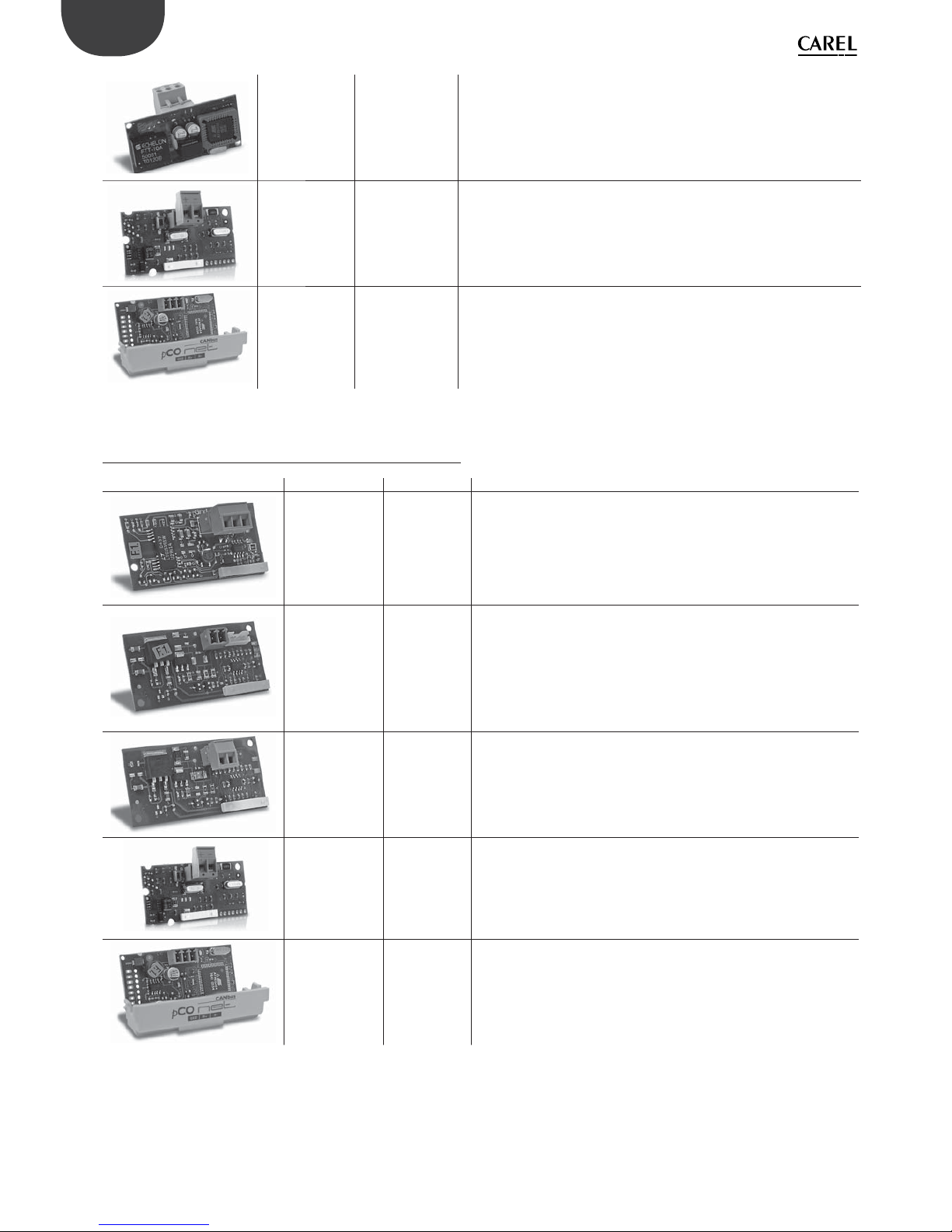
1.5 Fieldbus port expansions cards
Code Description Notes
PCO100FD10
(tech. leafl et code
+050003270)
RS485 serial card
Allows connecting to an RS485 network (through an electrically isolated interface).
The controller consequently acts as a MASTER (i.e. supervisor), therefore other controllers or devices can be connected as SLAVES. Up to 64 devices can be connected.
PCO100TLN0
(tech. leafl et Code
+050003270)
tLAN and PST
serial card
Allows connecting to a tLAN network through two separate connectors. The fi rst
is used to connect the controller to a tLAN network. Using this connection and a
suitably confi gured application in TLAN MASTER mode, the controller can interact
with the I/O expansion cards (tLAN version - PCOE00TLN0) or with other controllers
provided with a tLAN connection, confi gured in tLAN SLAVE mode.
Up to 5 devices can be connected. The second connector is used to connect to a
PST terminal. Both connections require using a shielded cable having a maximum
length of 10 m.
Attention: Do not use both connectors at the same time
PCO100MPB0
(tech. leafl et code
+050003270)
MP-BUS card
Allows connecting to an MP-Bus network consisting of devices (sensors, actuators)
set up according to the Belimo standard. Up to 8 actuators can be connected at
the same time, at a maximum distance of 30 m. See the specifi c documentation
provided by Belimo (www.belimo.ch).
PCOS00KXF0
(tech. leafl et code
+050000770)
Konnex interface
card
See description of PCOS00KXB0 serial card (previous paragraph).
PCOS00HBF0
(tech. leafl et code
+050000162)
CAN-bus serial
card
See description of CAN-bus PCOS00HBB0 serial card (previous paragraph).

11
ENG
pCO5plus +0300020EN rel. 1.2 - 07.11.2013
1.6 External modules
Code Description Notes
PCOS00AKC0PCOS00AKY0
PCOS00AKY0 /
PCOS00AKC0
(tech. leafl et code
+050003420 /
+050003410)
SMART KEY programming key
and converter
Used for programming and servicing the controller. Simplifi es data transfer between the controllers installed and a personal computer, thanks to the high-capacity
fl ash memory on which software applications, the BIOS and the variables log can
be stored. The controller is connected directly via the telephone connector using
the cable supplied, while to transfer data to a personal computer the PCOS00AKC0
converter is required. The device is powered either by the USB port on the PC or by
the controller, so no external power supply is necessary.
CVSTDUTLF0/CVSTDUMOR0
(tech. leafl et code
+050000590)
USB/RS485
converter
The optically-isolated converter allows interfacing an RS485 network to a personal
computer via the USB port. The converter is available in two versions:
• CVSTDUTLF0, equipped with a 6-pin telephone connector (RJ11);
• CVSTDUMOR0, equipped with a 3-pin connector.
PCOS0WUC20
(tech. leafl et code
+0500042IE)
Ultracap module
for pCO5+ builtin driver
In case of power failures the module ensures a temporary power supply for the
driver only, for the time necessary to immediately close the electronic valves connected (one or two). Using the valve lets you avoid having to install the solenoid
valve or the buff er battery kit in the refrigerant circuit.
EVD0000UC0
(tech. leafl et code
+0500041IE)
External Ultracap
module
Alternatively, the module, mounted on a DIN rail, can be connected to the Ultracap
module PCOS0WUC20. It can also be used in applications with drivers for electronic expansion valves not built into the controller (e.g. pCO5+ Small - EVD Evolution - external Ultracap module).
pCOE*
(tech. leafl et code
+050003265)
Expansion card
Increases the number of inputs/outputs on the controller. A maximum of 5 expansion cards can be connected for each controller when running a tLAN protocol, or
15 expansion cards for each controller when running a CAREL or Modbus protocol.
Available models:
• PCOE000TLN0 - tLAN version (CAREL proprietary protocol);
• PCOE0004850 - RS485 version (CAREL supervisor protocol - Modbus® RTU).
EVD0000E*
(tech. leafl et code
+050004150)
Driver for electronic expansion
valve
The driver for electronic expansion valves with two-pole stepper motor is a controller that manages refrigerant expansion in a refrigerant circuit. Versions with serial
ports for tLAN, pLAN and RS485 Modbus/CAREL are available. Alternatively, the
controller can operate in stand-alone mode.
CPY*
(manual code
+040000030)
Card for KUE CAREL humidifi ers
Allows managing an immersed electrode humidifi er and sharing the main parame ters through a CAREL/Modbus RS485 serial line.
Equipped with:
• all the inputs and outputs required to control the humidifi er completely and
independently;
• three LEDs to indicate: alarms (red), steam production (yellow), 24 Vac power
supply (green);
• can be connected to the CPY terminal (code CPYTERM*) or to the supervisor
network with Modbus® RTU or proprietary CAREL protocol.
PCOUMI2000
(tech. leafl et
code
+050003210)
Interface for OEM
series humidifi ers
Allows checking the main parameters of humidifi ers for OEM made by CAREL directly from the pCO controller. The values measured by the sensors (high level,
supply water conductivity, power consumption sensor) are converted into signals
that are compatible with the inputs on the controller.
Note: The hardware simulator for the pCO5+ is available on request
(code CM00002030).
Important: pCO5+ controllers must only be used with the
dedicated simulator (P/N CM00002030), do not use pCO5+ controllers
with the pCO3 and pCO5 simulators.
12
ENG
pCO5plus +0300020EN rel. 1.2 - 07.11.2013
2. DESIGN
On the models where they are included, the front panel contains a display
and a keypad with 6 backlit buttons that, when pressed individually or in
combination, allow the following operations:
• uploading an application program;
• commissioning.
During regular operation and depending on the application program
installed, the terminal can be used:
• to edit the main operating parameters;
• to display the quantities measured, the active functions and any alarms
detected.
2.1 pCO5+ Design
C1
NO1
NO2
NO3
C1
C4
NO4
NO5
NO6
C4
C7
NO7C7NO8
C8
NC8
NO12
C12
NC12
NO13
C13
NC13
C9
NO9
NO10
NO11
C9
G
G0
U1U2U3
GND
+VDC
+V
term
GND
+5 VREF
U4
GNDU5GND
VG
VG0Y1Y2Y3Y4
ID1
ID2
ID3
ID4
ID5
ID6
ID7
ID8
IDC1
U6U7U8
GND
ID9
ID10
ID11
ID12
IDC9
ID13H
ID13
IDC13
ID14
ID14H
J1
J24 J2 J3
J4
J5
J7
J8
J20
J21
J14
J10
J13
J12
J22
J16
J17
J18
J15
J6
J19
NO14
C14
NC14
NO15
C15
NC15
C16
NO16
NO17
NO18
C16
ID15H
ID15
IDC15
ID16
ID16H
Y5
Y6
ID17
ID18
IDC17
U9
GND
U10
GND
FieldBus card BMS card
J23 Fus2
J11 pLAN
J25
BMS2
J26
FBus2
432 1
A
B
CD
VBAT
G0
G
J30
GND
VREF
S1S2S3S4DI1
DI2
J29
only model with built-in driver
only model with built-in driver
J27
132
4
J28
132
4
A
B
D
H
C
G
F
E
Fig. 2.a
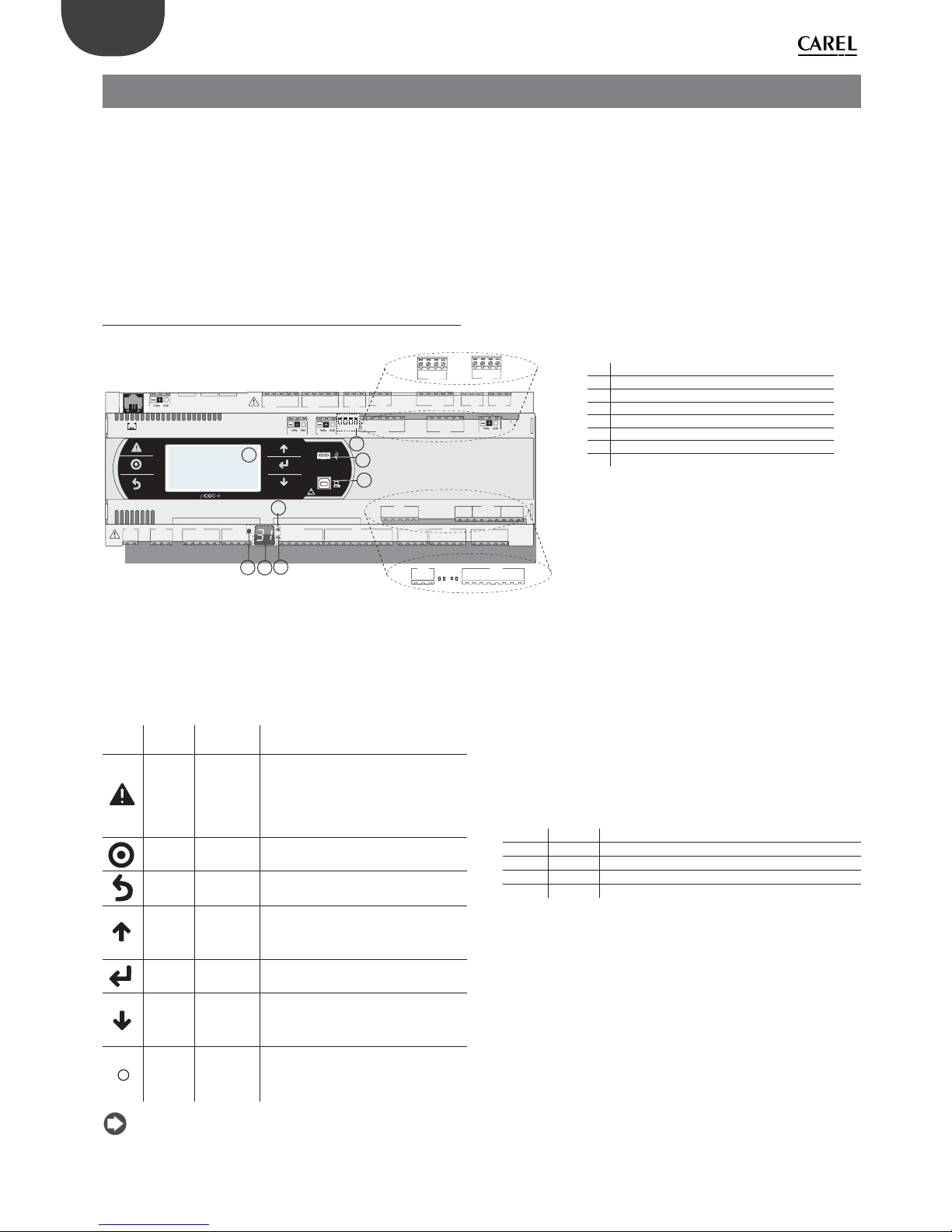
Each controller is provided with connectors for the inputs/outputs (see
chap. 5) and the secondary display, which has a button and a LED for
setting the pLAN address. Depending on the model, it can be supplied
with a built-in terminal and USB ports.
Keypad
Button Descr. Backlighting Functions
Alarm White/Red
• press together with UP while providing
power to change the controller’s address
(see par. 6.3).
• press together with Enter to access the
screens managed by the BIOS (see par.
6.6).
Prg White/Yellow -
Esc White go up one level
UP White
• press together with DOWN and ENTER to
change the terminal’s address (only for
PGDE terminal - see par. 6.4).
• press to increase value.
Enter White press to confi rm value.
DOWN White
• press together with UP and ENTER to
change the terminal’s address (only for
PGDE terminal - see par. 6.4).
• press to reduce value.
pLAN
address
selection
-
• pressed briefl y: displays the pLAN
address.
• long press (>5 s): procedure for changing
pLAN address (see par. 6.3).
Note: Once the application program is installed, all button
functions depend on the program and do not necessarily correspond to
the descriptions above.
Display
The controller is provided with two displays:
• the main display on the built-in terminal (if included);
• the secondary display showing the controller’s pLAN address.
LED
The more complete models are provided with 6 LEDs:
• 1 yellow LED indicating that the device is powered;
• 1 red LED indicating an overload on the +VDC (J2-5) terminal;
• 4 LEDs indicating valve status (only on pCO5+ built-in driver models).
Flashing LEDs mean the valve is moving; steadily-on LEDs mean the
valve is completely open or closed.
LED Colour Description
A Yellow close valve A (connector J27)
B Green open valve A (connector J27)
C Yellow close valve B (connector J28)
D Green open valve B (connector J28)
Microswitches
Four microswitches are provided to confi gure port J26 as a Fieldbus or
BMS port (see “Port J26 confi guration”).
USB ports
On the models where they are included, there are 2 USB ports which can
be accessed after removing the cover:
• a “host” USB port for connecting pendrives;
• a “slave” USB port for direct connection to the USB port of a computer
on which pCO Manager is installed, which can be used to upload the
application program, commissioning the system, etc.
Key:
A pLAN address selection button
B pLAN address display(*)
C Power LED
D Overload LED
E J26 port Fieldbus/BMS microswitches(*)
F Host USB port (master)(*)
G Slave USB port (device)(*)
H Main display
(*) available on P+5... models; not available on P+3...
models; see par. 8.3.
13
ENG
pCO5plus +0300020EN rel. 1.2 - 07.11.2013
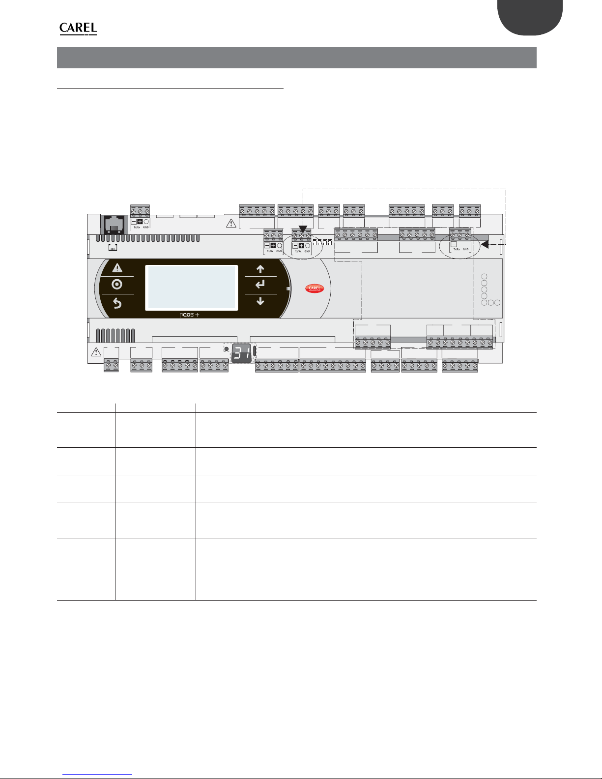
3. COMMUNICATION PORTS
3.1 Serial ports
Compared to the pCO3, pCO5+ (and pCO5) controllers have a second
BMS serial port on connector J25 (BMS2) and a second Fieldbus port
on connector J26 (FBus2). pCO5+ Large and Extralarge boards still have
connector J23, which is marked FBus2 like connector J26. With reference
to management under 1Tool, this is the same serial line, so diff erent
addresses must be used for devices connected to both connectors,
while from the electrical point of view the ports are independent (an
electrical fault on port J26 does not aff ect port J23). See the “Technical
Specifi cations” table.
C1
NO1
NO2
NO3
C1
C4
NO4
NO5
NO6
C4
C7
NO7C7NO8
C8
NC8
NO12
C12
NC12
NO13
C13
NC13
C9
NO9
NO10
NO11
C9
G
G0
U1U2U3
GND
+VDC
+Vterm
GND
+5 VREF
U4
GNDU5GND
VG
VG0Y1Y2Y3Y4
ID1
ID2
ID3
ID4
ID5
ID6
ID7
ID8
IDC1
U6U7U8
GND
ID9
ID10
ID11
ID12
IDC9
ID13H
ID13
IDC13
ID14
ID14H
J1
J24 J2 J3
J4
J5 J7
J8
J20
J21
J14
J10
J13
J12
J22
J16
J17
J18
J15
J6
J19
NO14
C14
NC14
NO15
C15
NC15
C16
NO16
NO17
NO18
C16
ID15H
ID15
IDC15
ID16
ID16H
Y5
Y6
ID17
ID18
IDC17
U9
GND
U10
GND
FieldBus card BMS card
J23 FBus2
J11 pLAN
J25 BMS2
J26 FBus2
43 2 1
ONLY F OR
LARGE AND EXTRALARGE
MODELS
Fig. 3.a
Serial Type/Connector Features
Serial ZERO pLAN/J10, J11
• Built into main board
• HW driver: asynchronous half duplex RS485 pLAN
• Not optically isolated
• Connectors: telephone jack + 3-pin plug-in connector
Serial ONE BMS 1 Serial Card
• Not built into main board
• HW driver: not present
• Can be used with all the BMS expansion cards of the pCO family
Serial TWO FieldBus 1 Serial Card
• Not built into main board
• HW driver: not present
• Can be used with all Fieldbus expansion cards of the pCO family
Serial THREE BMS 2 / J25
• Built into main board
• HW driver: asynchronous half duplex RS485 slave
• Optically-isolated/non-optically-isolated serial
• 3-pin plug-in connector
Serial FOUR FieldBus 2 / J26
(and J23 on Large and
Extralarge versions)
• Built into main board
• HW driver: asynchronous half duplex RS485 Master or Slave (see par. 3.2)
• J23: not optically isolated
• J26: optically isolated/not optically isolated
• 3-pin plug-in connector
• J23 and J26 are both managed by the same protocol as serial 4, with the advantage of being electrically
independent.
Tab. 3.a

14
ENG
pCO5plus +0300020EN rel. 1.2 - 07.11.2013
3.2 Port J26 confi guration
Compared to the pCO5, pCO5+ controllers are provided with 4
microswitches for confi guring serial port J26 (fi gure):
• microswitches all down: port J26 set with Fieldbus hardware;
• microswitches all up: port J26 set with BMS hardware*.
Factory confi guration: Fieldbus port.
(*) At the software level, in the 1Tool programming environment the serial
port is still the Fieldbus2.
C1
NO1
NO2
NO3
C1
C4
NO4
NO5
NO6
C4
C7
NO7C7NO8
C8
NC8
FieldBus
43 2 1
BMS
1234
BMS
FieldBus
J26
J26
Fig. 3.b
3.3 Controller network connections
The pCO5+ comes with three kinds of serial ports: pLAN, Fieldbus, BMS.
The RS485 Fieldbus serial port is designed with Master-type hardware,
while the RS485 BMS serial port has Slave-type hardware. The protocols
used on the RS485 Fieldbus port are, due to the nature of the port, Master
protocols (CAREL Master or Modbus RTU Master), although in special
cases Slave protocols can be used (CAREL Slave or Modbus RTU Slave),
adopting the necessary measures. Likewise, Slave protocols are applied
on the RS485 BMS port, although under certain conditions Master
protocols can also be used.
Note: The pLAN network is multi-master, meaning that each
controller can work as Master or Slave at the same time.
J25 BMS2 J26 FBus2
J11 pLAN
pCO5+
MASTER
J25 BMS2
J26 FBus2
J11 pLAN
pCO5+
J25 BMS2 J26 FBus2
J11 pLAN
pCO5+
MASTER - SLAVE network
SLAVE SLAVE
Fig. 3.c
PC
MASTER
J25 BMS2
J26 FBus2
J11 pLAN
pCO5+
J25 BMS2 J26 FBus2
J11 pLAN
pCO5+
SLAVE
SLAVE
Fig. 3.d
pLAN network
J25 BMS2 J26 FBus2
J11 pLAN
pCO5+
J25 BMS2 J26 FBus2
J11 pLAN
pCO5+
J25 BMS2 J26 FBus2
J11 pLAN
pCO5+
MASTER/SLAVE
MASTER/SLAVEMASTER/SLAVE
Fig. 3.e
Important warnings:
• By applying the appropriate impedance, a serial port with Master
(FBus) hardware supplies the network with the bias voltage required to
run all the connected devices, i.e. the master itself and its slaves.
• Conversely, serial ports with slave hardware (BMS) do not provide bias
voltage, so it is always advisable to connect at least one device with
master hardware (FBus) to the network so that it is correctly biased.
• However, no more than two devices with master hardware (FBus) can
be connected to the same network, otherwise the network’s total
bias impedance becomes too small and incapable of supplying the
required voltage to the RS485 network.
• We recommend connecting the serial probes or other fi eld devices to
an optically-isolated version of the Fieldbus serial port or to serial port
TWO – Fieldbus 1 to exploit the fi ltering properties of optical isolation.
Special cases
• In networks consisting only of slave HW devices, no more than 207
devices can be connected. The max. length allowed for the network
is 100 m.
DO NOT connect the 120, 1/4W terminating resistors to the rst
and last devices;
• In networks consisting only of Master HW devices, no more than 2
devices can be connected. The max. length allowed for the network
is 1000 m. If the network is longer than 100 m, apply the 120Ω, 1/4W
terminating resistors to the fi rst and last devices in the network;
• connect the computer to a network with no more than 1 master HW
device or no more than 207 slave HW devices.

15
ENG
pCO5plus +0300020EN rel. 1.2 - 07.11.2013
4. INSTALLATION
4.1 Mounting on DIN rail and dimensions
The controller is designed to be mounted on a DIN rail. The fi gure below
shows the dimensions for each size.
Mounting:
• place the controller on the DIN rail and press it down gently. The tabs
at the back will snap into place and lock the controller.
Removing:
• lift the tabs using a screwdriver applied to their release slots. The tabs
are kept in place by springs.
pCO5+
pGDE
pGD1*
A
110
45
B
44
156
125
67
18
30
82
202
53
43
177
Fig. 4.a
DIMENSIONS (mm)
Small Medium Buit-in driver Large Extralarge
A 227,5 315 315 315 315
B 60 60 60 60 60
B - with USB port/built-in terminal
70 70 70 70 70
B - with ULTRACAP module
-- 75 --
Tab. 4.a
4.2 Installation
Environmental conditions
Avoid installing the controller and the terminal in places with:
• exposure to direct sunlight and to the elements in general;
• temperature and humidity outside the product’s range of operation
(see “Technical Specifi cations”);
• large, rapid fl uctuations in room temperature;
• strong magnetic and/or radio frequency interference (avoid installing
near transmitting antennas);
• strong vibrations or knocks;
• presence of explosives or fl ammable gas mixtures;
• exposure to aggressive and polluting atmospheres (e.g. sulphur and
ammonia vapours, salt mist, fumes) that can cause corrosion and/or
oxidation;
• exposure to dust (formation of a corrosive patina with possible
oxidation and reduced insulation);
• exposure to water.
Positioning the controller inside the electrical panel
Install the controller inside an electrical panel in a position where it cannot
be reached and is protected from knocks or impacts. The controller should
be placed inside the panel in a position where it is physically separated
from power components (solenoids, contactors, actuators, inverters,
etc.) and their respective cables. The ideal solution is to house these two
circuits in two separate cabinets. Proximity to such devices/cables may
cause random malfunctions that are not immediately evident. The panel’s
casing must allow an adequate fl ow of cooling air.

16
ENG
pCO5plus +0300020EN rel. 1.2 - 07.11.2013
Important:
• For safety reasons the controller should be installed inside an electrical
panel so that the only accessible parts are the display and the built-in
terminal’s keypad.
• Install the controller so that the disconnection devices can be used
safely and without hindrance.
• When laying out the wiring, separate as much as possible the probe
cables, digital input cables and serial line cables from the power
cables (connected to contactors, thermomagnetic devices, etc.) avoid
electromagnetic interference.
• Never run power cables and probe signal cables in the same conduits
(including the ones in the electrical panels).
• For control signals, use shielded cables with twisted wires. If the control
cables have to cross over power cables, the intersections should be as
close as possible to 90 degrees; under no circumstances should the
control cables be laid parallel to the power cables.
• Keep the paths of the probe cables as short as possible and avoid
making spiral paths that enclose power devices.
• In case of malfunctions do not attempt to repair the device, but
contact a CAREL service centre.
Electrical installation
Important: Before servicing the equipment in any way disconnect
the controller from the power mains by putting the system’s main switch
on OFF.
Make sure the system is provided with a power disconnector conforming
to regulations. Use cable lugs that are suitable for the terminals used.
Loosen each screw and insert the cable lugs, then tighten the screws.
There is no limit to the number of wires that can be connected to
each individual terminal. When tightening the terminal screws apply
a tightening torque no greater than 0.6 Nm. For information on the
maximum allowable length of the connections to the analogue/digital
inputs and to the analogue outputs please refer to the “Technical
Specifi cations” table. In environments subject to strong disturbance use
shielded cables with the braiding bonded to the earthing conductor
in the electrical panel. The terminals can accept wires with a maximum
cross-section of 2.5 mm2 (12 AWG). After making the connection, gently
tug on the cables to make sure they are suffi ciently tight.
Note:
• secure the cables connected to the controller with clamps placed at 3
cm from the connectors;
• if the power transformer's secondary winding is earthed, make sure
the earth conductor is bonded to the conductor that goes to the
controller and is connected to terminal G0. This applies to all the
devices connected to the controller through a serial network.
Important:
• Using a supply voltage other than specifi ed can seriously damage the
system.
• Connect the fuse close to the controller.
• Installing, servicing and inspecting the controller should be done
only be qualifi ed personnel and in compliance with national and local
regulations.
• All the very low voltage connections (24 Vac/Vdc or 28 to 36 Vdc
analogue and digital inputs, analogue outputs, serial bus connections,
power supplies) must have reinforced or double insulation from the
power mains.
• Avoid touching or nearly touching the electronic components
mounted on the boards to avoid electrostatic discharges from the
operator to the components, which can be very damaging.
• Do not press the screwdriver on the connectors with excessive force,
to avoid damaging the controller.
• Using the device in any way other than specifi ed by the Manufacturer
can compromise its protection system.
• Use only optional boards and connectors supplied by CAREL.
4.3 Preliminary operations
Installing the serial cards
If the Fieldbus and BMS serial cards built into the pCO5+ are insuffi cient
for the required application, you can add a Fieldbus serial port and a BMS
serial port, which are available as accessories (see chap.1).
To install them, proceed as follows:
1. Locate the Fieldbus or BMS serial port.
2. Using a screwdriver, take off the cover.
3. Using a pair of nippers, cut out the perforated plastic part to create
an opening.
4. Plug the optional card into the edge-card connector, making sure it
is fi rmly secured and makes contact.
5. Put back the cover so that the serial card’s connector is aligned with
the opening.
6. Make the electrical connections required.
FieldBus card
BMS card
Fig. 4.b
Note: For details, refer to the instructions sheets of the cards to
install.
Installing the pCOe expansion card
See instructions sheet code +050003265.
Installing the Ultracap module
See instructions sheets codes +0500042IE and +0500041IE.
4.4 Serial network electrical connections
To improve the controller’s immunity against electromagnetic
interference, the serial connection cable should be a shielded twisted
pair cable, 2-pole or 3-pole depending on the insulation of the serial
connection. The following rule applies:
• if the serial port is isolated (functionally) from the power supply, a third
wire is required in the serial cable to act as a common reference for the
controllers. If the serial port is not optically isolated and the common
reference is already present, no third wire is required.
Technical specifi cations for connections
Use a shielded, twisted pair cable (AWG 20-22) with inter-conductor
capacitance <90pF/m.
Master
device
HW Lmax(m) Wire/
wire
capaci-
tance
(pF/m)
Resistance on
fi rst and last
devices
Max. no.
of slave
devices on
bus
Data rate
(bit/s)
FBUS
RS485
1000
< 90 120 Ω 64 19200
PC 1000
< 90 120 Ω 207 38400
pLAN 500
< 90 - 32
62500/
115200
Tab. 4.b
Note: In case of a Master–Slave network the max. allowable length
is 1000 m. If the network is longer than 100 m, apply 120Ω, 1/4W
terminating resistors to the fi rst and last devices in the network.
Non-optically-isolated serial port
This is the case of the serial ZERO - pLAN (J11), Fieldbus 2 (J23 and J26)
and BMS2 if not optically isolated (on models with built-in ports that are
not optically isolated).

17
ENG
pCO5plus +0300020EN rel. 1.2 - 07.11.2013
Optically-isolated serial port
This is the case of serial ONE - BMS1, serial TWO - Fieldbus 1 and the builtin ports serials THREE and FOUR on optically-isolated models. Regardless
of the type of power supply or earthing, use a 3-pole shielded cable
connected as shown in the fi gure. If the network is more than 100 m
long, the terminating resistor is required.
J25 BMS2 J26 FBus2
J11 pLAN
pCO5+
G
G0
J25 BMS2
J26 FBus2
J11 pLAN
pCO5+
G
G0
J25 BMS2 J26 FBus2
J11 pLAN
pCO5+
G
G0
R = 120 Ω
R = 120 Ω
Power
supply
Fig. 4.f
The procedure for earthing the shield is described in the following
paragraph.
Procedure for earthing the shield
The shield of the serial cable is earthed diff erently according to the
length, as shown in the fi gure (where A=FBus terminal, B=BMS terminal,
or A=B in pLAN).
Case 1: Distance between controllers less than 0.3 m: earth only one end
of the cable.
L < 300 mm
L < 300 mm
AB B
Fig. 4.g
Case 2: Distance between controllers greater than 0.3 m: two possibilities.
a): Earth one end with a bridge between the shields.
L >300 mm
L > 300 mm
AB B
Fig. 4.h
b): Earth both ends of the cable.
L >300 mm
L > 300 mm
AB B
Fig. 4.i
Case 1: Multiple boards connected to a Master/Slave network powered
by the same transformer. This is a typical application of multiple boards
connected inside the same electrical panel. Terminating resistors are not
required (L<100m).
230 Vac
24 Vac
L
N
J25 BMS2 J26 FBus2
J11 pLAN
pCO5+
G
G0
J25 BMS2
J26 FBus2
J11 pLAN
pCO5+
G
G0
J25 BMS2 J26 FBus2
J11 pLAN
pCO5+
G
G0
Fig. 4.c
The procedure for earthing the shield is described in the following
paragraph.
Case 2: Multiple boards connected to a Master/Slave network powered
diff erent transformers (with G0 not earthed); this is a typical application
of multiple boards inside diff erent electrical panels. If the network is more
than 100 m long, the 120 Ω, ¼ W terminating resistor is required.
J25 BMS2 J26 FBus2
J11 pLAN
pCO5+
G
G0
J25 BMS2
J26 FBus2
J11 pLAN
pCO5+
G
G0
J25 BMS2 J26 FBus2
J11 pLAN
pCO5+
G
G0
230 Vac
24 Vac
L
N
230 Vac
24 Vac
L
N
230 Vac
24 Vac
L
N
R = 120 Ω
R = 120 Ω
Fig. 4.d
The procedure for earthing the shield is described in the following
paragraph.
Note: The diagrams for cases 1 and 2 also apply to pLAN networks
with the connection cable connected to terminals J11.
Case 3: Multiple boards connected to the pLAN network powered by
diff erent transformers with only one earth reference. This is a typical
application of multiple boards inside diff erent electrical panels.
J25 BMS2 J26 FBus2
J11 pLAN
pCO5+
G
G0
J25 BMS2
J26 FBus2
J11 pLAN
pCO5+
G
G0
J25 BMS2 J26 FBus2
J11 pLAN
pCO5+
G
G0
230 Vac
24 Vac
L
N
230 Vac
24 Vac
L
N
230 Vac
24 Vac
L
N
Fig. 4.e
The procedure for earthing the shield is described in the following
paragraph.
Important: The earth connection (if any) should be made only on
one point of the earth line (same earthing terminal for all controllers).

18
ENG
pCO5plus +0300020EN rel. 1.2 - 07.11.2013
4.5 Connecting the terminal
The controller and the terminal are connected to a pLAN network.
1: One pCO controller
When connecting the controller to the terminal, the following restrictions
should be kept in mind:
1. the overall length of the pLAN network should not exceed 500 m.
Consequently, if the terminal is installed remotely the length of the
terminal cable must be included in the total length;
2. the unshielded telephone cable can be used for a max. length of 50
m. Beyond this length use a 3-pole shielded cable (see table below);
3. in case of lengths greater than 200 m, the power supply for the
terminal must be provided separately;
4. no more than 3 terminals can be connected to the same pCO
controller. The terminals must be of the same type (e.g. all PGD1).
One terminal is powered by the controller, and the other two by an
external power supply;
5. except for PGD0/PGD1/PGDE, the other terminals should be powered
by separate power supplies.
Important:
• In domestic installations, standard EN55014 requires the connection
cable between the controller and the terminal to be shielded, with the
shield earthed at both ends;
• In industrial installations with length >10 m, the connection cable
between the controller and the terminal must be shielded and the
shield must be earthed.
Case A: 1 terminal
A.1: Distance L < 50 m.
The typical connection for one terminal (e.g. PGD1) is made using a
6-pin telephone cable available from CAREL as an accessory (code
S90CONN00*). The telephone connector provides both data transmission
and the power supply for the terminal.
To make the connection:
• slip the connector into terminal J10 until it clicks.
To remove the connector:
• press lightly on the plastic catch on the connector and slip it out.
Graphic
L < 50 m
cavo telefonico
telephone cable
J10
J11 pLAN
Fig. 4.j
A.2: Distance 50< L< 200 m.
Lengths greater than 50 m require using two TCONN6J000 boards
connected with a 4-pin shielded cable, as shown in the fi gure. The
terminal is powered by the controller.
J10
J11 pLAN
L < 200 m
0,8 m MAX
0,8 m MAX
cavo telefonico
telephone cable
Cavo schermato
AWG20/22
2 twisted pair
6
++TXRXTX
RX
-
+-
-
543210
TCONN6J000
6543210
6543210
cavo telefonico
telephone cable
Fig. 4.k
Note: For information on the position of the jumpers on board
TCONN6J000, see instructions sheet code +050002895.
A.3: Distance 200< L< 500 m.
The terminal must be powered by an external power supply. Connect a
3-pole shielded cable to connector pLAN J11. Provide a separate power
supply for board TCONN6J000, as shown in the fi gure.
on/off alarm enter
menu I/O set prog.
?
info
Graphic
G
G0
U1u2U3
GND
+Vterm
GND
+5 VREF
J1
J24 J2
J10
J11 pLAN
L < 500 m
J14 and J15 on 2-3
on TCONN6J000
AWG20/22
2 twisted pair
6543210
+
-
alimentatore
power supply
20...30 Vdc -150 mA
Fig. 4.l
Note: To reach the maximum length of the network use a bus
layout with branches not exceeding 5 m.
Case B: 2 terminals
Two terminals can be directly connected only on a Small model. Models
of other sizes require the second terminal to be powered separately. On
Medium/Large/Extralarge controllers apply the known confi guration A.1
or A.2 + A.3.
B.1: Distance L <50 m
Use 1 TCONN6J000 board connected as shown in the fi gure.
cavo telefonico
telephone cable
J10
J11 pLAN
TCONN6J000
6543210
on/off alarm enter
menu I/O set prog.
?
info
Graphic
on/off alarm enter
menu I/O set prog.
?
info
Graphic
0,8 m MAX
L < 50 m
L < 50 m
Fig. 4.m

19
ENG
pCO5plus +0300020EN rel. 1.2 - 07.11.2013
B.2 Distance 50< L< 200 m.
Use 3 TCONN6J000 boards connected as shown in the fi gure.
J10
J11 pLAN
L < 200 m
L < 200 m
6543210
cavo telefonico
telephone cable
6543210
6543210
on/off alarm enter
menu I/O set prog.
?
info
Graphic
on/off alarm enter
menu I/O set prog.
?
info
Graphic
0,8 m MAX
Fig. 4.n
B.3 Distance 200< L< 500 m.
If one of the terminals is connected at a distance >200 m, connect it
according to the layout described in A.3. Connect the other terminal as
described in A.1 or A.2. If both terminals are close to a distance >200 m,
connect them as shown in the layout below.
on/off alarm enter
menu I/O set prog.
?
info
Graphic
on/off alarm enter
menu I/O set prog.
?
info
Graphic
G
G0
U1u2U3
GND
+Vterm
GND
+5 VREF
J1
J24 J2
J10
J11 pLAN
J31
CANL
CANH
GND
L < 500 m
J14 and J15 on 2-3
on TCONN6J000
AWG20/22
1 twisted pair
6543210
+
-
alimentatore
power supply
20...30 Vdc -150 mA
Fig. 4.o
Case C: 3 terminals
For the fi rst 2 terminals refer to Case B. For the third terminal use one of
connections A.1, A.2 or A.3.
Important:
• except for pGD1, the other terminals should be always powered by
separate power supplies;
• the 24 Vdc on the +Vterm (J24) terminal can be used only in alternative
to connector J10 to power an external terminal, with maximum current
1.5 W;
• in networks with star layout, if the cable is longer than 5 m connect
the terminal only to the fi rst or last pCO5+ in the network (to avoid
branches).
The following table applies.
Type of
cable
MAX distance
controller-terminal (m)
Power supply
Board TCONN6J000 used
1 Telephone 50
Provided by con-
troller (150 mA)
NO
2
AWG24
shielded
200
Provided by con-
troller (150 mA)
YES
3
AWG20/22
shielded
500 Separate YES
Tab. 4.c
2: pCO controller in pLAN network
If a terminal is connected to a pCO controller which is itself connected
to other controllers in a pLAN network, the terminal is directly powered
by the controller. Be sure to avoid the terminal being powered by two
power supplies. For that purpose, set jumpers J14 and J15 on board
TCONN6J000 to interrupt the supply current.
T
T
T
C
B
AA
A
B
B
C
C
Term 1
Term 2
Term n
sc
sc
sc
J14/J15 ON 2-3
Term n+ 1
no 30V=
AWG24
(2 twisted pair)
AWG24
(2 twisted pair)
AWG24
(3 twisted pair)
J14/J15 ON 2-3
J14/J15 ON 1-2
G
G0
U1u2U3
GND
+Vterm
GND
+5 VREF
J1
J24 J2
J10
J11 pLAN
G
G0
U1u2U3
GND
+Vterm
GND
+5 VREF
J1
J24 J2
J10
J11 pLAN
G
G0
U1u2U3
GND
+Vterm
GND
+5 VREF
J1 J24 J2
J10
J11 pLAN
no 30V=
30V=
Fig. 4.p
When setting up a pLAN network with pCO controllers and terminals,
each pCO5+ controller can power only 1 PGD1/E terminal (except for the
Small model, which can power 2 terminals). When you need to connect
more than one terminal, you will have to provide an independent power
supply. See instructions sheet code +050002895.
4.6 Input/output labels
pCO5+ controllers are distinguished by size and provided with inputs
and outputs and power supplies for the active probes most suitable for
various applications.
The features that depend on the model are:
• maximum number and type of inputs/outputs;
• availability of built-in driver for expansion valves.
Label Type of signal
U... Universal inputs/outputs, confi gurable via software as:
Analogue inputs:
- NTC, PTC, PT500, PT1000 sensors
- PT100 sensors
- 0 to1 Vdc or 0 to 10 Vdc signals
- 0/4 to 20 mA signals
- 0 to 5 V signals for ratiometric probes
Digital inputs (not optically isolated):
- potential-free contacts (not optically isolated)
- fast digital inputs
Analogue outputs (not optically isolated):
- 0 to 10 Vdc signals
- PWM signals
Y... 0 to 10 Vdc analogue outputs, PWM outputs
ID... 24 Vac/24 Vdc digital input
ID...H 230 Vac digital input
NO... Relay output, normally open contact
NC... Relay output, normally closed contact
C... Relay output, common
Tx/Rx, GND Serial port
Tab. 4.d

20
ENG
pCO5plus +0300020EN rel. 1.2 - 07.11.2013
4.7 I/O table
pCO5+ Controllers pCOE I/O expansion card
Small
Medium
Large
Extra
Large
Built-in
driver
Label
In/Out
Tipo
PCOE*
Label
In/Out
Type
Universal inputs/
outputs
NTC input 5 8 10 8 8 U I n Universal I/O 4 B I n Analogue input(*)
PTC input 5 8 10 8 8 U In Universal I/O - - - PT500 input 5 8 10 8 8 U I n Universal I/O - - - PT1000 input 5 8 10 8 8 U In Universal I/O - - - PT100 input max 2 max 3 max 4 max 3 max 3 U In Universal I/O - - - 0 to 1 Vdc/0 to 10 Vdc input (**)
(powered by controller)
Tot. max 55Tot. max 8
max 6
Tot. max 10
max 6
Tot. max
8
max 6
Tot. max
8
max 6 U In Universal I/O 4 B In Analogue input(*)
0 to 1 Vdc/0 to 10 Vdc input (**)
(external power supply)
5 8 10 8 8 U In Universal I/O 4 B In Analogue input(*)
0 to 5 Vdc input - - - - - - - - 4 B In Analogue input(*)
0 to 20 mA/4 to 20 mA input
(powered by controller)
Tot. max
4
max 4
Tot. max
7
max 6
Tot. max
9
max 6
Tot. max
7
max 6
Tot. max
7
max 6 U In Universal I/O 4 B In Analogue input(*)
0 to 20 mA/4 to 20 mA input
(external power supply)
max 4 max 7 max 9 max 7 max 7 U In Universal I/O - - - -
0 to 5 V input for ratiometric probe
(+5Vref)
max 5 max 6 max 6 max 6 max 6 U In Universal I/O 4 B In Analogue input(*)
Voltage-free contact digital input 5 8 10 8 8 U In Universal I/O -- -Digital input
Fast digital inputs max 2 max 4 max 6 max 4 max 4 U In Universal I/O -- -Digital input
Non-optically-isolated 0 to 10 Vdc
output
5 8 10 8 8 U Out Universal I/O -- -Analogue output
Non-optically-isolated PWM output 5 8 10 8 8 U Out Universal I/O -- -Analogue output
max tot 5 max tot 8 max tot 10 max tot 8 max tot 8
Digital inputs
Optically-isolated 24 Vac/Vdc input 8 12 14 12 12 ID In Digital input 4 ID I n Digital input
24 Vac/Vdc or 230 Vac (50/60 Hz) input - 2 4 2 2 ID In Digital input - - -
max tot 8 max tot 14 max tot 18 max tot 14 max tot 14
Analogue outputs
Optically-isolated 0 to 10 Vdc output 4 4 6 4 4 Y Out
Analogue output
1 Y Out
Optically-isolated PWM output 2 2 2 2 2 Y3, Y4 Out
Analogue output
-- -
Output for two-pole stepper motor - - - - 1/2 1-3-2-4 Out
Analogue output
-- -
max tot 4 max tot 4 max tot 6 max tot 4 max tot 6
Digital outputs
NO/NC relay output 1 3 5 3 3
NO/NC Out Digital output 4 NO/NC Out Digital output
NO relay output 7 10 13 26 10
NO Out Digital output -- -
24 V SSR output
1 2 3/4 2 2 NO/NC Out Digital output -- -
230 V SSR output 1 13 3/4 2 2 NO/NC Out Digital output -- -
max tot 8 max tot 13 max tot 18 max tot 29 max tot 13
25 39 52 55 41
Total I/O
Power to terminal
1 1 1 1 1 J10
Telephone conn.
(pLAN) J10
1 1 1 1 1 +Vterm
Add’l power to
terminal
Power to probes
1 1 1 1 1 +VDC
Power to active
probes
1 1 1 1 1 +5 VREF
Power to
ratiometric probes
Power to analogue
outputs
1 1 1 1 1 VG, VG0 1 VG,VG0
pLAN ports
1 1 1 1 1 J10 Signal and power
1 1 1 1 1 J11 Signal only
Built-in Fieldbus ports 1 1 2 2 1 J23/ J26
Accessory Fieldbus
ports
1 1 1 1 1 Fbus card
Built-in BMS ports 1 1 1 1 1 J25
Accessory BMS ports 1 1 1 1 1 BMS card
Host USB port (if
included)
1111 1
Slave USB port (if
included)
1111 1
(*) On the pCOE expansion board the inputs can be selected two by two (B1, B2 and B3, B4) via software
(**) pCOE board: only 0...1V inputs
Tab. 4.e

21
ENG
pCO5plus +0300020EN rel. 1.2 - 07.11.2013
4.8 Small and Medium pCO5+: connecting terminals
C1
NO1
NO2
NO3
C1
C4
NO4
NO5
NO6
C4
C7
NO7C7NO8
C8
NC8
G
G0
U1U2U3
GND
+VDC
+Vterm
GND
+5 VREF
U4
GNDU5GND
VG
VG0Y1Y2Y3Y4
ID1
ID2
ID3
ID4
ID5
ID6
ID7
ID8
IDC1
J1
J24 J2 J3
J4
J5
J14
J10
J13
J12
J15
FieldBus card BMS card
J11 pLAN
J25
BMS2
J26
FBus2
43 2 1
4
5
10
18
1
6
2
16 17
11 12
3
3
7
8
15
13 14
Fig. 4.q
C1
NO1
NO2
NO3
C1
C4
NO4
NO5
NO6
C4
C7
NO7C7NO8
C8
NC8
NO12
C12
NC12
NO13
C13
NC13
C9
NO9
NO10
NO11
C9
G
G0
U1U2U3
GND
+VDC
+Vterm
GND
+5 VREF
U4
GNDU5GND
VG
VG0Y1Y2Y3Y4
ID1
ID2
ID3
ID4
ID5
ID6
ID7
ID8
IDC1
U6U7U8
GND
ID9
ID10
ID11
ID12
IDC9
ID13H
ID13
IDC13
ID14
ID14H
J1
J24 J2 J3
J4 J5 J7
J8
J14
J10
J13
J12
J16
J17
J18
J15
J6
FieldBus card B MS card
J11 pLAN
J25
BMS2
J26
FBus2
43 2 1
4
5
1
6
2
3
3
3 8
9
7 8
10 13 14
11
12
15
18
16
17
Fig. 4.r
Ref. Description Ref. Description
1 POWER CONNECTOR G+, G0 11 pLAN plug-in connector
2
+Vterm: power to additional terminal
+5 VREF power to ratiometric probes
12 Reserved
3 Universal inputs/outputs 13 Reserved
4 +VDC: power to active probes 14 Reserved
5 Button for setting pLAN address, secondary display, LEDs 15 Relay digital outputs
6
VG: voltage A(*) to optically-isolated analogue output
VG0: power to optically-isolated analogue output, 0 Vac/Vdc
16 BMS2 connector
7 Analogue outputs 17 Fieldbus2 connector
8 ID: digital inputs at voltage A(*) 18 Fieldbus/BMS selector microswitch
9
ID..: digital inputs at voltage A(*)
IDH..: digital inputs at voltage B(**)
10 pLAN telephone connector for terminal/downloading application program
(*) Voltage A: 24 Vac or 28 to 36 Vdc; (**) Voltage B: 230 Vac - 50/60 Hz.

22
ENG
pCO5plus +0300020EN rel. 1.2 - 07.11.2013
4.9 Large and Extralarge pCO5+: connecting terminals
C1
NO1
NO2
NO3
C1
C4
NO4
NO5
NO6
C4
C7
NO7C7NO8
C8
NC8
NO12
C12
NC12
NO13
C13
NC13
C9
NO9
NO10
NO11
C9
G
G0
U1U2U3
GND
+VDC
+Vterm
GND
+5 VREF
U4
GNDU5GND
VG
VG0Y1Y2Y3Y4
ID1
ID2
ID3
ID4
ID5
ID6
ID7
ID8
IDC1
U6U7U8
GND
ID9
ID10
ID11
ID12
IDC9
ID13H
ID13
IDC13
ID14
ID14H
J1
J24 J2 J3
J4 J5 J7
J8
J20
J21
J14
J10
J13
J12
J22
J16
J17
J18
J15
J6
J19
NO14
C14
NC14
NO15
C15
NC15
C16
NO16
NO17
NO18
C16
ID15H
ID15
IDC15
ID16
ID16H
Y5
Y6
ID17
ID18
IDC17
U9
GND
U10
GND
FieldBus card BMS card
J23 FBus2
J11 pLAN
J25
BMS2
J26
FBus2
43 21
4
5
1
6
2 3 3 3 8
9
7 8
10
11 12
15
18
16 17 1915 15
9 7 3 8
13 14
N.O. Model
N.C. Model
J22
C16
NC16
NC17
NC18
C16
Fig. 4.s
C1
NO1
NO2
NO3
C1
C4
NO4
NO5
NO6
C4
C7
NO7C7NO8
C8
NC8
NO12
C12
NC12
NO13
C13
NC13
C9
NO9
NO10
NO11
C9
G
G0
U1U2U3
GND
+VDC
+Vterm
GND
+5 VREF
U4
GNDU5GND
VG
VG0Y1Y2Y3Y4
ID1
ID2
ID3
ID4
ID5
ID6
ID7
ID8
IDC1
U6U7U8
GND
ID9
ID10
ID11
ID12
IDC9
ID13H
ID13
IDC13
ID14
ID14H
J1
J24 J2 J3
J4 J5 J7
J8
J14
J10
J13
J12
J16
J17
J18
J15
J6
FieldBus card BMS card
J23 FBus2
J11 pLAN
J25
BMS2
J26
FBus2
43 2 1
4
5
1
6
2 3 3 3 8
9
7 8
10
11 12
15
18
16 17 1915 15
C25
NO25
NO26
NO27
NO28
NO29
C25
J20
C21
NO21
NO22
NO23
NO24
C21
J19
15
13 14
C14
NO14
NO15
NO16
C14
J21
J22
C17
NO17
NO18
NO19
NO20
C17
Fig. 4.t
Ref.
Description
Ref.
Description
1 POWER CONNECTOR G+, G0 11 pLAN plug-in connector
2
+Vterm: power to additional terminal
+5 VREF power to ratiometric probes
12 Reserved
3 Universal inputs/outputs 13 Reserved
4 +VDC: power to active probes 14 Reserved
5 Button for setting pLAN address, secondary display, LEDs 15 Relay digital outputs
6
VG: voltage A(*) to optically-isolated analogue output
VG0: power to optically-isolated analogue output, 0 Vac/Vdc
16 BMS2 connector
7 Analogue outputs 17 Fieldbus2 connector
8 ID: digital inputs at voltage A(*) 18 Fieldbus/BMS selector microswitch
9
ID..: digital inputs at voltage A(*)
IDH..: digital inputs at voltage B(**)
19 Fieldbus2 connector
10 pLAN telephone connector for terminal/downloading application program
(*) Voltage A: 24 Vac or 28 to 36 Vdc; (**) Voltage B: 230 Vac - 50/60 Hz.

23
ENG
pCO5plus +0300020EN rel. 1.2 - 07.11.2013
4.10 pCO5+ with built-in driver: connecting terminals
pCO5+ controllers come in two models, with one or two built-in drivers for electronic expansion valves.
C1
NO1
NO2
NO3
A
B
CD
C1
C4
NO4
NO5
NO6
C4
C7
NO7C7NO8
C8
NC8
NO12
C12
NC12
NO13
C13
NC13
C9
NO9
NO10
NO11
C9
G
G0
U1U2U3
GND
+VDC
+Vterm
GND
+5 VREF
U4
GNDU5GND
VG
VG0Y1Y2Y3Y4
ID1
ID2
ID3
ID4
ID5
ID6
ID7
ID8
IDC1
U6U7U8
GND
ID9
ID10
ID11
ID12
IDC9
ID13H
ID13
IDC13
ID14
ID14H
J1
J24 J2 J3
J4
J5
J7
J8
J14
J10
J13
J12
J16
J17
J18
J15
J6
FieldBus card BMS card
J11 pLAN
J25
BMS2
J26
FBus2
43 21
4
5
1
6
2 3 3 3 8
9
7 8
10
11
22 24
12
15
18
16 17
20
21
13 14
J27
132
4
J28
132
4
driver
VBAT
G0
G
J30
23
GND
VREF
S1S2S3S4DI1
DI2
J29
Fig. 4.u
Ref. Description Ref. Description
1 POWER CONNECTOR G+, G0 13 Reserved
2
+Vterm: power to additional terminal
+5 VREF power to ratiometric probes
14 Reserved
3 Universal inputs/outputs 15 Relay digital outputs
4 +VDC: power to active probes 16 BMS2 connector
5 Button for setting pLAN address, secondary display, LEDs 17 Fieldbus2 connector
6
VG: voltage A(*) to optically-isolated analogue output
VG0: power to optically-isolated analogue output, 0 Vac/Vdc
18 Fieldbus/BMS selector microswitch
7 Analogue outputs 20 Electronic valve A connector
8 ID: digital inputs at voltage A(*) 21 Electronic valve B connector
9
ID..: digital inputs at voltage A(*)
IDH..: digital inputs at voltage B(**)
22
External Ultracap module (accessory) connector
10 pLAN telephone connector for terminal/downloading application program 23 Valve driver analogue and digital inputs
11 pLAN plug-in connector 24 Valve status LEDs
12 Reserved
(*) Voltage A: 24 Vac or 28 to 36 Vdc; (**) Voltage B: 230 Vac - 50/60 Hz.
4.11 pCOE: connecting terminals
The pCOE board increases the number of inputs and outputs of a pCO5+ controller when required
by the application, without having to install a larger controller.
G
ID1
ID2
ID4
ID3
IDC1
G0
VG
GND
T+
T-
VG0
Y1
B1
B3
B4
GND
NO1
C1
NC1
NO2
C2
NC2
NO3
C3
NC3
NO4
C4
NC4
+Vdc
B2
GND
+5VRef
+5VRef
+Vdc
8
7
4
1
2
5
3
6
Fig. 4.v
Ref. Description Ref. Description
1
POWER CONNECTOR G+, G0
5 Yellow power LED and 3 indicator LEDs
2
Optically-isolated analogue output, 0 to 10 V
6 Serial address
3
RS485 network connector (GND, T+, T-) or tLAN (GND, T+)
7 Analogue inputs and power to probes
4
Optically-isolated digital inputs, at 24 Vac/Vdc
8 Relay digital outputs

24
ENG
pCO5plus +0300020EN rel. 1.2 - 07.11.2013
4.12 pCO5+ terminals description
Please refer to the fi gures in the preceding pages regarding the pCO5+.
Ref. Term. Label Description
1
J1-1 G Supply voltage A(*)
J1-2 G0 Power supply reference
2
J24-1 +Vterm Power to additional terminal
J24-2 GND Power supply common
J24-3 +5 V
REF Power to 0 to 5 V ratiometric probes
3
J2-1 U1 Universal input/output 1
J2-2 U2 Universal input/output 2
J2-3 U3 Universal input/output 3
J2-4 GND Common for universal inputs/outputs 1, 2, 3
3
J3-1 U4 Universal input/output 4
J3-2 GND Common for universal input/output 4
J3-3 U5 Universal input/output 5
J3-4 GND Common for universal input/output 5
3
J6-1 U6 Universal input/output 6
J6-2 U7 Universal input/output 7
J6-3 U8 Universal input/output 8
J6-4 GND Common for universal inputs/outputs 6, 7, 8
3
J20-3 U9 Universal input/output 9
J20-4 GND Common for universal input/output 9
J20-5 U10 Universal input/output 10
J20-6 GND Common for universal input/output 10
4 J2-5 +VDC Power to active probes
5 Button for setting pLAN address, secondary display, indicator LEDs
6
J4-1 VG Voltage A(*) to optically-isolated analogue output
J4-2 VG0
Power to optically-isolated analogue output, at 0
Vac/Vdc
7
J4-3 Y1 Analogue output 1, at 0 to 10 V
J4-4 Y2 Analogue output 2,at 0 to 10 V
J4-5 Y3 Analogue output 3, at 0 to 10 V
J4-6 Y4 Analogue output 4, at 0 to 10 V
7
J20-1 Y5 Analogue output 5, at 0 to 10 V
J20-2 Y6 Analogue output 6, at 0 to 10 V
8
J5-1 ID1 Digital input 1, at voltage A(*)
J5-2 ID2 Digital input 2, at voltage A(*)
J5-3 ID3 Digital input 3, at voltage A(*)
J5-4 ID4 Digital input 4, at voltage A(*)
J5-5 ID5 Digital input 5, at voltage A(*)
J5-6 ID6 Digital input 6, at voltage A(*)
J5-7 ID7 Digital input 7, at voltage A(*)
J5-8 ID8 Digital input 8, at voltage A(*)
J5-9 IDC1
Common for digital inputs 1 to 8 (negative pole for
DC power supply)
8
J7-1 ID9 Digital input 9, at voltage A(*)
J7-2 ID10 Digital input 10, at voltage A(*)
J7-3 ID11 Digital input 11, at voltage A(*)
J7-4 ID12 Digital input 12, at voltage A(*)
J7-5 IDC9
Common for digital inputs 9 to 12 (negative pole
for DC power supply)
8
J20-7 ID17 Digital input 17, at voltage A(*)
J20-8 ID18 Digital input 18, at voltage A(*)
J20-9 IDC17
Common for digital inputs 17 and 18 (negative
pole for DC power supply)
9
J8-1 ID13H Digital input 13, at voltage B(**)
J8-2 ID13 Digital input 13, at voltage A(*)
J8-3 IDC13
Common for digital inputs 13 and 14 (negative
pole for DC power supply)
J8-4 ID14 Digital input 14, at voltage A(*)
J8-5 ID14H Digital input 14, at voltage B(**)
9
J19-1 ID15H Digital input 15, at voltage B(**)
J19-2 ID15 Digital input 15, at voltage A(*)
J19-3 IDC15
Common for digital inputs 15 and 16 (negative
pole for DC power supply)
J19-4 ID16 Digital input 16, at voltage A(*)
J19-5 ID16H Digital input 16, at voltage B(**)
10 J10 - pLAN telephone cable connector
11
J11-1 Tx-/Rx- Tx-/Rx- pLAN RS485 port
J11-2 Tx+/Rx+ Tx+/Rx+ pLAN RS485 port
J11-3 GND GND pLAN RS485 port
12 - - Reserved
13 - - Reserved
14 - - Reserved
Ref. Term. Label Description
15
J12-1 C1 Common for relays 1, 2, 3
J12-2 NO1 Normally open contact, relay 1
J12-3 NO2 Normally open contact, relay 2
J12-4 NO3 Normally open contact, relay 3
J12-5 C1 Common for relays 1, 2, 3
15
J13-1 C4 Common for relays 4, 5, 6
J13-2 NO4 Normally open contact, relay 4
J13-3 NO5 Normally open contact, relay 5
J13-4 NO6 Normally open contact, relay 6
J13-5 C4 Common for relays 4, 5, 6
15
J14-1 C7 Common for relay 7
J14-2 NO4 Normally open contact, relay 7
J14-3 C7 Common for relay 7
15
J15-1 NO8 Normally open contact, relay 8
J15-2 C8 Common for relay 8
J15-3 CO8 Normally closed contact, relay 8
15
J16-1 C9 Common for relays 9, 10, 11
J16-2 NO9 Normally open contact, relay 9
J16-3 NO10 Normally open contact, relay 10
J16-4 NO11 Normally open contact, relay 11
J16-5 C9 Common for relays 9, 10, 11
15
J17-1 NO12 Normally open contact, relay 12
J17-2 C12 Common for relay 12
J17-3 NC12 Normally closed contact, relay 12
15
J18-1 NO13 Normally open contact, relay 13
J18-2 C13 Common for relay 13
J18-3 NC13 Normally closed contact, relay 13
15
J21-1 NO14 Normally open contact, relay 14
J21-2 C14 Common for relay 14
J21-3 NC14 Normally closed contact, relay 14
J21-4 NO15 Normally open contact, relay 15
J21-5 C15 Common for relay 15
J21-6 NC15 Normally closed contact, relay 15
J22-1 C16 Common for relays 16, 17, 18
J22-2 NO16 Normally open contact, relay 16
J22-3 NO17 Normally open contact, relay 17
J22-4 NO18 Normally closed contact, relay 18
J22-5 C16 Common for relays 16, 17, 18
15
J21-1 C14 Common for relays 14, 15, 16
J21-2 NO14 Normally open contact, relay 14
J21-3 NO15 Normally open contact, relay 15
J21-4 NO16 Normally open contact, relay 16
J21-5 C14 Common for relays 14, 15, 16
J22-1 C17 Common for relays 17, 18, 19, 20
J22-2 NO17 Normally open contact, relay 17
J22-3 NO18 Normally open contact, relay 18
J22-4 NO19 Normally open contact, relay 19
J22-5 NO20 Normally open contact, relay 20
J22-6 C17 Common for relays 17, 18, 19, 20
15
J19-1 C21 Common for relays 21, 22, 23, 24
J19-2 NO21 Normally open contact, relay 21
J19-3 NO22 Normally open contact, relay 22
J19-4 NO23 Normally open contact, relay 23
J19-5 NO24 Normally open contact, relay 24
J19-6 C21 Common for relays 21, 22, 23, 24
15
J20-1 C25 Common for relays 25, 26, 27, 28, 29
J20-2 NO25 Normally open contact, relay 25
J20-3 NO26 Normally open contact, relay 26
J20-4 NO27 Normally open contact, relay 27
J20-5 NO28 Normally open contact, relay 28
J20-6 NO29 Normally open contact, relay 29
J20-7 C25 Common for relays 25, 26, 27, 28, 29
16
J25-1 Tx-/Rx- Tx-/Rx- BMS2 RS485 port
J25-2 Tx+/Rx+ Tx+/Rx+ BMS2 RS485 port
J25-3 GND GND BMS2 RS485 port
17
J26-1 Tx-/Rx- Tx-/Rx- Fieldbus 2 RS485 port
J26-2 Tx+/Rx+ Tx+/Rx+ Fieldbus 2 RS485 port
J26-3 GND GND Fieldbus 2 RS485 port
18 Port J26 confi guration microswitches
19
J23-1 Tx-/Rx- Tx-/Rx- Fieldbus 2 RS485 port
J23-2 Tx+/Rx+ Tx+/Rx+ Fieldbus 2 RS485 port
J23-3 GND GND Fieldbus 2 network RS485 port

25
ENG
pCO5plus +0300020EN rel. 1.2 - 07.11.2013
Only for pCO5+ built-in driver:
20
J27-1 1
Electronic expansion valve 1 control (see “Electronic valve connection”).
J27-2 3
J27-3 2
J27-4 4
21
J28-1 1
Electronic expansion valve 2 control (see “Electronic valve connection”).
J28-2 3
J28-3 2
J28-4 4
22
J30-1 VBAT
Power from external Ultracap module
J30-2 G0
J30-3 G
23
J29-1 GND Common for power supply to probes
J29-2 VREF Power to driver probes
J29-3 S1 Probe 1
J29-4 S2 Probe 2
J29-5 S3 Probe 3
J29-6 S4 Probe 4
J29-7 DI1 Digital input 1
J29-8 DI2 Digital input 2
24
A, B Valve A status LED
C, D Valve B status LED
Tab. 4.f
(*): Voltage A: 24 Vac or 28 to 36 Vdc;
(**): Voltage B: 230 Vac - 50/60 Hz.
: Large model; : Extralarge model.
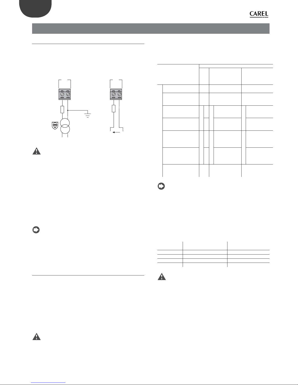
26
ENG
pCO5plus +0300020EN rel. 1.2 - 07.11.2013
5. INPUT/OUTPUT CONNECTIONS
5.1 Power supply
The fi gure below shows the power supply connection diagram. Use
a class II safety isolating transformer with short-circuit and overload
protection. See the Technical Specifi cations table for information on the
size of the transformer required by each controller model.
24 Vac
230 Vac
2.5 A T
G
G0
J1
28...36 Vdc
2.5 A T
G
G0
J1
-
+
AC
DC
Fig. 5.a
Important:
• power the pCO5+ built-in driver with AC voltage only, with the
transformer’s secondary winding earthed;
• using a supply voltage other than specifi ed can seriously damage the
controller;
• if the transformer’s secondary is earthed, make sure that the earth
conductor is connected to terminal G0. This applies to all the devices
connected to the pCO through a serial network;
• if more than one pCO board is connected to a pLAN network, make
sure that the G and G0 references are observed (G0 must be maintained
for all controllers);
• the power supply to the controller(s) and the terminal(s) should be
kept separate from the power supply to the other electrical devices
(contactors and other electromechanical components) inside the
electrical panel.
Note:
• the yellow LED on the controller lights up when the controller is
powered;
• refer to the diagrams in par. 4.4 in case of controllers connected to a
pLAN network and installed in the same electrical panel or in separate
panels.
5.2 Universal inputs/outputs
Universal inputs/outputs are distinguished by the letter U...
They can be confi gured from the application program for many diff erent
uses, such as the following:
• passive temperature probes: NTC, PTC, PT100, PT500, PT1000;
• active pressure/temperature/humidity probes;
• ratiometric pressure probes;
• current inputs, 0 to 20 mA or 4 to 20 mA;
• voltage inputs, 0 to 1 Vdc or 0 to 10 Vdc;
• voltage-free contact digital inputs and fast digital inputs;
• analogue outputs, 0 to 10 Vdc;
• PWM outputs.
Important:
• the universal inputs/outputs must be pre-confi gured to handle their
respective signals from the application program;
• the universal inputs/outputs cannot be used as digital outputs.
Max. number of connectable analogue inputs
The maximum number of analogue inputs that can be connected to the
universal inputs/outputs depends on the type used.
Max. number of inputs connectable to
universal inputs/outputs
Type of signal
pCO5+
Small
Medium/ Built-in
driver/ Extralarge
Large
Analogue inputs
- NTC/PTC/PT500/
PT1000 probes
58 10
- PT100 probes 2
3 (2 on U1...U5,
1 on U6...U8)
4 (2 on U1...U5,
1 on U6...U8,
1 on U9...U10)
- 0 to 1 Vdc/0 to 10 Vdc
signals from controllerpowered probes
Tot. max. 55Tot. max. 8
6
Tot. max. 10
6
- 0 to 1 Vdc/0 to 10 Vdc
signals from externally
powered probes
58 10
- 0 to 20 mA/4 to 20 mA
inputs from controllerpowered probes
Tot. max. 44Tot. max. 7
6:
(max 4 on U1...U5,
3 on U6...U8)
Tot. max. 9
6:
(max 4 su U1...U5,
3 on U6...U8,
2 on U9...U10)
- 0 to 20 mA/4 to 20 mA
inputs from externally
powered probes
47:(max 4 on U1...U5,
3 on U6...U8)
9:
(max 4 on U1...U5,
3 on U6...U8,
2 on U9...U10)
- 0 to 5 V signals from
controller-powered
ratiometric probes
56 6
Tab. 5.a
Note: The table shows the maximum number of inputs that can be
connected. For example, a Small controller can be connected to a
maximum of fi ve 0 to 1 Vdc inputs from controller-powered probes and a
maximum of fi ve 0 to 1 Vdc inputs from externally powered probes. In any
case, the maximum number of inputs of both kinds that can be connected
is 5.
Remote connection of analogue inputs
The table below shows the required cable sizes to use for the remote
connection of the analogue inputs.
Type of input
Cross section for lengths
<50 m (mm2)
Cross section for lengths
<100 m (mm2)
NTC 0,5 1,0
PT1000 0,75 1,5
I (current) 0,25 0,5
V (current) 0,25 0,5
Tab. 5.b
Important:
• if the controller is installed in an industrial environment (standard
EN 61000-6-2) the connections must be less than 10 m long; do not
exceed this length to avoid measurement errors.
• to avoid electromagnetic interference, keep the probe and digital
input cables separated from the power cables as much as possible (at
least 3 cm). Never run power cables and probe signal cables in the
same conduits (including the ones in the electrical panels).

27
ENG
pCO5plus +0300020EN rel. 1.2 - 07.11.2013
Connecting NTC, PTC temperature probes
For information on the maximum number of probes that can be
connected see the table at the beginning of this paragraph. For details
on the operating range see the Technical Specifi cations table.
G
G0
U1U2U3
GND
+VDC
+Vterm
GND
+5 VREF
U4
GNDU5GND
VG
VG0Y1Y2Y3Y4
ID1
ID2
ID3
ID4
ID5
ID6
ID7
J1
J24 J2 J3
J4 J5
FieldBus card B MS card
U1
U2
U3
GND
+VDC
U4
GND
U5
GND
1
2
3
4
Fig. 5.b
Key
Controller terminals
NTC probe
1234
GND Wire 1
U1 Wire 2
GND Wire 1
U2 Wire 2
GND Wire 1
U4 Wire 2
GND Wire 1
U5 Wire 2
Connecting PT500/PT1000 temperature probes
For information on the maximum number of probes that can be
connected see the table at the beginning of this paragraph. For
details on the operating range see the Technical Specifi cations table.
Important:
• to ensure correct measurements from the probe each wire must be
connected to only one terminal.
• the two probe wires have no polarity.
G
G0
U1U2U3
GND
+VDC
+Vterm
GND
+5 VREF
U4
GNDU5GND
VG
VG0Y1Y2Y3Y4
ID1
ID2
ID3
ID4
ID5
ID6
ID7
J1
J24 J2 J3
J4 J5
FieldBus card B MS card
input: 24 V 50...60 Hz / 28...36 V
max. power: 45 VA/20 W
U1
U2
U3
GND
+VDC
U4
GND
U5
GND
1
2
Fig. 5.c
Key
Controller
terminals
PT500/PT1000 probe
12
GND Wire 1
U4 Wire 2
GND Wire 1
U5 Wire 2
Connecting PT100 temperature probes
For information on the maximum number of probes that can be
connected see the table at the beginning of this paragraph. For details
on the operating range see the Technical Specifi cations table.
The probe has three wires: connect one to GND and the other two to two
separate but adjacent universal inputs on the same controller (e.g. U1, U2,
GND, or U4, U5, GND).
G
G0
U1U2U3
GND
+VDC
+Vterm
GND
+5 VREF
U4
GNDU5GND
VG
VG0Y1Y2Y3Y4
ID1
ID2
ID3
ID4
ID5
ID6
ID7
J1
J24 J2 J3
J4 J5
FieldBus card B MS card
U1
U2
U3
GND
+VDC
U4
GND
U5
GND
1
2
Fig. 5.d
Key
Controller terminals PT100 probe
12
U1 Wire 1
U2 Wire 2
GND Wire 3
U4 Wire 1
U5 Wire 2
GND Wire 3
Connecting active temperature and humidity probes
For information on the maximum number of probes that can be
connected see the table at the beginning of this paragraph. The number
depends on the power supply used. The distinction is between probes
powered by the controller (terminal +VDC) and probes powered by an
external source, and also between active probes with voltage or current
outputs. For details on the operating range see the data sheets supplied
with the probes.
The controller can be connected to all the CAREL DP* series active temperature
and humidity probes confi gured at 0 to 1 V or 4 to 20 mA.
Important: For temperature probes use the 4 to 20 mA or NTC
confi guration, as the 0 to 1 Vdc signal is limited to the 0 to 1 V range and is
therefore not always compatible with the standard 10 mV/°C signal of CAREL
probes (at temperatures below 0 °C or above 100 °C a probe alarm may be
triggered).
G
G0
U1U2U3
GND
+VDC
+Vterm
GND
+5 VREF
U4
GNDU5GND
VG
VG0Y1Y2Y3Y4
ID1
ID2
ID3
ID4
ID5
ID6
ID7
J1
J24 J2 J3
J4 J5
FieldBus card B MS card
U1
U2
U3
GND
+VDC
M
out T
+ (G)
out H
Fig. 5.e
Key
Controller terminals Probe terminals Description
GND M Reference
+VDC +(G) Probe power supply
U1 outH Humidity probe output
U2 outT Temperature probe output
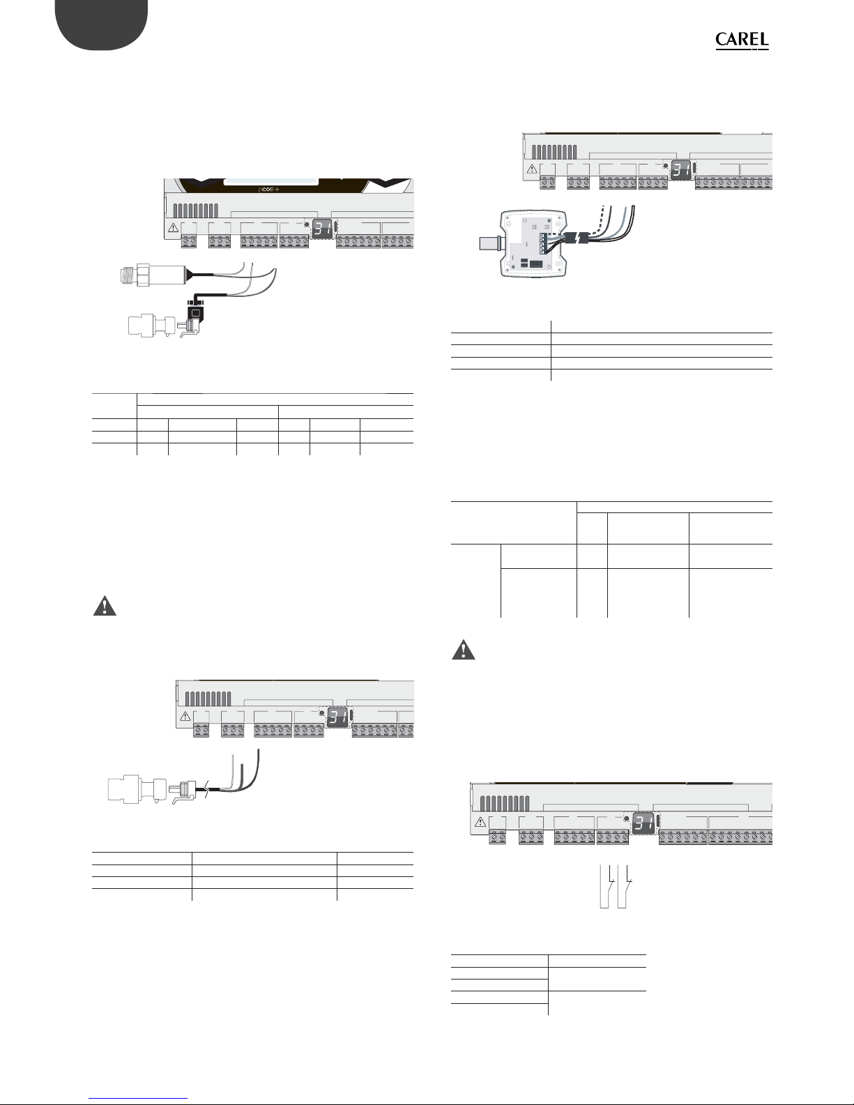
28
ENG
pCO5plus +0300020EN rel. 1.2 - 07.11.2013
Connecting current-output pressure probes
For information on the maximum number of probes that can be
connected see the table at the beginning of this paragraph. For details
on the operating range see the data sheets supplied with the probes.
The controller can be connected to all CAREL SPK* series active pressure
probes or any commercially available pressure probes with 0 to 20 mA or
4 to 20 mA signals.
G
G0
U1U2U3
GND
+VDC
+Vterm
GND
+5 VREF
U4
GNDU5GND
VG
VG0Y1Y2Y3Y4
ID1
ID2
ID3
ID4
J1
J24 J2 J3
J4
J
FieldBus card B MS card
U1
U2
U3
GND
+VDC
U4
GND
U5
GND
1
1
2
21
2
Fig. 5.f
Key
Controller
terminals
Current-output pressure probe
12
+VDC
Wire 1
Power Brown
Wire 1
Power Brown
U1
Wire 2
Signal White -
U2
Wire 2
Signal White
Connecting 0 to 5 V ratiometric pressure probes
For information on the maximum number of probes that can be
connected see the table at the beginning of this paragraph. For details
on the operating range see the data sheets supplied with the probes.
The controller can be connected to all CAREL SPKT series active pressure
probes or any commercially available pressure probes with 0 to 5 V
ratiometric signals.
Important:
• the ratiometric probes are powered by the controller through terminal
+5 VREF;
• the ratiometric probes cannot be powered by an external source.
G
G0
U1U2U3
GND
+VDC
+Vterm
GND
+5 VREF
U4
GNDU5GND
VG
VG0Y1Y2Y3Y4
ID1
ID2
J1 J24 J2 J3
J4
FieldBus card BMS card
U1
U2
U3
GND
GND
+5 VREF
+VDC
Fig. 5.g
Key
Controller terminals Description Wire colour
+5 V
REF Power Black
GND Power reference Green
U1 Signal White
Connecting active probes with 0 to 10 V output
For information on the maximum number of probes that can be
connected see the table at the beginning of this paragraph. For details
on the operating range see the data sheets supplied with the probes.
G
G0
U1U2U3
GND
+VDC
+Vterm
GND
+5 VREF
U4
GNDU5GND
VG
VG0Y1Y2Y3Y4
ID1
ID2
ID3
ID4
J1
J24 J2 J3
J4
J
FieldBus card B MS card
U1
U2
U3
GND
+VDC
M
out T
+ (G)
out H
Fig. 5.h
Key
Controller terminals 0 to 10 V active probes
GND Reference
+VDC Power
U1 Signal 1
U2 Signal 2
Max. number of connectable digital inputs
The controller allows the universal inputs/outputs to be confi gured as
non-optically isolated, voltage-free digital inputs. In any case, the inputs
must be connected to a voltage-free contact.
Max. number of digital inputs connectable
to universal inputs/outputs
Type of signal
pCO5+
Small
Medium/ Built-in
driver/ Extralarge
Large
Digital
inputs (not
optically
isolated)
- voltage-free
contacts
58 10
- fast digital
inputs
max 24(max 2 su U1...U5,
max 2 su U6..U8)
6
(max 2 su U1...U5,
max 2 su U6...U8,
2 su U9...U10)
Tab. 5.c
Important: The maximum current allowed on the digital input is
10 mA. Therefore the rating of the external contact must be at least
10 mA.
Connecting the ON/OFF inputs
There is no particular restriction on the maximum number of inputs that
can be connected. For details on the operating range see the Technical
Specifi cations table.
G
G0
U1U2U3
GND
+VDC
+Vterm
GND
+5 VREF
U4
GNDU5GND
VG
VG0Y1Y2Y3Y4
ID1
ID2
ID3
ID4
ID5
ID6
ID7
ID8
J1
J24 J2 J3
J4
J5
FieldBus card B MS card
U4
U5
GND
GND
Fig. 5.i
Key
Controller terminals Description
U4
Digital input 1
GND
U5
Digital input 2
GND
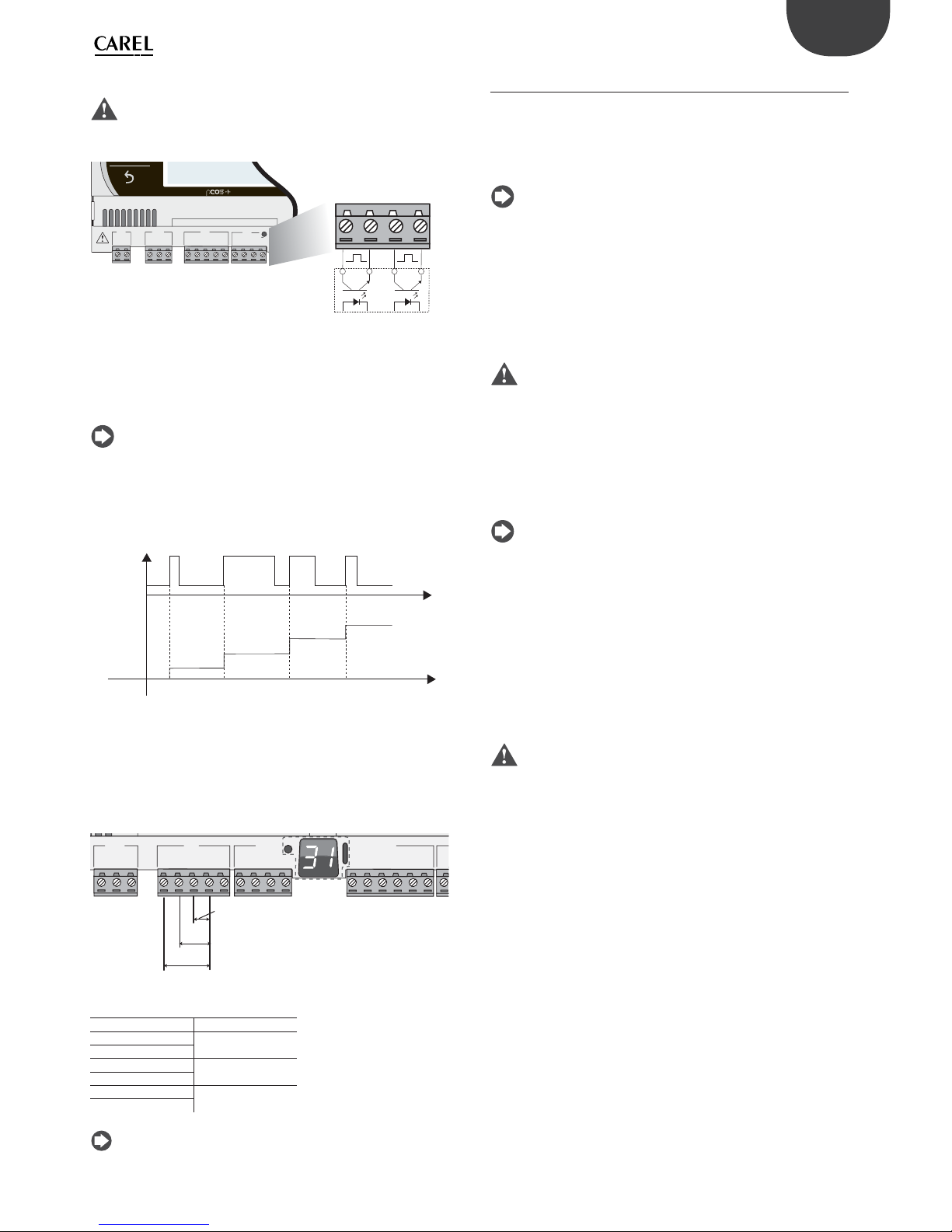
29
ENG
pCO5plus +0300020EN rel. 1.2 - 07.11.2013
Connecting fast digital inputs
Important: The wires connecting the fast digital inputs/counters
must be shielded to avoid causing electromagnetic interference with the
probe cables.
G
G0
U1u2U3
GND
+VDC
+Vterm
GND
+5 VREF
U4
GNDU5GND
J1
J24 J2 J3
FieldBus card
U4
GND
U5
GND
J3
External
impulse
generator
Fig. 5.j
The fast digital input can be used as a frequency meter. The count is
performed on the rising edge of the pulse. The pulse generator device
will have two digital outputs with transistor optocoupler, which will be
connected to the inputs as shown in the fi gure. For details on the input
signal see the Technical Specifi cations table.
Note: The BIOS shows the frequency values using specifi c variables.
If the inputs are confi gured as counters, the application program resets
the counter. The maximum number of pulses is 32767, after which the
counter restarts from zero.
Example:
t
t
input
count
Fig. 5.k
Connecting non-optically-isolated analogue outputs
There is no particular restriction on the number of outputs that can
be connected. For details on the output signal see the Technical
Specifi cations table.
Example: Analogue/PWM outputs connection diagram.
U1U2U3
GND
+VDC
+Vterm
GND
+5 V
REF
U4
GNDU5GND
VG
VG0Y1Y2Y3Y4
ID1
J24 J2 J3
J4
ID1
Vout
Vout
Vout
Fig. 5.l
Key
Controller terminals Description
U1
Analogue output 1
GND
U2
Analogue output 2
GND
U3
Analogue output 3
GND
Note: The analogue outputs cannot be connected in parallel.
5.3 Digital inputs
The controller features digital inputs for connecting safety devices,
alarms, device status indicators and remote switches. These inputs are all
optically isolated from the other terminals. They can work at 24 Vac (+10/15%) or at 28 to 36 Vdc (-20/+10%) (indicated with ID*), and some also at
230 Vac (indicated with IDH*).
Note:
• if the control voltage is drawn in parallel with a coil, install a dedicated
RC fi lter in parallel with the coil (typical ratings are 100 Ω, 0.5 μF, 630 V);
• if the digital inputs are connected to safety systems (alarms), the
presence of voltage across the contact should be taken as the normal
operating condition, while no voltage represents an alarm situation.
This will ensure that any interruption (or disconnection) of the input
will also be signalled;
• do not connect the neutral in place of an open digital input;
• always interrupt the phase.
Important:
• to avoid electromagnetic interference, keep the probe and digital
input cables separated from the power cables as much as possible (at
least 3 cm). Never run power cables and probe signal cables in the
same conduits (including the ones in the electrical panels).
24 Vac digital inputs
The ID... digital inputs can be controlled at 24 Vac.
Note:
• the digital inputs are only functionally isolated from the rest of the
controller;
• if you want to keep the digital inputs optically isolated you will have to
provide a separate power supply for each input;
• the digital inputs can be powered at a diff erent voltage from the rest
of the controller.
Cable section
The cables used for remote connections to the digital inputs should have
the following cross-section:
Cross section for lengths <50 m = 0.25 (mm2)
Important: If the controller is installed in an industrial environment
(standard EN 61000-6-2) the connections must be less than 30 m long. Do
not exceed this length to avoid measurement errors.
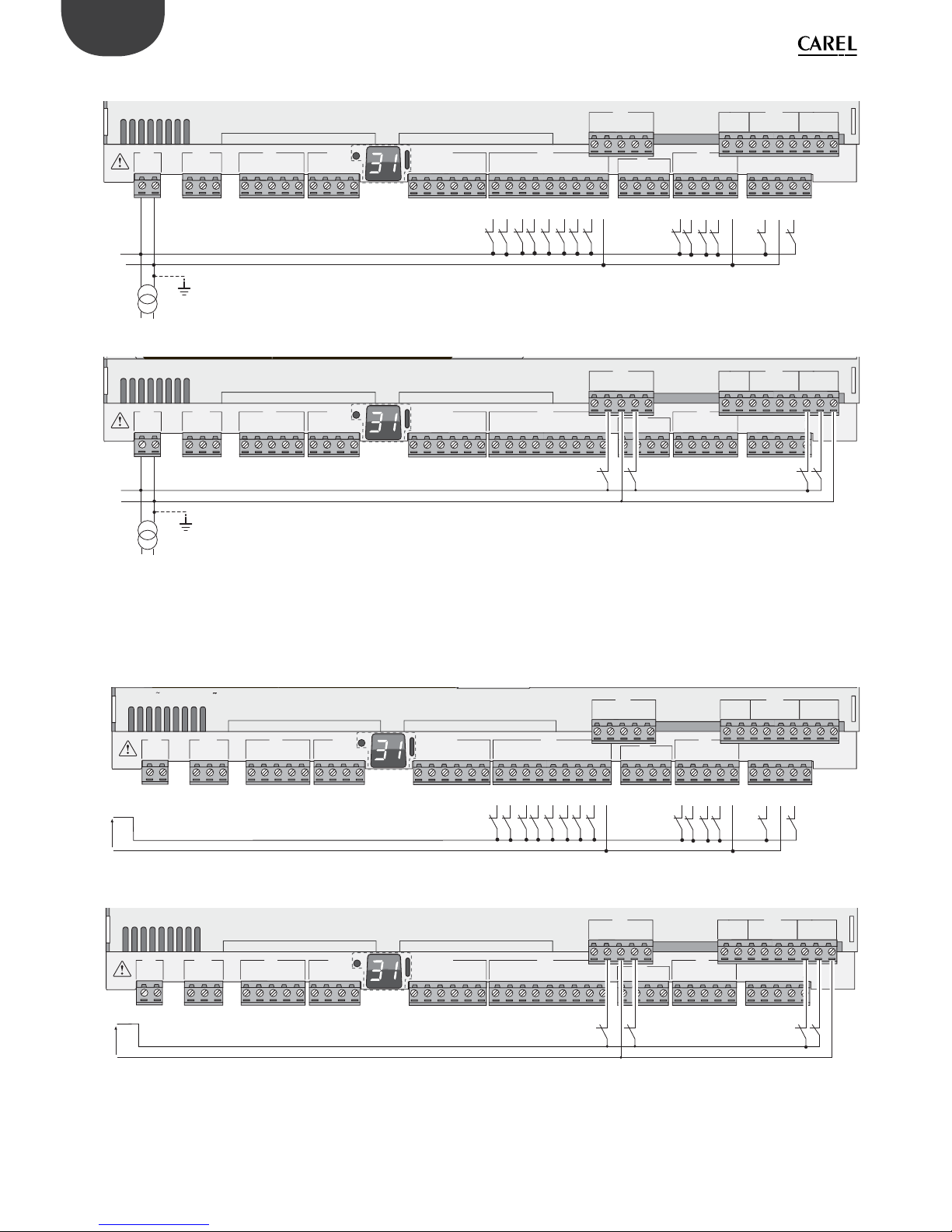
30
ENG
pCO5plus +0300020EN rel. 1.2 - 07.11.2013
Example of connection diagram (LARGE model):
G
G0
U1U2U3
GND
+VDC
+Vterm
GND
+5 VREF
U4
GNDU5GND
VG
VG0Y1Y2Y3Y4
ID1
ID2
ID3
ID4
ID5
ID6
ID7
ID8
IDC1
U6U7U8
GND
ID9
ID10
ID11
ID12
IDC9
ID13H
ID13
IDC13
ID14
ID14H
J1
J24 J2 J3
J4 J5 J7
J8
J20
J6
J19
ID15H
ID15
IDC15
ID16
ID16H
Y5
Y6
ID17
ID18
IDC17
U9
GND
U10
GND
FieldBus card BMS card
G
G0
24 Vac
ID1
ID2
ID3
ID4
ID5
ID6
ID7
ID8
IDC1
ID9
ID10
ID11
ID12
IDC9
ID13H
ID13
IDC13
ID14
ID14H
Fig. 5.m
G
G0
G
G0
U1U2U3
GND
+VDC
+Vterm
GND
+5 VREF
U4
GNDU5GND
VG
VG0Y1Y2Y3Y4
ID1
ID2
ID3
ID4
ID5
ID6
ID7
ID8
IDC1
U6U7U8
GND
ID9
ID10
ID11
ID12
IDC9
ID13H
ID13
IDC13
ID14
ID14H
J1
J24 J2 J3
J4 J5 J7
J8
J20
J6
J19
ID15H
ID15
IDC15
ID16
ID16H
Y5
Y6
ID17
ID18
IDC17
U9
GND
U10
GND
FieldBus card BMS card
24 Vac
Fig. 5.n
24 Vdc digital inputs
The ID... digital inputs can be controlled at 24 Vdc.
Example of connection diagram (LARGE model):
G
G0
U1U2U3
GND
+VDC
+Vterm
GND
+5 VREF
U4
GNDU5GND
VG
VG0Y1Y2Y3Y4
ID1
ID2
ID3
ID4
ID5
ID6
ID7
ID8
IDC1
U6U7U8
GND
ID9
ID10
ID11
ID12
IDC9
ID13H
ID13
IDC13
ID14
ID14H
J1
J24 J2 J3
J4 J5 J7
J8
J20
J6
J19
ID15H
ID15
IDC15
ID16
ID16H
Y5
Y6
ID17
ID18
IDC17
U9
GND
U10
GND
FieldBus card BMS card
input: 24 V 50...60 Hz / 28...36 V
max. power: 45 VA/20 W
-
+
24 Vdc
ID1
ID2
ID3
ID4
ID5
ID6
ID7
ID8
IDC1
ID9
ID10
ID11
ID12
IDC9
ID13H
ID13
IDC13
ID14
ID14H
Fig. 5.o
G
G0
U1U2U3
GND
+VDC
+Vterm
GND
+5 VREF
U4
GNDU5GND
VG
VG0Y1Y2Y3Y4
ID1
ID2
ID3
ID4
ID5
ID6
ID7
ID8
IDC1
U6U7U8
GND
ID9
ID10
ID11
ID12
IDC9
ID13H
ID13
IDC13
ID14
ID14H
J1
J24 J2 J3
J4 J5 J7
J8
J20
J6
J19
ID15H
ID15
IDC15
ID16
ID16H
Y5
Y6
ID17
ID18
IDC17
U9
GND
U10
GND
FieldBus card BMS card
-
+
24 Vdc
Fig. 5.p
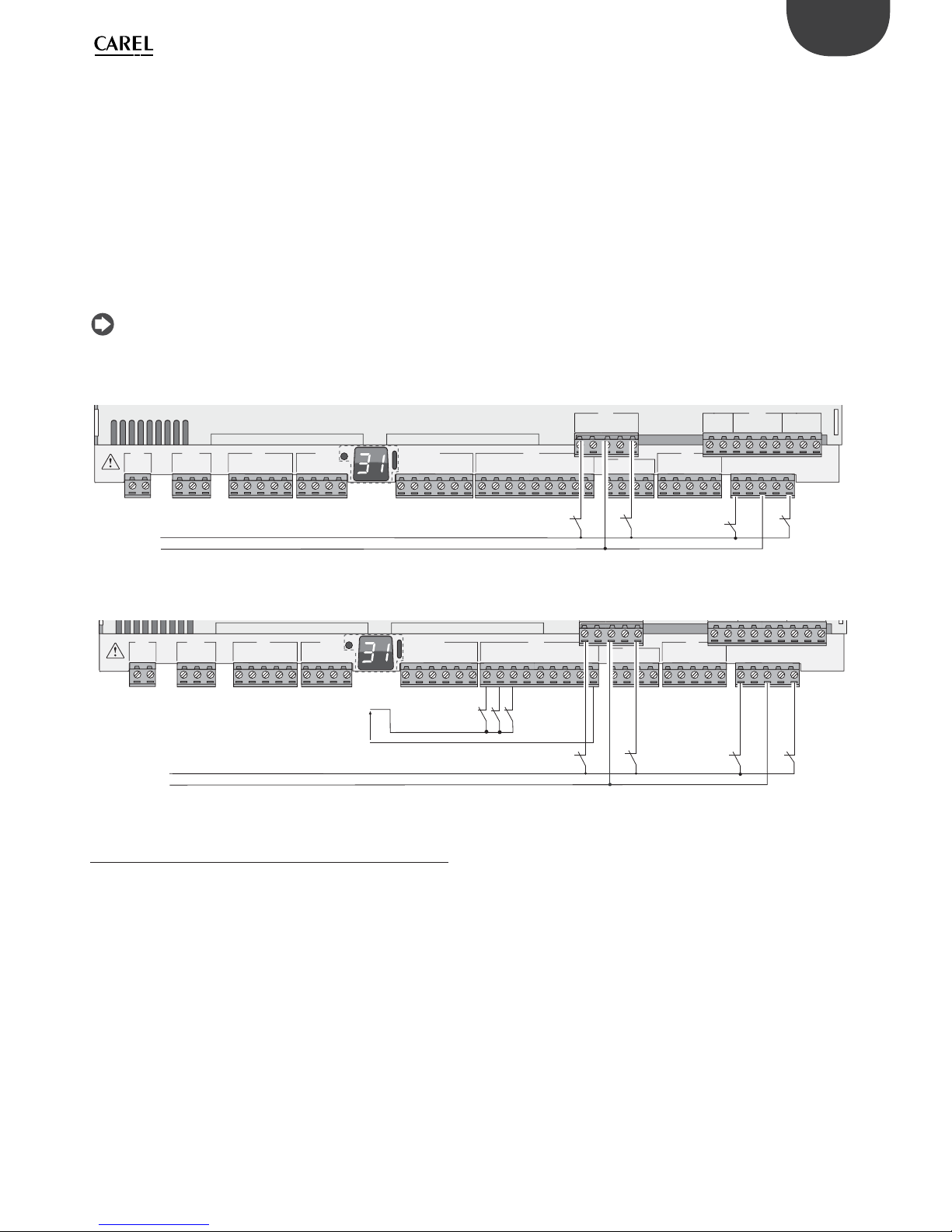
31
ENG
pCO5plus +0300020EN rel. 1.2 - 07.11.2013
230 Vac digital inputs
Medium and Extralarge models feature one group of 230 Vac inputs
(terminal J8), while Large models have two groups (on terminals J8 and
J19). Each group consists of two digital inputs that can be powered at 230
Vac, indicated with IDH*, and two inputs that can be powered at 24 Vac/
Vdc, indicated with ID*.
The two groups of 230 Vac inputs have double insulation between
themselves and between them and the controller. The digital inputs that
are connected can be the 24 Vac/dc inputs of one group and the 230 Vac
inputs of the other.
The two inputs of each group have the same common pole. Operational
insulation is used. In each group, the digital inputs must be powered
at the same voltage (24 Vac, 28 to 36 Vdc or 230 Vac) in order to avoid
dangerous short-circuits and/or the risk of powering lower-voltage
circuits with 230 Vac electricity.
Note:
• the range of uncertainty of the switching threshold is from 43 to 90 Vac;
• the voltage must be 230 Vac (+10/-15%), 50/60 Hz.
Example 1: Connection diagram with inputs at 230 Vac.
G
G0
U1U2U3
GND
+VDC
+Vterm
GND
+5 VREF
U4
GNDU5GND
VG
VG0Y1Y2Y3Y4
ID1
ID2
ID3
ID4
ID5
ID6
ID7
ID8
IDC1
U6U7U8
GND
ID9
ID10
ID11
ID12
IDC9
ID13H
ID13
IDC13
ID14
ID14H
J1
J24 J2 J3
J4 J5 J7
J8
J20
J6
J19
ID15H
ID15
IDC15
ID16
ID16H
Y5
Y6
ID17
ID18
IDC17
U9
GND
U10
GND
FieldBus card BMS card
230 Vac
L
N
Fig. 5.q
Example 2: Connection diagram with digital inputs at diff erent voltages.
G
G0
U1U2U3
GND
+VDC
+Vterm
GND
+5 VREF
U4
GNDU5GND
VG
VG0Y1Y2Y3Y4
ID1
ID2
ID3
ID4
ID5
ID6
ID7
ID8
IDC1
U6U7U8
GND
ID9
ID10
ID11
ID12
IDC9
ID13H
ID13
IDC13
ID14
ID14H
J1
J24 J2 J3
J4 J5 J7
J8
J6
230 Vac
L
N
-
+
24 Vdc
Fig. 5.r
5.4 Optically-isolated analogue outputs
0 to 10 V analogue outputs
On terminals VG and VG0 the controller provides optically-isolated 0 to
10 V analogue outputs, to be powered externally at the same voltage
powering the controller, i.e. 24 Vac or 28 to 36 Vdc. La fi gure below
shows the connection diagram. The 0 V supply voltage is also the voltage
reference of the outputs. See the Technical Specifi cations table for details
on the output current, output impedance, etc.
Note:
• the analogue output can be connected to module code CONVONOFF0
to convert the 0 to 10 V output into an ON/OFF relay output;
• a 0 to 10 Vdc analogue output can be connected in parallel to other
outputs of the same type, or alternatively to an external source of
voltage. The higher voltage will be considered. Correct operation is not
guaranteed if actuators with voltage inputs are connected;
• if optical isolation is not required, the VG-VG0 analogue outputs can be
powered at the same voltage on G-G0: connect G0 to VG0 and G to VG.

32
ENG
pCO5plus +0300020EN rel. 1.2 - 07.11.2013
Example of connection diagram (LARGE model):
GND
+VDC
U4
GNDU5GND
VG
VG0Y1Y2Y3Y4
ID1
ID2
ID3
ID4
ID5
ID6
ID7
ID8
IDC1
U6U7U8
GND
ID9
ID10
ID11
ID12
I DC9
ID13H
ID13
IDC13
ID14
ID14H
J3
J4 J5 J7
J8
J20
J6
J19
ID15H
ID15
IDC15
ID16
ID16H
Y5
Y6
ID17
ID18
IDC17
U9
GND
U10
GND
ldBus card BMS card
4 Vac / 28...36 Vdc
0 V
ID1
ID2
ID3
ID4
ID5
ID6
ID7
ID8
IDC1
ID9
ID10
ID11
ID12
IDC9
ID13H
ID13
IDC13
ID14
ID14H
Vout
Vout
Vout
Vout
Vout
Vout
Fig. 5.s
Max. number di optically-isolated analogue outputs (reference VG0)
pCO5+ model Small/Medium/Extralarge Large
Outputs Y1, Y2, Y3, Y4 Y1, Y2, Y3, Y4, Y5, Y6

33
ENG
pCO5plus +0300020EN rel. 1.2 - 07.11.2013
5.5 Connecting the electronic valve
The controller with a built-in driver can be used to control one or two
electronic expansion valves (depending on the model).
Example of connection diagram (the colour of the wires refers to the
standard CAREL valve cable, code E2VCABS*00).
A
B
CD
C7
NO8
C8
NC8
NO10
J15
J27
132
4
J28
132
4
driver
VBAT
G0
G
J30
GND
VREF
S1S2S3S4DI1
DI2
J29
shield shield
giallo/yellow
bianco/white
verde/green
marrone/brown
NTC driver A
ratiometric pressure
transducer driver A
NTC driver B
ratiometric pressure
transducer driver B
digital input to start the
regulation of driver A
digital input to start the
regulation of driver B
CAREL ExV
valve
A
CAREL
E
x
V valve B
Fig. 5.t
Notes:
• connect the valve cable shield to the blade (faston) connector and
then earth;
• for information on the compatibility of valves and refrigerants, see the
Technical Specifi cations table and the EVD Evolution driver manual.
Apply the Ultracap module (accessory code PCOS0WUC20) on the
controller with built-in valve driver. The module is made with special
capacitors called ultracapacitors that close the electronic valve in case of
power failures. The module only powers the driver and not the controller
it is applied to.
Important: The pCO5+ with built-in driver and PCOS0WUC20
module (or EVD0000UC0 external Ultracap module and EVBAT00400
battery) must be powered at 24 Vac so that emergency valve closing is
ensured in case of power failures. If the controller is powered with DC
voltage it will not close the valve in case of power failures.
Notes:
• the built-in driver replicates all the hardware and logic functions of the
“EVD Evolution” controller in case of 1 valve and of the “EVD Evolution
TWIN” controller in case of 2 valves. In other words, it independently
controls one or two electronic expansion valves with two-pole
stepper motors. The only diff erence with EVD Evolution is that there
are no output relays. For details on the valve control logic, set-up and
installation, see the EVD Evolution manual (code +0300005IT for single
driver, +0300006IT for double driver);
• as with EVD Evolution, the internal driver on the pCO5+ controller
is available in the CAREL and the “Universal” versions. “Universal”
models are used to control both CAREL electronic expansion valves
and products made by other manufacturers (see the Technical
Specifi cations table), while CAREL models only control CAREL valves.
Serial communication and programming
Communication between the pCO5+ and its built-in driver is managed
internally through the FBus2 serial port. The FBus2 serial port (J26) is
however electrically isolated from the driver’s serial line; this ensures that
in case of external faults on the line connected to FBus2, the internal driver
can keep on working independently. The driver can only be confi gured
using the pCO5+ application developed with 1Tool; no external displays
are available for the driver.
The 1Tool development environment features a module for managing
the EVD Evolution driver. When managing the internal driver, use the
module as if you were managing an external driver connected to the
FBus2 port.
At the 1Tool application software level, the valve driver must be
connected to the FBus2 port. Consequently, any other devices physically
connected to the Fbus2 port (J26) must have the same communication
protocol (CAREL Standard Master or Modbus® Master), the same baud
rate, stop bits and parity. The CAREL or Modbus protocol is selected
automatically. The internal driver’s address is 198 (EVD Evolution’s default
address), so any other devices connected to J26 must have an address
other than 198. The CAREL or Modbus protocol is selected automatically.
External EVD Evolution drivers can be connected to the Fieldbus1 serial
port (optional card) with no address restrictions.
C1
NO1
NO2
A
B
CD
C1
C4
NO4
NO5
NO6
C4
C7
NO7C7NO8
C8
NC8
NO12
C12
NC12
NO13
C13
NC13
C9
NO9
NO10
NO11
C9
G
G0
U1U2U3
GND
+VDC
+V
term
GND
+5 V
REF
U4
GNDU5GND
VG
VG0Y1Y2Y3Y4
ID1
ID2
ID3
ID4
ID5
ID6
ID7
ID8
IDC1
U6U7U8
GND
ID9
ID10
ID11
ID12
IDC9
ID13H
ID13
IDC13
ID14
ID14H
FieldBus card
BMS card
CANL
CANH
GND
J26 FBus2
OFF
432 1
ON
132
4
132
4
driver
VBAT
G0
G
GND
VREF
S1S2S3S4DI1
DI2
VBAT
G0
G
EXV connectionPower Supply Relay
NO 1
COM 1
4231
GND
V REFS1S2S3S4
DI1
DI2
Analog – Digital Input Network
GND Tx/Rx
VBAT
G0
G
EXV connectionPower Supply Relay
NO 1
COM 1
4231
GND
V REFS1S2S3S4
DI1
DI2
Analog – Digital Input Network
GND Tx/Rx
VBAT
G0
G
EXV connectionPower Supply Relay
NO 1
COM 1
4231
GND
V REFS1S2S3S4
DI1
DI2
Analog – Digital Input Network
GND Tx/Rx
VBAT
G0
G
EXV connectionPower Supply Relay
NO 1
COM 1
4231
GND
V REFS1S2S3S4
DI1
DI2
Analog – Digital Input Network
GND Tx/Rx
VBAT
G0
G
EXV connectionPower Supply Relay
NO 1
COM 1
4231
GND
V REFS1S2S3S4
DI1
DI2
Analog – Digital Input Network
GND Tx/Rx
VBAT
G0
G
EXV connectionPower Supply Relay
NO 1
COM 1
4231
GND
V REFS1S2S3S4
DI1
DI2
Analog – Digital Input Network
GND Tx/Rx
ADDR≠198
ADDR≠198
ADDR≠198
ADDR =198
ADDR =198
Important: To ensure effi cient data exchange between the driver
and the controller, when developing the 1Tool application, if there are
devices connected to the FBus2 port (terminal J26) using the Modbus®
protocol, developers should take into account the number of variables
exchanged over the entire serial line.

34
ENG
pCO5plus +0300020EN rel. 1.2 - 07.11.2013
5.6 Digital outputs
Electromechanical relay digital outputs
The controller features digital outputs with electromechanical relays. For
ease of installation, the common terminals of some of the relays have
been grouped together.
The type of insulation is described in the table below. See also the
Technical Specifi cations table.
Type of insulation
Between relays in the same group operational insulation
Between groups of relays reinforced insulation
Between relays and the rest of the
controller
reinforced insulation
Notes:
• inside each group, the relays have just operational insulation and must
therefore have the same voltage (generally 24 Vac or 110/230 Vac);
• between groups there is reinforced insulation, so diff erent groups can
have diff erent voltages.
Example of connection diagram (LARGE model):
C1
NO1
NO2
NO3
C1
C4
NO4
NO5
NO6
C4
C7
NO7C7NO8
C8
NC8
NO12
C12
NC12
NO13
C13
NC13
C9
NO9
NO10
NO11
C9
J21
J14
J13
J12
J22
J16
J17
J18
J15
NO14
C14
NC14
NO15
C15
NC15
C16
NO16
NO17
NO18
C16
J23 FBus2
J25
BMS2
J26
FBus2
43 21
N
L
110/230-24Vac
Fig. 5.u
C
4
NO4
NO5
NO6
C4
C7
NO7C7NO8
C8
NC8
NO12
C12
NC12
NO13
C13
NC13
C9
NO9
NO10
NO11
C9
J21
J14
J13
J22
J16
J17
J18
J15
NO14
C14
NC14
NO15
C15
NC15
C16
NO16
NO17
NO18
C16
J23 FBus2
2
J26
FBus2
43 2 1
N
L
110/230-24Vac
Fig. 5.v
Important: The current on the common terminals must not
exceed the capacity (rated current) of each single terminal (8A).
Some relays have change-over contacts.
Relays with change-over contacts
pCO5+ model
Small Medium / Extralarge Large
Output No. 8 8, 12, 13 8, 12, 13
Remote connection of digital outputs
The table below shows the cable sizes required according to the current.
Cross-section (mm2)/AWG Current (A)
0,5/20 2
1,5/15 6
2,5/14 8
Note: When diff erent relay outputs must be operated consecutively
at very close intervals (e.g. star-delta motor starter) in the order of
hundreds of ms, use relays belonging to the same group, according to
the following table.
RELAY GROUPS FOR CONSECUTIVE COMMANDS (~100 ms)
12 3
4 pCO5+
Large
4 pCO5+ ExtraLarge
5
Relè 1, 2, 3, 4 5, 6, 7, 8
9, 10, 11,
12, 13
14, 15, 16,
17, 18
14, 15, 16, 17,
18, 19, 20, 21
22, 23, 24, 25,
26, 27, 28, 29
Tab. 5.d
Important: Using relays that belong to diff erent groups can cause
delays in switching.
5.7 Solid state relay (SSR) digital outputs
pCO5+ controllers are also available in versions with solid-state relays
(SSR) for controlling devices that require an unlimited number of
switching cycles that would not be supported by electromechanical
relays. These outputs are dedicated to resistive loads powered at 224Vac
SELV or 28 to 36 Vdc SELV with max. load current up to 1A or 230 Vac with
max. load current up to 70mA.
Example 1: Connection diagram for resistive load.
NO1
NO2
NO3C1C4
NO4
NO5
NO6C4C7
NO7C7NO8C8NC8
24 Vac/Vdc
Fig. 5.w
Example 2: Connection diagram for inductive or resistive loads, with max.
load current <1 A.
NO5
NO6C4C7
NO7C7NO8C8NC8
24 Vac/Vdc(*)
SSR ESTERNO/
EXTERNAL SSR
carico/load
input
Fig. 5.x
(*) Dedicated power supply or same power supply as controller: not in
common with the power supply for other external loads (e.g. contactors,
coils).
Important: In applications with SSR outputs:
1. the controller should drive only resistive loads with loads current less
than maximum declared;
2. use an additional external SSR to drive inductive loads;
3. for AC power supply to resistive loads or external SSRs,
4. use the same power supply as the controller (connected to terminals
G/G0), which must be dedicated and not in common with the power
supply to other devices in the electrical panel (contactors, coils, etc.)
Note: The SSR load is powered at 24 Vac SELV, 28 to 36 Vdc SELV or
230 Vac; consequently all the other terminals in the group must be
powered at the same voltage due to the absence of reinforced insulation
within the group.

35
ENG
pCO5plus +0300020EN rel. 1.2 - 07.11.2013
5.8 General connection diagram
230/24 Vac
M
OUT
+V
analog output 1 (0...10 Vdc)
analog output 2 (0...10 Vdc)
analog output 3 (0...10 Vdc)
analog output 4 (0...10 Vdc)
analog output 5 (0...10 Vdc)
L
N
digital output 1
digital output 2
digital output 3
digital output 4
digital input 1
digital input 2
digital input 3
digital input 4
digital input 5
digital input 6
digital input 7
digital input 8
digital input 15
digital input 16
digital input 17
digital input 18
digital output 5
digital output 6
digital output 7
digital output 8
digital output 14
digital output 15
digital output 16
digital output 17
digital output 18
probe 9 CAREL NTC
probe 10
voltage-free
digital input
analog output 6 (0...10 Vdc)
G
G0
B1
B2
B3
GND
GND
B4
BC4
B5
BC5
VG0
Y1
Y2
Y3
Y4
ID1
ID2
ID3
ID4
ID5
ID6
ID7
ID8
IDC1
out H
M
NTC
NTC
+ (G)
digital input 9
CP
digital input 10
digital input 11
digital input 12
digital input 13
digital input 14
digital output 9
digital output 10
digital output 11
digital output 12
digital output 13
probe 8 CAREL NTC
probe 6 - 7
SMALL MEDIUM
LARGE
50VA
2.5 AT
C1
NO1
NO2
NO3
C1
C4
NO4
NO5
NO6
C4
C7
NO7
C7
NO8
C8
NC8
G
G0
U1
U2
U3
GND
+VDC
+Vterm
GND
+5 VREF
U4
GND
U5
GND
VG
VG0
Y1
Y2
Y3
Y4
ID1
ID2
ID3
ID4
ID5
ID6
ID7
ID8
IDC1
J1
J24 J2 J3
J4 J5
J14
J10
J13
J12
J15
FieldBus card BMS card
J11 pLAN
J25
BMS2
J26
FBus2
43 2 1
NO12
C12
NC12
NO13
C13
NC13
C9
NO9
NO10
NO11
C9
IDC1
U6
U7
U8
GND
ID9
ID10
ID11
ID12
IDC9
ID13H
ID13
IDC13
ID14
ID14H
J7
J8
J16
J17
J18
J6
J20
J21
J22
J19
NO14
C14
NC14
NO15
C15
NC15
C16
NO16
NO17
NO18
C16
ID15H
ID15
IDC15
ID16
ID16H
Y5
Y6
ID17
ID18
IDC17
U9
GND
U10
GND
J23 F
Bus2
probe 1 (0/5 V)
probe 2 (4/20 mA)
probe 3 (0/1 Vdc or 4/20 mA)
probe 4 Carel NTC
probe 5 PT1000
Fig. 5.y
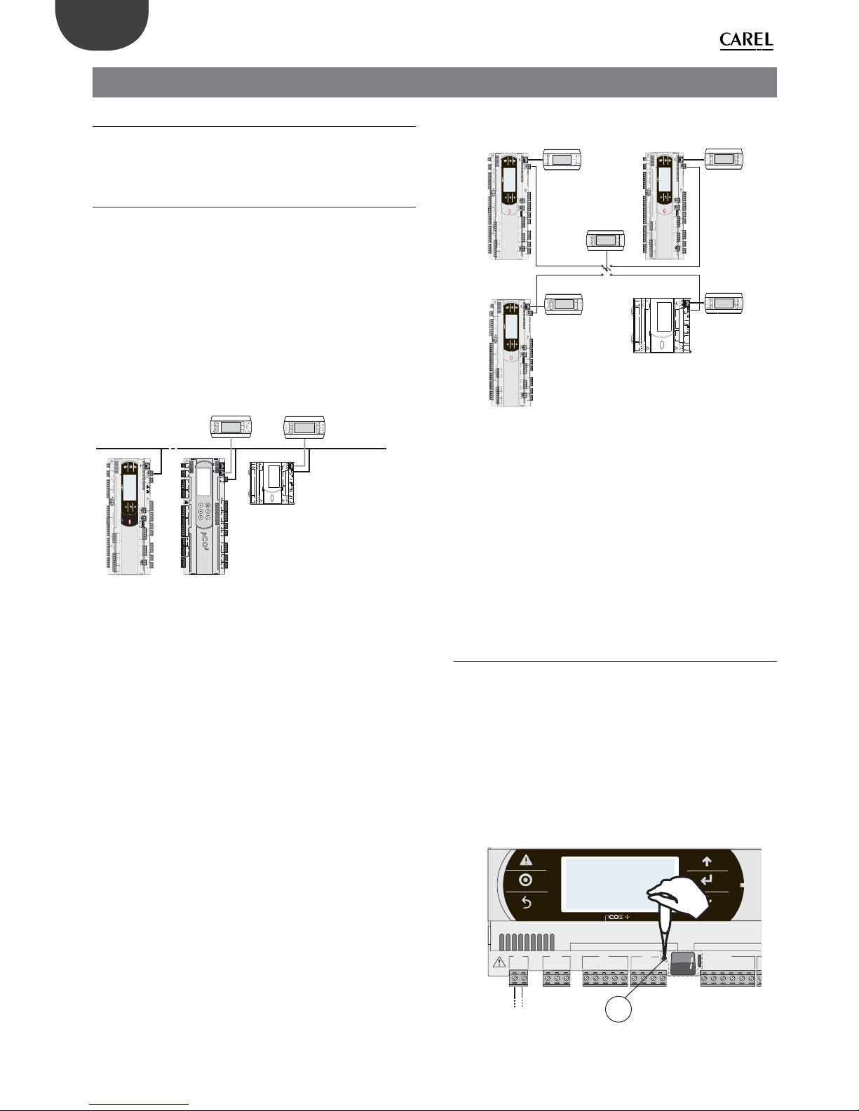
36
ENG
pCO5plus +0300020EN rel. 1.2 - 07.11.2013
6. STARTUP
6.1 Switch-on
When the controller is switched on it runs a test on the secondary display,
lighting up the segments one by one.
6.2 Private and shared terminals
All pCO5+ controllers can be connected to each other and to other
CAREL devices in a pCO local area network (pLAN) without requiring
optional devices, allowing the communication of data and information
from one location (node) to another. The terminals can show the
variables (temperature, humidity, pressure, I/O, alarms) from just one
controller at a time. The terminal does not need to be connected to the
controller during normal operation, but can be used just for the initial
programming of the main parameters. If one or more terminals are
disconnected or malfunctioning, the application program continues to
work correctly on each controller. Generally, the application program can
monitor the status of the network and intervene as necessary to ensure
the continuity of control functions. The fi gure below shows a possible
pLAN network connection diagram.
service card
Rx-/Tx-
Rx+/Tx+
GND
C1
NO1
NO2
NO3
C1
C4
NO4
NO5
NO6
C4
C7
NO7
C7
NO8
C8
NC8
NO12
C12
NC12
NO13
C13
NC13
C9
NO9
NO10
NO11
C9
G
G0
+V
term
GND
+5 V
REF
B4
BC4
B5
BC5
VG
VG0
Y1
Y2
Y3
Y4
B6
B7
B8
GND
J1 J24 J2 J3
J4
J5
J7
J8
J14
J11
J10J9
J13J12
J16 J17
J18J15
J6
drac lairesdrac
dleif
input: 24 V / ; 50 to 60 Hz
max. power: 40 VA/15W
pGDE/pGD1
pGDE/pGD1
pLAN (RS485 62.5 kbit)
pCO5 compact:
ADDR= N
pCO5+: ADDR=1
pCO3: ADDR=2
J7
J10J9
J8
J5
J1
G
G0
+5Vref
+VDC
ID1
GND
J3
C1
NC1
NO1
J2
SYNC
B1
B2
B3
GND
serial card 1
J4
J6
TLAN
GND
C2
NO2
GND
Y2
Y1
GNX
ISOLATED
Tx/Rx
PWM0/10V
GNDTx/Rx
J12
GND
ID2
B7
B8
J11
NO4
NO5
NO6
NO7
C3
NO3
C3
24 V (+10/-15%); 50/60 Hz
48 V (36Vmin…72 Vmax)
input voltage: max. powe r:
14 VA /11 W
C1
NO1
NO2
NO3
C1
C4
NO4
NO5
NO6
C4
C7
NO7
C7
NO8
C8
NC8
NO12
C12
NC12
NO13
C13
NC13
C9
NO9
NO10
NO11
C9
G
G0
U1
U2
U3
GND
+VDC
+Vterm
GND
+5 VREF
U4
GND
U5
GND
VG
VG0
Y1
Y2
Y3
Y4
ID1
ID2
ID3
ID4
ID5
ID6
ID7
ID8
IDC1
U6
U7
U8
GND
ID9
ID10
ID11
ID12
IDC9
ID13H
ID13
IDC13
ID14
ID14H
J1 J24 J2 J3
J4 J5 J7
J8
J20
J21
J14
J10
J13
J12
J22
J16 J17
J18
J15
J6
J19
NO14
C14
NC14
NO15
C15
NC15
C16
NO16
NO17
NO18
C16
ID15H
ID15
IDC15
ID16
ID16H
Y5
Y6
ID17
ID18
IDC17
U9
GND
U10
GND
FieldBus card BMS card
J23 F
Bus2
input: 24 V 50...60
Hz
/ 28...36 V
max. power: 45 VA/20 W
J11 pLAN
J31
CANL
CANH
GND
J25
BMS2
J26
FBus2
OFF
4321
ON
Fig. 6.a
All the terminals and controllers in the network must communicate at the
same speed. The speed is adjusted automatically.
A maximum of 32 units can be connected, including:
• pCO controllers, which run the control program;
• external modules, which provide extended functionality (such as the
EVD Evolution driver);
• terminals.
Every device belonging to a pLAN network is identifi ed by an address,
i.e. a number from 1 to 32. The number 32 can be assigned only to a
terminal. Programs for diff erent applications (e.g. chillers, air-conditioners,
compressor racks, etc.) cannot be automatically integrated into a local
network – they must be confi gured according to the system’s architecture
using the CAREL development tool.
Each controller connected to the network can simultaneously manage
up to 3 terminals in the pLAN network. The values are displayed on the
terminals at the same time and not independently, as if the keypads and
the displays were connected in parallel. Because of that, the controller
cannot drive diff erent kinds of terminals at the same time.
Each terminal associated with a certain controller is defi ned as:
- private (“Pr”) if it displays only the output of that controller;
- shared (“Sh”) if either automatically or from the keypad it can be switched
between various controllers.
Each pCO constantly updates the displays on the private terminals, while
the shared terminals (if present) are updated only by the pCO that is
controlling the terminal at that time.
The fi gure below illustrates the logic of the relations.
J7
J10J9J8J5
J1
G
G0
+5Vref
+VDC
ID1
GND
J3
C1
NC1
NO1
J2
SYNC
B1
B2
B3
GND
serial card 1
J4
J6
TLAN
GND
C2
NO2
GND
Y2
Y1
GNX
ISOLATED
Tx/Rx
PWM0/10V
GNDTx/Rx
J12
GND
ID2
B7
B8
J11
NO4
NO5
NO6
NO7
C3
NO3
C3
24 V (+10/-15%); 50/60 Hz
48 V (36Vmin…72 Vmax)
input voltage: max. pow er:
14 VA /11 W
C1
NO1
NO2
NO3
C1
C4
NO4
NO5
NO6
C4
C7
NO7
C7
NO8
C8
NC8
NO12
C12
NC12
NO13
C13
NC13
C9
NO9
NO10
NO11
C9
G
G0
U1
U2
U3
GND
+VDC
+Vterm
GND
+5 VREF
U4
GND
U5
GND
VG
VG0
Y1
Y2
Y3
Y4
ID1
ID2
ID3
ID4
ID5
ID6
ID7
ID8
IDC1
U6
U7
U8
GND
ID9
ID10
ID11
ID12
IDC9
ID13H
ID13
IDC13
ID14
ID14H
J1 J24 J2 J3
J4 J5 J7
J8
J20
J2
1
J14
J10
J13J12
J22
J16
J17
J18J15
J6
J19
NO14
C14
NC14
NO15
C15
NC15
C16
NO16
NO17
NO18
C16
ID15H
ID15
IDC15
ID16
ID16H
Y5
Y6
ID17
ID18
IDC17
U9
GND
U10
GND
FieldBus card BMS card
J23 F
Bus2
input: 24 V 50...60
Hz / 28...36 V
max. power: 45 VA/20 W
J11 pLAN
J25
BMS2
J26
FBus2
4321
C1
NO1
NO2
NO3
C1
C4
NO4
NO5
NO6
C4
C7
NO7
C7
NO8
C8
NC8
NO12
C12
NC12
NO13
C13
NC13
C9
NO9
NO10
NO11
C9
G
G0
U1
U2
U3
GND
+VDC
+Vterm
GND
+5 VREF
U4
GND
U5
GND
VG
VG0
Y1
Y2
Y3
Y4
ID1
ID2
ID3
ID4
ID5
ID6
ID7
ID8
IDC1
U6
U7
U8
GND
ID9
ID10
ID11
ID12
IDC9
ID13H
ID13
IDC13
ID14
ID14H
J1 J24 J2 J3
J4 J5 J7
J8
J20
J2
1
J14
J10
J13J12
J22
J16
J17
J18
J15
J6
J19
NO14
C14
NC14
NO15
C15
NC15
C16
NO16
NO17
NO18
C16
ID15H
ID15
IDC15
ID16
ID16H
Y5
Y6
ID17
ID18
IDC17
U9
GND
U10
GND
FieldBus card BMS card
J23 F
Bus2
input: 24 V 50...60
Hz / 28...36 V
max. power: 45 VA/20 W
J11 pLAN
J25
BMS2
J26
FBus2
4321
C1
NO1
NO2
NO3
C1
C4
NO4
NO5
NO6
C4
C7
NO7
C7
NO8
C8
NC8
NO12
C12
NC12
NO13
C13
NC13
C9
NO9
NO10
NO11
C9
G
G0
U1
U2
U3
GND
+VDC
+Vterm
GND
+5 VREF
U4
GND
U5
GND
VG
VG0
Y1
Y2
Y3
Y4
ID1
ID2
ID3
ID4
ID5
ID6
ID7
ID8
IDC1
U6
U7
U8
GND
ID9
ID10
ID11
ID12
IDC9
ID13H
ID13
IDC13
ID14
ID14H
J1 J24 J2 J3
J4 J5 J7
J8
J20
J2
1
J14
J10
J13J12
J22
J16 J17
J18
J15
J6
J19
NO14
C14
NC14
NO15
C15
NC15
C16
NO16
NO17
NO18
C16
ID15H
ID15
IDC15
ID16
ID16H
Y5
Y6
ID17
ID18
IDC17
U9
GND
U10
GND
FieldBus card BMS card
J23 F
Bus2
input: 24 V 50...60 Hz / 28...36 V
max. power: 45 VA/20 W
J11 pLAN
J25
BMS2
J26
FBus2
4321
pCO5+: 4
pCO5+: 1
pGDE Private
pGDE Private
pGDE Private
pCO5 compact: 3
pGDE Private
pGDE/pGD1 Shared
1342
pCO5+: 2
Fig. 6.b
In this example the shared terminal is associated with 4 pCO controllers,
but at this instant only controller 1 can display data and receive commands
from the keypad. Switching between controllers occurs in sequence (1>2->3->4->1...) by pressing a button defi ned by the application program;
however it can also be done automatically when requested by the
program. For example, a pCO may request control of the shared terminal
to display alarms or, vice-versa, relinquish control to the next pCO after a
set time (cyclical rotation).
Data on the number and type of terminals is determined during initial
network confi guration and saved in the permanent memory of each pCO
controller. Details of the confi guration procedure are described below.
See the “Installation” chapter for information on the cables to use for the
electrical connections.
6.3 Setting the controller’s address
The controller’s pLAN address is factory-set as 1.
There are two ways to set a controller’s address:
1. using the A button (see fi gure below) located on the left of the
7-segment display. It can be accessed using the tip of a screwdriver
(ø<3 mm);
2. using a terminal connected to the pLAN network.
1. Displaying the pLAN address
Procedure:
• briefl y press the A button (no more than 5 s) to display the controller’s
current pLAN address. Five seconds after releasing the button the
display is cleared.
A
G
G0
U1u2U3
GND
+VDC
+V
term
GND
+5 V
REF
U4
GNDU5GND
VG
VG0Y1Y2Y3Y4
ID1
J1
J24 J2 J3
J4
FieldBus card B MS car
d
FB
Fig. 6.c

37
ENG
pCO5plus +0300020EN rel. 1.2 - 07.11.2013
Setting the pLAN address
Procedure:
1. Press button A for 5 seconds; the pLAN address starts fl ashing.
2. Press repeatedly or hold the button until reaching the desired
address (e.g. 7), then remove the screwdriver.
3. Wait until the address starts fl ashing quickly. The address is now
saved but is not yet active for the application program.
4. Power off the controller.
5. Power on the controller. The address is now active.
G
G0
U1u2U3
GND
+VDC
+V
term
GND
+5 V
REF
U4
GNDU5GND
VG
VG0Y1Y2Y3Y4
ID1
J1
J24 J2 J3
J4
FieldBus card BM S car
d
Fig. 6.d
2. Setting the address using an external terminal
The controller is assigned a private (Pr=private) or shared (Sh=shared)
terminal with address 32. The external terminal can be given an address
from 0 to 32. Addresses between 1 and 32 are used by the pLAN protocol,
while address 0 identifi es the Local Terminal protocol, used for point-topoint connections and to confi gure the controller (this can be done with
a single pGD terminal and a single pCO).
If the controller with default setting (address=1) is connected to an
external terminal (address=32), communication is established and the
external terminal replicates the display on the built-in terminal, if featured.
If however the controller has a diff erent address (e.g. 7) and the terminal
is not set to communicate with the controller at this address, once the
connection is established the terminal will display a blank screen.
In this case, proceed as follows.
Procedure:
1. Press the UP, DOWN and Enter buttons together to go to the screen
for setting the terminal address.
Display address
setting......................................:02
I/O Board address.................:07
Fig. 6.e
2. Set the display’s address to 0 to set the point-to-point connection.
Press Enter to confi rm.
Display address
setting..........:00
Fig. 6.f
3. Power off the controller.
C1
NO1
NO2
NO3
C1
C4
NO4
NO5
NO6
C4
C7
NO7C7NO8
C8
NC8
G
G0
U1u2U3
GND
+VDC
+Vterm
GND
+5 VREF
U4
GNDU5GND
VG
VG0Y1Y2Y3Y4
ID1
ID2
ID3
ID4
ID5
ID6
ID7
ID8
IDC1
J1
J24 J2 J3
J4
J5
J14
J10
J1
3
J12
J15
FieldBus card BMS card
J11 pLAN
J25
BMS2
J26
FBus2
432 1
Fig. 6.g
4. Power on the controller while pressing the Alarm and Up buttons
together until the following screen appears.
#######################
selftest
please wait...
#######################
Fig. 6.h
5. Using the UP and DOWN buttons, set the controller’s pLAN address
to 7 and press Enter to confi rm.
pLAN address: 7
UP: increase
DOWN: decrease
ENTER: save & exit
Fig. 6.i
6.4 Setting the terminal’s address and
connecting the controller to the
terminal
After setting the controller’s network address (see previous paragraph), to
establish connections between the controller and the terminal you need
to set the terminal’s address.
Procedure:
1. Press the UP, DOWN and Enter buttons together. The screen for
setting the terminal’s address is displayed. Set the address to 2 and
press Enter to confi rm.
Display address
setting..........:02
Fig. 6.j
2. Press the UP, DOWN and Enter buttons together. Press Enter twice and set
the controller’s address: 7. Press Enter to confi rm.
Display address
setting...........:02
I/O Board address:07
Fig. 6.k

38
ENG
pCO5plus +0300020EN rel. 1.2 - 07.11.2013
3. Press Enter to confi rm.
Terminal cong
press ENTER
to continue
Fig. 6.l
4. Set terminal 1 ( Trm1) with address 2 as private (Priv) or shared (Shared)
according to the application and confi rm to exit. The connection is
established after a few seconds.
P:07 Adr Priv/Shared
Trm1 02 Pr
Trm2 None -Trm3 None -- Ok? Yes
Fig. 6.m
5. To add a second terminal repeat steps 1 to 4.
6.5 Uploading software
The following methods can be used to update the fi rmware and acquire
the log fi les on pCO controllers:
• smart Key programming key;
• pCO Manager, a program to install on the PC;
• a pendrive.
If you are using a pendrive, before proceeding you must connect the
terminal to the controller following the instructions in par. 4.5 and then
establish the connection. The terminal can be either private or shared.
Smart key
The PCOS00AKY0 key is an electronic device used to program and service
pCO Sistema controllers. The PCOS00AKY0 key simplifi es data transfer
between the controllers installed and a personal computer by exploiting
the high capacity fl ash memory for storing software applications, BIOS
and variable logs. The pCO is connected directly via the telephone
connector using the cable supplied, while to transfer data to a personal
computer the PCOS00AKC0 USB adapter is required. The device is
powered either by the USB port on the PC or by the controller, therefore
no external power supply is necessary.
USB
cavo telefonico
telephone cable
PCOS00AKC0
SMART
KEY
start
mode
C1
NO1
NO2
NO3
C1
C4
NO4
NO5
NO6
C4
C7
NO7C7NO8
C8
NC8
G
G0
U1u2U3
GND
+VDC
+Vterm
GND
+5 VREF
U4
GNDU5GND
VG
VG0Y1Y2Y3Y4
ID1
ID2
ID3
ID4
ID5
ID6
ID7
ID8
IDC1
J1 J24 J2 J3
J4 J5
J14
J10
J13J12
J15
FieldBus card BMS card
input: 24 V 50...60 Hz / 28...36 V
max. power: 45 VA/20 W
J1
1 pL
AN
J31
CANL
CANH
GND
J25
BMS2
J26
FBus2
connessioni in alternativa
alternative connections
Fig. 6.n
The steps to follow are described in par. 9.1.
pCO Manager
On all pCO Sistema controllers the resident software can be updated
using a PC. For this purpose, CAREL provides the pCO Manager program
and a serial converter with RS485 output to connect to the pCO. pCO
Manager is part of the “1Tool” program suite; it can also be installed by
itself and can be obtained free of charge at http://ksa.carel.com, from the
section “pCO Sistema”-> “pCO_manager”. The fi gure below shows the
connection diagram.
CVSTDUTLF0
POWER SUPPLY
USB-RS485 converter
USB
C1
NO1
NO2
NO3
C1
C4
NO4
NO5
NO6
C4
C7
NO7C7NO8
C8
NC8
G
G0
U1u2GND
+VDC
+Vterm
GND
+5 VREF
U4
GNDU5GND
VG
VG0Y1Y2Y3Y4
ID1
ID2
ID3
ID4
ID5
ID6
ID7
ID8
IDC1
J1
J10
FieldBus card
BMS card
input: 24 V 50...60 Hz / 28...36 V
max. power: 45 VA/20 W
CANL
CANH
GND
OFF
4321
ON
J25
BMS2
CVSTDUMOR0
CVSTDUMOR0
pCO Manager
connessioni in alternativa
alternative connections
CVSTDUMOR0
Fig. 6.o
The controller can be connected directly to the PC via the RS485 serial
port used for the “pLAN” connection or via the BMS or Fieldbus serial port
using the optional RS485 serial card. Lastly, connection can be made
using the slave USB port, if present.
pCO Manager can communicate with all the programmable controllers
of the pCO family. The program can also be used to update and download
to the PC the BOOT, BIOS, application program, confi guration and log fi les
and also to save fi les to the NAND fl ash memory.
As a rule, CAREL advises NOT to update the BOOT; CAREL always loads the
BOOT best suited for the controller’s operation during construction. Only
in very special cases will CAREL ask the user to update the BOOT.
The BIOS can only be updated via the pLAN serial connection. This
procedure causes the controller to switch to low-level operation. In this
operating mode log data cannot be downloaded to the PC. To bring the
controller back to normal communications with pCO Manager, reset
the pCO after successfully loading the BIOS. For further information on
the operation of pCO Manager see the online help inside the program.
Download options are shown in the table below.
LOCAL CONNECTION
Serial
pLAN BMS1/BMS2 FieldBus1 USB slave
Uploading the BOOT YES NO NO NO
Uploading the BIOS YES NO NO YES
Uploading the application
and parameters
YES YES YES YES
Uploading/downloading
log fi les
YES YES YES YES
Uploading/downloading to
NAND fl ash memory
YES NO NO YES
Tab. 6.a
The steps to follow are described in par. 9.2.

39
ENG
pCO5plus +0300020EN rel. 1.2 - 07.11.2013
NAND ash memory
This type di memory is included on all pCO5+ controller versions. pCO
Manager can be used to load any type of fi le to the NAND fl ash memory.
It can be used, for example, to save the source fi les of the application
program being used.
In addition, the IUP, BLB (or BIN) and DEV fi les that represent parameter
fi les, the screens displayed in the various languages and the control
logic can be loaded to the NAND fl ash memory and then selected from
the terminal screen to be used as the current application on the pCO.
Specifi cally, several diff erent applications, or diff erent languages, or
multiple parameter fi les can all be loaded in the NAND fl ash memory,
after which the desired application, language or parameter confi guration
can be selected and loaded to the main fl ash memory. The fi les saved in
the NAND fl ash memory can be selected and copied to the main fl ash
memory on the screen managed directly by the BIOS. The procedure is
described in paragraph 6.6.
Limitations:
• a maximum of 40 fi les can be saved on the NAND fl ash memory;
• the memory’s total storage capacity is 50 MB.
Pendrive
Some controller models come with two diff erent USB ports (host and
slave) to be used for installation and diagnostics. The host port can be
used to connect USB mass storage peripherals (pendrives, portable hard
disks, etc., having a maximum current consumption of 500 mA) with
which to carry out various operations:
1. upload to the controller fi les contained in the removable peripheral
(e.g. application, parameters in the buff er memory, confi guration fi les
for logs, BIOS);
2. download fi les from the pCO5+ to the removable peripheral (e.g.
application, parameters in the buff er memory, data logs, BIOS).
Note: Using the pendrive to perform the following operations:
• UPLOAD - copying fi les from the pendrive to the controller;
• DOWNLOAD - copying fi les from the controller to the pendrive is
possible only when using a terminal, either built-in or connected to
the controller via pLAN.
The controller can be provided with 2 USB ports which can be accessed
by removing the cover (see chap. 2).
The keypad has 6 buttons that, pressed alone or in combination, can be
used to perform all the UPLOAD and DOWNLOAD operations between
the pendrive and the controller.
Important
• before the pendrive can be used it must be formatted to the FAT32
fi le system;
• the pendrive can be accessed up to two levels – APPL\CHILLER\PRI.BIN
– but access to fi le \APPL\CHILLER\VER1\PRI.BIN is not allowed;
• do not use both USB ports at the same time;
• the maximum pendrive capacity supported is 32 GB.
Manual, automatic and autorun mode
• manual mode involves selecting the operations to be performed via
the keypad; this off ers maximum fl exibility and the possibility to freely
decide which operations to perform;
• automatic mode requires creating special fi les called confi guration
fi les. These are text fi les (.txt extension) containing various types of
information on the functions to perform and the fi les to load;
• autorun mode requires creating a special confi guration fi le called
“autorun.txt”. When the pendrive is plugged, in the controller
immediately executes Autorun and upon confi rmation from the
terminal performs the operations contained in the fi le.
Upload and Download
UPLOAD can be performed in three diff erent ways:
1. manual mode: the user selects manual mode from the keypad, then
the fi les to load, and then confi rms to start the operation;
2. automatic mode: the user selects automatic mode from the keypad
and then the confi guration fi les containing the instructions on the
operations to carry out;
3. autorun mode: after the pendrive is plugged in, a screen is displayed
indicating that Autorun mode has started. After confi rming, the
instructions contained in “autorun.txt” are executed automatically.
The contents of this fi le are similar to the UPLOAD confi guration fi les,
the only diff erence being the name “autorun.txt”.
DOWNLOAD can be performed in two diff erent ways:
1. manual mode: the user selects manual mode, then the fi les to
download, and then confi rms to start the operation;
2. autorun mode: after the pendrive is plugged in, a screen is displayed
indicating that Autorun mode has started. After confi rming, the
instructions contained in “autorun.txt” are executed automatically.
The contents of this fi le are similar to the DOWNLOAD confi guration
fi les, the only diff erence being the name “autorun.txt”.
Note: The confi guration and autorun fi les must reside in the main
directory.
The steps to follow are described in par. 9.3.
6.6 Checking the software installed and
other information
Users can at any time check the version of the current program (by CRC
code, expressed in hexadecimal), and also whether it is being used by the
key or by the resident program. To do this, proceed as follows.
Screens managed by BIOS
Press the ALARM and ENTER buttons together for 3 seconds. The following
screen will appear.
>SYSTEM I NFORMATI ON
LOG DATA
OTHE R I NFORM ATI ON
FLASH /USB MEMORY
Each of the four lines displayed is used to access further screens, managed
by BIOS and consequently always available regardless of the application
loaded. To access the functions, select the line with the cursor “>” using
the UP and DOWN buttons and then press ENTER to confi rm. To exit the
screen press MENU or Esc on the terminal, or wait around 40 seconds for
automatic timeout.
The screens provide the following information.
1. SYSTEM INFORMATION: Selecting this function displays
information on the software loaded and the amount of RAM
and fl ash memory installed. The screen displayed is similar to the
following.
BOOT V 4. TE 6/ 12/ 11
BI OS V 6. TE13/01/ 12
>2+ 7 MB <
A_CRC: 0000- 3617 MB
The fi rst line displays the BOOT version and date. In the example shown,
the pCO is working with BOOT 4 dated 6 December 2011. The second
line displays the BIOS version and date. In the example shown, the pCO
is working with BOOT 6 dated 13 January 2012. The fourth line displays
the application CRC and the amount of fl ash memory occupied. In the
example, the application’s CRC value is 3617. If this line shows 1 MB, a pCO
with 1 MB fl ash is suffi cient. The CRC is a number that summarises the
application contained in the pCO’s fl ash memory, but also other system
information. It is therefore recommended to note the version of a specifi c
application by checking the screen on which it is displayed.

40
ENG
pCO5plus +0300020EN rel. 1.2 - 07.11.2013
2. LOG DATA: Selecting this function allows any logged data on
the pCO to be viewed. If no log is present, the following screen is
displayed.
0
NO LOG DATA
PRESS
[MENU] OR [ ESC]
If at least one log is present, the fi rst screen displayed is similar to the
following.
1 DI SPLAY LOG DATA
Wh i ch memo r y ?
INTERNAL MEMORY
Detailed information on the screens relating to the logs is provided in the
pCO Manager manual.
3. OTHER INFORMATION: Selecting this function lets you view the ID
number assigned to the pCO, confi gure the pCOnet/pCOweb cards
and view the status of the buff er memories ( T ), the parameters (P)
and the clock (E).
>ID NUMBER INFO
PCOWEB / NET CONF I G
MEMORI ES STATUS
The ID number is a code, diff erent for each pCO manufactured by CAREL,
and is available for use in future applications. Not all pCO units are given
an ID number by CAREL; if no ID number is available, the following screen
is displayed.
>PCOWEB settings
PCONET set t i ngs
See the Appendix for information on confi guring the PCOnet and
PCOweb cards.
The status of the buff er memories (T ), the parameters (P) and the clock (E)
is displayed as follows. Select a memory to view its status.
>T MEMORY STATUS
PMEMORYSTATUS
EMEMORYSTATUS
4. FLASH/ USB MEMORY: Selecting this string displays the following
screen.
> NAND FLASH F I LES
USB PEN DRI VE
The fi rst selection lets you view the names of the IUP, BLB, GRP and DEV
fi les contained in the NAND memory. You can also copy an application
from the NAND memory to the pCO’s main fl ash memory. Each fi le name
is shown on a screen such as the one below.
[X]
PGD23_ALL.grp
To move from one fi le to another press the UP or DOWN button. Press
ENTER to select the current fi le to copy to the main fl ash memory. The
fi les selected to be copied are marked by an “X” on the fi rst line of their
respective screens. In the example shown, the “PGD23_ALL.grp” fi le is
selected to be copied. To start the copy, press UP or DOWN until the
following screen appears:
Press Enter
to star t copy ing
and then press ENTER to confi rm.
See the pCO Manager manual for further information on using the NAND
memory.
To exit these two screens press Menu on the local terminal or wait around
40 seconds for automatic timeout.
For information on the screens related to the pendrive, see paragraph
9.3. If the pendrive is non connected, the following message is displayed:
No USB d i sk o r PC
connec ted
Press ESC or
insert key/cable

41
ENG
pCO5plus +0300020EN rel. 1.2 - 07.11.2013
7. APPLICATION DIAGRAMS
The following are a series of diagrams illustrating which devices can be
connected to the pCO5+ and the accessory cards required, depending
on the type of application.
Air handling unit
PCOS004850:
scheda seriale RS485
PCO10000F0:
schede LON
S90CONN*:
cavo di
collegamento
sonde seriali
DP****4****
PCO10W0BA0:
scheda interfaccia
BACnet™ RS485
PCO10W0WB0:
pCO Web - sch. interfaccia
Ethernet™/BACnet™
Servocontrollo
della serranda
Valvola di
servocontrollo
PCO100MPB0:
scheda MP-BUS
584SRsutats
GNX RS485
+ –
P1 P2 P3
BACnet™ MS/TP
PGD Touch
PGD1*
CP*: schede controllo
umidificatori KUE*
dispositivi
terze parti
FAN
C1
NO1
NO2
NO3
C1
C4
NO4
NO5
NO6
C4
C7
NO7C7NO8
C8
NC8
NO12
C12
NC12
NO13
C13
NC13
C9
NO9
NO10
NO11
C9
G
G0
U1U2U3
GND
+VDC
+V
term
GND
+5 V
REF
U4
GNDU5GND
VG
VG0Y1Y2Y3Y4
ID1
ID2
ID3
ID4
ID5
ID6
ID7
ID8
IDC1
U6U7U8
GND
ID9
ID10
ID11
ID12
IDC9
ID13H
ID13
IDC13
ID14
ID14H
J1 J24 J2 J3
J4 J5 J7
J8
J20
J21
J14
J10
J1
3
J12
J22
J16 J17
J18
J15
J6
J1
9
NO14
C14
NC14
NO15
C15
NC15
C16
NO16
NO17
NO18
C16
ID15H
ID15
IDC15
ID16
ID16H
Y5
Y6
ID17
ID18
IDC17U9GND
U10
GND
FieldBus card BM S card
J23 FBus2
input: 24 V 50...60 Hz / 28...36 V
max. power: 45 VA/20 W
J11 pLAN
J25
BMS2
J26
FBus2
432 1
Fig. 7.a
Roof-top unit
EEV
PCOS004850:
scheda seriale RS485
PCO10000F0:
schede LON
S90CONN*:
cavo di
collegamento
sonde seriali
DP****4****
PCO10W0BA0:
scheda interfaccia
BACnet™ RS485
PCO10W0WB0:
pCO Web - sch. interfaccia
Ethernet™/BACnet™
Servocontrollo
della serranda
Valvola di
servocontrollo
PCO100MPB0:
scheda MP-BUS
584SRsutats
GNX RS485
+ –
P1 P2 P3
BACnet™ MS/TP
PGD Touch
PGD1*
CP*: schede controllo
umidificatori KUE*
C1
NO1
NO2
NO3
C1
C4
NO4
NO5
NO6
C4
C7
NO7C7NO8
C8
NC8
NO12
C12
NC12
NO13
C13
NC13
C9
NO9
NO10
NO11
C9
G
G0
U1u2U3
GND
+VDC
+Vterm
GND
+5 VREF
U4
GNDU5GND
VG
VG0Y1Y2Y3Y4
ID1
ID2
ID3
ID4
ID5
ID6
ID7
ID8
IDC1
U6U7U8
GND
ID9
ID10
ID11
ID12
IDC9
ID13H
ID13
IDC13
ID14
ID14H
J1
J24 J2 J3
J4 J5 J7
J8
J14
J10
J13
J12
J16
J17
J18
J15
J6
FieldBus card BMS card
input: 24 V 50...60 Hz / 28...36 V
max. power: 45 VA/20 W
J11 pLAN
J25
BMS2
J26
FBus2
OFF
4321
ON
4
2
3
1
J127
GND
VREF
S1
S2
S3
S4
DI1
DI2
J29
VBAT
G0
G
J30
A
B
CD
Power +
PSD0*
Fig. 7.b
Heat pump
S90CONN*:
cavo di
collegamento
sonde seriali
DP****4****
th Tune
AT*
PCO100FD10:
scheda seriale
FieldBus
PGD Touch
EEV
PGD1*
Power +
PSD0*
PCOS004850:
scheda seriale RS485
PCO10000F0:
schede LON
PCO10W0BA0:
scheda interfaccia
BACnet™ RS485
PCO10W0WB0:
pCO Web - sch. interfaccia
Ethernet™/BACnet™
584SRsutats
GNX RS485
+ –
P1 P2 P3
BACnet™ MS/TP
C1
NO1
NO2
NO3
C1
C4
NO4
NO5
NO6
C4
C7
NO7C7NO8
C8
NC8
NO12
C12
NC12
NO13
C13
NC13
C9
NO9
NO10
NO11
C9
G
G0
U1u2U3
GND
+VDC
+Vterm
GND
+5 VREF
U4
GNDU5GND
VG
VG0Y1Y2Y3Y4
ID1
ID2
ID3
ID4
ID5
ID6
ID7
ID8
IDC1
U6U7U8
GND
ID9
ID10
ID11
ID12
IDC9
ID13H
ID13
IDC13
ID14
ID14H
J1
J24 J2 J3
J4 J5 J7
J8
J14
J10
J13
J12
J16
J17
J18
J15
J6
FieldBus card BMS card
input: 24 V 50...60 Hz / 28...36 V
max. power: 45 VA/20 W
J11 pLAN
J25
BMS2
J26
FBus2
432 1
4
2
3
1
J127
GND
VREF
S1
S2
S3
S4
DI1
DI2
J29
VBAT
G0
G
J30
A
B
CD
Fig. 7.c
Close control unit (CCU)
S90CONN*:
cavo di
collegamento
PGD Touch
PGD1*
EEV
Power + PSD0*
schede CP*: controllo
umidificatori KUE*
dispositivi
terze parti
FAN
PCOS004850:
scheda seriale RS485
PCO10000F0:
schede LON
PCO10W0BA0:
scheda interfaccia
BACnet™ RS485
PCO10W0WB0:
pCO Web - sch. interfaccia
Ethernet™/BACnet™
584SRsutats
GNX RS485
+ –
P1 P2 P3
BACnet™ MS/TP
C1
NO1
NO2
NO3
C1
C4
NO4
NO5
NO6
C4
C7
NO7C7NO8
C8
NC8
NO12
C12
NC12
NO13
C13
NC13
C9
NO9
NO10
NO11
C9
G
G0
U1u2U3
GND
+VDC
+Vterm
GND
+5 VREF
U4
GNDU5GND
VG
VG0Y1Y2Y3Y4
ID1
ID2
ID3
ID4
ID5
ID6
ID7
ID8
IDC1
U6U7U8
GND
ID9
ID10
ID11
ID12
IDC9
ID13H
ID13
IDC13
ID14
ID14H
J1 J24 J2 J3
J4
J5 J7
J8
J14
J10
J13
J12
J16
J17
J18
J15
J6
FieldBus card BMS card
J11 pLAN
J25
BMS2
J26
FBus2
4321
423
1
J127
GND
VREF
S1
S2
S3
S4
DI1
DI2
J29
VBAT
G0
G
J30
A
B
CD
Fig. 7.d
Serial probes
DP****4****
Servo-control
valve
Damper
servo-control
RS485 serial card
BACnetTM RS485 interface card
pCO Web - interface card
EthernetTM/BACnet
TM
LON card
Device
CP*: KUE humidifi er
control boards*
S90CONN*:
connection
cable
PCO100MPB0:
MP-BUS card
RS485 serial card
BACnetTM RS485 interface card
pCO Web - interface card
EthernetTM/BACnet
TM
LON card
Servo-control
valve
Damper
servo-control
S90CONN*:
connection
cable
PCO100MPB0:
MP-BUS card
RS485 serial card
BACnetTM RS485 interface card
pCO Web - interface card
EthernetTM/BACnet
TM
LON card
PCO100FD10:
FileBus serial
card
S90CONN*:
connection
cable
DP****4****
serial probes
RS485 serial card
BACnetTM RS485 interface card
pCO Web - interface card
EthernetTM/BACnet
TM
LON card
S90CONN*:
connection
cable
Device
CP*: KUE humidifi er
control boards*
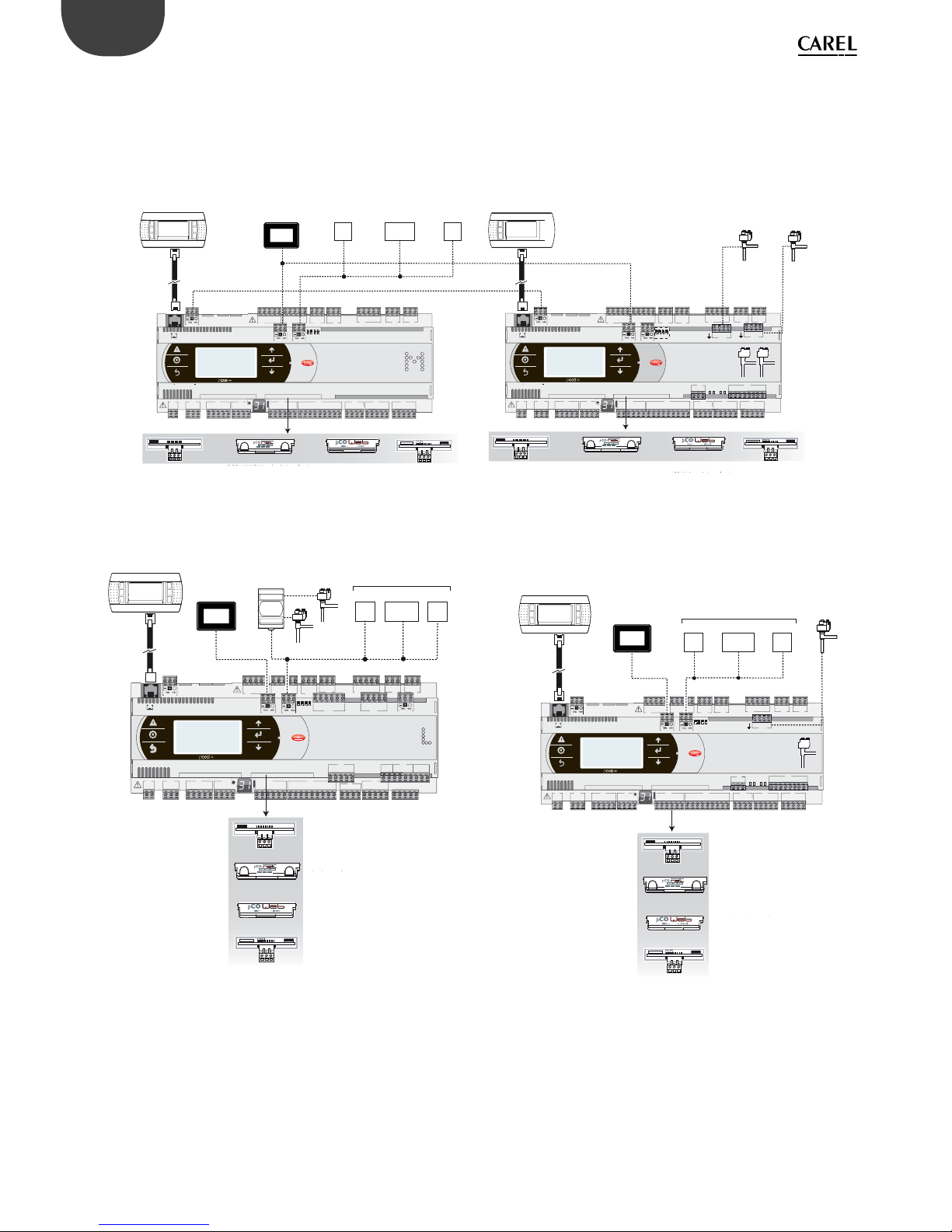
42
ENG
pCO5plus +0300020EN rel. 1.2 - 07.11.2013
Chiller - Screw compressor
To manage two refrigerant circuits, there are two options.
Case 1: 2 pCO5 Medium controllers and pCO5+ with built-in electronic
expansion valve driver.
S90CONN*:
cavo di collegamento
PGD Touch
PGD1*
dispositivi
terze parti
dispositivi
terze parti
dispositivi
terze parti
FAN
PUMP
INVERTER
PGD1*
EEV EEV
PCOS004850:
scheda seriale RS485
PCO10000F0:
schede LON
PCO10W0BA0: scheda interfaccia
BACnet™ RS485
PCO10W0WB0:
pCO Web - sch. interfaccia
Ethernet™/BACnet™
584SRsutats
GNX RS485
+ –
P1 P2 P3
BACnet™ MS/TP
PCOS004850:
scheda seriale RS485
PCO10000F0:
schede LON
PCO10W0BA0: scheda interfaccia
BACnet™ RS485
PCO10W0WB0:
pCO Web - sch. interfaccia
Ethernet™/BACnet™
584SRsutats
GNX RS485
+ –
P1 P2 P3
BACnet™ MS/TP
C1
NO1
NO2
NO3
C1
C4
NO4
NO5
NO6
C4
C7
NO7C7NO8
C8
NC8
NO12
C12
NC12
NO13
C13
NC13
C9
NO9
NO10
NO11
C9
G
G0
U1u2U3
GND
+VDC
+Vterm
GND
+5 VREF
U4
GNDU5GND
VG
VG0Y1Y2Y3Y4
ID1
ID2
ID3
ID4
ID5
ID6
ID7
ID8
IDC1
U6U7U8
GND
ID9
ID10
ID11
ID12
IDC9
ID13H
ID13
IDC13
ID14
ID14H
J1
J24 J2 J3
J4
J5 J7
J8
J14
J10
J13
J12
J16
J17
J18
J15
J6
FieldBus card BMS card
input: 24 V 50...60 Hz / 28...36 V
max. power: 45 VA/20 W
J11 pLAN
J25
BMS2
J26
FBus2
OFF
4321
ON
423
1
J127
423
1
J128
GND
VREF
S1S2S3
S4
DI1
DI2
J29
VBAT
G0
G
J30
A
B
CD
C1
NO1
NO2
NO3
C1
C4
NO4
NO5
NO6
C4
C7
NO7C7NO8
C8
NC8
NO12
C12
NC12
NO13
C13
NC13
C9
NO9
NO10
NO11
C9
G
G0
U1u2U3
GND
+VDC
+Vterm
GND
+5 VREF
U4
GNDU5GND
VG
VG0Y1Y2Y3Y4
ID1
ID2
ID3
ID4
ID5
ID6
ID7
ID8
IDC1
U6U7U8
GND
ID9
ID10
ID11
ID12
IDC9
ID13H
ID13
IDC13
ID14
ID14H
J1
J24 J2 J3
J4
J5 J7
J8
J14
J10
J13J12
J16
J17
J18
J15
J6
FieldBus card BMS card
input: 24 V 50...60 Hz / 28...36 V
max. power: 45 VA/20 W
J11 pLAN
J25
BMS2
J26
FBus2
4321
Case 2: 1 pCO5 Large with external EVD Evolution twin driver.
S90CONN*:
cavo di
ollegamento
PGD Touch
EVD*T*
EVD Evolution twin
EEV
EEV
dispositivi terze parti
FAN
PUMP
INVERTER
PCOS004850:
scheda seriale RS485
PCO10000F0:
schede LON
PCO10W0BA0:
scheda interfaccia
BACnet™ RS485
PCO10W0WB0:
pCO Web - sch. interfaccia
Ethernet™/BACnet™
584SRsutats
GNX RS485
+ –
P1 P2 P3
BACnet™ MS/TP
C1
NO1
NO2
NO3
C1
C4
NO4
NO5
NO6
C4
C7
NO7C7NO8
C8
NC8
NO12
C12
NC12
NO13
C13
NC13
C9
NO9
NO10
NO11
C9
G
G0
U1U2U3
GND
+VDC
+V
term
GND
+5 V
REF
U4
GNDU5GND
VG
VG0Y1Y2Y3Y4
ID1
ID2
ID3
ID4
ID5
ID6
ID7
ID8
IDC1
U6U7U8
GND
ID9
ID10
ID11
ID12
IDC9
ID13H
ID13
IDC13
ID14
ID14H
J1
J24 J2 J3
J4 J5 J7
J8
J20
J21
J14
J10
J1
3
J12
J22
J16 J17
J18
J15
J6
J1
9
NO14
C14
NC14
NO15
C15
NC15
C16
NO16
NO17
NO18
C16
ID15H
ID15
IDC15
ID16
ID16H
Y5Y6ID17
ID18
IDC17U9GND
U10
GND
FieldBus card BMS card
J23 FBus2
J11 pLAN
J25
BMS2
J26
FBus2
432 1
Chiller - Scroll compressor
S90CONN*:
cavo di
collegamento
PGD Touch
EEV
PGD1*
FAN
PUMP
INVERTER
dispositivi terze parti
PCOS004850:
scheda seriale RS485
PCO10000F0:
schede LON
PCO10W0BA0: scheda interfaccia
BACnet™ RS485
PCO10W0WB0:
pCO Web - sch. interfaccia
Ethernet™/BACnet™
584SRsutats
GNX RS485+ –
P1 P2 P3
BACnet™ MS/TP
C1
NO1
NO2
NO3
C1
C4
NO4
NO5
NO6
C4
C7
NO7C7NO8
C8
NC8
NO12
C12
NC12
NO13
C13
NC13
C9
NO9
NO10
NO11
C9
G
G0
U1u2U3
GND
+VDC
+Vterm
GND
+5 VREF
U4
GNDU5GND
VG
VG0Y1Y2Y3Y4
ID1
ID2
ID3
ID4
ID5
ID6
ID7
ID8
IDC1
U6U7U8
GND
ID9
ID10
ID11
ID12
IDC9
ID13H
ID13
IDC13
ID14
ID14H
J1
J24 J2 J3
J4
J5 J7
J8
J14
J10
J13
J12
J16
J17
J18
J15
J6
FieldBus card BMS card
J11 pLAN
J25
BMS2
J26
FBus2
4321
423
1
J127
GND
VREF
S1
S2
S3
S4
DI1
DI2
J29
VBAT
G0
G
J30
A
B
CD
RS485 serial card
PCO1000BA0: BACnetTM RS485
interface card
pCO Web - interface card
EthernetTM/BACnet
TM
LON card
Device
Device
Device
RS485 serial card
PCO1000BA0: BACnetTM RS485
interface card
pCO Web - interface card
EthernetTM/BACnet
TM
LON card
S90CONN*:
connection
cable
Device
S90CONN*:
connection
cable
RS485 serial card
BACnetTM RS485
interface card
pCO Web - interface card
EthernetTM/BACnet
TM
LON card
S90CONN*:
connection
cable
Device
RS485 serial card
BACnetTM RS485
interface card
pCO Web - interface card
EthernetTM/BACnet
TM
LON card

43
ENG
pCO5plus +0300020EN rel. 1.2 - 07.11.2013

44
ENG
pCO5plus +0300020EN rel. 1.2 - 07.11.2013
7.1 Devices that can be connected to the
pCO5+
device serial
ZERO pLAN
serial ONE - BMS1 serial TWO – Fieldbus 1 serial
THREE
- BMS 2
serial
FOUR Fieldbus 2
master (Host)
USB
Connector J11
Connector J10
PCO1004850
PCOS004850
PCO100MDM0
PCO10000F0
PCO10000R0
PCO10W0WB0
PCO10W0BA0
PCOS00HBB0
PCOS00KXB0
PCO100FD10
PCOS00FD20
PCO100TLN0
PCO100MPB0
PCOS00HBF0
Connector J25
Connector J26
(and J23 on L
and XL)
PST terminal x
PLD terminal x
pCOT - pCOI terminal x
pGD0 - pGD1 terminal x
pGD2 - pGD3 terminal x
Aria terminal x
pCO in pLAN x
FCM series controllers x
EVD200 x
EVD Evolution x x
CAREL slave devices (tLAN) x
CAREL slave devices (485) x x x x x
pCOexp 485 x x x x x
pCOexp tLAN x
μChiller2 expansion x
Hydronic fan coil and CANbus x x
PlantVisorPRO local x x x x x
PlantWatchPRO x x x x x
PCGate x x x x x
WebGate x x x x x
GATEWAY**0 x x x x x
LON - Echelon FTT10 x
BACnet/MSTP (RS485) x
HTTP client x
BACnet/Ethernet x
BACnet/IP x
SNMP v1, SNMP v2C x
Modbus TCP/IP x
Modbus supervisor (RTU) x x x
Modbus slave devices x x x x x
pCOexp Modbus x x x - x x
Power + x x x - x x
Benshaw devices x x WinLoad local x x x x - x x
WinLoad remote, analogue modem x -
PlantVisorPRO remote, analogue
modem
x- x
WinLoad remote, GSM modem x PlantVisorPRO remote, GSM
modem
x- x
Send and receive SMS x - x
Belimo devices - x
Serial printer x - x
Pendrive x
Th-tune terminal x x
pGD Touch x
45
ENG
pCO5plus +0300020EN rel. 1.2 - 07.11.2013
Slave
USB
(Device)
Display
terminal
Protocol active on
pCO5+
NOTES
Connector J9
PST terminal Incompatible with CAREL Master 5 expansions
Local terminal or pLAN
Local terminal or pLAN With Local Terminal the pGD* works in pCOT emulation mode
Local terminal or pLAN
pLAN
pLAN or CAREL Master
or CAREL Master 5
expansions
Can be activated only on one serial port. CAREL Master 5 expansions: incompatible with PST terminal
CAREL Master or CAREL
Master 5 expansions
Can be activated only on one serial port. CAREL Master 5 expansions: incompatible with PST terminal. If the
protocol is activated, other devices cannot be supervised on J23.
CAREL Master or CAREL
Master 5 expansions
CAREL Master: can be activated either on BMS or Fieldbus serial port.
Can be activated either on pLAN or Fieldbus serial port. When activated on Fieldbus serial port, the protocol is
deactivated on connector J23.
CAREL Master 5 expansions Can be activated only on one serial port; incompatible with PST terminal
CAREL Master Can be activated only on one serial port
CAREL Slave Can be activated only on one serial port at a time, except for BMS and Fieldbus serial ports on which at can be
activated simultaneously. If active on pLAN serial port, protocols PSTN, GSM, Modbus Slave and CAREL Slave
cannot be used on BMS serial port.
Modbus slave extended
with pCOweb
Modbus slave extended only for pCOWEB serial card with FW version >= 1.4
Modbus Slave If Modbus Slave is active then CAREL Slave can be activated only on another serial port. The second Modbus
extended on BMS2 (with 10000 integer variables) can work at the same time as the one activated on the other
ports.
Modbus Master Can be activated on two serial ports at the same time (provided they are diff erent and have separate management
lists) by selecting the second Modbus Master.
Modbus Master - Benshaw Maximum two Benshaw devices (addresses 1 and 2).
x WinLoad Can be activated only on one serial port; on Fieldbus serial from BIOS 4.00
PSTN Can be activated only on one serial port
Incompatible with PSTN protocol; if activated on BMS serial port, is incompatible with CAREL Slave set on pLAN
serial port.
GSM
Can be activated only on one serial port at a time.
Incompatible with PSTN protocol; if activated on BMS serial port, is incompatible with CAREL Slave set on pLAN
serial port
MP-Bus Maximum 8 devices
Serial printer Can be activated only on one serial port
Pendrive USB master and USB slave port cannot be used at the same time
Mbus master for th-Tune Can be activated on pLAN or Fieldbus serial port, but not on both at the same time
2
nd
Modbus slave
extended on BMS2
Version for 2048D (coil), 5000A, 10000l (15000 registers)
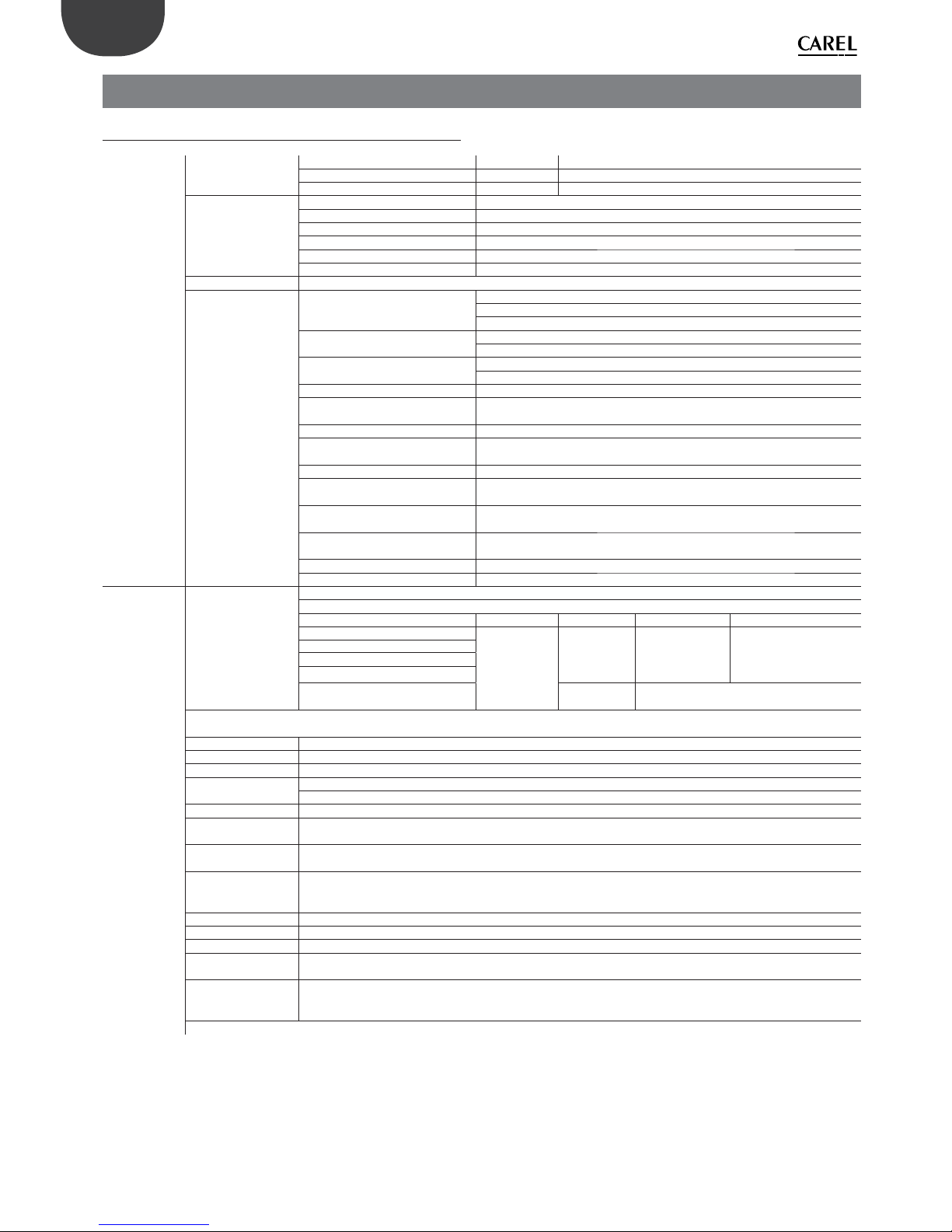
46
ENG
pCO5plus +0300020EN rel. 1.2 - 07.11.2013
8. TECHNICAL SPECIFICATIONS
8.1 pCO5+ Technical Specifi cations
Physical specifi -
cations
Dimensions
SMALL 13 DIN modules 110 X 227,5 X 60 mm
MEDIUM, LARGE, EXTRALARGE 18 DIN modules 110 X 315 X 60 mm
BUILT-IN DRIVER 18 DIN modules 110 X 315 X 75 mm
Plastic case
Mounting Can be mounted on DIN rail in accordance with DIN 43880 and IEC EN 50022
Material Technopolymer
Flame retardancy V2 (standard UL94) and 850 °C (standard IEC 60695)
Temperature for the ball pressure test 125 °C
Creeping current resistance ≥ 250 V
Colour White RAL 9016
Built-in terminal PGD1 (132x64 pixel) with backlit keypad
Other characteristics
Operating conditions
P+(3, 5)*******0** (no built-in terminal): -40T70 °C, 90% RH non-condensing(*)
P+(3, 5)*******E** (with built-in terminal): -20T60 °C, 90% RH non-condensing
(*) with Ultracap module installed: -40T60°C
Storage conditions
P+(3, 5)*******0** (no built-in terminal): -40T70 °C, 90% RH non-condensing
P+(3, 5)*******E**(with built-in terminal): -30T70 °C, 90% RH non-condensing
Protection rating
Models with USB port and/or Ultracap module: IP20 (front panel only)
Models without USB port and without Ultracap module: IP40 (front panel only)
Control pollution situation 2
Class of protection against electric
shocks
to be integrated into Class I and/or II units (on versions without valve driver), and
Class I units (on versions with valve driver)
PTI of insulating materials PCB: PTI 250 V; insulating material: PTI 175
Period of electrical stress across
insulating parts
long
Type of action 1C; 1Y in SSR versions
Type of disconnection or
microswitching
microswitching
Category of resistance to heat and
fi r e
Category D (UL94-V2)
Ageing characteristics (operating
hours)
80.000
No. of automatic operating cycles 100.000 (EN 60730-1); 30.000 (UL60730)
Rated impulse voltage 2500V
Electrical speci-
fi cations
Power supply
SMALL, MEDIUM, LARGE, EXTRALARGE: Use a dedicated, class 2, 50 VA safety isolating transformer
BUILT IN DRIVER: Use a dedicated, class II, 100 VA safety isolating transformer
Vac P (Vac) Vdc P ( Vdc)
SMALL
24 Vac (+10/-
15%), 50/60 Hz
to be protected
by 2.5 A T
external fuse
45 VA
28 to 36 Vdc
(-20/+10%) to be
protected by 2.5 A
T external fuse
30 W
MEDIUM
LARGE
EXTRALARGE
BUILT-IN DRIVER
(BUILT-IN VALVE DRIVER)
90 VA Not allowed
Attention: the pCO5+ with built-in driver must be powered with alternating current and the secondary winding of the power supply transformer
(G0) must be earthed.
Terminal block With plug-in male/female connectors
Cable section min 0.5 mm
2
- max 2.5 mm
2
CPU 32 bit, 100 MHz
Non-volatile memory
(FLASH)
P+3**********: 5 MB (2 MB BIOS + 3 MB application program + 2MB memory log fi le)
P+5**********: 9 MB (2 MB BIOS + 7 MB application program + 4MB memory log fi le)
Data memory (RAM) 3.2 MB (1.76 MB BIOS + 1.44 MB application program)
Buff er memory T
(EEPROM)
13 kB
Parameter memory P
(EEPROM)
32 kB (not visible from pLAN)
Working cycle duration
(medium complexity
applications)
0.2 s (typical)
Clock with battery Supplied, accuracy 100 ppm
Buzzer Can be software-enabled only via built-in terminal
Battery 3 Vdc lithium button battery (24x3 mm), code CR2430
Software class and
structure
Class A
Voltage surge
immunity category
(IEC EN 61000-4-5)
Category III
The device is not designed to be hand-held when powered
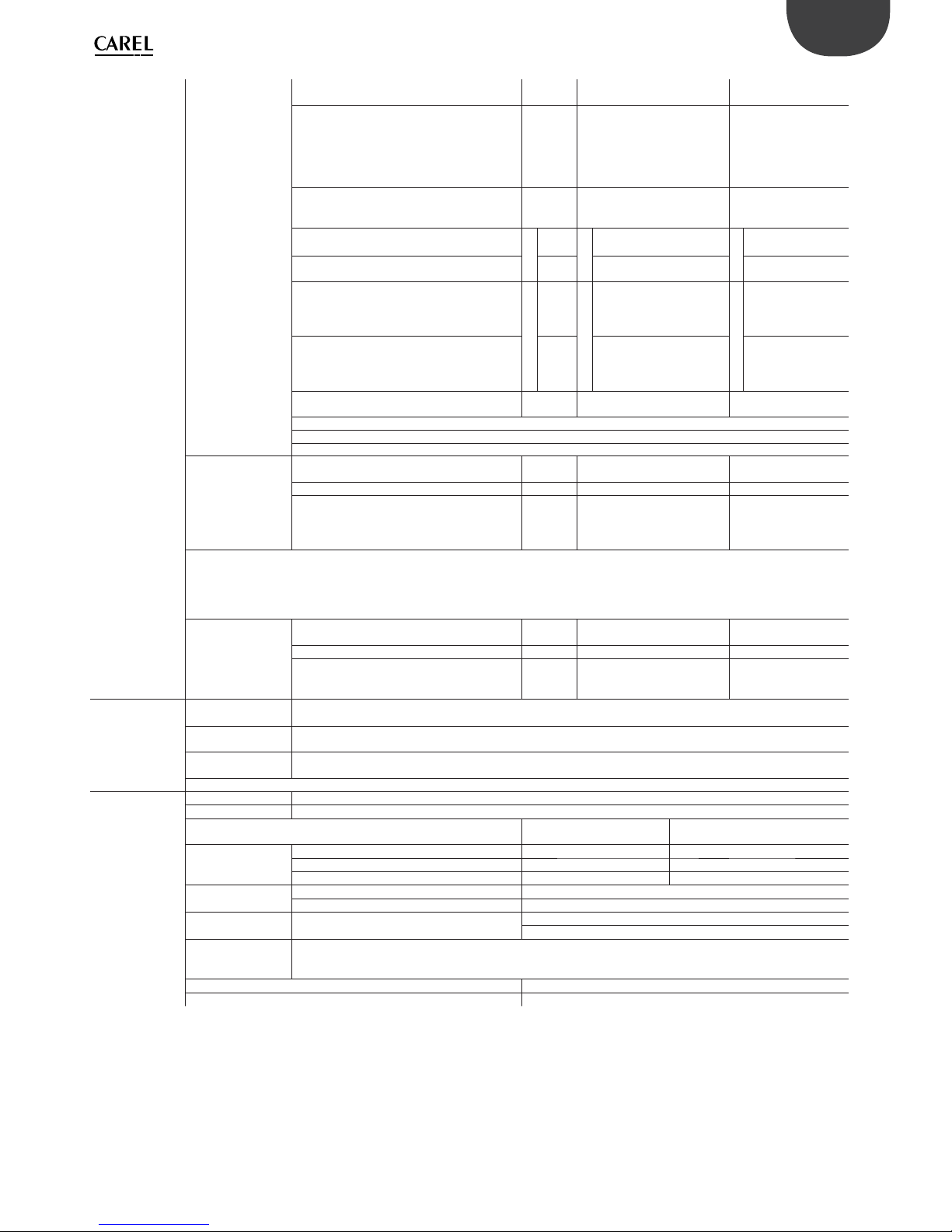
47
ENG
pCO5plus +0300020EN rel. 1.2 - 07.11.2013
Universal inputs/
outputs
U...
Analogue inputs,
Lmax = 30 m (max.
no.)
SMALL
MEDIUM/ BUILT-IN DRIVER/
EXTRALARGE
LARGE
- CAREL NTC probes (-50T90°C; R/T 10 kΩ±1%
at 25°C)
- NTC HT (0T150°C)
- PTC (600Ω to 2200Ω)
- PT500 (
-100T300°C)
- PT1000 (-100T400°C)
58 10
- PT100 probes (-100T400°C) 2
3 (2 on U1 to U5,
1 on U6 to U8)
4 (2 on U1 to U5,
1 on U6 to U8, 1 on U9
to U10)
- 0 to 1 Vdc/0 to 10 Vdc signals from controllerpowered probes (*)
Tot. max. 5
5
Tot. max.
8
6
Tot. max. 10
6
- 0 to 1 Vdc/0 to 10 Vdc signals from externally
powered probes (*)
58 10
- 0 to 20 mA/4 to 20 mA inputs from controllerpowered probes (*)
Tot. max.
4
4
Tot. max.
7
6 :
(max. 4 on U1 to U5,
3 on U6 to U8)
Tot. max.
9
6
(max. 4 on U1 to U5,
3 on U6 to U8,
2 on U9 to U10)
- 0 to 20 mA/4 to 20 mA inputs from externally
powered probes (*)
4
7 :
(max. 4 on U1 to U5,
3 on U6 to U8)
9 :
(max. 4 on U1 to U5,
3 on U6 to U8,
2 on U9 to U10)
- 0 to 5 V signals from controller-powered
ratiometric probes (*)
56 6
Input accuracy: ±0.3% fs
Time constant for each input: 0.5 s
Classifi cation of measuring circuits (IEC EN 61010-1): Category I
Non-optically-isolated
digital inputs, Lmax =
30 m (max. no.)
SMALL
MEDIUM/ BUILT-IN DRIVER/
EXTRALARGE
LARGE
- Voltage-free contacts 5 8 10
- Fast digital inputs
Type: voltage-free contact
Max. current: 10 mA
Max. frequency 2 kHz and resolution ±1 Hz
max 2
4
(max. 2 on U1 to U5,
max. 2 on U6 to U8)
6
(max. 2 on U1 to U5,
max. 2 on U6 to U8,
2 on U9 to U10)
Attention:
• To avoid irreparably damaging the controller, externally powered active probes (0 to 1 V, 0 to 10 V, 0 to 20 mA, 4 to 20 mA) should be provided
with adequate current protection and the current should be <100 mA.
• Ratiometric probes can be powered by the controller only.
• at power on, universal inputs/outputs are short circuited to GND for about 500ms up to the end of the confi guration.
Non-optically-isolated
analogue outputs
(max. no.), Lmax =
30 m
SMALL
MEDIUM/ BUILT-IN DRIVER/
EXTRALARGE
LARGE
0 to 10 Vdc (*) (max. current 2 mA) 5 8 10
PWM (0/3.3 Vdc output, max. current 2 mA,
frequency: 2 kHz asynchronous, 100 Hz
asynchronous)
58 10
Power supply
for probes and
terminals
+Vdc
Active probes can be powered by the 24/21 Vdc ±10% (*) (P+5*/P+3*) available on terminal +VDC (J2). The max.
available current is 150 mA, protected against short-circuits.
+5Vref
To power the 0 to 5 V ratiometric probes use the 5 Vdc (*) (±5%) available on terminal +5VREF(J24). The max. available
current is 60mA.
Vterm
P+3**********: 21 Vdc ± 10% (*); P+5**********: 24 Vdc ± 10% (*)
To be used to power an external terminal in alternative to the one connected to J10, Pmax = 1.5 W
Attention: For lengths greater than 10 m use a shielded cable with earthed shield. In any case the max. allowable length is 30 m.
Digital inputs
ID...
IDH...
Type Optically-isolated
Lmax 30 m
no. opto-isolated inp.
24 Vac or 24 Vdc
no. opto-isolated inp. @ 24 Vac/Vdc or
230 Vac - 50/60 Hz
Maximum number
SMALL 8 None
MEDIUM/ BUILT-IN DRIVER/EXTRALARGE 12 2
LARGE 14 4
Min. pulse detection
time on digital inputs
Normally open (open-closed-open) 200 ms
Normally closed (closed-open-closed) 400 ms
Power supply to
inputs
External
IDH...: 230 Vac (+10/-15%) 50/60 Hz
ID...: 24 Vac (+10/-15%) 50/60 Hz o 28...36 Vdc (+10/-20%)
Classifi cation of
measuring circuits
(IEC EN 61010-1)
Category I: 24 Vac/Vdc (J5, J7, J20)
Category III: 230 Vac (J8, J19)
Current draw on 24 Vac/Vdc digital inputs 5 mA
Current draw on 230 Vac digital inputs 5 mA
Notes:
• to avoid electromagnetic interference, separate as much as possible the probe and digital input cables from the cables carrying inductive loads and the power
cables. Never run power cables and probe signal cables in the same conduits (including the ones in the electrical panels);
• the two 230 Vac or 24 Vac/Vdc inputs on terminals J8 (ID13, ID14) or J19 (ID15, ID16) have the same common pole and must therefore be powered at the same
voltage (230 Vac or 24 Vac/Vdc). The two inputs are provided with operational insulation; reinforced insulation is provided between the inputs and the rest of the
controller;
• ID1 to ID8, ID9 to ID12, ID17, ID18 are functionally isolated from the rest of the controller;
• for DC digital inputs (24 Vdc), either the + or the - can be connected to the common terminal;
• the rating of the external contact connected to the digital inputs must be at least 5 mA;.

48
ENG
pCO5plus +0300020EN rel. 1.2 - 07.11.2013
Analogue outputs
Y...
Type 0 to 10 V optically-isolated on Y1 to Y6
Lmax 30 m
Maximum number
SMALL, MEDIUM/ BUILT-IN DRIVER/EXTRALARGE 4 Y1...Y4 a 0...10 V
LARGE 6 Y1...Y6 a 0...10 V
Power supply External 24 Vac (+10/-15%) or 28 to 36 Vdc on VG(+), VG0(-) (*)
Accuracy Y1...Y6 ±2% full scale
Resolution 8 bit
Settling time Y1...Y6 from 1 s (slew rate 10 V/s) to 20 s (slew rate 0.5 V/s) selectable via SW
Maximum load 1 kΩ (10 mA)
Warnings:
• for lengths greater than 10 m use a shielded cable with earthed shield;
• a 0 to 10 Vdc analogue output can be connected in parallel to other outputs of the same kind, or alternatively to an external source of voltage. The higher voltage
will be considered. Correct operation is not guaranteed if actuators with voltage inputs are connected;
• power the VG-VG0 analogue outputs at the same voltage on G-G0: connect G to VG and G0 to VG0. This applies in case of both alternating or direct current power
supplies.
Digital
outputs
NO..., NC...
Type Relay. Min. contact current: 50 mA
Maximum
number
8: SMALL; 13: MEDIUM/ BUILT-IN DRIVER; 18: LARGE; 29: EXTRALARGE
Insulation
distance
The relay outputs have diff erent features depending on the controller model. The outputs can be divided into groups. Relays belonging
to the same group (individual cell in the table) have operational insulation and must therefore be powered at the same voltage.
Between groups (between cells in the table) there is reinforced insulation, so the relays can be powered at diff erent voltages. There is
also reinforced insulation between each terminal of the digital outputs and the rest of the controller.
Relays with same insulation
Group
Composition
of groups
Model 1 2 3 4 5 6 7 8 9 10 11
SMALL 1...3 4...6 7 8 - - - - --Type of relay Type A Type A Type A Type A - - - ---MEDIUM/BUILTIN DRIVER
1...3 4...6 7 8 9...11 12 13 ----
Type of relay Type A Type A Type A Type A Type A Type A Type A - --LARGE NO 1...3 4...6 7 8 9...11 12 13 14...15 16...18 -Type of relay Type A Type A Type A Type A Type A Type A Type A Type A Type A -EXTRALARGE 1...3 4...6 7 8 9...11 12 13 14...16 17...20 21...24 25...29
Type of relay Type A Type A Type A Type A Type A Type A Type A Type B Type B Type B Type B
Number of
change-over
contacts
1: SMALL (relè 8)
3: MEDIUM e EXTRALARGE (relays 8, 12, 13)
5: LARGE NO (relays 8, 12, 13, 14 e 15)
Note: The output relays have diff erent features depending on the model of pCO5+.
Switchable
power
Type A relay
Nameplate
information
SPDT, 2000 VA, 250 Vac, 8A resistive
Certifi cation
UL60730 2A resistive, 250Vac, 30.000 cycles Pilot duty C300, 240Vac, 30.000 cycles
EN 60730-1 2(2)A, 250Vac, 100.000 cicli
Type B relay
Relay nameplate
information
SPST, 1250 VA, 250 Vac, 5A resistive
Certifi cation
UL60730 1A resistive, 250Vac, 30.000 cycles Pilot duty C300, 240Vac, 30.000 cycles
EN 60730-1 1(1), 250Vac, 100.000 cicli
SSR outputs
(on models
where
provided)
Maximum number
1: SMALL (output 7); 2: MEDIUM and EXTRALARGE (outputs 7 and 12); 3 or 4: LARGE (outputs 7, 12, 14 or 7, 12, 14, 15)
Working voltage 24 Vac/Vdc SELV 230Vac
Load current (MAX) 1 A 70mA
Pulse load current (MAX)
1,2 A 150mA
Warnings:
• if the load requires a higher current, use an external SSR;
• to power external loads, use the same power supply as the pCO (connected to terminals G-G0); this must always be dedicated and not in common with the
power supply to other devices (e.g. contactors, coils, etc.);
• to simplify wiring, the groups of digital outputs have two common pole terminals;
• make sure that the current running through the common terminals does not exceed the rated current of each terminal, i.e. 8A.
(*) class 2

49
ENG
pCO5plus +0300020EN rel. 1.2 - 07.11.2013
Serial ports
for +/- use AWG 20-22 twisted pair shielded
cable
Serial Type/Connectors Characteristics
Serial 0 pLAN/J10, J11 • Built into main board
• HW driver: asynchronous half duplex RS485 pLAN
• Not optically isolated
• Connectors: 6-pin telephone jack + 3-pin plug-in connector p. 5.08
• Max. length: 500 m
• Max. data rate: 115200 bit/s
• Max. number of devices connectable: 32
Serial ONE BMS 1 Serial Card • Not built into main board
• HW driver: not present
• Can be used with all optional BMS cards of the pCO family
Serial TWO FieldBus 1 Serial
Card
• Not built into main board
• HW driver: not present
• Can be used with all optional Fieldbus cards of the pCO family
Serial THREE BMS 2 / J25 • Built into main board
• HW driver: asynchronous half duplex RS485 slave
• Optically-isolated/non-optically-isolated serial(*)
• 3-pin plug-in connector p. 5.08
• Max. length: 1000 m
• Max. data rate: 38400 bit/s
• Max. number of devices connectable: 16
Serial FOUR Fieldbus 2/J26
(and J23 on Large
and Extralarge
versions)
• Built into main board
• HW driver: asynchronous half duplex RS485 master/slave(**)
• J23: not optically isolated
• J26: optically isolated/not optically isolated
• 3-pin plug-in connector p. 5.08
• J23 and J26 are both managed by the same protocol as serial 4, with the
advantage of being electrically independent.
(*): both models are available;(**): confi gurable port J26: see par. 3.2.
Note: In industrial/residential applications with distances greater than 10 m, use
shielded cable with earthed shield.
In domestic applications (EN 55014), regardless of cable length, in versions without
valve driver, the connection cable between controller and terminal and the serial cable
must be shielded and earthed on both sides.
Model with driver for electronic expansion valve
Valve compatibility
CAREL: E*V****
ALCO: EX4; EX5; EX6; EX7; EX8 330 Hz (recommended by CAREL); EX8 500 Hz (as per ALCO specifi cations)
SPORLAN: SEI 0.5-11; SER 1.5-20; SEI 30; SEI 50; SEH 100; SEH175
Danfoss: ETS 12.5-25B; ETS 50B; ETS 100B; ETS 250; ETS 400
CAREL: Two CAREL EXVs as for EVD EVOLUTION TWIN
SPORLAN: SER(I) G, J, K
Motor connection
Shielded 4-wire cable CAREL code E2VCABS*00, or AWG22 shielded 4-wire cable Lmax =10 m, or AWG14 shielded 4-wire cable Lmax = 50
m
Digital input
connection
Digital input to be activated with voltage-free contact or transistor to GND.
Making current 5mA; max. length <10 m.
Probes
Max. length 10 m or up to 30 m with shielded cable
S1 Ratiometric pressure probe (0 to 5 V) Resolution 0,1 % fs Measurement error: 2% fs maximum; 1% typical
Resolution 0.1% fs Resolution 0,5 % fs Measurement error: 8% fs maximum; 7% typical
Measurement error: 2% fs maximum;
1% typical
Resolution 0,1 % fs Measurement error: 2% fs maximum; 1% typical
Electronic pressure probe (4 to 20 mA)
Resolution 0,5 % fs Measurement error: 8% fs maximum; 7% typical
S2 Low temperature NTC 10 kΩ a 25 °C, -50T90 °C errore di misura: 1°C nel range -50T50 °C; 3°C nel range +50T90 °C
High temperature NTC 50 kΩ a 25 °C,-40T150 °C Measurement error: 1.5 °C in the range -20T115°C, 4 °C in the range
outside of -20T115 °C
Combined NTC 10 kΩ a 25 °C,-40T120 °C Measurement error: 1°C in the range -40T50 °C; 3°C in the range
+50T90 °C
0 to 10 V input (max. 12 V) Resolution 0,1 % fs Measurement error: 9% fs maximum; 8% typical
S3 Ratiometric pressure probe (0 to 5 V) Resolution 0,1 % fs Measurement error: 2% fs maximum; 1% typical
Electronic pressure probe (4 to 20
mA)
Resolution 0,5 % fs Measurement error: 9% fs maximum; 8% typical
Combined ratiometric pressure probe
(0 to 5 V)
Resolution 0,1 % fs Measurement error: 2% fs maximum; 1% typical
4 to 20 mA input (max. 24 mA) Resolution 0,5 % fs Measurement error: 9% fs maximum; 8% typical
S4 Low temperature NTC 10 kΩ a 25 °C,-50T105 °C; Measurement error: 1 °C in the range -50T50 °C; 3°C in the range
50T90 °C
High temperature NTC 10 kΩ a 25 °C,-40T150 °C Measurement error: 1.5 °C in the range -20T115 °C; 4 °C in the range
outside of -20T115 °C
Combined NTC 10 kΩ a 25 °C, -40T120 °C Measurement error 1 °C in the range -40T50 °C; 3°C in the range
+50T90 °C
Power to active
probes (VREF)
Programmable output: +5 Vdc ±2% or 12 Vdc ±10%, Imax = 50 mA
Emergency power
supply
Optional Ultracapacitor module (PCOS0WUC20 or EVD0000UC0). If the controller works constantly at temperatures near the upper limit
of 60°C it is recommended to use the external module code EVD0000UC0, if possible placed in the coolest point of the panel. Modules
PCOS0WUC20 and EVD0000UC0 can be connected to the same controller at the same time, thereby doubling the energy available for
closing the valves. Important: The module only powers the valve driver and not the controller.

50
ENG
pCO5plus +0300020EN rel. 1.2 - 07.11.2013
8.2 Conformity to standards
Electrical safety EN 60730-1, EN 60730-2-9, EN 61010-1, UL60730
Electromagnetic
compatibility
Versions without valve driver: EN 61000-6-1, EN 61000-6-2, EN 61000-6-2/EC, EN 61000-6-2/IS1, EN 61000-6-3, EN 61000-6-4; EN 55014-1,
EN 55014-2, EN 55014-2/EC, EN 55014-2/A1, EN 55014-2/IS1, EN 55014-2/A2
Versions with valve driver, with or without Ultracap module: EN 61000-6-1, EN 61000-6-2, EN 61000-6-2/EC, EN 61000-6-2/IS1, EN610006-3, EN 61000-6-4
Tab. 8.a
8.3 Models
The following table shows the characteristics of the models, divided by
code number. For the purchase code numbers please refer to the price
list.
Code Description Classifi cation
P+5********** 9 MB+4MB memory log fi le
Memory
P+3**********
5 MB+2MB memory log fi le (
)
P+5*****0**** Relay digital outputs
Type of digital outputP+5*****1...6**** 1 to 6 SSR outputs at 24 V
P+5*****A...F**** 1 to 6 SSR outputs at 230 V
P+5****0***** Standard
Connectivity
P+5****A***** Non-optically-isolated BMS2/Non-optically-isolated Fieldbus2
P+5****B***** Optically-isolated BMS2/Non-optically-isolated Fieldbus2
P+5****C***** Optically-isolated BMS2/Optically-isolated Fieldbus2
P+5***0****** No USB port
USB port
P+5***A****** USB port
P+5******0*** Without valve driver
Valve
driver
P+5******1*** 1 CAREL valve driver
P+5******2*** 2 CAREL valve drivers
P+5*******0** Without terminal Built-in
terminal
P+5*******E** Con PGD1 terminal
P+5********S* Small
Size
P+5********M* Medium
P+5********L* Large
P+5********Z* Extralarge
P+5*********0/1 Single/multiple Packaging
Tab. 8.b
On models P+3**B00*0(0,E)(S,M,L,Z)0
8.4 Connectors
Code Description Classifi cation
P+**CON*** CAREL standard
Type
P+**C***** Customer personalization
P+*****0** Screw-on
Type of terminal
P+*****1** With spring
P+*****2** Insulated
P+*****3** Crimp-on
P+******X0 Compact
Size
P+******S0 Small
P+******M0 Medium
P+******L0 Large
P+******Z0 Extralarge NO
P+******10 Medium 1 driver
P+******20 Medium 2 drivers
Tab. 8.c
Electrical specifi cations of plug-in connectors used
Type of connector
Pitch 5,08
Cable size 0,25 mm
2
- 2,5 mm2 (AWG: 24 a 12)
Stripping length 7 mm
Screw thread M3
Tightening torque 0,5...0,6 Nm
Tab. 8.d
Cable AWG and size cross-reference
AWG
Size (mm2) MAX. current
20 0,5 2
15 1,5 6
14 2,5 8
Tab. 8.e

51
ENG
pCO5plus +0300020EN rel. 1.2 - 07.11.2013
9. APPENDIX
9.1 Smart Key: operating instructions
start
mode
start
mode
Fig. 9.a
Programming the Smart Key via Personal Computer
The operating modes described in the table below can be confi gured
using a program on the PC. The program can also load the software to the
key or transfer logged data from the controller to disk.
Type Function Mode button
B
Update software from key to pCO
(BIOS, application, parameters, etc.)
Disabled
C*
Copy software from pCO to pCO
(BIOS, application, parameters, etc.)
Switches the key from write
mode to read mode
D Read logs Disabled
E
Read logged data and software from
pCO (BIOS, application, parameters,
etc.)
Disabled
F Read logged data Disabled
G Copy from pCO to pCO and read logs
Switches the key to write
mode, read mode and read
logs mode
*: Default mode
The key is factory-programmed in read/write mode (type C) so that it can
be used immediately to transfer software from one controller to another.
When the key is connected to the personal computer, the symbols have
the following meanings:
Flashing Waiting for connection to PC
Alternating When connected to PC indicates data transfer in
progress
The programming key is compatible starting from BIOS version 3.43 and
BOOT version 3.01. For more detailed information on programming the
key, see the pCO Manager program manual.
Using the Smart Key with the pCO
Switch off the pCO, remove any peripherals connected in the pLAN
and plug the key into the telephone connector on the controller. When
switching on again, all the symbols light up momentarily and the buzzer
emits a beep. A few seconds later the key becomes operational. During
this period the symbols
will fl ash. The controller then enters
programming mode and the start button lights up steadily. Press the
button to start data transfer.
Important: If the key is type B, C or G (in write mode) pressing the
start button will immediately delete the software already loaded on the
pCO.
Important: Do not remove the key while data is being transferred
to the key itself, as the fi le being transferred will be lost and the
corresponding space will not be restored. To restore the original capacity
all the fi les will need to be deleted. If the key is type “C” or “G”, simply
perform a new application read operation.
Meanings of Buttons/Symbols
Flashing: The key is connecting to the pCO. During this phase,
which may last a few seconds, the start button is disabled.
start Flashing: The key has detected the pCO and is checking the
access rights.
start +
On steady: Pressing the start button will start writing the
software to the pCO.
start +
On steady: Pressing the start button will start reading the
software from the pCO.
start +
On steady: Pressing the start button will start reading the logs
from the pCO.
mode
On steady: In case of C or G keys, pressing the button for 1
second switches from read to write.
Tab. 9.a
If the key is type C of G, pressing the “mode” button for 1 second switches
from read to read logs (G only) or to write. The symbols
(write to pCO),
(read from pCO), (read logs) refl ect the selected status. If the key
is not type “C” or “G”, the “mode” button is disabled and off . The
“start” button starts the read or write operation, indicated by the fl ashing
of the corresponding symbol (
or ) at a frequency proportional to
the progress of the operation.
When the operation is completed, the buzzer will sound intermittently
for 2 seconds. Pressing the “start” button again will make the buzzer
sound without repeating the operation. To repeat the operation, the key
must fi rst be unplugged. In case of error the symbol will light up together
with the other LEDs. The following table can help you fi nd the cause of
the problem.
Errors before pressing the START button
+ +
Symbols fl ashing
Communication error: No response
from the pCO or: Key fi rmware version
is incompatible.
+mode
Symbols steady Password error
+mode
Symbols fl ashing Type of key is incompatible.
+
Symbols steady The key is missing one or more required
fi les (memor y empty; no kit for the type
of pCO connected).
+ +start
Symbols steady
+ fl ashing start
Incompatibility between the software on
the key and the pCO HW.
+
+mode
Symbols steady
+ fl ashing mode
Incompatibility between pCO
application and HW (application size).
+ +
Symbols steady No logged data present on the pCO.
Steady Type of key not programmed.
Tab. 9.a
Errors after pressing the START button
+start+ +buzzer
Symbols fl ashing
and buzzer sounding
intermittently
Write operation failed.
+start+ +buzzer
Symbols fl ashing
and buzzer sounding
intermittently
Read operation failed.
+start+
+buzzer
Symbols fl ashing
and buzzer sounding
intermittently
Read logs operation
failed.
+ +
Symbols steady +
fl ashing
Incompatibility between
log confi guration and
pCO HW (no dedicated
fl ash memory). This error
does not prevent writing
other fi les.
+
Steady
Insuffi cient space to read
logs.
Flashing Generic error
Tab. 9.b

52
ENG
pCO5plus +0300020EN rel. 1.2 - 07.11.2013
9.2 pCO Manager: operating instructions
pCO Manager is a program that lets you manage all the confi guration,
debugging and maintenance operations on CAREL pCO Sistema
devices. pCO Manager can be installed by itself or as part of the 1Tool
programming environment.
Installing pCO Manager
Go to http://ksa.carel.com and, in the section pCO Sistema, select pCO_
manager. After you accept the general conditions of the software’s free
use licence, a window will open from which you can download the fi le
pCO_manager.zip. Install the program on your computer.
Connecting the PC to the pCO controller
Connect a cable with USB/RS485 converter to the USB port on the
computer, and connect the converter to a telephone cable plugged into
the pLAN port of the pCO. Additional connection methods are described
in par. 6.5.
J10
FieldBus card BMS card
CVSTDUTLF0
POWER SUPPLY
Fig. 9.b
Upon launching, pCO Manager will display a screen showing the
connection settings in the upper right-hand corner. Choose:
1) “connessione locale” [local connection]
2) baud rate: Auto
3) “ricerca dispositivo” [fi nd device]: Auto (pLAN)
As for the port number, follow the Wizard’s instructions for the port to be
identifi ed automatically (e.g. COM4).
Fig. 9.c
Switch the controller off and then on again and use the Connect
command to establish the connection. When the connection is
established the fl ashing message “ONLINE” will appear at the bottom left
of the screen.
Fig. 9.d
Installing the application program
Select the directory containing the application program fi les and click
“Upload” to upload the program to the pCO controller.
Fig. 9.e
Commissioning
Using the mouse, select “Commissioning” at the bottom left. A new work
environment will appear.
Fig. 9.f
Click on “confi gura dispositivo” [confi gure device] to display all the
application variables. The variables can be selected according to the
categories that appear at the bottom.
Fig. 9.g
Changing a parameter
Select the parameter category and then the parameter that you want
to edit. The parameter (e.g. recovery.recovery_type) will be highlighted
in blue.
Fig. 9.h
1) Double-click on the column marked “letto” [read]. A window will appear
in which you can enter the new value for the parameter.
Fig. 9.i

53
ENG
pCO5plus +0300020EN rel. 1.2 - 07.11.2013
2) Enter the new value (e.g. 3) and click OK. The new value will appear in
the col
umn marked “scritto” [written]. To write the parameter to the pCO
controller, right-click and select “scrivi selezionate” [write selected]. The
new value will appear in the column marked “scritto” [written], meaning
that the parameter has been written to the controller.
Fig. 9.j
Click on “Salva” [Save] to generate the project’s “.2cw” fi le.
Commissioning: basic concepts
Note: The following paragraphs are from the online help of pCO
Manager, to which the user is referred for further details.
Commissioning is a confi guring and real-time monitoring software that
can be used to supervise the performance of an application program
installed on a pCO, to start up the pCO and to perform debugging and
maintenance.
With this software the user can set the confi guration parameters, edit the
values of volatile and permanent variables, save on fi le the trends of the
unit’s main quantities, manually manage the unit’s I/O using simulation fi les
and monitor/reset the alarms of the unit on which the device is installed.
Work carried out with Commissioning is preceded by confi guring the work
environment, which is typically done by the project designer. The active
project in 1Tool is automatically loaded by pCO Manager.
The project designer can use the confi guration functions of Commissioning
to decide which variables should be subjected to monitoring, logging,
trend-monitoring and event-monitoring, to organize variables into
categories and to create sets of confi guration parameters.
Operators using Commissioning for maintenance will be able to see the
necessary variables and to draw from preset confi guration values.
Support les
Once the design of the application is completed, 1Tool generates a
number of fi les in the compiling stage, two of which are required by
Commissioning:
• <nomeApplicativo>.2CF [<ApplicationName>.2CF] (variable descriptor)
• <nomeApplicativo>.2CD [<ApplicationName>.2CD] (category and
access profi le descriptor)
In addition to these fi les, the software also manages the <nome
applicativo>.DEV [<Application Name>.DEV] fi le, which contains the unit’s
preset parameters.
When the user has fi nished using Commissioning, whether for confi guration
or monitoring purposes, the following fi les can be generated:
• <nomeApplicativo>.2CW [<ApplicationName>.2CW] (descriptor for
categories, access profi les, monitoring groups)
• <nomefi leCommissioningLog>.CSV [<FilenameCommissioningLog>.
CSV] (fi le used for the commissioning log, containing data of the
variables logged during monitoring)
Therefore, to confi gure Commissioning the following fi les are required: .2CF,
2CD and, if necessary, the .DEV fi le, which can be imported or exported.
For monitoring purposes, in addition to the fi les above, it might also be
necessary to have the .2CW fi le, containing the defi nition of the work
environment. The commissioning log fi le is a simple output fi le.
pCO Load: basic concepts
pCOLoad is the module that manages:
• uploading to the fl ash memory (of the device or of the ProgKeyX key
installed on the pCO);
• uploading to the NAND memory of certain devices;
• downloading the log fi le, .DEV fi le and P memory (from the fl ash
memory);
• downloading fi les from the NAND memory, if present.
The fi les exchanged with the Flash memories of pCO controllers are:
• BOOT.BIN (download reserved, upload enabled from menu)
• BIOS.BIN (download reserved)
• <nomeApplicativo>.BLB [<ApplicationName>.BLB] (download
reserved)
• <nomeApplicativo>.BIN [<ApplicationName>.BIN] (download reserved)
• <nomeApplicativo>.DEV [<ApplicationName>.DEV]
• <nomeApplicativo>.GRT [<ApplicationName>.GRT] (upload only, from
which the .GRP fi le is extracted)
• <nomeApplicativo>.IUP [<ApplicationName>.IUP]
• <nomeApplicativo>.LCT [<ApplicationName>.LCT]
• <nomeApplicativo>.PVT [<ApplicationName>.PVT]
• <nomepCOlog>.BIN, <nomepCOlog>.CSV, <nomepCOlog_GRAPH>.
CSV [<pCOlogName>.BIN, <pCOlogName>.CSV, <pCOlog_
GRAPHName>.CSV] (only if log fi les have been confi gured, download
only).
The fi les exchanged with the NAND memories of pCO controllers are:
• any fi le that the pCO can independently copy to the fl ash memory (see
above list);
• external fi les (e.g. .pdf or .doc fi les for documentation).
LogEditor: basic concepts
LogEditor is the module used to confi gure the log fi les of pCO devices
(pCO logs). Confi guring pCO logs consists in defi ning a number of sets
of variables in which to specify which variables should be logged, the
logging method (by frequency or by event) and the minimum number
of loggings required. Confi guration is based on a binary fi le (.PVT – Public
Variable Table), which is generated by 1Tool and contains the descriptive
data of the variables that can be logged.
All the log confi gurations so defi ned are saved in the .LCT (Log
Confi guration Table) binary fi le, which must be uploaded to the pCO
together with the .PVT fi le. Log confi guration data is also saved in a fi le
that can be used only by LogEditor – the .LEF fi le, which must be saved to
be edited with LogEditor as necessary.
LogEditor can be used even when the device is not connected.
Once the fi les for logging are uploaded to the pCO, the pCO
saves the logged data in the following fi les:
• .BIN fi le containing all the data in binary format;
• .CSV fi le containing the same data in a generic format with values
separated by commas;
• *_GRAPH.CSV containing the same data to be used for charting purposes
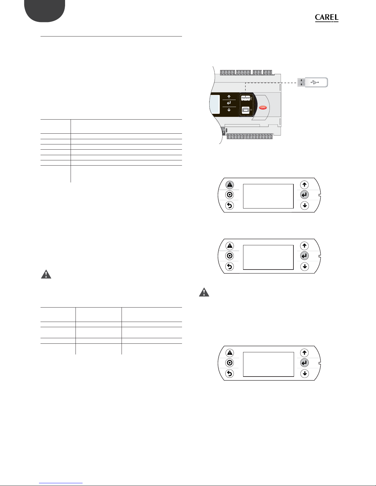
54
ENG
pCO5plus +0300020EN rel. 1.2 - 07.11.2013
9.3 Pendrive: operating instructions
File extensions, names and contents
Various types of fi les can be uploaded and downloaded and are
distinguished by their extension.
File names
In order to be recognised, the names of the directories and fi les on the
pendrive must have no more than 8 characters; the controller makes no
distinction between upper-case and lower-case characters. However,
during DOWNLOAD the names of the directories created by the controller
on the pendrive are always in upper-case.
FILE TYPES FOR UPLOAD
File
extension
Description
.IUP Contains the defi nitions of the screens on the terminal
.BLB Contains the application
.BIN Contains the application (with pLAN table)
.BLX Contains the logic of atoms custom in C language
.GRP Contains the graphics
.DEV Contains the preset confi guration parameter values
PVT, .LCT Contains the descriptions of the public variables to be
logged. Generated by 1Tool, this is used by the LogEditor
module and must be loaded together with the .LCT fi le
Downloaded fi les are saved in directories created automatically, with the
following name format:
NAMXY_WZ
Where:
NAM: identifi es the type of data downloaded (LOG for logs, BKP for the
application, DEV for the buff er memory, CPY for all the data from the
controller).
XY: progressive number from 0 to 99
WZ: controller pLAN address.
Example: A directory named LOG00_01 contains the log fi les (LOG)
downloaded from a device whose pLAN address is 1. Since the key
contained no directory of this type before download, it is indicated with
00.
Important: No more than 100 fi les of the same type can be
downloaded to the pendrive, as the directories created can only be
numbered with XY=00 to 99.
FILE TYPES FOR DOWNLOAD (controller pLAN address = 1)
File extension Directory name Description
.DWL LOG00_01 Logged data
.DWL,.DEV, .LCT,
.PVT
BKP00_01 Application
.DEV DEV00_01 Non-volatile parameters
.DWL, .DEV, .LCT,
.PVT
CPY00_01 All data on the controller
Tab. 9.c
The downloaded fi les to have fi xed names. In particular, the application
fi le is called “ppl–pCO.dwl”, the BIOS fi le “bios–pCO.bin”, the fi les
containing the logs and related information are “logs.dwl”, “logs.lot” and
“logs.pvt”, respectively. Finally, the buff er memory is saved to the fi le on
the pendrive.
Menu access
The following are the steps for accessing the pendrive management
menu. Procedure:
1. Connect the pendrive to the master port.
USB key
BMS card
Fig. 9.k
2. Press Alarm and Enter together for 3 seconds to enter the option
menu. Select FLASH/USB memory and press Enter to confi rm.
4:45&.*/'03."5*0/
-0(%"5"
05)&3*/'03."5*0/
'-"4)64#.&.03:
Fig. 9.l
3. Select USB pen drive and press Enter to confi rm.
/"/%'-"4)'*-&4
64#1&/%3*7&
Fig. 9.m
Important: Wait a few seconds after the pendrive has been
plugged in for it to be recognised by the controller. If the message “No
USB disk or PC connected” is displayed momentarily with the request to
connect a pendrive key or computer USB cable, wait a few seconds until
the recognition message is shown (“USB disk found”) and the following
screen appears.
4. Select UPLOAD.
4ELECTFUNCTION
61-0"%PENP$0
%08/-0"%P$0PEN
Fig. 9.n
Upload
An application plus BIOS or buff er memory (parameters) can be uploaded
from the pendrive. The following modes are available: automatic, autorun
and manual. Automatic and autorun modes require using confi guration
fi les.
Confi guration fi le structure
Confi guration fi les must start with the string “[FUNCTION]” followed by a
string that identifi es the function, as shown in the table.

55
ENG
pCO5plus +0300020EN rel. 1.2 - 07.11.2013
Function String
UPLOAD an application or a BIOS fi le
plus an application
Upload application
UPLOAD non-volatile memory (.dev) Upload non volatile memory
UPLOAD the entire contents of the pCO Copy pCO upload
After the description of the desired function, various options are available:
1. To copy the complete contents of the directory, simply write the
name of the directory (e.g. the entire contents of the CHILLER
directory):
[FUNCTION]
Upload non volatile memory
[DIR]
CHILLER
2. To copy just 1 fi le in a directory, enter the fi le’s name (e.g. the
CHILLER.DEV fi le in the CHILLER directory).
[FUNCTION]
Upload non volatile memory
[DIR]
CHILLER
CHILLER.DEV
To show a string on the display describing the operation being
performed, add the “[NAM]” instruction, followed by the string to display.
The following fi le will display the string:
“UPL CHILLER.DEV”
[FUNCTION]
Upload non volatile memory
[DIR]
CHILLER
[NAM]
UPL CHILLER.DEV
CHILLER.DEV
3. To select only some of the fi les in the same directory, list them after
a label. The following labels are allowed and must be entered in
the order shown in the table:
UPLOAD fi le labels
No. Label File type No. Label File type
1 [BIO] (*) fi le.bin 6 [PVT] fi le.pvt
2 [IUP] fi le.iup 7 [LCT ] fi le.lct
3 [BIN] fi le.bin, blb 8 [OED] fi le.oed
4 [DEV ] fi le.dev 9 [SGN] fi le.sgn
5 [GRP] fi le.grp
(*) BIO = BIOS fi le
Notes:
• to get the .bin file from the BIOS in the format available on http://ksa.
carel.com (.os file), unzip the .os file;
• the [IUP] label can be followed by one or more “.iup” files.
Important:
• the order in which the fi le names are entered is fundamental and must
not be changed;
• do not enter empty lines or spaces in the fi le (e.g. at the end of a line);
• each fi le after the last line of code must contain a “carriage return”
character (CR ), as shown in the following example.
•
Example: The following fi le will upload the BIOS and an application.
[FUNCTION]
Upload application
[DIR]
NEW AHU
[NAM]
BIOS+APPL+LOGSv58B36
bisn509.bin
[IUP]
AHU_EN.iup
AHU_IT.iup
[BIN]
AHU.blb
[DEV]
AHU.dev
[GRP]
AHU.grp
[PVT ]
AHU.pvt
[LCT]
AHU.lct
Automatic upload
To automatically upload the parameter memory using the fi rst
confi guration fi le shown in the preceding paragraph, access the system
menu as previously described and proceed as follows:
1. Select automatic mode. A screen is shown describing the function
of the buttons. Press Enter to confi rm.
4ELECTUPLOADMODE
"650."5*$.0%&
."/6"-.0%&
Fig. 9.o

56
ENG
pCO5plus +0300020EN rel. 1.2 - 07.11.2013
2. Confi rm by selecting Prg. A screen is displayed requesting
confi rmation to upload the non-volatile memory. Press Enter to
confi rm.
61-'*-&?%&7
Fig. 9.p
3. At the end a message will ask the user to remove the pendrive.
61-0"%*/('*-&
1-&"4&8"*5
Fig. 9.q
Upload in autorun mode
Uploading in autorun mode is a special case of uploading in automatic
mode. Unlike automatic mode, the user must wait for a specifi c message
to appear on the display to start or disable the operation described in the
confi guration fi le. To upload a fi le in autorun mode, a confi guration fi le
must be created and named “autorun.txt”.
Example of uploading BIOS+application. The upload involves two steps:
fi rst the BIOS is updated and then the application.
The information is shown on the pCO’s built-in display and on the pGD1
terminal, when both are featured.
Procedure:
1. Connect the pendrive to port A.
USB key
BMS card
Fig. 9.r
2. After a few seconds, Autorun mode starts. Press Enter to confi rm.
"65036/.0%&
61-0"%"11-*"5*0/
1RESS&/5&3TOSTART
&4$TOEXITAUTORUN
Fig. 9.s
3. The validity of the FW is checked and the BIOS is loaded.
'8VALIDATION
1LEASEWAIT
Fig. 9.t
4. The display fl ashes to indicate that after loading the new BIOS the
controller is being reset.
'8VALIDATION
1LEASEWAIT
Fig. 9.u
/0-*/,
pGD
Fig. 9.v
5. The test phase starts.
"PPLICATIONPROGRAM
CORRUPTEDORNOT
PRESENT
8"*5*/(FORUPGRADE
Fig. 9.w
/0-*/,
pGD
Fig. 9.x
6. The controller warns that no application has been loaded.
"PPLICATIONPROGRAM
CORRUPTEDORNOT
PRESENT
8"*5*/(FORUPGRADE
Fig. 9.y
/0-*/,
pGD
Fig. 9.z
7. The application update then starts.
6PLOADAPPL
1LEASEWAIT
Fig. 9.aa

57
ENG
pCO5plus +0300020EN rel. 1.2 - 07.11.2013
/0-*/,
pGD
Fig. 9.ab
8. Remove the pendrive. The update is complete. Wait for the display
to stop fl ashing, indicating that the controller is being reset before
restarting.
6PLOADCOMPLETE
3EMOVE64#KEY
ANDWAITRESET
Fig. 9.ac
/0-*/,
pGD
Fig. 9.ad
Important: As can be seen, when updating the BIOS and the
application, the pGD1 terminal shows the message “NO LINK”, meaning
that no connection is established. Do not remove the terminal and wait
for the end of the update procedure, when the pGD1 terminal replicates
the messages on the built-in display.
Note: Autorun run is especially useful in those cases in which the
same operation needs to be performed on several controllers. For
example, to load diff erent applications on controllers connected in a
pLAN network, only one autorun fi le needs to be created; this uploads
the various directories contained on the pendrive based on the address
of the controllers. The controller with address XY will only load the
directory called “nomedir_XY” [“DirName_XY”]. The pendrive then only
needs to be plugged into each controller to run the upload, confi rming
from the shared terminal.
Manual upload
To manually upload the contents of the pendrive the user must access
the management menu from the system screens, selecting UPLOAD and
then MANUAL. The fi les are selected by pressing ENTER when the cursor
is on the desired fi le name. A selected fi le is marked by the symbol “*”
on the left. Once the fi les have been selected (all in the same directory),
press PRG to start the upload. To display the contents of a directory press
ENTER. To go up one directory level press ESC. Once the upload has
started, the messages shown on the screen are the same as in automatic
and autorun mode.
Download
As mentioned above, the DOWNLOAD operation can be managed in two
ways:
1. Manual mode: follow the steps described in the paragraph
“Automatic upload” and select manual operation. Then each fi le
must be selected and downloaded.
2. Autorun mode: prepare a fi le called “autorun.txt”, containing a string
that identifi es the function to be performed.
Function String
DOWNLOAD logged data Download logs
DOWNLOAD the application Download application
DOWNLOAD non-volatile
memory
Download non volatile memory (.dev)
DOWNLOAD the entire
contents of the pCO
Copy pCO download
The result is the creation of fi les with the required extensions, which will
be placed in the respective directories as described in the paragraph “File
names”. When the operation is completed, the display shows a message
with the name of the directory created.
[FUNCTION]
Download application
The following screen will be displayed.
1. Press Enter to confi rm.
'8VALIDATION
1LEASEWAIT
Fig. 9.ae
2. Download completed.
0PERATIONCOMPLETE
%ATADOWNLOADED
TO#,1?
Fig. 9.af
Example: On the controller with address 1, the autorun fi le will create a
directory called BKP00_01 and copy the fi les APPL_PCO.DWL and FILE_
DEV.DEV to this directory.
Setting the password
If the application contains a password that must entered in a special
screen, this is requested for each DOWNLOAD/UPLOAD between the
pCO and the pendrive. The password is used to:
• protect the contents of the pCO from being downloaded to the
pendrive;
• protect the PC connection (this is a standard procedure in pCO Manager).
Connecting to a computer
Connect the slave USB port on the controller to the USB port on the
computer where pCO Manager is installed.
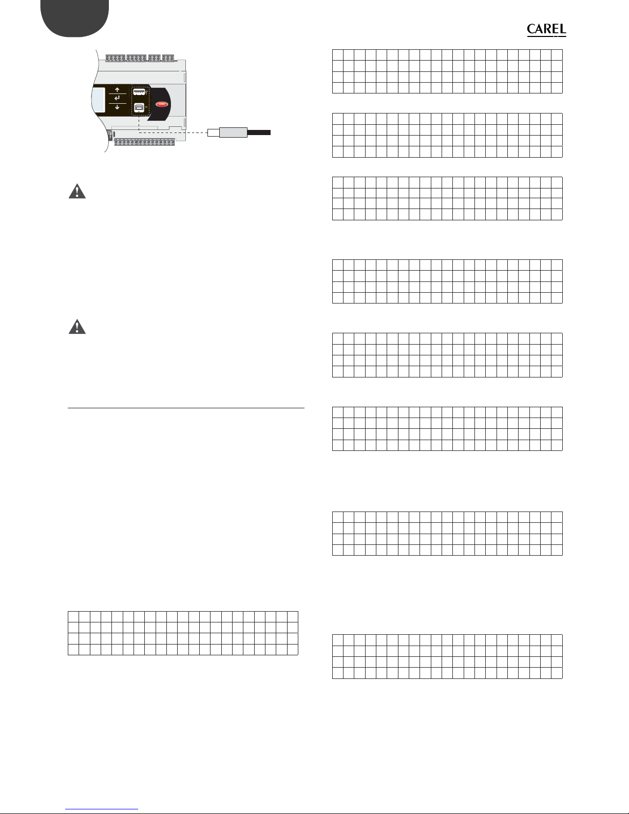
58
ENG
pCO5plus +0300020EN rel. 1.2 - 07.11.2013
USB connector
from computer
BMS card
Fig. 9.ag
Important:
• do not install any type of converter between the computer and port B,
even if requested by the program’s guided procedure;
• pCO Manager manages compressed fi les (.GRT/.OS).
Once the connection is established, the following operations are available:
1. UPLOADING the application or BIOS+application.
2. DOWNLOADING the non-volatile memory.
3. DOWNLOADING logged data.
4. Commissioning
5. Managing the NAND fl ash memory.
Once the USB cable is removed, the port will become available again
after approximately 5 s.
Important: If no connection is established with pCO Manager
after plugging in the USB cable, wait at least 1 minute before using the
USB ports again after removing the cable.
9.4 Confi guring pCOWeb/pCOnet from a
system screen
See par. 6.6 for information on how to access the BIOS system menu.
Starting from:
• BIOS release 5.16 BIOS, and from
• pCOWeb fi rmware version A1.5.0, and from
• pCOnet fi rmware version A485_A1.2.1
pCOWeb and pCOnet communication parameters can be confi gured.
The purpose is to confi gure the network (Ethernet for pCOWeb, RS485
for pCOnet) when the respective card is installed for the fi rst time. The
remaining parameters (alarms, events, etc.) can be confi gured using the
usual tools, i.e. BACset or web interface (pCOWeb only). Confi guration
can be done either when using the Modbus protocol or the CAREL
protocol, but only on the BMS1 serial port. The screens for confi guring
pCOWeb and pCOnet can be opened by accessing the system screens
and selecting OTHER INFORMATION and then PCOWEB/NET CONFIG.
Then, select “PCOWEB settings” to confi gure pCOWeb parameters or
“PCONET settings” to confi gure pCOnet parameters.
Confi guring pCOWeb
When you select “PCOWEB settings” the following screen will appear:
DHCP : - - -
I P ADDRESS
---.---.---.---
After a short time the fi elds are populated with the current parameters.
If the fi elds are not populated with the current parameters, check the
fi rmware version of pCOWeb and the protocol used by the BMS serial
port. The parameters can now be edited by selecting the respective
fi elds using the ENTER button and setting the desired values using the
UP/DOWN buttons. If the DHCP option is set to ON, the IP address and
Netmask fi elds cannot be changed. Pressing ENTER repeatedly will display
all the parameters available, as listed in the following screens:
Ne tmas k :
---.---.---.---
Gat eway :
---.---.---.---
DNS1 :
---.---.---.---
DNS1 :
---.---.---.---
BACnet ID:
-------
BACne t Type :
-------
Once the parameters have been chosen they can be updated by going to
the following screen and pressing ENTER.
PCOWEB CONFI G ENABLE
Upda t e pCOWeb? NO
While the parameters are being updated, the following message is
displayed:
PCOWEB CONFI G ENABLE
Please wai t for
end o f update
At the end, the screen shows:
PCOWEB CONFI G ENABLE
Upda t e comp l e t e
Reboo t pCOWeb t o
apply new setting
Confi guring pCOnet
When you select “PCONET settings” the following screen will appear:
BACnet ID:
-------
BACnet baud:
--------
After a short time the fi elds are populated with the current parameters.
The parameters can now be edited by selecting the respective fi elds
using the ENTER button and setting the desired values using the UP/
DOWN buttons. Pressing ENTER repeatedly will display all the parameters
available, as listed in the following screen:
BACne t MAC: - - Max Ma s t e r s : - - Max F r ame s : - - - - -
Once the parameters have been chosen they can be updated following
the procedure described for confi guring pCOWeb.


CAREL INDUSTRIES - Headquarters
Via dell’Industria, 11 - 35020 Brugine - Padova (Italy)
Tel. (+39) 049.9716611 - Fax (+39) 049.9716600
e-mail: carel@carel.com - www.carel.com
Agenzia / Agency:
pCO5plus +0300020EN rel. 11.2 - 07.11.2013
 Loading...