


Application program for pCO¹ and pCO
2
Standard air-conditioning units
Manual version 1.2 – April 11, 2003
Program code: FLSTDMCZ0E


To save time and money!
The thorough reading of this manual will ensure proper installation and safe use of the described device.
IMPORTANT WARNINGS
BEFORE INSTALLING OR HANDLING THE APPLIANCE, PLEASE CAREFULLY READ AND
FOLLOW THE INSTRUCTIONS CONTAINED IN THIS MANUAL.
The appliance this software is intended for has been expressly designed to ensure safe operation,
provided that:
• software is installed, programmed, used and maintained by qualified personnel in full observance of the
instructions contained in this manual;
• all conditions specified and contained in the appliance installation and use manual are met.
Any other use and modification to the appliance not expressly authorised by the manufacturer shall
be considered as improper.
Liability for injuries or damage caused by improper use lies exclusively with the user.


CONTENTS
1.0 GENERAL INFORMATION........................................................................................................................................................................ 3
1.1 THE PROGRAM .....................................................................................................................................................................................3
1.2 THE USER TERMINAL ......................................................................................................................................................................... 3
1.3 pCO1 MAIN BOARD.............................................................................................................................................................................. 5
1.4 pCO2 MAIN BOARD.............................................................................................................................................................................. 6
1.5 ELECTRONIC EXPANSION VALVE................................................................................................................................................... 7
1.6 ACCESSORIES....................................................................................................................................................................................... 8
2.0 BUILT-IN HUMIDIFIER .............................................................................................................................................................................9
2.1 SETTING THE PARAMETERS TO SELECT THE HUMIDIFIER....................................................................................................... 9
2.3 HUMIDITY AND STEAM PRODUCTION CONTROL...................................................................................................................... 10
3.0 BOARD CONNECTION MANAGEMENT (pLAN)................................................................................................................................. 11
3.1 pLAN PHYSICAL CONNECTIONS .................................................................................................................................................... 11
3.2 SETTING THE pLAN ADDRESS ........................................................................................................................................................ 11
3.3 HOW TO ASSIGN THE ADDRESSES ................................................................................................................................................ 11
3.4 pLAN STATUS......................................................................................................................................................................................12
3.5 CHECK pLAN ADDRESS.................................................................................................................................................................... 12
4.0 FIRST INSTALLATION AND SOFTWARE UPDATING ....................................................................................................................... 13
4.1 PROGRAM DOWNLOAD FROM HARDWARE KEY....................................................................................................................... 13
4.2 PROGRAM DOWNLOAD FROM COMPUTER................................................................................................................................. 13
4.3 INSTALLING THE DEFAULT PARAMETERS................................................................................................................................. 13
4.4 LANGUAGE SELECTION................................................................................................................................................................... 13
5.0 CONFIGURATION LIST...........................................................................................................................................................................14
5.1 DIGITAL INPUTS................................................................................................................................................................................. 14
5.2 ANALOGUE INPUTS...........................................................................................................................................................................14
5.4 DIGITAL OUTPUTS............................................................................................................................................................................. 14
5.3 ANALOGUE OUTPUTS.......................................................................................................................................................................15
5.5 CLOSE CONTR. UNIT WITH COILS CLOSE CONTR. UNIT WITH DIRECT EXPAN S. COIL .................................................. 15
6.0 LIST OF PARAMETERS AND DEFAULT VALUES .............................................................................................................................. 16
7.0 ALARMS .................................................................................................................................................................................................... 21
7.1 ALARM RELAYS.................................................................................................................................................................................21
7.2 TABLE OF ALARMS........................................................................................................................................................................... 22
8.0 SCREENS.................................................................................................................................................................................................... 23
8.1 LIST OF THE SCREENS...................................................................................................................................................................... 23
9.0 TEMPERATURE CONTROL ....................................................................................................................................................................25
9.1 CLOSE CONTROL UNITS WITH DIRECT EXPANSION COIL....................................................................................................... 25
9.2 OTHER TEMPERATURE FUNCTIONS..............................................................................................................................................26
9.3 CLOSE CONTROL UNITS WITH TWO WATER COILS.................................................................................................................. 26
9.4 CLOSE CONTROL UNITS WITH SINGLE WATER COIL ............................................................................................................... 26
10.0
11.0
12.0
13.0
14.0
15.0
16.0
17.0
18.0
HUMIDITY CONTROL........................................................................................................................................................................27
10.1
10.2
10.3
11.1
11.2
11.3
13.1
13.2
13.3
13.4
13.5 PRESSURE – TEMPERATURE CONVERSION............................................................................................................................ 32
15.1
15.2
15.3
15.4
16.1
17.1
17.2
CLOSE CONTROL UNITS WITH DIRECT EXPANSION COIL ................................................................................................. 27
OTHER HUMIDITY FUNCTIONS.................................................................................................................................................28
CLOSE CONTROL UNITS WITH WATER COILS....................................................................................................................... 28
RECOVERY COIL................................................................................................................................................................................ 29
RECOVERY WITHOUT COOLING DEVICES............................................................................................................................. 29
RECOVERY WITH COOLING DEVICES ON CLOSE CONTR. UNITS WITH DIRECT EXPAN. COIL................................. 30
RECOVERY WITH COOLING DEVICES ON CLOSE CONTROL UNITS WITH WATER COILS.......................................... 30
OUTLET LIMIT.................................................................................................................................................................................... 31
CONDENSER FANS.............................................................................................................................................................................32
SINGLE OR SEPARATE COILS .................................................................................................................................................... 32
NUMBER OF PROBES ................................................................................................................................................................... 32
PREVENT FUNCTION....................................................................................................................................................................32
SPEED-UP FUNCTION................................................................................................................................................................... 32
TEMPERATURE SET POINT COMPENSATION .............................................................................................................................. 33
COMPRESSORS................................................................................................................................................................................... 33
CAPACITY CONTROL...................................................................................................................................................................33
ROTATION...................................................................................................................................................................................... 33
TIMING............................................................................................................................................................................................33
COMPRESSOR ALARMS............................................................................................................................................................... 34
HEATERS.............................................................................................................................................................................................. 34
HEATER ALARMS......................................................................................................................................................................... 34
MODULATING VALVES .................................................................................................................................................................... 35
THREE-POSITION VALVES.......................................................................................................................................................... 35
0-10Volt VALVES ...........................................................................................................................................................................35
OUTLET FAN....................................................................................................................................................................................... 35

19.0
20.0
21.0
22.0
23.0
24.0
MANUAL DEVICE MANAGEMENT ................................................................................................................................................. 35
ALARM DATA LOGGING .................................................................................................................................................................. 36
20.1
20.2
21.1
21.2
21.3
21.4
22.1
22.2
MAIN LOG (pCO1 – pCO2)............................................................................................................................................................ 36
ADVANCED LOG (pCO2).............................................................................................................................................................. 36
SUPERVISION...................................................................................................................................................................................... 37
CAREL SUPERVISOR.................................................................................................................................................................... 37
BMS..................................................................................................................................................................................................37
GSM PROTOCOL............................................................................................................................................................................ 37
VARIABLE DATABASE................................................................................................................................................................ 37
EXAMPLES OF INSTALLATION....................................................................................................................................................... 40
SHARED EXTERNAL TERMINAL............................................................................................................................................... 41
AUTOMATIC START AND STAND-BY UNITS.......................................................................................................................... 41
MASTER CONTROL............................................................................................................................................................................42
GLOSSARY OF TERMS.......................................................................................................................................................................42

Standard air-conditioning units
1.0 GENERAL INFORMATION
1.1 THE PROGRAM
The “standard air-conditioning units” program can be used with CAREL’s pCO1 or pCO2 boards; the program manages “ED” direct expansion
or “CW” water coil air-conditioning units.
The program main functions are:
• control of temperature and humidity inside civil or technological environments
• management of 1 to 2 hermetic or semi-hermetic compressors
• management of 1 to 3 heaters
• 0-10Volt and three-position modulating heating valves
• 0-10Volt and three-position modulating cooling valves
• Carel’s external or built-in humidifier with immersed electrodes
• on-off or modulated condensing fans, pressure- or temperature-controlled
• outlet temperature control
• alarms management, alarm data logging, devices timing, warnings
• complete management of devices timing
• connection with local and BMS supervisory networks (LonWorks, Bacnet, Modbus…)
The LCD terminal displays the following data, modifiable at any time:
• measurement of connected probes and calibration, if required
• unit start and stop
• alarms detection
• programming of configuration and operative parameters with access protected by password
• controlled devices working hours and time bands with access protected by password
• programming of clock and time bands with access protected by password
• language selection among the available options (English, Italian, German, French, Spanish)
The connection with CAREL’s pLAN network allows the program to manage the following functions as well:
• automatic time or event rotation among up to 8 units
• control of temperature and humidity of max. 8 units, taking the probes of unit no. 1 as a reference
• use of only one LCD terminal for controlling up to 8 units
WARNING: to avoid tampering during device operation, the qualified personnel only shall know the passwords.
1.2 THE USER TERMINAL
The provided terminal is equipped with LCD display (4 rows x 20 columns) and can be of two types: “built-in” terminal, with 6 buttons only, or
external terminal (connected by telephone cable) with 15 buttons. Both terminals allow carrying out all program operations. The user terminal
allows displaying the unit working conditions at any time and modifying the parameters; furthermore, it may also be disconnected from the
main board, as its presence is not strictly necessary.
1.2.1 BUTTON LEDS
The EXTERNAL terminal is provided with three LEDS under the rubber buttons; the BUILT-IN terminal is provided with four LEDS. They
indicate respectively:
ON/OFF button (ext. terminal) green LED – indicates that the unit is ON; the LED blinks if OFF from supervisor, remote digital
input and time bands
ENTER button (ext. terminal) yellow LED – indicates that the device is correctly powered
ALARM button (shared term.) red LED – indicates the presence of alarms
ENTER button (built-in term.)
PROG button (built-in term.) green LED – indicates that a screen branch other than the Menu branch is being accessed
ESC button (built-in term.)
1.2.2 EXTERNAL TERMINAL
yellow LED – see the ON/OFF button (external terminal)
green LED – indicates that the Menu branch is being accessed
Carel Cod. +030221421 – Rel. 1.2 – April, 11, 2003
3

Use of external terminal buttons:
Button Description
MENU
MAINT.
PRINTER
INPUTS/
OUTPUTS
CLOCK
SET POINT
PROGRAM
MENU+PROG
+
Standard air-conditioning units
If pressed in any loop but the Manufacturer loop, returns to the Menu branch (M0) main screen
If pressed in the Manufacturer loop, returns to the manufacturer selection screen
In the Menu branch displays unit status and control probe readings
Goes to the first screen in the Maintenance loop (E0) first screen
The Maintenance loop is used to check the status of the devices and probes, carry out maintenance
and calibration operations, and start the manual procedure
Goes to the first screen in the Printer loop (B0)
The Printer loop is used to set cyclical or immediate prints
Goes to the first screen in the I/O loop (I0)
The I/O loop displays the status of the digital and analogue inputs / outputs
Goes to the first screen in the Clock loop (L0)
The Clock loop is used to display/set the time, date and On-Off, Temperature and Humidity time
bands
Goes to the screen for setting the temperature and humidity set points (D0)
This loop also displays the set points modified by the compensation function, if enabled
Goes to the screen to enter the user password (S0)
The User loop is used to display/set the unit parameters, referred to the devices connected
(compressors, valves, probes) and the functions enabled
Goes to the screen to enter the manufacturer password (Z0)
The Manufacturer loop is used to configure the type of unit (ED/CW) and select the connected
devices and the functions enabled
INFO
RED Temporary display of the pLAN address of the connected board
Use of silicone rubber buttons:
1. ON/OFF button: it allows air-conditioning unit start and stop
2. ALARM button: it allows alarms display / delete and buzzer switching off
3. UP ARROW button: it enables two functions: 1. scrolling the previous screens of the same branch when
the cursor is in home position; 2. increasing the value of a setting field when the cursor is on it; in case of a
selection field, the up arrow button allows displaying the previous text
4. DOWN ARROW button: it enables two functions: 1. scrolling the following screens of the same branch when the cursor is in home position; 2.
decreasing the value of a setting field when the cursor is on it; in case of a selection field, the down arrow button allows displaying the following
text
5. ENTER button: it allows moving the cursor from home position to the setting/selection field; it also allows storing the set parameters after
the cursor has left the setting fields.
1.2.3 BUILT-IN TERMINAL
built-in terminal
Displays the pLAN address of the connected board for a couple of seconds
If pressed in Menu loop of the shared terminal, it switches the displayed board
ALARM PROG ESC
UP DOWN ENTER
As for Alarm, Up arrow, Down arrow and Enter buttons use in the built-in terminal, refer to the external terminal.
START: as the built-in terminal is not provided with ON/OFF button, unit is started/stopped by pushing buttons Esc + Enter together for 20
sec.; after pushing, the displayed screen allows executing the required operation by using button Enter.
SCREEN LOOP: as the built-in terminal is not provided with buttons for accessing the screens loop directly, simply push button Prog to
display the loops list; then, by using the arrow buttons, move the cursor on the selected loop and push Enter to access it.
Carel Cod. +030221421 – Rel. 1.2 – April, 11, 2003
4

1.3 pCO1 MAIN BOARD
The pCO1 board is described below, with reference to the general layout.
Standard air-conditioning units
Key:
1. –G (+), G0 (-)- power supply connector
2. 250Vac fuse, 2
nd
delayed (T2 A)
3. NTC, 0/1V, 0/5V, 0/20mA, 4/20mA universal analogue inputs
4. NTC and On-Off passive analogue inputs
5. NTC passive analogue inputs
6. supply voltage yellow LED + 3 signalling LEDS
7. 0/10V analogue outputs and cutting phase PWM outputs
8. 24Vac/Vdc digital inputs
9. 230Vac or 24Vac/Vdc digital inputs
10. connector with Vrif for 5V ratiometric probes feeding and V Term for terminal feeding
11. connector for all pCO* series standard terminals and for application program download
12. pLAN local network connector
13. programming key connector
14. relay digital outputs
15. port for analogue inputs type selection
16. port for serial card insertion (Rs485 for supervisor, Rs232 for modem, Gateway protocol inverter)
17. port for clock card insertion
Carel Cod. +030221421 – Rel. 1.2 – April, 11, 2003
5

1.4 pCO2 MAIN BOARD
The pCO2 board is described below, with reference to the general layout.
Standard air-conditioning units
Key:
1. –G (+), G0 (-)- power supply connector
2. supply voltage yellow LED and overload alarm red LED
3. 250Vac fuse, 2
4. NTC, 0/1V, 0/10V, 0/20mA, 4/20mA universal analogue inputs
5. NTC, PT1000, On-Off passive analogue inputs
6. 0/10V analogue outputs
7. 24Vac/Vdc digital inputs
8. 230Vac or 24Vac/Vdc digital inputs
9. synoptic terminal connector (external panel with direct signalling)
10. connector for all pCO* series standard terminals and for application program download
11. relay digital outputs
12. expansion card connector
13. pLAN local network connector, addressing and LED
14. port for serial card insertion (Rs485 for supervision, Rs232 for modem or Echelon interfacing)
15. port for parallel printer connection card insertion
16. port for memory expansion or programming key card insertion
17. built-in terminal (LCD, buttons and LEDS)
Carel Cod. +030221421 – Rel. 1.2 – April, 11, 2003
nd
delayed (T2 A)
6

Standard air-conditioning units
1.5 ELECTRONIC EXPANSION VALVE
The EVDriver module for the control of the electronic expansion valves (EEV) for pLAN network allows the inlet overheating control for a
more efficient and versatile operation of the refrigerating unit.
Efficient because the optimisation and the stabilization of the refrigerant flow to the evaporator increase the performance of the installation
assuring at the same time the safety (less activations of the low pressure switch, less backflows of the refrigerant to the compressor,…).
Moreover, if the EEV has been properly dimensioned, using the floating or low setpoint condensation (and evaporation) pressure increase
remarkably the efficiency of the installation allowing less energy consumption and a better refrigerating yield.
Versatile because using the electronic expansion valve implies the possibility to manage refrigerating units with very different capacities and in
different operating conditions.
The use of the electronic expansion valve implies the installation not only of the EVDriver or the expansion valve themselves, but also of a
temperature sensor and a pressure transducer, both of them placed at the end of the evaporator on the refrigerant side (on the compressor inlet
pipe). Refer to the following diagram for a better understanding of the typical installation layout.
EEV
EEV
Motor
Motor
connection
connection
Condensor
pLAN
pLAN
T probe
T probe
Compressor
P probe
P probe
Evaporator
Evaporator
The base principle of the new control algorithm aims at the installation stability combined with, when possible, a quick achievement of the
overheating steady state.
In this sense, the priorities to be considered for an optimum control of the refrigerating installation are a high and constant refrigerating yield
rather than an extremely low and stable overheating.
The heart of the control is a PID controller that features coefficients that can be set for the overheating.
The additional controls are: LOW (Low overheating with integral time and adjustable threshold)
LOP (Low evaporation pressure, operating actually only on transients, with integral time
and adjustable threshold)
MOP (High evaporation pressure, with integral time and adjustable threshold)
HiTcond (High condensation pressure that can be activated only by condensation pressure
probe read by pCO, with integral time and adjustable threshold).
In the parameter table, the control parameters, with the thresholds and the default values, are described. The table below explains the meaning of
the parameter VALVE TYPE (see screens F1 – F2):
PARAMETER VALUE CORRESPONDING VALVE TYPE
0 Alco EX5 – EX6
1 Alco EX7
2 Alco EX8
3 Sporlan SEI 0.5 - 11
4 Sporlan SEN 25
5 Sporlan SEN 50 - 250
6 Danfoss ETS 50
7 Danfoss ETS 100
8 ---
9 Carel E2V**P
10 --11 Custom (other valve type)
Carel Cod. +030221421 – Rel. 1.2 – April, 11, 2003
7

1.6 ACCESSORIES
1.6.1 PCOUMID000 CARD / PCOUMID200
This interface allows controlling the basic quantities of the OEM humidifiers produced by CAREL, that is level, feedwater conductibility and
current absorption. The pCO1 – pCO2 board directly controls all values. The interface transforms the humidifier signals into signals readable by
the cards. The cards relays directly control the humidifier functions and devices (water load, water drain and power contactor). As for
connections, refer to the instruction sheet.
Standard air-conditioning units
to sensors to pCO
1.6.2 pCO2 (PCO2004850) AND pCO1 (PCO1004850) SERIAL CARDS
The Rs485 serial card allows interfacing pCO1 – pCO2 boards directly to a Rs485 network. The maximum available baud-rate corresponds to
19,200 (programmable by parameter). Connection with Rs485 network is executed by connecting the extractible connector to the board
terminals. As for connections, refer to the instruction sheet.
1.6.3 PCO100CLK0 CLOCK CARD FOR pCO1
The clock option card allows managing the hour and date (day, month, year) for functions such as the time bands. The clock card shall be
inserted by removing the relevant port placed on its connector.
1.6.4 PCO200KEY0 HARDWARE KEY FOR pCO2 / PCO100KEY0
The hardware key allows downloading the application program to the pCO2 board in the place of the computer; furthermore, it also allows
uploading the Flash memory contents to the key.
Carel Cod. +030221421 – Rel. 1.2 – April, 11, 2003
8

Standard air-conditioning units
2.0 BUILT-IN HUMIDIFIER
Integrated management of a Carel immersed electrode humidifier. The pCO1 - pCO2 boards manage all the functions, from the reading of the
humidifier parameter s to the control of the devices (fill, drain, out put) by relay. The humi difier parameters (curre nt, conductivity, level) are not read
directly, but rather using an optional card (PCOUMID000 / 2 00).T h e built-in hum idif ier is availab le for pCO1 - pCO 2 medium boards only and replaces
the electronic controller normally fitted on the humidifier. The LCD terminal features screens for controlling the humidifier. Humidifiers from 1.5 to 15
kg/h (single cylinder) and 90 kg/h (two cylinders), three-phase or single-phase, wi th s upply vo ltage from 208 to 575 volts can be managed. The program
controls the steam output and th e humid ifi er op erating con ditions b ased on the hum id ifier current and ambient humidity signals; furthermore, it manages
and displays all st ates and alar ms.
2.1 SETTING THE PARAMETERS TO SELECT THE HUMIDIFIER
The following parameters are used to configure the humidifier:
• TYPE OF HUMIDIFIER
PARAMETER
VALUE RATED OUTPUT RATED VOLTAGE PHASES
1
2
--4
5
6
7
8
9
10
---
13
14
---
16
17
18
19
22
23
24
25
28
29
30
31
34
35
36
37
42
43
44
1.5 kg/h 208V single-phase
1.5 kg/h 230V single-phase
3 kg/h 208V single-phase
3 kg/h 230V single-phase
3 kg/h 208V three-phase
3 kg/h 230V three-phase
3 kg/h 400V three-phase
3 kg/h 460V three-phase
5 kg/h 208V single-phase
5 kg/h 230V single-phase
5 kg/h 208V three-phase
5 kg/h 230V three-phase
5 kg/h 400V three-phase
5 kg/h 460V three-phase
8 kg/h 208V three-phase
8 kg/h 230V three-phase
8 kg/h 400V three-phase
8 kg/h 460V three-phase
10 kg/h 208V three-phase
10 kg/h 230V three-phase
10 kg/h 400V three-phase
10 kg/h 460V three-phase
15 kg/h 208V three-phase
15 kg/h 230V three-phase
15 kg/h 400V three-phase
15 kg /h 460V three-phase
90 kg / h (2*45 kg/h) 400V three-phase
90 kg / h (2*45 kg/h) 460V three-phase
90 kg / h (2*45 kg/h) 575 V three-phase
Other models of humidifier will be added in the future when available.
• OUTPUT SET POINT: maximum hourly production of steam, between 20% and 100% of rated production
• TYPE OF OPTIONAL BOARD: 2 equivalent models can be chosen:PCOUMID000 and PCOUMID200
To select the end scale value of the TAM, refer to the rated current of the humidifier, displayed on screen Ih in the I/O branch ( 0= 5A, 1=10A,
2=15A, 3= 30A , 4=50A , 5=70A).
POSITION OF THE
TAM JUMPER
NUMBER OF TAM
COILS
100 1
100 2
300 2
100 1
100 1
100 1
100 2
100 2
500 2
500 2
100 1
100 1
100 1
100 2
500 2
300 2
100 1
100 1
300 1
300 1
300 1
100 1
500 1
300 1
300 1
300 1
500 1
500 1
500 1
Carel Cod. +030221421 – Rel. 1.2 – April, 11, 2003
9

Standard air-conditioning units
2.3 HUMIDITY AND STEAM PRODUCTION CONTROL
The steam production of the humidifier is controlled according to:
• the humidity
• the production set on the screen (value between 30% and 100% of rated production)
Humidity control is performed by the program based on the reading of the humidity probe, the humidity set point and the humidity differential.
The program calculates the proportional humidity error, ERP:
ERP
100
%
20%
SETPOINT
DIFFERENTIAL
HUMIDITY % r.H
A
B
C
100% ERP
ON
10% ERP
100% P_NOM
20% P_NOM
0% P_NOM
0% ERP
The graph of humidifier production control is based on the rated production, set production and proportional error (ERP):
ERP = proportional humidity error
Set production: A = 100% rated output
B = 75% rated output
C = 45% rated output
The humidifier has a minimum production equal to 20% of the rated output (for technical reasons) when ERP is between 0% and 20%, and
increases as the ERP increases until reaching the set production when ERP=100%.
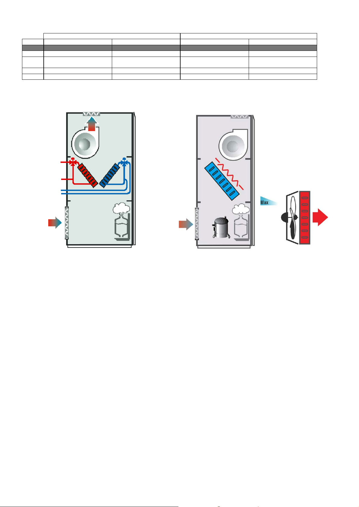
Below is a brief description of the algorithm embedded in the bios for the management of a humidifier with 1 or 2 immersed electrode cylinders.
In this type of humidifier, the steam is produced by boiling the water contained inside the cylinder. This occurs by simply
filling the cylinder with water and applying a voltage to the electrodes. According to the Joule effect, the current will tend
to heat the water until it boils.
V
I
The current that runs through the electrodes in the cylinder depends essentially on the voltage applied to the electrodes, the
conductivity of the water inside the cylinder and the level of the water.
The aim of the algorithm is to maintain the current that runs through the electrodes at a reference value so as to ensure the
percentage of steam production required, according to the readings of the humidity probes and the parameters set by the
user.
During evaporation, the level of the water falls, and as the current is directly proportional to the quantity of water present
in the cylinder, to keep it constant the cylinder would need to be constantly filled with minute quantities of water.
To avoid this, the current is maintained within a certain range around the reference value, by repeated “water
fill/evaporation” cycles.
As well as the level of water in the cylinder, the othe r factor that deter mines the curre nt level is the cond uctiv ity of the wate r inside the cylinder. In fact,
during the fill/evaporation cycles, the conductivity of the water will tend to increase, due to the increase in the concentration of salts in the water. The
conductivity of the water inside the cylinder is measured indirectly, by calculating the time required for a complete evaporation cycle. This time is then
compared against a reference (typical for each cylinder) and, if lower, a certain quantity of water is drained and then the cylinder is topped up with less
conductive mains water.
The humidifier also features a conductivity meter that measures the conductivity of the mains water entering the appliance during the filling
cycles. In the case of high conductivity of the supply water, the control algorithm first signals a pre-alarm (that doesn't stop operation) and
then, if necessary, an alarm (that stops operation). This is essential to avoid the introduction of excessively conductive water into the cylinder,
which may compromise the correct operation of the humidifier.
Another fundamental element, installed at the top of the cylinder, is the high level sensor, used to detect any water or foam.
The high level electrodes may be activated for one of the following reasons:
- over-filling of water in the boiler – when the unit is off – due to a leak in the fill electrovalve;
- high water level when first filling the cylinder;
- high water level following the depletion of the cylinder due to fouling on the plates;
- formation of foam.
In the first case, when the high level sensor is activated, the algorithm stops operation and signals a cylinder full alarm, while in the other three
cases the humidifier responds by draining the water so as to decrease the level.
In the event of repeated activations of the high level sensor, the algorithm evaluates the possibility that the causes may be due to the presence of
foam. In this case, if after having performed a complete washing cycle (complete emptying-complete refill-complete emptying) the high level
sensor continues to be activated, the controller signals a foam alarm (that does not stop operation).
A crucial point in the operation of the humidifier is the control of any excess current levels.
In fact, whenever voltage is applied to the electrodes in the cylinder, after a period of inactivity, there may be short but very intense peaks in
current.
In the current is excessive in this initial period, the algorithm responds by immediately switching off the electrodes and performing a drain
cycle. If the excess current continues, the operation of the humidifier is stopped and a high current alarm is signalled.
The algorithm also controls the drain cycles, signalling a drain alarm if there is no appreciable decrease in current when the drain cycle starts.
Vice-versa, a no water alarm will be signalled if there is no appreciable increase in current when the humidifier is being filled with water.
Carel Cod. +030221421 – Rel. 1.2 – April, 11, 2003
10

Standard air-conditioning units
f
f
3.0 BOARD CONNECTION MANAGEMENT (pLAN)
The pLAN network identifies a physical connection between the boards (pCO1 or pCO2) and the external terminals.
pLAN=p.CO L.ocal A.rea N.etwork. Boards connection in pLAN network allows exchanging variables from a board to another, according to a
logic established by the program, to make them work together in a functional way.
The variables exchanged among the boards are already established by the program, as well as the direction they must follow and from which
they come. Therefore, they cannot be programmed by the user, who must execute the electrical connections only.
Do not execute pCO1 – pCO2 mixed connections, use exclusively boards of the same type.
3.1 pLAN PHYSICAL CONNECTIONS
The pLAN electrical connection among pCO1 or pCO2 boards is executed in parallel with 3 wires, from board to board, by using connector J11;
the data are sent through Rs485 logic; no additional device is required. As usual, terminals shall be connected to the boards by the relevant
telephone cable (code S90CONN*).
3.2 SETTING THE pLAN ADDRESS
For pLAN proper operation, the boards and the external terminals (not the built-in terminals) shall be addressed.
Even if only one board is being used, address 1 shall be set on the board and address 25 shall be set on the external terminal, if any. If the same
address is assigned to two network elements, the pLAN cannot work!
The available addresses range from 1 to 32 (in binary logic), where 32 is the total number of boards + terminals + electronic expansion valves
that can be connected with the pLAN, divided into 8 boards (addresses 1–8), 16 electronic valves (addresses 9–24) and 8 external terminals
(addresses 25–32).
In case external terminals or electronic valves are not used, the boards maximum number (8) keeps unchanged. The addresses to be assigned to
boards, valves and terminals are already established to facilitate installation and are listed in the following paragraph.
3.3 HOW TO ASSIGN THE ADDRESSES
The pLAN addresses are set with binary logic by changing the dip switch position on the back of the external terminals, on pCO2 boards (see
figure below) and inside the electronic valves drivers, with all devices compulsorily not powered; in the pCO1, address is numerical and is
assigned in a different way by an external terminal.
On
Of
microprocessor
On
Of
printer
To read the address of a pCO2 board, external terminal or driver without remembering the binary code by heart, follow this simple rule: if the
switch is in position 1, add up value 1 for switch 1, 2 for switch 2, 4 for switch 3, 8 for switch 4, and so on. Do not add up any values for the
switches in position 0. In the example below, the selected address is: 1 + 2 + 4 + 8 = 15.
Switch1 Switch2 Switch3 Switch4
State off on off on off on off on
P 0 1 0 2 0 4 0 8
Address = P(Sw1)+P(Sw2)+P(Sw3)+P(Sw4)
Carel Cod. +030221421 – Rel. 1.2 – April, 11, 2003
11
pCO2-pCO1 connector

Standard air-conditioning units
dd.
dd.
dd. 27
dd.
dd. 29
dd.
dd.
dd.
3.3.1 SETTING THE pCO1 ADDRESS
Operations to be carried out for pCO1 boards pLAN addressing:
1. Cut pCO1 board power off and connect an external terminal with pLAN address“0”
2. Power pCO1 board keeping terminal buttons Alarm + Up pressed until a screen is displayed
3. After the screen is displayed, carry out the indicated operations, that is key in the numerical pLAN address (1,2,3….) by using buttons
Up and Down, then confirm by pushing Enter
4. Cut pCO1 board power off
5. If required, assign the correct pLAN address to the external terminal, if provided
6. Power pCO1 board.
3.3.2 SETTING THE ADDRESS OF PCO2, EXTERNAL TERMINALS AND VALVE DRIVERS
This paragraph indicates the addresses to be set on pCO2 boards, external terminals and valves drivers. If pCO1 boards are being used, refer to
the previous paragraph as for boards only (as for terminals and drivers, the following indications are valid).
Card 1 Card 2 Card 3 Card 4 Card 5 Card 6 Card 7 Card 8
Add. 1 Add. 2 Add. 3 Add. 4 Add. 5 Add. 6
Terminal 1 Terminal 2 Terminal 3 Terminal 4 Terminal 5 Terminal 6 Terminal 7 Terminal 8
A
25 A
Valve 1 Valve 3 Valve 5 Valve 7 Valve 9 Valve 11 Valve 13 Valve 15
26 A
A
28 A
A
30 A
31 A
32
Valve 2 Valve 4 Valve 6 Valve 8 Valve 10 Valve 12 Valve 14 Valve 16
Each external terminal refers to one board and two electronic valves, that is:
• board ad d. 1 ! valves add. 9/17 ! terminal add. 25,
• board ad d. 2 ! valves add. 10/18 ! terminal add. 26…..
The terminals Menu main screen displays the address of the connected board in the upper right corner. Terminal add. 32 allows controlling all
boards without requiring other terminals or in addition to the other terminals; as a matter of fact, the program allows terminal with add. 32 to
access the parameters of all connected boards, one by one. Passage among the boards can be executed by simply pushing button info.
In all other program screens, the address of the connected board can be known by pushing button info.
3.4 pLAN STATUS
When starting the system, the pLAN network could undergo some problems (failed boards and terminals displays start-up) due to improper
electrical connections or to the fact that incorrect addresses have been assigned. By means of a special screen, the pLAN network state can be
displayed in real time, thus identifying which devices (boards and terminals) are properly connected and addressed. To display the special
screen, push buttons Up-Down-Enter of any network terminal simultaneously for at least 10 sec. After the first 5 seconds, a screen is displayed;
continue for another 5 seconds until the following screen is displayed:
NetSTAT
T: xx
Enter
To Exit
As it can be seen, network addresses from 1 to 32 are displayed, together with a symbol indicating if a terminal (small rectangle) or a board /
valve driver (big rectangle) is concerned. The dash indicates that the board / terminal has incorrect address or is connected improperly. In case
the symbols appear and disappear, it means that pLAN is unstable or, more probably, that repeated addresses are present. The number following
T indicates the address of the terminal being used. The example indicates that the network consists of two boards or valves drivers with address
1, 2, and of three terminals with address 3, 4, 15. After the screen is checked, cut network power off, verify connections and addresses and
power the system again.
3.5 CHECK pLAN ADDRESS
During pCO1 – pCO2 board normal operation, the board pLAN address can be checked at any time by pushing the red button (Prg+Enter in
case a built-in terminal is being used). The information appears on the display first row, covering a part of the displayed screen for 2 seconds.
The pLAN address is always displayed in the M0 Menu screen.
1
9
17
25
8
16
24
32
Carel Cod. +030221421 – Rel. 1.2 – April, 11, 2003
12

Standard air-conditioning units
4.0 FIRST INSTALLATION AND SOFTWARE UPDATING
At first installation, the boards shall be programmed by DOWNLOADING the application program to the Flash buffer memory; this operation
can be performed either using a computer or the hardware key.
4.1 PROGRAM DOWNLOAD FROM HARDWARE KEY
To connect the key to the pCO2 – pCO1, proceed as follows:
1. Switch the pCO2 – pCO1 off and remove the “expansion memory” cover using a screwdriver
2. Place the key selector on
3. Insert the key into the corresponding slot
4. Press Up and Down together and switch the board on
5. Check that the red key LED comes on
6. Wait until the upload request is displayed on the LCD, then release the buttons and confirm by pressing Enter; the data transfer
operation will take approximately 10 seconds
7. Switch the pCO2 – pCO1 off, remove the key, place the cover in its original position and switch the board back on again
8. The board will now work with the program transferred from the key.
4.2 PROGRAM DOWNLOAD FROM COMPUTER
Use the kit code PC485KIT00 and the WinLOAD 32 program, proceeding as follows:
1. Connect the converter (RS232/RS485) to the mains using the transformer provided in the kit
2. Connect the converter to a free serial port on the PC, using the serial cable provided in the kit
3. Connect the converter to connector J10 on the pCO2 – pCO1 using a telephone cable (code S90CONN00*)
4. Install Winload, if Winload is not already installed on the PC
5. Run WinLOAD32 on the PC, with the board off
6. Enter in the number of the PC serial port in the field “COMM” (1 for COM1, 2 for COM2)
7. Enter “0” in the field “pCO² ADD.”
8. Switch the board on
9. Wait 30 seconds until the message “OFF LINE” becomes “ON LINE” in the WinLOAD32 program, in the lower left, or until the
yellow LED next to the dipswitch on the board starts flashing; now enter the actual board pLAN address value in the field “pCO²
ADD”; a bl u e l i ght i n the Winloa d pro gram , in t h e bottom c e ntre of t h e window , will start f lashing.
10. In WinLOAD32, select “Upload” and then “Application”
11. Select the folder containing the application program source files
12. Use CTRL to select a series of *.iup files, if needing to load a series of languages to the pCO2-pCO1. Also select the *.blb files (for
non-pLAN applications) or the flash1.bin file in the program being loaded (for pLAN applications)
13. Click “UPLOAD” to start the file download procedure, which will take approximately 1 to 5 minutes, depending on the number of
*.iup files selected and the size of the various files
14. Wait until the message “Upload OK” appears in the progress bar
15. Disconnect the telephone cable between the board and converter; connect the external terminal (if featured), then switch the board off
and on again
NOTE: if a pLAN network with a series of boards is used, the program can be installed on the other boards without repeating the operations:
after installing the program on the first board, simply repeat steps from 8 to 14, entering the new board addresses each time in the field “pCO²
ADD” in the WinLOAD32 program.
4.3 INSTALLING THE DEFAULT PARAMETERS
Default parameters are the values assigned by CAREL to the application program main operative parameters. Parameters are assigned
automatically when executing the DOWNLOAD operation as described above. Parameters indicate timing, set points, differentials, etc… (refer
to the complete list of default values in par. 6.0).
After installing default values, the parameters can be modified within the prescribed values range.
If required, parameters can also be installed manually by the user, at any time, by the external or built-in terminal.
Operations to be carried out for default parameters manual installation:
1. Push buttons MENU + PROG and key in the Manufacturer password (1234), then push Enter
2. By pushing button Down three times, move the cursor on “INITIALISATION” (last row), then push ENTER
3. The parameters installation screen is displayed; to install, push ENTER and key in the Manufacturer password
4. WARNING: we recommend extreme care since this operation deletes all the installed parameters from the memory and replaces them
by the default parameters – after this operation, parameters cannot be restored.
5. After pushing ENTER, message “PLEASE WAIT” is displayed for some seconds.
4.4 LANGUAGE SELECTION
English is the language automatically selected, but it can be changed into: Italian, French, German, Spanish. To modify the language, operate as
follows:
1. Push buttons MENU + PROG and key in the Manufacturer password (1234), then push Enter
2. By pushing button Down three times, move the cursor on “INITIALISATION” (last row), then push ENTER
3. The parameters installation screen is displayed; push button Down three times
4. The screen with the language selection parameter is displayed, push Enter to scroll and select the language.
Carel Cod. +030221421 – Rel. 1.2 – April, 11, 2003
13

Standard air-conditioning units
5.0 CONFIGURATION LIST
The pCO1/pCO2 small/medium boards allow managing both “ED” direct expansion and “CW” water coil air-conditioning units. When started,
the program recognises the board type and size, consequently prearranging inputs and outputs, also based on the air-conditioning unit type (ED
or CW) established in the Manufacturer branch. The following tables indicate inputs and outputs configurations in the possible combinations.
The multiple items (xxx / xxx / …) indicate different inputs and outputs purposes; selection is carried out by Manufacturer screens branch
parameters. As for wiring harness, refer to the technical manual of the pCO1 and pCO2 boards.
5.1 DIGITAL INPUTS
N. pCO1 – pCO2 SMALL pCO1 – pCO2 MEDIUM pCO1 – pCO2 SMALL pCO1 – pCO2 MEDIUM
ID 1 C1 alarm / C1 low pressure C1 alarm Flooding / fire alarm Flooding alarm
ID 2 C2 alarm / C1 high pressure C2 alarm Summer – Winter selection Summer – Winter selection
ID 3 Heater 1 thermal alarm Heater 1 thermal alarm Heater 1 thermal alarm Heater 1 thermal alarm
ID 4 Heater 2 thermal alarm Heater 2 thermal alarm Heater 2 thermal alarm Heater 2 thermal alarm
ID 5 Fire / filter / flooding alarm Dirty filters alarm Dirty filters alarm Dirty filters alarm
ID 6 Fan thermal alarm Fan thermal alarm Fan thermal alarm Fan thermal alarm
ID 7 Air flow controller alarm Air flow controller alarm Air flow controller alarm Air flow controller alarm
ID 8 Remote On-Off Remote On-Off Remote On-Off Remote On-Off
ID 9 --- C1 low pressure alarm --- Auxiliary alarm
ID 10 --- C2 low pressure alarm --- Water flow controller alarm
ID 11 --- Humidifier water level --- Humidifier water level
ID 12 --- Fire / flooding alarm --- Fire alarm
ID 13 --- C1 cond. fan thermal alarm --- --ID 14 --- C2 cond. fan thermal alarm --- ---
5.2 ANALOGUE INPUTS
N. pCO1 – pCO2 SMALL pCO1 – pCO2 MEDIUM pCO1 – pCO2 SMALL pCO1 – pCO2 MEDIUM
B 1 Ambient humidity Ambient humidity Ambient humidity Ambient humidity
B 2 C1 high press. / C1 cond. temp. /
Outlet temperature (pCO2)
B 3 C2 high press. /
C2 cond. temp. /
Recovery temperature
B 4 External temperature External temperature (pCO2)
B 5 Ambient temperature Ambient temperature Ambient temperature Ambient temperature
B 6 Outlet temperature (pCO1)
B 7 --- Humidif. conductibility (pCO2)
B 8 --- Humidifier current (pCO2)
5.4 DIGITAL OUTPUTS
N. pCO1 – pCO2 SMALL pCO1 – pCO2 MEDIUM pCO1 – pCO2 SMALL pCO1 – pCO2 MEDIUM
DO 1 Outlet fan Outlet fan Outlet fan Outlet fan
DO 2 Compressor 1 Compressor 1 Cold valve opening / single Cold valve opening / single
DO 3 Compressor 2 Compressor 2 Cold valve closing / single Cold valve closing / single
DO 4 Resist.1 / Warm valve opening Resist.1 / Warm valve opening Resist.1 / Warm valve opening Resist.1 / Warm valve opening
DO 5 Resist.2 / Warm valve closing Resist.2 / Warm valve closing Resist.2 / Warm valve closing Resist.2 / Warm valve closing
DO 6 Dehumidification Dehumidification Dehumidification Dehumidification
DO 7 Recovery
DO 8 Generic alarms Serious alarms Generic alarms Serious alarms
DO 9 --- C1 cond. fan / C1 capacity
DO 10 --- C2 cond. fan / C2 capacity
DO 11 --- Humidification --- Humidification
DO 12 --- Humidifier water load --- Humidifier water load
DO 13 --- Humidifier water drain --- Humidifier water drain
ED CW
ED CW
C1 high press. /
C1 cond. temp.
C2 high press. / C2 cond. temp. /
Recovery temperature (pCO2) /
Humidif. conductibility (pCO1)
Humidifier current (pCO1)
Outlet temperature FREE FREE
Recovery temperature (pCO1)
External air temperature (pCO1)
ED CW
Recovery / N
control
control
on-serious alarms
Outlet temperature Outlet temperature
Recovery temperature Recovery temperature (pCO2) /
External temperature External temperature (pCO2) /
--- Humidif. conductibility (pCO2)
--- Humidifier current (pCO2)
Recovery
--- ---
--- ---
Humidif. conductibility (pCO1)
Humidifier current (pCO1)
Recovery / Non-serious alarms
Carel Cod. +030221421 – Rel. 1.2 – April, 11, 2003
14
Standard air-conditioning units
5.3 ANALOGUE OUTPUTS
N. pCO1 – pCO2 SMALL pCO1 – pCO2 MEDIUM pCO1 – pCO2 SMALL pCO1 – pCO2 MEDIUM
AO 1 Outlet fan / Recovery valve Outlet fan / Recovery valve Cold valve / single Cold valve / single
AO 2 Warm valve Warm valve /
AO 3 Condensing fan 1 Condensing fan 1 --- --AO 4 Condensing fan 2 Condensing fan 2 Outlet fan Outlet fan
ED CW
Humidification
Warm valve / Recovery valve Warm valve / Recovery valve /
Humidification
5.5 CLOSE CONTR. UNIT WITH COILS CLOSE CONTR. UNIT WITH DIRECT EXPANS. COIL
Carel Cod. +030221421 – Rel. 1.2 – April, 11, 2003
15

Standard air-conditioning units
6.0 LIST OF PARAMETERS AND DEFAULT VALUES
The table below lists the parameters in the program, together with the following information: screen code (the screen code is displayed at the top
right) to assist the identification of the parameter, the default value, the minimum and maximum limits (range), and the unit of measure.
To find a specific parameter on the display, proceed as follows:
• Identify the parameter in the table below and the corresponding screen code
• Using the list of the screens (following paragraph) and the screen code, access the screen on the terminal
PARAMETER DESCRIPTION SCREEN DEFAULT USER
VALUE
RANGE UOM
Select display language A0 English En,It,Fr,De,Sp
Manual humidifier drain with unit ON A4 No No-Yes
Enter password A6 1234 0-9999
Modify outlet fan operating hours A7 0 0-99 . 0-999 hours
Modify compressor 1 operating hours A7 0 0-99 . 0-999 hours
Modify compressor 2 operating hours A7 0 0-99 . 0-999 hours
Device operating hour threshold A8 99 0-99 hours x 1000
Humidity probe calibration A9 0 -9.9 - 9.9 %RH
Condenser 1 pressure probe calibration A9 0 -9.9 - 9.9 bar
Condenser 2 pressure probe calibration A9 0 -9.9 - 9.9 bar
Ambient temperature probe calibration Aa 0 -9.9 - 9.9 ºC / ºF
Outside temperature probe calibration Aa 0 -9.9 - 9.9 ºC / ºF
Outlet temperature probe calibration Aa 0 -9.9 - 9.9 ºC / ºF
Recovery temperature probe calibration Ab 0 -9.9 - 9.9 ºC / ºF
Condenser 1 temperature probe calibration Ab 0 -9.9 - 9.9 ºC / ºF
Condenser 2 temperature probe calibration Ab 0 -9.9 - 9.9 ºC / ºF
Manual activation of digital outputs 1 – 2 – 3 Ac Off Off-on
Manual activation of digital outputs 4 – 5 – 6 Ad Off Off-on
Manual activation of digital outputs 7 – 8 Ae Off Off-on
Manual activation of digital outputs 9 – 10 Af Off Off-on
Manual activation of modulating outputs 1 – 2 Ag 0 0-10.0 Volt
Manual activation of modulating outputs 3 – 4 Ah 0 0-10.0 Volt
Manual activation of pre wash built-in humidifier Ai No No-Yes
Manual activation of total water drain built-in humidifier. Ai No No-Yes
Driver 1 valve control mode Aj Automatic Auto-Man.
Driver 1 valve manual opening steps Aj 0 0-9999 Steps
Driver 2 valve control mode Ak Automatic Auto-Man.
Driver 2 valve manual opening steps Ak 0 0-9999 Steps
Driver 1 manual release on start-up Al No No-Yes
Driver 2 manual release on start-up Am No No-Yes
Enter new Maintenance password An 1234 0-9999
Cyclical print interval H1 24 0-999 hours
Send immediate print H1 No No-Yes
Hour setting K0 current hour 0-23 Hours
Minute setting K0 current minutes 0-59 minutes
Day setting K0 current day 1-31
Month setting K0 current month 1-12
Year setting K0 current year 0-99
Enter Clock password K1 1234 0-9999
Enable temperature / humidity / On-Off time bands K2 No No-Yes
Start and end hour for On-Off time bands F1-1 and F1-2 K3 9 / 13 / 14 / 21 0-23 hours
Start and end minutes for On-Off time bands F1-1 and F1-2 K3 0 / 0 / 0 / 0 0-59 minutes
Start and end hour for On-Off time band F2 K4 14 / 21 0-23 hours
Start and end minutes for On-Off time band F2 K4 0 / 0 0-59 minutes
Select On-Off time bands (F1,F2,F3,F4) for each day K5 F2 F1-F4
Start hour temperature bands 1 and 2 K6 0 / 6 0-23 hours
Start minutes temperature bands 1 and 2 K6 0 / 0 0-59 minutes
Set point temperature bands 1 and 2 K6 23.0 see P1 ºC / ºF
Start hour temperature bands 3 and 4 K7 12 / 18 0-23 hours
Start minutes temperature bands 3 and 4 K7 0 / 0 0-59 minutes
Carel Cod. +030221421 – Rel. 1.2 – April, 11, 2003
16

Standard air-conditioning units
PARAMETER DESCRIPTION SCREEN DEFAULT USER
RANGE UOM
VALUE
Set point temperature bands 3 and 4 K7 23.0 see P1 ºC / ºF
Start hour humidity bands 1 and 2 K8 0 / 6 0-23 hours
Start minutes humidity bands 1 and 2 K8 0 / 0 0-59 minutes
Set point humidity bands 1 and 2 K8 23.0 see P2 %RH
Start hour humidity bands 3 and 4 K9 12 / 18 0-23 hours
Start minutes humidity bands 3 and 4 K9 0 / 0 0-59 minutes
Set point humidity bands 3 and 4 K9 23.0 see P2 %RH
Enter new Clock password Ka
Temperature set point S1 23.0 see P1 ºC / ºF
Humidity set point S1 50.0 see P2 %RH
Enter user password P0 1234 0-9999
Minimum and maximum temperature set point limits P1 -99.9 / 99.9 -999.9-999.9 ºC / ºF
Minimum and maximum humidity set point limits P2 0.0 / 100.0 0.0-100.0 %RH
Proportional temperature bands in Heating and cooling P3 3.0 / 3.0 0.0-100.0 ºC / ºF
Temperature dead zone P3 0,0 0.0-99.9 ºC / ºF
Proportional bands in Humidification and Dehumidification P4 2.0 / 2.0 0.0-99.9 %RH
Maximum production allowed, built-in humidifier P4 Rated output 20% -100% of rated
Switch unit off from button P5 No No-Yes
Enable remote On-Off digital input P5 No No-Yes
Recovery water temperature set point P6 12,0 0-99.9 ºC / ºF
Enable compensation function P7 No No-Yes
Outside air compensation set point P7 25.0 -999.9-999.9 ºC / ºF
Outside air compensation differential P7 3.0 -999.9-999.9 ºC / ºF
Offset maximum of compensation of the set of temperature P7 2.0 -999.9-999.9 ºC / ºF
High and low ambient temperature alarms offset P8 10.0 / 10.0 -999.9-999.9 ºC / ºF
High and low ambient humidity alarms offset P9 20.0 / 30.0 0-100,0 %RH
Enable outlet limit function Pa No No-Yes
Outlet air set point for the limitation function Pa 15.0 -999.9-999.9 ºC / ºF
Outlet air differential for the limitation function Pa 5.0 -999.9-999.9 ºC / ºF
Assign type of alarm Serious/Minor AL01-AL20 Pb All N N-Y
Assign type of alarm Serious/Minor AL21-AL40 Pc All N N-Y
Assign type of alarm Serious/Minor AL41-AL60 Pd All N N-Y
Assign type of alarm Serious/Minor AL61-AL67 Pe All N N-Y
Board identification number for supervisory network Pf 1 0-200
Board communication speed for supervisory network Pf 1200 1200-19200 Baudrate
Serial communication protocol Pf Carel Carel,Modbus,
Telephone numbers entered on analogue modem Pg 1 1-4
Enter telephone numbers on analogue modem Pg 0 0…9,#,*,@,ˆ
Number of rings for analogue modem Ph 0 0-9
Password for supervisor remote connection Ph 0 0-9999
Type of analogue modem Ph T one Tone-Pulse
Number of rings for GSM modem Pi 0 0-9
Password to write SMS text message Pi 0 0-9999
Destination GSM telephone number Pi 0 0…9,#,*,@,ˆ
Enter new user password Pj 1234 0-9999
kg/h
output
Lon,RS232,Gsm
Enter manufacturer password Z0 1234 0-9999
CONFIGURATION →
Enable BMS C0 No No-Yes
Enable printer C0 No No-Yes
Select unit of measure for temperature probes and parameters C0 ºC ºC-ºF
Enable clock board (pCO1 only) C0 No No-Yes
Type of unit C1 ED ED-CW
Select refrigerant
Number of compressors C2 2 1-2
Enable compressor capacity-control steps C2 No No-Yes
Carel Cod. +030221421 – Rel. 1.2 – April, 11, 2003
+
C1
R134a
R22,R134a,
R404a,R407C,
R410A
17

Standard air-conditioning units
PARAMETER DESCRIPTION SCREEN DEFAULT USER
RANGE UOM
VALUE
Heating mode C2 Heaters Heaters-Coil
Humber of heaters C2 2 0-3
Type of valve for heating coil C2 0-10Volt 0-10V/3 pos.
Type of coil C3 C/H C/H-Cool
Type of valve for the coil C3 0-10Volt 0-10V/3 pos.
Heating mode C3 Heaters Heaters-Coil 2
Humber of heaters C3 2 0-3
Type of valve for heating coil C3 0-10Volt 0-10V/3 pos.
Digital input 5 configuration
Digital input 12 configuration C5 Fire alarm Fire alarm,
Digital input 1 configuration C6 Fire alarm Fire alarm,
Digital output 7 configuration C7 Recovery valve Recovery valve, minor
Probe 2 input configuration
Probe 3 input configuration
Modulating output 1 configuration Ca Modulating fan Recovery valve,
Enable modulating 0-10 humidifier output Ca No No-Yes
Modulating output 2 configuration Cb Recovery valve Recovery valve, 0-10V
Enable recovery coil Cc No No-Yes
Enable modulating outlet fan Cc No No-Yes
Enable condenser function Cd No No-Yes
Type of condenser Cd Single Single-Sep.
Select type of fans Cd Inverter Inverter-Step
Select number of On-Off fans Cd 1 1-2
Maximum voltage threshold for Triac Ce 92 0-100 %
Minimum voltage threshold for Triac Ce 70 0-100 %
Duration of Triac impulse Ce 2 0-10 m seconds
Logic of the dehumidification contact Cf NO NO-NC
Number of compressors enabled for dehumidification Cf 0 0-2
Enable cooling coil for dehumidification Cf No No-Yes
Enable built-in humidifier Cf No No-Yes
Type of humidifier Cg Type 8 1-44 (see 2.1)
Maximum production Cg 70 0-100 %
Optional card model Cg PCOUMID000
Enable humidity probe Ch No No-Yes
Type of signal from the humidity probe Ch 0-1V 0-1V,0-10V,
Minimum and maximum value measured by the humidity
probe
Enable pressure probe 1 Ci No No-Yes
Type of signal pressure probe 1 Ci Current 0-1V,0-10V,
Minimum and maximum value pressure probe 1 Ci 0.0 / 30.0 -20.0 - 50.0 Bar
Enable pressure probe 2 Cj No No-Yes
Type of signal pressure probe 2 Cj Current 0-1V,0-10V,
Minimum and maximum value pressure probe 2 Cj 0.0 / 30.0 -20.0 - 50.0 Bar
Type of signal from ambient temperature probe Ck NTC NTC-PT100
Enable outlet probe Ck No No-Yes
Type of signal from outlet temperature probe Ck NTC NTC-PT100
Enable outside temperature probe Cl No No-Yes
Type of signal from outside temperature probe Cl NTC NTC-PT100
Enable recovery probe Cl No No-Yes
Type of signal from recovery temperature probe Cl NTC NTC-PT100
Enable condenser 1 temperature probe Cm No No-Yes
Type of signal from condenser 1 temperature probe Cm NTC NTC-PT100
Enable condenser 2 temperature probe Cm No No-Yes
Type of signal from condenser 2 temperature probe Cm NTC NTC-PT100
pLAN connection class, board 1
pLAN connection class, boards 2 – 3
pLAN connection class, boards 4 – 6 Co
Carel Cod. +030221421 – Rel. 1.2 – April, 11, 2003
C4
C8
C9
Ch 0.0 / 100.0 0-100,0 %RH
Cn
Cn
Filter alarm
Pressure 1
Pressure 2
Present-no rot.
Not present
Not present
Flood alarm, Filter
alarm, Fire alarm
Flood alarm
Flood alarm
alarms
Pressure 1,
Cond. temp.1,
Outlet temp.
Pressure 2,
Cond. temp. 2,
Recovery temp
modulating fan
humid.
PCOUMID200-
PCOUMID000
current
current
current
Present-rot., Present-no
rot., Not present
Present-rot., Present-no
rot., Not present
Present-rot., Present-no
rot., Not present
18

Standard air-conditioning units
PARAMETER DESCRIPTION SCREEN DEFAULT USER
RANGE UOM
VALUE
pLAN connection class, boards 7 – 8 Cp
Enable compressors/cooling coil together with recovery coil G0 No No-Yes
PARAMETERS →
Enable FIFO compressor rotation G1 No No-Yes
Type of temperature control G1 Proportional Prop.-P+I
Logic of the capacity-control contact G1 NC NC-NO
Starting point to open modulating valve in cooling (or single
valve) with recovery (see G0)
Starting and end point to open modulating valve in cooling (or
single valve)
Starting point to open 3 position valve in cooling (or single
valve) with recovery (see G0)
Starting and end point to open 3 position valve in cooling (or
single valve)
Starting and end point to open modulating valve in heating G4 0.0 / 100.0 0.0-100.0 %
Starting and end point to open 3 position valve in heating G5 0.0 / 100.0 0.0-100.0 %
Starting and end point to open modulating valve in recovery G6 0.0 / 100.0 0.0-100.0 %
Minimum and maximum modulating fan speed G7 0.0 / 100.0 0.0-100.0 Volt
Outlet fan speed during dehumidification G7 5,0 0.0-100.0 Volt
Starting and end point to open modulating humid. output G8 0.0 / 100.0 0.0-100.0 %
Temperature differential to stop dehumidification G9 5.0 0-99.9 ºC / ºF
Temperature offset to restart dehumidification G9 4.0 0-99.9 ºC / ºF
Disable water drain for set point reduction Ga No No-Yes
Disable drain for extended humidifier standby Ga No No-Yes
Disable minor humidifier alarm messages Ga No No-Yes
High conductivity pre-alarm threshold Gb 1500 0-2000 uS/cm
High conductivity alarm delay Gb 2000 0-2000 uS/cm
Drain time as % of H3 (see humidifier manual) Gc 100 50-200 %
Evaporation time as % of H4 (see humidifier manual) Gc 100 50-200 %
High pressure alarm set point Gd 23.5 -99.9 - 99.9 bar
High pressure alarm differential Gd 1.0 -99.9 - 99.9 bar
Condensing (pressure) set point Ge 14.0 -99.9 - 99.9 bar
Condensing (pressure) differential Ge 2.0 -99.9 - 99.9 bar
Modulating condensing fan speed-up time Ge - Gf 2 0-999 seconds
Condensing (temperature) set point Gf 55.0 -99.9 - 99.9 ºC / ºF
Condensing (temperature) differential Gf 1.0 -99.9 - 99.9 ºC / ºF
Minimum and maximum mod. cond. fan speed Gg 0.0 / 10.0 0-10,0 Volt
Enable high pressure alarm Prevent function Gh - Gi No No-Yes bar
Prevent function set point (pressure) Gh 20.0 -99.9 - 99.9 Bar
Prevent function differential (pressure) Gh 2.0 -99.9 - 99.9 bar
Prevent function set point (temperature) Gi 70.0 -99.9 - 99.9 ºC / ºF
Prevent function differential (temperature) Gi 1.0 -99.9 - 99.9 ºC / ºF
Enable Carel network Master Control function Gj No No-Yes
Rotation mode for units in pLAN network
Number of units set in Standby mode
Automatic rotation interval for units in pLAN Gk 24 1-240 Hours
Automatic rotation hours for units in pLAN network Gl 22 0-23 hours
Automatic rotation minutes for units in pLAN network Gl 00 0-59 minutes
Interval in days for automatic rotation in pLAN network Gl 3 1-7 days
Enable Force units in pLAN network Gm No No-Yes
Forcing delay for low and high ambient temperature Gm 3 / 3 0-999 minutes
Low ambient temp. diff. for forcing units in network Gn 8 0-99.9 ºC / ºF
Low ambient temp. offset for forcing units in network Gn 4 0-99.9 ºC / ºF
High ambient temp. diff. for forcing units in network Go 8 0-99.9 ºC / ºF
High ambient temp. offset for forcing units in network Go 4 0-99.9 ºC / ºF
CAREL EXV DRIVERS →
Number of drivers connected F0 0 0-2
Enable backup battery driver 1 F0 No No-Yes
Enable backup battery driver 1 F0 No No-Yes
Type of valve circuit 1 F1 10 (Carel) 0-11 (see 1.5)
Superheating set point circuit 1 F1 6.0 2,0-50,0 ºC
Dead band circuit 1 F1 0 0-9.9 ºC
Type valve circuit 2 F2 10 (Carel) 0-11 (see 1.5)
Superheating set point circuit 2 F2 6.0 2.0-50.0 ºC
Dead band circuit 2 F2 0 0-9.9 ºC
PID control – proportional gain circuit 1 F3 2.5 0.0-99.9
PID control – integration time circuit 1 F3 25 0-999 seconds
PID control – derivative time circuit 1 F3 5,0 0.0-99.9 seconds
G2 50.0 0.0-100.0 %
G2 0.0 / 100.0 0.0-100.0 %
G3 50,0 0.0-100.0 %
G3 0.0 / 100.0 0.0-100.0 %
Gk
Gk
Not present
Automatic
0
Present-rot., Present-no
rot., Not present
Automatic,
Time bands,
Operating hours
0-No. unit in Present-
rotation mode
Carel Cod. +030221421 – Rel. 1.2 – April, 11, 2003
19

Standard air-conditioning units
PARAMETER DESCRIPTION SCREEN DEFAULT USER
RANGE UOM
VALUE
PID control – proportional gain circuit 2 F4 2.5 0.0-99.9
PID control – integration time circuit 2 F4 25 0-999 seconds
PID control – derivative time circuit 2 F4 5,0 0.0-99.9 seconds
Threshold for low superheat protection circuit 1 F5 4.0 -4.0 - 10.0 ºC
Prot. threshold integration time, low superheat circuit 1 F5 10 0-255 seconds
Threshold for low superheat protection circuit 2 F6 4.0 -4.0 - 10.0 ºC
Prot. threshold integration time, low superheat circuit 2 F6 10 0-255 seconds
Percentage ratio between cooling capacity and Driver capacity
C 1
Percentage ratio between cooling capacity and Driver capacity
C 2
LOP threshold F8 -40.0 -70.0 - 50.0 ºC
LOP threshold integration time F8 40 0-255 seconds
MOP start delay F9 30 0-500 seconds
MOP threshold F9 40.0 -50.0 - 99.9 ºC
MOP threshold integration time F9 40 0-255 seconds
High condensing temp. protection threshold Fa 75.0 0-99.9 ºC
Integration time for high condensing temp. threshold Fa 40 0-255 seconds
High suction temperature threshold Fb 30.0 0-100.0 ºC
Custom Valve: minimum steps Fc 0 0-8100
Custom Valve: maximum steps Fc 1600 0-8100
Custom Valve: closing steps Fd 3600 0-8100
Custom Valve: return steps Fd 0 0-8100
Custom Valve: enable extra step in opening Fe No No-Yes
Custom Valve: enable extra step in closing Fe No No-Yes
Custom Valve: operating current Ff 250 0-1000 mA
Custom Valve: holding current Ff 100 0-1000 mA
Custom Valve: frequency Fg 100 32-330 Hertz
Custom Valve: duty cycle Fg 50 0-100 %
Minimum evaporation pressure probe value Fh -0.5 -9.9 - 10.0 Bar
Maximum evaporation pressure probe value Fh 7.0 3.5 - 40.0 Bar
Low superheating alarm delay Fi 0 0-3600 seconds
High suction temperature alarm delay Fi 0 0-3600 seconds
LOP alarm delay Fj 0 0-3600 seconds
MOP alarm delay Fj 0 0-3600 seconds
TIMES →
Outlet fan start and stop delay T0 10 / 20 0-999 seconds
Integration time for P+I temperature control T1 600 0-999 seconds
Travel time for 3 position valve T1 180 0-999 seconds
Low pressure alarm delay T2 180 0-999 seconds
High-low temperature-humidity alarm delays T2 600 0-999 seconds
Alarm relay 7 activation delay, minor alarm T3 0 0-999 seconds
Alarm relay 8 activation delay, serious alarm T3 0 0-999 seconds
Air flow switch alarm delay T4 10 0-999 seconds
Water flow switch alarm delay T4 10 0-999 seconds
Minimum compressor off time T5 180 0-999 seconds
Minimum compressor on time T5 60 0-999 seconds
Delay between compressor starts T6 360 0-999 seconds
Minimum delay between starts of different compressors T6 10 0-999 seconds
Cap. control activation delay T7 10 0-999 seconds
Heater start delay T8 3 0-999 seconds
INITIALISATION →
Enter password for reset Default values function V0 1234 0-9999
Delete BASIC alarm log V1 No No-Yes
Enter new manufacturer password V2 1234 0-9999
F7 60 0-100 %
F7 60 0-100 %
Carel Cod. +030221421 – Rel. 1.2 – April, 11, 2003
20

Standard air-conditioning units
7.0 ALARMS
The alarms managed by the program safeguard soundness of the connected devices and provide signals in case the control parameters have
exceeded the normal values or the board is faulty. The alarms originate from alarm digital inputs, probes or board. Their effect ranges from the
simple block signalling of one or more devices to the air-conditioning unit stop. Many alarms are subject to programmable delay times.
When an alarm state is identified, the following signals occur:
• the buzzer incorporated into the external terminal (not provided for on the built-in terminal) turns on
• the red LED under button ALARM turns on
• abbreviation AL starts blinking on the Menu screen
Pushing button Alarm, the buzzer switches off and the alarm screen is displayed. If more alarms are active, the screen of the first alarm is
displayed; the other alarms can be displayed by using the arrow buttons. If other buttons are pressed, the alarm screens are left but they keep
stored and are displayed again whenever the Alarm button is pressed.
To rearm the alarms and delete t he message manu ally, simply move the cursor on the alarm screens and push button Alarm again; if the alarm
causes have disappeared (digital inputs rearmed, temperature within the normal values, etc…), the screens disappear, the red led switches off
and message “NO ALARM ACTIVE” is displayed. If the cause of one or more alarms is still active, the disabled alarms only disappear,
whereas the other alarms keep displayed and the buzzer and the red led switch on again.
Alarms are divided into two categories: manually-rearmed alarms or automatically-rearmed alarms.
The manually-rearmed alarms require alarm screen deleting (as described above) to restart the devices or the air-conditioning unit. The
automatically-rearmed alarms unlock the device or restart the air-conditioning unit after the cause has disappeared, but the alarm screen keeps
stored in the memory.
7.1 ALARM RELAYS
The medium boards provide a relay for the serious alarms and another relay for the non-serious alarms. The small boards include all alarms in
the only available relay.
The non-serious alarm relay is closed in case of any type of alarm; the serious alarm relay is closed in case of serious alarms only. Each
managed alarm may be identified as serious or non-serious, consequently allowing to determine which relay shall be enabled. The delay time
can be determined for both relays before closing.
Carel Cod. +030221421 – Rel. 1.2 – April, 11, 2003
21

Standard air-conditioning units
7.2 TABLE OF ALARMS
CODE DESCRIPTION DELAY UNIT OFF DISABLED DEVICES
A01 Compressor 1 general alarm - - Compressor 1
A02 Compressor 2 general alarm - - Compressor 2
A03 Compressor 1 low pressure see T2 - Compressor 1
A04 Compressor 2 low pressure see T2 - Compressor 2
A05 No air flow see T4 yes All
A06 Outlet fan thermal - yes All
A07 Heater 1 thermal - - Heater 1
A08 Heater 2 thermal - - Heater 2
A09 Fire / Smoke detection - yes All
A10 Dirty filters - - A11 High ambient temperature see T2 - A12 Low ambient temperature see T2 - A13 High ambient humidity see T2 - A14 Low ambient humidity see T2 - A15 Compressor 1 working hours threshold reached - - A16 Compressor 2 working hours threshold reached - - A17 Outlet fan working hours threshold reached - - A18 Ambient temperature probe faulty or disconnected 60 sec (fixed) - A19 Recovery water temperature probe faulty or disconnected 60 sec (fixed) - A20 External air temperature probe faulty or disconnected 60 sec (fixed) - A21 Outlet air temperature probe faulty or disconnected 60 sec (fixed) - A22 Ambient humidity probe faulty or disconnected 60 sec (fixed) - A23 Condenser 1 pressure probe faulty or disconnected 60 sec (fixed) - A24 Condenser 2 pressure probe faulty or disconnected 60 sec (fixed) - A25 Condenser 1 temperature probe faulty or disconnected 60 sec (fixed) - A26 Condenser 2 temperature probe faulty or disconnected 60 sec (fixed) - A27 High humidifier current - - Humidifier
A28 No water inside humidifier cylinder ? - A29 No current in humidifier ? - A30 Clock card not present / faulty - - A31 Circuit 1 high pressure - - Compressor 1
A32 Circuit 2 high pressure - - Compressor 2
A33 Water under floor - yes All
A34 Auxiliary alarm - - A35 Compressor 1 high pressure + thermal - - Compressor 1
A36 Humidifier working hours threshold reached - - A37 Compressor 2 high pressure + thermal - - Compressor 2
A38 Condensing fan 1 thermal - - Condensing fan 1
A39 Condensing fan 2 thermal - - Condensing fan 2
A40 No water flow see T4 yes All
AL41 pLAN disconnected 60 sec (fixed) - AL42 Driver 1 alarm, probes faulty or disconnected - - Compressor 1
AL43 Driver 1 EEPROM faulty or damaged - - Compressor 1
AL44 Driver 1 valve motor faulty or damaged - - Compressor 1
AL45 Driver 1 alarm, battery discharged or faulty - - AL46 Driver 1 high evaporation pressure (MOP) See Fj - AL47 Driver 1 low evaporation pressure (LOP) See Fj - AL48 Driver 1 low superheating See Fi - Compressor 1
AL49 Driver 1 valve not closed during blackout - - Compressor 1
AL50 Driver 1 high suction pressure See Fi - AL51 Driver 2 alarm, probes faulty or disconnected - - Compressor 2
AL52 Driver 2 EEPROM faulty or damaged - - Compressor 2
AL53 Driver 2 valve motor faulty or damaged - - Compressor 2
AL54 Driver 2 alarm, battery discharged or faulty - - AL55 Driver 2 high evaporation pressure (MOP) See Fj - AL56 Driver 2 low evaporation pressure (LOP) See Fj - AL57 Driver 2 low superheating See Fi - Compressor 2
AL58 Driver 2 valve not closed during blackout - - Compressor 2
AL59 Driver 2 high suction pressure See Fi - -
AL60 Built-in humidifier: high conductivity alarm
AL61 Built-in humidifier: high conductivity pre alarm
AL62 Built-in humidifier: low steam production - - Humidifier
AL63 Built-in humidifier: water drain alarm - - Humidifier
AL64 Built-in humidifier: cylinder full alarm - - Humidifier
AL65 Built-in humidifier: cylinder being depleted signal - - AL66 Built-in humidifier: presence of foam - - AL67 Built-in humidifier: cylinder depleted - - -
See threshold
Gb: delay 1h
See threshold
Gb: delay 1h
- Humidifier
- -
Carel Cod. +030221421 – Rel. 1.2 – April, 11, 2003
22

Standard air-conditioning units
8.0 SCREENS
The screens are divided into five categories:
• USER screens not protected by password: present in all branches but “prog” and “menu+prog”, they show probes values, alarms, devices
working hours, hour and date; these screens also allow setting the temperature and humidity set points and regulating the clock. In the
following parameters table, they are indicated with symbol “!”.
• USER screens protected by password (1234, modifiable): these screens are accessed by pushing button “prog” and allow setting the main
functions (timing, sets, differentials) of the connected devices; the screens referring to non-available functions are not displayed. In the
following parameters table, they are indicated with symbol “"”.
• SERVICE screens protected by password (1234, modifiable): these screens are accessed by pushing button “maintenance” and allow
checking the devices periodically, calibrating the connected probes, modifying the working hours and managing the devices manually. In
the following parameters table, they are indicated with symbol “#”.
• CLOCK screens protected by password (1234, modifiable): these screens are accessed by pushing button “clock” and allow setting and
enabling the temperature and humidity time bands. In the following parameters table, they are indicated with symbol “$”.
• MANUFACTURER screens protected by password (1234, modifiable): these screens are accessed by pushing buttons “menu+prog” and
allow configuring the air-conditioning unit, enabling the main functions and selecting the connected devices. In the following parameters
table, they are indicated with symbol “%”.
8.1 LIST OF THE SCREENS
The following list indicates the displayed screens. Columns represent the screens loops: the first screen (A0, B0…) can be displayed by pushing
the relevant button and the other screens can be scrolled by using the arrow buttons. Codes (Ax, Bx, Cx…) are displayed in the screens upper
right corner, so as to be easily identified. The meaning of symbols !, "… is explained in the previous paragraph. Symbol PSW indicates the
screens for entering passwords.
" M0 " A0 " H0 " I0 " K0 " S0
" M1 " A1 " H1 " I1
" M2 " A2 " I2 % K2 # P2
" A3 " I3 % K3 # P3 $ C1
" A4 " I4 % K4 # P4 $ C2
PSW A6 " I6 % K6 # P6 $ C4
& A7 " I7 % K7 # P7 $ C5
& A8 " I8 % K8 # P8 $ C6
& A9 " I9 % K9 # P9 $ C7
& Aa " Ia % Ka # Pa $ C8
& Ab " Ib # Pb $ C9
& Ac " Ic # Pc $ Ca
& Ad " Id # Pd $ Cb
& Ae " Ie # Pe $ Cc
& Af " If # Pf $ Cd
& Ag " Ig # Pg $ Ce
& Ah " Ih # Ph $ Cf
& Ai " Ii # Pi $ Cg
& Aj " Ij # Pj $ Cj
& Ak " Ik $ Ci
& Al " Il $ Cl
& Am " Im $ Cm
& An " In $ Cn
" Io $ Co
" Ip $ Cp
" Iq $ Co
" Ir $ Cp
" Is
" It $ G1
" Iu $ G2
" Iv $ G3
$ G4
$ G5
$ G6
$ G7
$ G8
$ G9
$ Ga
$ Gb
$ Gc
$ Gd
$ Ge
$ Gf
$ Gg
$ Gh
$ Gi
" A5 " I5 % K5 # P5 $ C3
PSW K1 " S1 # P1 $ Z1
PSW P0 PSW Z0
CONFIGURATION →
PARAMETERS →
+
$ C0
$ G0
Carel Cod. +030221421 – Rel. 1.2 – April, 11, 2003
23

Standard air-conditioning units
$ Gj
$ Gk
$ Gl
$ Gm
$ Gn
$ Go
$ F1
$ F2
$ F3
$ F4
$ F5
$ F6
$ F7
$ F8
$ F9
$ Fa
$ Fb
$ Fc
$ Fd
$ Fe
$ Ff
$ Fg
$ Fh
$ Fi
$ Fj
$ T1
$ T2
$ T3
$ T4
$ T5
$ T6
$ T7
$ T8
$ V1
$ V2
CAREL EXV DRIVER→
TIMES →
INITIALISATION →
$ F0
$ T0
$ V0
Carel Cod. +030221421 – Rel. 1.2 – April, 11, 2003
24

Standard air-conditioning units
p. (°C)
%
(°C)
(°C)
p. (°C)
p. (°C)
p. (°C)
9.0 TEMPERATURE CONTROL
The heating and cooling devices are managed based on the temperature value measured by the ambient (or room temperature) probe. The
measured temperature is compared to the set temperature (set point); the devices are enabled based on the difference between the two values.
The proportional band identifies the air-conditioning unit working range and can take different values in heating and cooling mode. The dead
zone identifies the devices non-action zone round the set point. The following diagrams show the action of the heating and cooling devices. The
percentage values indicate the modulating valves opening range. The warm and cold valves start and end opening parameters correspond to 0%
and 100% respectively (default values) and are different for the two valves; if need be, the values may be modified to delay opening start and
bring complete opening forward.
9.1 CLOSE CONTROL UNITS WITH DIRECT EXPANSION COIL
100%
19.5 22.5 23.0 23.5 26.5
19.5 22.5 23.0 23.5 26.5
19.5 22.5 23.0 23.5 26.5
HEATER 3
19.5 22.5 23.0 23.5 26.5
100%
19.5 22.5 23.0
100%
0
19.5 22.5 23.0
HEATING
3°C 0.5°C 0.5°C 3°C
Warm proportional band
1 HEATER
HEATER 1
BINARY MANAGEMENT
HEATER 2 HEATER 1
0-10Volt WARM WATER VALVE
VALVOLA ACQUA CALDA 3 PUNTI
Three-position valve running time
HEATER 2
Dead z. Dead z.
Temperature set
Cold proportional band
1 COMPRESSOR
COMP.1
COMP.1 C1 c.c. COMP.2 C2 c.c.
Opening start point (0%)
Opening end point
COMP.2 /
C1 capacity control
(100%)
100%
Ambient
tem
Ambient
tem
Ambient
temp.
Ambient
temp.
Ambient
tem
Ambient
tem
Carel Cod. +030221421 – Rel. 1.2 – April, 11, 2003
25

Standard air-conditioning units
(°C)
(°C)
p. (°C)
(°C)
9.2 OTHER TEMPERATURE FUNCTIONS
The high and low temperature alarms cause ala rm screen signalling and have modifiable delay time.
The dehumidification stop differential establishes the minimum temperature below which dehumidification is interrupted. Dehumidification can
start again if temperature returns above the value established by the humidification start offset; differential and offset are modifiable.
These close control units are equipped with a warm water coil and a cold water coil. In addition, heating can also be executed by heaters. The
following diagram shows the cooling devices action, whereas the heating devices action is dealt with in the paragraph describing the direct
expansion units.
13.0 18.0 20.0 22.0 23.0 26.0 33.0
9.3 CLOSE CONTROL UNITS WITH TWO WATER COILS
ON OFF
Dehumidification stop
3°C 3°C
Warm band Cold band
°
Dehumid. start offset
°
Dehumid. stop different.
10°C 10°C
Low temperature alarm High temperature alarm
Temperature set
Ambient
temp.
Temperature set
100%
19.5 22.5 23.0 23.5 26.5
HEATING
3°C 0.5°C 0.5°C 3°C
Warm proportional band
Cold proportional band
100%
Ambient
temp.
Opening start point (0%)
(100%)
Opening end point
23.0 23.5 26.5
23.0 23.5 26.5
100%
0%
100%
0%
9.4 CLOSE CONTROL UNITS WITH SINGLE WATER COIL
In these close control units, the coil provides for both heating and cooling, depending on the type of water circulating inside it. In practice, the
unit works as it was equipped with two different coils. The coil operation depends from a Summer / Winter digital contact that “reports”
whether the circulating water is warm or cold to the board; if the “type of water” circulating inside the coil complies with the ambient request,
the valve is modulated to regulate temperature.
In addition, heating can also be executed by heaters or a warm coil. For any information about coil and heaters operation, refer to the previous
paragraphs.
0-10Volt COLD WATER VALVE
THREE-POSITION COLD WATER
Three-position valve running time
Ambient
temp.
Ambient
tem
Carel Cod. +030221421 – Rel. 1.2 – April, 11, 2003
26

Standard air-conditioning units
y (%)
,
10.0 HUMIDITY CONTROL
The humidification and dehumidification devices are managed based on the humidity value measured by the ambient (or room temperature)
probe. The measured humidity is compared to the set humidity (set point); the devices are enabled based on the difference between the two
values. The proportional band identifies the air-conditioning unit working range and can take different values in humidification and
dehumidification mode. The 0.2% fixed dead zone identifies the devices non-action zone round the set point.
Humidification is available for medium boards only. On the contrary, dehumidification is always available and enables the available cooling
devices and a contact for an external dehumidifier or for reducing the outlet fan speed.
In case of medium boards, humidification can be executed as follows:
• built-in humidifier
• 0-10Volt modulating output
• On-Off contact
Dehumidification can be executed as follows:
• On-Off contact for an external dehumidifier or for reducing the outlet fan speed
• compressors enabling (active capacity controls included, if any)
• 100% enabling of the 0-10Volt or three-position modulating cooling valve
The dehumidification On-Off free contact is always managed, whereas the cooling devices depend on unit configuration and User selection. The
0-10Volt modulating output of the dehumidification outlet fan is automatically reduced by 50% (modifiable); with On-Off fan, use the digital
contact for reducing speed.
The following diagrams show the humidification and dehumidification devices action. The percentage values indicate the modulating valves
opening range.
10.1 CLOSE CONTROL UNITS WITH DIRECT EXPANSION COIL
Humidity set
100%
48.0 50.0 52.0
HUMIDIFICATION
2.0% 2.0%
Humidification proportional band
Dehumidification proportional band
100%
Ambient
humidit
48.0 50.0 52.0
100%
0%
ON-OFF CONTACT
0-10Volt MODULAT. OUTPUT
48.0 50.0 52.0
INTEGRATED HUMIDIFIER
100%
1 COMPRESSOR
+ Capacity control, if any
COMP.1 +
c. c.
if any
Ambient
humidity (%)
COMP.2 +
Ambient
humidity (%)
48.0 49.8 50.0
Ambient
humidity (%)
Carel Cod. +030221421 – Rel. 1.2 – April, 11, 2003
27
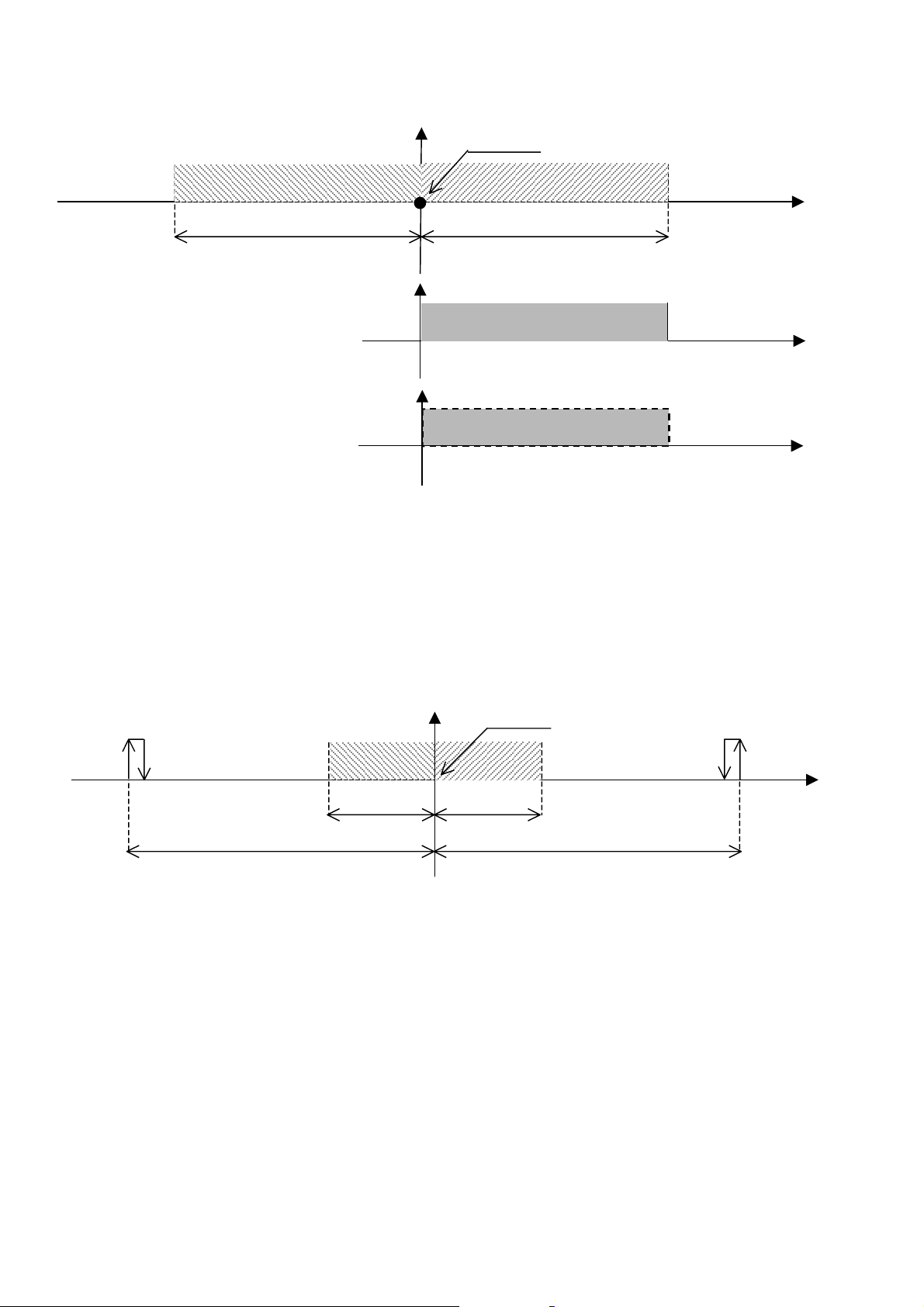
Standard air-conditioning units
y (%)
Q
y (%)
10.2 OTHER HUMIDITY FUNCTIONS
The high and low humidity alarms cause alarm screen signalling and have modifiable delay time.
In these close control units, the cold water coils provide for dehumidification. The humidification devices are the same as the direct expansion
close control units ones (On-Off contact, 0-10Volt modulating signal, built-in humidifier): for any information about their operation, refer to the
previous paragraph. The following diagrams show the dehumidification devices action. The percentage values indicate the modulating valves
opening range. Please note that the dehumidification cold water coils are enabled at 100%, not in modulating mode, in case of both threeposition and 0-10Volt valves.
100%
48.0 50.0 52.0
10.3 CLOSE CONTROL UNITS WITH WATER COILS
HUMIDIFICATION
2.0% 2.0%
Humidification proportional band
0%
0%
Humidity set
Dehumidification proportional band
VALVOLA ACQUA FREDDA 0-10V
-
50.0 52.0
VALVOLA AC
50.0 52.0
-
Humidity set
UA FREDDA 3 PUNTI
100%
100%
100%
Ambient
humidit
Ambient
humidity (%)
Ambient
humidity (%)
HUMIDIF.
10.0% 10.0%
Low humidity alarm High humidity alarm
2.0% 2.0%
Humid. band Dehum. band
DEHUMID.
Ambient
humidit
Carel Cod. +030221421 – Rel. 1.2 – April, 11, 2003
28

Standard air-conditioning units
(°C)
(°C)
p. (°C)
p. (°C)
(°C)
11.0 RECOVERY COIL
Recovery is an optional function: an additional cold coil using water coming from an external source (i.e., evaporation tower) is enabled if the
temperature of water running inside it is quite low. This allows saving on the system management costs. The coil is enabled by On-Off contact
or 0-10Volt modulating signal.
The following diagram shows the recovery coil enabling conditions: environment cooling request and recovery water temperature lower than
recovery set – recovery differential.
RECOVERY ENABLED
23.0 23.5 26.5
Dead z.
OFF ON OFF
Temperature set
0.5°C 3°C
Cold prop. band
10.0 12.0
Recovery set
Recovery differential
2°C
Ambient
temp.
Recovery
temp.
Recovery coil
state
11.1 RECOVERY WITHOUT COOLING DEVICES
As shown in the previous diagram, the recovery coil only is enabled, whereas the conventional cooling devices are not switched on; as it can be
noted in the following diagram, the recovery coil takes up the entire cold proportional band.
Temperature set
100%
19.5 22.5 23.0 23.5 26.5
HEATING
3°C 0.5°C 0.5°C 3°C
Warm proportional band
Dead z. Dead z.
Cold proportional band
100%
Ambient
tem
23.0 23.5 26.5
RECOVERY ON-OFF CONTACT
Ambient
tem
23.0 23.5 26.5
0-10V RECOVERY VALVE
100%
Ambient
temp.
Carel Cod. +030221421 – Rel. 1.2 – April, 11, 2003
29

Standard air-conditioning units
p. (°C)
(°C)
p. (°C)
(°C)
(°C)
p. (°C)
(°C)
11.2 RECOVERY WITH COOLING DEVICES ON CLOSE CONTR. UNITS WITH DIRECT EXPAN. COIL
With recovery coil enabled, the conventional cooling devices are switched on only if ambient temperature increases above a certain value;
adding the effects of recovery coil and devices together, temperature decreases, but before reaching the set point, the cooling devices are
switched off again. In this case, the cooling devices favour Recovery but do not substitute for it. The following diagram shows how the cooling
devices steps are offset compared to normal position to ensure energy saving.
HEAT.
22.5 23.0 23.5 26.5
0.5°C 0.5°C 3°C
Dead z. Dead z.
Temperature set
Cold proportional band
100%
Ambient
tem
23.0 23.5 24.6 24.9 26.5
OFF
23.0 23.5 24.6 24.9 25.6 26.5
OFF
23.0 23.5 24.6 24.9 25.1 25.6 26.1 26.5
OFF
RECOVERY COIL
-
RECOVERY COIL
-
RECOVERY COIL
-
ON
-
ON
-
-
COMPR. 1
ON
C.1 C. 1 C.2 C.1
c. c. c. c.
1 COMPRESSOR
COMPR. 2 /
Ambient
temp.
Ambient
tem
Ambient
temp.
11.3 RECOVERY WITH COOLING DEVICES ON CLOSE CONTROL UNITS WITH WATER COILS
The following diagram shows how the cold coil steps are offset compared to normal position to ensure energy saving.
Temperature set
HEAT.
0.5°C 0.5°C 3°C
Dead z. Dead z.
Cold proportional band
23.0 23.5 24.6 24.9 26.5
OFF
RECOVERY COIL
-
ON
-
0-10V MOD. WARM VALVE
23.0 23.5 24.6 24.9 26.5
OFF
RECOVERY COIL
-
-
ON
THREE-P. WARM VALVE
100%
Ambient
temp.
Ambient
tem
Ambient
temp.
Carel Cod. +030221421 – Rel. 1.2 – April, 11, 2003
30

Standard air-conditioning units
(°C)
(°C)
(°C)
p. (°C)
(°C)
(°C)
(°C)
12.0 OUTLET LIMIT
This function prevents too cold air from circulating in the environment, thus safeguarding health of any exposed person. A temperature probe
must be positioned on the air-conditioning unit outlet and parameters “Outlet set point” and “Outlet differential” shall be set. Such parameters
identify a limiting zone, as shown in the following diagram:
TOTAL
LIMITATION
100%
10.0 15.0
VARIABLE LIMITATION
5.0°C
Outlet differential
Outlet set
LIMITATION OFF
Outlet temp.
Temperature set
As shown in the diagram, if outlet temperature ranges between outlet set point and outlet differential, the cooling devices are limited only
partially; the more temperature decreases the more limitation increases.
As regards dehumidification limitation, the modulation zone is by-passed since dehumidification always needs the cooling devices maximum
capacity. In practice, the devices are switched off only if outlet temperature is lower than differential; the devices are then switched on again if
outlet temperature reaches the outlet set point, as shown in the following diagram:
TOTAL
LIMITATION
23.0 23.5 26.5
COMPRESSOR 1
23.0 23.5 25.0 26.5
COMP.1 C1 c. c. COMP.2 C2 c. c.
23.0 23.5 24.2 25.0 25.7 26.5
0-10V COLD WATER VALVE
0%
23.0 23.5 26.5
THREE-POINT COLD WATER VALVE
0%
23.0 23.5 26.5
ON
10.0 15.0
1 COMPRESSOR
COMPRESSOR 2 /
OUTLET LIMITATION
5.0°C
Outlet differential
100%
100%
Outlet set
Ambient
temp.
Ambient
tem
Ambient
temp.
Ambient
temp.
Ambient
temp.
LIMITATION OFF
Outlet temp.
Carel Cod. +030221421 – Rel. 1.2 – April, 11, 2003
31

Standard air-conditioning units
p
p
13.0 CONDENSER FANS
Condensing pressure control is available on ED type units, in which fans are managed based on condensing coil pressure and compressors state.
Fans are enabled by 0-10V modulating or digital outputs (on medium boards). Control is based on the condensation set point and differential, as
shown in the following diagram:
Condensation set
ON
OFF
ON
OFF
The following diagram shows fans operation with modulating outputs:
The maximum and minimum speeds of 0-10V outputs can be set; in case the set minimum speed is higher than 0V, the fan is operated at
minimum speed 1.0 bar below the condensation set point before switching off, as indicated in the diagram above.
13.1 SINGLE OR SEPARATE COILS
In case of single coil, only one output (on-off or modulating) is enabled. In case of units with at least one condensing probe and enabled on-off
outputs (medium boards), two on-off outputs may be enabled in sequence, dividing the differential by two.
In case of separated coils, two different outputs (on-off or modulating) are enabled, one per circuit.
13.2 NUMBER OF PROBES
Foreword: besides the values read by the probes, fans enabling always considers the compressors state.
In case of single probe and separated coils, fans enabling is based on the probe value for both circuits.
In case of two probes and single coil, fans enabling is based on the highest probes value.
In case of two probes and separated coils, fans enabling is based on the probe value of the relevant circuit.
In case no probe is present, fans are enabled simultaneously with the compressors; in case of single coil, fans are enabled when at least one
compressor is on; in case of separated coils, each compressor controls the fans of its own circuit.
13.3 PREVENT FUNCTION
High pressure alarm prevention with compressors stopped. Normally, the condensing fans turn on only if compressors are enabled, but in this
case they are forced so as to decrease pressure and try to prevent the high pressure alarm, which would cause unit shutdown. Pressure increase
with compressors stopped may be due to radiance on the coil. In case of 0-10V modulating fans, modulation is by-passed.
13.4 SPEED-UP FUNCTION
To overcome inertia at high-power modulating fans peak, they may be started at maximum speed for some seconds, then speed decreases to the
required value and modulation starts.
13.5 PRESSURE – TEMPERATURE CONVERSION
Both pressure and temperature probes can be selected. In case of pressure probes, branch I/O screens display the temperature value
corresponding to the pressure of each probe, based on the coolant type (to be selected in the Manufacturer branch).
14.0 16.0 18.0 20.0 23.5 24.5
2.0 bar 2.0 bar 1.0 bar
Condensation differential Prevent differential HP differential
100%
13.0 0% 14.0 16.0
2.0 bar
Condensation differential
Opening start point (100%)
Opening end point
Condensation
ressure (bar)
Compressor
state
Condensing fans
state
Condensation
ressure (bar)
(0%)
Carel Cod. +030221421 – Rel. 1.2 – April, 11, 2003
32

Standard air-conditioning units
p. (°C)
p
(°C)
14.0 TEMPERATURE SET POINT COMPENSATION
The temperature set point can be “compensated” automatically for comfort reasons; for example, think about a commercial concern in which
people frequently enter and go out: if internal temperature is 10°C lower than the external one, the thermal rush may annoy people and could be
prejudicial to their health. The maximum difference between internal and external temperatures should not exceed 6°C in order to obtain
optimum comfort. In this case, the compensation function increases the set point by 4°C, consequently increasing the ambient temperature; this
function prevents the difference between internal and external temperature from exceeding 6°C.
Compensation requires a temperature probe to be installed at the exterior. The function is managed based on the values of compensation set
point, differential and offset parameters, as shown in the following diagram:
Compensation set
25.0 28.0
Compensation proportional band
3°C
2°C
Compensation
offset
External
tem
25.0°C
23.0°C
Temperature set-
oint
15.0 COMPRESSORS
Compressors are managed in ON-OFF mode. Maximum 2 compressors can be present, each having capacity control. Therefore, the total amount
of compressors + capacity controls allows for 4 cold steps.
15.1 CAPACITY CONTROL
Their logic can be N.O. (relays normally open) or N.C. (relays normally closed). With respect to compressors, these controls are enabled with a
programmable delay time. The capacity controls are available for medium boards only. During dehumidification, capacity controls are started
simultaneously with the compressors to obtain the maximum cooling power.
15.2 ROTATION
Compressors rotation follows the F.I.F.O. (first in, first out) logic. The first compressor turned on is the first to turn off, the first compressor
turned off is the last to turn on. This logic allows comparing the compressors working hours and obtaining the same ageing.
15.3 TIMING
15.3.1 START MINIMUM TIME
It represents the compressors start minimum time (in seconds) after they have been enabled. If a stop request arises, compressors are disabled
only after the established time has elapsed.
It represents the compressors stop minimum time (in seconds) after they have been disabled. If a start request arises, compressors are enabled
only after the established time has elapsed.
It represents the minimum time interval (in seconds) between start of a device and the following one. This interval allows preventing
contemporary peaks, which would cause a high energy absorption.
It represents the minimum time interval (in seconds) between two starts of the same device. This parameter allows limiting the number of starts
per hour. If, for example, the maximum number of starts per hour allowed by the default values is 10, this limit can be respected by setting a
360-second time interval.
It represents the minimum time between compressor and capacity control start. This parameter is available only if capacity controls have been
selected.
15.3.2 STOP MINIMUM TIME
15.3.3 MINIMUM TIME BETWEEN DIFFERENT COMPRESSORS STARTS
15.3.4 MINIMUM TIME BETWEEN COMPRESSOR STARTS
15.3.5 CAPACITY CONTROLS START MINIMUM TIME
Carel Cod. +030221421 – Rel. 1.2 – April, 11, 2003
33

Standard air-conditioning units
15.4 COMPRESSOR ALARMS
Compressors alarms are distributed in two digital inputs, with an exception for the two-compressor ED configuration on small boards, in which
the alarms are compacted in a single digital input.
In case two digital inputs are present, the alarms mean Thermal alarm / High and Low pressure alarm.
In case a single digital input is present, the alarm means General alarm.
If any alarm input shall not be used, the 24Vac supply needs to be energised.
As for electrical connections of alarm digital inputs, refer to the pCO1 – pCO2 boards technical manual.
15.4.1 HIGH PRESSURE – THERMAL ALARM
Immediate alarm originated by external pressure switch or compressor overload; the digital input switches from closed to open and compressor
is immediately stopped. To start the compressor again, the user has to rearm the alarm manually by pushing the terminal Alarm button, provided
that the pressure switch or compressor overload have rearmed energising the digital input. After the compressor has turned off, timing is
enabled; for this reason, after alarm rearming, the compressor could not immediately turn on again.
15.4.2 LOW PRESSURE ALARM
Delayed alarm originated by an external pressure switch. When opening, the digital input enables two timers; if, when the timers delay time
(programmable by screen) elapses, the contact is open, the compressor turns off and the alarm goes off. On the contrary, if the contact closes
before delay time elapses, the alarm does not go off and timers reset. Timers are: running compressor delay time and compressor start delay
time. Running delay is always counted, whereas compressor start delay is counted only if the input opens immediately after compressor start
and allows for fluid stabilisation. The two timers are counted in sequence.
To start the compressor again, the user has to rearm the alarm manually by pushing the terminal Alarm button, provided that the pressure switch
has rearmed energising the digital input. After the compressor has turned off, timing is enabled; for this reason, after alarm rearming, the
compressor could not immediately turn on again.
15.4.3 GENERIC ALARM
Alarm including all compressor safety devices in a single digital input, used on two-compressor small boards. This alarm goes off immediately
when opening the digital input and locks the compressor. To start the compressor again, the user has to rearm the alarm manually by pushing the
terminal Alarm button, provided that the digital input has been energised. After the compressor has turned off, timing is enabled; for this reason,
after alarm rearming, the compressor could not immediately turn on again.
16.0 HEATERS
The heaters are managed as simple ON-OFF loads. Normally up to 2 heaters with the same power can be managed, connected to the 2 outputs.
“Binary management” allows the use of three heating steps with just two outputs. Consequently, there are two possible options:
management of 2 loads with different power values;
management of 3 loads. To use this system, a recognizer is required (NOT supplied), which, connected to the outputs, reads the logic and
activates the loads.
The outputs behave as follows:
CODE 2 DIFFERENT LOADS 3 LOADS
STEP 1 Relay 1=On Relay 2=Off 10 Heat.1=On / Heat.2=Off Heat.1=On / Heat.2=Off /
Heat.3=Off
STEP 2 Relay 1=Off Relay 2=On 01 Heat.1=Off / Heat.2=On Heat.1=On / Heat.2=On /
Heat.3=Off
STEP 3 Relay 1=On Relay 2=On 11 Heat.1=On / Heat.2=On Heat.1=On / Heat.2=On /
Heat.3=On
The outputs are activated with a slight delay from one to the other, to avoid simultaneous peaks.
16.1 HEATER ALARMS
Each heater is provided with a digital input to be connected with a compressor overload or differential for signalling any failure.
If any input shall not be used, the 24Vac supply needs to be energised.
Immediate alarm originated when the digital input switches from closed to open; the heater is immediately disabled. To enable the heaters again,
the user has to rearm the alarm manually by pushing the terminal Alarm button, provided that the compressor overload or the differential have
rearmed energising the digital input.
Carel Cod. +030221421 – Rel. 1.2 – April, 11, 2003
34

Standard air-conditioning units
17.0 MODULATING VALVES
17.1 THREE-POSITION VALVES
Valves with three electrical contacts (besides supply): shared, opening and closing. The two relays of pCO1-pCO2 boards (opening – closing
relays) must be connected to these contacts.
Based on the relays enabling time, the valves opening range varies from 0% to 100% taking an opening/closing time defined as “running time”
(time taken to open or close completely; it is a valves rating). The relays must never be enabled simultaneously, thus the valve open, close or
keep still.
The valves opening range is calculated based on the proportion between temperature differential and running time. When ambient temperature
corresponds to the set point, the valves keep closed; the more temperature is offset compared to the set point the more the valves are opened,
until they open completely when temperature is equal or higher than set point + / - differential.
During operation, the valves are frequently subject to partial opening and closing; the program can recognise the valves opening range at any
time by adding up and subtracting all partial times executed from board start-up.
17.1.1 REALIGNMENT
As there is no feedback to define precisely the valves opening range, the program cannot easily manage the three-position valves. A slight
difference between the time calculated by the program and the relays enabling time or a mechanical friction preventing the valves from moving
freely may originate discrepancy between the valves actual opening range and the range calculated by the program. To obviate this problem, the
following precautions are provided for:
• whenever temperature control requires a valve complete opening or closing, the program increases the opening or closing relay
enabling time by 25% to ensure complete opening/closing.
• whenever the board is started, the valves are completely closed during the running time; only after time has elapsed, the valves start
modulating their opening range based on the control request.
17.2 0-10Volt VALVES
These valves use a 0-10Volt modulating signal coming from the pCO1-pCO2 to modify their opening range from 0% to 100%.
The 0-10Volt electric signal is directly proportional to the temperature proportional band. Unlike the three-position valves, these valves do not
require adjustment since their opening range is directly proportional to the analogue output value.
18.0 OUTLET FAN
With unit enabled, the outlet fan keeps switched on. It can be managed with On–Off or modulating output. The fan is provided with a thermal
alarm and an air flow controller alarm, which lock the unit setting it to OFF state; thermal alarm requires manual rearm, whereas air flow
controller alarm is rearmed automatically. Description of modulating management:
100%
During dehumidification, speed is automatically decreased to 5.0V (50%) default value, modifiable if required. The minimum and maximum
speeds default values correspond to 5.0V and 10.0V, modifiable if required.
19.5 22.5 23.0 23.5 26.5
100%
HEATING
3°C 0.5°C 0.5°C 3°C
Warm proportional band
Min. speed (5.0V)
Max. speed (10.0V)
Temperature set
Cold proportional band
COOLING
100%
100%
Fan speed
19.0 MANUAL DEVICE MANAGEMENT
The devices connected to outputs can be enabled manually without using timing, compressors rotation and independently from control and
probes values. In manual mode, the only available support is the management of the alarms safeguarding devices safety and soundness. The
analogue outputs enabling allows forcing a value between 0V and 10V.
The manual procedure can be enabled by button only if the unit is in OFF mode and is automatically stopped within 30 minutes after enabling
the last device or disabling all devices manually.
During devices manual management, the air-conditioning unit cannot be turned on. This operative mode is identified by message “MANUAL
PROCEDURE” shown on the last display row, on the Menu main screen. The enabling parameters are displayed in the Maintenance screens
branch under Password.
Carel Cod. +030221421 – Rel. 1.2 – April, 11, 2003
35

Standard air-conditioning units
20.0 ALARM DATA LOGGING
Alarms data logging allows storing the air-conditioning unit working state whenever an alarm goes off or under particular conditions. Any
storing operation becomes an event, which can be displayed as any other event available in the memory. As it functions as a device for “taking
photographs” of the system whenever any alarm goes off, data logging is extremely useful for suggesting possible causes and solving system
malfunctions and failures. The program is provided with a MAIN and a DEVELOPED data logging.
20.1 MAIN LOG (pCO1 – pCO2)
Events can be stored thanks to the pCO1-pCO2 boards very large buffer memory. The MAIN data logging can be enabled by parameter; if the
clock card (optional on pCO1, integrated on pCO2) is not available, neither the MAIN data logging is available. No additional optional card is
required.
The maximum number of storable events is 100; after the last space available in the memory (alarm no. 100) is used, next alarm will be
overwritten on the first alarm stored (001), which will be automatically deleted. This procedure applies to all following events. The user cannot
delete the stored events except at the default values installation. The MAIN data logging screen can be accessed by pushing button ALARM
when screen E4 is displayed and can be left by pushing button Menu (Esc if the built-in terminal is being used). The screen is displayed as
follows:
Whenever an alarm goes off, the following air-conditioning unit data are stored for each alarm:
• alarm description
• time
• date
• event chronological number (0-100)
The event chronological number, displayed in the upper right corner, indicates the event “stay time” compared to the 100 available memory
spaces. Alarm no. 001 represents the first alarm gone off after MAIN data logging enabling.
Moving the cursor on the chronological number and using the arrow buttons, the alarms “history” can be scrolled from 1 to 100.
In position 001 and pushing the down arrow, the alarms cannot be scrolled.
If, for example, 15 alarms have been stored and the cursor is in position 015, pushing the up arrow, the alarms cannot be scrolled.
20.2 ADVANCED LOG (pCO2)
The events are saved in the 1MB or 2MB memory expansion, available on the pCO2 board. The advantages and characteristics of this log are as
follows:
• Log by event: a typical log by event is the alarm log. When an alarm is activated, the event is saved together with other significant
values (temperature, humidity, pressure, set point, etc.).
• Log by time: a typical log by time is the temperature/humidity log. The temperature and humidity values are saved at regular intervals.
• Log of logs: a typical log of logs involves the saving of the last alarms/temperature/humidity values recorded before a serious alarm.
Unlike the data saved for the log by event and log by time, this data is not overwritten when the memory is full.
• Possibility to choose the values to be saved and the saving options at any time. The “WinLOAD” program can be used to define, using
a practical “Wizard”, the values to be saved and the options. WinLOAD does not require the application program “files”, as it is able
to directly receive all the information required from the program installed on the pCO1 – pCO2.
• 1MB dedicated FLASH memory. The system saves the data in the 1MB FLASH memory in the memory expansion (code
PCO200MEM0). For example, 1MB of memory is able to store 5000 alarm events with 5 values per alarm, and record 2 values, such
as temperature and humidity, for 6 months, saved every 5 minutes.
• Possibility to define up to 7 different log configurations. Typically, each controller will have an alarm log, a log of the control values
(temperature/humidity/pressure) and some “logs of logs”.
• Possibility to display the data saved on the terminal LCD (external or built-in), or on a PC.
• “Black box” function. The memory expansion that contains the logs can be removed from the pCO² on the unit controlled and inserted
in another pCO² to display the data saved. The latter pCO² does not need to have the same application program as the original.
• Reliability of the da ta saved. The data are saved in FLASH me mory, which does not require batteries that risk being discharged. If
following a software update the previously saved data are incompatible with the new software, all the data will be deleted (following
confirmation).
20.2.1 CONFIGURATION USING “WINLOAD”
The Advanced Log function, including all the options described above, is configured using the “On line help” feature in the WINLOAD32
program, the same used to upload the program software to the pC01 and pCO2 boards.
HISTORY_ALARMS
+--------------------+
¦Alarms historic H025¦
¦ ¦
¦Resistor 1 overload ¦
¦12:34 01/08/01¦
+--------------------+
Carel Cod. +030221421 – Rel. 1.2 – April, 11, 2003
36

Standard air-conditioning units
21.0 SUPERVISION
pCO1 and pCO2 can be connected with a local or remote supervisory PC, a GSM or traditional modem and the most spread BMS (Modbus,
Bacnet, Lonworks). To be used, the listed functions require the installation of optional cards (Rs485, Rs232, LON) or Gateways (devices able to
interpret different communication protocols).
21.1 CAREL SUPERVISOR
The local connection between pCO1 – pCO2 board and a supervisory PC requires the insertion of the Rs485 additional card (pCO2:
PCO2004850; pCO1: PCO1004850) into the “Serial card” port. From the additional card, connect to the Rs485 serial line up to the
Rs485/Rs232 converter supplied by Carel (PC485KIT00) for connection with the PC.
In case of remote supervisor with supervisory PC connected with the telephone line, simply install the Rs232 optional card (pCO2:
PCO200MDM0; pCO1: PCO100MDM0) and connect it to a traditional modem (not GSM). The program allows managing the modem and
setting the phone numbers to be called. As for connections, refer to the instruction sheet.
21.2 BMS
The connection with the BMS supervisory systems is executed in different ways.
Lonworks: insert the additional card into the “Serial card” port (pCO2: PCO20LFTTL / PCO20L485L; pCO1: PCO10LFTTL / PCO10L485L)
and connect as prescribed in the instruction sheet. Enable LON function on the LCD terminal.
Modbus: insert the Rs485 additional card; the card only is required since the program manages this protocol by itself.
Bacnet: insert the Rs485 additional card and connect it with Carel’s gateway code GATEWAYBN0 by Rs485 line.
Owners’ BMS: Carel has developed many other Gateways for interfacing with less spread BMS, i.e. OTE.
21.3 GSM PROTOCOL
By selecting the GSM protocol, SMS (text) messages can be sent to and from GSM phones, using a GSM modem. The pCO1 or pCO2 sends a
message to the phone in the event of alarms, and can receive messages from the telephone at any time; the user can in fact use a GSM phone to
modify some of the unit's parameters, as listed below:
Parameter Unit Add. 1 Unit Add. 2 Unit Add. 3 Unit Add. 4 Unit Add. 5 Unit Add. 6 Unit Add. 7 Unit Add. 8
Temperature set point analogue 1 analogue 10 analogue 19 analogue 28 analogue 37 analogue 46 analogue 55 analogue 64
Humidity set point analogue 2 analogue 11 analogue 20 analogue 29 analogue 38 analogue 47 analogue 56 analogue 65
Recovery set point analogue 3 analogue 12 analogue 21 analogue 30 analogue 39 analogue 48 analogue 57 analogue 66
Compensation set point analogue 4 analogue 13 analogue 22 analogue 31 analogue 40 analogue 49 analogue 58 analogue 67
Low temperature ala r m
threshold offset
High temperature alarm
threshold offset
Low humidity alarm
threshold offset
High h u midi t y t h r e shol d offs e t analogue 8 analogue 17 analogue 26 analogue 35 analogue 44 analogue 53 analogue 62 analogue 71
Outlet air limit set point analogue 9 analogue 18 analogue 27 analogue 36 analogue 45 analogue 54 analogue 63 analogue 72
Unit On-off digital 1 digital 2 digital 3 digital 4 digital 5 digital 6 digital 7 digital 8
For details on the syntax of the SMS messages sent to the pCO* and on the use of the above table, refer to the manual: GSM modem protocol for
pCO2 (code+030220330).
N.B. When the GSM protocol is active, the remote supervisor cannot call the pCO1 or pCO2 board.
21.4 VARIABLE DATABASE
A specific communication database is featured that includes all the more important program variables, from the values read by the probes to the
parameters set on the screens. The following table describes the database, divided into digital , integer and analogue variables, indicating for
each its description, address and type, that is, read-only (R) or modifiable from the supervisor (R/W).
21.4.1 DIGITAL VARIABLES
DESCRIPTION SCR ADD TYPE DESCRIPTION SCR. ADD. TYPE
Digital input number 1 I3 1 R Humid. operating hour threshold alarm A36 63 R
Digital input number 2 I3 2 R Thermal cutout and high pressure alarm,
Digital input number 3 I3 3 R Condens. 1 fan thermal cutout alarm A38 65 R
Digital input number 4 I3 4 R Condens. 2 fan thermal cutout alarm A39 66 R
Digital input number 5 I3 5 R Water flow alarm A40 67 R
Digital input number 6 I3 6 R Enable compressors/cooling coil together
Digital input number 7 I3 7 R Enable outside temperature probe Cl 70 R/W
Digital input number 8 I3 8 R Enable pressure probe 1 Ci 71 R/W
Digital input number 9 I3 9 R Enable pressure probe 2 Cj 72 R/W
Digital input number 10 I3 10 R Enable humidity probe Ch 73 R/W
Humidifier water level contact I3 11 R Enable outlet probe Ck 74 R/W
Digital input number 12 I3 12 R Enable condenser 1 temp. probe Cm 75 R/W
Digital input number 13 I3 13 R Enable condenser 2 temp. probe Cm 76 R/W
Digital input number 14 I3 14 R Enable recovery probe Cl 77 R/W
Digital output number 1 I7 15 R Modulating output 1 configuration
Digital output number 2 I7 16 R Type of unit (0=ED; 1=CW) C1 79 R/W
Digital output number 3 I7 17 R Modulating output 2 configuration
Digital output number 4 I7 18 R Digital input 1 configuration
Digital output number 5 I7 19 R Digital input 12 configuration C5 82 R/W
analogue 5 analogue 14 analogue 23 analogue 32 analogue 41 analogue 50 analogue 59 analogue 68
analogue 6 analogue 15 analogue 24 analogue 33 analogue 42 analogue 51 analogue 60 analogue 69
analogue 7 analogue 16 analogue 25 analogue 34 analogue 43 analogue 52 analogue 61 analogue 70
A37 64 R
comp. 2
G0 69 R/W
with recovery coil
Ca 78 R/W
(0=rec. valve; 1=modulating fan)
Cb 80 R/W
(0=recovery valve; 1=humidifier)
C6 81 R/W
(0=fire/smoke; 1=flood)
Carel Cod. +030221421 – Rel. 1.2 – April, 11, 2003
37

Standard air-conditioning units
DESCRIPTION SCR ADD TYPE DESCRIPTION SCR. ADD. TYPE
(0=fire/smoke; 1=flood)
Digital output number 6 I7 20 R Enable modulating outlet fan Cc 83 R/W
Digital output number 7 I7 21 R Heating mode
Digital output number 8 I7 22 R Type of valve on cooling coil (0=0-10V;
Digital output number 9 I7 23 R Type of valve on heating coil (0=0-10V;
Digital output number 10 I7 24 R Enable modulating 0-10V humidifier
Digital output number 11 I7 25 R Type of coil on main unit CW (0=single;
Digital output number 12 I7 26 R Type of condenser (0=single coil;
Digital output number 13 I7 27 R Select type of fans (0=inverter; 1=steps) Cd 90 R/W
Generic alarm compressor 1 A01 28 R Enable condenser function Cd 91 R/W
Generic alarm compressor 2 A02 29 R Enable high press. Prevent function Gh-Gi 92 R/W
Low pressure alarm compressor 1 A03 30 R Enable outlet limit function Pa 93 R/W
Low pressure alarm compressor 2 A04 31 R Enable compensation function P7 94 R/W
Air flow alarm A05 32 R Enable cooling coil for dehumidif. Cf 95 R/W
Fan thermal cutout alarm A06 33 R Enable recovery coil Cc 96 R/W
Thermal cutout alarm heater 1 A07 34 R Dehumidif contact logic (0=NO; 1=NC) Cf 97 R/W
Thermal cutout alarm heater 2 A08 35 R Enable FIFO compressor rotation G1 98 R/W
Fire / smoke alarm A09 36 R Enable compressor capacity-control steps C2 99 R/W
Dirty filter alarm A10 37 R Cap. control contact logic (0=NO; 1=NC) G1 100 R/W
High ambient temperature alarm A11 38 R Type of temperature control (0=P; 1=P+I) G1 101 R/W
Low ambient temperature alarm A12 39 R Enable built-in humidifier Cf 102 R/W
High ambient humidity alarm A13 40 R
Low ambient humidity alarm A14 41 R
Op. hour threshold alarm, compressor 1 A15 42 R Enable Carel Master Control Gj 105 R/W
Op. hour threshold alarm, compressor 2 A16 43 R Enable Force units in pLAN Gm 106 R/W
Op. hour threshold alarm, fan A17 44 R Enable On-Off time bands K2 107 R/W
Room temperature probe faulty alarm A18 45 R Enable temperature time bands K2 108 R/W
Recovery temperature probe faulty alarm A19 46 R Enable humidity time bands K2 109 R/W
Outside temperature probe faulty alarm A20 47 R Enable unit off from button P5 110 R/W
Outlet temperature probe faulty alarm A21 48 R Enable remote On-Off dig. input P5 111 R/W
Room humidity probe faulty alarm A22 49 R Unit On-Off from supervisor --- 112 R/W
Pressure probe 1 faulty alarm A23 50 R Digital output 7 configuration
Pressure probe 2 faulty alarm A24 51 R Select temperature unit of measure C0 114 R/W
Cond. temp. probe 1 faulty alarm A25 52 R Enable clock card (pCO1) C0 115 R/W
Cond. temp. probe 2 faulty alarm A26 53 R Enable printer C0 116 R/W
High current in the humidifier alarm A27 54 R Confirm hour setting K0 117 R/W
No water in humidifier alarm A28 55 R Confirm minute setting K0 118 R/W
No current in humidifier alarm A29 56 R Confirm day setting K0 119 R/W
Clock card fault alarm A30 57 R Confirm month setting K0 120 R/W
High pressure alarm circuit 1 A31 58 R Confirm year setting K0 121 R/W
High pressure alarm circuit 2 A32 59 R Reset alarms from supervisor --- 123 R/W
Flood alarm A33 60 R
Auxiliary alarm A34 61 R
Thermal cutout and high pressure alarm,
comp. 1
A35 62 R
(0=heaters; 1=hot coil)
1=3pos)
1=3pos)
output
1=double)
1=separate coils)
(0=recovery valve; 1=minor alarms)
C2-C3 84 R/W
C3 85 R/W
C2-C3 86 R/W
Ca 87 R/W
C3 88 R/W
Cd 89 R/W
C7 113 R/W
21.4.2 ANALOGUE VARIABLES
DESCRIPTION SCR ADD. TYPE DESCRIPTION SCR. ADD. TYPE
Room humidity probe reading 1 W Condensing (pressure) differential Ge 43 R/W
Pressure probe 1 reading 2 W Condensing (temp.) differential Gf 44 R/W
Pressure probe 2 reading 3 W Max condenser fan speed Gg 45 R/W
Room temperature probe reading 4 W Min condenser fan speed Gg 46 R/W
Air outlet temperature probe reading 5 W Condensing (pressure) set point Ge 47 R/W
Outside temperature probe reading 6 W Condensing (temperature) set point Gf 48 R/W
Cond. 1 temperature probe reading 7 W High ambient temperature alarm offset P8 53 R/W
Cond. 2 temperature probe reading 8 W Low ambient temperature alarm offset P8 54 R/W
Water recovery temperature probe reading 9 W High ambient humidity alarm offset P9 55 R/W
Temperature set point S1 10 R/W Low ambient humidity alarm offset P9 56 R/W
Minimum temperature set point limit P1 11 R/W End point to open modulating humidifier
Maximum temperature set point limit P1 12 R/W Starting point to open modulating
Humidity set point S1 13 R/W Maximum humidifier production Cg 59 R/W
Minimum humidity set point limit P2 14 R/W Maximum outlet fan speed G7 60 R/W
Maximum humidity set point limit P2 15 R/W Minimum outlet fan speed G7 61 R/W
Temperature time band set point Z1 K6 16 R/W Maximum value humidity probe Ch 62 R/W
Temperature time band set point Z2 K6 17 R/W Minimum value humidity probe Ch 63 R/W
Temperature time band set point Z3 K7 18 R/W Maximum value pressure probe 1 Ci 64 R/W
Carel Cod. +030221421 – Rel. 1.2 – April, 11, 2003
output
humidifier output
38
G8 57 R/W
G8 58 R/W

Standard air-conditioning units
DESCRIPTION SCR ADD. TYPE DESCRIPTION SCR. ADD. TYPE
Temperature time band set point Z4 K7 19 R/W Minimum value pressure probe 1 Ci 65 R/W
Humidity time band set point Z1 K8 20 R/W Maximum value pressure probe 2 Cj 66 R/W
Humidity time band set point Z2 K8 21 R/W Minimum value pressure probe 2 Cj 67 R/W
Humidity time band set point Z3 K9 22 R/W Restart dehumidification temp. offset G9 68 R/W
Humidity time band set point Z4 K9 23 R/W Prevent (pressure) differential Gh 69 R/W
Temperature dead zone P3 24 R/W Prevent (temperature) differential Gi 70 R/W
Proportional band in Cooling P3 25 R/W Prevent (pressure) set point Gh 71 R/W
Proportional band in Heating P3 26 R/W Prevent (temperature) set point Gi 72 R/W
Proportional band in Humidification P4 27 R/W Water recovery set point temperature P6 73 R/W
Proportional band in Dehumidification P4 28 R/W High pressure alarm set point Gd 74 R/W
Maximum compensation set temp. offset P7 29 R/W Air outlet set point Pa 75 R/W
Outside temperature probe calibration Ea 30 R/W Outside air set point for compensation P7 76 R/W
Condens. 1 pressure probe calibration E9 31 R/W Outlet fan speed in dehumid. G7 77 R/W
Condens. 2 pressure probe calibration E9 32 R/W Current superheating value driver 1 Ik 78 R
Humidity probe calibration E9 33 R/W Evaporation temperature driver 1 Ik 79 R
Room temperature probe calibration Ea 34 R/W Suction temperature driver 1 Ik 80 R
Outlet temperature probe calibration Ea 35 R/W Evaporation pressure driver 1 Il 81 R
Condens.1 temperature probe calibration Eb 36 R/W Condensing temperature driver 1 Im 82 R
Condens.2 temperature probe calibration Eb 37 R/W Current superheating value driver 2 Ip 83 R
Recovery temperature probe calibration Eb 38 R/W Evaporation temperature driver 2 Ip 84 R
Stop dehumidification temp. differential G9 39 R/W Suction temperature driver 2 Ip 85 R
Air outlet differential Pa 40 R/W Evaporation pressure driver 2 Iq 86 R
Outside air differential for compensation P7 41 R/W Condensing temperature driver 2 Ir 87 R
High pressure alarm differential Gd 42 R/W
21.4.3 INTEGER VARIABLES
DESCRIPTION SCR ADD. TYPE DESCRIPTION SCR ADD. TYPE
Analogue output 1 1 R Start minutes On-Off time band F1-1 K3 59 R/W
Analogue output 2 2 R End hour On-Off time band F1-1 K3 60 R/W
Analogue output 3 3 R End minutes On-Off time band F1-1 K3 61 R/W
Analogue output 4 4 R Start hour On-Off time band F1-2 K3 62 R/W
Current hour 5 R Start minutes On-Off time band F1-2 K3 63 R/W
Current minutes 6 R End hour On-Off time band F1-2 K3 64 R/W
Day 7 R End minutes On-Off time band F1-2 K3 65 R/W
Month 8 R Start hour On-Off time band F2 K3 66 R/W
Year 9 R Start minutes On-Off time band F2 K3 67 R/W
Weekday 10 R End hour On-Off time band F2 K3 68 R/W
Hour setting K0 14 R/W End minutes On-Off time band F2 K3 69 R/W
Minute setting K0 15 R/W Start hour temperature time band Z1 K6 70 R/W
Day setting K0 16 R/W Start minutes temperature time band Z1 K6 71 R/W
Month setting K0 17 R/W Start hour temperature time band Z2 K6 72 R/W
Year setting K0 18 R/W Start minutes temperature time band Z2 K6 73 R/W
Number of compressors C2 20 R/W Start hour temperature time band Z3 K7 74 R/W
Number of compressors for dehumidify Cf 21 R/W Start minutes temperature time band Z3 K7 75 R/W
Select number of On-Off fans Cd 22 R/W Start hour temperature time band Z4 K7 76 R/W
Humber of heaters
Probe 2 input configuration (0=cond. 1
press.; 1=cond.1 temp.; 2=outlet temp.)
Probe 3 input configuration (0= cond.2
press.; 1=cond.2 temp.; 2=recovery temp.)
Digital input 5 configuration (0=flood;
1=filters; 2=fire/smoke)
Type of signal from the humidity probe
(2=0-1V; 3=0-10V; 4=current)
Type of signal pressure probe 1 (2=0-1V;
3=0-10V; 4=current)
Type of signal pressure probe 2 (2=0-1V;
3=0-10V; 4=current)
Type of signal condens. 1 T probe
(0=NTC; 1=PT1000; 2=0-1V; 3=0-10V;
4=current)
Type of signal condens. 2 T probe
(0=NTC; 1=PT1000; 2=0-1V; 3=0-10V;
4=current)
Type of signal from the temperature probe
external (0=NTC; 1=PT1000)
Type of signal from recovery temperature
probe (0=NTC; 1=PT1000)
Type of signal from room temperature
probe (0=NTC; 1=PT1000)
Type of signal from outlet temperature
probe (0=NTC; 1=PT1000)
Select refrigerant (0=no; 1=R22; 2=134a;
3=404a; 4=407C; 5=410A)
Air flow switch alarm delay T4 37 R/W Select On-Off time bands Saturday
Carel Cod. +030221421 – Rel. 1.2 – April, 11, 2003
C2-C3
23 R/W Start minutes temperature time band Z4 K7 77 R/W
C8 24 R/W Start hour humidity time band Z1 K8 78 R/W
C9 25 R/W Start minutes humidity time band Z1 K8 79 R/W
C4 26 R/W Start hour humidity time band Z2 K8 80 R/W
Ch 27 R/W Start minutes humidity time band Z2 K8 81 R/W
Ci 28 R/W Start hour humidity time band Z3 K9 82 R/W
Cj 29 R/W Start minutes hum idity time band Z3 K9 83 R/W
Cm 30 R/W Start hour humidity time band Z4 K9 84 R/W
Cm 31 R/W Start minutes humidity time band Z4 K9 85 R/W
Cl 32 R/W Select On-Off time bands Monday (0=F1;
1=F2; 2=F3; 3=F4)
Cl 33 R/W Select On-Off time bands Tuesday
(0=F1; 1=F2; 2=F3; 3=F4)
Ck 34 R/W Select On-Off time bands Wednesday
(0=F1; 1=F2; 2=F3; 3=F4)
Ck 35 Select On-Off time bands Thursday
(0=F1; 1=F2; 2=F3; 3=F4)
C1 36 R/W Select On-Off time bands Friday (0=F1;
1=F2; 2=F3; 3=F4)
(0=F1; 1=F2; 2=F3; 3=F4)
K5 86 R/W
K5 87 R/W
K5 88 R/W
K5 89 R/W
K5 90 R/W
K5 91 R/W
39

Standard air-conditioning units
DESCRIPTION SCR ADD. TYPE DESCRIPTION SCR ADD. TYPE
Outlet fan off delay T0 38 R/W Select On-Off time bands Sunday (0=F1;
Outlet fan start delay T0 39 R/W Cond. fan Speed-up time Ge-Gf 93 R/W
Compressor 1 operating hours threshold E8 94 R/W
Delay in activating minor alarm relay no.7 T3 40 R/W Compressor 2 operating hours threshold E8 95 R/W
Delay in activating serious alarm relay
no.8
Water flow switch alarm delay T4 42 R/W Fan operating hour threshold E8 97 R/W
Delay between starts of different
compressors
Heater start delay T8 44 R/W Forcing delay for high ambient temp. Gm 99 R/W
Low pressure alarm delay T2 45 R/W Forcing delay for low ambient temp. Gm 100 R/W
Integration time for P+I control T1 46 R/W Interval in days for automatic rotation Gl 101 R/W
Minimum compressor off time T5 47 R/W Hour automatic rotation Gl 102 R/W
Minimum compressor on time T5 48 R/W Minutes automatic rotation Gl 103 R/W
High ambient temperature differential to
force units in network
Delay between compressor starts T6 49 R/W Automatic rotation interval for units in
Low ambient temperature differential to
force units in network
Cap. control activation delay T7 50 R/W pLAN connection class board 2 (0=not
High ambient temperature offset to force
units in network
3 position valve travel time T1 51 R/W pLAN connection class board 4 (0=not
Low ambient temperature offset to force
units in network
High-low temperature-humidity alarm
delay
High conductivity pre-alarm threshold Gb 53 R/W pLAN connection class board 7 (0=not
High conductivity alarm delay Gb 54 R/W pLAN connection class board 8 (0=not
Type of humidifier Cg 55 R/W Valve position driver 1 Ij 115 R
Start hour On-Off time band F1-1 K3 58 R/W Valve position driver 2 Io 116 R
T3 41 R/W Humidifier operating hour threshold E8 96 R/W
T6 43 R/W Rotation mode for units in pLAN
Go 49 R/W Number of units in Standby mode Gk 105 R/W
Gn 50 R/W pLAN connection class board 1 (0=not
Go 51 R/W pLAN connection class board 3 (0=not
Gn 52 R/W pLAN connection class board 5 (0=not
T2 52 R/W pLAN connection class board 6 (0=not
1=F2; 2=F3; 3=F4)
network
pLAN
present; 1=present/no rot.;
2=present/rotation)
present; 1=present/no rot.;
2=present/rotation)
present; 1=present/no rot.;
2=present/rotation)
present; 1=present/no rot.;
2=present/rotation)
present; 1=present/no rot.;
2=present/rotation)
present; 1=present/no rot.;
2=present/rotation)
present; 1=present/no rot.;
2=present/rotation)
present; 1=present/no rot.;
2=present/rotation)
K5 92 R/W
Gk 98 R/W
Gk 106 R/W
Cn 107 R/W
Cn 108 R/W
Cn 109 R/W
Co 110 R/W
Co 111 R/W
Co 112 R/W
Cp 113 R/W
Cp 114 R/W
22.0 EXAMPLES OF INSTALLATION
The connection of pCO1 - pCO2 boards in pLAN network allows for the following functions:
1. balancing air-conditioning units working hours by spare units (in stand-by
2. spare units start-up in case other units stop due to serious alarms or black-out
3. spare units start-up to compensate for the excessive thermal load
4. controlling up to 8 air-conditioning units by a single external LCD terminal
5. operation of all air-conditioning units according to Master air-conditioning unit probes to adjust units operation
6. managing alarms printing and probes values by shared external terminal.
Connection in pLAN network allows configuring a wide range of systems. The following list includes the main system types to be possibly
created, in order of complexity, and provides suggestions for executing connections:
1. one or more independent air-conditioning units (board(s) with pLAN address 1 + external terminal(s), if any, with pLAN address 25);
2. two or more air-conditioning units and one external terminal (boards with pLAN addresses 1-8 connected with Rs485 via J11,
terminal with pLAN address 32 connected with one of the boards); this connection allows for the functions listed in the previous
paragraph;
3. two or more air-conditioning units in pLAN network, each provided with private display (boards with pLAN addresses 1-8 connected
with Rs485 via J11, terminals with pLAN addresses 25-32 connected with the relevant board); this connection allows for the functions
listed in the previous paragraph.
Networks in which boards are connected with the pLAN allow selecting the units involved in the Rotation functions, thus obtaining a mixed
network with interacting and independent units.
pLAN connection among the boards allows using a shared external terminal (add. 32) in addition to the boards private displays; this solution is
adopted where private displays are assembled on the air-conditioning units and the shared terminal is installed inside a room.
IMPORTANT: if only one board is being used, it must have pLAN address 1; no pLAN electric connection is required and the external
terminal, if any, must have pLAN address 25.
mode) rotation
Carel Cod. +030221421 – Rel. 1.2 – April, 11, 2003
40

Standard air-conditioning units
p. (°C)
22.1 SHARED EXTERNAL TERMINAL
The Menu main screen shows the pLAN address of the displayed board in the upper right corner;
in private displays, it is a fixed number corresponding to the pLAN address of the board they are
connected with (1-8).
Terminal no. 32 allows selecting the board to be displayed by pushing button Info; whenever a
button is pressed, the address displayed in the upper right corner increases by 1 and the display
shows the parameters of the board selected among the connected ones.
In case of a board alarm, the shared terminal automatically connects with it to display the alarm.
The shared terminal can be connected to any network board; in case of boards equipped with
built-in terminal, the shared terminal must be connected to connector J10 by a telephone cable; in
case of boards equipped with private external display, the shunt code TCONNJ6000, shown in
the following figure, is required (private=Term n; shared=Term n+1):
The shared terminal only allows printing all boards alarms and parameters.
22.2 AUTOMATIC START AND STAND-BY UNITS
The boards connected with pLAN network may be managed directly by the program under
“critical situations”, that is in case of failure (alarms, black-out…) or due to “Rotation” and
“Forcing” functions.
The program acts based on some parameters that can be displayed and modified on the board
with pLAN address 1:
• Boards mode operation: Not present, Present/No Rotation, Present/Rotation. These are 8 parameters, one for each board. Not present:
unit not connected. Present/No Rotation: unit physically connected with pLAN network but not involved in the rotation function
(however, unit can manage the shared terminal, printing and Carel’s Master Control function). Present/Rotation: unit involved in
Rotation too.
• Number of units in stand-by
that must be set to stand-by
mode: this parameter establishes the number of units, among the ones selected in Present/Rotation mode,
mode (turned off, waiting for enabling) when starting the unit by button. The parameter is automatically
included between 0 and the total number of Present/Rotation units minus one, to ensure start-up of at least one unit.
IMPORTANT. The following functions cannot be executed if:
• at least two units selected in Present/controlled mode are not present
• the stand-by
units set number is 0
The board with pLAN address 1 provides for functions management; if the board is disconnected from pLAN network or it shuts down due to a
black-out, the stand-by
boards enable and the functions will be suspended until unit 1 is reset. On the contrary, unit 1 stop by On-off or remote
On-off button does not interrupt network functions execution.
22.2.1 CRITICAL SITUATIONS
Units in Present/Rotation and stand-by modes are enabled in any of the following critical situations concerning the running boards:
• one of the boards has power cut off (black-out)
• one of the boards signals a Serious alarm that enables alarm relay no. 8 (each alarm can be programmed as serious or non-serious)
• one of the boards disconnects from pLAN network due to Rs485 line disconnection
• one of the boards is shut down by button or remote On-off digital input
• one of the boards is shut down due to a serious alarm (refer to alarms table).
In case a running unit is involved in any of the listed situations, a stand-by
If, for example, two running units break or disconnect, the program enables two stand-by
resets, it is started again and the spare unit returns to stand-by
mode. If a critical situation involves the stand-by units, no pLAN action occurs,
board is automatically enabled to reset the number of running units.
units; when one of the units under critical situation
with the exception of alarm signalling on the involved unit.
22.2.2 FORCING
Units in Present/Rotation and stand-by modes are enabled automatically in case a running unit does not reach the temperature set point for a
certain time interval due to an excessive thermal load. Each unit running in such a situation can require enabling of a stand-by
unit. The
parameters to be set for forcing are Differential, Offset and Delay time, different for heating and cooling. The following diagram shows the
forcing function:
Forcing delay in
heating mode
Forcing delay in
cooling mode
Temperature set
12.0 16.0 20.0 23.0 26.0 34.0
°
Warm forc. offset
3°C 3°C
Warm band Cold band
Cold forc. offset
°
8°C 8°C
Warm forcing differential Cold forcing differential
Ambient
tem
Carel Cod. +030221421 – Rel. 1.2 – April, 11, 2003
41

Standard air-conditioning units
22.2.3 FIXED-HOUR ROTATION
A system consisting of both running and stand-by
units is subject to unbalance in the working hours, causing running units to age faster than
stand-by ones. To obviate this problem, pLAN network can provide for units rotation, favouring balancing in the working hours. In practice,
rotation sets a running unit to stand-by mode and starts a stand-by unit.
The fixed-hour rotation is based on a parameter establishing the rotations time interval. The programmable minimum time is 0h; in this case,
automatic rotation enables every 5 minutes as a test. The maximum time is 240h (10 days). Time is counted from start-up of the unit with pLAN
address 1 that manages rotation. Rotation can be executed following the pLAN addresses logic or the units working hours.
Selecting the addresses logic, the unit with highest address (among the running ones) switches from on to stand-by mode, whereas the unit with
lowest address switches from stand-by mode to on.
Selecting the working hours logic, the unit with highest working hours (among the running ones) switches from on to stand-by mode, whereas
the unit with lowest working hours switches from stand-by mode to on.
22.2.4 FIXED-DAY ROTATION
The clock card (optional on pCO1, integrated on pCO2) allows setting the hour and the days interval (max. 7) for units rotation. Logic is the
same as the fixed-hour rotation, but in this case the rotation interval can be programmed for a determined day and hour.
22.2.5 ROTATION BASED ON WORKING HOURS
This type of rotation involves the units with highest and lowest working hours, switching the former to stand-by mode and the latter to On
mode. The reference working hours for this type of rotation are the same as the outlet fan ones; due to practical reasons, they can be modified in
screens E6 and E7 of branch Maintenance.
23.0 MASTER CONTROL
The units connected with pLAN network and in Present/… mode follow the working logic of the unit with pLAN address 1, functioning as a
“driver” unit so that the system can work with the same logic. This precaution prevents units from having opposite logic, something that may
occur in wide environments with different temperatures or humidity areas. In such environments, each unit could follow the indications of the
relevant probe, causing the uncontrolled start of humidification, dehumidification, heating or cooling. This would nullify their effect and cause
energy waste.
WARNING: the “driver” unit temperature and humidity probes must be located in an “intermediate” position inside the controlled
environment.
The “driver” unit sends the information concerning the logic to be adopted to the pLAN network. Therefore, the network units found devices
enabling on both reading of the relevant probes and “driver” unit order, so that devices can turn on in case the two factors coincide.
The “driver” unit modifies the working logic in case the measured temperature or humidity exceed the set point, even by few decimal points.
In case of black-out or “driver” unit disconnection from pLAN network, the network units start functioning independently again based on the
relevant probes only.
24.0 GLOSSARY OF TERMS
• Step: term identifying a (temperature or humidity) proportional band area within which the device is turned on; it also defines the
device start and stop values. Refer to diagram 7.2.
• Set point: term identifying a temperature (or humidity) value to be met; the system enables the warm or cooling devices until the
temperature or humidity set points are reached.
• Default: term identifying some values, i.e. temperature set point and proportional band, automatically used by the system in case the
user does not intervene; the entire list is given in table 24.1.
• Proportional band: term identifying a temperature zone consisting of few degrees from the set point, within which the system
manages the control devices. Refer to control diagrams from 7.1 to 7.11.
• Dead zone – neutral zone: terms identifying a small temperature zone between set point and proportional band, within which the
devices do not turn on.
• Branch – loop: series of screens relating to the same subject, thus easily accessed by pushing the arrow buttons only. The branch can
be accessed by pushing any of the terminal buttons; after pushing, the first loop screen is displayed.
• Screen: term identifying the displayed window; the program consists of the screens listed in paragraph 27.0.
• Ramp: term identifying the modulating valve opening/closing time from 0% to 100%.
• Three-position valve – modulating valve: the three-position valve, commonly used, is enabled by two relays providing for time
opening and closing. The modulating valve is controlled by a 0-10V voltage signal and ensures higher precision.
• Master: term identifying the pCO2 board intended for controlling the pLAN local network and, consequently, all the connected pCO2
boards; generally, it corresponds to the board with address 1, unless it is shut down or disconnected.
• Sleep mode: term identifying the Off state of a pCO2 unit when required by the Master unit, in automatic rotation mode.
• Built-in: term identifying the display located on the pCO2 board back.
• Range: term identifying the range of a parameter available values; refer to table 24.1.
• Outlet: term identifying air introduced by the unit into an environment.
• Intake: term identifying the controlled environment air, sucked by the air-conditioning unit.
• Free cooling: term identifying the introduction of external air into an environment by opening a damper, to refresh air saving energy
• Manual: term identifying the start and stop of all devices connected with the pCO2 board outputs by appropriate screens and with unit off.
• Buffer (memory): term identifying the pCO2 memory in which the default values (selected by Carel) of all parameters are stored.
Memory is permanent even if voltage is cut off.
• Buzzer: term identifying a warning buzzer assembled on the external terminals. In case of alarm, its sound is prolonged; in case limits
are exceeded when setting the parameters, its sound is shorter. The built-in terminals are not equipped with buzzers.
• Upload: term identifying the operation for uploading the application program to the Flash memory of pCO1 – pCO2 board by a
computer or programming key.
Carel SpA reserves the right to make modifications or changes to its products without prior notice
Carel Cod. +030221421 – Rel. 1.2 – April, 11, 2003
42


CAREL S.p.A.
Via dell’Industria, 11 - 35020 Brugine - Padova (Italy)
Tel. (+39) 049.9716611 Fax (+39) 049.9716600
http://www.carel.com
- e-mail: carel@carel.com
Agency:
Cod: +030221421
Rel. 1.2 - 11, April, 2003
 Loading...