


µRack
Standard compressor racks single/two circuit
User manual
NO POWER
& SIGNAL
CABLES
TOGETHER
READ CAREFUL LY IN THE TEXT!


WARNINGS
CAREL bases the development of its products on decades of experience in HVAC, on the continuous investments in technological innovations to products, procedures and strict quality
processes with in-circuit and functional testing on 100% of its products, and on the most innovative production technology available on the market. CAREL and its subsidiaries nonetheless
cannot guarantee that all the aspects of the product and the software included with the product respond to the requirements of the final application, despite the product being developed
according to start-of-the-art techniques. The customer (manufacturer, developer or installer of the final equipment) accepts all liability and risk relating to the configuration of the product in
order to reach the expected results in relation to the specific final installation and/or equipment. CAREL may, based on specific agreements, acts as a consultant for the positive
commissioning of the final unit/application, however in no case does it accept liability for the correct operation of the final equipment/system.
The CAREL product is a state-of-the-art product, whose operation is specified in the technical documentation supplied with the product or can be downloaded, even prior to purchase, from
the website www.carel.com.
Each CAREL product, in relation to its advanced level of technology, requires setup / configuration / programming / commissioning to be able to operate in the best possible way for the
specific application. The failure to complete such operations, which are required/indicated in the user manual, may cause the final product to malfunction; CAREL accepts no liability in such
cases.
Only qualified personnel may install or carry out technical service on the product.
The customer must only use the product in the manner described in the documentation relating to the product.
In addition to observing any further warnings described in this manual, the following warnings must be heeded for all CAREL products:
• Prevent the electronic circuits from getting wet. Rain, humidity and all types of liquids or condensate contain corrosive minerals that may damage the electronic circuits. In any case,
the product should be used or stored in environments that comply with the temperature and humidity limits specified in the manual.
• Do not install the device in particularly hot environments. Too high temperatures may reduce the life of electronic devices, damage them and deform or melt the plastic parts. In any
case, the product should be used or stored in environments that comply with the temperature and humidity limits specified in the manual.
• Do not attempt to open the device in any way other than described in the manual.
• Do not drop, hit or shake the device, as the internal circuits and mechanisms may be irreparably damaged.
• Do not use corrosive chemicals, solvents or aggressive detergents to clean the device.
• Do not use the product for applications other than those specified in the technical manual.
All of the above suggestions likewise apply to the controllers, serial boards, programming keys or any other accessory in the CAREL product portfolio.
CAREL adopts a policy of continual development. Consequently, CAREL reserves the right to make changes and improvements to any product described in this document without prior
warning.
The technical specifications shown in the manual may be changed without prior warning.
The liability of CAREL in relation to its products is specified in the CAREL general contract conditions, available on the website www.carel.com and/or by specific agreements with customers;
specifically, to the extent where allowed by applicable legislation, in no case will CAREL, its employees or subsidiaries be liable for any lost earnings or sales, losses of data and information,
costs of replacement goods or services, damage to things or people, downtime or any direct, indirect, incidental, actual, punitive, exemplary, special or consequential damage of any kind
whatsoever, whether contractual, extra-contractual or due to negligence, or any other liabilities deriving from the installation, use or impossibility to use the product, even if CAREL or its
subsidiaries are warned of the possibility of such damage.
DISPOSAL
INFORMATION FOR USERS ON THE CORRECT HANDLING OF WASTE ELECTRICAL AND ELECTRONIC EQUIPMENT (WEEE)
In reference to European Union directive 2002/96/EC issued on 27 January 2003 and the related national legislation, please note that:
1. WEEE cannot be disposed of as municipal waste and such waste must be collected and disposed of separately;
2. The public or private waste collection systems defined by local legislation must be used. In addition, the equipment can be returned to the distributor at the end of its working life when
buying new equipment.
3. The equipment may contain hazardous substances: the improper use or incorrect disposal of such may have negative effects on human health and on the environment;
4. The symbol (crossed-out wheeled bin) shown on the product or on the packaging and on the instruction sheet indicates that the equipment has been introduced onto the market after
13 August 2005 and that it must be disposed of separately;
5. In the event of illegal disposal of electrical and electronic waste, the penalties are specified by local waste disposal legislation.
WARNING: separate as much as possible the probe and digital input signal cables from the cables carrying inductive loads and power cables to avoid possible electromagnetic disturbance.
Never run power cables (including the electrical panel wiring) and signal cables in the same conduits
NO POWER
& SIGNAL
CABLES
TOGETHER
READ CAREFUL LY IN THE TEXT!


CONTENTS
1 PRODUCT ...................................................................................................................................................................................................... 7
1.1 General functions ..............................................................................................................................................................................................7
1.2 Main characteristics ..........................................................................................................................................................................................7
2 USER INTERFACE .......................................................................................................................................................................................... 8
2.1 Buttons - LEDs - Icons ......................................................................................................................................................................................8
2.2 LED display and Icons ......................................................................................................................................................................................9
3 STARTING THE UNIT .................................................................................................................................................................................. 10
3.1 Starting for the first time ..................................................................................................................................................................................10
3.2 Unit configuration ............................................................................................................................................................................................10
3.3 Meaning of the inputs / outputs .......................................................................................................................................................................10
4 COMPRESSOR MANAGEMENT .................................................................................................................................................................. 13
4.1 General settings ..............................................................................................................................................................................................13
4.2 Compressor rotation .......................................................................................................................................................................................13
4.3 Compressor control .........................................................................................................................................................................................13
4.4 Number of compressors started with probe 1 fault .........................................................................................................................................14
4.5 Compressors with different capacities ............................................................................................................................................................15
4.6 Manually enable/disable the compressors ......................................................................................................................................................15
4.7 Special MT-LT units ........................................................................................................................................................................................16
4.8 Compressor time settings ...............................................................................................................................................................................16
5 FAN AND INVERTER MANAGEMENT ......................................................................................................................................................... 18
5.1 Fan management ............................................................................................................................................................................................18
5.2 Dead band control ...........................................................................................................................................................................................18
5.3 Inverter management ......................................................................................................................................................................................19
5.4 PWM-PPM management ................................................................................................................................................................................21
5.5 Floating condenser control ..............................................................................................................................................................................21
6 VARIOUS SETTINGS .................................................................................................................................................................................... 22
6.1 Manual device operation .................................................................................................................................................................................22
6.2 Compressor hour counter and maintenance alarm .........................................................................................................................................22
6.3 Set point variation from digital input ................................................................................................................................................................22
6.4 Type of refrigerant ...........................................................................................................................................................................................22
6.5 Auxiliary probe management ..........................................................................................................................................................................22
6.6 Prevent high discharge pressure ....................................................................................................................................................................23
7 ALARM MANAGEMENT .............................................................................................................................................................................. 24
7.1 Alarms with automatic reset ............................................................................................................................................................................24
7.2 Alarms with manual reset ................................................................................................................................................................................24
7.3 Semiautomatic alarms ....................................................................................................................................................................................24
7.4 Alarm relay ......................................................................................................................................................................................................24
7.5 Alarms from analogue inputs: temperature probe and pressure transducer: ..................................................................................................25
8 THE SUPERVISOR NETWORK ..................................................................................................................................................................... 26
8.1 Serial boards ...................................................................................................................................................................................................26
8.2 Communication protocols ...............................................................................................................................................................................26
9 USER INTERFACE ........................................................................................................................................................................................ 26
10 LIST OF PARAMETERS .............................................................................................................................................................................. 27
11 ON/OFF FAN CONTROL BOARD (CODE CONVONOFF0) .................................................................................................................... 32
12 PWM TO 0 TO 10 VDC (OR 4 TO 20 MA) CONVERSION BOARD FOR FANS (CODE CONV0/10A0) ................................................ 33
13 PROGRAMMING KEY (CODE PSOPZKEYA0) .......................................................................................................................................... 33
14 SUPERVISOR MANAGEMENT ................................................................................................................................................................... 33
15 DEFAULT CONFIGURATIONS .................................................................................................................................................................. 36
16 GLOSSARY ................................................................................................................................................................................................. 37
17 TECHNICAL SPECIFICATION .................................................................................................................................................................... 37
18 PRODUCT CODES LIST ............................................................................................................................................................................ 38
19 APPENDIX: COMPRESSOR RACK CONTROLLER, EXAMPLES OF APPLICATION DIAGRAMS ................................................ 39

20 APPENDIX: CHANGES INTRODUCED IN FW RELEASE 2.0 FOR MRK0000XX0 ........................................................................... 41
21 APPENDIX: CHANGES INTRODUCED IN FW RELEASE 2.1 ............................................................................................................. 42
22 APPENDICE: MODIFICHE INTRODOTTE NELLA RELEASE FW 2.2 ................................................................................................ 42

Cod.
C
1
1.1
123456789111111
1
1.2
Main
f
•
•
•
•
•
Devic
e
Comp
r
•
•
Progr
a
•
•
•
•
•
Hard
w
•
AREL +03P22
0
Product
General
f
. Read press
u
. Manageme
n
. Manageme
n
. Setting of th
. Rotation of
t
. Fan speed c
. Compresso
r
. Possibility t
o
parameter v
. Possibility t
o
0. Multifunctio
1. Set point va
r
2. Possibility t
o
3. Enable com
p
4. Proportiona
l
5. Floating con
6. Optional te
m
a-
O
b-
A
c-
C
d-
S
Main ch
a
unctions
Control of co
m
Control of con
Complete ma
n
Complete alar
m
Connection to
s controlled
essors (up to 4
h
Condenser fa
n
PWM speed c
o
mming
Display and c
o
Three levels o
f
Possibility to c
o
Possibility to c
o
Possibility to
m
are
The product c
o
431 rel. 2.2 date
unctions
re transducers, d
i
t of compressors
t of compressor
r
e number of co
m
he compressors
(
ontrol (PWM OU
T
and fan dead ba
enter the comp
alues.
enter the fan se
t
n input: general
H
iation from digit
a
set the compres
s
ressors from th
e
plus integral fun
denser set point
perature probes
utside air
mbient air
ompressor disc
h
uction temperat
u
racteristic
s
pressor suction
p
densing pressure
agement of the
o
management;
serial line for su
p
ermetic compres
s
s (max 4)
ntrol
ntrol of the valu
e
parameter prote
c
nfigure all the u
n
nfigure the mai
n
odify the access
l
mes ready for p
a
d 10/02/12
splay data in BA
R
with the same a
n
acks with two cir
c
pressors – fans o
FIFO and by tim
e
PUT)
nd management
ressor set point i
point in BAR or
d
P alarm, ON/OF
F
l input
or-fan thermal o
v
“Maintenance” s
ction for the fan i
n
, with high temp
e
arge temperatur
e
re
ressure
(compressor dis
c
utputs available;
ervision / telema
i
ors, no part up t
o
s measured, on
L
tion: SEL (USER)
it parameters usi
unit parameters
evel to the para
m
nel installation, 3
°C (depending
o
d different capac
uits, MT and LT
n the unit
). FIFO rotation
o
n BAR and displ
a
egrees centigrad
e
, change SET PO
I
erload/generic a
l
creen
verter.
rature alarm thre
s
harge)
ntenance;
2 hermetic-load
ED display
, PRG (INSTALLE
R
ng a hardware k
e
via serial line.
eters from the k
e
2x74, and DIN ra
i
7
n the type of ref
r
ities
f the fans.
y the value in °
C
e, depending on
t
INT,…
larm as automati
c
s
hold:
capacity-controll
e
), SEL+PRG (MA
N
y.
ypad (only from
l mounting.
igerant gas)
by pressing the
he control probe
/manual
d compressors)
UFACTURER)
MANUFACTURE
R
“UP” and “DO
W
used (pressure
o
level).
N” buttons toge
t
r NTC).
her when displa
y
µRack
ing the

Cod.
C
2
The p
r
As we
l
param
2.1
+
+
AREL +03P22
0
User inter
f
oduct uses a 3 di
l as displaying t
h
eters. The followi
Buttons
-
Button
abc(d
(
abc
d
abc
a
EU-
- U-- bcd
e P P
t
431 rel. 2.2 date
ace
git LED display w
e values measur
e
ng figures show t
h
LEDs - Ic
o
) Press the butto
) Press the butto
) Press the butt
o
control pressure
/
) Press the butto
control pressure
/
) Press the butto
) Press the butto
) Press the butto
n
) Press the butto
) Press the butto
) Press the butto
) Press the butto
n
) Press the butto
xample:
nit “A” single cir
c
standard LP1
the arrows scroll
t
nit “B” two circu
standard LP1
the arrows scroll
t
) Press the butto
) Press the butto
n
) Press the butto
) Press the butto
ress the two but
t
ress the two but
t
1. comp
/
2. high/l
o
o switch the disp
l
d 10/02/12
ith minus sign an
d
d and the oper
a
e µRack for pan
e
ns
n, when switchin
g
n for more than
5
n for more than
temperature)
n for more than
3
temperature)
n for more than
5
n when the list o
f
when the num
e
n when a digital
v
n for more than
5
n when the list o
f
when the num
e
n to display the o
t
uit
o HP-B2 –B3
it
o LP2-HP-B3
n for more than
5
when the list of
n when the num
e
n when a digital
v
ons together for
5
ons together, wh
e
fan set point
w threshold
ay of the same p
a
decimal point t
o
ting conditions o
l installation and
the instrument
o
sec, to set the p
a
3 sec, when th
e
sec when the li
s
sec to select bet
w
parameters is di
s
ric value of a par
a
alue is displayed
sec to set the pa
parameters is di
s
ric value of a par
a
her controlled v
a
sec to select the
parameters is di
s
ric value of a par
alue is displayed
seconds to set t
h
n the numeric v
a
rameter from B
A
8
display the mo
n
f the unit, the u
s
for DIN rail mou
n
Fig. 2.a
D
e
n, until the strin
g
ssword for acce
s
list of paramet
e
t of parameter g
r
een the display
played to move
t
meter is display
e
(YES-NO) to cha
n
ssword for acces
s
played to show t
h
meter is display
e
lues. The “label”
probe displayed
played to move t
o
ameter is display
e
(YES-NO) to cha
n
he PWD for acce
s
lue of one of th
e
R to °C.
itored values, an
d
er terminal (disp
l
ting.
scription
“DEF” is shown
o
sing the INSTALL
E
rs is displayed, t
o
oups is displayed
of the values in “
B
o the next param
d to increase the
ge the setting.
ing the USER par
a
e numeric value
d to accept the n
of the probe will
b
permanently as t
h
the previous pa
d to decrease th
e
ge the setting
sing the MANUF
A
following param
e
ICONS for the s
ay and keypad)
c
n the display, to
R parameters.
accept the mo
d
,
“-/-”, “-C-”, “-r-”,
AR” or “°C”.
ter.
value.
meters.
of the parameter
umeric value and
e displayed, and
e main probe.
ramete
r
value.
CTURER parame
t
ters is displayed:
tatus of the devi
c
an be used to
m
load the default
v
ifications and re
“-A-”, “-M-”, to r
e
.
return to the list
then the numeri
ters and thus con
es and operating
odify the unit o
p
alues.
t
urn to the main
turn to the main
of parameters.
value.
figuring the contr
T
µRack
modes.
erating
display
display
oller.
ab. 2.a

µRack
Cod. CAREL +03P220431 rel. 2.2 dated 10/02/12
9
2.2 LED display and Icons
The display shows the control value, temperature or pressure. depending on the selection made from the keypad.
In the event of alarms, the display shows the monitored and the alarm information in sequence.
ICONS
Description
On when the unit of measure selected is BAR
On when the unit of measure selected is °C
On when there is an ACTIVE ALARM
1) On when the MANUFACTURER parameters are being configured
2) If flashing with the ALARM icon indicates the compressor maintenance hours have been exceeded.
1) On when the value read by the suction probe is displayed
2) If flashing with the ALARM icon indicates the activation of suction probe alarms:
High Temp.
Low Temp.
Probe not connected
1) On when the value read by the discharge probe is displayed
2) If flashing with the ALARM icon indicates the activation of discharge probe alarms:
High Temp.
Probe not connected
1) On when the fan parameters are being configured.
2) On when at least one fan is operating
3) If flashing with the ALARM icon indicates the activation of fan alarms
1) On when the compressor parameters are being configured.
2) On if at least one compressor step is active
3) If flashing with the ALARM icon indicates the activation of the compressor alarms
1
2
3
4
1) Indicates the state of the compressors and capacity control on
2) If flashing indicates the ON/OFF call for a new compressor step, while the device is awaiting the expiry of the delay times.
3) If the controller is used for fan control only (“/01”=0) then the icon shows the status of the fans.
Tab. 2.b

Cod.
C
3
3.1
After
h
W
hen
Unit
w
3.2
The u
n
/
09. T
h
First t
h
Relay
n
•
•
The s
e
If 4 d
e
contr
o
contr
o
3.2.1
Inputs
only).
exists
w
If 4 de
Param
•••••••••••••
3.2.2
The c
o
The u
n
123
4
Shutti
n
•
•
3.3
3.3.1
T
Analo
g
Input
B1
B2
B3
B4
AREL +03P22
0
Starting t
h
Starting
f
aving checked th
e
started for the fir
s
ith 2 compressor
s
Unit con
f
it can be set as s
e maximum nu
m
e compressors +
o. 5 may be:
an alarm
a fan
lection is made a
vices are select
e
lled (e.g.: 2 com
p
l or inverter, can
b
Input confi
g
from 1 to 4 are
a
The user can de
c
hen the contact
vices , or less, ar
e
eter /15 can be u
0: no functi
o
1: unit ON-
O
2: change s
e
3: general h
4: general h
5: general l
o
6: general l
o
7: general l
o
8: general l
o
9: liquid lev
e
10: liquid le
v
11: fan ther
m
12: fan ther
m
Unit ON/O
F
ntroller is norma
l
it can be switche
. Alarm (para
m
. Supervisor
(
. Digital inpu
t
. Parameter (
p
g down the unit,
switches th
e
stops the m
Meaning
Table of an
he tables below
d
ue inputs
Descriptio
Ratiometri
c
Room tem
Outside ai
r
Ratiometri
c
431 rel. 2.2 date
e unit
or the fir
s
connections, p
o
t time, the contr
o
+ 2 fans + alar
m
iguration
ingle or two circu
ber of devices, c
o
capacity contr
o
utomatically acco
d (e.g.: 2 compr
ressors (not ca
p
e set for the fan
s
uration
larm inputs for t
h
ide whether the
is closed) by sett
i
connected to th
e
sed to configure
t
n
FF (ON contact
N
t point (set1- set
2
igh pressure swit
c
igh pressure swit
c
w pressure switc
h
w pressure switc
h
w pressure switc
h
w pressure switc
h
l alarm NC
el alarm NO
al overload/gen
al overload/gen
F
ly configured as
a
d on and off by:
eter A22 can b
e
parameter /38 c
a
(parameter /15
c
arameter /39 ca
as shown on the
controller off;
anagement of th
e
of the inp
u
alogue inputs
escribe the type
n
discharge press
u
perature probe (
d
temperature pr
o
suction pressur
e
d 10/02/12
t time
wer-up the unit.
ller performs a L
A
relay.
it, the number of
mpressors + fan
l and then the fa
rding to the num
b
essors (not cap
a
acity-controlle
d
, managed using
e compressors a
n
alarm inputs are
ng parameter /1
4
controller, input
he multifunction
C)
)
h NC
h 1 NO
circuit 1 NC
circuit 1 NO
circuit 2 NC
circuit 2NA
eric NC
eric NO
lways ON.
used to select
w
n be used to ena
an be used to c
o
n be used to swit
c
display by the m
e
various devices
a
ts / outpu
of the probes th
a
re probe
isplay) / auxiliar
y
be (floating cond
probe / probe i
n
MP TEST and us
compressors for
o
s, is 5 (maximum
ns will be allocat
e
er of devices (fa
n
city-controlled
)
) + 3 fans), outp
the PWM signal.
d fans configure
d
normally closed
(
.
5 automatically
b
input:
hether or not a b
r
le unit shutdow
n
nfigure the multi
f
h the unit on or
ssage “OFF”:
nd the related al
ts
t can be connect
e
probe
enser control) / a
2nd circuit
10
es the default val
ne or two circui
t
number of relay
s
d, in sequence.
s and compress
o
+ 2 fans) rela
y
ut no. 5 is autom
. If 5 devices are
the alarm condit
ecomes a multif
u
roken probe alar
m
from the super
v
unction input as
O
off)
arms.
d to the inputs a
uxiliary probe
es selected by
C
s using paramete
).
rs) selected.
5 can be used
atically used to c
o
controlled by th
e
ion exists when t
h
nction input.
should switch t
h
isor).
N/OFF).
nd their characte
r
Type of pr
o
RATIOMET
R
CAREL NTC
CAREL NTC
RATIOMET
R
A
REL for all the c
o
/01; the numbe
r
as an alarm rela
y
ntrol a fan. In a
d
unit, input no. 5
e contact is ope
n
e unit off).
istics.
bes that can be
IC pressure prob
e
temperature pro
b
temperature pro
b
IC pressure prob
e
nfiguration para
m
r of fans can then
y (default settin
g
dition, the use o
f
is automatically
a
n) or normally o
p
connected
(0 to 5 Volt) or
e (-50T100°C; R
/
e (-50T100°C; R
/
(0 to 5 Volt)
eters:
be set using par
a
), while if 5 dev
speed control, b
y
n alarm input (fa
en (the alarm c
o
NTC if /16
T 10 k at 25°C)
T 10 k at 25°C)
T
µRack
meter
ices are
y
phase
n alarm
ndition
ab. 3.a

µRack
Cod. CAREL +03P220431 rel. 2.2 dated 10/02/12
11
Digital inputs
Input Description Type of device connected
ID1
Compressor 1 / fan alarm Generic compressor/fan alarm. Voltage-free contact.
ID2 Compressor 2 /
capacity-control
/ fan alarm
Generic compressor /
Power contactor for capacity control activation
/fan alarm.
Voltage-free contact.
ID3 Compressor 3 /
capacity-control /
fan alarm
Generic compressor /
Power contactor for capacity control activation
/fan alarm.
Voltage-free contact.
ID4 Compressor 4 /
capacity-control
/ fan alarm
Generic compressor /
Power contactor for capacity control activation
/fan alarm.
Voltage-free contact.
ID5 Fan alarm / Multifunction input Generic alarm:
- compressor/fan.
- from general high/low pressure switch.
- fan thermal overload.
- liquid level.
Unit On-Off. Voltage-free contact.
Tab. 3.b
Digital outputs
Input Description Type of device connected
No1-C1 Compressor 1 / fan Power contactor for starting the compressor / fan
No2-C2 Compressor 2 / fan Power contactor for starting the compressor / fan
No3-C3 Compressor 3 / fan Power contactor for starting the compressor / fan
No4-C4 Compressor 4 / fan Power contactor for starting the compressor / fan
No5-C5 Alarm / fan Power contactor for starting the fan / voltage-free contact for signalling unit alarm
Tab. 3.c
Analogue outputs
Outputs Description
Y1
Fans speed controller (PWM)
Tab. 3.d
3.3.2 Wiring diagrams:
Panel installation:
Fig. 3.a
ext. temp. probe
amb. temp. probe
alarm 4
alarm 2
alarm 1
alarm 3
multifunctio nD.I./ alar m
Line
L
N
P
Line
LN
P
24 V
TRADR1W04
PSOPZKEY*
MCH2004850

µRack
Cod. CAREL +03P220431 rel. 2.2 dated 10/02/12
12
DIN rail installation:
Fig. 3.b
Rack
Line
L
N
Rack
ext. temp. probe
amb. temp. probe
alarm 4
alarm 2
alarm 1
alarm 3
multifunction D.I./alarm
P
Line
LN
P
FCSER00000
FCSER00000
TRADR1W04
24 V

Cod.
C
4
Inputs
• Suc
t
• Dig
• Mu
l
Outpu
• Co
m
4.1
Param
•
n• c
• t
y
The c
o
In the
4.2
Rotati
o
Rotati
o
If the
c
numb
e
In the
Three
LIFO
r
The fi
r
• S
t
• S
t
FIFO
r
The fi
r
• S
t
• S
t
This s
e
Rotati
o
The c
o
numb
e
4.3
In the
Propo
Propo
r
the di
f
Figure
Settin
g
SP + 1
SP +
2
…
SP +
D
ON
OFF
F
i
Dead
This t
y
meas
u
time
e
stopp
e
stop r
e
AREL +03P22
0
Compress
used:
t
ion pressure pro
b
tal inputs dedica
t
tifunction input f
o
ts used:
pressor output
s
General
s
eters used for O
N
umber of compr
e
ompressor times
pe of control
mpressors are m
case of two circui
Compres
n (parameter r0
5
n automatically
e
ompressor is of
f
r of compresso
r
default configura
t
different types of
otation (no rota
st compressor to
art: C1,C2,C3,C4.
op:C4,C3,C2,C1.
otation
st compressor to
art: C1,C2,C3,C4
op: C1,C2,C3,C4.
lection enables t
h
n by time
mpressor that st
a
r of operating h
o
Compres
default configura
t
rtional band
tional band cont
r
ferential band. P
a
4.1 shows the ac
t
the parameters
l
*DF/ (No. of ste
p
*DF/ (No. of ste
p
F for th
1° compr.
co
m
g 4.a
band
pe of control fea
t
red value excee
d
lapsed outside o
d when the mea
s
quests. In this ca
s
431 rel. 2.2 date
or manag
e
be/probes
ed to the compr
e
r generic alarm
(
and capacity c
ettings
/OFF control:
ssors (capacity
-
anaged by the co
ts, the set point a
sor rotatio
) of the compre
s
xcludes any com
p
for alarm or dis
a
s available.
ion, FIFO rotatio
n
rotation can be s
e
tion)
start will be the l
a
start will be the fi
e rotation of the
rts will be the on
urs will stop.
sor contro
l
ion, “dead band
”
ol calculates, bas
e
rameters r01 (se
t
t
ivation points fo
r
isted above, eac
h
s) for the first;
s) for the secon
d
e last.
pr./capac. contr.
DF
ures the definiti
o
s the limit to the
f the dead band.
ured value falls
b
e too, the first d
e
d 10/02/12
ment
ssor safety devic
e
general suction
p
ontrol
controlled and
ntroller based on
nd the differentia
n
sor calls ensures
ressors with alar
bled, is exclude
has been select
e
t: for the capac
i
st to stop, first c
a
rst to stop.
compressors so
a
e with the lowest
control is activat
e
d on various pa
r
point) r02 (diffe
r
a system with 4
s
individual step
w
;
c
o
compr./
capac. c
o
n of a dead ban
d
right (measured
The first device
elow the dead b
a
vice stops imme
d
s
ressure switch 1
a
not)
a pressure set p
o
also need to be
t
hat the number
o
m or that are dis
a
d
from regulatio
n
d.
ty control, only
d
pacity control a
s to even out as
m
number of opera
d (parameter r0
6
ameters (SP, DF
a
ential).
teps.
ill have a differe
n
mpr./
capac.
ntr.
RP
to the side of t
h
value greater tha
will start immedi
nd (measured v
a
iately, while the
o
13
nd 2)
int (parameter r
0
set for the secon
d
f operating hou
r
bled.
and rotation; th
e
devices rotation t
y
ctivated will be
t
much as possible
ting hours. Whe
n
).
nd the number
o
tial as follows:
e set point, withi
n SP + DZN, se
e
ately, while the
o
lue less than the
thers wait the d
e
Key:
SP
DF
RP
1) and differenti
a
circuit (paramet
e
s and the numbe
activation/dea
c
pe available is LI
he last deactiva
t
the number of c
o
stopping the exa
f devices set) th
e
which no devic
Figure 4.3). Th
e
thers will wait t
h
set point), and r
e
lay time betwee
n
Compressor se
t
Compressor dif
f
Pressure read
l (parameter r02
)
rs r03 and r04).
of starts of the
d
tivation threshol
d
O (no dependi
n
ed:
mpressor operat
t opposite is tru
e
points where th
e
is started or sto
number of devi
c
e set time betw
e
mains there for
a
stops (r09).
point (r01)
erential (r02)
, measured by th
ifferent compres
s
s are re-calcula
t
g by r05) para
m
ing hours.
, that is, the com
devices must s
w
pped. The devic
e
es to be activate
d
en starts (r07).
S
period equal to
e suction probe.
ors balance out.
ed based from
a
eter:
pressor with the
h
itch on and off, i
n
s are activated w
varies accordin
g
imilarly, the dev
the time betwee
n
µRack
ctual
ighest
side
hen the
to the
ices are
device

µRack
Cod. CAREL +03P220431 rel. 2.2 dated 10/02/12
14
Also see the paragraph on Time settings.
The program will switch the devices on according to the start-up logic configured and the availability of the devices
DOffZ
DOnZ
NZ
SP
DZN
RP
Fig. 4.b
Compressor dead band with variable times
The user can decide to set a variable time between calls, depending on whether the pressure is moving away from the dead band. In particular, the activation /
deactivation time of the outputs decreases as the distance from the dead band increases. To set this function, the following parameters must be configured:
• Maximum compressor on time/ capacity control (parameter r08)
• Minimum compressor on time/ capacity control (parameter r07)
• Pressure differential within which the time varies. (parameter r11)
• Maximum compressor off time/ capacity control (parameter r10)
• Minimum compressor off time/ capacity control (parameter r09)
Fig. 4.c
Key:
InPress
Suction pressure DTNZ Differential within which the time varies
STPM Control set point TOnMax Maximum compressor on time
RBM Control band TOnMin Minimum compressor on time
NZ Dead band TOffMax Maximum compressor off time
DOnZ Device activation zone TOffMin Minimum compressor off time
DOffZ Device deactivation zone
In the activation phase, the following cases are possible:
1. Pressure equal to point b
same call time as the “maximum compressor on time”
2. Pressure between point b and point b + DTNZ
type of call between “Max on time” and “Min on time”
3. Pressure greater than or equal to point b + DTNZ
same call time as “Min on time”
In the deactivation phase, on the other hand, the following cases are possible:
1. Pressure equal to point STPM
same call time as the “maximum compressor off time”
2. Pressure between point STPM and point STPM - DTNZ
type of call between “Max off time” and “Min off time”
3. Pressure greater than or equal to point STPM - DTNZ
same call time as “Min off time”
N.B. To make the device call time constant in the activation phase, simply set the times TOnMax and TonMin to the same value. The same is true for the deactivation
phase.
4.4 Number of compressors started with probe 1 fault
In the event of a suction probe fault or not connected alarm, parameter /07 indicates the number of outputs (compressors and capacity control, configured with
capacity-controlled compressors), forced on, so as to ensure minimum cooling/operation of the installation.
For two circuits, the parameter relating to the second circuit /08 must also be set. This will be related to the probe in the 2nd circuit.
Key:
DOffZ
Device deactivation zone
DOnZ Device activation zone
NZ Dead band
DZN Dead band differential
RP Suction pressure read
SP Set point
STPM
RBM
NZ DOffZ DOnZ
InPress [ºbar]
TOnMin TOffMin
TOnMax TOffMax
DTNZ
B
DTNZ

µRack
Cod. CAREL +03P220431 rel. 2.2 dated 10/02/12
15
4.5 Compressors with different capacities
Parameter /02 is used to choose the option of compressors with different capacities.
This allows more load steps and therefore finer control.
Once the capacity of the individual compressors has been defined (parameters /03, /04, /05, /06), the software, based on the requirements of the installation and the
compressors available (without alarms or timers), will calculate the most suitable combination to satisfy the requirement. Whenever the requirement changes, the
software recalculates the most suitable combination. The combination will always be greater than or equal to the requirement.
If two compressors have the same capacity, the compressor with the lower index will always be the first to start.
4.5.1 Proportional band control with different capacity compressors
Based on the pressure, the set point and the differential, the software will proportionally calculate the capacity required to bring the pressure back near the set point.
At the set point plus differential the requirement will be at the maximum value, while it will be null for pressure values around or less than the set point.
alDifferenti
pressSetpointCapacityMax
requiredCapacity
)(_
_
−×
=
4.5.2 Dead band control with different capacity compressors
The software will calculate the maximum number of combinations possible with the compressors available.
At certain intervals of time (see the paragraph on Compressor dead band with variable times), the software will call a sequence with a higher capacity.
In the deactivation phase, the opposite will occur, while in the dead band no compressors will be started or stopped.
An increase in the requirement will correspond to a different combination.
Fig 4.d
4.5.3 Example of compressors with different capacities
The following example looks at an installation featuring 3 compressors with different capacities, using proportional band control. As can be seen, there are 8 possible
combinations available.
Set point 1.0 bar
“r01”
Differential 2.0 bar “r02”
Comp1 5 kW “/03”
Comp2 7 kW “/04”
Comp3 15 kW “/05”
Maximum capacity 27 kW “/06”
Pressure Requirement kW Comp1 Comp2 Comp3 Total active capacity kW
1.1
1.35 X
5
1.6 8.1 X X 12
1.8 10.8 X X 12
2 13.5 X 15
2.1 14.85
X 15
2.4 18.9 X
X 20
2.5 20.25
X X 22
3 27 X X X 27
Tab 4.a
4.6 Manually enable/disable the compressors
A compressor can be temporarily disabled from the control sequence. This function is very useful when needing to perform maintenance on an individual compressor.
The corresponding alarms are still managed.
The following parameters are used: M01,M02,M03,M04 to enable the manual operation of the compressors. The real manual function is managed using parameters:
M05,M06,M07,M08.
On unit models with capacity control (/01=9,10,...14) the comp ressors cannot be manually enable d/disabl ed d irectl y. T o exploit para met ers M01,..,M08,
the unit model needs to be changed (/01=1 for configurations 9, 10 and 11; /01=3 for configurations 12 and 13; /01=4 for configuration 14).
DOffZ
DOnZ
NZ
SP
DZN
RP
Key:
DOffZ
Device deactivation zone
DOnZ Device activation zone
NZ Dead band
DZN Dead band differential
RP Suction pressure read
SP Set point: compressors (S2); fans (S1)

Cod.
C
4.7
4.7.1
The h
a
mediu
speed
Below
This t
y12
4.7.2
Low p
r
Low p
r
High
p
Temp
e
Temp
e
4.8
The fo
Time
b
Param
This a
p
Mini
m
Sets t
h
R
C
m
AREL +03P22
0
Special
M
Manageme
n
rdware features
o
m installations, h
a
managed by the
is an example di
a
pe of system can
. the compre
s
. the max nu
m
allocated to
Probes and
Functio
n
essure circuit 1
essure circuit 2
ressure circuit di
s
rature 1
rature 2
Compres
llowing is a list of
etween stop re
q
eter C06 sets a st
plies both in the
um compressor
e minimum time
p
431 rel. 2.2 date
T-LT unit
s
nt of compresso
f the µRack cont
r
ving the advanta
speed controller
o
gram:
be controlled by
sors must have t
h
ber of compres
s
probe LP1, and t
h
values controll
e
charge
sor time s
e
all the time para
m
uests with HP
p
op delay betwee
n
dead band and i
n
ON time
the compressors
Fig 4.f
TMinOn
Fl
o
d 10/02/12
r racks with LT a
oller can be ada
p
ge of being com
p
r external press
u
µRack in the foll
o
e SAME CAPACI
T
ors in the MT un
i
e other compre
s
d
B4 (pressure)
B1 (pressure)
B1 (pressure)
B2 (temperatu
r
B2 (temperatu
r
B3 (temperatu
r
ttings
eters used for c
o
revent active
one compresso
r
the proportiona
stay on, that is,
o
ating condenser SET
Condenser
Liquid r
e
nd MT circuits a
ted for the contr
o
act and offering l
re switches, and
s
wing conditions:
Y
t and LT unit is 4.
sor rack to probe
Input
e)
e)
e)
mpressor mana
g
and the next, if t
h
l band.
nce activated, m
u
T[s]
T[s]
Do
ucom
ceiver
16
nd condenser o
n
l of a special typ
e
ow cost solution
s
eparate manage
m
Fig 4.
e
There can there
f
LP2.
C
LP1
LP2
HP
B2
B3
ement (and not
he high pressure
st remain on for
t
K
e
R
C
mTM
T
ble circuit
pressor unit
µR
a
ly.
of compressor
r
. These are com
p
ent of the com
p
ore be combinati
o
de on display
capacity contr
o
prevention (prev
e
t
he time set by th
y:
Com
p
p Com
p
inOn Mini
m
Time
ack that is becom
ressor racks with
ressors in the M
T
ns of 2+2, 3+1,
Type of u
n
A- Single cir
c
B- Compres
s
A -B
B
A (press –
t
B (only te
m
A
(AUX pr
o
B (not use
d
A
lways pre
s
l).
nt) function is a
c
is parameter (pa
r
ressor call
resso
r
um ON time
ing more widely
only the conden
s
and LT units.
1+1. One compr
e
it:
uit compressor rac
or racks with 2 circ
temp)
p)
be)
)
sent
tive.
ameter C01).
MT display cabinet
group
LT display cabinet
sed in small an
d
ing section, and
w
ssor rack will be
uits M
T
-BT
T
µRack
ith fan
ab 4.b

µRack
Cod. CAREL +03P220431 rel. 2.2 dated 10/02/12
17
Minimum compressor OFF time
Sets the minimum time the compressors stay off. The devices are not started again if the minimum time selected (parameter C02) has not elapsed since the last stop.
Fig. 4.g
Minimum time between starts of different compressors (proportional band)
This represents the minimum time that must elapse between the start of one device and the next. This parameter allows simultaneous starts to be avoided (parameter
C03).
Fig 4.h
With capacity control compressors is established fixed delay = 5 s, between a capacity control and the following.
Minimum time between starts of the same compressor
Sets the minimum time that must elapse between two starts of the same compressor.
This parameter limits the number of starts per hour. If, for example, the maximum allowable number of starts per hour is 10, to guarantee this limit simply set a value of
360 (parameter C05).
Key:
R
Compressor call
Cmp
Compressor
TSameSw
Minimum time between starts of the same compressor
T
Time
Fig 4.i
Key:
R
Compressor call
Cmp Compressor
TMinOff Minimum OFF time
T Time
Key:
R
Compressor calls
Cmp1 Compressor 1
Cmp2 Compressor 2
TDiffSw Minimum time between starts of different compressor
T Time
T[s]
R
T[s]
Cmp
TMinOff
T[s]
R
T[s]
Cmp1
T[s]
Cmp2
TDiffSw
T[s]
R
T[s]
Cmp
TSameSw

Cod.
C
5
Inputs
• Dis
c
• Dig
• Mu
l
Outpu
• Co
n
• Co
n
5.1
The o
p
One t
h
“prop
o
5.1.1
Propo
Propo
r
the di
f
Figure
Settin
g
SP + 1
SP +
2
…
SP +
D
ON
OFF
5.2
This t
y
The d
e
activat
Simila
r
the ti
m
The p
r
Fan r
o
The r
o
Rotati
o
If the
f
fans
a
Two d
AREL +03P22
0
Fan and i
n
used:
harge pressure/t
e
tal inputs for the
tifunction input f
o
ts used:
denser fan outp
u
denser fan spee
d
Fan man
a
eration of the fa
n
ermal overload i
s
rtional band” co
n
Fan control
rtional band
tional band cont
r
ferential band.
5.1 shows the ac
t
the parameters
l
*DF/ (No. of ste
p
*DF/ (No. of ste
p
F for th
Dead ba
n
pe of control feat
vices are activat
e
d varies accordi
n
ly, the devices ar
e between devic
e
ogram will switc
h
tation
tation of the fan
s
n automatically
an is off for alar
m
vailable.
ifferent types of
r
431 rel. 2.2 date
verter ma
mperature prob
e
fan safety device
s
r generic alarm
(
ts
control (PWM o
u
gement
s depends on th
e
featured for eac
h
trol is set (para
m
ol calculates, ba
s
t
ivation points fo
r
isted above, eac
h
s) for the first;
s) for the secon
d
e last.
Fig. 5.
a
d control
ures the definitio
n
d when the mea
s
g to the time ela
p
e stopped when
t
stop requests. I
n
the devices on a
, settable by pa
r
excludes any fa
n
or disabled, is
otation can be s
F
d 10/02/12
nagement
general discharg
e
tput)
value read by t
h
fan step. This h
a
eter r21), and FI
F
ed on various pa
a system with 4
s
individual step
w
;
DF
of a dead band
ured value exce
e
sed outside of t
h
he measured val
u
this case too, th
ccording to the s
t
ameter r20, is a
i
s with active al
a
excluded from r
e
et:
ig. 5.b
pressure switch
)
e discharge pres
s
s a settable imm
O rotation (para
m
rameters (SP, DF
teps.
ill have a differe
n
R
to the side of the
ds the limit to th
e
e dead band. Th
e
e falls below th
e
first device stop
art-up logic confi
g
med at balancin
g
rms.
gulation and rot
a
18
ure (or temperat
ediate reset and
w
eter r20).
and the numbe
r
tial as follows:
P
set point, within
right (measure
d
first device will
s
dead band (me
a
s immediately, w
h
ured and the av
a
the number of
o
tion; the activati
Key:
SP
DF
RP
ure) sensor.
ill only be valid
f
of devices set) t
h
which no device
i
value greater th
a
tart immediately
,
sured value less
t
ile the others w
a
ilability of the de
v
perating hours
a
on/deactivation t
Fan set point
Fan differential
Pressure read
Key:
DOffZ
NZ
DOnZ
DZN
RP
SP
or the specific fa
n
e points where
t
s started or stop
p
n SP + DZN, see
while the others
han the set poin
t
it the delay time
b
ices
nd starts of the
d
resholds are re
-
Device deac
t
Dead band
Device activ
a
Dead band
d
Discharge p
r
Fan set poin
t
. In the default c
o
he devices must
ed.
Figure 5.2). The
will wait the set t
i
), and remains t
h
between stops.
different fans.
-calculated base
ivation zone
tion zone
ifferential
essure read
nfiguration,
switch on and of
f
number of devic
e
me between star
t
ere for a period
e
from actual nu
m
µRack
, inside
s to be
s.
qual to
ber of
µRack
Cod. CAREL +03P220431 rel. 2.2 dated 10/02/12
19
LIFO rotation (no rotation parameter r20=0)
The first fan that to start will be the last to stop.
• Start: Fan1, Fan2, Fan3, Fan4.
• Stop: Fan3, Fan3, Fan2, Fan1.
FIFO rotation (parameter r20=1)
The first fan that to start will be the first to stop.
• Start: Fan1, Fan2, Fan3, Fan4.
• Stop: Fan1, Fan2, Fan3, Fan4.
The rotation of the fans is implemented when called.
Various fan parameters
In the event of a discharge probe fault or not connected alarm, parameter /12 sets the number of fans that are forced on.
5.3 Inverter management
The fan controller is enabled by parameter /10.
A minimum limit value can be set for the inverter (parameter r29), as a percentage.
To assist the start of the inverter, a time can be set, expressed in seconds, during which the inverter is forced on at 100% at startup before proceeding with the normal
regulation. This parameter is called “Speed Up Time” (parameter r27).
Management of the fans slaved to the compressors
Parameter “/13” defines whether the fans can be activated independently or whether at least one compressor must be on. This is used to prevent the condenser fans
operating with high outside temperatures work when no compressor is operating. Typical application: cold rooms cold stores.
Parameter “/13” default = 0 (independent control).
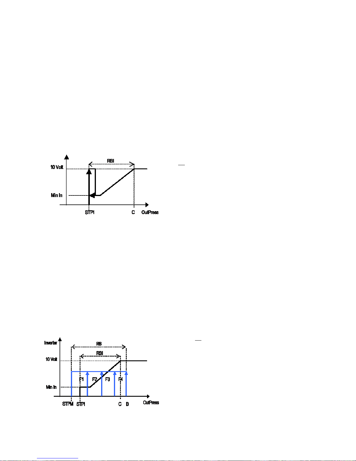
Inverter control
Proportional band
This control requires the inverter set point STPI to be set (parameter r18 ), plus an inverter differential RBI (parameter r19).
If the value measured by the discharge probe is less than or equal to the value of the inverter set point, the inverter output will be 0.
Between the inverter set point STPI and point C (set point + differential), the value of the inverter output will be proportional to the value read by the discharge probe,
and in any case not less than the minimum inverter output MinIn. If the value measured by the discharge probe is greater than or equal to the inverter set point +
differential, the output will be at the maximum value. The control is not associated with any fan and can work without fans being configured.
Proportional control, set by parameter r21, may be proportional only (parameter r21=0) or proportional + integral (parameter r21=1).
Key:
STPI Fan inverter set point
RBI Inverter differential
Min In Minimum inverter opening
C Fan set point + differential
Key:
RB Fan differential
RBI Inverter differential
STPM Discharge set point
STPI Inverter set point
C Inverter set point + inverter differential
B Discharge set point + Fan differential
Min In Minimum value of the inverter control output
Fig.5.d
Fig. 5.c

µRack
Cod. CAREL +03P220431 rel. 2.2 dated 10/02/12
20
Proportional and integral control (PI)
To minimise any deviations in stable operating conditions between the controlled value and the set point, typical of proportional control, a proportional plus integral
strategy (P+I) can be sued.
This strategy helps overcome situations of stalemate in which the working point remains steadily at a value other than the set point.
PI control adds the integral action to proportional control. This action, when a control error persists, has an increasing effect over time on the overall control action.
The parameter that defines the integral action is the integral time (r22).
The default value is 600 s (10 min). The integral time corresponds to the time taken by the integral action, with a constant error, to balance the proportional action.
The lower the integral time, the faster the response of the control.
For further information, refer to classic control theory.
N.B.: Make sure the integral time is not set too low, otherwise control may become unstable.
The following figure highlights the difference between the proportional control and proportional plus integral control (with inverter):
Proportional control Proportional + Integral control
T[s]
SP
RP
T[s]
10 Volt
Min In
T[s]
RP
SP
T[s]
10 Volt
Min In
Fig. 5.e
Key:
RP
Pressure read
SP Set point
T Time
Min In Minimum inverter output value
Dead band control
This control requires the setting of inverter set point, the inverter pressure differential for “dead band” control (parameter r21) and the “inverter ramp up time”
(parameter r28).
Three zones are defined: activation zone DOnZ, dead band NZ and deactivation zone DOffZ, in which the program behaves differently (see the figure).
In the activation zone DonZ, the fans are started as follows:
- The inverter is activated as soon as there is demand, with a value no less than the minimum inverter opening MinIn;
- The inverter output is increased according to the times set by parameter r23.
- If the inverter output reaches 100%, the situation persists
In the dead band NZ, the inverter output does not undergo any variation.
In the deactivation zone DoffZ, the fans are stopped as follows:
- The inverter output is progressively brought to the minimum value, according to the times set by parameter r24.
When reaching the minimum value, the fans are stopped.
Key:
InPress
Discharge pressure
B Set point + differential
StpM HP set point
DOnZ Activation zone
DOffZ Deactivation zone
NZ Dead band
T [s] Time
Inverter Inverter status
NFan Number of fans on
Fig. 5.f

µRack
Cod. CAREL +03P220431 rel. 2.2 dated 10/02/12
21
5.4 PWM-PPM management
On the controller, the “fan control” output generates a PWM signal.
This output is used to drive phase control modules that directly control the fan speed.
The output, depending on how it is configured, can generate a pulse width modulation (PWM) signal.
The example below shows two graphs representing the two modes.
In the graph, it can be seen that the request is 80% of the maximum value.
PWM
V
[5 Volt]
T[s]
80%
Fig. 5.g
The PWM signal controls, for example, the CAREL FCS* series, CONVONOFF, CON0/10A0 modules.
ON/OFF fan control board (code CONVONOFF0)
The CONVONOFF0 modules convert the PWM signal sent from terminal Y to an ON/OFF signal. In practical terms, Y can be used to control a relay. Switching power 10A
at 250 Vac in AC1 (1/3 HP inductive).
PWM to 0 to 10 Vdc (or 4 to 20 mA) conversion board for fans (code CONV0/10A0)
The CONV0/10A0 modules convert the PWM signal sent from terminal Y to a standard 0 to 10 Vdc (or 4 to 20 mA) signal.
Calculation of the minimum and maximum fan speed
This procedure should only be performed if fan speed control boards are used (code MCHRTF*0*0). It must be stressed that if the ON/OFF modules (code
CONVONOFF0) or the PWM / 0 to 10 V converters (code CONV0/10A0) or FCS are used, the “Min. triac” parameter (r29) should be set to zero, and the “Max. triac” r30
parameter to the maximum value is the impulse period (r31)=0.
Given the range of different motors existing on the market, the voltages supplied by the electronic board that correspond to the minimum and maximum speed can be
set. For this purpose (and if the default values are not suitable), proceed as follows:
1. Set the fan inverter to always On. Force inverter parameter, M17.
2. Set “Max triac” and “Min triac” to zero.
3. Increase “Max triac” until the fan operates at a speed considered sufficient (make sure that, after having stopped it, it starts rotating if left free);
4. “Copy” this value to the “Min triac” parameter; this sets the voltage corresponding to the minimum speed;
5. Connect a voltmeter (set for 250 V, AC) between the two “L” terminals (the two external contacts).
6. Increase “Max triac” until the voltage stabilises at around 2 Vac (inductive motors) or 1.6, 1.7 Vac (capacitive motors);
7. Once the optimum value is found, it should be seen that even when increasing “Max triac”, the voltage no longer decreases.
8. Do not increase “Max triac” any further, so as to avoid damaging the motor;
9. Set the force inverter parameter back to AUTO.
The operation is now complete.
5.5 Floating condenser control
If this function is enabled using parameter r32, the following parameters need to be set.
a) DELTA T (r33) (condenser exchanger parameter, typically related to the type of exchanger used)
b) Minimum condensing pressure (r25 in °C)
c) Maximum condensing pressure (r26 in °C)
The condenser set point is the value resulting from “DELTA T + Outside air temperature”, as with high outside temperatures the condensing temperature cannot be too
low (no possibility of energy savings). This is used to optimise the operation of the fans. The maximum and minimum pressure values are the range in which floating
control can operate.
ATTENTION: enabling this controller, the parameters “r16” (ventilation set) and “r18” (inverter ventilation set) are no more visibile since the relevant set point become
function of the external temperature + delta.
The following parameter are displayed in temperature always, not depending by used probe (pressure or temperature):
r17 (
Set the minimum value of suction probe)
r19 (
Fan inverter differential)
r25 (
Set the lower limit of the fan set point)
r26 (l Set the upper limit of the fan set point)

Cod.
C
6
6.1
The in
param
The o
n
The m
W
hen
If swit
c
Impo
r
6.2
Param
This p
a
Param
These
Param
The c
o
6.3
This f
u
An off
s
The o
f
6.4
By sel
e
The fo
6.5
The s
o
The t
w
No.
1
2
If the
a
Exam
p
AREL +03P22
0
V
arious s
e
Manual
d
dividual devices
c
eters Mxx.
ly support provi
d
anual activation
o
even just one m
a
hing the board o
f
tant: Use this fu
n
Compres
eter C07 is used
t
rameter is expre
s
eters C08 C10 C
1
parameters are a
l
eters C09 C11 C
1
mpressor maint
e
Set poin
t
nction is useful
w
et is added to th
e
fset can be defin
e
Type of
r
cting the type of
llowing table lists
Auxiliar
y
ftware can mana
g
o probes can be
Channel
N
B2 -
r
-
a
B3 -
o-a
uxiliary probe se
l
le of HT alarm
m
A
larm O
F
431 rel. 2.2 date
ttings
evice ope
r
an be activated
m
ed in manual op
e
f the speed cont
r
nual procedure i
s
ff and on again, t
h
nction with care
!
sor hour c
o
o set the alarm t
h
sed in the hund
r
12 C14 are used
t
so expressed in t
13 C15 are used
t
nance alarm is s
h
variation
hen needing to i
n
compressor set
d using paramet
e
efrigerant
refrigerant used i
the types of gas
m
probe ma
e two auxiliary t
e
configured with
p
TC probe
oom temperatur
e
uxiliary probe
utside temperat
u
uxiliary probe
ected, a high te
m
anagement
Fig. 6.
a
F
Set Poi
Diff. 2°
C
d 10/02/12
ation
anually, ignorin
g
ration is the alar
m
ollers sets the co
r
enabled, the “M
e function is ter
m
Operating the
d
unter an
d
reshold for the
m
eds of hours, as t
t
o check the nu
m
he tens of hours,
t
o reset each indi
v
own by an alarm
from digit
a
crease or decre
a
point when the
m
r R34.
n the installation
(
anaged:
Refrigera
n
R134a
R290
R600
R600a
R717
R744
R404A,R4
0
nagement
mperature prob
e
arameters /21 a
n
probe, read-onl
y
re probe for Floa
perature thresho
l
nt
A
larm O
N
the times and t
h
management f
u
responding outp
u
A
NUFACTURER”
i
inated.
evices manuall
y
maintena
n
aintenance of th
e resolution of t
h
ber of operating
h
as the resolution
idual hour coun
t
code, as well as
b
l input
se the set point
d
ultifunction inpu
t
parameter /35),
t
t
7C,R410A,R507
C
s, in addition to t
h
d /22:
t
ing condenser c
o
d can be set (par
temperature
22
e rotation, and i
unction.
ts to the maxim
u
con on the displ
a
may cause da
m
ce alarm
e 4 compressors.
he display is only
ours of the com
p
of the display is
o
er.
y the simultane
o
uring night-time
o
t, set for this fun
c
he software will
a
C
oTePrBu2-
AmCa M
Tab. 6.a
he suction and di
ntrol
Tab. 6.b
ameter A16, A17
ndependently fro
m value.
y will FLASH!
age to the insta
3 digits.
ressors installed
.
nly 3 digits.
us activation of t
h
peration.
tion, is closed.
utomatically calc
u
mplete name
trafluoroethane
opane
tane
methyl propane
(
monia (NH3)
rbon dioxide (C
O
ixes of gases
scharge probes.
)
. This alarm has
a
m the temperatu
r
llation!
e Maintenance a
late the conversi
o
isobutane)
2)
utomatic reset,
w
re control functio
nd Alarm icons.
on of the pressur
e
ith a fixed differ
e
ns, by setting the
to temperature.
ntial of 2°C.
µRack
related

µRack
Cod. CAREL +03P220431 rel. 2.2 dated 10/02/12
23
6.6 Prevent high discharge pressure
This function is enabled by parameter /32.
In order to prevent the activation of the general high pressure switch (total shutdown of the compressors, with manual reset), a “prevention” function can be enabled by
setting a pre-alarm threshold; this function gradually decreases the capacity of the unit.
The high pressure prevention (Prevent HP) function is only enabled during the activation and deactivation of the compressors.
If the discharge pressure exceeds the threshold set (parameter /33), the activation of any compressors is disabled and a prevent alarm is generated. In addition, all the
compressor load steps are deactivated, observing the times set for parameter C06.
If the discharge pressure falls below the Prevent threshold, any other compressor start calls are ignored, for a set time called Prevent time 1 (parameter A13).
If between the start of two prevent cycles a time less than Prevent time 2 (parameter A14) elapses, the “Excessive prevent frequency” alarm is generated, A29.
The “Excessive prevent frequency” alarm (display only) is reset automatically, if, within Prevent time 3 (parameter A15), the prevent function is not activated again. This
alarm can be reset manually by the user, momentarily disabling the PREVENT function, using parameter /32.
Fig. 6.b
Key:
OutPress
Discharge pressure
T Time
NCmp Number of suction steps required
ALPrv High pressure prevention alarm
STPpr Prevent HP activation threshold
T1 Time between compressor stops with prevent HP active
Dprev1 Step activation delay after end prevent HP (prevent time 1)
Dprev2 Minimum time for activation of high prevent frequency alarm (prevent time 2)
NCmp
OutPress
STPpr
T[s]
T[s]
1
2
3
4
Dprev1
T1
Dprev2
ALPrv
T[s]

Cod.
C
7
The a
c
comp
r
The al
a
in seq
u
(A19)
The al
a
7.1
W
hen
•
•
Press
t
If the
c
•
•
If, in t
h
The si
g
7.2
The c
o
W
hen
•
•
If the
c
remai
n
If, in t
h
If the
c
•
•
If, on
t
7.3
The l
o
(defa
u
7.4
Based
A dela
y
If the
t
Code
A01
A02
A03
A04
A05
A06
A07
A08
A09
A10
A11
A12
A13
AREL +03P22
0
Alarm ma
n
tivation of an ala
r
essors are called,
rm information
a
ence. If the alar
m
needs to be acce
s
rm from digital i
n
Alarms
w
one or more aut
o
Red ALARM L
E
Alarm relay ch
a
he PRG/MUTE b
u
ause of the alar
m
The alarm rela
y
Red ALARM L
E
is situation, new
nal will remain a
Alarms
w
mpressor therm
a
one or more ma
n
Red ALARM L
E
Alarm relay ch
a
ause of the alar
m
s in an alarm co
n
is situation, new
auses no longer
e
The alarm rela
y
Red ALARM L
E
he other hand, t
h
Semiaut
o
w pressure alar
m
lt 10 minutes), it
Alarm re
on the configura
t
y
time can be set
ime is set to 0, th
Alarm descriptio
n
Compressor 1
Compressor 2
Compressor 3
Compressor 4
Compressor 1 ma
Compressor 2 ma
Compressor 3 ma
Compressor 4 ma
Liquid level (from
m
General suction p
(from multifuncti
o
General suction p
(from multifuncti
o
General discharg
e
(from multifuncti
o
Low discharge pr
e
431 rel. 2.2 date
agement
m, from digital i
n
the activation of
a
ppears is display
e
situation is res
o
ssed.
put is typically d
ith autom
a
matic reset alar
m
D on;
nges, if enabled.
tton.
s is resolved, the
y
changes to nor
m
D goes off..
alarms are activa
t
ctive to leave a si
g
ith manua
l overload (para
m
ual reset alarms
D on;
nges, if enabled.
s has been res
o
dition and the d
e
alarms are activa
t
xist, the status o
f
y
changes to nor
m
D goes off..
e cause of the al
a
matic ala
r
from transduce
r
becomes an alar
m
lay
ion (no. of devic
e
(parameter A20)
e activation of th
e
intenance
intenance
intenance
intenance
ultifunction input)
ressure switch 1
n input)
ressure switch 2
n input)
pressure switch
n input)
ssure
d 10/02/12
put, causes the d
n alarm on one
d alternating wit
lved, the relay is
r
etected when the
tic reset
s are detected, t
h
devices that hav
e
al status;
ed, the initial situ
n of alarm ON,
u
l reset
eter /29) fan th
e
are detected, the
s
lved, the red LE
D
vices remain dis
a
ed, the initial situ
the signal devic
e
al status;
rms is still prese
n
ms
is a semiautom
a
that must be re
s < 5) relay no.
5
between the acti
v
alarm relay is i
m
Generated
b
DIN
DIN
DIN
DIN
---
---
---
---
DIN
DIN
DIN
DIN
AIN
irect action on th
e
ompressor send
s
the value read
b
eset and the alar
m
contact “opens”,
ese are signalled
shutdown will r
e
tion will return.
ntil the operator
rmal overload (p
a
e are signalled b
y
stays on to info
bled until the us
e
tion will return..
s changes as foll
o
t, the initial situa
t
tic alarm. It acts
set manually, tha
t
(multifunction)
c
ation of an alar
m
mediate.
y Action
p
Com
Com
Com
Com
COMP
O
COMP
O
A
ll co
m
A
ll f
a
24
devices involve
d
s the call to anot
h
y the control pr
o
m message is ca
n
however the logi
by:
start normal ope
manually sets th
e
arameter /30) al
a
:
rm the user that
r deleted the ala
r
ws:
ion will return.
as an alarm with
is, using param
e
an be used as a
n
and the change
erformed
p.1 OFF
p.2 OFF
p.3 OFF
p.4 OFF
/
/
/
/
/
FF CIRC 1
FF CIRC 2
ps. OFF
ns OFF
, at the same tim
er compressor.
be. If more than
o
celled. In the cas
e
c can be selected
ration, and the st
a
reset alarms par
a
rms can be set a
s
alarms have bee
n
m messages usi
n
automatic reset,
ter A19. This alar
alarm relay.
in the status of t
h
Type of reset
Settable
Settable
Settable
Settable
Settable
Settable
Settable
Settable
manual
automatic
automatic
Settable
automatic
e activating: the
L
ne alarm is activ
e
of alarms with
m
using the “digital
tus of the signal
d
meter A19.
manual reset.
activated durin
g
g parameter A19
however if it is a
obviously caus
e
e signal relay.
Delay
Settable
Settable
Settable
Settable
no
no
no
no
settable
no
no
no
settable
ED and a signal
o
e, the informatio
n
anual reset, the
input logic” para
devices changes
a
the day. In this
.
ctivated at least
3
es the unit to sh
u
Notes
n the display. If t
h
appears on the
d
Reset Alarms par
a
meter, /14.
s follows:
ituation, the ala
r
times within a
s
tdown.
µRack
e
isplay
meter
m relay
et time

µRack
Cod. CAREL +03P220431 rel. 2.2 dated 10/02/12
25
Code Alarm description Generated by Action performed Type of reset Delay Notes
A14 High discharge pressure AIN All fans ON automatic no
A15 Low suction pressure 1 AIN All comps. OFF automatic settable
A16 High suction pressure 1 AIN all comps. ON automatic settable
A17 Low suction pressure 2 AIN All comps. OFF automatic settable
A18 High suction pressure 2 AIN all comps. ON automatic settable
A19 Suction probe 1 faulty or disconnected AIN Settable no. comps. ON
automatic
30 seconds
See compressor management with probe
broken.
A20 Suction probe 2 faulty or disconnected AIN Settable no. comps. ON
automatic
30 seconds
See compressor management with probe
broken.
A21 Discharge probe faulty or disconnected AIN Settable no. fans ON
automatic
30 seconds Force fan inverter to 100%.
A22 Fan 1 thermal overload DIN Fan 1 OFF Settable no
A23 Fan 2 thermal overload DIN Fan 2 OFF Settable no
A24 Fan 3 thermal overload DIN Fan 3 OFF Settable no
A25 Fan 4 thermal overload DIN Fan 4 OFF Settable no
A26 General fan thermal overload DIN
Only signal alarm. Preset
electronically the fan stop
during overload
Automatic no
A27 Prevent high discharge pressure AIN Compressors OFF Automatic no
A28 Compressors off for Prevent HP AIN Compressors OFF Automatic no
A29 Excessive prevent frequency AIN / Settable no Display only
HtE High outside temperature AIN
Automatic No
HtA High ambient temperature AIN
Automatic No
EHS High supply voltage
--- OFF Automatic No
ELS Low supply voltage
--- --- Automatic No
EPb EEPROM error
--- --- Settable No
EL1 Zero cross
Power supply
voltage
100% Fans Automatic No
AB2 B2 probe error faulty or disconnected AIN --- Automatic No
AB3 B3 probe error faulty or disconnected AIN --- Automatic No
Tab. 7.a
7.5 Alarms from analogue inputs: temperature probe and pressure transducer:
Fixed differentials: 0.2 bar suction
1.0 bar discharge
Example of LP alarm management
Fig. 7.a
Example of HP alarm management
Fig. 7.b
High press.
Alarm off
Set Point
Alarm on
Diff.
Low press.
Alarm off
Set Point
Alarm on
Diff.

Cod.
C
8
µRack
In par
t
•••
•
In ad
d
Also s
e
8.1
For co
Serial
c
Produ
MRK0
0
MRK0
0
MRK0
0
8.2
Com
m
To en
a
(para
m
Each
c
•
•
For fu
r
9
The p
a
Displa
y
Displa
y
123
Once
t
of pro
t
IMPO
R
To ch
a1234
“_U_
”
“_I_”
“_C_
”
AREL +03P22
0
The super
v
can be connecte
d
icular, the followi
The status o
The status o
Alarms pres
e
Enabling of
t
ition, this functio
n
e the paragraph
Serial bo
nnection to supe
r
onnection optio
n
ct code
00000
000D0
00AD0
Commun
unication protoc
o
ble the correct o
p
eter /36).
ontroller must ha
There are N
O
The address
ther information,
User inter
f
rameters are divi
information tha
t
information tha
t
. USER para
m
. INSTALLER
of the devic
e
. MANUFAC
T
connected.
he password is
e
ection.
TANT:
nge the level of
p
. Once havin
g
. Then either
Parameters)
. If modifyin
g
value, but r
a
. Using the s
a
:parameters visi
b
:parameters visib
:parameters visi
b
431 rel. 2.2 date
v
isor netw
o
to the most co
m
ng data is exchan
f the inputs /out
p
f the devices ena
b
nt and active
t
he devices, vario
n allows the pos
s
Supervisor com
m
ards
visory systems, t
h
s:
RS485 ser
MCH2004
8
FCSER000
0
--------------
-
ication pr
o
l: CAREL.
eration of the c
o
ve the address s
e
other devices
w
es on the same s
e
refer to the corr
e
ace
ded into 2 categ
o
is NOT passwo
r
is password-pr
o
eters (password
parameters (pas
s
s.
URER paramete
r
ntered, it remain
s
arameter protect
entered the cor
r
press “SEL”, dir
e
.
the level, pressi
ther the level of
p
me procedure as
le at User level,
le at Installer lev
e
le at Manufactur
d 10/02/12
rk
mon supervisor
y
ged with the sup
e
uts
led
us settings etc.
ibility to modify
a
unication variabl
e
e control uses th
e
ial option Code
50
0
-
tocols
mmunication pr
o
t so that:
ith the same ad
d
rial line must be
sponding manua
ries.
d-protected: sh
o
tected:
22 modifiable by
word 44 modifia
b
s (password 77
m
in the memory
ion from the key
p
ect PWD MANUF
A
ctly accessing t
h
ng “SEL” accesse
rotection.
for modifying th
e
l,
er level.
systems, using s
u
rvisor:
series of param
s.
standard CARE
L
Notes
External op
t
Serial outp
u
µRack with
s
tocol, as well as i
ress on the same
set in progressiv
e
l or contact CARE
L
w the values of t
h
parameter /40):
s
le by parameter
/
odifiable by par
a
until automaticall
y
ad (from the MA
CTURER, the sy
s
e parameter m
e
s the parameter
parameters, cha
26
itable interface
b
eters from the s
u
RS485 serial pro
ion connected b
y
t board for DIN
v
erial option FCS
E
nstalling the boa
r
serial line
order, starting f
r
L.
e probes, alarm
s
et the main func
t
/41): periodical c
meter /42): conf
y
returning to th
e
NUFACTURER le
v
tem displays the
nu to change t
h
menu as describ
e
nge the level, ch
o
oards and proto
c
pervisor, such as
tocol.
cable to µRack c
o
ersion, to be fitte
R00000 already
F
d, a number of p
a
om 1.
.
ions of the devic
e
hecks on the dev
i
igure the compr
e
main screen, so
el only), proceed
string “S-P” (Set
P
e values or pres
d, where param
osing between t
h
ols.
: set point, differ
e
mpact
in the instrume
n
ITTED by CAREL
rameters need t
o
s connected (ti
m
ces, calibration o
f
ssor rack, enable
as to make it ea
s
as follows:
arameters);
“DOWN” or “
U
eters are scrolle
d
e 3 possible leve
l
ntials, times, uni
t
nt
be set, such as
t
es, set points, dif
f
f
the probes con
n
the main functio
n
ier to move aro
u
P” to display o
f
no longer displ
a
ls available:
t
status, reset ala
r
T
he identification
n
erentials);
ected, manual o
p
s and select the
nd within the sa
m
the string “L-P”
yed with the as
s
µRack
ms etc.
ab. 8.a
umber
eration
devices
e level
(Level-
ociated

Cod.
C
10
This ta
b
Param
e
Type:
(
Pos.: p
o
Descri
p
UOM:
u
Range:
Defaul
t
Notes:
IMPO
R
are di
s
USER
INST
A
PARA
M
MAN
U
PARA
M
Struct
u
Table
Param
e
Config
Type o
Mai
n
AREL +03P22
0
List of par
le contains the list
o
ter: description;
R) read-only, (R/W
)
sition: USER-INST
A
tion: synthetic des
c
nit of measure of
t
range of possible
v
: factory-set value
o
column available f
o
TANT: Not all t
h
played that we
r
PARAMETERS
LLER
ETERS
FACTURER
ETERS
re of the para
m
of parameter
s
ter
ration menu
f unit
synoptic chart:
LP1
LP2
HP
S2
S3
431 rel. 2.2 date
ameters
f all the paramete
r
read/write;
LLER-MANUFACTU
cription of the para
m
he value in questio
n
alues for the para
m
f the parameter.
r user notes.
e screens liste
d
e previously no
t
eters:
Type Pos.
D
R/W C
“
S
d 10/02/12
s, with the corresp
o
RER;
eter;
;
eter;
below will be d
available. The
d
+
Fig. 10.a
isplay Descripti
o
/00
Set the ty
p
0) LT
1) MT
2) TWO C
I
Password
-P” and “L-P”
parameters
“L-P”
visibility
nding description.
isplayed when s
isplay therefore
Press the SEL bu
t
Press the button
Press the P
THIS PASS
W
THE PARA
M
CHANGIN
G
n
e of unit, LT, MT or
RCUIT
27
crolling the disp
depends on th
e
t
ton for at least 5
PRG per at least
5
RG + SEL button
ORD OFFERS T
H
ETERS FOR PRO
THE LEVEL OF
P
two circuit
-/-
-C-
-r-
-A-
-M-
Pressi
lay; enabling a
c
initial configur
a
secs
secs
t
ogether for mor
e
E POSSIBILITY
O
GRAMMING THE
ROTECTION:
ng “PRG” for 3
ertain type of c
o
tion!
than 5 seconds
F DISPLAYING A
L
UNIT AND
UOM
seconds return
“S-P"=
S
“L-P”=
L
nfiguration will
P P
L
P
Range De
0 to 2
s to the main s
y
et Parameters
evel Paramete
r
mean that new
s
W 22
W 44
W 77
T
a
f
ault No
t
0
noptic.
s
µRack
creens
b. 10.a
t
es

µRack
Cod. CAREL +03P220431 rel. 2.2 dated 10/02/12
28
Parameter Type Pos. Display Description UOM Range Default Notes
Unit model R/W C /01
Set the unit model (without capacity control):
SINGLE CIRCUIT
0) 0 compressors
1) 1compressor
2) 2 compressors
3) 3 compressors
4) 4 compressors
TWO CIRCUIT
5) 1 compressor + 1 compressor
6) 2 compressors + 1 compressor
7) 3 compressors + 1 compressor
8) 2 compressors + 2 compressors
Set the unit model (with capacity control):
SINGLE CIRCUIT
9) 1 compressor 1 capacity control
10) 1compressor 2 capacity control
11) 1 compressor 3 parzializzazioni
TWO CIRCUIT
12) 1 compressor 1 capacity control + 1 compressor
13) 1 compressor 1 capacity control + 1 compressor 1 capacity control
14) 1 compressor 2 capacity control + 1 compressor
0 to 8 2
Compressors with different
capacities
R/W C /02
Enable management of compressors with different capacities
0) NOT ENABLED
1) ENABLED
0/1 0
For single circuit only
for the configuration
/01=1,2,3 e 4
Capacity compressor 1 R/W C /03 Capacity of compressor 1 kW 0 to 999 5
Only if comp. with
different capacities are
enabled
Capacity compressor 2 R/W C /04 Capacity of compressor 2 kW /03 to 999 10
Only if comp. with
different capacities are
enabled
Capacity compressor 3 R/W C /05 Capacity of compressor 3 kW
/03+/04 to
999
20
Only if comp. with
different capacities are
enabled
Capacity compressor 4 R/W C /06 Capacity of compressor 4 kW
/03+/04+/05
to 999
40
Only if comp. with
different capacities are
enabled
Number of compressors ON
with suction probe 1 fault
R/W C /07
If the suction 1 probe fault or not connected alarm is activated, this number
of compressors are started. These are in any case managed by the individual
alarms and general pressure switches.
0 to 4 0
Number limited by the
number of compressors
Number of compressors ON
with suction probe 2 fault
R/W C /08
If the suction 2 probe fault or not connected alarm is activated, this number
of compressors are started. These are in any case managed by the individual
alarms and general pressure switches.
0 to 4 0 For two circuits only
Configure number of fans R/W C /09 Set the number of fans 0 to 4 2
Number limited by the
number of compressors
already enabled
Enable fan inverter R/W C /10 Enable control of the fans with inverter 0/1 0
Display inverter output value R U /11 Display the inverter output as a percentage 0 to 100% 0
Number of fans ON with
probe fault:
R/W C /12
If the discharge probe fault or not connected alarm is activated, this number
of fans are started. These are in any case managed by the individual alarms
and general pressure switches..
0 to 4 0
Enable fans with compressors
ON
R/W C /13
0= independent operation of the fans
1= fans on only when at least one compressor is ON
0/1 0
Digital input logic: N.O. =No
alarm
R/W C /14
Set the logic of the digital inputs.
0) N.O.: with no alarm the contact is open
1) N.C. : with no alarm the contact is closed
0/1 1 NO / NC
Multifunction input
configuration
R/W C /15
Set the type of multifunction input:
0: no function
1) unit ON-OFF (NC contact ON)
2) change set point (set1- set2)
3) general high pressure switch NC
4) general high pressure switch NO
5) general low pressure switch 1 NC
6) general low pressure switch 1 NO
7) general low pressure switch 2 NC
8) general low pressure switch 2 NO
9) liquid level alarm NC
10) liquid level alarm NO
11) general fan thermal overload NC
12) general fan thermal overload NO
0 to 12
0
If the 4 outputs are
used, this parameter is
ignored and the
Multifunction Input is
set as fan thermal
overload
B1 probe type R/W C /16
B1 probe set:
0) probe not connected
1) NTC probe
2) 0 to 5 V probe
0 to 2 2
MIN suction pressure R/W C /17 Set the minimum value of suction probe bar -1.0 to /19 -1.0

µRack
Cod. CAREL +03P220431 rel. 2.2 dated 10/02/12
29
Parameter Type Pos. Display Description UOM Range Default Notes
MIN discharge/suction 2
pressure
R/W C /18 Set the minimum value of discharge probe/suction probe of second circuit bar -1.0 to /20 0
MAX suction pressure R/W C /19 Set the maximum value of the suction probe bar /17 to 45.0 9.3
MAX discharge/suction 2
pressure
R/W C /20
Set the maximum value of the discharge probe/suction probe of second
circuit
bar /18 to 45.0 34.5
B2 probe type R/W C /21
B2 probe set:
0) probe not connected
1) ambient air temp. probe / for two circuit, condenser probe
2) auxiliary temperature probe (used for HT alarm)
0 to 2 0
B3 probe type R/W C /22
B3 probe set:
0) probe not connected
1) outside air temp. probe
2) auxiliary temperature probe (used for HT alarm)
0 to 2 0
B4 probe calibration (suction) R/W I /23
Suction probe calibration
bar -12 to 12 0
B1 Probe calibration
(discharge)
R/W I /24 Discharge probe calibration bar -12 to 12 0
B2 probe calibration R/W I /25 Room probe calibration °C -12 to 12 0
B3 probe calibration R/W I /26 Outside probe calibration °C -12 to 12 0
Display probe R/W U /27
Probe displayed as default
0) probe B1
1) probe B2
2) probe B3
3) probe B4
0 to 3 3
Alarm relay logic R/W C /28
Logic of the alarm relay
0) NC
1) NO
0/1 1 If alarm relay enabled
Type of compressor thermal
overload alarm reset
R/W C /29
Type of thermal overload/generic alarm reset relating to the individual
compressor. Automatic: when the alarm stops, the compressor starts again.
Displayed only if the parameters are enabled
0) AUTO
1) MANUAL
0/1 1
Type of fan thermal overload
alarm reset
R/W C /30
Type of thermal overload/generic alarm reset relating to the individual fan.
Automatic: when the alarm stops, the fan starts again. Displayed only if the
parameters are enabled
0) AUTO
1) MANUAL
0/1 1
Type of general discharge
pressure switch reset
R/W C /31
Type of general high pressure switch reset
0) AUTO
1) MANUAL
0/1 0
Prevent high discharge
pressure
R/W C /32 Enable high discharge pressure prevention 0/1 0
Set point R/W C /33 High discharge pressure prevention set point bar 0 to 45.0 18.0 If prevent enabled
Refrigerant conversion R/W C /35
Type of refrigerant used
0) No refrigerant
1) R22
2) R134a
3) R404a
4) R407c
5) R410a
6) R507
7) R290
8) R600
9) R600a
10) R717
11) R744
0 to 11 3
Serial address R/W C /36
Supervisor configuration. Identification number of the µRack board for the
supervisor serial network
1 to 200 1
Delay restart after black out R/W I /37 Enable delay at start-up after a black out, with the set time. If 0 no delay s 0 to 999 0
Unit ON/OFF from the
supervisor
R/W I /38
Enable/disable unit from the supervisor.
0) OFF
1) ON
0/1 1
Unit ON/OFF by parameter R/W U /39
Enable/disable unit by parameter
0) OFF
1) ON
0/1 1
New User password R/W U /40 Used to change the password to access the User branch 0 to 999 22
New Installer password R/W I /41 Used to change the password to access the Installer branch 0 to 999 44
New Manufacturer password R/W C /42 Used to change the password to access the Manufacturer branch 0 to 999 77
B4 probe type R/W C /43
B4 probe set:
0) probe not connected
1)0 to 5 V probe
2) 0 to 5 V probe
0 to 2 2

µRack
Cod. CAREL +03P220431 rel. 2.2 dated 10/02/12
30
Parameter Type Pos. Display Description UOM Range Default Notes
Compressor menu
Min. compressor ON time R/W C C01 Minimum ON time for same compressor s 0 to 999 10
Min. compressor OFF time R/W C C02 Minimum OFF time for same compressor s 0 to 999 120
Min. time between starts of
different compressors
R/W C C03
Minimum time between two start calls for different compressors. Avoids
simultaneous starts
s 0 to 999 30
Min. time between stops of
different compressors
R/W C C04 Minimum time between two stop calls for compressors s 0 to 999 10
Min. time between starts of
same compressor
R/W C C05 Minimum time between two effective starts of the same compressor s 0 to 999 360
Time between compressor
OFF call with prevent active
R/W C C06 Time between compressor stop call with high pressure prevention active s 0 to 999 30
Only if
prevent active
Compressor operating hour
threshold for maintenance
alarm
R/W I C07
Compressor operating hour threshold for maintenance alarm. If set to 0, no
maintenance alarms.
h x 100 0 to 320 0
Compressor 1 operating hours R I C08 Display compressor 1 operating hours h x 100 0 to 320 0
RESET Compressor 1
operating hours
R/W I C09
Reset compressor 1 operating hours
0) NO RESET
1) RESET
0/1 0
Compressor 2 operating hours R I C10 Display compressor 2 operating hours h x 100 0 to 320 0
RESET Compressor 2
operating hours
R/W I C11
Reset compressor 2 operating hours
0) NO RESET
1) RESET
0/1 0
Compressor 3 operating hours R I C12 Display compressor 3 operating hours h x 100 0 to 320 0
RESET Compressor 3
operating hours
R/W I C13
Reset compressor 3 operating hours
0) NO RESET
1) RESET
0/1 0
Compressor 4 operating hours R I C14 Display compressor 4 operating hours h x 100 0 to 320 0
RESET Compressor 4
operating hours
R/W I C15
Reset compressor 4 operating hours
0) NO RESET
1) RESET
0/1 0
Control menu
Compressor set point circuit 1 R/W U r01 Compressor set point first circuit bar / °C r12 to r13 1.0
Compressor differential circuit
1
R/W U r02 Compressor differential first circuit bar /°C 0 to 20.0 0.5
Compressor set point circuit 2 R/W U r03 Compressor set point second circuit bar / °C r14 to r15 1.0 For two circuits only
Compressor differential circuit
2
R/W U r04 Compressor differential second circuit bar /°C 0 to 20.0 0.5 For two circuits only
Compressor rotation R/W C r05 Type of compressor rotation
0 = No rotation
1 = FIFO
2 = Time
1 For single circuit only
Compressor control R/W C r06
Type of compressor control:
0) Proportional
1) Dead band
2) Dead band with time
0/2 1
Min call time start in dead
band
R/W I r07 Set minimum call time for compressor starts in dead band s C03 to r08 20
Only if dead band
control is enabled
Max call time start in dead
band
R/W I r08 Set maximum call time for compressor starts in dead band s r07 to 999 60
Only if dead band
control is enabled
Min call time stop in dead
band
R/W I r09 Set minimum call time for compressor stops in dead band s 0 to r10 10
Only if dead band
control is enabled
Max call time stop in dead
band
R/W I r10 Set maximum call time for compressor stops in dead band s 0 to 999 60
Only if dead band
control is enabled
Dead band differential
pressure in which the time
varies
R/W I r11
Pressure differential in which the compressor start/stop time is proportional
to the suction pressure
bar /17…20,0 0.5
Only if dead band
control is enabled
Min compressor set point R/W C r12 Set the lower limit of the compressor set point circuit 1 bar /17 to r13 0.1
Max compressor set point R/W C r13 Set the upper limit of the compressor set point circuit 1 bar r12 to /19 9.3
Min compressor set point
circuit 2
R/W C r14 Set the lower limit of the compressor set point circuit 2 bar /18 to r15 0.1 For two circuits only
Max compressor set point
circuit 2
R/W C r15 Set the upper limit of the compressor set point circuit 2 bar r14 to /20 10 For two circuits only
Fan set point R/W U r16 Fan set point
bar
°C
r25 to r26
15.5
35.7
For single circuit only
Fan differential R/W U r17 Fan differential
bar
°C
0 to 20.0
0 to 20.0 3 18
For single circuit only
Inverter set point R/W U r18 Fan inverter set point
bar
°C
r25 to r26
15.5
35.7
Only if the inverter is
enabled

µRack
Cod. CAREL +03P220431 rel. 2.2 dated 10/02/12
31
Parameter Type Pos. Display Description UOM Range Default Notes
Fan inverter differential R/W U r19 Fan inverter differential
bar
°C
0 to 20.0
0 to 20.0 3 18
Only if the inverter if
enabled
Fan rotation R/W C r20
Type of fan rotation.
0) NO ROTATION
1) FIFO
0/1 1 For single circuit only
Fan control R/W C r21
Type of fan control:
0) Proportional
1) Proportional + integral
2) Dead band
0 to 2 0 For single circuit only
Integral time (P+I only) R/W C r22 Integral time with P+I control s 0 to 999 600 Only if PI
Time between fan start call R/W C r23 Minimum time between two successive calls to start different fans s 0 to 999 2 xx
Time between fan stop call R/W C r24 Minimum time between two successive calls to stop different fans s 0 to 999 2 xx
Min fan set point R/W C r25 Set the lower limit of the fan set point
bar
°C
0 to r26
-50 to r26
1.0
-31.2
Max fan set point R/W C r26 Set the upper limit of the fan set point
bar
°C
r25 to 40.0
r25 to 150
25.0
55.3
Fan inverter speedup time R/W C r27 Fan inverter speedup time s 0 to 999 2
Only if the inverter is
enabled
Inverter ramp up time R/W I r28 Set the time taken by the inverter to reach full load s 0 to 999 10
Only if the inverter is
enabled
Minimum fan inverter output R/W C r29 Set the minimum operation of the fan inverter % 0 to r30 0
Only if the inverter is
enabled
Maximum fan inverter output R/W C r30 Set the maximum operation of the fan inverter % r29 to 100 100
Only if the inverter is
enabled
Triac impulse duration R/W C r31 Duration of the impulse applied to the triac ms 0 to 10 0
Only if the inverter is
enabled
Enable floating condenser
control
R/W C r32
Enable the floating condenser control
0) NO
1) YES
0 to 1 0
Condensing Delta T R/W C r33 Temperature difference for floating condenser control -40 to 150 10
Compressor management
offset set point
R/W I r34
Compressor bar auxiliary set point offset.
Used when changing the set point from digital input
-99.9 to 99.9 0
Alarm menu
HP suction 1 alarm R/W I A01 Suction probe 1 alarm: high threshold setting bar A03 to /19 9.3
HP suction 1 delay R/W I A02 Suction probe 1 alarm: delay setting s 0 to 999 60
LP suction 1 alarm R/W I A03 Suction probe 1 alarm: low threshold setting bar /17 to A01 0
LP suction 1 delay R/W I A04 Suction probe alarm: delay setting s 0 to 999 60
HP suction 2 alarm R/W I A05 Suction probe 2 alarm: high threshold setting bar A07… /20 20 For two circuits only
HP suction 2 delay R/W I A06 Suction probe 2 alarm: delay setting s 0 to 999 60
LP suction 2 alarm R/W I A07 Suction probe 2 alarm: low threshold setting bar /18 to A05 0 For two circuits only
LP suction 2 delay R/W I A08 Suction probe alarm: delay setting s 0 to 999 60
HP discharge alarm R/W I A09 Discharge probe alarm: high threshold setting
bar
°C
A10 to /20
A10 to 150
20.0
45.8
LP discharge alarm R/W I A10 Discharge probe alarm: low threshold setting
bar
°C
/18 to A09
-50 to A09 0 -50
Discharge delay R/W I A11 Discharge probe alarm: delay setting s 0 to 999 60
Compressor thermal delay R/W I A12 Compressor thermal overload alarm: delay setting s 0 to 999 0
HP prevention
Prevent time 1
R/W I A13 Time in which start calls are ignored after prevent HP m 0 to 99 5
Only if the prevent is
enabled
HP prevention
Prevent time 2
R/W I A14
If two prevent alarms occur within this time, an excessive prevent frequency
alarm is generated
m 0 to 999 6
Only if the prevent is
enabled
HP prevention
Prevent time 3
R/W I A15
If no prevent alarms occur in this period, the high prevent frequency alarm is
automatically reset
m 0 to 99 30
Only if the prevent is
enabled
High temp. probe threshold:
B2
R/W I A16 High temperature threshold, probe B2 °C -40 to 150 100
High temp. probe threshold:
B3
R/W I A17 High temperature threshold, probe B3 °C -40 to 150 100
Delay liquid level alarm R/W I A18 Set the liquid level alarm delay from multifunction input m 0 to 500 60
Reset ALARMS R/W U A19
Reset the alarms with manual reset
0) NO RESET
1) RESET
0/1 0
Alarm signal delay R/W I A20 Set alarm signal delay s 0 to 999 1
Exchange auto->man LP 3
alarms
R/W I A21
On the 3rd activation, within the set time, the low pressure alarm from
pressure switch changes from automatic to manual reset.
m 0 to 999 10
OFF due to probe
disconnected
R/W I A22
Enable unit OFF due to probe disconnected/alarm
0) NO
1) YES
0/1 0
Maintenance menu

Cod.
C
Param
e
Enable
Enable
Enable
Enable
Force
c
Force
c
Force
c
Force
c
Enable
Enable
Enable
Enable
Force
f
Force
f
Force
f
Force
f
Force i
11
The C
O
The c
o
AREL +03P22
0
ter
compressor 1
compressor 2
compressor 3
compressor 4
ompressor 1
ompressor 2
ompressor 3
ompressor 4
fan 1
fan 2
fan 3
fan 4
an 1
an 2
an 3
an 4
nverter
ON/OFF f
a
NVONOFF0 mo
ntrol relay has a
s
431 rel. 2.2 date
Type Pos.
D
R/W I
R/W I
R/W I
R/W I
R/W I
R/W I
R/W I
R/W I
R/W I
R/W I
R/W I
R/W I
R/W I
R/W I
R/W I
R/W I
R/W I
n control
dules allow the
O
witching power
1
d 10/02/12
isplay Descripti
o
M01
Enable op
e
0) NO
1) YES
M02
Enable op
e
0) NO
1) YES
M03
Enable op
e
0) NO
1) YES
M04
Enable op
e
0) NO
1) YES
M05
Manually
o
0) NO
1) YES
M06
Manually
o
0) NO
1) YES
M07
Manually
o
0) NO
1) YES
M08
Manually
o
0) NO
1) YES
M09
Enable op
e
0) NO
1) YES
M10
Enable op
e
0) NO
1) YES
M11
Enable op
e
0) NO
1) YES
M12
Enable op
e
0) NO
1) YES
M13
Manually
o
0) NO
1) YES
M14
Manually
o
0) NO
1) YES
M15
Manually
o
0) NO
1) YES
M16
Manually
o
0) NO
1) YES
M17
Manually
o
0) NO
1) YES
board (co
d
N/OFF control of
0A at 250 Vac in
n
ration of compress
ration of compress
ration of compress
ration of compress
perate compressor
perate compressor
perate compressor
perate compressor
ration of fan 1 in a
u
ration of fan 2 in a
u
ration of fan 3 in a
u
ration of fan 4 in a
u
perate fan 1
perate fan 2
perate fan 3
perate fan 4
perate the inverter
e CONV
O
the condenser fa
AC1 (1/3 HP ind
u
32
or 1 in automatic
m
or 2 in automatic
m
or 3 in automatic
m
or 4 in automatic
m
1
2
3
4
utomatic mode:
utomatic mode:
utomatic mode:
utomatic mode:
at 100%
NOFF0)
ns.
ctive).
ode:
ode:
ode:
ode:
Fig. 11.a
UOM
Range De
0/1
0/1
0/1
0/1
0/1
0/1
0/1
0/1
0/1
0/1
0/1
0/1
0/1
0/1
0/1
0/1
0/1
f
ault No
t
1
1
1
1
0
0
0
0
1
1
1
1
0
0
0
0
0
Only if th
e
is dis
a
Ta
µRack
t
es
inverter
bled
b. 10.b

Cod.
C
12
The C
O
The F
C
13
The p
r
The k
e
for th
e
There
• Loa
d
• Cop
y
Warni
assist
t
IMPO
R
Refer
14
The c
o
The v
a
R
R/W
Analo
g
FRRRRRRRRRRRR
AREL +03P22
0
PWM to 0
NV0/10A0 mod
u
S series three-ph
Program
m
ogramming keys
ys must be conn
e
specific controll
e
are two main fun
the parameters
f
from the key to
o
ng: The paramet
e
he identification
o
TANT NOTE: T
h
t
o the program
m
Superviso
r
ntroller can be c
o
riables sent and
r
Read
Read-
W
rite
ue variables
low I
n
R
R
R
R
/W
/W
/W
/W
/W
/W
/W
/W
/W
/W
/W
/W
431 rel. 2.2 date
to 10 Vdc
les convert the
P
ase controllers ca
ing key (c
o
PSOPZKEY00 an
d
cted to the conn
r.
ctions, which are
rom a controller
t
ne or more con
t
rs can only be c
o
f the key to be u
e key can only
b
ing key instruct
manage
m
nnected to a loc
a
eceived by the s
u
S
e
R
e
dex
1
Probe
B
2
Probe
B
3
Probe
B
4
Probe
B
5
Suction
6
Differe
n
7
Suction
8
Differe
n
9
Min su
c
10
Max su
c
11
Min su
c
12
Max su
c
13
Fan set
14
Fan set
15
Fan dif
f
16
Fan dif
f
d 10/02/12
(or 4 to 2
0
WM signal sent f
r
n be connected t
o
de PSOP
Z
PSOPZKEYA0 fo
r
ector (4 pin AMP
)
selected using th
e
o the key (UPLO
A
rollers (DOWNL
O
pied only betwe
e
sed, CAREL has a
e used on µRa
c
ion sheet for fu
r
ent
l or remote supe
pervisor are sho
w
nd from the µRa
c
ceived and sent
f
4
1
2 (ambient air)
3 (outside air )
set point circuit 1
tial circuit 1
set point circuit 2
tial circuit 2
tion set point 1
tion set point 1
tion set point 2
tion set point 2
point
point
erential
erential
mA) con
v
om terminal Y o
n
the µRack with
o
KEYA0)
CAREL controlle
r
on the controlle
r
two dipswitches
D);
AD).
n instruments wi
t
plied a label tha
t
k controllers tha
ther details.
rvisor/telemainte
n
n in the tables b
e
k to the supervis
o
rom the µRack to
33
ersion bo
the µRack to a s
t
ut requiring this
m
s are used to co
p
rs, and can opera
t
(located under t
h
h the same prod
u
t
can used to des
c
t have the sam
e
ance system for
elow, with refere
n
r. Not modifiabl
e
the supervisor.
C
Descript
i
ard for fa
n
andard 0 to 10
V
odule.
y the complete s
e
t
e when the instr
u
e battery cover).
ct code. The upl
o
ribe the progra
m
firmware versi
o
managing the un
ce to the followi
n
an be modified
b
on
s (code C
O
dc (or 4 to 20 m
A
Fig. 1
2
t of parameters
t
ments are either
These are:
ad operation, o
n
ming made or th
n.
Fig. 13.a
t.
g key:
y the supervisor.
NV0/10A
0
) signal.
2
.a
o the µRack.
on or off, accord
the other hand,
e unit that the da
)
ing to the instruc
t
is always possibl
e
ta refers to.
Display c
o
LP1
HP/LP
2
B2
B3
r01
r02
r03
r04
r12
r13
r14
r15
r16 (ba
r
r16 (°C
)
r17 (ba
r
r17 (°C
)
µRack
ions
. To
de
)
)

µRack
Cod. CAREL +03P220431 rel. 2.2 dated 10/02/12
34
Flow Index
Description Display code
R/W 17
Min fan set point
r25 (bar)
R/W 18
Min fan set point
r25 (°C)
R/W 19
Max fan set point
r26 (bar)
R/W 20
Max fan set point
r26 (°C)
R/W 21
Fan inverter set point
r18 (bar)
R/W 22
Fan inverter set point
r18 (°C)
R/W 23
Fan inverter differential
r19 (bar)
R/W 24
Fan inverter differential
r19 (°C)
R/W 25
HP suction 1 alarm threshold
A01
R/W 26
LP suction 1 alarm threshold
A03
R/W 27
HP suction 2 alarm threshold
A05
R/W 28
LP suction 2 alarm threshold
A07
R/W 29
HP discharge alarm threshold
A09 (bar)
R/W 30
HP discharge alarm threshold
A09 (°C)
R/W 31
LP discharge alarm threshold
A10 (bar)
R/W 32
LP discharge alarm threshold
A10 (°C)
R/W 33
Probe B4 calibration
/23
R/W 34
Probe B1 calibration
/24
R/W 35
Probe B2 calibration
/25
R/W 36
Probe B3 calibration
/26
R/W 37
Min value suction probe
/17
R/W 38
Min value discharge probe
/18
R/W 39
Max value suction probe
/19
R/W 40
Max value discharge probe
/20
R/W 41
Set point prevent high pressure function
/33
R/W 42
Set point offset to change set from DI
r34
R/W 43
Differential pressure for dead band by time
r11
R/W 44
Condensing temperature delta for floating control
r33
R/W 45
High temp threshold probe B2
A16
R/W 46
High temp threshold probe B3
A17
Tab. 14.a
Digital variables
Flow Index Description Parameter
R/W 1 Unit on
R
2 Status of compressor 1
R
3 Status of compressor 2
R
4 Status of compressor 3
R
5 Status of compressor 4
R
6 Status of fan 1
R
7 Status of fan 2
R
8 Status of fan 3
R
9 Status of fan 4
R
10 Status of digital input 1
R
11 Status of digital input 2
R
12 Status of digital input 3
R
13 Status of digital input 4
R
14 Status of digital input 5
R/W 15 Reset alarms
A
19
R/W 16 Digital input logic /14
R/W 17 Alarm relay logic /28
R/W 18 Enable fan inverter /10
R/W 19
ON/OFF from supervisor
/38
R/W 20 Enable “prevent” control on condenser /32
R/W 21 Enable management of different compressors /02
R/W 22 Type of compressor reset /29
R/W 23 Type of fan reset /30
R/W 24 Type of reset for general high press. switch /31
R/W 25 Reset compressor 1 hours C09
R/W 26 Reset compressor 2 hours C11
R/W 27 Reset compressor 3 hours C13
R/W 28 Reset compressor 4 hours C15
R/W 29 Enable floating condenser control r32
R/W 30 Enable unit Off due to probe fault
A
22
R/W 31 Enable fans with compressor ON /13
Tab. 14.b

µRack
Cod. CAREL +03P220431 rel. 2.2 dated 10/02/12
35
Alarms sent to the supervisor
Tab. 14.c
Integer variables
Flow Index Description Parameter
R/W 1 Type of unit “/00” /00
R/W 2 Unit model “/01” /01
R
3 Number of compressors
R/W 4 Number of fans “/09” /09
R 5
Unit status
0 = Unit ON
1 = OFF from alarm
2 = OFF from supervisor
3 = OFF from remote input
4 = OFF from parameter
5 = Manual operation
6 = Install default
7 = PREVENT IN PROGRESS
R/W 6 Minimum call time for compressor start (dead band) r07
R/W 7 Minimum call time for compressor stop (dead band) r09
R/W 8 Minimum compressor ON time C01
R/W 9 Minimum compressor OFF time C02
R/W 10 Minimum time between starts of different compressors C03
R/W 11 Minimum time between starts of the same compressor C05
R/W 12 Reserved
R/W 13 Reserved
R/W 14 Liquid level alarm delay
A
18
R/W 15 Reserved
R/W 16 Number of compressors on in circuit 1 with probe damaged /07
R/W 17 Number of compressors on in circuit 2 with probe damaged /08
R/W 18 Number of fans on with probe damaged /12
R
19 Version of the application
R/W 20 Type of refrigerant /35
R/W 21 Capacity of compressor 1 /03
R/W 22 Capacity of compressor 2 /04
R/W 23 Capacity of compressor 3 /05
R/W 24 Capacity of compressor 4 /06
R
25 Inverter readout % “ /11
R/W 26 Multifunction DI configuration /15
R/W 27 B1 type probe /16
Flow Index Description
A
larm code
R
1 Alarm: compressor 1
A01R
2 Alarm: compressor 2
A02R
3 Alarm: compressor 3
A03R
4 Alarm: compressor 4
A04R
5 Alarm: fan 1
A22R
6 Alarm: fan 2
A23R
7 Alarm: fan 3
A24R
8 Alarm: fan 4
A25R
9 Alarm: liquid level
A
09
R 10
Alarm: general low suction pressure 1
(from multifunction DI)
A
10
R 11
Alarm: general low suction pressure 2
(from multifunction DI)
A11R
12 Alarm: low discharge pressure
A13R
13 Alarm: high discharge pressure
A14R
14 Alarm: low suction pressure 1”
A15R
15 Alarm: high suction pressure 1
A16R
16 Alarm: low suction pressure 2
A17R
17 Alarm: high suction pressure 2 “
A18R
18 Probe B1 faulty or disconnected
A20R
19 Probe B2 faulty or disconnected
AB2R
20 Probe B3 faulty or disconnected
A
B3
R
21 Probe B4 faulty or disconnected
A
19
R
22 Compressor 1 maintenance
A05R
23 Compressor 2 maintenance
A06R
24 Compressor 3 maintenance
A07R
25 Compressor 4 maintenance
A08R
26 General discharge pressure switch (from multifunction DI)
A12R
27 General fan thermal overload
A26R
28 Prevent high discharge pressure
A27R
29 Compressors off due to prevent
A28R
30 Excessive prevent frequency
A29R
31 High outside temperature HtE
R
32 High room temperature HtA
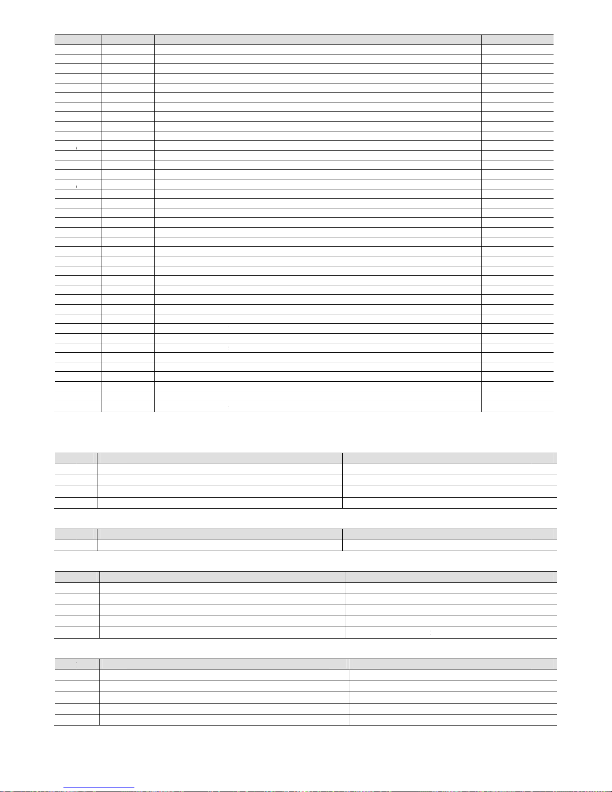
Cod.
C
Fl
oR/R/R/R/R/R/RRRR R/R/R/R/ R/R/R/R/R/R/R/R/R/R/R/R/R/R/R/R/R/R/R/R/R/R/
R
R
15
Sig
n
B
B
2B3
B
4
Sig
n
Y
Si
gIDIDIDIDID
Si
g
N
ONONONO
N
O
AREL +03P22
0
w In
dW 2W 2W 3W 3W 3W 3 3 3 3 3
/W 3W 3W 4W 4
/W 4W 4W 4W 4W 4W 4W 4W 4W 5W 5W 5W 5W 5W 5W 5W 5W 5W 5W 6W 6W 6W 6
6 6
Default c
o
al
1 Analogu
e
Analogu
e
Analogu
e
Analogu
e
al
PWM an
a
nal
1 N.C. dig
i
2 N.C. dig
i
3 N.C. dig
i
4 N.C. dig
i
5 N.C. dig
i
nal
1 Normall
y
2 Normall
y
3 Normall
y
4 Normall
y
5 Normall
y
431 rel. 2.2 date
ex
8 B2 typ
e
9 B3 typ
e
0 Delay r
1 Min ti
m
2 Time b
e
3 Operat
i
4 Compr
e
5 Compr
e
6 Compr
e
7 Compr
e
8 Type o
f
9 Type o
f
0 Maxim
u
1 Maxim
u
2 Type o
f
3 Type o
f
4 Integra
l
5 Time b
e
6 Time b
e
7 Inverte
r
8 Inverte
r
9 Minim
u
0 Maxim
u
1 Triac i
m
2 High s
u
3 Low su
4 High s
u
5 Low su
6 Low di
s
7 Compr
e
8 Preven
t
9 Preven
t
0 Time t
o
1 Alarm
s
2 Time t
o
3 B4 typ
e
5
Capaci
t
6
Capaci
t
nfiguratio
n
input 1
input 2
input 3
input 4
logue output
tal input no. 1
tal input no. 2
tal input no. 3
tal input no. 4
tal input no. 5
open contact, r
e
open contact, r
e
open contact, r
e
open contact, r
e
open contact, r
e
d 10/02/12
probe
probe
estart after black o
e between two st
o
tween compress
o
ng hour threshold
ssor 1 hours
ssor 2 hours
ssor 3 hours “
ssor 4 hours
compressor rotat
i
compressor cont
r
m call for compr
e
m call for compr
e
fan rotation
fan control
time for P+I fan
c
tween 2 fans star
t
tween 2 fans sto
p
speed up time
ramp up time
m inverter output
m inverter outpu
t
pulse duration
ction pressure 1 a
ction pressure 1 al
ction pressure 2 a
ction pressure 2 al
charge pressure a
ssor thermal ove
r
time in which no
time in which th
e
reset prevent ala
r
ignal delay
change low pres
s
probe
y percentage of fi
y percentage of s
e
s
Type of analog
Type of analog
u
Type of digi
t
Type of digi
t
lay no. 1
lay no. 2
lay no. 3
lay no. 4
lay no. 5
ut
p calls for differe
n
r stop call with Pr
e
for maintenance
on
ol
ssor starts in dead
ssor stops in dead
ontrol
s in dead band
s in dead band
%
%
larm delay
arm delay
larm delay
arm delay
arm delay
load alarm delay
compressor starts
activation signals
t
m
ure alarm from au
st capacity-contro
l
cond capacity-con
t
ue inputs
e outputs
al inputs
al outputs
36
Descripti
o
t compressors
vent function
band by time
band by time
are enabled
the alarm
tomatic to manua
l
led compressor w
t
rolled compresso
r
n
ith configuration /
0
without configur
a
Discharge
p
A
mbient ai
r
Outside air
Suction pre
s
Comp. 1 t
h
Comp. 2 t
h
Fan 1 ther
m
Fan 2 ther
m
General hi
Compres
Compres
Fan 1
Fan 2
Generic
a
1= 9,10,11,12,1
3
tion
/01= 9,10,11
ressure probe
temperature pro
b
t
emperature pro
b
sure probe
ermal overload
ermal overload
al overload
al overload
h pressure switc
h
or 1
or 2
larm
e 14
,12,13 e 14
Description
be
e
Description
Fan inverter
Description
h
Description
Paramete
r
/21
/22
/37
C04
C06
C07
C08
C10
C12
C14
r05
r06
r08
r10
r20
r21
r22
r23
r24
r27
r28
r29
r30
r31
A02A04A06A08A11A12A13A14A15A20A
21
/43
Ta
T
a
Ta
T
a
Ta
µRack
b. 14.d
b. 15.a
b. 15.b
b. 15.c
b. 15.d

Cod.
C
16
Analo
g
Buffer
Buzze
r
Digital
Differ
e
Discha
HP : Hi
Intege
r
LP : Lo
w
Propor
t
Range:
Step:
d
Set poi
Suctio
n
Uploa
d
17
“Gro
u
Power
12-pin
Relays
Digital
Analo
g
Fan o
u
Front
p
Storag
Opera
t
Degre
e
Cat. o
f
PTI of
Class
a
Period
Note:
A
Func
t
Resol
u
Temp
e
Press
u
AREL +03P22
0
Glossary
ue value: integer v
a
(memory): memor
y
: buzzer fitted on t
h
value: value with o
ntial: defines a pre
s
rge: pressure or te
m
gh pressure
value: integer val
u
pressure
t
ional band: this de
f
range of values av
a
efines an area of th
nt: defines a pressu
r
: pressure or temp
e
: the operation us
e
Technical
p A” is defined i
n
supply
connecto
r
inputs ID1 to ID
5
ue inputs
tput
anel index of pr
o
e conditions
t
ing conditions
of pollution
resist. to heat an
the insulating ma
nd structure of t
h
of electrical stres
ll the relays mu
s
t
ional specifi
c
tion of analogue
rature measure
m
re measurement
431 rel. 2.2 date
a
lue with minus sig
n
on the board use
d
e external terminal
s
nly two states.
sure (or temperatu
perature measure
d
e without decimal
p
f
ines a temperature
ilable for a parame
e proportional ban
d
e (or temperature)
v
erature measured a
d to copy the appli
c
specificati
o
the following sp
e
, IDB4
tection
d fire
terials
e software
s across the insul
a
t have the comm
ations
inputs
ent error
error
d 10/02/12
and decimal poin
t
to save the defaul
t
; this sounds in the
re) difference from
at the compresso
r
oint.
(or pressure) zone
o
ter.
(pressure or temp
alue to be satisfied;
t the compressor in
ation software fro
m
n
cifications as th
e
2
MFM
MEU
M
b
T
yInInInInInECMBTB
C
M
t
h
L
S
MIP-1-1ND≥A
ting parts l
o
ons (C1/2, C3/4)
TRR
T
.
values selected by
event of alarms or
the corresponding
s
outlet. This is an a
n
f a few degrees star
t
erature) inside whi
c
the system activate
s
t
ake. This is an anal
the computer or p
grouping of the
f
4 Vac, range –15
%
aximum current
use to be fitted in
ax current 2 A fo
ax current at 25
0
N60730: Resistiv
e
L: Resistive 3 A, 1
inimum interval
uilt into must en
s
y
pe of micro-swit
c
sulation betwee
n
sulation betwee
n
sulation betwee
n
sulation betwee
n
sulation betwee
n
lectrical standard:
losing current to
g
aximum closing
r
1, B2, B3, B4: CA
R
he response time
4: NTC temp. pr
o
ontrol signal for
C
odulation of im
p
e configuration
o
adless voltage:
5
hort-circuit curre
n
inimum output l
o
55
0T70°C - humidi
0T50°C - humidi
ormal
(UL94 V0)
250 V
ng
connected toget
h
emperature pro
b
ange -20T20 °C,
ange -40T80 °C,
he voltage % err
37
CAREL for all the p
a
the limits set for th
e
s
et point.
alogue value.
ing from the set poi
h a device is on, a
n
or deactivates the
d
ogue value.
rogramming key to
ollowing outputs
~ +10%; 50/6
output: 3 W
series with the p
r each relay outp
u
Vac:
: 3 A, Inductive:
2
FLA , 6 LRA cos
between switchin
ure the correct c
o
ching of the rela
y
relays in group
A
relays in group
A
relays in group
A
the signal relay
a
relays and the f
r
voltage-free con
t
ground: 5 mA
resistance: 50 W
REL NTC temper
a
depends on the
bes (10 kW at 2
5
AREL MCHRTF*
*
ulse position (se
t
f the parameters
V ± 10%
t: 30 mA
ad: 1 kW
ty <80% r.H., no
n
ty <90% r.H., no
n
er, as shown in
F
es: range -40T80
±0.5 °C (excludi
n
±1.5 °C (excludi
n
or in the input ra
n
rameters. Perman
e
parameters are ex
c
nt, inside which the
d at the same time
evices so that the v
a
the µRack.
: compressor 1, c
o
0 Hz
ower supply of t
h
t, extendable to
3
A cos (j)= 0.4 6
0
j)= 0.4 30000 cy
c
g cycles (each rel
nfiguration to re
s
: 1 C
: functional
and the very lo
w
and the signal r
e
nd the very low
v
ont panel: reinfo
r
act
ture probes (10
k
component used
,
°C) or CAREL 0
t
**, CONVONOF
F
amplitude) or m
-condensing
-condensing
ig. 1 e 2
°C, 0.1 °C
g probe)
g probe)
ge of 0.5 to 4.5
V
nt memory, saves t
h
eeded. The Built-in
ystem manages th
e
also defines the de
v
lue measured reach
mpressor 2, fan
e µRack: 315 mA
T
A for one outp
u
000 cycles
les
y): 12 s (the ma
n
pond to this spe
c
voltage parts: r
e
lay: primary
oltage parts: rein
ced
W at 25 °C)
typical value 90
s
o 5 V or free con
t
*, CONV0/10A*
a
dulation of the
d
dc is ± 2% (excl
u
e values even wh
e
terminals do not h
control devices.
ice on/off values.
es the set point.
1, fan 2, alarm.
T
t
nufacturer of the
ification)
inforced
forced
sec.
act ratiometric p
r
nd FCS modules
uty-cycle. Refer t
o
ding probe).
n power is disconn
e
ave a buzzer.
unit that the devi
c
essure probes
.
the user manu
a
µRack
cted.
e is
l for

Cod.
C
18
MRK0
MRK0
MRK0
The c
o
Polari
z
Polari
z
remo
v
remo
v
Acces
s
MCH
2
MCH
2 W
arni
MCH
S
MCH
S
MCH
S
MCH
S
MCH
2
FCSE
R
PSOP
Z
PSOP
Z
KIT
MRK
0
MRK
0
MRK
0
MRK
0
MRK
0
MRK
0
MRK
0
MRK
0
AREL +03P22
0
Product c
o
000000: μRack
p
0000D0: μRack
D
000AD0: μRack
D
nnectors kit cont
a
ed mini-fit conn
e
ed mini-fit conn
e
able terminal rig
h
able terminal rig
h
ories
CON001: conne
c
CON011: conne
c
ng: the connecto
r
MLCONM: mini-
f
MLCAB0: 24 cab
MLCAB2: 24 cab
MLCAB3: 24 cab
004850: RS485
s
00000: RS485 s
e
KEY00: program
KEYA0: progra
m
code
u
R
0010DK
D
00200K
p
0030DK
D
00400K
p
0050DK
D
00600K
p
0090DK
D
00800K
p
431 rel. 2.2 date
des list
anel mounting 3
2
IN rail mountin
g
IN rail mountin
g
ins:
ctor 2x6 pin fem
a
ctor 2x7 pin fem
a
t angle female 3
t angle female 3
tors kit for μChil
l
tors kit for μChil
l
s kit MCH2CON
*
f
it 2x6 and 2x7 pi
les kit 1 mm
2
, L=
les kit 1 mm
2
, L=
les kit 1 mm
2
, L=
erial board for p
e
rial board for per
ming key with 12
ming key with 2
3
ack RS485
IN
No
anel
No
IN
No
anel
No
IN
No
anel
No
IN No
anel No
d 10/02/12
x74, 24 Vac, wit
h
, 24 Vac, with co
n
, RS485 preinstal
l
le
le
pin, pitch= 3.81
m
pin, pitch = 5.08
m
er2/μRack panel
er2/μRack DIN r
a
contains a 2 pin
s
n connectors kit
1 m, preset for
m
2 m, preset for
m
3 m, preset for
m
r μRack panel m
o
μRack DIN rail
m
Vdc batteries inc
l
0 Vac external p
o
-1...4,2 bar
1
1
1
1
connectors kit
nectors kit
ed serial board,
2
m, high= 11.1
m
m, high= 11.1
m
mounting versio
n
il mounting versi
connector for th
e
ini-fit connection
ini-fit connection
ini-fit connection
unting version
ounting version
uded
wer supply
Ratiometric p
-1...9,3 bar
1
1
38
4 Vac, with conn
e
m
m (DIN version
on
e tLAN which is n
ressure probe
-1...12,8 bar
1
1
ctors kit
only)
ot used for μRac
k
0...34,5 bar
1
1
1
1
1
1
1
1
Cables for
pressure
probe
2
2
2
2
2
2
2
2
Connectors ki
t
DIN
panel
DIN
panel
DIN
panel
DIN
panel
2 m cables
MCHSMLC
A
No
No
Yes
Yes
Yes
Yes
Yes
Yes
µRack
kit
B2

Cod.
C
19
4 co
m
2 co
m
AREL +03P22
0
Append
pressors un
pressors un
431 rel. 2.2 date
ix: Com
p
it with fan sp
e
it + 2 conden
d 10/02/12
ressor
r
ed regulator
ser fans
ack con
t
39
roller,
e
Fig. 17.a
Fig. 17.b
C4C3C
2
F2 F1 C
2
xample
s
C1
C1
of application
d
iagrams
µRack

µRack
Cod. CAREL +03P220431 rel. 2.2 dated 10/02/12
40
3 compressors unit with 2 fan steps and speed regulator (no alarm relay output)
Fig. 17.c
2 compressors unit + 3 condenser fans
Fig. 17.d
F1 C3 C2
C1
F2
F1
C2 C1

Cod.
C
20
The la
t
Modifi
•••
•
In the
of the
The fo
/15:
/17:
/18:
/19:
/20:
/29:
/30:
/33:
/34:
/43:
The fo
C03:
C04:
C07:
C08:
C10:
C12:
C14:
The fo
r01:
r03:
r11:
r12:
r13:
r14:
r15:
r17:
r19:
r23:
r24:
r26:
The fo
A01:
A03:
A05:
A07:
A09:
A10:
A18 h
a
AREL +03P22
0
Appen
d
est FW release h
a
cations have bee
n
AS2 has be
e
AS3 has be
e
S3 has be
e
S4 has be
e
case of two refrig
first compressor i
llowing “/” para
m
The default val
The max. valu
e
The max. valu
e
The default val
The max. valu
e
The max. valu
e
The default val
The default val
The max. valu
e
The paramete
r
New paramet
e
The SONDA
_
Setting to 0
m
Settings 1 a
n
llowing “C” para
m
The default val
The default val
The compress
The max. valu
e
The default val
The max. valu
e
The max. valu
e
The max. valu
e
The max. valu
e
llowing “r” para
m
The min. valu
e
The max. valu
e
The min. valu
e
The max. valu
e
The min. valu
e
The min. valu
e
The default val
The max. valu
e
The min. valu
e
The max. valu
e
The default val
The default val
The default val
The times for
t
The times for
t
The max. valu
e
llowing “A” para
m
The default val
The max. valu
e
The default val
The default val
The max. valu
e
The default val
The max. valu
e
The default val
The min. valu
e
s been changed
The default val
The max. valu
e
431 rel. 2.2 date
ix: Cha
n
s changed from
made to the fol
l
n replaced by AB
n replaced by AB
n replaced by B2
n replaced by B3
erant circuits, a fi
x
n the second refr
eters have been
ue has been cha
n
is now /19
is now /20
ue has been cha
n
has been chang
e
has been chang
e
ue has been cha
n
ue has been cha
n
is now 45 bars
has been made
n
r for setting prob
e
_
B4 parameter n
o
eans the probe
d 2 mean it use
d
eters have been
ue has been cha
n
ue has been cha
n
or maintenance
has been chang
e
ue has been cha
n
has been chang
e
has been chang
e
has been chang
e
has been chang
e
eters have been
is now r12
is now r13
is now r14
is now r15
has been chang
e
has been chang
e
ue has been cha
n
has been chang
e
has been chang
e
has been chang
e
ue has been cha
n
ue has been cha
n
ue has been cha
n
he fans in the de
a
he fans in the de
a
has been chang
e
eters have been
ue has been cha
n
has been chang
e
ue has been cha
n
ue has been cha
n
has been chang
e
ue has been cha
n
has been chang
e
ue has been cha
n
has been chang
e
from seconds to
ue has been cha
n
has been chang
e
d 10/02/12
ges intr
o
1.7 to 2.0
owing strings:
2;
3;
;
.
ed delay of 4 se
c
igerant circuit.
modified:
ged from 3 to 0
ged from 4.1 ba
r
d from 40 bars t
d from 40 bars t
ged from 1 to 0
ged from 1 to 0
ot visible
B4.
w is visible and
c
is not used.
as a pressure pr
o
modified:
ged from 20 sec
ged from 20 sec
hour threshold
h
d from 999 (ho
u
ged from 200 (h
d from 999 (ho
u
d from 999 (ho
u
d from 999 (ho
u
d from 999 (ho
u
modified:
d from 0 to /17
(
d from 0 to /17
(
ged from 2.5 ba
r
d from 40 bars t
d from 0 to /18
(
d from 40 bars t
ged from 2.5 ba
r
ged from 0.5 ba
r
ged from 0.5 ba
r
d zone also appl
d zone also appl
d from 40 bars t
modified:
ged from 4 bars
d from 40 bars t
ged from 0.5 ba
r
ged from 4 bars
d from 40 bars t
ged from 0.5 ba
r
d from 40 bars t
ged from 10 bar
s
d from 0 bars (0
minutes:
ged from 90 sec
d from 999 sec
t
duced i
onds has been in
s to 9.3 bars
45 bars
45 bars
an be set on the
be.
to 30 sec
to 10 sec
as been increa
s
rs x 10) to 320 (
h
ours x 10) to 0 (
h
rs x 10) to 320 (
h
rs x 10) to 320 (
h
rs x 10) to 320 (
h
rs x 10) to 320 (
h
min value of suc
t
min value of suc
t
s to 9.3 bars
/19
min value of pro
b
/20 (max. valu
e
s to 10 bars
s (3°C) to 3 bars
s (3°C) to 3 bars
y
to the proporti
o
y
to the proporti
o
/20 (max. valu
e
to 9.3 bars
/19 (max. valu
e
s to 0 bars
to 9.3 bars
/20 (max. valu
e
s to 0 bars
/20
(20°C) to 0 bar
s
C) to /18 (-50°C
)
to 60 min
o 500 min
41
n Fw rel
troduced betwee
display and from
ed:
ours x 100)
ours x 100)
ours x 100)
ours x 100)
ours x 100)
ours x 100)
ion probe B4) (
m
ion probe B4) (
m
be B1) (min. valu
of suction prob
e
(18°C)
(18°C)
nal band (ZN on
l
nal band (ZN on
l
of suction prob
e
of suction prob
e
of suction prob
e
(-50°C)
)
ease 2.
0
n the start of the
f
the supervisor.
in. value of setp
o
in. value of setp
o
e of setpoint2 =
-
B1)
y indication rem
o
y indication rem
o
B1)
B4)
B1)
for MR
K
irst compressor i
n
int1 = -1.0 bars)
int1 = -1.0 bars)
1.0 bars)
ved)
ved)
0000XX
0
n the first refriger
a
nt circuit and th
e
µRack
start

Cod.
C
21
The la
t
Modifi
- arra
n
- arra
n
- cha
n
22
The F
W
The d
i
The “
S
New t
y
betwe
The f
o
/01:
Two i
n
int 65
int 66
CAR
E
AREL +03P22
0
Appen
d
est FW release h
a
cations have bee
n
ging of Speed-
U
ging of Floating
ge of
alarm del
a
Append
i
release has c
h
splay of variable
uction_Probe1
_
pes of units ha
v
en activation of
c
llowing “/” para
m
Range exten
d
teger variables
h
“Operating perce
n
“Operating perce
n
L reserves the ri
431 rel. 2.2 date
ix: Cha
n
s changed from
2
made to the fol
l
p Inverter mode
condenser cont
r
y to start-up; no
w
ce: mo
d
anged from 2.1
s relating to fan
s
Alarm”, “Suction
_
e been added t
o
apacity-control
s
eters have bee
n
ed from 0-8 to 0
-
ave been adde
d
tage of first cap
a
tage of second
c
ght to make mo
d
d 10/02/12
ges intr
o
.0 to 2.1
owing strings:
and calculation
o
ol;
, more than th
e
ifiche in
to 2.2
et point has be
e
Probe1_Alarm
a
increase the pr
o
teps is fixed (5
s
modified:
14
(visible to supe
city controlled co
m
apacity controlle
d
ifications or cha
n
duced i
f minimum and
value of the D
E
trodott
e
n corrected whe
nd “Discharge_
P
duct portfolio, w
i
econds).
visor only):
pressor in confi
g
compressor in c
o
ges to its produ
c
42
n Fw rel
maximum speed
LAY_START p
a
nella r
e
n the floating co
n
Probe_Alarm” al
a
ith the introducti
o
urations /01= 9,1
nfigurations /01=
c
ts without prior
ease 2.1
inverter;
rameter, is inclu
d
lease F
w
densing functio
n
rms have chan
g
n of single-circu
0,11,12,13 and 1
4
9,10,11,12,13 a
n
otice.
ed the delay im
2.2
is enabled and
ed from manual
t and two-circuit
”
d 14”
posed by their r
e
a condensing p
r
to automatic re
s
units with capa
c
lative paramet
e
essure probe is
u
et.
ity control; the ti
m
µRack
sed.
e


CAREL INDUSTRIES HQs
Via dell’Industria, 11 - 35020 Brugine - Padova (Italy)
Tel. (+39) 049.9716611 Fax (+39) 049.9716600
http: //www.carel.com - e-mail: carel@carel.com
Cod.: +03P220431 - µrack Rel. 2.2 10/02/12
 Loading...