


kVent
Controller for ventilation units
Manual
H i g h E f f i c i e n c y S o l u t i o n s
kVent – rel 3.1 – 22/06/2018
1

kVent – rel 3.1 – 22/06/2018
2

WARNING
KEY TO THE ICONS
IMPORTANT
CAREL bases the development of its products on decades of
experience in HVAC/R, on the continuous investments in
technological innovations to products, procedures and strict
quality processes with in-circuit and functional testing on 100% of
its products, and on the most innovative production technology
available on the market. CAREL and its subsidiaries nonetheless
cannot guarantee that all the aspects of the product and the
software included with the product respond to the requirements of
the final application, despite the product being developed
according to start-of-the-art techniques. The customer
(manufacturer, developer or installer of the final equipment)
accepts all liability and risk relating to the configuration of the
product in order to reach the expected results in relation to the
specific final installation and/or equipment.
CAREL may, based on specific agreements, acts as a consultant
for the positive commissioning of the final unit/application,
however in no case does it accept liability for the correct
operation of the final equipment/system.
The CAREL product is a state-of-the-art product, whose operation
is specified in the technical documentation supplied with the
product or can be downloaded, even prior to purchase, from the
website www.CAREL.com.
Each CAREL product, in relation to its advanced level of
technology, requires
setup/configuration/programming/commissioning to be able to
operate in the best possible way for the specific application. The
failure to complete such operations, which are required/indicated
in the user manual, may cause the final product to malfunction;
CAREL accepts no liability in such cases.
Only qualified personnel may install or carry out technical service
on the product.
The customer must only use the product in the manner described
in the documentation relating to the product.
In addition to observing any further warnings described in this
manual, the following warnings must be heeded for all CAREL
products:
• Prevent the electronic circuits from getting wet. Rain, humidity
and all types of liquids or condensate contain corrosive
minerals that may damage the electronic circuits. In any case,
the product should be used or stored in environments that
comply with the temperature and humidity limits specified in the
manual.
• Do not install the device in particularly hot environments. Too
high temperatures may reduce the life of electronic devices,
damage them and deform or melt the plastic parts. In any case,
the product should be used or stored in environments that
comply with the temperature and humidity limits specified in the
manual.
• Do not attempt to open the device in any way other than
described in the manual.
• Do not drop, hit or shake the device, as the internal circuits and
mechanisms may be irreparably damaged.
• Do not use corrosive chemicals, solvents or aggressive
detergents to clean the device.
• Do not use the product for applications other than those
specified in the technical manual.
All of the above suggestions likewise apply to the controllers,
serial boards, programming keys or any other accessory in the
CAREL product portfolio.
CAREL adopts a policy of continual development. Consequently,
CAREL reserves the right to make changes and improvements to
any product described in this document without prior warning.
The technical specifications shown in the manual may be
changed without prior warning.
The liability of CAREL in relation to its products is specified in the
CAREL general contract conditions, available on the website
www.CAREL.com and/or by specific agreements with customers;
specifically, to the extent where allowed by applicable legislation,
in no case will CAREL, its employees or subsidiaries be liable for
any lost earnings or sales, losses of data and information, costs
of replacement goods or services, damage to things or people,
downtime or any direct, indirect, incidental, actual, punitive,
exemplary, special or consequential damage of any kind
whatsoever, whether contractual, extra-contractual or due to
negligence, or any other liabilities deriving from the installation,
use or impossibility to use the product, even if CAREL or its
subsidiaries are warned of the possibility of such damage.
DISPOSAL
INFORMATION FOR USERS ON THE CORRECT HANDLING
OF WASTE ELECTRICAL AND ELECTRONIC EQUIPMENT
(WEEE)
In reference to European Union directive 2002/96/EC issued on
27 January 2003 and the related national legislation, please note
that:
• WEEE cannot be disposed of as municipal waste and such
waste must be collected and disposed of separately;
• the public or private waste collection systems defined by local
legislation must be used. In addition, the equipment can be
returned to the distributor at the end of its working life when
buying new equipment;
• the equipment may contain hazardous substances: the
improper use or incorrect disposal of such may have negative
effects on human health and on the environment;
• the symbol (crossed-out wheeled bin) shown on the product or
on the packaging and on the instruction sheet indicates that
the equipment has been introduced onto the market after 13
August 2005 and that it must be disposed of separately;
• in the event of illegal disposal of electrical and electronic
waste, the penalties are specified by local waste disposal
legislation.
Warranty of the materials: 2 years (from the date of production,
excluding consumables).
Approval: the quality and safety of CAREL INDUSTRIES Hqs
products are guaranteed by the ISO 9001 certified design and
production system.
: separate as much as possible
the probe and digital input signal cables
from the cables carrying inductive loads and
power cables to avoid possible
electromagnetic disturbance. Never run
power cables (including the electrical panel
wiring) and signal cables in the same
conduits.
The product must be installed with the earthconnected,
using the special yellow-green terminal on the terminal
block. Do not use the neutral for the earth connection.
NOTE: to bring attention to a very important subject;
in particular, regarding the practical use of the
various functions of the product.
IMPORTANT: to bring critical issues regarding the
use of the kVent to the attention of the user.
TUTORIAL: some simple examples to accompany
the user in configuring the most common settings.
Application TITLE – rel 1.0 – xx/xx/201x

kVent – rel 3.1 – 22/06/2018
4

CONTENTS
1. INTRODUCTION ............................................................................................................................................................................ 6
1.1 Main features ............................................................................................................................................................................. 6
1.2 Accessories available ................................................................................................................................................................ 6
2. HARDWARE INSTALLATION ......................................................................................................................................................... 7
2.1 Mounting and dimensions .......................................................................................................................................................... 7
2.2 Installation ................................................................................................................................................................................. 7
2.3 Field connection ........................................................................................................................................................................ 8
2.4 Input/Output ............................................................................................................................................................................... 9
3. SOFTWARE CONFIGURATION ................................................................................................................................................... 11
3.2 Unit schema............................................................................................................................................................................. 15
3.3 Board to point .......................................................................................................................................................................... 16
3.4 Software upgrade .................................................................................................................................................................... 16
4. USER INTERFACE ....................................................................................................................................................................... 18
4.1 Display PGDE .......................................................................................................................................................................... 18
4.2 Menu description ..................................................................................................................................................................... 18
4.3 Display th-Tune ....................................................................................................................................................................... 19
4.4 User setpoint ........................................................................................................................................................................... 20
5. FUNCTIONS ................................................................................................................................................................................. 21
5.1 Input functions ......................................................................................................................................................................... 21
5.2 On request ............................................................................................................................................................................... 21
5.3 Cooling/Heating changeover .................................................................................................................................................... 21
5.4 Temperature regulation strategy .............................................................................................................................................. 21
5.5 Fresh air regulation .................................................................................................................................................................. 22
5.6 Humidity regulation .................................................................................................................................................................. 22
5.7 Devices activation .................................................................................................................................................................... 22
5.8 Freeze and frost protections .................................................................................................................................................... 24
5.9 Fans control ............................................................................................................................................................................. 24
5.10 Mixing chamber control ............................................................................................................................................................ 25
5.11 CO2 Regulation ........................................................................................................................................................................ 25
5.12 Boost function .......................................................................................................................................................................... 25
5.13 Minor functions ........................................................................................................................................................................ 25
5.14 Import/Export parameters ........................................................................................................................................................ 25
6. PARAMETERS TABLE ................................................................................................................................................................. 26
6.1 INFO menu in main mask ........................................................................................................................................................ 26
6.2 SET menu in main mask .......................................................................................................................................................... 29
6.3 MODE menu in main mask ...................................................................................................................................................... 31
6.4 HEATING menu in main menu ................................................................................................................................................. 31
6.5 COOLING menu in main menu ................................................................................................................................................ 32
6.6 COOL/HEAT menu in main menu ............................................................................................................................................ 33
6.7 FANS menu in main menu ....................................................................................................................................................... 34
6.8 RECOVERY menu in main menu ............................................................................................................................................. 34
6.9 HUMIDITY menu in main menu ............................................................................................................................................... 35
6.10 IN/OUT SETTINGS menu ........................................................................................................................................................ 36
6.11 SETTINGS menu in main menu ............................................................................................................................................... 43
6.12 UNIT CFG. menu in main menu ............................................................................................................................................... 44
7. ALARMS ....................................................................................................................................................................................... 45
7.1 Alarms interface ....................................................................................................................................................................... 45
7.2 Table of alarms ........................................................................................................................................................................ 46
8. NEW FUNCTIONALITIES FROM VER. 2.1.0 ................................................................................................................................ 48
8.1 Modulating Fresh air damper ................................................................................................................................................... 48
8.2 Additional device signals to send a feedback to external devices ............................................................................................. 48
8.3 Advanced PID settings for the working modes ......................................................................................................................... 48
8.4 HEPA filters management ........................................................................................................................................................ 48
8.5 Regulation CAV and VAV in supply only units .......................................................................................................................... 48
8.6 FieldBus frame configuration ................................................................................................................................................... 48
9. NOTE .................................................................................................................................................................................................. 49
9.1 kVent release notes ...................................................................................................................................................................... 49
kVent – rel 3.1 – 22/06/2018
5

Regulation
Scheduler
R
ecovery
Coils
Fans
Protection
I
nterface
Languages
Unit of
Alarms
Fieldbus1
Ethernet port
1. INTRODUCTION
1.1 Main features
Usability and display – kVent, developed in line with the new
CAREL usability standards, assists the manufacturer in the
configuration of the installation. The menu-based system allows
the application to be configured as a tool for instant diagnostics. All
this is possible by the immediately accessible overview screens
and the commissioning tool.
Quick menus - information on the status of the kVent is accessible
directly from the main menu, without needing to access the
submenus. Configuration, active function and operating
temperature information are arranged in loops of screens, scrolled
by pressing the DOWN button from the main screen.
Main features
measure
Temperature PID regulation based on supply
Humidity PID regulation based on supply or
room humidity
Automatic cooling/heating changeover
Setpoint compensation
VOC and CO2 regulation
4 time bands for each day
3 special periods
6 special days
Rotary heat recovery
Glycol heat recovery
Plate cross-flow recovery
Hydronic systems
Electric heating
Direct expansion
Steam coil
Reverse coil
ON/OFF fan
3 speeds setup
Air pressure control
Air flow control
Filters
Fire/Smoke alarm
Frost protection
Door switch
Browser interface based on WebKit
pGDE for advanced function and service
thTune for end user
3 different parameters access levels
EN, PL, RU, CZ
International
USA
CAN
UK
Automatic and manual management
Log from application
Modbus Master Line
Modbus slave built-in
Bacnet built-in
tEra ready
WebServer / c.field for commissioning
1.2 Accessories available
Below is a list of devices suitable for use with this product. CAREL
features passive, active and serial temperature, humidity and
differential pressure probes, for room or duct installation,
specifically for the air handling unit appliance.
Duct temperature and humidity sensor
(Technical leaflet +050001245)
Outdoor sensors
(Technical leaflet +050001790)
NTC temperature sensors
(Manual +030220655)
PT1000 temperature sensors
(Manual +030220655)
Room air quality sensors
(Technical leaflet +050001300)
Differential air pressure sensors
(Technical leaflet +050000651)
Differential air pressure switches/flow
switches
(Technical leaflets +050000645 +050000647)
Smoke and fi re sensors
(Technical leaflet +050000520)
pGDE terminal
(Technical leaflet +050001050)
pLDPRO terminal
(Technical leaflet +050001840)
thTune terminal
(Technical leaflet +0500017IE)
Fans VFD inverter
(Technical leaflet +050001230)
kVent – rel 3.1 – 22/06/2018
6

2. HARDWARE INSTALLATION
2.1 Mounting and dimensions
The controller is designed to be mounted on a DIN rail. The figure
below shows the dimensions.
2.2 Installation
Environmental conditions
2.2.1
Avoid installing the controller and the terminal in places with:
• exposure to direct sunlight and to the elements in general;
• temperature and humidity outside the product’s range of
operation (see “Technical Specifications”);
• large, rapid fluctuations in room temperature;
• strong magnetic and/or radio frequency interference (avoid
installing near transmitting antennas);
• strong vibrations or knocks;
• presence of explosives or flammable gas mixtures;
• exposure to aggressive and polluting atmospheres (e.g.
sulphur and ammonia vapours, salt mist, fumes) that can
cause corrosion and/or oxidation;
• exposure to dust (formation of a corrosive patina with
possible
• oxidation and reduced insulation);
• exposure to water.
Positioning the controller inside the panel
2.2.2
Install the controller inside an electrical panel in a position where it
cannot be reached and is protected from knocks or impacts. The
controller should be placed inside the panel in a position where it is
physically separated from power components (solenoids,
contactors, actuators, inverters, etc.) and their respective cables.
The ideal solution is to house these two circuits in two separate
cabinets. Proximity to such devices/cables may cause random
malfunctions that are not immediately evident. The panel’s casing
must allow an adequate flow of cooling air.
Attention:
• For safety reasons the controller should be installed inside an
electrical panel so that the only accessible parts are the
display and the built-in terminal’s keypad.
• Install the controller so that the disconnection devices can be
used safely and without hindrance.
• When laying out the wiring, separate as much as possible the
probe cables, digital input cables and serial line cables from
the power cables (connected to contactors, thermomagnetic
devices, etc.) avoid electromagnetic interference.
• Never run power cables and probe signal cables in the same
conduits (including the ones in the electrical panels).
• For control signals, use shielded cables with twisted wires. If
the control cables have to cross over power cables, the
intersections should be as close as possible to 90 degrees;
under no circumstances should the control cables be laid
parallel to the power cables.
• Keep the paths of the probe cables as short as possible and
avoid making spiral paths that enclose power devices.
• In case of malfunctions do not attempt to repair the device,
but contact a CAREL service centre.
Electrical installation
2.2.3
Attention: Before servicing the equipment in any way
disconnect the controller from the power mains by putting the
system’s main switch on OFF.
Make sure the system is provided with a power disconnector
conforming to regulations. Use cable lugs that are suitable for the
terminals used.
Loosen each screw and insert the cable lugs, then tighten the
screws.
There is no limit to the number of wires that can be connected to
each individual terminal. When tightening the terminal screws
apply a tightening torque no greater than 0.6 Nm. For information
on the maximum allowable length of the connections to the
analogue/digital inputs and to the analogue outputs please refer to
the “Technical Specifications” table. In environments subject to
strong disturbance use shielded cables with the braiding bonded to
the earthing conductor in the electrical panel. The terminals can
accept wires with a maximum cross-section of 2.5 mm2 (12 AWG).
After making the connection, gently tug on the cables to make sure
they are sufficiently tight.
Note:
• secure the cables connected to the controller with clamps
placed at 3cm from the connectors;
• if the power transformer's secondary winding is earthed,
make sure the earth conductor is bonded to the conductor
that goes to the controller and is connected to terminal G0.
This applies to all the devices connected to the controller
through a serial network.
Attention:
• Using a supply voltage other than specified can seriously
damage the system.
• Installing, servicing and inspecting the controller should be
done only be qualified personnel and in compliance with
national and local regulations.
• All the very low voltage connections (24 Vac/Vdc or 28 to 36
Vdc
• analogue and digital inputs, analogue outputs, serial bus
connections, power supplies) must have reinforced or double
insulation from the power mains.
• Avoid touching or nearly touching the electronic components
mounted on the boards to avoid electrostatic discharges from
the
• operator to the components, which can be very damaging.
• Do not press the screwdriver on the connectors with
excessive force, to avoid damaging the controller.
• Using the device in any way other than specifi ed by the
Manufacturer can compromise its protection system.
• Use only optional boards and connectors supplied by CAREL.
kVent – rel 3.1 – 22/06/2018
7
on port
DISP
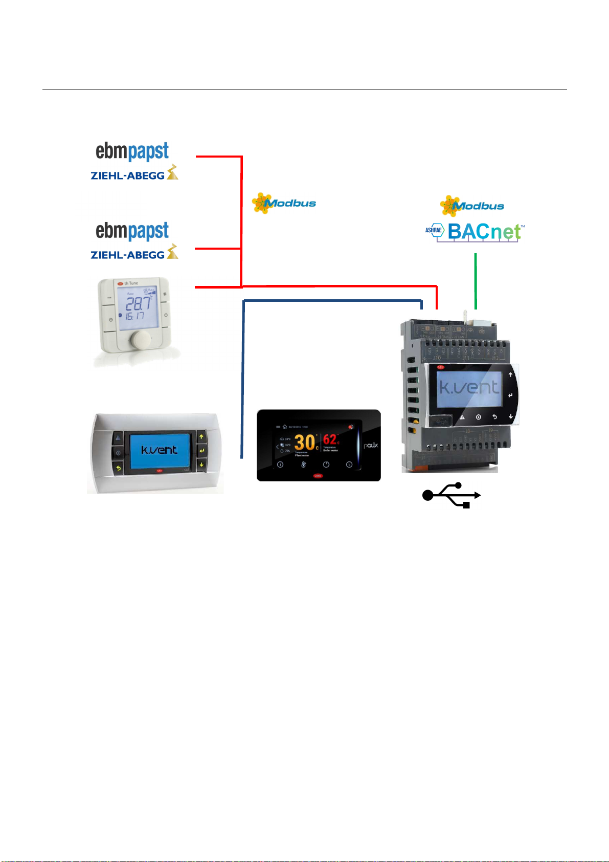
2.3 Field connection
Return fan
Addr. 11
Supply fan
Addr. 12
ModBus® master
protocol on port FB
thTune
Addr. 1
Display protocol
Default frame FieldBus port for ModbusMaster 19200 8N2.
With the following parameters is possible to define a different Frame:
Ha91: Stop bits
Ha92: Parity
kVent – rel 3.1 – 22/06/2018
8

Ref. Description
Acronym
Description
Value
Default
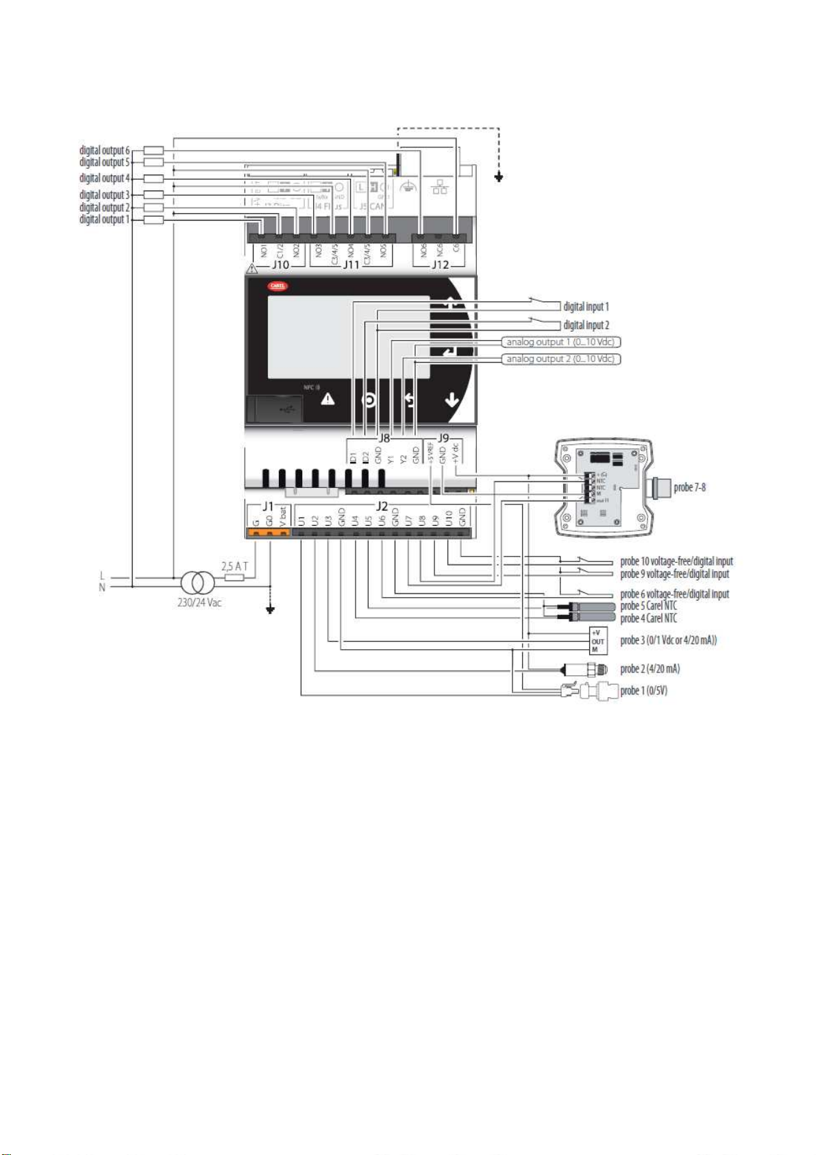
2.4 Input/Output
Connections terminals
2.4.1
Universal I/O In U NTC input 10
In U PT1000 input 10
In U PTC input 10
In U PT500 input 10
In U PT100 input 5
In U
In U
In U
In U
In U
In U
In U Fast digital inputs 2
TOTAL UNIVERSAL 10
Digital inputs In DI Voltage-free contacts 2
TOTAL DIGITAL INPUTS 2
Analog
outputs
Analog
outputs
Analog
outputs
TOTAL ANALOG OUTPUTS 2
Digital outputs Out NO/NC relay output 1
Out NO relay output 5
TOTAL DIGITAL OUTPUTS 6
In/Out
Out U
Out U
Out Y
Out Y
Out Y
Label
Type
0 to 1 Vdc/0 to 10 Vdc input
(powered by controller)
0 to 1 Vdc/0 to 10 Vdc input
(external power supply)
0 to 20 / 4 to 20mA input
(powered by controller)
0 to 20 / 4 to 20mA input
(powered externally)
0 to 5 V input for ratiometric
probe (+5Vref)
Digital input w/ voltage-free
contact
0 to 10 Vdc output, not
opticallyisolated
PWM output, not opticallyisolated
0 to 10 Vdc output, not
opticallyisolated
PWM output, not opticallyisolated
Output for single-pole
stepper motor
0
10
2
4
2
10
5
10
2
2
1
kVent
1 Power connector G(+), G0(-)
2 Vbat: terminal for external Ultracap module (accessory)
3 Universal inputs/outputs
4 +Vterm: terminal power supply
5 Terminal connector
6 Relay digital outputs
8 +5VREF: power supply for ratiometric probes
+VDC: power supply for active probes
9 FieldBus connector
10 BMS connector
11 Analogue outputs
12 Digital inputs
13 CANbus connector
14 Ethernet port
thTune addressing
2.4.2
thTune communicates with the controller throu ModBus network,
so the slave devices must have different ModBus address.
To configure ModBus address of thTune, press buttons
FAN+ON/OFF for 3s, then enter password 22. Parameters are:
kVent – rel 3.1 – 22/06/2018
Addr ModBus address 1 1
bAud Baudrate 2 2
9
Connections example
2.4.3
kVent – rel 3.1 – 22/06/2018
10

Unit setup
Control type
Mandatory I/O
Not available I/O
Recovery
Main-Heater
Recovery
Main
-
Heater
Main
-
Cooler
Reversible
Preheater
R
eheater
Economizer
Humidifier
Hardware
Fa
n type
Recovery control
Heating devices
Cooling devices
Reversible devices
Preheater devices
Reheater devices
Economizer device
Supply regulation
Return regulation
3. SOFTWARE CONFIGURATION
Attention: Structure of the software in class A: the thermal protection safeties for overload and high pressure must act directly on the
actuators and are thus wired in series with the command for coil of the actuators contactors.
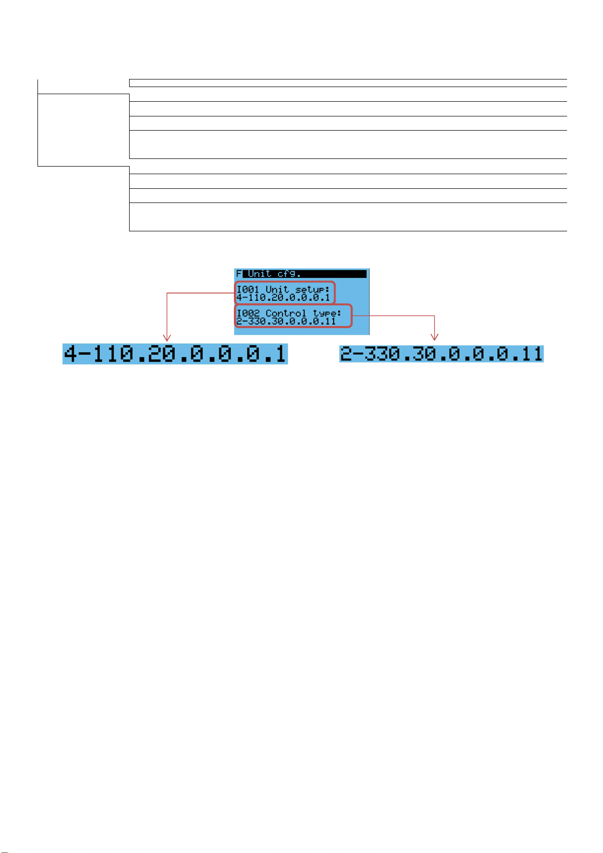
The software configuration procedure includes these steps:
1. Configure unit setup unique code in Unit config. menu (I001)
2. Configure control type unique code in Unit config. menu (I002)
3. Assign inputs/outputs with board to point function (menu G)
4. Set regulation and optional parameters
5. Set unit in RUN mode (I003)
Unit setup
3.1.1
To configure the unit is enough to setup an unique application code that determines the devices present on the unit. Here an example of
application code and its meaning and the possible combination on the table.
0 Supply only Supply temperature (AI1)
1 Supply + Exhaust Supply temperature (AI1)
2 Rotary wheel
1 0-10V valve control
2 3 point valve control
3 2 steps control
4 ON/OFF control
3 Glycol
4 Plate cross
1 0-10V valve control
2 3 point valve control
3 2 steps control
4 ON/OFF control
0 None
1 Hot water
1 0-10V valve control
2 3 point valve control
3 0-10V valve in common with cool
kVent – rel 3.1 – 22/06/2018
Supply temperature (AI1), Exhaust
temperature (AI4), Fresh temperature (AI3),
Modulating recovery (AO6)
Supply temperature (AI1), Exhaust
temperature (AI4), Fresh temperature (AI3),
Recovery 3point valve (DO23, DO24)
Supply temperature (AI1), Exhaust
temperature (AI4), Fresh temperature (AI3),
Recovery 2 steps (DO36, DO37)
Supply temperature (AI1), Exhaust
temperature (AI4), Fresh temperature (AI3),
Recovery ON/OFF (DO10)
Supply temperature (AI1), Exhaust
temperature (AI4), Fresh temperature (AI3),
Recovery ON/OFF (DO10)
Supply temperature (AI1), Exhaust
temperature (AI4), Fresh temperature (AI3),
Modulating recovery (AO6)
Supply temperature (AI1), Exhaust
temperature (AI4), Fresh temperature (AI3),
Recovery 3point valve (DO23, DO24)
Supply temperature (AI1), Exhaust
temperature (AI4), Fresh temperature (AI3),
Recovery 2 steps (DO36, DO37)
Supply temperature (AI1), Exhaust
temperature (AI4), Fresh temperature (AI3),
Recovery ON/OFF (DO10)
Back water temperature (AI6), Fresh
temperature (AI3), Freeze alarm (DI8), Heat
1 (DO4), Modulating heat (AO3)
Back water temperature (AI6), Fresh
temperature (AI3), Freeze alarm (DI8), Heat
1 (DO4), Heat 3 point valve (DO17, DO18)
Back water temperature (AI6), Fresh
temperature (AI3), Freeze alarm (DI8), Heat
1 (DO4), Cool/Heat common (AO12)
11
Exhaust temperature (AI4), Exhaust air pressure (AI14), Exhaust air
filter (DI15), Exhaust air damper (DO9), Recovery (DO10, DO36,
DO37, DO23, DO24, AO6), Exhaust fan (DO15)
Exhaust temperature (AI4), Recovery (DO10, DO36, DO37, DO23,
DO24, AO6)
Recovery 3point valve (DO23, DO24),
Recovery 2 steps (DO36, DO37)
Recovery 2 steps (DO36, DO37), Modulating recovery (AO6)
Recovery 3point valve (DO23, DO24), Modulating recovery (AO6)
Recovery 3point valve (DO23, DO24), Modulating recovery (AO6),
Recovery 2 steps (DO36, DO37)
Modulating recovery (AO6, DO36, DO37, DO23, DO24)
Recovery 3point valve (DO23, DO24),
Recovery 2 steps (DO36, DO37)
Recovery 2 steps (DO36, DO37), Modulating recovery (AO6)
Recovery 3point valve (DO23, DO24), Modulating recovery (AO6)
Recovery 3point valve (DO23, DO24), Modulating recovery (AO6),
Recovery 2 steps (DO36, DO37)
Back water temperature (AI6), Freeze alarm (DI8), Heat alarm
(DI9), Heat 1 (DO4), Heat 2 (DO6), Modulating heat (DO17, DO18,
AO3, AO12)
Heat 2 (DO6), Heat 3 point valve (DO17, DO18), Cool/Heat
common (AO12)
Heat 2 (DO6), Modulating heat (AO3), Cool/Heat common (AO12)
Heat 2 (DO6), Modulating heat (AO3), Heat 3 point valve (DO17,
DO18)

Unit setup
Control type
Mandatory I/O
Not available I/O
Main-Co
oler
Reversible
2 Direct expansion
4 1 digital output Heat 1 (DO4)
5 1 modulating Modulating heat (AO3)
6 2 digital outputs Heat 1 (DO4), Heat 2 (DO6)
7 1 digital output + 1 modulating Heat 1 (DO4), Modulating heat (AO3)
8 2 digital outputs + 1 modulating
9
A
B
3 Electric heater
4 1 digital output Heat 1 (DO4)
5 1 modulating Modulating heat (AO3)
6 2 digital outputs Heat 1 (DO4), Heat 2 (DO6)
7 1 digital output + 1 modulating Heat 1 (DO4), Modulating heat (AO3)
8 2 digital outputs + 1 modulating
9
A
B
4 Steam
1 0-10V valve control
3 0-10V valve in common with cool
0 None
1 Chilled water
1 0-10V valve control
2 3 point valve control
3 0-10V valve in common with heat Fresh temperature (AI3), Cool 1 (DO2),
2 Direct expansion
4 1 digital output Fresh temperature (AI3), Cool 1 (DO2),
5 1 modulating
6 2 digital outputs
7 1 digital output + 1 modulating
8 2 digital outputs + 1 modulating
9
A
B
0 None
1 Hydronic
1 0-10V valve control
2 3 point valve control
2 Direct expansion
3 1 digital output
4 1 modulating Fresh temperature (AI3), Cool/Heat (DO1), Circuit 1 (AI5, AI7, AI8, AI9, DI7, DI18, DO1), Circuit 2 (AI16, AI17,
1 modulating in common with
cool
1 digital output + 1 modulating in
common with cool
2 digital outputs + 1 modulating
in common with cool
1 modulating in common with
cool
1 digital output + 1 modulating in
common with cool
2 digital outputs + 1 modulating
in common with cool
1 modulating in common with
heat
1 digital output + 1 modulating in
common with heat
2 digital outputs + 1 modulating
in common with heat
Heat 1 (DO4), Heat 2 (DO6), Modulating
heat (AO3)
Modulating cool/heat (AO12)
Heat 1 (DO4), Modulating cool/heat (AO12)
Heat 1 (DO4), Heat 2 (DO6), Modulating
cool/heat (AO12)
Heat 1 (DO4), Heat 2 (DO6), Modulating
heat (AO3)
Modulating cool/heat (AO12)
Heat 1 (DO4), Modulating cool/heat (AO12)
Heat 1 (DO4), Heat 2 (DO6), Modulating
cool/heat (AO12)
Back water temperature (AI6), Fresh
temperature (AI3), Heat 1 (DO4),
Modulating heat (AO3)
Back water temperature (AI6), Fresh
temperature (AI3), Heat 1 (DO4), Cool/Heat
common (AO12)
Fresh temperature (AI3), Cool 1 (DO2),
Modulating cool (AO5)
Fresh temperature (AI3), Cool 1 (DO2),
Cool 3 point valve (DO19, DO20)
Fresh temperature (AI3), Modulating cool
(AO5)
Fresh temperature (AI3), Cool 1 (DO2),
Cool 2 (DO3)
Fresh temperature (AI3), Cool 1 (DO2),
Modulating cool (AO5)
Fresh temperature (AI3), Cool 1 (DO2),
Cool 2 (DO3), Modulating cool (AO5)
Fresh temperature (AI3),
Fresh temperature (AI3), Cool 1 (DO2),
Fresh temperature (AI3), Cool 1 (DO2),
Cool 2 (DO3)
Fresh temperature (AI3), Reverse 1 (DO5),
Cool/Heat (DO1), Modulating reverse (AO4)
Fresh temperature (AI3), Reverse 1 (DO5),
Cool/Heat (DO1), Reverse 3 point valve
(DO21, DO22)
Fresh temperature (AI3), Cool/Heat (DO1),
Reverse 1 (DO5),
Back water temperature (AI6), Freeze alarm (DI8), Heat 3 point
valve (DO17, DO18), Heat 2 (DO6), Modulating heat (AO3),
Modulating cool/heat (AO12)
Back water temperature (AI6), Freeze alarm (DI8), Heat 3 point
valve (DO17, DO18), Heat 1 (DO4), Heat 2 (DO6), Modulating
cool/heat (AO12)
Back water temperature (AI6), Freeze alarm (DI8), Heat 3 point
valve (DO17, DO18), Modulating heat (AO3), Modulating cool/heat
(AO12)
Back water temperature (AI6), Freeze alarm (DI8), Heat 3 point
valve (DO17, DO18), Heat 2 (DO6), Modulating cool/heat (AO12)
Back water temperature (AI6), Freeze alarm (DI8), Heat 3 point
valve (DO17, DO18), Modulating cool/heat (AO12)
Back water temperature (AI6), Freeze alarm (DI8), Heat 3 point
valve (DO17, DO18), Heat 1 (DO4), Heat 2 (DO6), Modulating heat
(AO3)
Back water temperature (AI6), Freeze alarm (DI8), Heat 3 point
valve (DO17, DO18), Heat 2 (DO6), Modulating heat (AO3)
Back water temperature (AI6), Freeze alarm (DI8), Heat 3 point
valve (DO17, DO18), Modulating heat (AO3)
Back water temperature (AI6), Freeze alarm (DI8), Heat 3 point
valve (DO17, DO18), Heat 2 (DO6), Modulating heat (AO3),
Modulating cool/heat (AO12)
Back water temperature (AI6), Freeze alarm (DI8), Heat 3 point
valve (DO17, DO18), Heat 1 (DO4), Heat 2 (DO6), Modulating
cool/heat (AO12)
Back water temperature (AI6), Freeze alarm (DI8), Heat 3 point
valve (DO17, DO18), Modulating heat (AO3), Modulating cool/heat
(AO12)
Back water temperature (AI6), Freeze alarm (DI8), Heat 3 point
valve (DO17, DO18), Heat 2 (DO6), Modulating cool/heat (AO12)
Back water temperature (AI6), Freeze alarm (DI8), Heat 3 point
valve (DO17, DO18), Modulating cool/heat (AO12)
Back water temperature (AI6), Freeze alarm (DI8), Heat 3 point
valve (DO17, DO18), Heat 1 (DO4), Heat 2 (DO6), Modulating heat
(AO3)
Back water temperature (AI6), Freeze alarm (DI8), Heat 3 point
valve (DO17, DO18), Heat 2 (DO6), Modulating heat (AO3)
Back water temperature (AI6), Freeze alarm (DI8), Heat 3 point
valve (DO17, DO18), Modulating heat (AO3)
Heat 2 (DO6), Heat 3 point valve (DO17, DO18), Cool/Heat
common (AO12)
Heat 2 (DO6), Heat 3 point valve (DO17, DO18), Modulating heat
(AO3)
Cooling alarm (DI6), Cool 1 (DO2), Cool 2 (DO3), Cool 3 point valve
(DO19, DO20), Modulating cool (AO5)
Cool 2 (DO3), Cool 3 point valve (DO19, DO20)
Cool 2 (DO3), Modulating cool (AO5)
Cool 2 (DO3), Cool 3 point valve (DO19, DO20), Modulating cool
(AO5)
Cool 3 point valve (DO19, DO20), Cool 2 (DO3), Modulating cool
(AO5)
Cool 3 point valve (DO19, DO20), Cool 1 (DO2), Cool 2 (DO3)
Cool 3 point valve (DO19, DO20), Modulating cool (AO5)
Cool 3 point valve (DO19, DO20), Cool 2 (DO3)
Cool 3 point valve (DO19, DO20),
Cool 3 point valve (DO19, DO20), Cool 1 (DO2), Cool 2 (DO3),
Modulating cool (AO5)
Cool 3 point valve (DO19, DO20), Cool 2 (DO3), Modulating cool
(AO5)
Cool 3 point valve (DO19, DO20), Modulating cool (AO5)
Circuit 1 (AI5, AI7, AI8, AI9, DI7, DI18, DO1), Circuit 2 (AI16, AI17,
AI18, AI19, DI16, DI19, DO31), Circuit 3 (AI20, AI21, AI22, AI23,
DI17, DI20, DO32), Rofftop circuit 1,2,3 (DO16, DO33, DO34),
Reverse 1 (DO5), Reverse 2 (DO7), Reverse 3 point valve (DO21,
DO22), Modulating reverse (AO4), Cool/Heat (DO1)
Circuit 1 (AI5, AI7, AI8, AI9, DI7, DI18, DO1), Circuit 2 (AI16, AI17,
AI18, AI19, DI16, DI19, DO31), Circuit 3 (AI20, AI21, AI22, AI23,
DI17, DI20, DO32), Rofftop circuit 1,2,3 (DO16, DO33, DO34),
Reverse 3 point valve (DO21, DO22)
Circuit 1 (AI5, AI7, AI8, AI9, DI7, DI18, DO1), Circuit 2 (AI16, AI17,
AI18, AI19, DI16, DI19, DO31), Circuit 3 (AI20, AI21, AI22, AI23,
DI17, DI20, DO32), Rofftop circuit 1,2,3 (DO16, DO33, DO34),
Modulating reverse (AO4)
Circuit 1 (AI5, AI7, AI8, AI9, DI7, DI18, DO1), Circuit 2 (AI16, AI17,
AI18, AI19, DI16, DI19, DO31), Circuit 3 (AI20, AI21, AI22, AI23,
DI17, DI20, DO32), Rofftop circuit 1,2,3 (DO16, DO33, DO34),
Reverse 2 (DO7), Modulating reverse (AO4)
kVent – rel 3.1 – 22/06/2018
12

Unit setup
Control type
Mandatory I/O
Not available I/O
Preheater
Reheater
Economizer
Humidifier
Hardware
Fan type
Modulating reverse (AO4) AI18, AI19, DI16, DI19, DO31), Circuit 3 (AI20, AI21, AI22, AI23,
5 2 digital outputs
6 1 digital output + 1 modulating
7 2 digital outputs + 1 modulating
0 None
1 Hot water
1 0-10V valve control
2 3 point valve control
2 Direct expansion
3 1 digital output
4 1 modulating
5 1 digital output + 1 modulating
3 Electric heater
3 1 digital output
4 1 modulating
5 1 digital output + 1 modulating
0 None
1 Hot water
1 0-10V valve control
2 3 point valve control
2 Direct expansion
3 1 digital output Reheater out (DO8) Reheater 3 point valve (DO29, DO30), Modulating reheater (AO10)
4 1 modulating Modulating reheater (AO10) Reheater 3 point valve (DO29, DO30), Reheater out (DO8)
5 1 digital output + 1 modulating
3 Electric heater
3 1 digital output Reheater out (DO8) Reheater 3 point valve (DO29, DO30), Modulating reheater (AO10)
4 1 modulating Modulating reheater (AO10) Reheater 3 point valve (DO29, DO30), Reheater out (DO8)
5 1 digital output + 1 modulating
0 None Eco 3 point valve (DO25, DO26), Modulating eco (AO8)
1 Yes
1 0-10V valve control Modulating eco (AO8) Eco 3 point valve (DO25, DO26)
2 3 point valve control Eco 3 point valve (DO25, DO26) Modulating eco (AO8)
0 None
1 Evaporative
2 Steam
3 IEC+Evaporative
0 Board only
0 ON/OFF Supply fan (DO14) Modulating supply fan (AO1), Modulating exhaust fan (AO2)
1 0-10V signal
0 No regulation
1 VAV
2 CAV
3
Follow supply (only for return)
3
Hepa filter compensation (only
Fresh temperature (AI3), Cool/Heat (DO1),
Reverse 1 (DO5), Reverse 2 (DO7),
Fresh temperature (AI3), Cool/Heat (DO1),
Reverse 1 (DO5), Modulating reverse
(AO4)
Fresh temperature (AI3), Cool/Heat (DO1),
Reverse 1 (DO5), Reverse 2 (DO7),
Modulating reverse (AO4)
Preheater back water temperature (AI10),
After preheater temperature (AI11),
Preheater out (DO11), Modulating
preheater (AO7)
Preheater back water temperature (AI10),
After preheater temperature (AI11),
Preheater out (DO11), Preheater 3 point
valve (DO27, DO28)
After preheater temperature (AI11),
Preheater out (DO11)
After preheater temperature (AI11),
Modulating preheater (AO7)
After preheater temperature (AI11),
Preheater out (DO11), Modulating
preheater (AO7)
After preheater temperature (AI11),
Preheater out (DO11)
After preheater temperature (AI11),
Modulating preheater (AO7)
After preheater temperature (AI11),
Preheater out (DO11), Modulating
preheater (AO7)
Reheater out (DO8), Modulating reheater
(AO10)
Reheater out (DO8), Reheater 3 point valve
(DO29, DO30)
Reheater out (DO8), Modulating reheater
(AO10)
Reheater out (DO8), Modulating reheater
(AO10)
Supply humidity (AI15), Humidifier out
(DO12), Modulating humidifier (AO9)
Supply humidity (AI15), Humidifier out
(DO12), Modulating humidifier (AO9)
Supply humidity (AI15), Humidifier out
(DO12), Modulating humidifier (AO9)
Modulating supply fan (AO1), Modulating
exhaust fan (AO2)
Supply air pressure (AI13), Exhaust air
pressure (AI14), Modulating supply fan
(AO1), Modulating exhaust fan (AO2)
Supply air pressure (AI13) , Exhaust air
pressure (AI14), Modulating supply fan
(AO1), Modulating exhaust fan (AO2)
Modulating supply fan (AO1), Modulating
exhaust fan (AO2)
DI17, DI20, DO32), Rofftop circuit 1,2,3 (DO16, DO33, DO34),
Reverse 1 (DO5), Reverse 2 (DO7),
Circuit 1 (AI5, AI7, AI8, AI9, DI7, DI18, DO1), Circuit 2 (AI16, AI17,
AI18, AI19, DI16, DI19, DO31), Circuit 3 (AI20, AI21, AI22, AI23,
DI17, DI20, DO32), Rofftop circuit 1,2,3 (DO16, DO33, DO34),
Modulating reverse (AO4)
Circuit 1 (AI5, AI7, AI8, AI9, DI7, DI18, DO1), Circuit 2 (AI16, AI17,
AI18, AI19, DI16, DI19, DO31), Circuit 3 (AI20, AI21, AI22, AI23,
DI17, DI20, DO32), Rofftop circuit 1,2,3 (DO16, DO33, DO34),
Reverse 2 (DO7),
Circuit 1 (AI5, AI7, AI8, AI9, DI7, DI18, DO1), Circuit 2 (AI16, AI17,
AI18, AI19, DI16, DI19, DO31), Circuit 3 (AI20, AI21, AI22, AI23,
DI17, DI20, DO32), Rofftop circuit 1,2,3 (DO16, DO33, DO34)
Preheater back water temperature (AI10), After preheater
temperature (AI11), Preheater out (DO11), Modulating preheater
(AO7), Preheater 3 point valve (DO27, DO28)
Preheater 3 point valve (DO27, DO28)
Modulating preheater (AO7)
Preheater back water temperature (AI10), Preheater 3 point valve
(DO27, DO28), Modulating preheater (AO7)
Preheater back water temperature (AI10), Preheater 3 point valve
(DO27, DO28), Preheater out (DO11)
Preheater back water temperature (AI10), Preheater 3 point valve
(DO27, DO28)
Preheater back water temperature (AI10), Preheater 3 point valve
(DO27, DO28), Modulating preheater (AO7)
Preheater back water temperature (AI10), Preheater 3 point valve
(DO27, DO28), Preheater out (DO11)
Preheater back water temperature (AI10), Preheater 3 point valve
(DO27, DO28)
Reheater out (DO8), Modulating reheater (AO10), Reheater 3 point
valve (DO29, DO30)
Reheater 3 point valve (DO29, DO30)
Modulating reheater (AO10)
Reheater 3 point valve (DO29, DO30)
Reheater 3 point valve (DO29, DO30)
Humidifier alarm (DI3), Humidifier out (DO12), Modulating
humidifier (AO9), IEC out (DO35), Modulating IEC (AO11)
IEC out (DO35), Modulating IEC (AO11)
IEC out (DO35), Modulating IEC (AO11)
kVent – rel 3.1 – 22/06/2018
13
Unit setup
Control type
Mandatory I/O
Not available I/O
Plate cross recovery
Water heating
Chiller water
No reversible devices
DX p
reh
eater
No r
eheater
devices
No economizer
No humidifier
Board only
Modulating fan
3 point valve
Signal common with cool
1 digital out
VAV regulation VAV regulation
Signal common with cool
2 EBM fan
0 No regulation Modulating supply fan (AO1), Modulating exhaust fan (AO2)
1 VAV
2 CAV
3 Ziehl Abegg fan
0 No regulation Modulating supply fan (AO1), Modulating exhaust fan (AO2)
1 VAV
2 CAV
for supply)
Follow supply (only for return)
3
Hepa filter compensation (only
3
for supply)
Follow supply (only for return)
3
Hepa filter compensation (only
3
for supply)
Supply air pressure (AI13), Exhaust air
pressure (AI14)
Supply air pressure (AI13), Exhaust air
pressure (AI14)
Modulating supply fan (AO1), Modulating exhaust fan (AO2)
Supply air pressure (AI13), Exhaust air
pressure (AI14)
Supply air pressure (AI13), Exhaust air
pressure (AI14)
Modulating supply fan (AO1), Modulating exhaust fan (AO2)
Modulating supply fan (AO1), Modulating exhaust fan (AO2)
Modulating supply fan (AO1), Modulating exhaust fan (AO2)
Modulating supply fan (AO1), Modulating exhaust fan (AO2)
Modulating supply fan (AO1), Modulating exhaust fan (AO2)
All other I/O not described in the table above, are optional.
According to the table is possible to understand the unit setup in the following example.
kVent – rel 3.1 – 22/06/2018
14

AI Code Analog input
DI Code Digital input
DO Code Digital output
AO Code Analog output
MB ModBus®
E
AI6
AI10
AI11
AI12
AI13
AI14
AI15
AI24
AI25
DI8
DI9
DI12
AI27
DI15
MB2
AO4
AO5
AO3
AO6
AO7
AO9
AO11
DI21
DI22
3.2 Unit schema
DO9
AI3
A013
DI13
DI14
AI26
XHAUST
FRESH
DO15
AO2
MB1
DO11
DO1
0
DO35
AO8
DI10
DI11
MB4
DI4
DI1
DO13
DI5
DI6
DO2
DO4
DO1
DO5
DO12
DI3
DO8
AO10
DO14
AO1
DI2
1 Ga01 Supply temperature 1 Gb01 Fire alarm 1 Gc01 Cool/Heat 1 Gd01 Supply fan 1 Exhaust fan
2 Ga06 Return temperature 2 Gb03 Fan overload 2 Gc03 Cooling 1 2 Gd02 Exhaust fan 2 Supply fan
3 Ga11 External temperature 3 Gb05 Humidifier alarm 3 Gc05 Cooling 2 3 Gd03 Heating 4 th-Tune
4 Ga16 Exhaust temperature 4 Gb07 Remote On 4 Gc07 Heating 1 4 Gd04 Reverse
6 Ga26 Back water temperature 5 Gb09 Summer/Winter 5 Gc09 Reverse 1 5 Gd05 Cooling
9 Ga41 Discharge temperature 6 Gb11 Cooling alarm 6 Gc11 Heating 2 6 Gd06 Heat recovery
10 Ga 46 Preheater back water temp. 8 Gb15 Freeze alarm 7 Gc13 Reverse 2 7 Gd07 Preheater
11 Ga51 After preheater temp. 9 Gb17 Heating alarm 8 Gc15 Reheat 8 Gd08 Mix
12 Ga56 CO2 sensor 10 Gb19 Eco 9 Gc17 Exhaust air damper 9 Gd09 Humidifier
13 Ga61 Supply air pressure 11 Gb21 Precomfort 10 Gc19 Recovery 10 Gd10 Reheater
14 Ga66 Exhaust air pressure 12 Gb23 Comfort 11 Gc21 Preheater 11 Gd11 IEC
15 Ga 71 Supply humidity 13 Gb25 Supply filter alarm 12 Gc23 Humidifier 12 Gd12 Cool/Heat signal
24 GaB6 VOC sensor 14 Gb27 Supply filter alarm 2 13 Gc25 Alarm 13 Gd13 Fresh Damper
25 GaC1 Fresh air humidity 15 Gb29 Return filter alarm 14 Gc27 Supply fan 15 Gd15 Main cool req. Optional
26 GaC6 Hepa filter 1 21 Gb41 Supply air flow switch 15 Gc29 Exhaust fan 17 Gd17 Main Heat req. Optional
27 GaD1 Hepa filter 2 22 Gb43 Return air flow switch 17-18 Gc33-35 Heat Op/Cl 19 Gd19 ReHeat req. Optional
23 Gb45 Recovery clogged 19-20 Gc37-39 Cool Op/Cl 20 Gd20 PreHeat req. Optional
24 Gb47 Door Switch 21-22 Gc41-43 Cool/Heat Op/Cl
26 Gb51 External generic alarm 23-24 Gc45-47 Heat rec Op/Cl
25-26 Gc49-51 Mix Op/Cl
27-28 Gc53-55 Preheat Op/Cl
29-30 Gc57-59 Reheat Op/Cl
35 Gc69 IEC humidifer
36 Gc71 Recovery step 1
37 Gc73 Recovery step 2
kVent – rel 3.1 – 22/06/2018
15

Err. pGD description
Error description
3.3 Board to point
kVent allows the manufacturer to setup the Inputs/Outputs (I/O)
according to the application code and its needs: this function is
named board to point. After Unit and control type setup, kVent
recognize the mandatory, suggested and optional I/O. Not
available I/O are not shown in masks.
USB connector from
computer
Suggested I/O are the most common I/O, but not mandatory for
regulation, while optional I/O are up to manufacturer.
When manufacturer setup the I/O according to its needs
(channels, type, logic and limits), there could be an error code in
configuration mask. Here below the error code meaning and the
possible solutions:
1 Reverse not allowed Application code error: cooling device or heating
2 Missing mandatory AI I/O error: a mandatory analog input is not enabled.
3 Missing mandatory DI I/O error: a mandatory digital input is not enabled.
4 Missing mandatory DO I/O error: a mandatory digital output is not enabled.
5 Missing mandatory AO I/O error: a mandatory analog output is not enabled.
6 Wrong AI config. I/O error: analog input configured in not available
7 Wrong DI config. I/O error: digital input configured in not available
8 Wrong DO config. I/O error: digital output configured in not available
9 Wrong AO config. I/O error: analog output configured in not available
10 Missing c.pCOe I/O error: c.pCOe configured in I/O, but not in unit
11 Sensors mismatch I/O error: analog input configured as not available
12 Double DO config. I/O error: same digital output is used for more
13 Double AO config. I/O error: same analog output is used for more
device cannot be enabled with reversible device.
position.
position.
position.
position.
setup.
type in that channel.
functions.
functions.
3.4 Software upgrade
It is possible to load/update the application software of the
controllers family with the following methods:
1. Update from computer by USB cable
2. Update via USB flash drive
3. Update with file transfer via FTP
Attention: only application delivered and approved by
CAREL can be loaded into kVent controller.
Update from computer by USB cable
3.4.1
Connect the computer to the controller via USB cable using device
USB port.
Controller will be shown as a flash memory and it’s possible to load
the binaries into the folder UPGRADE. When the file transfert it’s
done and the cable has been removed, the OS loads the
application into the controller, when the cable has been
disconnected, the OS install the new version.
Update via USB flash drive
3.4.2
Connect the USB flash memory to the USB host port.
USBKey
On system screen it’s possible to select UPGRADE function then
the application program to load into the controller, pressing
ENTER button.
Attention: before updating the kVent controller via USB
connection, check in the system menu that the Device USB port is
enabled (Settings USB Settings PC connection)
Update with file transfer via FTP
3.4.3
The kVent s family controllers fitted with Ehternet port include an
FTP srver that provided acces to the public partition of the file
system. Files and directories in this partion can be read, modified,
created and deleted. FTP can also be used to transfer and .ap1
file, for example to update the image of the operating system or the
application program. This is done using an FTP client, for example
“FileZilla”. The default username to access the file system is
“anonymous”. To protect the contents of the public the file system
against unauthorised access, different user can be created,
assigning each a different access profile, dedicated to each service
and adapted to the individual directory. To update via FTP:
1. Open an FTP client. Enter the IP address of the kVent
controller and the access credentials (default user
“anonymous”, no password)
kVent – rel 3.1 – 22/06/2018
16

2. Drag&drop the software update file from the directory on the
computer to the “UPGRADE” directory on the kVent controller
3. Access the system menu on the kVent and select
“UPGRADE”
Note: when having loaded the update file to the “UPGRADE”
directory via FTP, the update procedure can also be started using
the virtual terminal.
kVent – rel 3.1 – 22/06/2018
17

4. USER INTERFACE
4.1 Display PGDE
The kVent service interface is the pGDE.
The terminal, which is shown in the figure above, has 6 buttons
whose meanings are described below:
Display the list of active alarms
- Alarm
- Prg
- Esc
- Up
- Down
- Enter
The following screen displays an example of the main screen with
an active unit, highlighting the fields and icons used:
Manually reset alarms
Change work mode
Return to the previous screen
Navigate between the display screens or
increase/decrease the value.
Switch from parameter display to edit
Confirm value and return to the parameter list
5. Main temperature regulation
6. Setpoint
7. Indicates access to the user menu using the UP, DOWN and
ENTER keys to confirm
User Menu
4.1.1
On the main screen, the UP and DOWN buttons can be used to
scroll through the functions and ENTER used to select them. No
password is needed to access and edit these parameters.
Info
Set
Mode
Info
The general synoptics for the unit can be shown from the user
menu. The physical status of the inputs, device outputs and probes
are available in a menu connected to the synoptics.
The individual screens of the synoptics are shown below.
Set
In this menu is possible to see the current setpoint and the working
mode, defined by the scheduler. It’s possible to set the setpoint of
the unit and the scheduler. Setpoint is represented by one variable
for each mode.
1. Date and Time
2. Fans speed
3. Operating mode
- STOP
- ECONOMY
- PRECOMFORT
- COMFORT
- AUTO (scheduler)
4. Current unit status:
Opening / Closing dampers
Fans work
Heating
Cooling
Freecooling Freeheating
Humidification
Dehumidification
Active recovery
Normal stop
Emergency stop
Active scheduler
Recovery defrost
Boost function active
Mode
Change operating mode of the unit (stop, economy, precomfort,
comfort, auto, in mask X00a).
Scheduler
4.1.2
On the th-Tune it is possible to set the number of enabled bands
(maximum 6), for each one the starting time and the setpoint of the
room temperature.
On the kVent there are 4 time bands (Z00d) and for each one it will
be possible to set the starting time and the unit status (Off,
Economy, Pre-comfort, Comfort). For each status there will be a
set of values applied: main regulation setpoint, humidity setpoint (if
any humidity probe is present), CO2 level or air flow setpoint (if
differential pressure probe is present).
Besides the daily time band, it will be possible to set up to 3
special periods and 6 special days, for each one it will be possible
to set the unit status (Off, Economy, Pre-comfort, Comfort).
The time bands of the kVent and the set of the th-Tune have the
same priority. The last set that comes it will wins.
The options (I007) of the scheduler are:
1. No scheduler
2. Scheduler by Board
3. Scheduler by thtune
4.2 Menu description
Regardless of the displayed screen, pressing the programming key
accesses the password entry screen which allows access to the
main menu shown below.
The code of the mask is determined by the menu tree.
kVent – rel 3.1 – 22/06/2018
18

Menu description
Param
eters code
A 0..999
B 0..999
C 0..999
D 0..999
E 0..999
F 0..999
Ga 0..99
Gb 0..99
Gc 0..99
Gd 0..99
H 0..999
I 0..999
J 0..999
Heating
Cooling
Reversible
Fans
Recovery
Humidity
In/Out settings
Analog in set
Digital in set
Digital out set
Analog output set
Settings
Unit Cfg.
Logout
Password Management
4.2.1
The program has 3 different password levels:
1. Advanced user (maintenance): read only access to all
parameters. Default password: 0000.
2. Service: read access to all parameters with the ability to edit
some of them (for more information on the parameters that
can be changed, see the parameters table). Default
password: 0001.
3. Manufacturer: read/write access to all parameters. Default
password: 0002.
In the parameters screen, the access needed to edit the
parameters is shown, always with the same codes. An example
follows.
1. ECO
2. PRECOMFORT
3. COMFORT
4. STOP
On-Off
Clock+Mode for
3s
Encoder 1 press Check setpoint
Encoder change Change setpoint
Encoder 2 press External temperature
Encoder 3 press Humidity
In case of humidity or temperature setpoint change from th-Tune,
the setpoint will change until the next change, by scheduler, PGDE
or th-Tune.
In case of StandBy mode by thtune, the unit will be switched OFF.
After a settable time from PGDE, the unit will switch ON and it will
check the conditions. When the set conditions are reached again,
the unit will go to standby condition and it will wait until the next
check.
Note: OnOff of thTune will turn OnOff the display, there will
not be any action in the unit.
Icons meaning
4.3.1
Switch ON-OFF th-Tune display
Exit from settings
Run boost function
Once the password is entered it will be maintained for 5 minutes
from the last time a key was pressed and then the password will
need to be re-entered in order to access the parameters of the
advanced functions. In the Log-Out menu, the password can be
force entered without waiting 5 minutes.
4.3 Display th-Tune
The kVent user interface is the th-Tune, enabled in configuration
mask (I005).
The terminal, which is shown in the figure above, has 4 buttons
whose meanings are described below:
Mode
Clock Enable scheduler
Clock 2s thTune scheduler settings
Fan Change working setpoint:
StandBy mode/Auto mode and stop the
boost function when active
4.3.2
thTune allows to configure the scheduler after pushing CLOCK
button for 2s. The data are stored in the thTune, so when passing
from a time band (hh:mm) to another one the display is proposing
as starting time the hour and minute following the previous one
(hh:mm+1). The th-Tune is checking the consistency of the time
bands.
After the push of “ENCODER” terminal displays “Sel days”.
Rotating “ENCODER” is possible to select a group of days or a
single day:
It’s possible to select up to 6 time bands for each day.
Alarm active. Alarm code appear on the second
thTune row
Fans active
Heating working
Cooling working
Defrosting heat pump
Function locked
Scheduler management
• “7 days” (mon, tue, wed, thu, fri, sat, sun)
• “5 days” (mon, tue, wed, thu, fri)
• “2 days” (sat, sun)
• “Day by day”
kVent – rel 3.1 – 22/06/2018
19

Parameters of a single time band selected are temperature
setpoint and start time.
Setpoint
Time
It’s possible to disable a timeband rotating the encoder and setting
“--:--“ in the display, as the following picture.
To configure an OFF band from thtune, it’s possible to rotate to the
minimum value of setpoint to OFF, as the following picture.
4.4 User setpoint
The comfort zone of the unit can be changed by:
• Fan button of thTune
• Mode settings of pGDE (X00a)
• Digital input, if configured (Gb07)
• Any browser connected to Ethernet port of kVent
• Any master device connected to BMS port
Available comfort zones are ECO, PRECOMFORT and
COMFORT.
This working mode can change the following sets if the functions
are activated:
1. Supply temperature
a. Economy (Z001)
b. Precomfort (Z002)
c. Comfort (Z003)
2. Room/Return temperature
a. Economy (Z004)
b. Precomfort (Z005)
c. Comfort (Z006)
3. Humidity
a. Economy (Z007)
b. Precomfort (Z008)
c. Comfort (Z009)
4. Air quality (CO2)
a. Economy (Z010)
b. Precomfort (Z011)
c. Comfort (Z012)
5. Air quality (VOC)
a. Economy (Z013)
b. Precomfort (Z014)
c. Comfort (Z015)
6. Supply fan speed (in percentage)
a. Economy (Z016)
b. Precomfort (Z017)
c. Comfort (Z018)
7. Return fan speed (in percentage)
a. Economy (Z019)
b. Precomfort (Z020)
c. Comfort (Z021)
thTune can override temperature setpoint determined by comfort
zone, but setpoint will be override again by controller in case of
comfort zone changing.
kVent – rel 3.1 – 22/06/2018
20

AI Code Analog input
Function
DI Code Digital input
Function
Supply
set
5. FUNCTIONS
5.1 Input functions
Here below the list of analog inputs functions:
1 Ga01 Supply temperature Main temperature regulation
2 Ga06 Return temperature
3 Ga11 External temperature
4 Ga16 Exhaust temperature
6 Ga26 Back water temperature Antifreeze control
10 Ga 46
11 Ga51
12 Ga56 CO2 sensor Fresh air regulation
13 Ga61 Supply air pressure VAV and CAV regulation
14 Ga66 Exhaust air pressure VAV and CAV regulation
15 Ga 71 Supply humidity Main humidity regulation
24 GaB6 VOC sensor Fresh air regulation
25 GaC1 Fresh air humidity Freecoling/freeheating enabling
Preheater back water
temperature
After preheater
temperature
Here below the list of digital inputs functions:
1 Gb01 Fire alarm Fire alarm activation
2 Gb03 Fan overload Stop unit
3 Gb05 Humidifier alarm Stop humidifier
4 Gb07 Remote On Start/Stop the unit with timings
5 Gb09 Summer/Winter Define working mode
6 Gb11 Cooling alarm Stop cooling
Gb15 Freeze alarm Stop ventilation
8
9 Gb17 Heating alarm Stop unit and force ventilation ON
10 Gb19 Eco Force unit in Economy mode
11 Gb21 Precomfort Force unit in Precomfort mode
12 Gb23 Comfort Force unit in Comfort mode
13 Gb25 Supply filter alarm Warning dirty filter
14 Gb27 Supply filter alarm 2 Warning dirty filter
15 Gb29 Return filter alarm Warning dirty filter
21 Gb41 Supply air flow switch Check air flow and stop unit
22 Gb43 Return air flow switch Check air flow and stop unit
Gb45
23
24 Gb47 Door Switch Door open
Recovery clogged Recovery in defrost mode
5.2 On request
The On status requires the AND logic of:
• Unit configured by Service (I003)
• No serious alarm
• On by digital input
• On by the OR of the following conditions:
o On by pGD (X00a)
o On by BMS
o On by thTune, if present
o On by scheduler, if enabled
Variable mode is shared with all the control sources.
If any condition go to OFF, the unit will turn OFF.
5.3 Cooling/Heating changeover
The external and room/return temperatures are considered: if
the external temperature is lower than a minimum threshold or
greater than a upper threshold the heating or cooling mode
can be forced:
Heating
Supply setpoint compensation
Fire alarm activation
Recovery control and defrost
FreeCooling/freeheating
Cool/Heat mode changeover
Antifreeze and antifrost control
Fast heating function
Fire alarm in case of return probe
broken
Antifreeze control
Main preheating regulation
Recovery defrost
Force heating valve at 100%
probe isn’t available the heating or cooling mode will be
decided considering the room temperature or the return
temperature (if the probes are available), here below it is
represented the behaviour in case of room temperature:
Cooling
Delay
Heating
Supply setpoint
Delay
2.0°C 2.0°C
Supply temp.
If the room temperature is greater than the setpoint, the unit
starts in cooling mode and remains in cooling mode until the
room temperature becomes lower than the setpoint for a
settable delay (H013), then the heating mode is activated. In
the same way, if the starting temperature is lower than the
setpoint the unit starts in heating mode and remains in heating
mode until the room temperature becomes greater than the
setpoint for the same delay.
5.4 Temperature regulation strategy
Compensation
5.4.1
The regulation of the unit could be done according the return,
supply or room set.
In case of return or room regulation, kVent provides the
compensation control strategy, based on return or room and
external temperature. Compensation modulate the supply
setpoint between the minimum and maximum supply setpoint.
External temperature compensation
100
0
-100
H008
Min heat
H007
Min cool
H009
Return temperature compensation
Return set
Max cool
H010
PID regulation
H005
H006
Max heat
100
0
-100
Final supply setpoint is calculated as following:
-100% is equal to maximum supply setpoint and 100% is equal
to minimum supply setpoint, as in the following graph:
Cooling
Based on room temp.
H012
H011
External temp.
In the middle, between the heating and cooling external
temperature thresholds, or when the external temperature
kVent – rel 3.1 – 22/06/2018
Max set
H001
Min set
H002
-100% 100%
21

Note: To disable external temperature compensation is
possible to setup minimum compensation equal to maximum
compensation.
Supply regulation
5.4.2
The temperature regulation is based on supply temperature
and its setpoint. If the setpoint set is the room set or return set,
according to configuration parameter (I008), this will be
converted to supply set.
To calculate the power of devices, a PID sequence is used.
The following graph show the PID sequence in case of cooling:
100%
0%
Mixing
E024
E025
Recovery
E011
E012
Cooling device
B008
B009
Supply temp.
Set
The following graph show the PID sequence in case of
heating:
Reheat
A035
A036
Supply temp.
Heating device
A016
A017 100%
Recovery
E006
E007
Mixing
E022
E023
0%
Set
With a unique setpoint and different sets of PID parameters,
the first request is calculated with a standard PID. The second
request starts when the first one has reached 100%. The
setpoint for the second device regulation is the same, while the
PID set of parameters are different. According to the PID
behaviour of the second device, the percentage of activation of
the second device at the start up should be equal to ‘’offset’’,
but thanks to the incremental PID it is possible to consider only
the last calculated delta so that there aren’t any bumps, then
the second device will start from the minimum output, then it
will regulate according to PID parameters and supply
temperature.
In case we have more devices and one is not available when
required from the sequential PID regulation - for activation
conditions not verified (i.e. recovery conditions) or active
alarms - the request passes to the other one. If the first device
becomes available again the device will be turned on at 100%.
5.5 Fresh air regulation
In case of unit without the mixing damper, the supply air is
always coming from the outside: if the external temperature is
better than the room or return temperature and the activation
of freecooling/freeheating is verified (external temperature
lower than the regulation temperature of a settable delta), the
bypass damper opens and the heat exchanger is bypassed.
In the following picture we represent the ‘’freecooling’’
enabling, that in case of unit without the mixing damper is the
by-pass damper activation condition, considering as example
the room temperature as regulation variable.
The freecooling is enabled if the external temperature is higher
than the lower supply temperature threshold, while the
freeheating is enabled if the external temperature is lower than
the upper supply temperature threshold.
Delta
2.0°C
Room – Ext Temp.
Set
The bypass damper can be modulated to reach the desired
temperature for the supply air temperature, because the
freecooling can be considered as the first step of sequential
PID regulation.
In case of unit with the mixing damper, the
freecooling/freeheating conditions are the same, but mixing
damper and external one modulate accordingly, and the logic
acts on the bypass damper as in the previous case.
Night kick
5.5.1
If the unit is in standby mode, it starts at a certain hour (H016)
in the night to check the conditions and if there is requests, the
unit switch ON. When conditions are reached, the unit goes
back to standby.
5.6 Humidity regulation
The regulation of the unit could be done according to return,
supply or room set, according to configuration parameter
(I009). The regulation of humidity in kVent is done by absolute
humidity.
Absolute humidity setpoint is the conversion between the
actual temperature setpoint (room, return or supply) and the
relavtive humidity set that the user can change.
Absolute humidity is the conversion between the actual
temperature and the room relative humidity.
Based on these conversions, it’s possible to determine if the
unit should go in humidifying or dehumidifying mode. When the
humidity goes to change mode, a delay is provided to avoid
fast change of humidity control.
Humidification
Delay
F013
Band
F014
Dehumidification
Delay
F013
Set
In case of regulation on return or room temperature, the
application check the supply humidity limits to avoid water of
the ducts. Closer the supply humidity is to the limits, lower the
humidity PID can act.
In case of regulation on supply, the humidity request goes
directly to the devices.
During dehumidification:
- The signal to control the cooling devices is calculate from
the maximum between output temperature PID and the
output humidity PID.
- The main heating devices are disabled and the reheaters
works to compensate the cooling effect.
- Mixing damper is closed.
During humidification:
- Mixing damper is open 100%.
5.7 Devices activation
ON/OFF Recovery
5.7.1
In case of ON/OFF recovery, kVent calculate modulating
recovery request anyway. The digital output is activated by
time, calculated by the request, with a fixed period of 10
minutes.
For example if the request is 60%, the digital output is ON for
360s and OFF for 240s, so the following graph show the
working logic.
kVent – rel 3.1 – 22/06/2018
22

Stages activation
A031 A032 A033 A034
B015 B016 B017 B018
C053 C054 C055 C056
Timings settings
A028 A029 A0030
A040 A041 A042
A051 A052 A053
B011 B012 B013
C050 C051 C052
Recovery
Request
10min
0min
ON time
OFF time
Period fixed to 10minutes
100%
ON time
OFF time
Hydronic circuits in heating
5.7.2
The PID sequence calculates a request 0-100% that is directly
executed by the valves, but in case of water antifreeze
prevent, the water valve opening increase, according to
antifreeze setpoint. For antifreeze details check the related
chapter.
Here below the regulation of water devices:
Valve
100%
Min. signal
A022
Pump
Min.
A018
In case of external temperature below the force heating
threshold (H012), the pump is ON all the time to measure the
back water temperature and be sure that water is above the
antifreeze limit (A019). Water valve is closed, so there isn’t
heating effect on the unit.
3 point valve or damper
5.7.3
In case of water circuits or modulating dampers, kVent can
provide the 3 point control.
Two digital outputs are provided to open or close the valve.
According to percentage request and valve opening time, the
digital outputs act to follow the request. To avoid stressed
regulation and too many valve actuations, a deadband is
provided. If the request reaches 100%, the opening valve is
kept for a while to ensure the valve is at maximum opening.
Same management, but with closing valve, in case the request
reaches 0%.
Heaters
5.7.4
Heaters could be present according application code in main,
preheat and reheat sides. The PID sequence calculate a
request 0-100% that is directly executed by the heaters.
Maximum heaters managed are 2 ON-OFF and 1 modulating.
kVent needs the power of each heater to divide the power in
the best way.
The modulating device has the highest priority and there isn’t
any rotation, but in case of devices with different power, the
priority of ON-OFF devices can change to satisfy in the best
way the request by thermoregulation.
Here below an example with devices with the same power:
Min inverter power: 20%
Max heaters power: 33.3kW
In this case the second heater will start when the request
reach the threshold calculated in the following way:
!"###$###
%!!
" &''
" &''
(((
Before to start the ON-OFF device, the request must be
greater than 20% of the power of the second device.
Here below the graph:
100%
Min
0%
Modulation signal
ON/OFF steps
It’s possible to set different power of the heaters (A025, A026,
A027), so the ON sequence will be different to follow the
request from PID loop.
Direct expansion (DX)
5.7.5
Below the description of how the direct expansions circuit
works in the application. DX could be present according
application code in main cool, main heat, reverse, preheat and
reheat sides.
The PID sequence calculate a request 0-100% that is
executed by ON-OFF devices and by a modulating device.
Each ON-OFF device has a threshold to start the device and a
threshold to stop the device.
The modulating element will follow the request from PID
sequence.
100%
0%
Start 2
Start 1
Between the stages activation there is a timings control, listed
Stop 2
Stop 1
below:
Start 1 Stop 1 Start 2 Stop 2
Heating
Cooling
Reverse
Min ON Min OFF Between device
Heating
Reheating
Postheating
Cooling
Reverse
In case of cooling DX, is possible to disable the cooling DX
devices in ECO and PRECOMFORT modes (B014).
Steam
5.7.6
Steam device could be present in the main heater only.
The PID sequence calculate a request 0-100% that is directly
executed by the steam actuator.
Here below the regulation of device:
kVent – rel 3.1 – 22/06/2018
23

A061
A019
A021
A047
E014
(calculated)
temperature
Valve
Pump
100%
0%
Min
Steam device doesn’t need antifreeze and frost protection.
5.8 Freeze and frost protections
Water antifreeze
5.8.1
At startup, in case of heating water coils, the start sequence is
divided into the following steps:
1. The external temperature is checked.
2. If the external temperature is lower than antifreeze
setpoint, the heating devices will be activated in 60s at
power determined by the graph below, then the heating
power will be kept for more time, as in the graph.
60s power
Max
A065
Min
A064
Keep time
Max
A063
Min
A062
Low
3. In case of external temperature greater than antifreeze
setpoint or after the antifreeze sequence timers, the
damper will open.
4. After 30s the fan can start and devices can regulate.
At any time, the back water temperature is checked. If the
temperature is below the freeze threshold (A023), fans are
stopped, the dampers are closed and the heating devices
(main heating and preheating) are forced to 100%. Same
management in case of frost protection by thermostat. Before
the stop of unit by water freeze protection, the heating valve
increase the opening even if there isn’t any request by
thermoregulation.
)*+ ,-+.
/01234+
Finally, the back water temperature is controlled as the graph
below:
Alarm Alarm
Thermostat
Freeze set
A023
Preheater
5.8.2
The device will modulate accoding to its PID settings to keep
the setpoint based on after preheater coil temperature.
Main goal of this device is prepare air for recovery and to avoid
antifreeze condition for heat recovery device.
PID regulation
A020
Water set
External temp.
External temp.
High
A060
Back water temp.
The antifreeze procedure of preheater, in case of hot water
coil, is the same of main water heater.
The antifreeze request from back water temperature is added
to main request.
)*+ ,-+.
/01234+
Alarm
Alarm
Thermostat
Freeze set
Recovery defrost
5.8.3
To prevent recovery frost condition that clogs the recovery
device and decrease the efficiency of the unit, kVent provides
a control on external temperature and after preheater device.
If the unit has a preheater, the after preheater temperature is
considered for recovery defrost procedure, else the external
temperature is considered.
kVent defrosts the recovery with timings. Less the external
temperature is, more time kVent keep the recovery in defrost
mode. Below the graph how it works:
Defrost time
Max time
60s
Min
Recovery
defrost
Defrost time
Defrost enabled
by external
Unit external temperature design
5.8.4
In case the external temperature is out of temperature design
(H020 for low limit, H021 for high limit), the unit operates 100%
with mixing damper. If the mixing damper is not present, the
unit stops and damper will close.
PID regulation
A046
Water set
A045
Max
E013
Min Time between defrost
E016
Max Time between defrost
E016a
Preheater
back water temp.
Defrost disabled
External temperature
5.9 Fans control
Regulation
5.9.1
With control type parameter (I002), the regulation of the fan
can be done according to:
1. None (act according to percentage)
2. CAV regulation
3. VAV regulation
4. Follow supply (for exaust only)
In case of VAV regulation, the air pressure is used as input of
the PID and the setpoint is in Pa.
In case of CAV regulation, the air pressure is used to calculate
the air volume in m3/h.
It’s possible in Setpoint loop to change the fan speed
according to unit mode (Eco, PreComfort, Comfort). The value
is in percentage of the setpoint of the fan in service menu.
The application is able to manage the following type of fans in
ModBus®:
• Ziehl Abegg®
• Ebm papst®
kVent – rel 3.1 – 22/06/2018
24

D025
D024
D029
When the unit is turned ON the sequence to start, can be set
through the setting menu (H022). The two options available
are “Start fans before the regulation” or “start the regulation
before the fans”
“Start fans before the regulation”
1. Damper ON
2. Supply and return fans start after their own delay
3. Supply and return keep idle speed
4. Regulation
“Start the regulation before the fans”
1. Damper ON
2. Regulation
3. Supply and return fans start after their own delay
4. Supply and return keep idle speed
When the unit is turned OFF the sequence to stop is enabled:
1. Keep supply and return fans ON for their own delay
2. Close damper
The sequence is described by the graphs below:
Fans
Supply
Exhaust
Damper
ON delay
D022
Unit ON
ON delay
Idle power
Idle time
D023
Idle power
Idle time
D028
Unit OFF
OFF
Delay
OFF delay
D026
Note: Fans will slow down to minimum speed (D029) in
case of:
1. Recovery defrost active
2. Supply temperature below minimum threshold
5.10 Mixing chamber control
Mixing chamber saves energy in case of air quality is fine
inside the room.
Acccording to CO2 value, if present, a PID will calculate the
request for the mixing chamber. If the PID is higher, then the
mixing chamber will close more and more. The greater request
between CO2 request and freecooling/freeheating, will actuate
the damper.
It’s possible to activate the mixing chamber at startup to reach
setpoint temperature quickly. When setpoint is reached, the
mixing chamber comes to regulate according to CO2.
5.11 CO2 Regulation
A signal is split and has a direct impact on the degree of
participation of outside air and provides a correction signal to
drive the VFD. VFD correction signal is limited to the MAX
allowable adjustments.
5.12 Boost function
This function tourn on to a certain percentage the heating and
cooling request (A070; B021; C63) in the unit is in the mode
(confort-preconfort or economy).
From the board the function can be enable from the mode
menu (X00b), or by TH-Tune pressing thogheter the buttons
“Clock+Mode” for 3s.
The maximum Boost time is settable on the “Setting menu”,
through the parameter H023.
5.13 Minor functions
Antistack procedure
5.13.1
In case of pumps or steam configured, kVent checks if the
pumps stayed OFF for a long time. After a settable time of
pump off, it has to start in any condition to avoid the risk of
stack. The valve stays closed. Time is not saved in permanent
memory.
Fire alarm
5.13.2
In case of fire alarm by digital input or in case of exhaust
temperature > 70°C, the fire alarm procedure is activated.
All the devices are stop, but the fan can run according to
service parameter.
Filter alarm
5.13.3
When the dirty filter alarm is active, it is possible to increment
the fans speed of a settable percentage (D041).
NFC
5.13.4
kVent manages Near Field Comunication of the controller. The
application publics in NFC tag the following parameters:
• Supply setpoint in ECONOMY
• Supply setpoint in PRECOMFORT
• Supply setpoint in COMFORT
• Room setpoint in ECONOMY
• Room setpoint in PRECOMFORT
• Room setpoint in COMFORT
• Working mode
With NFC app in the smartphone is possible to read those
values and write them, even with controller not powered.
5.14 Import/Export parameters
This function is available from the menu F: Unit cfg.
Here below the parameters and their descriptions present on
the mask:
• I013: Imp/Exp, is possible to set if the user want
import or export the parameters from the kVent+
• I014: Memory, it is the parameter to chose where
store or take the file, the possibility are: from
internal memory or from a USB key
• I015: Name: is possible to set the file name to
import or export the name must be write
“EXPORT_XX” where XX can go from 00 to 99
• I016:Confirm, it is to run the import or export
100%
0%
Mixing
E026
E027
Fan set
Set
kVent – rel 3.1 – 22/06/2018
D034
D035
Max compensation
D036
CO2 [ppm]
25

Mask
6. PARAMETERS TABLE
The following tables show the parameters and values displayed by the terminal and the variables sent to supervisor.
kVent can be connected to various systems of supervision, in particular can be used the following communication protocols BMS on the
Ethernet port: Modbus® and BacNet™.
The Modbus® address is the address specified in the Modbus® frame.
BMS index meaning BacNet index meaning
IR Input Register AV Analog Value
HR Holding Register IV Integer Value
C Coil BV Binary Value
DI Discrete Input PIV Positive Integer Value
6.1 INFO menu in main mask
Description Type Default UoM Range R/W Variable Name BMS BacNet
code
Y00a Supply temperature probe - Probe value Real °C
Y00a Temperature setpoint Real °C
Y00a Modulating heating output - Hardware value Real %
Y00a Modulating reverse output - Hardware value Real %
Y00a Modulating cooling output - Hardware value Real %
Y00a Modulating cooling/heating signal - Hardware value Real %
Y00a Modulating heat recovery output - Hardware value Real
Y00a MixDampReq Real
Y00a Modulating reheating output - Hardware value Real
Y00h Supply air pressure probe - Probe value Real
Y00h Supply air flow Real
Y00h Modulating supply fan - Hardware value Real
Y00h Supply fan - Value Bool
Y00i Exhaust air pressure probe - Probe value Real
Y00i Return air flow Real
Y00i Modulating return fan - Hardware value Real
Y00i Return fan - Value Bool
Y00j Supply temperature probe - Probe value Real
Y00j Return temperature probe - Probe value Real
Y00j External temperature probe - Probe value Real
Y00j Exhaust temperature probe - Probe value Real
Y00j Heating water temperature probe - Probe value Real
Y00k Preheater water temperature probe - Probe value Real
Y00k After preheating temperature probe - Probe value Real
Y00k thTune temperature value Real
Y00l thTune humidity value Real
Y00l Supply humidity probe - Probe value Real
Y00l Suction temperature probe - Probe value Real
Y00l Return CO2 sensor - Probe value Real
Y00l Return VOC sensor - Probe value Real
Y00p Digital input remote ON - Hardware value Bool
Y00p Digital input remote ON - Input value Bool
Y00p Digital input supply filter alarm - Hardware value Bool
Y00p Digital input supply filter alarm - Input value Bool
Y00p Digital input supply filter 2 alarm - Hardware value Bool
Y00p Digital input supply filter 2 alarm - Input value Bool
Y00p Digital input return filter alarm - Hardware value Bool
Y00p Digital input return filter alarm - Input value Bool
Y00p Digital Input door switch- Hardware value Bool
Y00p Digital Input door switch-Input value Bool
Y00p Digital Input recovery clogeed- Hardware value Bool
Y00p Digital Input recovery clogeed -Input value Bool
Y00q Digital input freeze alarm - Hardware value Bool
Y00q Digital input freeze alarm - Input value Bool
Y00q Digital input heating overload - Hardware value Bool
Y00q Digital input heating overload - Input value Bool
Y00q Digital input cooling alarm - Hardware value Bool
Y00q Digital input cooling alarm - Input value Bool
Y00q Digital input humidifier alarm - Hardware value Bool
Y00q Digital input humidifier alarm - Input value Bool
Y00q Digital input fire alarm - Hardware value Bool
Y00q Digital input fire alarm - Input value Bool
Y00q Digital input fan overload alarm - Hardware value Bool
Y00q Digital input fan overload alarm - Input value Bool
Y00r Digital input economy mode - Hardware value Bool
Y00r Digital input economy mode - Input value Bool
Y00r Digital input precomfort mode - Hardware value Bool
Y00r Digital input precomfort mode - Input value Bool
Y00r Digital input comfort mode - Hardware value Bool
Pa
m3h
Pa
m3h
°C
°C
°C
°C
°C
°C
°C
°C
%rh
%rh
%rh
ppm
%
%
%
%
%
%
R Door_Switch.HW_Val DI1435 BV1457
R Door_Switch.ReadVal DI1436 BV1458
R Recovery_clogeed.HW_Val DI1433 BV1455
R Recovery_clogeed.ReadVal DI1434 BV1456
R SupplyTemp.ReadVal IR18 AV18
R TempRegSetP IR1 AV1
R HeatVlv.HW_Val IR19 AV19
R RevOutVlv.HW_Val IR20 AV20
R CoolVlv.HW_Val IR21 AV21
Modul_CoolHeat_NoRev.HW_V
R
R HeatRecovery.HW_Val IR23 AV23
R MixDampReq IR24 AV24
R ReHeatVlv.HW_Val IR25 AV25
R SupplyAirP.ReadVal IR74 AV74
R SupplyAirFlow IR75 AV75
R ModulSupplyFan.HW_Val IR76 AV76
R SupplyFan.Ctrl DI5 BV172
R ExhAirP.ReadVal IR77 AV77
R ExhAirFlow IR78 AV78
R ModulExhFan.HW_Val IR79 AV79
R ExhFan.Ctrl DI6 BV176
R SupplyTemp.ReadVal IR18 AV18
R RetTemp.ReadVal IR80 AV80
R ExtTemp.ReadVal IR81 AV81
R ExhTemp.ReadVal IR82 AV82
R W_HeatCoilTemp.ReadVal IR83 AV83
R W_PreHeatCoilTemp.ReadVal IR84 AV84
R AfterPreHeatCoilTemp.ReadVal IR85 AV85
R Temp_THTN_1 IR86 AV86
R Hum_THTN_1 IR87 AV87
R SupplyHum.ReadVal IR88 AV88
R FreshAirHum.ReadVal IR89 AV89
R RetAirCO2.ReadVal IR90 AV90
R RetAirVOC.ReadVal IR91 AV91
R RemoteOn.HW_Val DI13 BV198
R RemoteOn.ReadVal DI14 BV199
R SupplyAlrmFilter.HW_Val DI15 BV200
R SupplyAlrmFilter.ReadVal DI16 BV201
R SupplyAlrmFilter_2.HW_Val DI17 BV202
R SupplyAlrmFilter_2.ReadVal DI18 BV203
R ReturnAlrmFilter.HW_Val DI19 BV204
R ReturnAlrmFilter.ReadVal DI20 BV205
R FreezeHeat_Alrm.HW_Val DI21 BV206
R FreezeHeat_Alrm.ReadVal DI22 BV207
R DIN_AlHeat.HW_Val DI23 BV208
R DIN_AlHeat.ReadVal DI24 BV209
R CoolAlrm.HW_Val DI25 BV210
R CoolAlrm.ReadVal DI26 BV211
R HumAlrm.HW_Val DI27 BV212
R HumAlrm.ReadVal DI28 BV213
R DIN_Fire.HW_Val DI29 BV214
R DIN_Fire.ReadVal DI30 BV215
R DIN_FanOvld.HW_Val DI31 BV216
R DIN_FanOvld.ReadVal DI32 BV217
R DIN_Eco.HW_Val DI33 BV218
R DIN_Eco.ReadVal DI34 BV219
R DIN_PreComf.HW_Val DI35 BV220
R DIN_PreComf.ReadVal DI36 BV221
R DIN_Comf.HW_Val DI37 BV222
al
IR22 AV22
kVent – rel 3.1 – 22/06/2018
26

Mask
Description Type Default UoM Range R/W Variable Name BMS BacNet
code
Y00r Digital input comfort mode - Input value Bool
Y00r Digital input Winter/Summer - Hardware value Bool
Y00r Digital input Winter/Summer - Input value Bool
Y00s Exhaust air damper - Hardware value Bool
Y00s Exhaust air damper - Value Bool
Y00s Serious alarm - Hardware value Bool
Y00s Serious alarm - Value Bool
Y00s Heating device - Hardware value Bool
Y00s Heating device - Value Bool
Y00s Cooling device - Hardware value Bool
Y00s Cooling device - Value Bool
Y00s Supply fan - Hardware value Bool
Y00s Supply fan - Value Bool
Y00t Return fan - Hardware value Bool
Y00t Return fan - Value Bool
Y00t Cooling device 2nd step - Hardware value Bool
Y00t Cooling device 2nd step - Value Bool
Y00t Heating device 2nd step - Hardware value Bool
Y00t Heating device 2nd step - Value Bool
Y00t Cool/Heat device - Hardware value Bool
Y00t Cool/Heat device - Value Bool
Y00t Recovery device - Hardware value Bool
Y00t Recovery device - Value Bool
Y00v Humidifier device - Hardware value Bool
Y00v Humidifier device - Value Bool
Y00v Preheater - Hardware value Bool
Y00v Preheater - Value Bool
Y00v Reheating device - Hardware value Bool
Y00v Reheating device - Value Bool
Y00v Heating device - Hardware value Bool
Y00v Reverse device - Value Bool
Y00v Heating device 2nd step - Hardware value Bool
Y00v Reverse device 2nd step - Value Bool
Y00x Heating 3point valve open - Hardware value Bool
Y00x Heating 3point valve open - Value Bool
Y00x Heating 3point valve close - Hardware value Bool
Y00x Heating 3point valve close - Value Bool
Y00x Coolng 3point valve open - Hardware value Bool
Y00x Coolng 3point valve open - Value Bool
Y00x Cooling 3point valve close - Hardware value Bool
Y00x Cooling 3point valve close - Value Bool
Y00y Reverse 3point valve open - Hardware value Bool
Y00y Reverse 3point valve open - Value Bool
Y00y Reverse 3point valve close - Hardware value Bool
Y00y Reverse 3point valve close - Value Bool
Y00y Eco 3point valve open - Hardware value Bool
Y00y Eco 3point valve open - Value Bool
Y00y Eco 3point valve close - Hardware value Bool
Y00y Eco 3point valve close - Value Bool
Y00z Heat recovery 3point valve open - Hardware value Bool
Y00z Heat recovery 3point valve open - Value Bool
Y00z Heat recovery 3point valve close - Hardware value Bool
Y00z Heat recovery 3point valve close - Value Bool
Y00z Preheating 3point valve open - Hardware value Bool
Y00z Preheating 3point valve open - Value Bool
Y00z Preheating 3point valve close - Hardware value Bool
Y00z Preheating 3point valve close - Value Bool
Y0a0 Reheating 3point valve open - Hardware value Bool
Y0a0 Reheating 3point valve open - Value Bool
Y0a0 Reheating 3point valve close - Hardware value Bool
Y0a0 Reheating 3point valve close - Value Bool
Y0a0 Recovery device - Hardware value Bool
Y0a0 Recovery device - Value Bool
Y0a0 Recovery device - Hardware value Bool
Y0a0 Recovery device - Value Bool
Y0ab Modulating reverse output - Hardware value Real
Y0ab Modulating heating output - Hardware value Real
Y0ab Modulating cooling output - Hardware value Real
Y0ab Modulating heat recovery output - Hardware value Real
Y0ab Modulating humidifier output - Hardware value Real
Y0ab Modulating reheating output - Hardware value Real
Y0ac Modulating supply fan - Hardware value Real
Y0ac Supply fan - Value Bool
Y0ac Modulating return fan - Hardware value Real
Y0ac Return fan - Value Bool
Y0ac Modulating preheating output - Hardware value Real
Y0ac Modulating mixing damper output - Hardware value Real
Y0ac Modulating cooling/heating signal - Hardware value Real
Y0ad Supply fan - Value Bool
%
%
%
%
%
%
%
%
%
%
%
R DIN_Comf.ReadVal DI38 BV223
R WinSum.HW_Val DI39 BV224
R WinSum.ReadVal DI40 BV225
R ExhAirDamp.HW_Val DI41 BV226
R ExhAirDamp.Ctrl DI42 BV227
R SrsAlrm.HW_Val DI43 BV228
R SrsAlrm.Ctrl DI44 BV229
R Heat_1.HW_Val DI45 BV230
R Heat_1.Ctrl DI46 BV231
R Cool_1.HW_Val DI47 BV232
R Cool_1.Ctrl DI48 BV233
R SupplyFan.HW_Val DI49 BV234
R SupplyFan.Ctrl DI5 BV172
R ExhFan.HW_Val DI50 BV235
R ExhFan.Ctrl DI6 BV176
R Cool_2.HW_Val DI51 BV236
R Cool_2.Ctrl DI52 BV237
R Heat_2.HW_Val DI53 BV238
R Heat_2.Ctrl DI54 BV239
R CoolHeat.HW_Val DI55 BV240
R CoolHeat.Ctrl DI56 BV241
R RecoveryPump.HW_Val DI57 BV242
R RecoveryPump.Ctrl DI58 BV243
R Hum.HW_Val DI59 BV244
R Hum.Ctrl DI60 BV245
R PreHeaterPump.HW_Val DI61 BV246
R PreHeaterPump.Ctrl DI62 BV247
R ReHeat.HW_Val DI63 BV248
R ReHeat.Ctrl DI64 BV249
R Heat_1.HW_Val DI45 BV230
R RevOut_1.Ctrl DI65 BV250
R Heat_2.HW_Val DI53 BV238
R RevOut_2.Ctrl DI66 BV251
R HeatVlv_Op.HW_Val DI77 BV262
R HeatVlv_Op.Ctrl DI78 BV263
R HeatVlv_Cl.HW_Val DI79 BV264
R HeatVlv_Cl.Ctrl DI80 BV265
R CoolVlv_Op.HW_Val DI81 BV266
R CoolVlv_Op.Ctrl DI82 BV267
R CoolVlv_Cl.HW_Val DI83 BV268
R CoolVlv_Cl.Ctrl DI84 BV269
R CoolHeatVlv_Op.HW_Val DI85 BV270
R CoolHeatVlv_Op.Ctrl DI86 BV271
R CoolHeatVlv_Cl.HW_Val DI87 BV272
R CoolHeatVlv_Cl.Ctrl DI88 BV273
R MixVlv_Op.HW_Val DI89 BV274
R MixVlv_Op.Ctrl DI90 BV275
R MixVlv_Cl.HW_Val DI91 BV276
R MixVlv_Cl.Ctrl DI92 BV277
R HeatRecVlv_Op.HW_Val DI93 BV278
R HeatRecVlv_Op.Ctrl DI94 BV279
R HeatRecVlv_Cl.HW_Val DI95 BV280
R HeatRecVlv_Cl.Ctrl DI96 BV281
R PreHeatVlv_Op.HW_Val DI97 BV282
R PreHeatVlv_Op.Ctrl DI98 BV283
R PreHeatVlv_Cl.HW_Val DI99 BV284
R PreHeatVlv_Cl.Ctrl DI100 BV285
R ReHeatVlv_Op.HW_Val DI101 BV286
R ReHeatVlv_Op.Ctrl DI102 BV287
R ReHeatVlv_Cl.HW_Val DI103 BV288
R ReHeatVlv_Cl.Ctrl DI104 BV289
R RecoveryStep1.HW_Val DI105 BV290
R RecoveryStep1.Ctrl DI106 BV291
R RecoveryStep2.HW_Val DI107 BV292
R RecoveryStep2.Ctrl DI108 BV293
R RevOutVlv.HW_Val IR20 AV20
R HeatVlv.HW_Val IR19 AV19
R CoolVlv.HW_Val IR21 AV21
R HeatRecovery.HW_Val IR23 AV23
R ModulHum.HW_Val IR95 AV95
R ReHeatVlv.HW_Val IR25 AV25
R ModulSupplyFan.HW_Val IR76 AV76
R SupplyFan.Ctrl DI5 BV172
R ModulExhFan.HW_Val IR79 AV79
R ExhFan.Ctrl DI6 BV176
R ModulPreHeat.HW_Val IR96 AV96
R ModulMixDamp.HW_Val IR97 AV97
Modul_CoolHeat_NoRev.HW_V
R
R SupplyFan.Ctrl DI5 BV172
al
IR22 AV22
kVent – rel 3.1 – 22/06/2018
27

Mask
Description Type Default UoM Range R/W Variable Name BMS BacNet
code
Y0ad Modulating supply fan - Hardware value Real
Ziehl Abegg supply fan - Actual speed [rpm] of the
Y0ad
Zhiel-Abegg fan
Y0ad Ziehl Abegg supply fan - Maximum set speed UInt
Y0ad Ziehl Abegg supply fan - Minimum set speed UInt
Ziehl Abegg supply fan electrical informations - DC
Y0ad
link voltage (V)
Ziehl Abegg supply fan electrical informations -
Y0ad
Supply voltage (peak voltage)
Ziehl Abegg supply fan electrical informations -
Y0ad
Fan level of speed controller (0-100%)
Ziehl Abegg supply fan electrical informations -
Y0ad
Motor input power (W)
Ziehl Abegg supply fan electrical informations -
Y0ae
Electronics temperature (°C)
Ziehl Abegg supply fan electrical informations -
Y0ae
IGBT temperature (°C)
Ziehl Abegg supply fan electrical informations -
Y0ae
MCU temperature
Ziehl Abegg supply fan electrical informations -
Y0ae
Motr temperature (°C)
Y0af Return fan - Value Bool
Y0af Modulating return fan - Hardware value Real
Ziehl Abegg return fan speed informations - Actual
Y0af
speed [rpm] of the Zhiel-Abegg fan
Ziehl Abegg return fan speed informations Y0af
Maximum set speed
Ziehl Abegg return fan speed informations Y0af
Minimum set speed
Ziehl Abegg return fan electrical info - DC link
Y0af
voltage (V)
Ziehl Abegg return fan electrical info - Supply
Y0af
voltage (peak voltage)
Ziehl Abegg return fan electrical info - Fan level of
Y0af
speed controller (0-100%)
Ziehl Abegg return fan electrical info - Motor input
Y0af
power (W)
Ziehl Abegg return fan electrical info - Electronics
Y0ag
temperature (°C)
Ziehl Abegg return fan electrical info - IGBT
Y0ag
temperature (°C)
Ziehl Abegg return fan electrical info - MCU
Y0ag
temperature
Ziehl Abegg return fan electrical info - Motr
Y0ag
temperature (°C)
Y0ah Supply fan - Value Bool
Y0ah Modulating supply fan - Hardware value Real
EBM supply fan speed info - Current speed in
Y0ah
[rpm] of the fan for Ebmpapst fan
EBM supply fan speed info - Maximum admissible
Y0ah
speed: all read or speed in [rpm] settings are
limited to this value for Ebmpapst fan
EBM supply fan electrical info - DC link voltage for
Y0ah
Ebmpapst fan
EBM supply fan electrical info - DC link current for
Y0ah
Ebmpapst fan
EBM supply fan electrical info - Current power in
Y0ah
[W] for Ebmpapst fan
EBM supply fan electrical info - Internal circuit
Y0ai
temperature for Ebmpapst fan
Current rotation direction 0: Left; 1: Right; for
Y0ai
Ebmpapst fan
EBM supply fan electrical info - Current modulation
Y0ai
level in [%] for Ebmpapst fan
Y0aj Return fan - Value Bool
Y0aj Modulating return fan - Hardware value Real
EBM return fan speed info - Current speed in [rpm]
Y0aj
of the fan for Ebmpapst fan
EBM return fan speed info - Maximum admissible
Y0aj
speed: all read or speed in [rpm] settings are
limited to this value for Ebmpapst fan
EBM return fan electrical info - DC link voltage for
Y0aj
Ebmpapst fan
EBM return fan electrical info - DC link current for
Y0aj
Ebmpapst fan
EBM return fan electrical info - Current power in
Y0aj
[W] for Ebmpapst fan
EBM return fan electrical info - Internal circuit
Y0ak
temperature for Ebmpapst fan
Current rotation direction 0: Left; 1: Right; for
Y0ak
Ebmpapst fan
EBM return fan electrical info - Current modulation
Y0ak
level in [%] for Ebmpapst fan
Current version of the application according to
Y0ax
standard - X version of the application
Current version of the application according to
Y0ax
standard - Y version of the application
Current version of the application according to
Y0ax
standard - Z version of the application
Current version of the application according to
Y0ax
standard - Beta version enable
Current version of the application according to
Y0ax
standard - D version of the application
Y0ax Application version UDInt
UInt
UInt
UInt
USInt
UInt
Real
Real
Real
Real
UInt
UInt
UInt
UInt
UInt
USInt
UInt
Real
Real
Real
Real
UInt
UInt
UInt
UInt
UInt
UInt
UInt
UInt
UInt
UInt
UInt
UInt
UInt
UInt
UInt
UInt
UInt
UInt
UInt
Bool
UInt
%
%
%
rpm
rpm
W
°C
%
%
rpm
rpm
W
°C
%
R ModulSupplyFan.HW_Val IR76 AV76
MB_Devices.FanSpeedInfo_ZA
R
R
R
R
R
R
R
R
R
R
R
R ExhFan.Ctrl DI6 BV176
R ModulExhFan.HW_Val IR79 AV79
R
R
R
R
R
R
R
R
R
R
R
R SupplyFan.Ctrl DI5 BV172
R ModulSupplyFan.HW_Val IR76 AV76
R
R
R
R
R
R
R MB_Devices.CurrRotDir_EBM_1 IR126 PIV126
R
R ExhFan.Ctrl DI6 BV176
R ModulExhFan.HW_Val IR79 AV79
R
R
R
R
R
R
R MB_Devices.CurrRotDir_EBM_2 IR134 PIV134
R
R CurrVer.X IR178 PIV178
R CurrVer.Y IR179 PIV179
R CurrVer.Z IR180 PIV180
R CurrVer.IsBeta DI223 BV494
R CurrVer.D IR181 PIV181
R GeneralMng.OsVersion[1] IR182 PIV182
_1.CurrSpeed_rpm
MB_Devices.FanSpeedInfo_ZA
_1.MaxSpeed_rpm
MB_Devices.FanSpeedInfo_ZA
_1.MinSpeed_rpm
MB_Devices.FanElectricalInfo_Z
A_1.DC_LinkV
MB_Devices.FanElectricalInfo_Z
MB_Devices.FanElectricalInfo_Z
MB_Devices.FanElectricalInfo_Z
MB_Devices.FanElectricalInfo_Z
MB_Devices.FanElectricalInfo_Z
MB_Devices.FanElectricalInfo_Z
MB_Devices.FanElectricalInfo_Z
MB_Devices.FanElectricalInfo_Z
MB_Devices.FanElectricalInfo_Z
MB_Devices.FanElectricalInfo_Z
MB_Devices.FanElectricalInfo_Z
MB_Devices.FanElectricalInfo_Z
MB_Devices.FanElectricalInfo_Z
MB_Devices.FanElectricalInfo_Z
MB_Devices.FanElectricalInfo_Z
A_1.LineV
A_1.Modulation
A_1.MotPwr
A_1.ElectronicTemp
A_1.IGBT_temp
A_1.MCU_Temp
A_1.MotTemp
MB_Devices.FanSpeedInfo_ZA
_2.CurrSpeed_rpm
MB_Devices.FanSpeedInfo_ZA
_2.MaxSpeed_rpm
MB_Devices.FanSpeedInfo_ZA
_2.MinSpeed_rpm
A_2.DC_LinkV
A_2.LineV
A_2.Modulation
A_2.MotPwr
A_2.ElectronicTemp
A_2.IGBT_temp
A_2.MCU_Temp
A_2.MotTemp
MB_Devices.InfoSpeed_EBM_1
.CurrSpeed
MB_Devices.InfoSpeed_EBM_1
.MaxSpeed
MB_Devices.ElectrInfo_EBM_1.
DC_Link_V
MB_Devices.ElectrInfo_EBM_1.
DC_Link_A
MB_Devices.ElectrInfo_EBM_1.
CurrPower
MB_Devices.ElectrInfo_EBM_1.
ElectrTemp
MB_Devices.ElectrInfo_EBM_1.
CurrModulLev
MB_Devices.InfoSpeed_EBM_2
.CurrSpeed
MB_Devices.InfoSpeed_EBM_2
.MaxSpeed
MB_Devices.ElectrInfo_EBM_2.
DC_Link_V
MB_Devices.ElectrInfo_EBM_2.
DC_Link_A
MB_Devices.ElectrInfo_EBM_2.
CurrPower
MB_Devices.ElectrInfo_EBM_2.
ElectrTemp
MB_Devices.ElectrInfo_EBM_2.
CurrModulLev
IR98 PIV98
IR99 PIV99
IR100 PIV100
IR101 PIV101
IR102 PIV102
IR103 PIV103
IR104 PIV104
IR105 AV105
IR106 AV106
IR107 AV107
IR108 AV108
IR109 PIV109
IR110 PIV110
IR111 PIV111
IR112 PIV112
IR113 PIV113
IR114 PIV114
IR115 PIV115
IR116 AV116
IR117 AV117
IR118 AV118
IR119 AV119
IR120 PIV120
IR121 PIV121
IR122 PIV122
IR123 PIV123
IR124 PIV124
IR125 PIV125
IR127 PIV127
IR128 PIV128
IR129 PIV129
IR130 PIV130
IR131 PIV131
IR132 PIV132
IR133 PIV133
IR135 PIV135
kVent – rel 3.1 – 22/06/2018
28

Mask
Mask
Description Type Default UoM Range R/W Variable Name BMS BacNet
code
Y0ax Application version UDInt
Y0ax Application version UDInt
Type of board (12 = c.pCO, 13 = uPC, 14 = c.pCO
mini) and size (10 = Large, 11 = Medium, 12 =
Y0ay
Small, 13 = XL, 20 = Basic, 21 = Enhanced, 22 =
High End)
Type of board (12 = c.pCO, 13 = uPC, 14 = c.pCO
mini) and size (10 = Large, 11 = Medium, 12 =
Y0ay
Small, 13 = XL, 20 = Basic, 21 = Enhanced, 22 =
High End)
Y0ay Automatically generated UDInt
Y0ay Program speed in ms UInt
Y0ay Program speed in CyclePerSecond Real
Y0ay PollingTime UDInt
UDInt
UDInt
ms
s
R GeneralMng.OsVersion[2] IR184 PIV184
R GeneralMng.OsVersion[3] IR186 PIV186
R BoardTyp[1] IR188 PIV188
R BoardTyp[2] IR190 PIV190
R MemWritingsNo IR192 PIV192
R PrgCycleMs IR194 PIV194
R CyclesPerSecond IR195 AV195
R PollingTime IR196 PIV196
6.2 SET menu in main mask
Description Type Default UoM Range R/W Variable Name BMS BacNet
code
Z00a Temperature setpoint Real °C
Z00a Temperature regulation probe type USInt 1
Z00a Actual room temperature setpoint Real °C
Z00a Actual humidity setpoint Real
Z00a Current air quality setpoint Real
Z00a Current air quality setpoint Real
Z00b Air flow current setpoint Real m3h
Z00b Current air flow setpoint Real m3h
Z00b VAV supply setpoint Real Pa
Z00b CAV supply setpoint Real m3h
Z00b Unit of measure for user interface DInt 6
Z00b VAV return setpoint Real Pa
Z00b CAV return setpoint Real m3h
Z00b Unit of measure for user interface DInt 6
Z001 Supply temperature setpoint - Economy Real 22.0 °C
Z002 Supply temperature setpoint - PreComfort Real 22.0 °C
Z003 Supply temperature setpoint - Comfort Real 22.0 °C
Z004 Room temperature setpoint - Economy Real 22.0 °C SetMinLimit...SetMaxLimit R/W
Z005 Room temperature setpoint - PreComfort Real 22.0 °C SetMinLimit...SetMaxLimit R/W
Z006 Room temperature setpoint - Comfort Real 22.0 °C SetMinLimit...SetMaxLimit R/W
Z007 Humidity setpoint - Economy Real 50.0 %rh 0.0...100.0 R/W UnitSetP.HumSetP.Economy HR7 AV7
Z008 Humidity setpoint - PreComfort Real 50.0 %rh 0.0...100.0 R/W UnitSetP.HumSetP.PreComfort HR8 AV8
Z009 Humidity setpoint - Comfort Real 50.0 %rh 0.0...100.0 R/W UnitSetP.HumSetP.Comfort HR9 AV9
Z010 CO2 air quality setpoint - Economy Real 900.0 ppm 0.0...9999.9 R/W
Z011 CO2 air quality setpoint - PreComfort Real 900.0 ppm 0.0...9999.9 R/W
Z012 CO2 air quality setpoint - Comfort Real 900.0 ppm 0.0...9999.9 R/W
Z013 VOC air quality setpoint - Economy Real 70.0 % 0.0...100.0 R/W
Z014 VOC air quality setpoint - PreComfort Real 60.0 % 0.0...100.0 R/W
Z015 VOC air quality setpoint - Comfort Real 50.0 % 0.0...100.0 R/W
Z016 Air flow setpoint - Economy Real 60.0 % MinFanPwr...100.0 R/W UnitSetP.AirFlwSetP.Economy HR16 AV16
Z017 Air flow setpoint - PreComfort Real 70.0 % MinFanPwr...100.0 R/W
Z018 Air flow setpoint - Comfort Real 80.0 % MinFanPwr...100.0 R/W UnitSetP.AirFlwSetP.Comfort HR18 AV18
Z019 Return air flow setpoint - Economy Real 60.0
Z020 Return air flow setpoint - PreComfort Real 60.0
Z021 Return air flow setpoint - Comfort Real 60.0
Z00c Index of the zone UInt 38
Z00c Writing of new day value enabled UInt
Z00c Writing of new month value enabled UInt
Z00c Writing of new year value enabled UInt
Z00c Day of week UInt
Z00c Writing of new Hour value enabled UInt
Z00c Writing of new minute value enabled UInt min 0...59 R/W MinuteIn HR27 PIV27
Z00c Writing of new seconds value enabled UInt
Z00c Scheduler active Bool
Z00c
Z00c
Z00c
Z00c Unit status currently active USInt
Z00d
Z00d
Z00d
Z00d Daily event enabled Bool
Bool
Bool
Bool
DInt
DInt
USInt
SupplyMinSet...SupplyMaxSe
SupplyMinSet...SupplyMaxSe
SupplyMinSet...SupplyMaxSe
MinFanPwr...100.0 R/W
MinFanPwr...100.0 R/W
MinFanPwr...100.0 R/W
0...999 R/W GeneralMng.Zone_TZ HR22 PIV22
1...31 R/W DayIn HR23 PIV23
1...12 R/W MonthIn HR24 PIV24
0...99 R/W YearIn HR25 PIV25
0...24 R/W HourIn HR26 PIV26
0...59 R/W SecondIn HR28 PIV28
t
t
t
0...6 R/W
0...7 R/W
0...1 R/W
0...1 R/W Scheduler_OnOffUnit.Scheduler C1 BV50
R TempRegSetP IR1 AV1
R AppTempReg IR2 PIV2
R CurrRoomTempSetP_Val IR3 AV3
R CurrHumSetP_Val IR4 AV4
R CurrAirQualitySetP_Val IR5 AV5
R VOC_QualitySetP_Val IR6 AV6
R CurrAirFlwSetP_Val IR7 AV7
R CurrRetAirFlwSetP_Val IR8 AV8
R VAV_SupplySet IR9 AV9
R CAV_SupplySet IR10 AV10
R Uom_Msk
R VAV_RetSet IR11 AV11
R CAV_RetSet IR12 AV12
R Uom_Msk
UnitSetP.SupplyTempSetP.Eco
R/W
UnitSetP.SupplyTempSetP.Pre
R/W
UnitSetP.SupplyTempSetP.Com
R/W
UnitSetP.RoomTempSetP.Econ
UnitSetP.RoomTempSetP.PreC
UnitSetP.RoomTempSetP.Comf
UnitSetP.AirQualitySetP.Econo
UnitSetP.AirQualitySetP.PreCo
UnitSetP.AirQualitySetP.Comfor
UnitSetP.VOC_QualitySetP.Eco
UnitSetP.VOC_QualitySetP.Pre
UnitSetP.VOC_QualitySetP.Co
UnitSetP.AirFlwSetP.PreComfor
UnitSetP.RetAirFlwSetP.Econo
UnitSetP.RetAirFlwSetP.PreCo
UnitSetP.RetAirFlwSetP.Comfor
R DayOfWeek IR13 PIV13
R SchedActive DI1 BV42
Scheduler_OnOffUnit.Scheduler
R
Scheduler_OnOffUnit.Scheduler
R
Scheduler_OnOffUnit.Scheduler
R
R CurrUnitStatus IR14 PIV14
Scheduler_OnOffUnit.Scheduler
Scheduler_OnOffUnit.Scheduler
Scheduler_OnOffUnit.Scheduler
nomy
Comfort
fort
omy
omfort
ort
my
mfort
t
nomy
Comfort
mfort
t
my
mfort
t
_1.DaySchedActive
_1.VacationActive
_1.SpecDayActive
_1.Day
_1.CopyTo_Day
_1.EnDayCopy
HR1 AV1
HR2 AV2
HR3 AV3
HR4 AV4
HR5 AV5
HR6 AV6
HR10 AV10
HR11 AV11
HR12 AV12
HR13 AV13
HR14 AV14
HR15 AV15
HR17 AV17
HR19 AV19
HR20 AV20
HR21 AV21
DI2 BV43
DI3 BV44
DI4 BV45
HR29 IV29
HR31 IV31
HR33 PIV33
kVent – rel 3.1 – 22/06/2018
29

Mask
Description Type Default UoM Range R/W Variable Name BMS BacNet
code
Z00d Starting time of the daily event (hour) USInt
Z00d Starting time of the daily event (minute) USInt
Unit status of the daily event (0=OFF;
Z00d
1=ECONOMY; 2=PRE-COMFORT; 3=COMFORT)
Z00d Daily event enabled Bool
Z00d Starting time of the daily event (hour) USInt
Z00d Starting time of the daily event (minute) USInt
Unit status of the daily event (0=OFF;
Z00d
1=ECONOMY; 2=PRE-COMFORT; 3=COMFORT)
Z00d Daily event enabled Bool
Z00d Starting time of the daily event (hour) USInt
Z00d Starting time of the daily event (minute) USInt
Unit status of the daily event (0=OFF;
Z00d
1=ECONOMY; 2=PRE-COMFORT; 3=COMFORT)
Z00d Daily event enabled Bool
Z00d Starting time of the daily event (hour) USInt
Z00d Starting time of the daily event (minute) USInt
Unit status of the daily event (0=OFF;
Z00d
1=ECONOMY; 2=PRE-COMFORT; 3=COMFORT)
Z00d Messages to be displayed for daily events USInt
Z00d
Z00e Holiday period enabled Bool FALSE
Z00e First day of period USInt 1
Z00e First month of period USInt 1
Z00e Last day of period USInt 2
Z00e Last month of period USInt 1
Unit status of the holiday period (0=OFF;
Z00e
1=ECONOMY; 2=PRE-COMFORT; 3=COMFORT)
Z00e Holiday period enabled Bool FALSE
Z00e First day of period USInt 1
Z00e First month of period USInt 1
Z00e Last day of period USInt 2
Z00e Last month of period USInt 1
Unit status of the holiday period (0=OFF;
Z00e
1=ECONOMY; 2=PRE-COMFORT; 3=COMFORT)
Z00e Holiday period enabled Bool FALSE
Z00e First day of period USInt 1
Z00e First month of period USInt 1
Z00e Last day of period USInt 2
Z00e Last month of period USInt 1
Unit status of the holiday period (0=OFF;
Z00e
1=ECONOMY; 2=PRE-COMFORT; 3=COMFORT)
Z00e Messages to be displayed for vacation periods USInt
Z00f Special day enabled Bool FALSE
Z00f Special day USInt 1
Z00f Special month USInt 1
Unit status of the special day (0=OFF;
Z00f
1=ECONOMY; 2=PRE-COMFORT; 3=COMFORT;
4=AUTO)
Z00f Special day enabled Bool FALSE
Z00f Special day USInt 1
USInt
USInt
USInt
USInt
USInt
USInt 0
USInt 0
USInt 0
USInt 0
0...23 R/W
0...59 R/W
0...23 R/W
0...59 R/W
0...23 R/W
0...59 R/W
0...23 R/W
0...59 R/W
1...31 R/W
1...12 R/W
1...31 R/W
1...12 R/W
1...31 R/W
1...12 R/W
1...31 R/W
1...12 R/W
1...31 R/W
1...12 R/W
1...31 R/W
1...12 R/W
1...31 R/W
1...12 R/W
1...31 R/W
0...3 R/W
0...1 R/W
0...3 R/W
0...1 R/W
0...3 R/W
0...1 R/W
0...3 R/W
R
0...1 R/W
0...1 R/W
0...3 R/W
0...1 R/W
0...3 R/W
0...1 R/W
0...3 R/W
R
0...1 R/W
0...4 R/W
0...1 R/W
_1.Event_Msk[0].Enabled
Scheduler_OnOffUnit.Scheduler
_1.Event_Msk[0].Hours
Scheduler_OnOffUnit.Scheduler
_1.Event_Msk[0].Mins
Scheduler_OnOffUnit.Scheduler
_1.Event_Msk[0].UnitStatus
Scheduler_OnOffUnit.Scheduler
_1.Event_Msk[1].Enabled
Scheduler_OnOffUnit.Scheduler
_1.Event_Msk[1].Hours
Scheduler_OnOffUnit.Scheduler
_1.Event_Msk[1].Mins
Scheduler_OnOffUnit.Scheduler
_1.Event_Msk[1].UnitStatus
Scheduler_OnOffUnit.Scheduler
_1.Event_Msk[2].Enabled
Scheduler_OnOffUnit.Scheduler
_1.Event_Msk[2].Hours
Scheduler_OnOffUnit.Scheduler
_1.Event_Msk[2].Mins
Scheduler_OnOffUnit.Scheduler
_1.Event_Msk[2].UnitStatus
Scheduler_OnOffUnit.Scheduler
_1.Event_Msk[3].Enabled
Scheduler_OnOffUnit.Scheduler
_1.Event_Msk[3].Hours
Scheduler_OnOffUnit.Scheduler
_1.Event_Msk[3].Mins
Scheduler_OnOffUnit.Scheduler
_1.Event_Msk[3].UnitStatus
Scheduler_OnOffUnit.Scheduler
_1.DaysSchedMsg
Scheduler_OnOffUnit.Scheduler
_1.SaveData
Scheduler_OnOffUnit.Scheduler
_1.VacationsSched[0].Enabled
Scheduler_OnOffUnit.Scheduler
_1.VacationsSched[0].StartDay
Scheduler_OnOffUnit.Scheduler
_1.VacationsSched[0].StartMonth HR48 PIV48
Scheduler_OnOffUnit.Scheduler
_1.VacationsSched[0].EndDay
Scheduler_OnOffUnit.Scheduler
_1.VacationsSched[0].EndMonth HR50 PIV50
Scheduler_OnOffUnit.Scheduler
_1.VacationsSched[0].UnitStatus HR51 PIV51
Scheduler_OnOffUnit.Scheduler
_1.VacationsSched[1].Enabled
Scheduler_OnOffUnit.Scheduler
_1.VacationsSched[1].StartDay
Scheduler_OnOffUnit.Scheduler
_1.VacationsSched[1].StartMonth HR53 PIV53
Scheduler_OnOffUnit.Scheduler
_1.VacationsSched[1].EndDay
Scheduler_OnOffUnit.Scheduler
_1.VacationsSched[1].EndMonth HR55 PIV55
Scheduler_OnOffUnit.Scheduler
_1.VacationsSched[1].UnitStatus HR56 PIV56
Scheduler_OnOffUnit.Scheduler
_1.VacationsSched[2].Enabled
Scheduler_OnOffUnit.Scheduler
_1.VacationsSched[2].StartDay
Scheduler_OnOffUnit.Scheduler
_1.VacationsSched[2].StartMonth HR58 PIV58
Scheduler_OnOffUnit.Scheduler
_1.VacationsSched[2].EndDay
Scheduler_OnOffUnit.Scheduler
_1.VacationsSched[2].EndMonth HR60 PIV60
Scheduler_OnOffUnit.Scheduler
_1.VacationsSched[2].UnitStatus HR61 PIV61
Scheduler_OnOffUnit.Scheduler
_1.VacationsMsg
Scheduler_OnOffUnit.Scheduler
_1.SpecDaysSched[0].Enabled
Scheduler_OnOffUnit.Scheduler
_1.SpecDaysSched[0].SpecialD
Scheduler_OnOffUnit.Scheduler
_1.SpecDaysSched[0].SpecialM
Scheduler_OnOffUnit.Scheduler
_1.SpecDaysSched[0].UnitStatus HR64 PIV64
Scheduler_OnOffUnit.Scheduler
_1.SpecDaysSched[1].Enabled
Scheduler_OnOffUnit.Scheduler
_1.SpecDaysSched[1].SpecialD
ay
onth
ay
HR34 PIV34
HR35 PIV35
HR36 PIV36
C2 BV54
HR37 PIV37
HR38 PIV38
HR39 PIV39
C3 BV58
HR40 PIV40
HR41 PIV41
HR42 PIV42
C4 BV62
HR43 PIV43
HR44 PIV44
HR45 PIV45
IR15 PIV15
HR46 PIV46
C5 BV68
HR47 PIV47
HR49 PIV49
C6 BV74
HR52 PIV52
HR54 PIV54
C7 BV80
HR57 PIV57
HR59 PIV59
IR16 PIV16
C8 BV87
HR62 PIV62
HR63 PIV63
C9 BV91
HR65 PIV65
kVent – rel 3.1 – 22/06/2018
30

Mask
Mask
Mask
Description
Type Default
UoM Range R/W Variable Name
BMS B
acNet
Description Type Default UoM Range R/W Variable Name BMS BacNet
code
Z00f Special month USInt 1
Unit status of the special day (0=OFF;
Z00f
1=ECONOMY; 2=PRE-COMFORT; 3=COMFORT;
4=AUTO)
Z00f Special day enabled Bool FALSE
Z00f Special day USInt 1
Z00f Special month USInt 1
Unit status of the special day (0=OFF;
Z00f
1=ECONOMY; 2=PRE-COMFORT; 3=COMFORT;
4=AUTO)
Z00f Special day enabled Bool FALSE
Z00f Special day USInt 1
Z00f Special month USInt 1
Unit status of the special day (0=OFF;
Z00f
1=ECONOMY; 2=PRE-COMFORT; 3=COMFORT;
4=AUTO)
Z00f Special day enabled Bool FALSE
Z00f Special day USInt 1
Z00f Special month USInt 1
Unit status of the special day (0=OFF;
Z00f
1=ECONOMY; 2=PRE-COMFORT; 3=COMFORT;
4=AUTO)
Z00f Special day enabled Bool FALSE
Z00f Special day USInt 1
Z00f Special month USInt 1
Unit status of the special day (0=OFF;
Z00f
1=ECONOMY; 2=PRE-COMFORT; 3=COMFORT;
4=AUTO)
Z00f Messages to be displayed for special days USInt
Z021 Language DInt 0
USInt 0
USInt 0
USInt 0
USInt 0
USInt 0
1...12 R/W
1...31 R/W
1...12 R/W
1...31 R/W
1...12 R/W
1...31 R/W
1...12 R/W
1...31 R/W
1...12 R/W
0...4 R/W
0...1 R/W
0...4 R/W
0...1 R/W
0...4 R/W
0...1 R/W
0...4 R/W
0...1 R/W
0...4 R/W
0...4 R/W LangChange HR80 IV80
Scheduler_OnOffUnit.Scheduler
_1.SpecDaysSched[1].SpecialM
Scheduler_OnOffUnit.Scheduler
_1.SpecDaysSched[1].UnitStatus HR67 PIV67
Scheduler_OnOffUnit.Scheduler
_1.SpecDaysSched[2].Enabled
Scheduler_OnOffUnit.Scheduler
_1.SpecDaysSched[2].SpecialD
Scheduler_OnOffUnit.Scheduler
_1.SpecDaysSched[2].SpecialM
Scheduler_OnOffUnit.Scheduler
_1.SpecDaysSched[2].UnitStatus HR70 PIV70
Scheduler_OnOffUnit.Scheduler
_1.SpecDaysSched[3].Enabled
Scheduler_OnOffUnit.Scheduler
_1.SpecDaysSched[3].SpecialD
Scheduler_OnOffUnit.Scheduler
_1.SpecDaysSched[3].SpecialM
Scheduler_OnOffUnit.Scheduler
_1.SpecDaysSched[3].UnitStatus HR73 PIV73
Scheduler_OnOffUnit.Scheduler
_1.SpecDaysSched[4].Enabled
Scheduler_OnOffUnit.Scheduler
_1.SpecDaysSched[4].SpecialD
Scheduler_OnOffUnit.Scheduler
_1.SpecDaysSched[4].SpecialM
Scheduler_OnOffUnit.Scheduler
_1.SpecDaysSched[4].UnitStatus HR76 PIV76
Scheduler_OnOffUnit.Scheduler
_1.SpecDaysSched[5].Enabled
Scheduler_OnOffUnit.Scheduler
_1.SpecDaysSched[5].SpecialD
Scheduler_OnOffUnit.Scheduler
_1.SpecDaysSched[5].SpecialM
Scheduler_OnOffUnit.Scheduler
_1.SpecDaysSched[5].UnitStatus HR79 PIV79
Scheduler_OnOffUnit.Scheduler
R
onth
ay
onth
ay
onth
ay
onth
ay
onth
_1.SpecDaysMsg
6.3 MODE menu in main mask
Description Type Defaut UoM Range R/W Variable Name BMS BacNet
code
X00a Current mode USInt
X00a Machine status USInt
X00b Boost function enable Bool
0
FALSE
0...MaxSetTyp R/W SetTyp HR82 PIV82
R OnOffStatus IR198 PIV198
R/W En_Boost_Function_Msk C344 BV1433
6.4 HEATING menu in main menu
code
- Heating device - Hardware value Bool
- Heating device - Value Bool
- Hours counter heating device UDInt
A001 Hours counter heating device UDInt
A002 Hours counter heating device Bool
A003 Heating device - Manual value USInt
A004 Modulating heating output - Manual mode analog
output
- Heating device 2nd step - Hardware value Bool
- Heating device 2nd step - Value Bool
- Hours counter heating 2nd step UDInt
A005 Hours counter heating 2nd step UDInt
A006 Hours counter heating 2nd step Bool
A007 Heating device 2nd step - Manual value USInt
- Preheater - Hardware value Bool
- Preheater - Value Bool
- Hours counter preheating UDInt
A008 Hours counter preheating UDInt
A009 Hours counter preheating Bool
A010 Preheater - Manual value USInt
A011 Modulating preheating output - Manual mode USInt
USInt
0
0
0
R Heat_1.HW_Val DI45 BV230
R Heat_1.Ctrl DI46 BV231
R HC_Heat_1.Hrs IR225 PIV225
0...999999 R/W HC_Heat_1.MaintThrsh HR169 PIV169
0...1 R/W HC_Heat_1.Res C24 BV622
0...2 R/W Heat_1.Man HR171 PIV171
0...101 R/W HeatVlv.Man HR172 PIV172
R Heat_2.HW_Val DI53 BV238
R Heat_2.Ctrl DI54 BV239
R HC_Heat_2.Hrs IR227 PIV227
0...999999 R/W HC_Heat_2.MaintThrsh HR173 PIV173
0...1 R/W HC_Heat_2.Res C25 BV627
0...2 R/W Heat_2.Man HR175 PIV175
R PreHeaterPump.HW_Val DI61 BV246
R PreHeaterPump.Ctrl DI62 BV247
R HC_PreHeat.Hrs IR229 PIV229
0...999999 R/W HC_PreHeat.MaintThrsh HR176 PIV176
0...1 R/W HC_PreHeat.Res C26 BV631
0...2 R/W PreHeaterPump.Man HR178 PIV178
0...101 R/W ModulPreHeat.Man HR179 PIV179
HR66 PIV66
C10 BV95
HR68 PIV68
HR69 PIV69
C11 BV99
HR71 PIV71
HR72 PIV72
C12 BV103
HR74 PIV74
HR75 PIV75
C13 BV107
HR77 PIV77
HR78 PIV78
IR17 PIV17
kVent – rel 3.1 – 22/06/2018
31

Mask
Description
Type Default
UoM Range R/W Variable Name
BMS BacNet
analog output
- Reheating device - Hardware value Bool
- Reheating device - Value Bool
- Hours counter reheating UDInt
A012 Hours counter reheating UDInt
A013 Hours counter reheating Bool
A014 Reheating device - Manual value USInt
A015 Modulating reheating output - Manual mode analog
output
- Heating request Real
A016 PID Heating regulation - Proportional gain Real
A017 PID Heating regulation - Integral time UInt
A018 Minimum heating requst Real
A019 Hot water setpoint Real
A020 Heating water valve PID - Proportional (Kp) Real
A021 Heating water valve PID - Integral (Ti) UInt
A022 Minimum heating request Real
A023 Water heater antifreeze threshold Real
A024 Minimum cooling request UDInt
A025 Electical heaters power Real
A026 Electical heaters power Real
A027 Electical heaters power Real
A028 Time minimum ON heating device UInt
A029 Time minimum OFF heating device UInt
A030 Time minimum ON ON heater device UInt
A031 Threshold to switch ON 1st heating device Real
A032 Threshold to switch OFF 1st heating device Real
A033 Threshold to switch ON 2nd heating device Real
A034 Threshold to switch OFF 2nd heating device Real
- Heating request Real
A035 PID Heating regulation - Proportional gain Real
A036 PID Heating regulation - Integral time UInt
A037 Minimum reheater request Real
A038 ReHeater power Real
A039 ReHeater power Real
A040 Time minimum ON reheater device UInt
A041 Time minimum OFF reheater device UInt
A042 Time minimum ON ON reheater device UInt
A043 Minimum reheater hot water valve Real
A044 Minimum cooling request UDInt
- Preheater request Real
A045 Preheating coil PID - Setpoint Real
A046 Preheating coil PID - Proportional (Kp) Real
A047 Preheating coil PID - Integral (Ti) UInt
A048 Minimum preheater request Real
A049 Preheater power Real
A050 Preheater power Real
A051 Time minimum ON preheater device UInt
A052 Time minimum OFF preheater device UInt
A053 Time minimum ON ON preheater device UInt
- Preheater antifreeze request Real
A054 Preheater setpoint Real
A055 Preheater PID - Proportional (Kp) Real
A056 Preheater PID - Integral (Ti) UInt
A057 Minimum preheater hot water valve Real
A058 Preheater antifreeze threshold Real
A059 Minimum cooling request UDInt
A060 Antifreeze procedure minimum external
temperature
A061 Antifreeze procedure maximum external
temperature
A062 Antifreeze procedure minimum time UInt
A063 Antifreeze procedure max time UInt
A064 Antifreeze procedure minimum opening Real
A065 Antifreeze procedure maximum opening Real
A066 On time pump in off mode Int
A067 Off time pump in off mode Int
A068 Low supply temperature threshold Real
A069 Low supply temperature alarm delay time at unit in
run mode
A070 Boost function setpoint in heating Real
USInt
Real
Real
UInt
6.5 COOLING menu in main menu
code
- Cooling device - Hardware value Bool
- Cooling device - Value Bool
- Hours counter cooling UDInt
B001 Hours counter cooling UDInt
0
5.0
120
2.0
40.0
5.0
300
20.0
10.0
300
33.0
33.0
33.0
60
180
360
45.0
0.0
90.0
45.0
5.0
120
2.0
50.0
50.0
60
180
60
20.0
300
5.0
5.0
300
2.0
50.0
50.0
60
180
360
40.0
5.0
300
20.0
20.0
300
0.0
6.0
10
180
20.0
80.0
180
180
10.0
300
50.0
0
R ReHeat.HW_Val DI63 BV248
R ReHeat.Ctrl DI64 BV249
R HC_ReHeat.Hrs IR231 PIV231
0...999999 R/W HC_ReHeat.MaintThrsh HR180 PIV180
0...1 R/W HC_ReHeat.Res C27 BV636
0...2 R/W ReHeat.Man HR182 PIV182
0...101 R/W ReHeatVlv.Man HR183 PIV183
R Heating_PID_Seq[4] IR233 AV233
0.0...999.9 R/W DevCfg_PID_Seq_Heat[4].Kp HR184 AV184
0...65535 R/W DevCfg_PID_Seq_Heat[4].Ti HR185 PIV185
% -999.9...999.9 R/W MainHeatMin HR186 AV186
°C -999.9...999.9 R/W HW_Set HR187 AV187
0.0...999.9 R/W PID_HeatHW.Kp HR188 AV188
s 0...65535 R/W PID_HeatHW.Ti HR189 PIV189
% 0.0...100.0 R/W MainHW_MinPID HR190 AV190
°C -999.9...999.9 R/W W_HeatFreezeSet HR191 AV191
s 10...9999 R/W HeatVlvOpenTime HR192 PIV192
0.0...999.9 R/W HE_Pwr[0] HR194 AV194
0.0...999.9 R/W HE_Pwr[1] HR195 AV195
0.0...999.9 R/W HE_Pwr[2] HR196 AV196
s 0...65535 R/W HeatMinOnT HR197 PIV197
s 0...65535 R/W HeatMinOffT HR198 PIV198
s 0...65535 R/W HeatMinOnOnSameT HR199 PIV199
% 0.0...100.0 R/W ThrshOnHeat_1 HR200 AV200
% -999.9...999.9 R/W ThrshOffHeat_1 HR201 AV201
% 0.0...100.0 R/W ThrshOnHeat_2 HR202 AV202
% -999.9...999.9 R/W ThrshOffHeat_2 HR203 AV203
R Heating_PID_Seq[6] IR234 AV234
-999.9...999.9 R/W DevCfg_PID_Seq_Heat[6].Kp HR204 AV204
0...65535 R/W DevCfg_PID_Seq_Heat[6].Ti HR205 PIV205
% 0.0...100.0 R/W ReHeatMin HR206 AV206
-999.9...999.9 R/W ReHeatHE_Pwr[0] HR207 AV207
-999.9...999.9 R/W ReHeatHE_Pwr[1] HR208 AV208
s 0...65535 R/W ReHeatMinOnT HR209 PIV209
s 0...65535 R/W ReHeatMinOffT HR210 PIV210
s 0...65535 R/W ReHeatMinOnOnSameT HR211 PIV211
% 0.0...100.0 R/W ReHW_MinPID HR212 AV212
s 10...9999 R/W ReHeatVlvOpenTime HR213 PIV213
% R AfterPreHeatReq IR235 AV235
°C -999.9...999.9 R/W PID_PreHeatCoil.SetP HR215 AV215
-999.9...999.9 R/W PID_PreHeatCoil.Kp HR216 AV216
s 0...65535 R/W PID_PreHeatCoil.Ti HR217 PIV217
0.0...999.9 R/W PreHeatMin HR218 AV218
-999.9...999.9 R/W PreHeatHE_Pwr[0] HR219 AV219
-999.9...999.9 R/W PreHeatHE_Pwr[1] HR220 AV220
s 0...65535 R/W PreHeatMinOnT HR221 PIV221
s 0...65535 R/W PreHeatMinOffT HR222 PIV222
s 0...65535 R/W PreheatMinOnOnSameT HR223 PIV223
% R PreW_AfreezeReq IR236 AV236
°C -999.9...999.9 R/W PreHeatSet HR224 AV224
-999.9...999.9 R/W PID_PreHeatHW.Kp HR225 AV225
s 0...65535 R/W PID_PreHeatHW.Ti HR226 PIV226
% 0.0...100.0 R/W PreHW_MinPID HR227 AV227
°C -999.9...999.9 R/W W_PreHeatFreezeSet HR228 AV228
s 10...9999 R/W PreHeatVlvOpenTime HR229 PIV229
°C -999.9...999.9 R/W AFreezeExtMinTemp HR231 AV231
°C -999.9...999.9 R/W AFreezeExtMaxTemp HR232 AV232
s 0...65535 R/W AFreezeHeatMinT HR233 PIV233
s 0...65535 R/W AFreezeHeatMaxT HR234 PIV234
% -999.9...999.9 R/W AfreezeHeatMin HR235 AV235
% -999.9...999.9 R/W AfreezeHeatMax HR236 AV236
min 0...9999 R/W OnT_Pmp_inOff HR237 IV237
min 0...9999 R/W OffT_Pmp_inOff HR238 IV238
°C -999.9...999.9 R/W LowSupplyTempThrsh HR239 AV239
s 0...65535 R/W LowTempAlrmDT_Run HR240 PIV240
% 0.0…100.0 R/W MainHeatMin_Boost HR1074 AV1447
R Cool_1.HW_Val DI47 BV232
R Cool_1.Ctrl DI48 BV233
R HC_Cool_1.Hrs IR215 PIV215
0...999999 R/W HC_Cool_1.MaintThrsh HR107 PIV107
kVent – rel 3.1 – 22/06/2018
32

Mask
Description
Type Default
UoM Range R/W Variable Name
BMS BacNet
B002 Hours counter cooling Bool
B003 Cooling device - Manual value USInt
B004 Modulating cooling output - Manual mode analog
output
- Cooling device 2nd step - Hardware value Bool
- Cooling device 2nd step - Value Bool
- Hours counter cooling 2nd step UDInt
B005 Hours counter cooling 2nd step UDInt
B006 Hours counter cooling 2nd step Bool
B007 Cooling device 2nd step - Manual value USInt
- Cooling request Real
B008 PID Cooling regulation - Proportional gain Real
B009 PID Cooling regulation - Integral time UInt
B010 Minimum cooling request Real
B011 Time minimum ON ccooling device UInt
B012 Time minimum OFF cooling device UInt
B013 Time minimum ON ON cooling device UInt
B014 Block cooling in mode USInt
B015 Threshold to switch ON 1st cooling device Real
B016 Threshold to switch OFF 1st cooling device Real
B017 Threshold to switch ON 2nd cooling device Real
B018 Threshold to switch OFF 2nd cooling device Real
B019 Minimum cooling water coil Real
B020 Minimum cooling request UDInt
B021 Boost function setpoint in Cooling Real
USInt
6.6 COOL/HEAT menu in main menu
code
- Reverse device - Hardware value Bool
- Reverse device - Value Bool
- Hours counter reverse step UDInt
C001 Hours counter reverse step UDInt
C002 Hours counter reverse step Bool
C003 Reverse device - Manual value USInt
C004 Modulating reverse output - Manual mode analog
output
- Reverse device 2nd step - Hardware value Bool
- Reverse device 2nd step - Value Bool
- Hours counter reverse 2nd step UDInt
C005 Hours counter reverse 2nd step UDInt
C006 Hours counter reverse 2nd step Bool
C007 Reverse device 2nd step - Manual value USInt
- Cool/Heat device - Hardware value Bool
- Cool/Heat device - Value Bool
C038 Cool/Heat device - Manual value USInt
- Heating request Real
C039 PID Heating regulation - Proportional gain Real
C040 PID Heating regulation - Integral time UInt
C041 Minimum reverse request Real
- Cooling request Real
C042 PID Cooling regulation - Proportional gain Real
C043 PID Cooling regulation - Integral time UInt
- Reverse antifreeze request Real
C044 Hot water setpoint Real
C045 Heating water valve PID - Proportional (Kp) Real
C046 Heating water valve PID - Integral (Ti) UInt
C047 Minimum heating request Real
C048 Water heater antifreeze threshold Real
C049 Minimum cooling request UDInt
C050 Time minimum ON reverse device UInt
C051 Time minimum OFF reverse device UInt
C052 Time minimum ON ON reverse device UInt
C053 Threshold to switch ON 1st reverse device Real
C054 Threshold to switch OFF 1st reverse device Real
C055 Threshold to switch ON 2nd reverse device Real
C056 Threshold to switch OFF 2nd reverse device Real
C057 Antifreeze procedure minimum external
temperature
C058 Antifreeze procedure maximum external
temperature
C059 Antifreeze procedure minimum time UInt
C060 Antifreeze procedure max time UInt
C061 Antifreeze procedure minimum opening Real
C062 Antifreeze procedure maximum opening Real
C063 Boost function setpoint in heating Real
C064 Boost function setpoint in Cooling Real
USInt
Real
Real
0
5.0
2.0
60
120
300
0
50.0
0.0
90.0
45.0
20.0
300
50.0
0
0
5.0
120
0.0
5.0
120
40.0
5.0
300
20.0
10.0
300
60
180
300
40.0
0.0
90.0
60.0
0.0
6.0
10
180
20.0
80.0
50.0
50.0
0...1 R/W HC_Cool_1.Res C20 BV555
0...2 R/W Cool_1.Man HR109 PIV109
0...101 R/W CoolVlv.Man HR110 PIV110
R Cool_2.HW_Val DI51 BV236
R Cool_2.Ctrl DI52 BV237
R HC_Cool_2.Hrs IR217 PIV217
0...999999 R/W HC_Cool_2.MaintThrsh HR111 PIV111
0...1 R/W HC_Cool_2.Res C21 BV560
0...2 R/W Cool_2.Man HR113 PIV113
R Cooling_PID_Seq[4] IR219 AV219
-999.9...999.9 R/W DevCfg_PID_Seq_Cool[4].Kp HR114 AV114
0...65535 R/W DevCfg_PID_Seq_Cool[4].Ti HR115 PIV115
% 0.0...100.0 R/W MainCoolMin HR116 AV116
s 0...65535 R/W CoolMinOnT HR117 PIV117
s 0...65535 R/W CoolMinOffT HR118 PIV118
s 0...65535 R/W CoolMinOnOnSameT HR119 PIV119
0...2 R/W CoolDX_ResTyp HR120 PIV120
% 0.0...100.0 R/W ThrshOnCool_1 HR121 AV121
% -999.9...999.9 R/W ThrshOffCool_1 HR122 AV122
% 0.0...100.0 R/W ThrshOnCool_2 HR123 AV123
% -999.9...999.9 R/W ThrshOffCool_2 HR124 AV124
% 0.0...100.0 R/W MainCW_MinPID HR125 AV125
s 10...9999 R/W CoolVlvOpenTime HR126 PIV126
% 0.0…100.0 R/W MainCoolMin_Boost HR1073 AV1448
R RevOut_1.HW_Val DI228 BV805
R RevOut_1.Ctrl DI65 BV250
R HC_Rev_1.Hrs IR264 PIV264
0...999999 R/W HC_Rev_1.MaintThrsh HR322 PIV322
0...1 R/W HC_Rev_1.Res C37 BV808
0...2 R/W RevOut_1.Man HR324 PIV324
0...101 R/W RevOutVlv.Man HR325 PIV325
R RevOut_2.HW_Val DI229 BV811
R RevOut_2.Ctrl DI66 BV251
R HC_Rev_2.Hrs IR266 PIV266
0...999999 R/W HC_Rev_2.MaintThrsh HR326 PIV326
0...1 R/W HC_Rev_2.Res C38 BV814
0...2 R/W RevOut_2.Man HR328 PIV328
R CoolHeat.HW_Val DI55 BV240
R CoolHeat.Ctrl DI56 BV241
0...2 R/W CoolHeat.Man HR359 PIV359
R Heating_PID_Seq[5] IR286 AV286
0.0...999.9 R/W DevCfg_PID_Seq_Heat[5].Kp HR360 AV360
0...65535 R/W DevCfg_PID_Seq_Heat[5].Ti HR361 PIV361
% -999.9...999.9 R/W MainRevMin HR362 AV362
R Cooling_PID_Seq[5] IR287 AV287
0.0...999.9 R/W DevCfg_PID_Seq_Cool[5].Kp HR363 AV363
0...65535 R/W DevCfg_PID_Seq_Cool[5].Ti HR364 PIV364
% R RevW_AfreezeReq IR288 AV288
°C -999.9...999.9 R/W HW_Set HR187 AV187
0.0...999.9 R/W PID_HeatHW.Kp HR188 AV188
s 0...65535 R/W PID_HeatHW.Ti HR189 PIV189
% 0.0...100.0 R/W MainHW_MinPID HR190 AV190
°C -999.9...999.9 R/W W_HeatFreezeSet HR191 AV191
s 10...9999 R/W CoolHeatVlvOpenTime HR365 PIV365
s 0...65535 R/W RevMinOnT HR367 PIV367
s 0...65535 R/W RevMinOffT HR368 PIV368
s 0...65535 R/W RevMinOnOnSameT HR369 PIV369
% 0.0...100.0 R/W ThrshOnRev_1 HR370 AV370
% -999.9...999.9 R/W ThrshOffRev_1 HR371 AV371
% 0.0...100.0 R/W ThrshOnRev_2 HR372 AV372
% -999.9...999.9 R/W ThrshOffRev_2 HR373 AV373
°C -999.9...999.9 R/W AFreezeExtMinTemp HR231 AV231
°C -999.9...999.9 R/W AFreezeExtMaxTemp HR232 AV232
s 0...65535 R/W AFreezeHeatMinT HR233 PIV233
s 0...65535 R/W AFreezeHeatMaxT HR234 PIV234
% -999.9...999.9 R/W AfreezeHeatMin HR235 AV235
% -999.9...999.9 R/W AfreezeHeatMax HR236 AV236
% 0.0…100.0 R/W MainHeatMin_Boost HR1074 AV1447
% 0.0…100.0 R/W MainCoolMin_Boost HR1073 AV1448
kVent – rel 3.1 – 22/06/2018
33

Mask
Description
Type Default
UoM Range R/W Variable Name
BMS BacNet
Mask
Description
Type Default
UoM Range R/W Variable Name
BMS BacNet
6.7 FANS menu in main menu
code
- Supply fan - Hardware value Bool
- Supply fan - Value Bool
- Hours counter supply fan UDInt
D001 Hours counter supply fan UDInt
D002 Hours counter supply fan Bool
D003 Supply fan - Manual value USInt
D004 Modulating supply fan - Manual mode analog
output
- Return fan - Hardware value Bool
- Return fan - Value Bool
- Hours counter return fan UDInt
D005 Hours counter return fan UDInt
D006 Hours counter return fan Bool
D007 Return fan - Manual value USInt
D008 Modulating return fan - Manual mode analog
output
D009 Minimum fan power Real
D010 Supply k factor Real
D011 Supply air flow setpoint Real
D012 Return k factor Real
D013 Return air flow setpoint Real
- Unit of measure for user interface DInt
D014 Supply air pressure setpoint Real
D015 Return air pressure setpoint Real
- Supply fan - Value Bool
- Modulating supply fan - Hardware value Real
D016 Supply fan PID - Proportional (Kp) Real
D017 Supply fan PID - Integral (Ti) UInt
D018 Supply fan PID - Derivative (Td) UInt
- Return fan - Value Bool
- Modulating return fan - Hardware value Real
D019 Exhaust fan PID - Proportional (Kp) Real
D020 Exhaust fan PID - Integral (Ti) UInt
D021 Exhaust fan PID - Derivative (Td) UInt
D022 Delay between damper and supply fan UInt
D023 Supply fan idle time UInt
D024 Supply fan speed in idle mode Real
D025 Delay to switch OFF supply fan UInt
D026 Delay between fan and damper UInt
D027 Delay between damper and return fan UInt
D028 Return fan idle time UInt
D029 Return fan speed in idle mode Real
D030 Delay to switch OFF return fan UInt
D031 Supply fan speed in fire alarm Real
D032 Return fan speed in fire alarm Real
D033 Fire alarm threshold Real
- Air quality request for fan Real
D034 PID CO2 regulation - Proportional gain Real
D035 PID CO2 regulation - Integral time UInt
D036 Supply fan maximum Real
D037 Supply air flow alarm threshold Real
D038 Return air flow alarm threshold Real
D039 Supply air pressure alarm threshold Real
D040 Return air pressure alarm threshold Real
D041 Fan speed increase in case of filter warning Real
D042 Supply fan set in Boost mode Real
D043 Return fan set in Boost mode Real
D044 Pressure set HEPA filter Real Pa 0.0...9999.9 R/W HepaAirPSet HR1105 AV1512
D045 Maximum Pressure set HEPA filter Real Pa 0.0...9999.9 R/W HepaAirPSet_Max HR1106 AV1513
D046 Max Fan Speed Real % 0.0…100.0 R/W HepaFansReqMax HR1107 AV1514
USInt
USInt
0
0
30.0
140.0
4000.0
140.0
4000.0
6
200.0
200.0
0.02
3
0
0.02
3
0
5
40
50.0
70
15
10
30
40.0
60
0.0
0.0
85.0
0.1
300
30.0
50.0
50.0
50.0
50.0
10.0
50.0
50.0
R SupplyFan.HW_Val DI49 BV234
R SupplyFan.Ctrl DI5 BV172
R HC_SupplyFan_1.Hrs IR220 PIV220
0...999999 R/W HC_SupplyFan_1.MaintThrsh HR128 PIV128
0...1 R/W HC_SupplyFan_1.Res C22 BV578
0...2 R/W SupplyFan.Man HR130 PIV130
0...101 R/W ModulSupplyFan.Man HR131 PIV131
R ExhFan.HW_Val DI50 BV235
R ExhFan.Ctrl DI6 BV176
R HC_ExhFan_1.Hrs IR222 PIV222
0...999999 R/W HC_ExhFan_1.MaintThrsh HR132 PIV132
0...1 R/W HC_ExhFan_1.Res C23 BV583
0...2 R/W ExhFan.Man HR134 PIV134
0...101 R/W ModulExhFan.Man HR135 PIV135
% 0.0...100.0 R/W MinFanPwr HR136 AV136
0.0...999.9 R/W K_FactorSupply HR137 AV137
m3h 0.0...99999.0 R/W SupplyAirFlowSet HR138 AV138
0.0...999.9 R/W K_FactorExh HR139 AV139
m3h 0.0...99999.0 R/W ExhAirFlowSet HR140 AV140
R Uom_Msk
Pa 0.0...9999.99 R/W SupplyAirPSet HR141 AV141
Pa 0.0...9999.99 R/W ExhAirPSet HR142 AV142
R SupplyFan.Ctrl DI5 BV172
% R ModulSupplyFan.HW_Val IR76 AV76
0.1...999.9 R/W PID_Supply.Kp HR143 AV143
s 0...30000 R/W PID_Supply.Ti HR144 PIV144
s 0...30000 R/W PID_Supply.Td HR145 PIV145
R ExhFan.Ctrl DI6 BV176
% R ModulExhFan.HW_Val IR79 AV79
0.1...999.9 R/W PID_Exh.Kp HR146 AV146
s 0...30000 R/W PID_Exh.Ti HR147 PIV147
s 0...30000 R/W PID_Exh.Td HR148 PIV148
s 0...65535 R/W DT_SupplyFan HR149 PIV149
s 20...65535 R/W IdleT_SupplyFan HR150 PIV150
% 0.0...999.9 R/W ManSupplyFanIdle HR151 AV151
s 0...65535 R/W DOff_SupplyFan HR152 PIV152
s 0...65535 R/W DT_Dmp HR153 PIV153
s 0...65535 R/W DT_ExhFan HR154 PIV154
s 0...65535 R/W IdleT_ExhFan HR155 PIV155
% 0.0...999.9 R/W ManExhFanIdle HR156 AV156
s 0...65535 R/W DOff_ExhFan HR157 PIV157
% 0.0...100.0 R/W FireSupplySpeed HR158 AV158
% 0.0...100.0 R/W FireExhSpeed HR159 AV159
°C -999.9...999.9 R/W FireThrsh HR160 AV160
% R AirQualFan IR224 AV224
-999.99...999.99 R/W DevCfg_PID_Seq_CO2[1].Kp HR161 AV161
0...65535 R/W DevCfg_PID_Seq_CO2[1].Ti HR162 PIV162
0.0...100.0 R/W SupplyFanMax HR163 AV163
m3h 0.0...9999.9 R/W WarnThrshSupplyFlw HR164 AV164
m3h 0.0...9999.9 R/W WarnThrshExhFlw HR165 AV165
Pa 0.0...9999.9 R/W AlrmSupplyAirP HR166 AV166
Pa 0.0...9999.9 R/W AlrmExhAirP HR167 AV167
% -999.9...999.9 R/W FilterWarnFanIncr HR168 AV168
% 0.0…100.0 R/W MinFanPwr_Supply HR1084 AV1450
% 0.0…100.0 R/W MinFanPwr_Return HR1085 AV1451
6.8 RECOVERY menu in main menu
code
- Recovery device - Hardware value Bool
- Recovery device - Value Bool
- Hours counter recovery UDInt
E001 Hours counter recovery UDInt
E002 Hours counter recovery Bool
E003 USInt
E004 Modulating heat recovery output - Manual mode
analog output
E005 Modulating mixing damper output - Manual mode
analog output
- Heating request Real
E006 PID Heating regulation - Proportional gain Real
USInt
USInt
kVent – rel 3.1 – 22/06/2018
5.0
0
0
R RecoveryPump.HW_Val DI57 BV242
R RecoveryPump.Ctrl DI58 BV243
R HC_RecoveryPump.Hrs IR237 PIV237
0...999999 R/W HC_RecoveryPump.MaintThrsh HR241 PIV241
0...1 R/W HC_RecoveryPump.Res C28 BV699
0...2 R/W RecoveryManINT HR243 PIV243
0...101 R/W HeatRecovery.Man HR244 PIV244
0...101 R/W ModulMixDamp.Man HR245 PIV245
R Heating_PID_Seq[2] IR239 AV239
0.0...999.9 R/W DevCfg_PID_Seq_Heat[2].Kp HR246 AV246
34

Mask
Description
Type Default
UoM Range R/W Variable Name
BMS BacNet
E007 PID Heating regulation - Integral time UInt
E008 Minimum heat recovery Real
E009 Minimum for recovery Real
- Cooling request Real
E010 Enable cooling recovery Bool
E011 PID Cooling regulation - Proportional gain Real
E012 PID Cooling regulation - Integral time UInt
- Frost protection request Bool
E013 Temperature threshold to start recovery defrost Real
E014 Minimum temperature threshold for recovery
defrost
E015 Maximum time for recovery defrost UInt
E016 Minimum time for recovery defrost UInt
E016
Maximum time for recovery defrost UInt 600 s
a
E017 Threshold to switch ON recovery device Real
E018 Threshold to switch OFF recovery device Real
E019 Threshold to switch ON recovery 2nd device Real
E020 Threshold to switch OFF recovery 2nd device Real
E021 Minimum cooling request UDInt
- Heating request Real
E022 PID Heating regulation - Proportional gain Real
E023 PID Heating regulation - Integral time UInt
- Cooling request Real
E024 PID Cooling regulation - Proportional gain Real
E025 PID Cooling regulation - Integral time UInt
- Air quality request Real
E026 PID CO2 regulation - Proportional gain Real
E027 PID CO2 regulation - Integral time UInt
E028 Min mixing damper opening Real
E029 Max mixing damper opening Real
E030 Minimum cooling request UDInt
E031 Fast heating running Bool
E032 Fast heating stop Bool
E033 Fast heating time UInt
E034 Fast cooling threshold Real
E035 Fast heat threshold Real
Real
6.9 HUMIDITY menu in main menu
code
- Humidifier device - Hardware value Bool
- Humidifier device - Value Bool
- Hours counter humidifier UDInt
F001 Hours counter humidifier UDInt
F002 Hours counter humidifier Bool
F003 Humidifier device - Manual value USInt
F004 Modulating humidifier output - Manual mode
analog output
- Condenser fan in rooftop application - Hardware
value
- Condenser fan in rooftop application - Value Bool
- Hours counter IEC humidifier UDInt
F005 Hours counter IEC humidifier UDInt
F006 Hours counter IEC humidifier Bool
F007 Condenser fan in rooftop application - Manual
value
F008 Modulating humidifier output - Manual mode
analog output
- Absolute humidity Real
- Absolute humidity setpoint Real
- Dehumidification request Real
F008 PID CO2 regulation - Proportional gain Real
F009 PID CO2 regulation - Integral time UInt
- Supply dew point Real
- Dew point compensation request Real
F010 Delta dewpoint for compensation Real
F011 Delta dew point PID - Proportional (Kp) Real
F012 Delta dew point PID - Integral (Ti) UInt
F013 Delay time for changeover UDInt
F014 Humidifcation regulation dead band Real
F015 Start humidifier digital output Real
F016 Stop humidifier digital output Real
- Absolute humidity Real
- Absolute humidity setpoint Real
F017 Enable dehumidification increasing fan speed Bool
- CO2 request Real
USInt
Bool
USInt
USInt
120
30.0
3.0
TRUE
5.0
120
-5.0
-20.0
180
300
50.0
0.0
100.0
50.0
300
5.0
120
5.0
120
0.1
300
10.0
90.0
300
1500
25.0
10.0
0
0
10.0
240
2.0
5.0
60
360
0.0
50.0
20.0
TRUE
0...65535 R/W DevCfg_PID_Seq_Heat[2].Ti HR247 PIV247
% 0.0...100.0 R/W MinHeatRec HR248 AV248
% -999.9...999.9 R/W Rec_MinPID HR249 AV249
R Cooling_PID_Seq[2] IR240 AV240
0...1 R/W En_CoolRec C29 BV709
0.0...999.9 R/W DevCfg_PID_Seq_Cool[2].Kp HR250 AV250
0...65535 R/W DevCfg_PID_Seq_Cool[2].Ti HR251 PIV251
R FrostProtReq DI225 BV712
°C -999.9...999.9 R/W MaxExtFrostRec HR252 AV252
°C -999.9...999.9 R/W MinExtFrostRec HR253 AV253
s 90...65535 R/W MaxFrostRecT HR254 PIV254
s 0...9999 R/W MinFrostRecOffT HR1088 PIV145
0...9999 R/W
% 0.0...100.0 R/W ThrshOnRecStep1 HR256 AV256
% 0.0...100.0 R/W ThrshOffRecStep1 HR257 AV257
% 0.0...100.0 R/W ThrshOnRecStep2 HR258 AV258
% 0.0...100.0 R/W ThrshOffRecStep2 HR259 AV259
s 10...9999 R/W HeatRecoveryOpenTime HR260 PIV260
R Heating_PID_Seq[0] IR241 AV241
0.0...999.9 R/W DevCfg_PID_Seq_Heat[0].Kp HR262 AV262
0...65535 R/W DevCfg_PID_Seq_Heat[0].Ti HR263 PIV263
R Cooling_PID_Seq[0] IR242 AV242
0.0...999.9 R/W DevCfg_PID_Seq_Cool[0].Kp HR264 AV264
0...65535 R/W DevCfg_PID_Seq_Cool[0].Ti HR265 PIV265
R AirQualReq_1 IR243 AV243
0.0...999.99 R/W DevCfg_PID_Seq_CO2[0].Kp HR266 AV266
0...65535 R/W DevCfg_PID_Seq_CO2[0].Ti HR267 PIV267
% 0.0...100.0 R/W ModulMixDampMinVal HR268 AV268
% 0.0...100.0 R/W ModulMixDampMaxVal HR269 AV269
s 10...9999 R/W MixOpenTime HR270 PIV270
0...1 R/W FastHeatTrig C30 BV734
0...1 R/W FastHeatStop C31 BV735
s 0...65535 R/W FastHeatT HR272 PIV272
°C -999.9...999.9 R/W FastCoolThrsh HR273 AV273
°C -999.9...999.9 R/W FastHeatThrsh HR274 AV274
R Hum.HW_Val DI59 BV244
R Hum.Ctrl DI60 BV245
R HC_Hum.Hrs IR244 PIV244
0...999999 R/W HC_Hum.MaintThrsh HR275 PIV275
0...1 R/W HC_Hum.Res C32 BV741
0...2 R/W Hum.Man HR277 PIV277
0...101 R/W ModulHum.Man HR278 PIV278
R IEC_Hum.HW_Val DI226 BV744
R IEC_Hum.Ctrl DI227 BV745
R HC_IEC_Hum.Hrs IR246 PIV246
0...999999 R/W HC_IEC_Hum.MaintThrsh HR279 PIV279
0...1 R/W HC_IEC_Hum.Res C33 BV748
0...2 R/W IEC_Hum.Man HR281 PIV281
0...101 R/W Modul_IEC_Hum.Man HR282 PIV282
g/s R AbsHum IR248 AV248
gH2O/
kg
% R HumRegReq IR250 AV250
-999.9...999.9 R/W DevCfg_PID_Seq_Hum[0].Kp HR283 AV283
0...65535 R/W DevCfg_PID_Seq_Hum[0].Ti HR284 PIV284
°C R SupplyDewPoint IR251 AV251
% R PID_DewCompens IR252 AV252
°K 0.0...99.9 R/W DeltaDewTemp HR285 AV285
0.1...999.9 R/W DeltaDew_PID.Kp HR286 AV286
s 0...30000 R/W DeltaDew_PID.Ti HR287 PIV287
0...999999 R/W DT_ChangeHum HR288 PIV288
gH2O/
kg
% 0.0...100.0 R/W StartHumPerc HR291 AV291
% 0.0...100.0 R/W StopHumPerc HR292 AV292
g/s R AbsHum IR248 AV248
gH2O/
kg
0...1 R/W En_DeHumFan C34 BV765
R Hum_PID_Seq[1] IR253 AV253
R AbsHumSet IR249 AV249
-999.9...999.9 R/W HumDeadBand HR290 AV290
R AbsHumSet IR249 AV249
FrostRecOffT HR255 PIV255
9
kVent – rel 3.1 – 22/06/2018
35

Mask
Description
Type Default
UoM Range R/W Variable Name
BMS BacNet
F018 PID CO2 regulation - Proportional gain Real
F019 PID CO2 regulation - Integral time UInt
- Absolute humidity Real
- Absolute humidity setpoint Real
F020 Bool
- Dehumidification request Real
F021 PID CO2 regulation - Proportional gain Real
F022 PID CO2 regulation - Integral time UInt
F023 Fresh air humidity check to enable
freecooling/freeheating
Real
6.10 IN/OUT SETTINGS menu
ANALOG IN SET menu
6.10.1
code
- Analog input functions - Priority USInt
- Analog input functions - Hardware value Real
Ga01 Analog input functions - Channel DInt
Ga02 Analog input functions - Type USInt
Ga03 Analog input functions - Minimum value Real
Ga04 Analog input functions - Maximum value Real
Ga05 Analog input functions - Offset Real
- Analog input functions - Priority USInt
- Analog input functions - Hardware value Real
Ga06 Analog input functions - Channel DInt
Ga07 Analog input functions - Type USInt
Ga08 Analog input functions - Minimum value Real
Ga09 Analog input functions - Maximum value Real
Ga10 Analog input functions - Offset Real
- Analog input functions - Priority USInt
- Analog input functions - Hardware value Real
Ga11 Analog input functions - Channel DInt
Ga12 Analog input functions - Type USInt
Ga13 Analog input functions - Minimum value Real
Ga14 Analog input functions - Maximum value Real
Ga15 Analog input functions - Offset Real
- Analog input functions - Priority USInt
- Analog input functions - Hardware value Real
Ga16 Analog input functions - Channel DInt
Ga17 Analog input functions - Type USInt
Ga18 Analog input functions - Minimum value Real
Ga19 Analog input functions - Maximum value Real
Ga20 Analog input functions - Offset Real
- Analog input functions - Priority USInt
- Analog input functions - Hardware value Real
Ga21 Analog input functions - Channel DInt
Ga22 Analog input functions - Type USInt
Ga23 Analog input functions - Minimum value Real
Ga24 Analog input functions - Maximum value Real
Ga25 Analog input functions - Offset Real
- Analog input functions - Priority USInt
- Analog input functions - Hardware value Real
Ga26 Analog input functions - Channel DInt
Ga27 Analog input functions - Type USInt
Ga28 Analog input functions - Minimum value Real
Ga29 Analog input functions - Maximum value Real
Ga30 Analog input functions - Offset Real
- Analog input functions - Priority USInt
- Analog input functions - Hardware value Real
Ga31 Analog input functions - Channel DInt
Ga32 Analog input functions - Type USInt
Ga33 Analog input functions - Minimum value Real
Ga34 Analog input functions - Maximum value Real
Ga35 Analog input functions - Offset Real
- Analog input functions - Priority USInt
- Analog input functions - Hardware value Real
Ga36 Analog input functions - Channel DInt
Ga37 Analog input functions - Type USInt
Ga38 Analog input functions - Minimum value Real
Ga39 Analog input functions - Maximum value Real
Ga40 Analog input functions - Offset Real
- Analog input functions - Priority USInt
- Analog input functions - Hardware value Real
Ga41 Analog input functions - Channel DInt
Ga42 Analog input functions - Type USInt
Ga43 Analog input functions - Minimum value Real
Ga44 Analog input functions - Maximum value Real
10.0
240
FALSE
10.0
240
5.0
0
0
-50.0
105.0
0.0
0
0
-50.0
105.0
0.0
0
0
-50.0
105.0
0.0
0
0
-50.0
105.0
0.0
0
43
0.0
45.0
0.0
0
0
-50.0
105.0
0.0
0
43
0.0
17.3
0.0
0
0
-50.0
105.0
0.0
0
0
-50.0
105.0
-999.9...999.9 R/W DevCfg_PID_Seq_Hum[1].Kp HR293 AV293
0...65535 R/W DevCfg_PID_Seq_Hum[1].Ti HR294 PIV294
g/s R AbsHum IR248 AV248
gH2O/
kg
0...1 R/W En_DeHumCool C35 BV769
% R DehumRegReq IR254 AV254
-999.9...999.9 R/W DevCfg_PID_Seq_Hum[2].Kp HR295 AV295
0...65535 R/W DevCfg_PID_Seq_Hum[2].Ti HR296 PIV296
gH2O/
kg
R AI_ReadFnt[1].Prio IR336 PIV336
°C R AI_ReadFnt[1].Read.Hw_Val IR337 AV337
0...70 R/W AI_ReadFnt[1].Ch HR760 IV760
0...50 R/W AI_ReadFnt[1].Param.Typ HR762 PIV762
°C -999.9...999.9 R/W AI_ReadFnt[1].Param.Min_Val HR763 AV763
°C -999.9...999.9 R/W AI_ReadFnt[1].Param.Max_Val HR764 AV764
°K -99.9...99.9 R/W AI_ReadFnt[1].Param.Offset HR765 AV765
R AI_ReadFnt[2].Prio IR338 PIV338
°C R AI_ReadFnt[2].Read.Hw_Val IR339 AV339
0...70 R/W AI_ReadFnt[2].Ch HR766 IV766
0...50 R/W AI_ReadFnt[2].Param.Typ HR768 PIV768
°C -999.9...999.9 R/W AI_ReadFnt[2].Param.Min_Val HR769 AV769
°C -999.9...999.9 R/W AI_ReadFnt[2].Param.Max_Val HR770 AV770
°K -99.9...99.9 R/W AI_ReadFnt[2].Param.Offset HR771 AV771
R AI_ReadFnt[3].Prio IR340 PIV340
°C R AI_ReadFnt[3].Read.Hw_Val IR341 AV341
0...70 R/W AI_ReadFnt[3].Ch HR772 IV772
0...50 R/W AI_ReadFnt[3].Param.Typ HR774 PIV774
°C -999.9...999.9 R/W AI_ReadFnt[3].Param.Min_Val HR775 AV775
°C -999.9...999.9 R/W AI_ReadFnt[3].Param.Max_Val HR776 AV776
°K -99.9...99.9 R/W AI_ReadFnt[3].Param.Offset HR777 AV777
R AI_ReadFnt[4].Prio IR342 PIV342
°C R AI_ReadFnt[4].Read.Hw_Val IR343 AV343
0...70 R/W AI_ReadFnt[4].Ch HR778 IV778
0...50 R/W AI_ReadFnt[4].Param.Typ HR780 PIV780
°C -999.9...999.9 R/W AI_ReadFnt[4].Param.Min_Val HR781 AV781
°C -999.9...999.9 R/W AI_ReadFnt[4].Param.Max_Val HR782 AV782
°K -99.9...99.9 R/W AI_ReadFnt[4].Param.Offset HR783 AV783
R AI_ReadFnt[5].Prio IR344 PIV344
bar R AI_ReadFnt[5].Read.Hw_Val IR345 AV345
0...70 R/W AI_ReadFnt[5].Ch HR784 IV784
0...50 R/W AI_ReadFnt[5].Param.Typ HR786 PIV786
bar -9999.9...9999.9 R/W AI_ReadFnt[5].Param.Min_Val HR787 AV787
bar -9999.9...9999.9 R/W AI_ReadFnt[5].Param.Max_Val HR788 AV788
bar -99.9...99.9 R/W AI_ReadFnt[5].Param.Offset HR789 AV789
R AI_ReadFnt[6].Prio IR346 PIV346
°C R AI_ReadFnt[6].Read.Hw_Val IR347 AV347
0...70 R/W AI_ReadFnt[6].Ch HR790 IV790
0...50 R/W AI_ReadFnt[6].Param.Typ HR792 PIV792
°C -999.9...999.9 R/W AI_ReadFnt[6].Param.Min_Val HR793 AV793
°C -999.9...999.9 R/W AI_ReadFnt[6].Param.Max_Val HR794 AV794
°K -99.9...99.9 R/W AI_ReadFnt[6].Param.Offset HR795 AV795
R AI_ReadFnt[7].Prio IR348 PIV348
bar R AI_ReadFnt[7].Read.Hw_Val IR349 AV349
0...70 R/W AI_ReadFnt[7].Ch HR796 IV796
0...50 R/W AI_ReadFnt[7].Param.Typ HR798 PIV798
bar -9999.9...9999.9 R/W AI_ReadFnt[7].Param.Min_Val HR799 AV799
bar -9999.9...9999.9 R/W AI_ReadFnt[7].Param.Max_Val HR800 AV800
bar -99.9...99.9 R/W AI_ReadFnt[7].Param.Offset HR801 AV801
R AI_ReadFnt[8].Prio IR350 PIV350
°C R AI_ReadFnt[8].Read.Hw_Val IR351 AV351
0...70 R/W AI_ReadFnt[8].Ch HR802 IV802
0...50 R/W AI_ReadFnt[8].Param.Typ HR804 PIV804
°C -999.9...999.9 R/W AI_ReadFnt[8].Param.Min_Val HR805 AV805
°C -999.9...999.9 R/W AI_ReadFnt[8].Param.Max_Val HR806 AV806
°K -99.9...99.9 R/W AI_ReadFnt[8].Param.Offset HR807 AV807
R AI_ReadFnt[9].Prio IR352 PIV352
°C R AI_ReadFnt[9].Read.Hw_Val IR353 AV353
0...70 R/W AI_ReadFnt[9].Ch HR808 IV808
0...50 R/W AI_ReadFnt[9].Param.Typ HR810 PIV810
°C -999.9...999.9 R/W AI_ReadFnt[9].Param.Min_Val HR811 AV811
°C -999.9...999.9 R/W AI_ReadFnt[9].Param.Max_Val HR812 AV812
R AbsHumSet IR249 AV249
1.0...40.0 R/W DeltaAbsHum HR297 AV297
kVent – rel 3.1 – 22/06/2018
36

Ga45 Analog input functions - Offset Real
- Analog input functions - Priority USInt
- Analog input functions - Hardware value Real
Ga46 Analog input functions - Channel DInt
Ga47 Analog input functions - Type USInt
Ga48 Analog input functions - Minimum value Real
Ga49 Analog input functions - Maximum value Real
Ga50 Analog input functions - Offset Real
- Analog input functions - Priority USInt
- Analog input functions - Hardware value Real
Ga51 Analog input functions - Channel DInt
Ga52 Analog input functions - Type USInt
Ga53 Analog input functions - Minimum value Real
Ga54 Analog input functions - Maximum value Real
Ga55 Analog input functions - Offset Real
- Analog input functions - Priority USInt
- Analog input functions - Hardware value Real
Ga56 Analog input functions - Channel DInt
Ga57 Analog input functions - Type USInt
Ga58 Analog input functions - Minimum value Real
Ga59 Analog input functions - Maximum value Real
Ga60 Analog input functions - Offset Real
- Analog input functions - Priority USInt
- Analog input functions - Hardware value Real
Ga61 Analog input functions - Channel DInt
Ga62 Analog input functions - Type USInt
Ga63 Analog input functions - Minimum value Real
Ga64 Analog input functions - Maximum value Real
Ga65 Analog input functions - Offset Real
- Analog input functions - Priority USInt
- Analog input functions - Hardware value Real
Ga66 Analog input functions - Channel DInt
Ga67 Analog input functions - Type USInt
Ga68 Analog input functions - Minimum value Real
Ga69 Analog input functions - Maximum value Real
Ga70 Analog input functions - Offset Real
- Analog input functions - Priority USInt
- Analog input functions - Hardware value Real
Ga71 Analog input functions - Channel DInt
Ga72 Analog input functions - Type USInt
Ga73 Analog input functions - Minimum value Real
Ga74 Analog input functions - Maximum value Real
Ga75 Analog input functions - Offset Real
- Analog input functions - Priority USInt
- Analog input functions - Hardware value Real
Ga76 Analog input functions - Channel DInt
Ga77 Analog input functions - Type USInt
Ga78 Analog input functions - Minimum value Real
Ga79 Analog input functions - Maximum value Real
Ga80 Analog input functions - Offset Real
- Analog input functions - Priority USInt
- Analog input functions - Hardware value Real
Ga81 Analog input functions - Channel DInt
Ga82 Analog input functions - Type USInt
Ga83 Analog input functions - Minimum value Real
Ga84 Analog input functions - Maximum value Real
Ga85 Analog input functions - Offset Real
- Analog input functions - Priority USInt
- Analog input functions - Hardware value Real
Ga86 Analog input functions - Channel DInt
Ga87 Analog input functions - Type USInt
Ga88 Analog input functions - Minimum value Real
Ga89 Analog input functions - Maximum value Real
Ga90 Analog input functions - Offset Real
- Analog input functions - Priority USInt
- Analog input functions - Hardware value Real
Ga91 Analog input functions - Channel DInt
Ga92 Analog input functions - Type USInt
Ga93 Analog input functions - Minimum value Real
Ga94 Analog input functions - Maximum value Real
Ga95 Analog input functions - Offset Real
- Analog input functions - Priority USInt
- Analog input functions - Hardware value Real
Ga96 Analog input functions - Channel DInt
Ga97 Analog input functions - Type USInt
Ga98 Analog input functions - Minimum value Real
Ga99 Analog input functions - Maximum value Real
GaA0 Analog input functions - Offset Real
- Analog input functions - Priority USInt
0.0
0
0
-50.0
105.0
0.0
0
0
-50.0
105.0
0.0
0
43
0.0
1000.0
0.0
0
43
0.0
1500.0
0.0
0
43
0.0
1500.0
0.0
0
43
0.0
100.0
0.0
0
43
0.0
45.0
0.0
0
0
-50.0
105.0
0.0
0
43
0.0
17.3
0.0
0
0
-50.0
105.0
0.0
0
43
0.0
45.0
0.0
°K -99.9...99.9 R/W AI_ReadFnt[9].Param.Offset HR813 AV813
R AI_ReadFnt[10].Prio IR354 PIV354
°C R AI_ReadFnt[10].Read.Hw_Val IR355 AV355
0...70 R/W AI_ReadFnt[10].Ch HR814 IV814
0...50 R/W AI_ReadFnt[10].Param.Typ HR816 PIV816
°C -999.9...999.9 R/W AI_ReadFnt[10].Param.Min_Val HR817 AV817
°C -999.9...999.9 R/W AI_ReadFnt[10].Param.Max_Val HR818 AV818
°K -99.9...99.9 R/W AI_ReadFnt[10].Param.Offset HR819 AV819
R AI_ReadFnt[11].Prio IR356 PIV356
°C R AI_ReadFnt[11].Read.Hw_Val IR357 AV357
0...70 R/W AI_ReadFnt[11].Ch HR820 IV820
0...50 R/W AI_ReadFnt[11].Param.Typ HR822 PIV822
°C -999.9...999.9 R/W AI_ReadFnt[11].Param.Min_Val HR823 AV823
°C -999.9...999.9 R/W AI_ReadFnt[11].Param.Max_Val HR824 AV824
°K -99.9...99.9 R/W AI_ReadFnt[11].Param.Offset HR825 AV825
R AI_ReadFnt[12].Prio IR358 PIV358
ppm R AI_ReadFnt[12].Read.Hw_Val IR359 AV359
0...70 R/W AI_ReadFnt[12].Ch HR826 IV826
0...50 R/W AI_ReadFnt[12].Param.Typ HR828 PIV828
ppm -99999.9...99999.9 R/W AI_ReadFnt[12].Param.Min_Val HR829 AV829
ppm -99999.9...99999.9 R/W AI_ReadFnt[12].Param.Max_Val HR830 AV830
ppm -99.9...99.9 R/W AI_ReadFnt[12].Param.Offset HR831 AV831
R AI_ReadFnt[13].Prio IR360 PIV360
Pa R AI_ReadFnt[13].Read.Hw_Val IR361 AV361
0...70 R/W AI_ReadFnt[13].Ch HR832 IV832
0...50 R/W AI_ReadFnt[13].Param.Typ HR834 PIV834
Pa -9999.9...9999.9 R/W AI_ReadFnt[13].Param.Min_Val HR835 AV835
Pa -9999.9...9999.9 R/W AI_ReadFnt[13].Param.Max_Val HR836 AV836
Pa -99.9...99.9 R/W AI_ReadFnt[13].Param.Offset HR837 AV837
R AI_ReadFnt[14].Prio IR362 PIV362
Pa R AI_ReadFnt[14].Read.Hw_Val IR363 AV363
0...70 R/W AI_ReadFnt[14].Ch HR838 IV838
0...50 R/W AI_ReadFnt[14].Param.Typ HR840 PIV840
Pa -9999.9...9999.9 R/W AI_ReadFnt[14].Param.Min_Val HR841 AV841
Pa -9999.9...9999.9 R/W AI_ReadFnt[14].Param.Max_Val HR842 AV842
Pa -99.9...99.9 R/W AI_ReadFnt[14].Param.Offset HR843 AV843
R AI_ReadFnt[15].Prio IR364 PIV364
%rh R AI_ReadFnt[15].Read.Hw_Val IR365 AV365
0...70 R/W AI_ReadFnt[15].Ch HR844 IV844
0...50 R/W AI_ReadFnt[15].Param.Typ HR846 PIV846
%rh -999.9...999.9 R/W AI_ReadFnt[15].Param.Min_Val HR847 AV847
%rh -999.9...999.9 R/W AI_ReadFnt[15].Param.Max_Val HR848 AV848
%rh -99.9...99.9 R/W AI_ReadFnt[15].Param.Offset HR849 AV849
R AI_ReadFnt[16].Prio IR366 PIV366
bar R AI_ReadFnt[16].Read.Hw_Val IR367 AV367
0...70 R/W AI_ReadFnt[16].Ch HR850 IV850
0...50 R/W AI_ReadFnt[16].Param.Typ HR852 PIV852
bar -9999.9...9999.9 R/W AI_ReadFnt[16].Param.Min_Val HR853 AV853
bar -9999.9...9999.9 R/W AI_ReadFnt[16].Param.Max_Val HR854 AV854
bar -99.9...99.9 R/W AI_ReadFnt[16].Param.Offset HR855 AV855
R AI_ReadFnt[17].Prio IR368 PIV368
°C R AI_ReadFnt[17].Read.Hw_Val IR369 AV369
0...70 R/W AI_ReadFnt[17].Ch HR856 IV856
0...50 R/W AI_ReadFnt[17].Param.Typ HR858 PIV858
°C -999.9...999.9 R/W AI_ReadFnt[17].Param.Min_Val HR859 AV859
°C -999.9...999.9 R/W AI_ReadFnt[17].Param.Max_Val HR860 AV860
°K -99.9...99.9 R/W AI_ReadFnt[17].Param.Offset HR861 AV861
R AI_ReadFnt[18].Prio IR370 PIV370
bar R AI_ReadFnt[18].Read.Hw_Val IR371 AV371
0...70 R/W AI_ReadFnt[18].Ch HR862 IV862
0...50 R/W AI_ReadFnt[18].Param.Typ HR864 PIV864
bar -9999.9...9999.9 R/W AI_ReadFnt[18].Param.Min_Val HR865 AV865
bar -9999.9...9999.9 R/W AI_ReadFnt[18].Param.Max_Val HR866 AV866
bar -99.9...99.9 R/W AI_ReadFnt[18].Param.Offset HR867 AV867
R AI_ReadFnt[19].Prio IR372 PIV372
°C R AI_ReadFnt[19].Read.Hw_Val IR373 AV373
0...70 R/W AI_ReadFnt[19].Ch HR868 IV868
0...50 R/W AI_ReadFnt[19].Param.Typ HR870 PIV870
°C -999.9...999.9 R/W AI_ReadFnt[19].Param.Min_Val HR871 AV871
°C -999.9...999.9 R/W AI_ReadFnt[19].Param.Max_Val HR872 AV872
°K -99.9...99.9 R/W AI_ReadFnt[19].Param.Offset HR873 AV873
R AI_ReadFnt[20].Prio IR374 PIV374
bar R AI_ReadFnt[20].Read.Hw_Val IR375 AV375
0...70 R/W AI_ReadFnt[20].Ch HR874 IV874
0...50 R/W AI_ReadFnt[20].Param.Typ HR876 PIV876
bar -9999.9...9999.9 R/W AI_ReadFnt[20].Param.Min_Val HR877 AV877
bar -9999.9...9999.9 R/W AI_ReadFnt[20].Param.Max_Val HR878 AV878
bar -99.9...99.9 R/W AI_ReadFnt[20].Param.Offset HR879 AV879
R AI_ReadFnt[21].Prio IR376 PIV376
kVent – rel 3.1 – 22/06/2018
37

Mask
Description
Type Default
UoM Range R/W Variable Name
BMS BacNet
- Analog input functions - Hardware value Real
GaA1 Analog input functions - Channel DInt
GaA2 Analog input functions - Type USInt
GaA3 Analog input functions - Minimum value Real
GaA4 Analog input functions - Maximum value Real
GaA5 Analog input functions - Offset Real
- Analog input functions - Priority USInt
- Analog input functions - Hardware value Real
GaA6 Analog input functions - Channel DInt
GaA7 Analog input functions - Type USInt
GaA8 Analog input functions - Minimum value Real
GaA9 Analog input functions - Maximum value Real
GaB0 Analog input functions - Offset Real
- Analog input functions - Priority USInt
- Analog input functions - Hardware value Real
GaB1 Analog input functions - Channel DInt
GaB2 Analog input functions - Type USInt
GaB3 Analog input functions - Minimum value Real
GaB4 Analog input functions - Maximum value Real
GaB5 Analog input functions - Offset Real
- Analog input functions - Priority USInt
- Analog input functions - Hardware value Real
GaB6 Analog input functions - Channel DInt
GaB7 Analog input functions - Type USInt
GaB8 Analog input functions - Minimum value Real
GaB9 Analog input functions - Maximum value Real
GaC0 Analog input functions - Offset Real
- Analog input functions - Priority USInt
- Analog input functions - Hardware value Real
GaC1 Analog input functions - Channel DInt
GaC2 Analog input functions - Type USInt
GaC3 Analog input functions - Minimum value Real
GaC4 Analog input functions - Maximum value Real
GaC5 Analog input functions - Offset Real
DIGITAL IN SET menu
6.10.2
code
- Digital input functions - Priority USInt
- Digital input functions - Status Bool
Gb01 Digital input functions - Channel DInt
Gb02 Digital input functions - Logic Bool
- Digital input functions - Priority USInt
- Digital input functions - Status Bool
Gb03 Digital input functions - Channel DInt
Gb04 Digital input functions - Logic Bool
- Digital input functions - Priority USInt
- Digital input functions - Status Bool
Gb05 Digital input functions - Channel DInt
Gb06 Digital input functions - Logic Bool
- Digital input functions - Priority USInt
- Digital input functions - Status Bool
Gb07 Digital input functions - Channel DInt
Gb08 Digital input functions - Logic Bool
- Digital input functions - Priority USInt
- Digital input functions - Status Bool
Gb09 Digital input functions - Channel DInt
Gb10 Digital input functions - Logic Bool
- Digital input functions - Priority USInt
- Digital input functions - Status Bool
Gb11 Digital input functions - Channel DInt
Gb12 Digital input functions - Logic Bool
- Digital input functions - Priority USInt
- Digital input functions - Status Bool
Gb13 Digital input functions - Channel DInt
Gb14 Digital input functions - Logic Bool
- Digital input functions - Priority USInt
- Digital input functions - Status Bool
Gb15 Digital input functions - Channel DInt
Gb16 Digital input functions - Logic Bool
- Digital input functions - Priority USInt
- Digital input functions - Status Bool
Gb17 Digital input functions - Channel DInt
Gb18 Digital input functions - Logic Bool
- Digital input functions - Priority USInt
- Digital input functions - Status Bool
Gb19 Digital input functions - Channel DInt
Gb20 Digital input functions - Logic Bool
0
0
-50.0
105.0
0.0
0
43
0.0
17.3
0.0
0
0
-50.0
105.0
0.0
0
43
0.0
100.0
0.0
0
43
0.0
100.0
0.0
0
FALSE
0
FALSE
0
FALSE
0
FALSE
0
FALSE
0
FALSE
0
FALSE
0
FALSE
0
FALSE
0
FALSE
°C R AI_ReadFnt[21].Read.Hw_Val IR377 AV377
0...70 R/W AI_ReadFnt[21].Ch HR880 IV880
0...50 R/W AI_ReadFnt[21].Param.Typ HR882 PIV882
°C -999.9...999.9 R/W AI_ReadFnt[21].Param.Min_Val HR883 AV883
°C -999.9...999.9 R/W AI_ReadFnt[21].Param.Max_Val HR884 AV884
°K -99.9...99.9 R/W AI_ReadFnt[21].Param.Offset HR885 AV885
R AI_ReadFnt[22].Prio IR378 PIV378
bar R AI_ReadFnt[22].Read.Hw_Val IR379 AV379
0...70 R/W AI_ReadFnt[22].Ch HR886 IV886
0...50 R/W AI_ReadFnt[22].Param.Typ HR888 PIV888
bar -9999.9...9999.9 R/W AI_ReadFnt[22].Param.Min_Val HR889 AV889
bar -9999.9...9999.9 R/W AI_ReadFnt[22].Param.Max_Val HR890 AV890
bar -99.9...99.9 R/W AI_ReadFnt[22].Param.Offset HR891 AV891
R AI_ReadFnt[23].Prio IR380 PIV380
°C R AI_ReadFnt[23].Read.Hw_Val IR381 AV381
0...70 R/W AI_ReadFnt[23].Ch HR892 IV892
0...50 R/W AI_ReadFnt[23].Param.Typ HR894 PIV894
°C -999.9...999.9 R/W AI_ReadFnt[23].Param.Min_Val HR895 AV895
°C -999.9...999.9 R/W AI_ReadFnt[23].Param.Max_Val HR896 AV896
°K -99.9...99.9 R/W AI_ReadFnt[23].Param.Offset HR897 AV897
R AI_ReadFnt[24].Prio IR382 PIV382
% R AI_ReadFnt[24].Read.Hw_Val IR383 AV383
0...70 R/W AI_ReadFnt[24].Ch HR898 IV898
0...50 R/W AI_ReadFnt[24].Param.Typ HR900 PIV900
% -999.9...999.9 R/W AI_ReadFnt[24].Param.Min_Val HR901 AV901
% -999.9...999.9 R/W AI_ReadFnt[24].Param.Max_Val HR902 AV902
% -99.9...99.9 R/W AI_ReadFnt[24].Param.Offset HR903 AV903
R AI_ReadFnt[25].Prio IR384 PIV384
%rh R AI_ReadFnt[25].Read.Hw_Val IR385 AV385
0...70 R/W AI_ReadFnt[25].Ch HR904 IV904
0...50 R/W AI_ReadFnt[25].Param.Typ HR906 PIV906
%rh -999.9...999.9 R/W AI_ReadFnt[25].Param.Min_Val HR907 AV907
%rh -999.9...999.9 R/W AI_ReadFnt[25].Param.Max_Val HR908 AV908
%rh -99.9...99.9 R/W AI_ReadFnt[25].Param.Offset HR909 AV909
R DI_ReadFnt[1].Prio IR386 PIV386
R DI_ReadFnt[1].Hw_Val DI251 BV1721
0...70 R/W DI_ReadFnt[1].Ch HR910 IV910
0...1 R/W DI_ReadFnt[1].Logic C274 BV1723
R DI_ReadFnt[2].Prio IR387 PIV387
R DI_ReadFnt[2].Hw_Val DI252 BV1725
0...70 R/W DI_ReadFnt[2].Ch HR912 IV912
0...1 R/W DI_ReadFnt[2].Logic C275 BV1727
R DI_ReadFnt[3].Prio IR388 PIV388
R DI_ReadFnt[3].Hw_Val DI253 BV1729
0...70 R/W DI_ReadFnt[3].Ch HR914 IV914
0...1 R/W DI_ReadFnt[3].Logic C276 BV1731
R DI_ReadFnt[4].Prio IR389 PIV389
R DI_ReadFnt[4].Hw_Val DI254 BV1733
0...70 R/W DI_ReadFnt[4].Ch HR916 IV916
0...1 R/W DI_ReadFnt[4].Logic C277 BV1735
R DI_ReadFnt[5].Prio IR390 PIV390
R DI_ReadFnt[5].Hw_Val DI255 BV1737
0...70 R/W DI_ReadFnt[5].Ch HR918 IV918
0...1 R/W DI_ReadFnt[5].Logic C278 BV1739
R DI_ReadFnt[6].Prio IR391 PIV391
R DI_ReadFnt[6].Hw_Val DI256 BV1741
0...70 R/W DI_ReadFnt[6].Ch HR920 IV920
0...1 R/W DI_ReadFnt[6].Logic C279 BV1743
R DI_ReadFnt[7].Prio IR392 PIV392
R DI_ReadFnt[7].Hw_Val DI257 BV1745
0...70 R/W DI_ReadFnt[7].Ch HR922 IV922
0...1 R/W DI_ReadFnt[7].Logic C280 BV1747
R DI_ReadFnt[8].Prio IR393 PIV393
R DI_ReadFnt[8].Hw_Val DI258 BV1749
0...70 R/W DI_ReadFnt[8].Ch HR924 IV924
0...1 R/W DI_ReadFnt[8].Logic C281 BV1751
R DI_ReadFnt[9].Prio IR394 PIV394
R DI_ReadFnt[9].Hw_Val DI259 BV1753
0...70 R/W DI_ReadFnt[9].Ch HR926 IV926
0...1 R/W DI_ReadFnt[9].Logic C282 BV1755
R DI_ReadFnt[10].Prio IR395 PIV395
R DI_ReadFnt[10].Hw_Val DI260 BV1757
0...70 R/W DI_ReadFnt[10].Ch HR928 IV928
0...1 R/W DI_ReadFnt[10].Logic C283 BV1759
kVent – rel 3.1 – 22/06/2018
38

Mask
Description
Type Default
UoM Range R/W Variable Name
BMS BacNet
- Digital input functions - Priority USInt
- Digital input functions - Status Bool
Gb21 Digital input functions - Channel DInt
Gb22 Digital input functions - Logic Bool
- Digital input functions - Priority USInt
- Digital input functions - Status Bool
Gb23 Digital input functions - Channel DInt
Gb24 Digital input functions - Logic Bool
- Digital input functions - Priority USInt
- Digital input functions - Status Bool
Gb25 Digital input functions - Channel DInt
Gb26 Digital input functions - Logic Bool
- Digital input functions - Priority USInt
- Digital input functions - Status Bool
Gb27 Digital input functions - Channel DInt
Gb28 Digital input functions - Logic Bool
- Digital input functions - Priority USInt
- Digital input functions - Status Bool
Gb29 Digital input functions - Channel DInt
Gb30 Digital input functions - Logic Bool
- Digital input functions - Priority USInt
- Digital input functions - Status Bool
Gb31 Digital input functions - Channel DInt
Gb32 Digital input functions - Logic Bool
- Digital input functions - Priority USInt
- Digital input functions - Status Bool
Gb33 Digital input functions - Channel DInt
Gb34 Digital input functions - Logic Bool
- Digital input functions - Priority USInt
- Digital input functions - Status Bool
Gb35 Digital input functions - Channel DInt
Gb36 Digital input functions - Logic Bool
- Digital input functions - Priority USInt
- Digital input functions - Status Bool
Gb37 Digital input functions - Channel DInt
Gb38 Digital input functions - Logic Bool
- Digital input functions - Priority USInt
- Digital input functions - Status Bool
Gb39 Digital input functions - Channel DInt
Gb40 Digital input functions - Logic Bool
- Digital input functions - Priority USInt
- Digital input functions - Status Bool
Gb41 Digital input functions - Channel DInt
Gb42 Digital input functions - Logic Bool
- Digital input functions - Priority USInt
- Digital input functions - Status Bool
Gb43 Digital input functions - Channel DInt
Gb44 Digital input functions - Logic Bool
- Digital input functions - Priority USInt
- Digital input functions - Status Bool
Gb45 Digital input functions - Channel DInt
Gb46 Digital input functions - Logic Bool
Gb47 Digital input functions - Channel DInt
Gb48 Digital input functions - Logic Bool
0
FALSE
0
FALSE
0
FALSE
0
FALSE
0
FALSE
0
FALSE
0
FALSE
0
FALSE
0
FALSE
0
FALSE
0
FALSE
0
FALSE
0
FALSE
0
FALSE
R DI_ReadFnt[11].Prio IR396 PIV396
R DI_ReadFnt[11].Hw_Val DI261 BV1761
0...70 R/W DI_ReadFnt[11].Ch HR930 IV930
0...1 R/W DI_ReadFnt[11].Logic C284 BV1763
R DI_ReadFnt[12].Prio IR397 PIV397
R DI_ReadFnt[12].Hw_Val DI262 BV1765
0...70 R/W DI_ReadFnt[12].Ch HR932 IV932
0...1 R/W DI_ReadFnt[12].Logic C285 BV1767
R DI_ReadFnt[13].Prio IR398 PIV398
R DI_ReadFnt[13].Hw_Val DI263 BV1769
0...70 R/W DI_ReadFnt[13].Ch HR934 IV934
0...1 R/W DI_ReadFnt[13].Logic C286 BV1771
R DI_ReadFnt[14].Prio IR399 PIV399
R DI_ReadFnt[14].Hw_Val DI264 BV1773
0...70 R/W DI_ReadFnt[14].Ch HR936 IV936
0...1 R/W DI_ReadFnt[14].Logic C287 BV1775
R DI_ReadFnt[15].Prio IR400 PIV400
R DI_ReadFnt[15].Hw_Val DI265 BV1777
0...70 R/W DI_ReadFnt[15].Ch HR938 IV938
0...1 R/W DI_ReadFnt[15].Logic C288 BV1779
R DI_ReadFnt[16].Prio IR401 PIV401
R DI_ReadFnt[16].Hw_Val DI266 BV1781
0...70 R/W DI_ReadFnt[16].Ch HR940 IV940
0...1 R/W DI_ReadFnt[16].Logic C289 BV1783
R DI_ReadFnt[17].Prio IR402 PIV402
R DI_ReadFnt[17].Hw_Val DI267 BV1785
0...70 R/W DI_ReadFnt[17].Ch HR942 IV942
0...1 R/W DI_ReadFnt[17].Logic C290 BV1787
R DI_ReadFnt[18].Prio IR403 PIV403
R DI_ReadFnt[18].Hw_Val DI268 BV1789
0...70 R/W DI_ReadFnt[18].Ch HR944 IV944
0...1 R/W DI_ReadFnt[18].Logic C291 BV1791
R DI_ReadFnt[19].Prio IR404 PIV404
R DI_ReadFnt[19].Hw_Val DI269 BV1793
0...70 R/W DI_ReadFnt[19].Ch HR946 IV946
0...1 R/W DI_ReadFnt[19].Logic C292 BV1795
R DI_ReadFnt[20].Prio IR405 PIV405
R DI_ReadFnt[20].Hw_Val DI270 BV1797
0...70 R/W DI_ReadFnt[20].Ch HR948 IV948
0...1 R/W DI_ReadFnt[20].Logic C293 BV1799
R DI_ReadFnt[21].Prio IR406 PIV406
R DI_ReadFnt[21].Hw_Val DI271 BV1801
0...70 R/W DI_ReadFnt[21].Ch HR950 IV950
0...1 R/W DI_ReadFnt[21].Logic C294 BV1803
R DI_ReadFnt[22].Prio IR407 PIV407
R DI_ReadFnt[22].Hw_Val DI272 BV1805
0...70 R/W DI_ReadFnt[22].Ch HR952 IV952
0...1 R/W DI_ReadFnt[22].Logic C295 BV1807
R DI_ReadFnt[22].Prio IR407 PIV407
R DI_ReadFnt[23].Hw_Val DI273 BV1808
0...70 R/W DI_ReadFnt[23].Ch HR954 IV954
0...1 R/W DI_ReadFnt[23].Logic C296 BV1810
0...70 R/W DI_ReadFnt[24].Ch HR1086 IV1453
0...1 R/W DI_ReadFnt[24].Logic C350 BV1454
DIGITAL OUT SET menu
6.10.3
code
- Digital output functions - Priority USInt R DO_ReadFnt[1].Prio IR408 PIV408
- Digital output functions - Status Bool R DO_ReadFnt[1].Hw_Val DI274 BV1812
Gc01 Digital output functions - Channel DInt 0 0...50 R/W DO_ReadFnt[1].Ch HR956 IV956
Gc02 Digital output functions - Logic Bool FALSE 0...1 R/W DO_ReadFnt[1].Logic C297 BV1814
- Digital output functions - Priority USInt R DO_ReadFnt[2].Prio IR409 PIV409
- Digital output functions - Status Bool R DO_ReadFnt[2].Hw_Val DI275 BV1816
Gc03 Digital output functions - Channel DInt 0 0...50 R/W DO_ReadFnt[2].Ch HR958 IV958
Gc04 Digital output functions - Logic Bool FALSE 0...1 R/W DO_ReadFnt[2].Logic C298 BV1818
- Digital output functions - Priority USInt R DO_ReadFnt[3].Prio IR410 PIV410
- Digital output functions - Status Bool R DO_ReadFnt[3].Hw_Val DI276 BV1820
Gc05 Digital output functions - Channel DInt 0 0...50 R/W DO_ReadFnt[3].Ch HR960 IV960
Gc06 Digital output functions - Logic Bool FALSE 0...1 R/W DO_ReadFnt[3].Logic C299 BV1822
- Digital output functions - Priority USInt R DO_ReadFnt[4].Prio IR411 PIV411
- Digital output functions - Status Bool R DO_ReadFnt[4].Hw_Val DI277 BV1824
Gc07 Digital output functions - Channel DInt 0 0...50 R/W DO_ReadFnt[4].Ch HR962 IV962
Gc08 Digital output functions - Logic Bool FALSE 0...1 R/W DO_ReadFnt[4].Logic C300 BV1826
- Digital output functions - Priority USInt R DO_ReadFnt[5].Prio IR412 PIV412
- Digital output functions - Status Bool R DO_ReadFnt[5].Hw_Val DI278 BV1828
Gc09 Digital output functions - Channel DInt 0 0...50 R/W DO_ReadFnt[5].Ch HR964 IV964
Gc10 Digital output functions - Logic Bool FALSE 0...1 R/W DO_ReadFnt[5].Logic C301 BV1830
kVent – rel 3.1 – 22/06/2018
39

- Digital output functions - Priority USInt R DO_ReadFnt[6].Prio IR413 PIV413
- Digital output functions - Status Bool R DO_ReadFnt[6].Hw_Val DI279 BV1832
Gc11 Digital output functions - Channel DInt 0 0...50 R/W DO_ReadFnt[6].Ch HR966 IV966
Gc12 Digital output functions - Logic Bool FALSE 0...1 R/W DO_ReadFnt[6].Logic C302 BV1834
- Digital output functions - Priority USInt R DO_ReadFnt[7].Prio IR414 PIV414
- Digital output functions - Status Bool R DO_ReadFnt[7].Hw_Val DI280 BV1836
Gc13 Digital output functions - Channel DInt 0 0...50 R/W DO_ReadFnt[7].Ch HR968 IV968
Gc14 Digital output functions - Logic Bool FALSE 0...1 R/W DO_ReadFnt[7].Logic C303 BV1838
- Digital output functions - Priority USInt R DO_ReadFnt[8].Prio IR415 PIV415
- Digital output functions - Status Bool R DO_ReadFnt[8].Hw_Val DI281 BV1840
Gc15 Digital output functions - Channel DInt 0 0...50 R/W DO_ReadFnt[8].Ch HR970 IV970
Gc16 Digital output functions - Logic Bool FALSE 0...1 R/W DO_ReadFnt[8].Logic C304 BV1842
- Digital output functions - Priority USInt R DO_ReadFnt[9].Prio IR416 PIV416
- Digital output functions - Status Bool R DO_ReadFnt[9].Hw_Val DI282 BV1844
Gc17 Digital output functions - Channel DInt 0 0...50 R/W DO_ReadFnt[9].Ch HR972 IV972
Gc18 Digital output functions - Logic Bool FALSE 0...1 R/W DO_ReadFnt[9].Logic C305 BV1846
- Digital output functions - Priority USInt R DO_ReadFnt[10].Prio IR417 PIV417
- Digital output functions - Status Bool R DO_ReadFnt[10].Hw_Val DI283 BV1848
Gc19 Digital output functions - Channel DInt 0 0...50 R/W DO_ReadFnt[10].Ch HR974 IV974
Gc20 Digital output functions - Logic Bool FALSE 0...1 R/W DO_ReadFnt[10].Logic C306 BV1850
- Digital output functions - Priority USInt R DO_ReadFnt[11].Prio IR418 PIV418
- Digital output functions - Status Bool R DO_ReadFnt[11].Hw_Val DI284 BV1852
Gc21 Digital output functions - Channel DInt 0 0...50 R/W DO_ReadFnt[11].Ch HR976 IV976
Gc22 Digital output functions - Logic Bool FALSE 0...1 R/W DO_ReadFnt[11].Logic C307 BV1854
- Digital output functions - Priority USInt R DO_ReadFnt[12].Prio IR419 PIV419
- Digital output functions - Status Bool R DO_ReadFnt[12].Hw_Val DI285 BV1856
Gc23 Digital output functions - Channel DInt 0 0...50 R/W DO_ReadFnt[12].Ch HR978 IV978
Gc24 Digital output functions - Logic Bool FALSE 0...1 R/W DO_ReadFnt[12].Logic C308 BV1858
- Digital output functions - Priority USInt R DO_ReadFnt[13].Prio IR420 PIV420
- Digital output functions - Status Bool R DO_ReadFnt[13].Hw_Val DI286 BV1860
Gc25 Digital output functions - Channel DInt 0 0...50 R/W DO_ReadFnt[13].Ch HR980 IV980
Gc26 Digital output functions - Logic Bool FALSE 0...1 R/W DO_ReadFnt[13].Logic C309 BV1862
- Digital output functions - Priority USInt R DO_ReadFnt[14].Prio IR421 PIV421
- Digital output functions - Status Bool R DO_ReadFnt[14].Hw_Val DI287 BV1864
Gc27 Digital output functions - Channel DInt 0 0...50 R/W DO_ReadFnt[14].Ch HR982 IV982
Gc28 Digital output functions - Logic Bool FALSE 0...1 R/W DO_ReadFnt[14].Logic C310 BV1866
- Digital output functions - Priority USInt R DO_ReadFnt[15].Prio IR422 PIV422
- Digital output functions - Status Bool R DO_ReadFnt[15].Hw_Val DI288 BV1868
Gc29 Digital output functions - Channel DInt 0 0...50 R/W DO_ReadFnt[15].Ch HR984 IV984
Gc30 Digital output functions - Logic Bool FALSE 0...1 R/W DO_ReadFnt[15].Logic C311 BV1870
- Digital output functions - Priority USInt R DO_ReadFnt[16].Prio IR423 PIV423
- Digital output functions - Status Bool R DO_ReadFnt[16].Hw_Val DI289 BV1872
Gc31 Digital output functions - Channel DInt 0 0...50 R/W DO_ReadFnt[16].Ch HR986 IV986
Gc32 Digital output functions - Logic Bool FALSE 0...1 R/W DO_ReadFnt[16].Logic C312 BV1874
- Digital output functions - Priority USInt R DO_ReadFnt[17].Prio IR424 PIV424
- Digital output functions - Status Bool R DO_ReadFnt[17].Hw_Val DI290 BV1876
Gc33 Digital output functions - Channel DInt 0 0...50 R/W DO_ReadFnt[17].Ch HR988 IV988
Gc34 Digital output functions - Logic Bool FALSE 0...1 R/W DO_ReadFnt[17].Logic C313 BV1878
- Digital output functions - Priority USInt R DO_ReadFnt[18].Prio IR425 PIV425
- Digital output functions - Status Bool R DO_ReadFnt[18].Hw_Val DI291 BV1880
Gc35 Digital output functions - Channel DInt 0 0...50 R/W DO_ReadFnt[18].Ch HR990 IV990
Gc36 Digital output functions - Logic Bool FALSE 0...1 R/W DO_ReadFnt[18].Logic C314 BV1882
- Digital output functions - Priority USInt R DO_ReadFnt[19].Prio IR426 PIV426
- Digital output functions - Status Bool R DO_ReadFnt[19].Hw_Val DI292 BV1884
Gc37 Digital output functions - Channel DInt 0 0...50 R/W DO_ReadFnt[19].Ch HR992 IV992
Gc38 Digital output functions - Logic Bool FALSE 0...1 R/W DO_ReadFnt[19].Logic C315 BV1886
- Digital output functions - Priority USInt R DO_ReadFnt[20].Prio IR427 PIV427
- Digital output functions - Status Bool R DO_ReadFnt[20].Hw_Val DI293 BV1888
Gc39 Digital output functions - Channel DInt 0 0...50 R/W DO_ReadFnt[20].Ch HR994 IV994
Gc40 Digital output functions - Logic Bool FALSE 0...1 R/W DO_ReadFnt[20].Logic C316 BV1890
- Digital output functions - Priority USInt R DO_ReadFnt[21].Prio IR428 PIV428
- Digital output functions - Status Bool R DO_ReadFnt[21].Hw_Val DI294 BV1892
Gc41 Digital output functions - Channel DInt 0 0...50 R/W DO_ReadFnt[21].Ch HR996 IV996
Gc42 Digital output functions - Logic Bool FALSE 0...1 R/W DO_ReadFnt[21].Logic C317 BV1894
- Digital output functions - Priority USInt R DO_ReadFnt[22].Prio IR429 PIV429
- Digital output functions - Status Bool R DO_ReadFnt[22].Hw_Val DI295 BV1896
Gc43 Digital output functions - Channel DInt 0 0...50 R/W DO_ReadFnt[22].Ch HR998 IV998
Gc44 Digital output functions - Logic Bool FALSE 0...1 R/W DO_ReadFnt[22].Logic C318 BV1898
- Digital output functions - Priority USInt R DO_ReadFnt[23].Prio IR430 PIV430
- Digital output functions - Status Bool R DO_ReadFnt[23].Hw_Val DI296 BV1900
Gc45 Digital output functions - Channel DInt 0 0...50 R/W DO_ReadFnt[23].Ch HR1000 IV1000
Gc46 Digital output functions - Logic Bool FALSE 0...1 R/W DO_ReadFnt[23].Logic C319 BV1902
- Digital output functions - Priority USInt R DO_ReadFnt[24].Prio IR431 PIV431
- Digital output functions - Status Bool R DO_ReadFnt[24].Hw_Val DI297 BV1904
Gc47 Digital output functions - Channel DInt 0 0...50 R/W DO_ReadFnt[24].Ch HR1002 IV1002
Gc48 Digital output functions - Logic Bool FALSE 0...1 R/W DO_ReadFnt[24].Logic C320 BV1906
- Digital output functions - Priority USInt R DO_ReadFnt[25].Prio IR432 PIV432
- Digital output functions - Status Bool R DO_ReadFnt[25].Hw_Val DI298 BV1908
Gc49 Digital output functions - Channel DInt 0 0...50 R/W DO_ReadFnt[25].Ch HR1004 IV1004
kVent – rel 3.1 – 22/06/2018
40

Gc50 Digital output functions - Logic Bool FALSE 0...1 R/W DO_ReadFnt[25].Logic C321 BV1910
- Digital output functions - Priority USInt R DO_ReadFnt[26].Prio IR433 PIV433
- Digital output functions - Status Bool R DO_ReadFnt[26].Hw_Val DI299 BV1912
Gc51 Digital output functions - Channel DInt 0 0...50 R/W DO_ReadFnt[26].Ch HR1006 IV1006
Gc52 Digital output functions - Logic Bool FALSE 0...1 R/W DO_ReadFnt[26].Logic C322 BV1914
- Digital output functions - Priority USInt R DO_ReadFnt[27].Prio IR434 PIV434
- Digital output functions - Status Bool R DO_ReadFnt[27].Hw_Val DI300 BV1916
Gc53 Digital output functions - Channel DInt 0 0...50 R/W DO_ReadFnt[27].Ch HR1008 IV1008
Gc54 Digital output functions - Logic Bool FALSE 0...1 R/W DO_ReadFnt[27].Logic C323 BV1918
- Digital output functions - Priority USInt R DO_ReadFnt[28].Prio IR435 PIV435
- Digital output functions - Status Bool R DO_ReadFnt[28].Hw_Val DI301 BV1920
Gc55 Digital output functions - Channel DInt 0 0...50 R/W DO_ReadFnt[28].Ch HR1010 IV1010
Gc56 Digital output functions - Logic Bool FALSE 0...1 R/W DO_ReadFnt[28].Logic C324 BV1922
- Digital output functions - Priority USInt R DO_ReadFnt[29].Prio IR436 PIV436
- Digital output functions - Status Bool R DO_ReadFnt[29].Hw_Val DI302 BV1924
Gc57 Digital output functions - Channel DInt 0 0...50 R/W DO_ReadFnt[29].Ch HR1012 IV1012
Gc58 Digital output functions - Logic Bool FALSE 0...1 R/W DO_ReadFnt[29].Logic C325 BV1926
- Digital output functions - Priority USInt R DO_ReadFnt[30].Prio IR437 PIV437
- Digital output functions - Status Bool R DO_ReadFnt[30].Hw_Val DI303 BV1928
Gc59 Digital output functions - Channel DInt 0 0...50 R/W DO_ReadFnt[30].Ch HR1014 IV1014
Gc60 Digital output functions - Logic Bool FALSE 0...1 R/W DO_ReadFnt[30].Logic C326 BV1930
- Digital output functions - Priority USInt R DO_ReadFnt[31].Prio IR438 PIV438
- Digital output functions - Status Bool R DO_ReadFnt[31].Hw_Val DI304 BV1932
Gc61 Digital output functions - Channel DInt 0 0...70 R/W DO_ReadFnt[31].Ch HR1016 IV1016
Gc62 Digital output functions - Logic Bool FALSE 0...1 R/W DO_ReadFnt[31].Logic C327 BV1934
- Digital output functions - Priority USInt R DO_ReadFnt[32].Prio IR439 PIV439
- Digital output functions - Status Bool R DO_ReadFnt[32].Hw_Val DI305 BV1936
Gc63 Digital output functions - Channel DInt 0 0...70 R/W DO_ReadFnt[32].Ch HR1018 IV1018
Gc64 Digital output functions - Logic Bool FALSE 0...1 R/W DO_ReadFnt[32].Logic C328 BV1938
- Digital output functions - Priority USInt R DO_ReadFnt[33].Prio IR440 PIV440
- Digital output functions - Status Bool R DO_ReadFnt[33].Hw_Val DI306 BV1940
Gc65 Digital output functions - Channel DInt 0 0...70 R/W DO_ReadFnt[33].Ch HR1020 IV1020
Gc66 Digital output functions - Logic Bool FALSE 0...1 R/W DO_ReadFnt[33].Logic C329 BV1942
- Digital output functions - Priority USInt R DO_ReadFnt[34].Prio IR441 PIV441
- Digital output functions - Status Bool R DO_ReadFnt[34].Hw_Val DI307 BV1944
Gc67 Digital output functions - Channel DInt 0 0...70 R/W DO_ReadFnt[34].Ch HR1022 IV1022
Gc68 Digital output functions - Logic Bool FALSE 0...1 R/W DO_ReadFnt[34].Logic C330 BV1946
- Digital output functions - Priority USInt R DO_ReadFnt[35].Prio IR442 PIV442
- Digital output functions - Status Bool R DO_ReadFnt[35].Hw_Val DI308 BV1948
Gc69 Digital output functions - Channel DInt 0 0...70 R/W DO_ReadFnt[35].Ch HR1024 IV1024
Gc70 Digital output functions - Logic Bool FALSE 0...1 R/W DO_ReadFnt[35].Logic C331 BV1950
- Digital output functions - Priority USInt R DO_ReadFnt[36].Prio IR443 PIV443
- Digital output functions - Status Bool R DO_ReadFnt[36].Hw_Val DI309 BV1952
Gc71 Digital output functions - Channel DInt 0 0...70 R/W DO_ReadFnt[36].Ch HR1026 IV1026
Gc72 Digital output functions - Logic Bool FALSE 0...1 R/W DO_ReadFnt[36].Logic C332 BV1954
- Digital output functions - Priority USInt R DO_ReadFnt[37].Prio IR444 PIV444
- Digital output functions - Status Bool R DO_ReadFnt[37].Hw_Val DI310 BV1956
Gc73 Digital output functions - Channel DInt 0 0...70 R/W DO_ReadFnt[37].Ch HR1028 IV1028
Gc74 Digital output functions - Logic Bool FALSE 0...1 R/W DO_ReadFnt[37].Logic C333 BV1958
- Digital output functions - Priority USInt R DO_ReadFnt[38].Prio IR445 PIV445
- Digital output functions - Status Bool R DO_ReadFnt[38].Hw_Val DI311 BV1960
Gc75 Digital output functions - Channel DInt 0 0...70 R/W DO_ReadFnt[38].Ch HR1030 IV1030
Gc76 Digital output functions - Logic Bool FALSE 0...1 R/W DO_ReadFnt[38].Logic C334 BV1962
- Digital output functions - Priority USInt R DO_ReadFnt[39].Prio IR446 PIV446
- Digital output functions - Status Bool R DO_ReadFnt[39].Hw_Val DI312 BV1964
Gc77 Digital output functions - Channel DInt 0 0...70 R/W DO_ReadFnt[39].Ch HR1032 IV1032
Gc78 Digital output functions - Logic Bool FALSE 0...1 R/W DO_ReadFnt[39].Logic C335 BV1966
- Digital output functions - Priority USInt R DO_ReadFnt[40].Prio IR447 PIV447
- Digital output functions - Status Bool R DO_ReadFnt[40].Hw_Val DI313 BV1968
Gc79 Digital output functions - Channel DInt 0 0...70 R/W DO_ReadFnt[40].Ch HR1034 IV1034
Gc80 Digital output functions - Logic Bool FALSE 0...1 R/W DO_ReadFnt[40].Logic C336 BV1970
- Digital output functions - Priority USInt R DO_ReadFnt[41].Prio IR448 PIV448
- Digital output functions - Status Bool R DO_ReadFnt[41].Hw_Val DI314 BV1972
Gc81 Digital output functions - Channel DInt 0 0...70 R/W DO_ReadFnt[41].Ch HR1036 IV1036
Gc82 Digital output functions - Logic Bool FALSE 0...1 R/W DO_ReadFnt[41].Logic C337 BV1974
- Digital output functions - Priority USInt R DO_ReadFnt[42].Prio IR449 PIV449
- Digital output functions - Status Bool R DO_ReadFnt[42].Hw_Val DI315 BV1976
Gc81 Digital output functions - Channel DInt 0 0...70 R/W DO_ReadFnt[42].Ch HR1038 IV1038
Gc82 Digital output functions - Logic Bool FALSE 0...1 R/W DO_ReadFnt[42].Logic C338 BV1978
- Digital output functions - Priority USInt R DO_ReadFnt[43].Prio IR450 PIV450
- Digital output functions - Status Bool R DO_ReadFnt[43].Hw_Val DI316 BV1980
Gc83 Digital output functions - Channel DInt 0 0...70 R/W DO_ReadFnt[43].Ch HR1040 IV1040
Gc84 Digital output functions - Logic Bool FALSE 0...1 R/W DO_ReadFnt[43].Logic C339 BV1982
- Digital output functions - Priority USInt R DO_ReadFnt[44].Prio IR451 PIV451
- Digital output functions - Status Bool R DO_ReadFnt[44].Hw_Val DI317 BV1984
Gc85 Digital output functions - Channel DInt 0 0...70 R/W DO_ReadFnt[44].Ch HR1042 IV1042
Gc86 Digital output functions - Logic Bool FALSE 0...1 R/W DO_ReadFnt[44].Logic C340 BV1986
- Digital output functions - Priority USInt R DO_ReadFnt[45].Prio IR452 PIV452
- Digital output functions - Status Bool R DO_ReadFnt[45].Hw_Val DI318 BV1988
kVent – rel 3.1 – 22/06/2018
41

Mask
Description
Type Default
UoM Range R/W Variable Name
BMS BacNet
Gc87 Digital output functions - Channel DInt 0 0...70 R/W DO_ReadFnt[45].Ch HR1044 IV1044
Gc88 Digital output functions - Logic Bool FALSE 0...1 R/W DO_ReadFnt[45].Logic C341 BV1990
- Digital output functions - Priority USInt R DO_ReadFnt[46].Prio IR453 PIV453
- Digital output functions - Status Bool R DO_ReadFnt[46].Hw_Val DI319 BV1992
Gc89 Digital output functions - Channel DInt 0 0...70 R/W DO_ReadFnt[46].Ch HR1046 IV1046
Gc90 Digital output functions - Logic Bool FALSE 0...1 R/W DO_ReadFnt[46].Logic C342 BV1994
ANALOG OUT SET menu
6.10.4
code
- Analog output functions - Priority USInt
- Analog output functions - Request Real
Gd01 Analog output functions - Channel DInt
- Analog output functions - Priority USInt
- Analog output functions - Request Real
Gd02 Analog output functions - Channel DInt
- Analog output functions - Priority USInt
-: Analog output functions - Request Real
Gd03 Analog output functions - Channel DInt
- Analog output functions - Priority USInt
- Analog output functions - Request Real
Gd04 Analog output functions - Channel DInt
- Analog output functions - Priority USInt
- Analog output functions - Request Real
Gd05 Analog output functions - Channel DInt
- Analog output functions - Priority USInt
- Analog output functions - Request Real
Gd06 Analog output functions - Channel DInt
- Analog output functions - Priority USInt
- Analog output functions - Request Real
Gd07 Analog output functions - Channel DInt
- Analog output functions - Priority USInt
- Analog output functions - Request Real
Gd08 Analog output functions - Channel DInt
- Analog output functions - Priority USInt
- Analog output functions - Request Real
Gd09 Analog output functions - Channel DInt
- Analog output functions - Priority USInt
- Analog output functions - Request Real
Gd10 Analog output functions - Channel DInt
- Analog output functions - Priority USInt
- Analog output functions - Request Real
Gd11 Analog output functions - Channel DInt
- Analog output functions - Priority USInt
- Analog output functions - Request Real
Gd12 Analog output functions - Channel DInt
Gd13 Analog output functions - Channel DInt 0 0...60 R/W AO_ReadFnt[13].Ch HR1072 IV1070
- Analog output functions - Priority USInt R AO_ReadFnt[14].Prio IR480 PIV480
- Analog output functions - Request Real R AO_ReadFnt[14].Hw_Val IR481 AV481
Gd14 Analog output functions - Channel DInt 0 0...60 R/W AO_ReadFnt[14].Ch HR1074 IV1074
- Analog output functions - Priority USInt R AO_ReadFnt[15].Prio IR482 PIV482
- Analog output functions - Request Real R AO_ReadFnt[15].Hw_Val IR483 AV483
Gd15 Analog output functions - Channel DInt 0 0...60 R/W AO_ReadFnt[15].Ch HR1076 IV1076
- Analog output functions - Priority USInt R AO_ReadFnt[16].Prio IR484 PIV484
- Analog output functions - Request Real R AO_ReadFnt[16].Hw_Val IR485 AV485
Gd16 Analog output functions - Channel DInt 0 0...60 R/W AO_ReadFnt[16].Ch HR1078 IV1078
- Analog output functions - Priority USInt R AO_ReadFnt[17].Prio IR486 PIV486
- Analog output functions - Request Real R AO_ReadFnt[17].Hw_Val IR487 AV487
Gd17 Analog output functions - Channel DInt 0 0...60 R/W AO_ReadFnt[17].Ch HR1080 IV1080
- Analog output functions - Priority USInt R AO_ReadFnt[18].Prio IR488 PIV488
- Analog output functions - Request Real R AO_ReadFnt[18].Hw_Val IR489 AV489
Gd18 Analog output functions - Channel DInt 0 0...60 R/W AO_ReadFnt[18].Ch HR1082 IV1082
- Analog output functions - Priority USInt R AO_ReadFnt[19].Prio IR490 PIV490
- Analog output functions - Request Real R AO_ReadFnt[19].Hw_Val IR491 AV491
Gd19 Analog output functions - Channel DInt 0 0...60 R/W AO_ReadFnt[19].Ch HR1084 IV1070
- Analog output functions - Priority USInt R AO_ReadFnt[20].Prio IR492 PIV492
- Analog output functions - Request Real R AO_ReadFnt[20].Hw_Val IR493 AV493
Gd-
Analog output functions - Channel DInt 0 0...60 R/W AO_ReadFnt[20].Ch HR1088 IV1088
20
- Analog output functions - Priority USInt R AO_ReadFnt[21].Prio IR494 PIV494
- Analog output functions - Request Real R AO_ReadFnt[21].Hw_Val IR495 AV495
Gd-
Analog output functions - Channel DInt 0 0...60 R/W AO_ReadFnt[21].Ch HR1090 IV1090
21
- Analog output functions - Priority USInt R AO_ReadFnt[22].Prio IR496 PIV496
- Analog output functions - Request Real R AO_ReadFnt[22].Hw_Val IR497 AV497
Gd-
Analog output functions - Channel DInt 0 0...60 R/W AO_ReadFnt[22].Ch HR1092 IV1092
22
- Analog output functions - Priority USInt R AO_ReadFnt[23].Prio IR498 PIV498
- Analog output functions - Request Real R AO_ReadFnt[23].Hw_Val IR499 AV499
0
0
0
0
0
0
0
0
0
0
0
0
R AO_ReadFnt[1].Prio IR454 PIV454
R AO_ReadFnt[1].Hw_Val IR455 AV455
0...60 R/W AO_ReadFnt[1].Ch HR1048 IV1048
R AO_ReadFnt[2].Prio IR456 PIV456
R AO_ReadFnt[2].Hw_Val IR457 AV457
0...60 R/W AO_ReadFnt[2].Ch HR1050 IV1050
R AO_ReadFnt[3].Prio IR458 PIV458
R AO_ReadFnt[3].Hw_Val IR459 AV459
0...60 R/W AO_ReadFnt[3].Ch HR1052 IV1052
R AO_ReadFnt[4].Prio IR460 PIV460
R AO_ReadFnt[4].Hw_Val IR461 AV461
0...60 R/W AO_ReadFnt[4].Ch HR1054 IV1054
R AO_ReadFnt[5].Prio IR462 PIV462
R AO_ReadFnt[5].Hw_Val IR463 AV463
0...60 R/W AO_ReadFnt[5].Ch HR1056 IV1056
R AO_ReadFnt[6].Prio IR464 PIV464
R AO_ReadFnt[6].Hw_Val IR465 AV465
0...60 R/W AO_ReadFnt[6].Ch HR1058 IV1058
R AO_ReadFnt[7].Prio IR466 PIV466
R AO_ReadFnt[7].Hw_Val IR467 AV467
0...60 R/W AO_ReadFnt[7].Ch HR1060 IV1060
R AO_ReadFnt[8].Prio IR468 PIV468
R AO_ReadFnt[8].Hw_Val IR469 AV469
0...60 R/W AO_ReadFnt[8].Ch HR1062 IV1062
R AO_ReadFnt[9].Prio IR470 PIV470
R AO_ReadFnt[9].Hw_Val IR471 AV471
0...60 R/W AO_ReadFnt[9].Ch HR1064 IV1064
R AO_ReadFnt[10].Prio IR472 PIV472
R AO_ReadFnt[10].Hw_Val IR473 AV473
0...60 R/W AO_ReadFnt[10].Ch HR1066 IV1066
R AO_ReadFnt[11].Prio IR474 PIV474
R AO_ReadFnt[11].Hw_Val IR475 AV475
0...60 R/W AO_ReadFnt[11].Ch HR1068 IV1068
R AO_ReadFnt[12].Prio IR476 PIV476
R AO_ReadFnt[12].Hw_Val IR477 AV477
0...60 R/W AO_ReadFnt[12].Ch HR1070 IV1070
kVent – rel 3.1 – 22/06/2018
42

Mask
Description
Type Default
UoM Range R/W Variable Name
BMS BacNet
Gd-
Analog output functions - Channel DInt 0 0...60 R/W AO_ReadFnt[23].Ch HR1094 IV1094
23
- Analog output functions - Priority USInt R AO_ReadFnt[24].Prio IR500 PIV500
- Analog output functions - Request Real R AO_ReadFnt[24].Hw_Val IR501 AV501
Gd-
Analog output functions - Channel DInt 0 0...60 R/W AO_ReadFnt[24].Ch HR1096 IV1096
24
6.11 SETTINGS menu in main menu
code
H001 Min supply temperature setpoint Real
H002 Max supply temperature setpoint Real
H003 Setpoint minimum limit Real
H004 Maximum setpoint value Real
- Compensation request Real
H005 Regulation set point offset Real
H006 Regulation set point offset: Integral time for room
regulation
- Compensation request Real
H007 Min external temperature compensation in heating Real
H008 Max external temperature compensation in heating Real
H009 Min external temperature compensation in cooling Real
H010 Max external temperature compensation in cooling Real
H011 Cooling external temperature threshold Real
H012 Heating external temperature threshold Real
H013 Supply temp.: cooling/heating delay time UDInt
H014 StandBy time UDInt
H015 Wake up time UDInt
H016 Night kick hour UInt
H016 Night kick minute UInt
H017 Enable freecooling/freeheating Bool
H018 Antistuck OFF time UInt
H019 Antistuck ON time UInt
H020 Minimum design temperature Real
H021 Maximum design temperature Real
H022 Start-up unit mode Bool
H023 Boost function maximum time Int
H025 Enable fix fresh damper position Bool
H026 fresh damper position percentage Real 100 % 0…100 R/W FreshDampFixReq HR1333 AV1668
Ha25 Fresh damper min value open Real % 0…100 ModulFreshDampMinVal HR1334 AV1669
Ha26 Fresh damper max value open Real % 0…100 ModulFreshDampMaxVal HR1335 AV1670
Hb25 Manaul management fresh damper Int 0 0…100 Modul_FreshDamper.Man HR1336 PI1671
H027 Enable external devices management Bool FALSE R/W En_ExtDevSign C382 BV1472
H028 Enable advanced PID managment Bool FALSE R/W En_PID_Modes C383 BV1473
H029 Modes set PID regulations PreHeat Real 5.0 -999.9...999.9 R/W PIDs_PreHeat.Comfort_Kp HR1152 AV1559
H030 Modes set PID regulations PreHeat Int 120 s 0...65535 R/W PIDs_PreHeat.Comfort_Ti HR1153 IV1560
H031 Modes set PID regulations PreHeat Real 5.0 -999.9...999.9 R/W PIDs_PreHeat.Economy_Kp
H032 Modes set PID regulations PreHeat Int 120 s 0...65535 R/W PIDs_PreHeat.Economy_Ti HR1113 IV1520
H033 Modes set PID regulations PreHeat Real 5.0 -999.9...999.9 R/W PIDs_PreHeat.Precomfort_Kp HR1132 AV1539
H034 Modes set PID regulations PreHeat Int 120 s 0...65535 R/W PIDs_PreHeat.Precomfort_Ti HR1133 IV1540
H035 Modes set PID regulations ReHeat Real 5.1 -999.9...999.9 R/W PIDs_ReHeat.Comfort_Kp HR1150 AV1557
H036 Modes set PID regulations ReHeat Int 121 s 0...65535 R/W PIDs_ReHeat.Comfort_Ti HR1151 IV1558
H037 Modes set PID regulations ReHeat Real 5.1 -999.9...999.9 R/W PIDs_ReHeat.Economy_Kp HR1110 AV1517
H038 Modes set PID regulations ReHeat Int 121 s 0...65535 R/W PIDs_ReHeat.Economy_Ti HR1111 IV1518
H039 Modes set PID regulations ReHeat Real 5.1 -999.9...999.9 R/W PIDs_ReHeat.Precomfort_Kp HR1130 AV1537
H040 Modes set PID regulations ReHeat Int 121 s 0...65535 R/W PIDs_ReHeat.Precomfort_Ti HR1131 IV1538
H041 Modes set PID regulations Heat Real 5.1 -999.9...999.15 R/W PIDs_Heat.Comfort_Kp HR1148 AV1555
H042 Modes set PID regulations Heat Int 121 s 0...65535 R/W PIDs_Heat.Comfort_Ti HR1149 IV1556
H043 Modes set PID regulations Heat Real 5.1 -999.9...999.9 R/W PIDs_Heat.Economy_Kp HR1108 AV1515
H044 Modes set PID regulations Heat Int 121 s 0...65535 R/W PIDs_Heat.Economy_Ti HR1109 IV1516
H045 Modes set PID regulations Heat Real 5.2 -999.9...999.9 R/W PIDs_Heat.Precomfort_Kp HR1128 AV1535
H046 Modes set PID regulations Heat Int 122 s 0...65535 R/W PIDs_Heat.Precomfort_Ti HR1129 IV1536
H047 Modes set PID regulations Cool Real 5.2 -999.9...999.9 R/W PIDs_Cool.Comfort_Kp HR1154 AV1561
H048 Modes set PID regulations Cool Int 122 s 0...65535 R/W PIDs_Cool.Comfort_Ti HR1155 IV1562
H049 Modes set PID regulations Cool Real 5.2 -999.9...999.9 R/W PIDs_Cool.Economy_Kp HR1114 AV1521
H050 Modes set PID regulations Cool Int 122 s 0...65535 R/W PIDs_Cool.Economy_Ti HR1115 IV1522
H051 Modes set PID regulations Cool Real 5.2 -999.9...999.9 R/W PIDs_Cool.Precomfort_Kp HR1134 AV1541
H052 Modes set PID regulations Cool Int 122 s 0...65535 R/W PIDs_Cool.Precomfort_Ti HR1135 IV1542
H053 PIDs_Rev_Cool.Comfort_Kp Real 5.2 -999.9...999.9 R/W PIDs_Rev_Cool.Comfort_Kp HR1158 AV1565
H054 PIDs_Rev_Cool.Comfort_Ti Int 122 s 0...65535 R/W PIDs_Rev_Cool.Comfort_Ti HR1159 IV1566
H055 PIDs_Rev_Cool.Economy_Kp Real 5.3 -999.9...999.9 R/W PIDs_Rev_Cool.Economy_Kp HR1118 AV1525
H056 PIDs_Rev_Cool.Economy_Ti Int 123 s 0...65535 R/W PIDs_Rev_Cool.Economy_Ti HR1119 IV1526
H057 PIDs_Rev_Cool.Precomfort_Kp Real 5.3 -999.9...999.9 R/W PIDs_Rev_Cool.Precomfort_Kp HR1138 AV1545
H058 PIDs_Rev_Cool.Precomfort_Ti Int 123 s 0...65535 R/W PIDs_Rev_Cool.Precomfort_Ti HR1139 IV1546
H059 Modes set PID regulations Rev Heat Real 5.3 -999.9...999.24 R/W PIDs_Rev_Heat.Comfort_Kp HR1156 AV1563
H060 Modes set PID regulations Rev Heat Int 123 s 0...65535 R/W PIDs_Rev_Heat.Comfort_Ti HR1157 IV1654
H061 Modes set PID regulations Rev Heat Real 5.3 -999.9...999.9 R/W PIDs_Rev_Heat.Economy_Kp HR1116 AV1523
H062 Modes set PID regulations Rev Heat Int 123 s 0...65535 R/W PIDs_Rev_Heat.Economy_Ti HR1117 IV1524
H063 Modes set PID regulations Rev Heat Real 5.3 -999.9...999.9 R/W PIDs_Rev_Heat.Precomfort_Kp HR1136 AV1543
H064 Modes set PID regulations Rev Heat Int 123 s 0...65535 R/W PIDs_Rev_Heat.Precomfort_Ti HR1137 IV1544
H065 Modes set PID regulations Heat Rec Real 5.4 -999.9...999.27 R/W PIDs_Heat_Rec.Comfort_Kp HR1160 AV1567
H066 Modes set PID regulations Heat Rec Int 124 s 0...65535 R/W PIDs_Heat_Rec.Comfort_Ti HR1161 IV1568
H067 Modes set PID regulations Heat Rec Real 5.4 -999.9...999.9 R/W PIDs_Heat_Rec.Economy_Kp HR1120 AV1527
H068 Modes set PID regulations Heat Rec Int 124 s 0...65535 R/W PIDs_Heat_Rec.Economy_Ti HR1121 IV1528
H069 Modes set PID regulations Heat Rec Real 5.4 -999.9...999.9 R/W PIDs_Heat_Rec.Precomfort_Kp HR1140 AV1547
H070 Modes set PID regulations Heat Rec Int 124 s 0...65535 R/W PIDs_Heat_Rec.Precomfort_Ti HR1141 IV1548
UInt
16.0
30.0
5.0
30.0
5.0
300
10.0
0.0
30.0
30.0
25.0
10.0
30
180
30
TRUE
168
300
-45.0
55.0
FALSE
60
FALSE
°C -999.9...999.9 R/W SupplyMinSet HR298 AV298
°C -999.9...999.9 R/W SupplyMaxSet HR299 AV299
°C -999.9...999.9 R/W SetMinLimit HR300 AV300
°C -999.9...999.9 R/W SetMaxLimit HR301 AV301
% R PID_RegCompens IR262 AV262
0
1
-999.9...999.9 R/W RoomReg_SetP_Offs_Kp HR302 AV302
0...65535 R/W RoomReg_SetP_Offs_Ti HR303 PIV303
% R ExtTempCompens IR263 AV263
°C -999.9...999.9 R/W MinHeatCompens HR304 AV304
°C -999.9...999.9 R/W MaxHeatCompens HR305 AV305
°C -999.9...999.9 R/W MinCoolCompens HR306 AV306
°C -999.9...999.9 R/W MaxCoolCompens HR307 AV307
°C -999.9...999.9 R/W CoolExtTempThrsh HR308 AV308
°C -999.9...999.9 R/W HeatExtTempThrsh HR309 AV309
s 0...65535 R/W SupplyTemp_CoolHeatDT HR310 PIV310
min 0...9999 R/W StandbyT HR312 PIV312
min 10...9999 R/W WakeUpT HR314 PIV314
0...23 R/W NightKickHour HR316 PIV316
min 0...59 R/W NightKickMinute HR317 PIV317
0...1 R/W En_FreeCoolHeat C36 BV800
h 1...999 R/W AntiStuckOFF HR318 PIV318
s 0...9999 R/W AntiStuckON HR319 PIV319
°C -999.9...999.9 R/W MinDesignExtTemp HR320 AV320
°C -999.9...999.9 R/W MaxDesignExtTemp HR321 AV321
R/W Startup_Sequence C343 BV1430
s 0… 32767 R/W Boost_Time HR1072 IV1452
R/W EN_FreshDampFixReq C381 BV1471
HR1112
AV1519
kVent – rel 3.1 – 22/06/2018
43

Mask
Description
Type Default
UoM Range R/W Variable Name
BMS BacNet
H071 Modes set PID regulations Cool Rec Real 5.4 -999.9...999.9 R/W PIDs_Cool_Rec.Comfort_Kp HR1162 AV1569
H072 Modes set PID regulations Cool Rec Int 124 s 0...65535 R/W PIDs_Cool_Rec.Comfort_Ti HR1163 IV1570
H073 Modes set PID regulations Cool Rec Real 5.4 -999.9...999.9 R/W PIDs_Cool_Rec.Economy_Kp HR1122 AV1529
H074 Modes set PID regulations Cool Rec Int 124 s 0...65535 R/W PIDs_Cool_Rec.Economy_Ti HR1123 IV1530
H075 Modes set PID regulations Cool Rec Real 5.5 -999.9...999.9 R/W PIDs_Cool_Rec.Precomfort_Kp HR1142 AV1549
H076 Modes set PID regulations Cool Rec Int 125 s 0...65535 R/W PIDs_Cool_Rec.Precomfort_Ti HR1143 IV1550
H077 Modes set PID regulations Heat Rec Mix Real 5.5 -999.9...999.9 R/W PIDs_Heat_Rec_Mix.Comfort_Kp HR1164 AV1571
H078 Modes set PID regulations Heat Rec Mix Int 125 s 0...65535 R/W PIDs_Heat_Rec_Mix.Comfort_Ti HR1165 IV1572
H079 Modes set PID regulations Heat Rec Mix Real 5.5 -999.9...999.9 R/W PIDs_Heat_Rec_Mix.Economy_Kp HR1124 AV1531
H080 Modes set PID regulations Heat Rec Mix Int 125 s 0...65535 R/W PIDs_Heat_Rec_Mix.Economy_Ti HR1125 IV1532
H081 Modes set PID regulations Heat Rec Mix Real 5.5 -999.9...999.9 R/W PIDs_Heat_Rec_Mix.Precomfort_Kp HR1144 AV1551
H082 Modes set PID regulations Heat Rec Mix Int 125 s 0...65535 R/W PIDs_Heat_Rec_Mix.Precomfort_Ti HR1145 IV1552
H083 Modes set PID regulations Cool Rec Mix Real 5.5 -999.9...999.9 R/W PIDs_Cool_Rec_Mix.Comfort_Kp HR1166 AV1573
H084 Modes set PID regulations Cool Rec Mix Int 125 s 0...65535 R/W PIDs_Cool_Rec_Mix.Comfort_Ti HR1167 IV1574
H085 Modes set PID regulations Cool Rec Mix Real 5.6 -999.9...999.9 R/W PIDs_Cool_Rec_Mix.Economy_Kp HR1126 AV1533
H086 Modes set PID regulations Cool Rec Mix Int 126 s 0...65535 R/W PIDs_Cool_Rec_Mix.Economy_Ti HR1127 IV1534
H087 Modes set PID regulations Cool Rec Mix Real 5.6 -999.9...999.9 R/W PIDs_Cool_Rec_Mix.Precomfort_Kp HR1146 AV1553
H088 Modes set PID regulations Cool Rec Mix Int 126 s 0...65535 R/W PIDs_Cool_Rec_Mix.Precomfort_Ti HR1147 IV1554
6.12 UNIT CFG. menu in main menu
code
Unit configuration not allowed - Alarm status Bool R Al_UnitCfgError.Active DI1037 BV2068
I001 Recovery application code USInt 0 0...4 R/W AppCode_Rec HR83 PIV83
I001 Application heating code USInt 0 0...4 R/W AppCode_Heat HR84 PIV84
I001 Application cooling code USInt 0 0...2 R/W AppCode_Cool HR85 PIV85
I001 Application reverse code USInt 0 0...MaxAppCode_Rev R/W AppCode_Rev HR86 PIV86
I001 Application preheating code USInt 0 0...3 R/W AppCode_PreHeat HR87 PIV87
I001 Application reheater code USInt 0 0...3 R/W AppCode_ReHeat HR88 PIV88
I001 Application mixing damper code USInt 0 0...1 R/W AppCode_Eco HR89 PIV89
I001 Humidifier code USInt 0 0...3 R/W AppCode_Hum HR90 PIV90
I001 Board application code USInt 0 0...MaxAppCode_cpCOe R/W AppCode_cpCOe HR91 PIV91
I001 Application fan code USInt 0 0...3 R/W AppCode_Fan HR92 PIV92
I002 Recovery control type USInt 0 0...4 R/W AppRec_Special HR93 PIV93
I002 Heating control type USInt 0 0...11 R/W AppHeat_Special HR94 PIV94
I002 Cooling control type USInt 0 0...11 R/W AppCool_Special HR95 PIV95
I002 Reversible control type USInt 0 0...16 R/W AppCoolHeat_Special HR96 PIV96
I002 Preheat control type USInt 0 0...5 R/W AppPreHeat_Special HR97 PIV97
I002 Reheat control type USInt 0 0...5 R/W AppReHeat_Special HR98 PIV98
I002 Eco control type USInt 0 0...2 R/W AppMix_Special HR99 PIV99
I002 Supply fan regulation type USInt 0 0...9 R/W SupplyFanRegTyp HR100 PIV100
I002 Return fan regulation type USInt 0 0...9 R/W ExhFanRegTyp HR101 PIV101
I003 Run unit Bool FALSE 0...1 R/W UnitConfigured C15 BV543
I004 Run auto configuration function Bool 0...1 R/W RunAutoCfg_IO C16 BV544
I005 Enable thTune management Bool FALSE 0...1 R/W En_THTN_1 C17 BV545
I006 BMS address USInt 1 1...127 R/W BMS_Addr HR102 PIV102
I007 Scheduler type USInt 0 0...2 R/W TypScheduler HR103 PIV103
I008 Temperature regulation probe type USInt 1 0...2 R/W AppTempReg IR2 PIV2
I009 Regulation probe for humidier USInt 0 0...2 R/W AppHumReg HR104 PIV104
I012 Enable of Buzzer Bool 0...1 R/W En_Buzz C18 BV549
I014 Drive type internal/USB Byte 0...1 R/W DriveTyp HR105 PIV105
I015 Import-Export file name (EXPORT_XX) Int 0...99 R/W ImpExpFileName HR106 IV106
I017 Drive type internal/USB Byte 0...1 R/W DriveTyp HR105 PIV105
I018 Import-Export file name (EXPORT_XX) Int 0...99 R/W ImpExpFileName HR106 IV106
I020 Wipe memory Bool 0...1 R/W En_WipeMem C19 BV552
kVent – rel 3.1 – 22/06/2018
44

7. ALARMS
7.1 Alarms interface
Alarms screen and LEDs
7.1.1
Pressing the ALARM key can occur in two different situations - no
alarm or one alarm present.
If there is no alarm, the following screen is displayed:
• Flashing: there is at least one active alarm and the display
shows a screen that is not part of the alarms loop.
• On: there is at least one active alarms and a screen that is
part of the alarms loop is displayed.
Alarms log
7.1.2
From the main menu, entering the Alarms Log menu allows access
to the following alarms log display screen.
This screen makes it possible to easily enter the alarms log using
the ENTER key.
If there is at least one alarm, the alarms screen is displayed sorted
by alarm code from lesser to greater.
Each alarm contains the information needed to understand the
cause of the alarm.
The information available in the screen is shown below:
1. Alarm number/total alarms;
2. Alarm date and time;
3. Unique alarm code;
4. Long alarm description;
5. Value of the probe linked to the alarm;
6. Alarm counter.
In every alarm screen, the alarms log can be displayed by pressing
ENTER.
The red LED under the ALARM button can be:
• Off: no active alarm;
The alarms log memorizes the kVent operation status when the
alarms are triggered. Each log entry is an even that can be
displayed from among all of the events available in the memory.
The information saved in the alarms screen will also be saved in
the alarms log. The maximum number of events that can be saved
is 100. Once the limit is reached, the most recent alarm will
overwrite the oldest one. The alarms log can be cleared in the
Settings menu or by restoring the cpCO to default values.
Reset alarms
7.1.3
The alarms can be reset manually, automatically or automatically
with retries:
• Manual reset: when the cause of the alarm has stopped, the
buzzer must first be reset using the ALARM button and then
the ALARM button pressed a second time for a true reset. At
this point, even the specific alarm action is reset and the
device can restart.
• Automatic reset: when the alarm condition stops
automatically, the buzzer is silenced and the alarm reset.
• Automatic reset with retries: The number of interventions per
hour is checked. If that number is less than the set maximum,
the alarm is on automatic reset, once the limit is exceeded it
becomes manual.
Reset alarms by TH-tune
7.1.4
To reset the alarms setup in manual reset by the TH-tune display
is needed to press togheter the TH-tune button “Fan”
+ On/Off for 3s.
kVent – rel 3.1 – 22/06/2018
45

Code Description
on display
Reset Action Variable name
BMS BacNet
7.2 Table of alarms
A000 Supply temperature probe not working Auto reset Stop unit Al_SupplyTempPrb DI1000 BV1000
A001 Cooling device alarm User reset Stop cooling Al_Cool DI1001 BV1001
A002 Antifreeze alarm by DIN
A003 Prototype software Auto reset Stop unit Al_SwPrototype DI1003 BV1003
A004 High number of retain memory writings User reset None Al_retain DI1004 BV1004
A005 Error in retain memory writings User reset None Al_Err_retain_write DI1005 BV1005
A006 Return temperature probe broken not working Auto reset
A007 External temperature probe broken not working Auto reset
A008 CO2 air quality probe not working Auto reset Disable CO2 regulation Al_RetAir_CO2_Lev_Prb DI1008 BV1008
A009 Exhaust temperature probe not working Auto reset Stop unit Al_ExhTempPrb DI1009 BV1009
A010 th-Tune offline Auto reset
A011 Supply temperature out of range Auto reset None Al_LowSupplyTemp DI1011 BV1011
A012 Supply air flow alarm User reset Stop unit Al_SupplyAirFlwSwWarn DI1012 BV1012
A013 Return air flow alarm User reset Stop unit Al_RetAirFlwSwWarn DI1013 BV1013
A014 Humidifier alarm Auto reset Stop humidifier Al_Hum DI1014 BV1014
A015 Humidifier maintenance required Auto reset None Al_HumWorkHrsWarn DI1015 BV1015
A016 Return fan maintenance required Auto reset None Al_RetFanWorkHrsWarn DI1016 BV1016
A017 Supply fan maintenance required Auto reset None Al_SupplyFanWorkHrsWarn DI1017 BV1017
A018 Reheating coil maintenance required Auto reset None Al_ReheatCoilWorkHrsWarn DI1018 BV1018
A019 Heat recovery maintenance required Auto reset None Al_HeatExchgWorkHrsWarn DI1019 BV1019
A020 Supply filters alarm Auto reset None Al_Filters DI1020 BV1020
A021 th-Tune clock not working Auto reset None Al_ThTune_ClkBrd DI1021 BV1021
A022 th-Tune temperature probe not working Auto reset
A023 th-Tune humidity probe not working Auto reset
A024 BMS offline Auto reset None Al_BMS_Offline DI1024 BV1024
A025 Supply differential pressure probe not working Auto reset None Al_SupplyAirP_Prb DI1025 BV1025
A026 Return differential pressure probe not working Auto reset None Al_RetAirP_Prb DI1026 BV1026
A027 Fire alarm by digital input User reset
A028 Heating coil water temp.probe not working Auto reset
A029 Preheating coil water temp.probe not working Auto reset
A030 After preheating coil temp.probe not working Auto reset Disable preheater Al_AfterPreHeatCoilTempPrb DI1030 BV1030
A031 Heating device alarm
A032 Fire alarm by temperature User reset
A033 Antifreeze alarm by heat back water temp.
A034 Antifreeze alarm by preheat back water temp.
A035 Fans overload alarm Auto reset Stop unit Al_FansOvld DI1035 BV1035
A036 Supply humidity probe not working Auto reset Stop humidifier Al_SupplyAirHum_Prb DI1036 BV1036
A037 Unit configuration not allowed Auto reset Stop unit Al_UnitCfgError DI1037 BV1037
A038 Supply fan - Offline Auto reset Stop unit Al_Offline_ZA_1 DI1038 BV1038
A039 Supply fan - Line Fault Auto reset Stop unit Al_LineFault_ZA_1 DI1039 BV1039
A040 Supply fan - Motor blocked Auto reset Stop unit Al_MotorBlock_ZA_1 DI1040 BV1040
A041 Supply fan - Fire alarm Auto reset Stop unit Al_FireAlrm_ZA_1 DI1041 BV1041
A042 Supply fan - Uin Low (FW 10) Auto reset Stop unit Al_UIN_LO_ZA_1 DI1042 BV1042
A043 Supply fan - Uin High (FW 10) Auto reset Stop unit Al_UIN_HI_ZA_1 DI1043 BV1043
A044 Supply fan - UZK low Auto reset Stop unit Al_UZK_Low_ZA_1 DI1044 BV1044
A045 Supply fan - UZK high Auto reset Stop unit Al_UZK_High_ZA_1 DI1045 BV1045
A046 Supply fan - IGBT fault Auto reset Stop unit Al_IGBTfault_ZA_1 DI1046 BV1046
A047 Supply fan - Earth-GND fault Auto reset Stop unit Al_EarthGNDfault_ZA_1 DI1047 BV1047
A048 Supply fan - Peak current error Auto reset Stop unit Al_PeakCurrent_ZA_1 DI1048 BV1048
A049 Supply fan - Hall sensor error Auto reset Stop unit Al_HallSensor_ZA_1 DI1049 BV1049
A050 Supply fan - Offline Auto reset Stop unit Al_Offline_EBM_1 DI1050 BV1050
A051 Supply fan - Phase Failure User reset Stop unit Al_PhaseFault_EBM_1 DI1051 BV1051
A052 Supply fan - Motor blocked User reset Stop unit Al_MotBlocked_EBM_1 DI1052 BV1052
A053 Supply fan - Mains undervolt. User reset Stop unit Al_MainsUnderV_EBM_1 DI1053 BV1053
A054 Supply fan - Mains overvoltage User reset Stop unit Al_MainsOverV_EBM_1 DI1054 BV1054
A055 Supply fan - DC-link overvoltage User reset Stop unit Al_DClinkOverV_EBM_1 DI1055 BV1055
A056 Supply fan - DC-link undervoltage User reset Stop unit Al_DClinkUnderV_EBM_1 DI1056 BV1056
A057 Supply fan - Motor overheat User reset Stop unit Al_MotSuperHeating_EBM_1 DI1057 BV1057
A058 Supply fan - Intern.circ.overheat User reset Stop unit Al_IntCircSuperHeat_EBM_1 DI1058 BV1058
A059 Supply fan - Out stage overheat. User reset Stop unit Al_OutStageSuperHeat_EBM_1 DI1059 BV1059
A060 Supply fan - Hall sensor error User reset Stop unit Al_HallSenErr_EBM_1 DI1060 BV1060
A061 Supply fan - Communic. Error User reset Stop unit Al_CommunicationErr_EBM_1 DI1061 BV1061
A062 Supply fan - Generic error User reset Stop unit Al_GenericErr_EBM_1 DI1062 BV1062
A063 Supply fan - Out stage high temp. Auto reset Stop unit Al_OutStageHighTemp_EBM_1 DI1063 BV1063
A064 Supply fan - Int.circ.high temp. Auto reset Stop unit Al_InternCircHighTemp_EBM_1 DI1064 BV1064
A065 Supply fan - Motor high temp. Auto reset Stop unit Al_MotHighTemp_EBM_1 DI1065 BV1065
A066 Supply fan - DC-link volt.low Auto reset Stop unit Al_DClinkV_Low_EBM_1 DI1066 BV1066
A067 Supply fan - Lim.mains power Auto reset Stop unit Al_LimMainsPwr_EBM_1 DI1067 BV1067
A068 Supply fan - Lim.mains current Auto reset Stop unit Al_LimMainsA_EBM_1 DI1068 BV1068
A069 Supply fan - Brake mode Auto reset Stop unit Al_BrakeMode_EBM_1 DI1069 BV1069
A070 Supply fan - Cable break Auto reset Stop unit Al_CableBreak_EBM_1 DI1070 BV1070
A071 Supply fan - Ice protection Auto reset Stop unit Al_IceProtection_EBM_1 DI1071 BV1071
A072 Supply fan - Heating: motor stop Auto reset Stop unit Al_HeatMotStopped_EBM_1 DI1072 BV1072
A073 Supply fan - Speed under limit Auto reset Stop unit Al_SpeedUnderLim_EBM_1 DI1073 BV1073
A074 Supply fan - DC-voltage high Auto reset Stop unit Al_DC_VoltageHigh_EBM_1 DI1074 BV1074
A075 Supply fan - Supply volt.high Auto reset Stop unit Al_SupplyVoltageHigh_EBM_1 DI1075 BV1075
A076 Supply fan - Line imp. High Auto reset Stop unit Al_LineImpHigh_EBM_1 DI1076 BV1076
A077 Return fan - Offline Auto reset Stop unit Al_Offline_ZA_2 DI1077 BV1077
A078 Return fan - Line Fault Auto reset Stop unit Al_LineFault_ZA_2 DI1078 BV1078
A079 Return fan - Motor blocked Auto reset Stop unit Al_MotorBlock_ZA_2 DI1079 BV1079
A080 Return fan - Fire alarm Auto reset Stop unit Al_FireAlrm_ZA_2 DI1080 BV1080
Auto reset until counter (3
in 3600s)
Auto reset until counter (3
in 3600s)
Auto reset until counter (3
in 3600s)
Auto reset until counter (3
in 3600s)
Stop unit, force heating
at 100%
Switch to supply
regulation
Disable external
compensation
Disable room
compensation
Disable room
temperature regulation
Disable room humidity
regulation
Stop unit, force fan at fire
speed
Stop unit, force valve at
100%
Stop unit, force valve at
100%
Stop heating Al_Heat DI1031 BV1031
Stop unit, force fan at fire
speed
Stop unit, force valve at
100%
Stop unit, force valve at
100%
Al_AFreezeDIN DI1002 BV1002
Al_RetTempPrb DI1006 BV1006
Al_ExtTempPrb DI1007 BV1007
Al_Offline_THTN_1 DI1010 BV1010
Al_ThTune_TempPrb DI1022 BV1022
Al_ThTune_HumPrb DI1023 BV1023
Al_Fire DI1027 BV1027
Al_HeatCoilTempPrb DI1028 BV1028
Al_PreHeatCoilTempPrb DI1029 BV1029
Al_FireExh DI1032 BV1032
Al_AFreezePRB DI1033 BV1033
Al_AFreezePreHeatPRB DI1034 BV1034
kVent – rel 3.1 – 22/06/2018
46

Code Description
on display
Reset Action Variable name
BMS BacNet
A081 Return fan - Uin Low (FW 10) Auto reset Stop unit Al_UIN_LO_ZA_2 DI1081 BV1081
A082 Return fan - Uin High (FW 10) Auto reset Stop unit Al_UIN_HI_ZA_2 DI1082 BV1082
A083 Return fan - UZK low Auto reset Stop unit Al_UZK_Low_ZA_2 DI1083 BV1083
A084 Return fan - UZK high Auto reset Stop unit Al_UZK_High_ZA_2 DI1084 BV1084
A085 Return fan - IGBT fault Auto reset Stop unit Al_IGBTfault_ZA_2 DI1085 BV1085
A086 Return fan - Earth-GND fault Auto reset Stop unit Al_EarthGNDfault_ZA_2 DI1086 BV1086
A087 Return fan - Peak current error Auto reset Stop unit Al_PeakCurrent_ZA_2 DI1087 BV1087
A088 Return fan - Hall sensor error Auto reset Stop unit Al_HallSensor_ZA_2 DI1088 BV1088
A089 Return fan - Offline Auto reset Stop unit Al_Offline_EBM_2 DI1089 BV1089
A090 Return fan - Phase Failure User reset Stop unit Al_PhaseFault_EBM_2 DI1090 BV1090
A091 Return fan - Motor blocked User reset Stop unit Al_MotBlocked_EBM_2 DI1091 BV1091
A092 Return fan - Mains undervolt. User reset Stop unit Al_MainsUnderV_EBM_2 DI1092 BV1092
A093 Return fan - Mains overvoltage User reset Stop unit Al_MainsOverV_EBM_2 DI1093 BV1093
A094 Return fan - DC-link overvoltage User reset Stop unit Al_DClinkOverV_EBM_2 DI1094 BV1094
A095 Return fan - DC-link undervoltage User reset Stop unit Al_DClinkUnderV_EBM_2 DI1095 BV1095
A096 Return fan - Motor overheat User reset Stop unit Al_MotSuperHeating_EBM_2 DI1096 BV1096
A097 Return fan - Intern.circ.overheat User reset Stop unit Al_IntCircSuperHeat_EBM_2 DI1097 BV1097
A098 Return fan - Out stage overheat. User reset Stop unit Al_OutStageSuperHeat_EBM_2 DI1098 BV1098
A099 Return fan - Hall sensor error User reset Stop unit Al_HallSenErr_EBM_2 DI1099 BV1099
A100 Return fan - Communic. Error User reset Stop unit Al_CommunicationErr_EBM_2 DI1100 BV1100
A101 Return fan - Generic error User reset Stop unit Al_GenericErr_EBM_2 DI1101 BV1101
A102 Return fan - Out stage high temp. Auto reset Stop unit Al_OutStageHighTemp_EBM_2 DI1102 BV1102
A103 Return fan - Int.circ.high temp. Auto reset Stop unit Al_InternCircHighTemp_EBM_2 DI1103 BV1103
A104 Return fan - Motor high temp. Auto reset Stop unit Al_MotHighTemp_EBM_2 DI1104 BV1104
A105 Return fan - DC-link volt.low Auto reset Stop unit Al_DClinkV_Low_EBM_2 DI1105 BV1105
A106 Return fan - Lim.mains power Auto reset Stop unit Al_LimMainsPwr_EBM_2 DI1106 BV1106
A107 Return fan - Lim.mains current Auto reset Stop unit Al_LimMainsA_EBM_2 DI1107 BV1107
A108 Return fan - Brake mode Auto reset Stop unit Al_BrakeMode_EBM_2 DI1108 BV1108
A109 Return fan - Cable break Auto reset Stop unit Al_CableBreak_EBM_2 DI1109 BV1109
A110 Return fan - Ice protection Auto reset Stop unit Al_IceProtection_EBM_2 DI1110 BV1110
A111 Return fan - Heating: motor stop Auto reset Stop unit Al_HeatMotStopped_EBM_2 DI1111 BV1111
A112 Return fan - Speed under limit Auto reset Stop unit Al_SpeedUnderLim_EBM_2 DI1112 BV1112
A113 Return fan - DC-voltage high Auto reset Stop unit Al_DC_VoltageHigh_EBM_2 DI1113 BV1113
A114 Return fan - Supply volt.high Auto reset Stop unit Al_SupplyVoltageHigh_EBM_2 DI1114 BV1114
A115 Return fan - Line imp. High Auto reset Stop unit Al_LineImpHigh_EBM_2 DI1115 BV1115
A404 VOC air quality probe not working Auto reset Stop VOC regulation Al_RetAir_VOC_Prb DI1404 BV1404
A405 Supply filter 2 alarm Auto reset None Al_SupplyFilter_2 DI1405 BV1405
A406 Return filter alarm Auto reset None Al_ReturnFilter DI1406 BV1406
A407 Fresh air humidity probe not working Auto reset
A408 Preheating coil maintenance required Auto reset None Al_PreheatCoilWorkHrsWarn DI1408 BV1408
A412 IEC humidifier maintenance required Auto reset None Al_HumIEC_WorkHrsWarn DI1412 BV1412
A413 Cool device maintenance required Auto reset None Al_CoolWorkHrsWarn DI1413 BV1413
A414 Cool device 2 maintenance required Auto reset None Al_Cool2_WorkHrsWarn DI1414 BV1414
A415 Heat device maintenance required Auto reset None Al_HeatWorkHrsWarn DI1415 BV1415
A416 Heat device 2 maintenance required Auto reset None Al_Heat2_WorkHrsWarn DI1416 BV1416
A417 Reverse device maintenance required Auto reset None Al_RevWorkHrsWarn DI1417 BV1417
A418 Reverse device 2 maintenance required Auto reset None Al_Rev2_WorkHrsWarn DI1418 BV1418
A422 Out of design temperature limits alarm Auto reset
A429 Recovery clogeed Auto reset Stop recovery Al_Recovery_clogeed DI1429 BV1429
A430 Door switch Auto reset Stop unit Al_Door_switch DI1430 BV1431
A431 Hepa 1 pressure probe alarm Auto reset None Al_HEPA_pressProb1 DI1441 BV1456
A432 Hepa 1 pressure probe alarm Auto reset None Al_HEPA_pressProb2 DI1442 BV1466
A433 Reversable coil alarm Auto reset Stop unit Al_Reversable DI1443 BV1467
A434 Generic external alarm Auto reset Stop unit Al_Input_generic DI1444 BV1468
A435 Hepa filter 1 Auto reset None Al_HEPA_Filter1 DI1445 BV1469
A436 Hepa filter 2 Auto reset None Al_HEPA_Filter2 DI1446 BV1470
Stop humidity check for
freecooling
Open mixing or stop
ventilation if not present
Al_FreshAirHumPrb DI1407 BV1407
Al_OutDesignTemp DI1422 BV1422
kVent – rel 3.1 – 22/06/2018
47

8. NEW FUNCTIONALITIES FROM VER. 2.1.0
8.1 Modulating Fresh air damper
From the release 2.1.0, there is the possibilitiy to setup a Fresh
dumer modulating that can work on a fix position or modulate
according with the mixing damper if present.
The parameters that permit those settings are under the menu
Settings, H025 to enable the fix position and H026 to setup the
percentage of the fix position opening.
8.2 Additional device signals to send a
feedback to external devices
From the release 2.1.0, there is the possibility to send through
analoge outputs the request for the main coils to external devices.
The enabling is manage under the menu Settings parameter H027.
8.3 Advanced PID settings for the
working modes
From the release 2.1.0, there is the possibility to setup a different
PID values for each devices in base of the working mode set .The
enabling is manage under the menu Settings parameter H028.
8.4 HEPA filters management
From the release 2.1.0, there is the possibility to setup like supply
filters,up to two HEPA filters devices that can work in base of their
differential pressure sensor, and you can regulate the fans speed
according with their pressure value.
The parameters to setup them are on the control type for the Fan,
setting the “HEPA”regulation.
8.5 Regulation CAV and VAV in supply
only units
From the release 2.1.0, we added the possibility to set up the VAV
or CAV regulation also in case the unit is setup to works with just
the supply fan, without the return.
8.6 FieldBus frame configuration
From the release 2.1.2, we added the possibility to set up the
protocol frame about the Modbus Master, the parameters to define
it are Ha91 to Ha93.
kVent – rel 3.1 – 22/06/2018
48

SW release
Manual release
Modification description
Resolved
Resolved
Resolved
Resolved
Resolved
9.1 kVent release notes
9. NOTE
2.0.14B
09-01-2017
2.0.15B
29-03-2017
2.0.17B
31-03-2017
2.0.18B
07-09-2017
2.1.0
30-05-2018
1.0
09-01-2017
2.0
29-03-2017
2.1
31-03-2017
2.4
07-09-2017
3.0
01-06-2018
• x
Changed
• x.
Improved
• First beta version
Manual
• x
• x
Changed
• x.
Improved
• Added supervisory line on the configuration
Manual
• x
• x
Changed
• x.
Improved
• Added Polish language on UI
Manual
• x
• Fix the alarm reset from the TH-tune
• Fix the limit setpoint on the th-tune according with the regulation type
Changed
• x
Improved
• webkit added
• updated the modbus slave and bacnet line
• Added the Boost function, added the Door Switch digital input; fixed the alarm reset by th-tune, fixed
the humidity limits with th-tune
Manual
• En and PL manual
• Fix a wrong behaviour on the fan if set up the water coils on pre/re-heaters, even if the unit was in
oFF, the fans started
• Fix the Threshold for the second device on/off on the DX reversible configuration
• Fixed some issue regarding the rotation using three circuits with one BLDC compressor per circuit.
• Fixed the reverseble menu according with the main configuratio setup from the unit config menu
Changed
• changed the unit of measure from s, to min on the time setting for the pump on the heating coils
during the off time
• Fixed the DEV configuration
• changed FloatValve management, now at the startup of the unit we force the valve in closing before
to start to regulate to be sure that the valve start from zero.
•
Improved
• Added the HEPA filters management
• Added the possibility to set an output signal for each device request (just for the coils)
• implement the logic to define a specific PID set for each working mode for: Freecoling; pre-Heat;
coling; Heating; reversible; ReHeating.
• Alarms management, added the new alarms for the Hepa filters
• Add Display Protocol
• Added the new variables on modbus slave and bacnet server lines
• Modulating Fresh air damper control
• modulating fresh air damper output (AO), it to be separate from mixing damper output.
• Setting fresh damper at constant value(fixed) for full fresh units or single zone unites
• safety protection for antifreeze, smoke/fire by fresh damper shut-off
• if air quality control is enabled the fresh air damper opens according to the request (at single zone
units)
• support free Colling function (at single zone units)
• Create an additional signal for each device used on the kVent (like cooling coil request; heating coil
request; pre/Re heating coil) in order to send the same request that kVent send to it device to and
external device.
• Adding the possibility through the user interface to set up for each working mode (like comfort-pre
kVent – rel 3.1 – 22/06/2018
49

Resolved
• Adding a function to check the differential of pressure between the supply and exhaust fan,
• in addition, units are equipped with two modulating dampers in fresh air and mixed air .we want two
• added all the masks to set up the PID parameters for each coils in base of the working mode.
• added the fresh modulating damper
• Condensing Unit Management
• Add the RU language
• Add the CZ language
• Added the c.filed web pages for commissioning
Manual
2.1.2
22-06-2018
3.1
01-06-2018
• Add pGDX user interfaces
• Fix a wrong behaviour on the fan if set up the water coils on pre/re-heaters, even if the unit was in
Changed
• changed the unit of measure from s, to min on the time setting for the pump on the heating coils
• Disabled the Antifreeze water probe on the heating coil during the cooling mode
Improved
• Added the possibility to define the frame on the fieldbus port
Manual
comfort-economy), not just the set point and fans speed but also a dedicate PID parameters for the
free cooling and the relative coil (heating/cooling if it is present).
modulating the exhaust or return fan to keep the pressure constant.
analog outputs for controlling dampers, that a fresh damper can be set to constant value.
oFF, the fans started
during the off time
kVent – rel 3.1 – 22/06/2018
50

kVent – rel 3.1 – 22/06/2018
51

CAREL INDUSTRIES reserves the right to make changes or modifications to its products without prior notice.
All trademarks hereby referenced are the property of their respective owners.
CAREL is a registered trademark of CAREL INDUSTRIES Hqs in Italy and/or other countries.
© CAREL INDUSTRIES Hqs 2014 all rights reserved
kVent – rel 3.1 – 22/06/2018
52

CAREL INDUSTRIES S.p.a.
Via dell’Industria, 11 - 35020 Brugine - Padova (Italy)
Tel. (+39) 049.9716611 Fax (+39) 049.9716600
http://www.carel.com - e-mail: carel@carel.com
kVent – rel 3.1 – 22/06/2018
53
 Loading...