


Integrated Control Solutions & Energy Savings
ir33+ platform
ir33+, ir33+wide, ir33+ small wide
easy wide y easy small wide
Electronic controller
User manual


3
ENG
ir33plus +0300028EN rel. 1.1 - 05.05.2017
IMPORTANT
CAREL bases the development of its products on decades of experience in
HVAC, on the continuous investments in technological innovations to products,
procedures and strict quality processes with in-circuit and functional testing on
100% of its products, and on the most innovative production technology available
on the market. CAREL and its subsidiaries nonetheless cannot guarantee that all
the aspects of the product and the software included with the product respond
to the requirements of the nal application, despite the product being developed
according to start-of-the-art techniques.
The customer (manufacturer, developer or installer of the nal equipment) accepts
all liability and risk relating to the con guration of the product in order to reach
the expected results in relation to the speci c nal installation and/or equipment.
CAREL may, based on speci c agreements, act as a consultant for the positive
commissioning of the nal unit/application, however in no case does it accept
liability for the correct operation of the nal equipment/system.
The CAREL product is a state-of-the-art product, whose operation is speci ed in the
technical documentation supplied with the product or can be downloaded, even
prior to purchase, from the website www.CAREL.com.
Each CAREL product, in relation to its advanced level of technology, requires setup
/ con guration / programming / commissioning to be able to operate in the best
possible way for the speci c application. The failure to complete such operations,
which are required/indicated in the user manual, may cause the nal product to
malfunction; CAREL accepts no liability in such cases.
Only quali ed personnel may install or carry out technical service on the product.
The customer must only use the product in the manner described in the
documentation relating to the product.
In addition to observing any further warnings described in this manual, the
following warnings must be heeded for all CAREL products:
• Prevent the electronic circuits from getting wet. Rain, humidity and all
types of liquids or condensate contain corrosive minerals that may damage
the electronic circuits. In any case, the product should be used or stored
in environments that comply with the temperature and humidity limits
speci ed in the manual.
• Do not install the device in particularly hot environments. Too high
temperatures may reduce the life of electronic devices, damage them and
deform or melt the plastic parts. In any case, the product should be used
or stored in environments that comply with the temperature and humidity
limits speci ed in the manual.
• Do not attempt to open the device in any way other than described in the
manual.
• Do not drop, hit or shake the device, as the internal circuits and mechanisms
may be irreparably damaged.
• Do not use corrosive chemicals, solvents or aggressive detergents to clean
the device.
• Do not use the product for applications other than those speci ed in the
technical manual.
All of the above suggestions likewise apply to the controllers, serial boards,
programming keys or any other accessory in the CAREL product portfolio.
CAREL adopts a policy of continual development. Consequently, CAREL reserves
the right to make changes and improvements to any product described in this
document without prior warning.
The technical speci cations shown in the manual may be changed without prior
warning.
The liability of CAREL in relation to its products is speci ed in the CAREL general
contract conditions, available on the website www.CAREL.com and/or by speci c
agreements with customers; speci cally, to the extent where allowed by applicable
legislation, in no case will CAREL, its employees or subsidiaries be liable for any
lost earnings or sales, losses of data and information, costs of replacement
goods or services, damage to things or people, downtime or any direct, indirect,
incidental, actual, punitive, exemplary, special or consequential damage of any
kind whatsoever, whether contractual, extra-contractual or due to negligence, or
any other liabilities deriving from the installation, use or impossibility to use the
product, even if CAREL or its subsidiaries are warned of the possibility of such
damage.
DISPOSAL
INFORMATION FOR USERS ON THE CORRECT HANDLING OF WASTE
ELECTRICAL AND ELECTRONIC EQUIPMENT (WEEE)
In reference to European Union directive 2002/96/EC issued on 27 January 2003
and the related national legislation, please note that:
• WEEE cannot be disposed of as municipal waste and such waste must be
collected and disposed of separately;
• the public or private waste collection systems de ned by local legislation must
be used. In addition, the equipment can be returned to the distributor at the
end of its working life when buying new equipment;
• the equipment may contain hazardous substances: the improper use or
incorrect disposal of such may have negative e ects on human health and on
the environment;
• the symbol (crossed-out wheeled bin) shown on the product or on the
packaging and on the instruction sheet indicates that the equipment has
been introduced onto the market after 13 August 2005 and that it must be
disposed of separately;
• in the event of illegal disposal of electrical and electronic waste, the penalties
are speci ed by local waste disposal legislation.
Warranty on the materials: 2 years (from the date of production, excluding
consumables).
Approval: the quality and safety of CAREL INDUSTRIES Hqs products are
guaranteed by the ISO 9001 certi ed design and production system.
WARNING: separate as much as possible the probe and digital input signal
cables from the cables carrying inductive loads and power cables to avoid
possible electromagnetic disturbance.
Never run power cables (including the electrical panel wiring) and signal
cables in the same conduits.
NO POWER
& SIGNAL
CABLES
TOGETHER
READ CAREFULLY IN THE TEXT!

4
ENG
ir33plus +0300028EN rel. 1.1 - 05.05.2017

5
ENG
ir33plus +0300028EN rel. 1.1 - 05.05.2017
Content
1. INTRODUCTION 7
1.1 Main features .........................................................................................................7
1.2 Accessories ..............................................................................................................8
2. INSTALLATION 9
2.1 Dimensions .............................................................................................................9
2.2 Panel mounting ....................................................................................................9
2.3 Rear panel mounting .......................................................................................9
2.4 Optional connections ....................................................................................11
2.5 ir33+ wiring diagrams ...................................................................................11
2.6 ir33+ wide and easy wide wiring diagrams ..................................... 13
2.7 ir33+ small wide and easy small wide wiring diagrams ..........13
2.8 Installation ............................................................................................................14
2.9 Programming key (copy set-up) .............................................................14
2.10 Remote display connection.......................................................................15
2.11 Network connection ......................................................................................15
3. USER INTERFACE 16
3.1 Display .....................................................................................................................16
3.2 ir33+ keypad .......................................................................................................17
3.3 ir33+ wide, ir33+ small wide keypad ...................................................17
3.4 easy wide, easy small wide keypad ....................................................... 18
3.5 Programming ......................................................................................................18
4. COMMISSIONING 22
4.1 Con guration......................................................................................................22
4.2 Loading the sets of parameters ...............................................................23
4.3 Preparing for operation ................................................................................ 23
5. FUNCTIONS 24
5.1 Probes (analogue inputs) ............................................................................24
5.2 Digital inputs .......................................................................................................24
5.3 Digital outputs ...................................................................................................28
6. CONTROL 29
6.1 Switching the controller On/O .........................................................29
6.2 Virtual probe ........................................................................................................29
6.3 Set point.................................................................................................................29
6.4 Pump down .........................................................................................................30
6.5 Autostart in pump down ............................................................................31
6.6 Continuous cycle ..............................................................................................31
6.7 Anti-sweat heater .............................................................................................31
6.8 Light and Aux outputs ..................................................................................32
6.9 Defrost .....................................................................................................................32
6.10 Evaporator fans ..................................................................................................34
6.11 Condenser fans ..................................................................................................35
6.12 Duty setting (par. c4) ...................................................................................... 35
6.13 Running time defrost (par. d10, d11) ...................................................35
7. PARAMETER TA BLE 36
7.14 Variables only accessible via serial connection .............................40
8. SIGNALS AND ALARMS 41
8.1 Signals .....................................................................................................................41
8.2 Alarms......................................................................................................................41
8.3 Reset alarms .........................................................................................................41
8.4 HACCP alarms and display .........................................................................41
8.5 Alarm parameters ............................................................................................44
8.6 HACCP alarm parameters and monitoring ......................................44
8.7 High condenser temperature alarm ....................................................45
8.8 Frost protection alarm ...................................................................................45
8.9 Defrost ended by timeout alarm ............................................................ 45
9. TECHNICAL SPECIFIC AT IONS 46
9.1 ir33+ technical speci cations ...................................................................46
9.2 ir33+ wide, ir33+ small wide, easy wide, easy small wide ...........
technical speci cations ................................................................................47
9.3 ir33+ part numbers .........................................................................................48
9.4 ir33+ power part numbers ......................................................................... 48
9.5 ir33+ wide part numbers ............................................................................49
9.6 easy wide part numbers ..............................................................................49
10. APPENDIX 1: VPM VISUAL PARAMETER
MANAGER 50
10.1 Installation .......................................................................................................... 50
10.2 Opening the program ................................................................................... 50
10.3 Computer - key connection ......................................................................50
10.4 Programming ......................................................................................................50
10.5 Modify a parameter ........................................................................................51
10.6 Add a set of parameters ............................................................................... 51
10.7 Write parameters .............................................................................................. 51
11. APPENDIX 2: ADVANCED FUNCTIONS 52
11.1 Skip defrost .......................................................................................................... 52
11.2 Variation of the defrost interval ............................................................... 52
11.3 Defrost with 2 evaporators .........................................................................53
11.4 Second compressor with rotation ......................................................... 53

6
ENG
ir33plus +0300028EN rel. 1.1 - 05.05.2017

7
ENG
ir33plus +0300028EN rel. 1.1 - 05.05.2017
1. INTRODUCTION
The ir33+ platform for refrigeration applications comprises a series of
microprocessor-based parametric electronic controllers, with LED display,
designed to control stand-alone refrigeration units. Three ranges are
available:
• ir33+;
• ir33+ wide and ir33+ small wide;
• easy wide and easy small wide.
which share the same software and di er in terms of shape, user interface
and the number of outputs. These controllers are especially suitable for
applications requiring high load switching power, functions and control
with direct access from the keypad, high IP ingress protection and
compact dimensions. In terms of reliability, all the controllers are tted
with an electronic device (watchdog) that prevents the microprocessor
from losing control, even with high levels of electromagnetic disturbance.
The ir33+ platform is made using the most advanced SMD technology,
and electrical testing of all the components tted guarantees high quality
standards.
In summary:
• up to 5 relay outputs on the more complete models: compressor, fan,
defrost, AUX1, AUX2;
• panel installation (front panel as standard) or rear panel with separate
exible keypad (can be customised);
• simple installation with two plastic fastening brackets (ir33+, ir33+
wide, ir33+ small wide) or with screws from the front (easy wide, easy
small wide);
• buttons ush with the front panel, to ensure high ingress protection
(IP65) and safety during operation and cleaning;
• bright 3 digit display, with decimal point and icons to denote operating
status;
• immunity to brief power interruptions: if the controller detects that
voltage drops below a certain threshold, the display is temporarily
switched o and the controller continues working normally;
• keypad with 4 (ir33+), 8 (ir33+ wide, ir33+small wide) or 9 buttons
(easy wide, easy small wide);
• defrosts can be activated from the keypad, digital input, supervisor;
• management of various types of defrost, on one or two evaporators:
natural (stopping the compressor), heater, hot gas;
• advanced defrost functions;
• automatic recognition of the network protocol: Carel or Modbus®;
• parameter selection simpli ed by di erent icons according to the
category;
• temperature control with virtual control probe and set point variation
at night;
• digital inputs to activate alarms, enable or activate defrosts, door /
curtain switch, auxiliary output, on/o , etc.;
• control of 1 compressor with two steps, or two compressors, including
rotation;
• keypad protection: the functions of the individual buttons can be
disabled to prevent unwanted tampering;
• management of the light in the cabinet/cold room and the curtain on
the cabinet;
• VPM program (Visual Parameter Manager), running on a personal
computer, used to update the parameters and test the controller;
• alarm signal buzzer;
• HACCP functions: temperature monitoring and recording in the event
of high temperature alarms during operation and after blackouts;
• RS485 serial network connection to remote supervisor and
telemaintenance systems.
The models di er in terms of:
• the type of power supply: alternating current (12 V~, 12 to 24 V~, 115
V~, 115/230 V~, 230 V~, 50/60 Hz); direct current (12/18 Vdc, 12/30
Vdc);
• the number of relay outputs;
• the type of probes that can be connected: NTC or NTC/PTC;
• the type of terminals: xed screw, plug-in or spade terminals.
Available accessories include:
• serial interface card (P/N IROPZ48500) for connection to the RS485
network;
• programming key (P/N IROPZKEY**) for reading (upload) and writing
(download) the control parameters;
• display interface (P/N IROPZDSP00) for remote display connection.
1.1 Main features
The ir33+ platform controllers are designed to o er maximum installation
exibility. In addition to the control probe, a further three probes can be
con gured, as product probe (display only), condenser, frost protection
and defrost probe. Using the advanced defrost functions, if the conditions
are right, subsequent defrosts can be postponed or skipped. The digital
outputs (relays) can control the solenoid valve or compressor, a second
compressor, the evaporator or condenser fans, defrosts, lights and alarms.
The digital inputs can be used for the door switch and light management,
the curtain switch to change over to night-time operation, to enable
and start defrosts, to switch the controller on/o and to activate of the
auxiliary output. Finally, the controller can also be used as simple ON/OFF
thermostat, for heating applications.
Example: vertical display case and cold room.
Fig. 1.a
Fig. 1.b

8
ENG
ir33plus +0300028EN rel. 1.1 - 05.05.2017
1.2 Accessories
IROPZKEY00/A0 programming key
The IROPZKEY00 and IROPZKEY00A0 (powered) programming keys can
be used with the ir33+ platform controllers. Visual Parameter Manager
(VPM) allows up to 7 di erent con gurations (sets) of parameters to be
loaded onto the controller (the controller operating parameters plus 6
sets of customisable parameters). The read/write operations are carried
out with the controller o .
IROPZKEY00 IROPZKEYA0
Fig. 1.c Fig. 1.d
Connection cable (P/N PSTCON0*B0)
Three-wire cable to connect the controller to the tLAN interface card (P/N
IROPZDSP00). Available in di erent lengths: 1.5; 3; 5 m.
Fig. 1.e
tLAN interface card (P/N IROPZDSP00)
The tLAN interface card for remote display is an electronic device used
to connect the controller to a remote display. See the instruction sheet
(+050003860).
Fig. 1.f
Remote display
The remote display can be used to display one of the system variables.
Versions are available for ir33+ (P/N IREVXGD000) and ir33+ wide, ir33+
wide small, easy wide, easy small wide (P/N PST00VR100). See the
instruction sheet (+050003920).
IREVXGD000 PST00VR100
Fig. 1.g Fig. 1.h
RS485 serial interface (P/N IROPZ48500 and IROPZ485S0)
Plugged directly into the programming key connector, this provides
connection to the PlantVisor supervisory system. The accessory has been
designed as a plug-in addition to the controller and consequently can
be installed following installation if needed. Model IROPZ485S0 features
a microprocessor and can automatically recognise the TxRx+ and TxRx-
signals (reverse connection).
Fig. 1.i
VPM programming tool (Visual Parameter Manager)
The program can be downloaded from http://ksa.carel.com. The tool
runs on a computer and is used to set up the controller, change the
parameter settings and update the rmware. The USB/I2C converter P/N
IROPZPRG00 is required.
Fig. 1.j
USB/I2C converter and cable (P/N IROPZPRG00)
Converter used to connect a personal computer to an IROPZKEY00/
A0 programming key, and consequently use the VPM program
(Visual Parameter Manager) to read, set and write the parameters. The
programming key can then be used to program the controllers or read
the controller parameters, and for example copy a con guration from
one controller to the others.
Fig. 1.k
Light sensor (P/N PSOPZLHT00)
To be installed in the door jamb or inside the cold room
Fig. 1.l

9
ENG
ir33plus +0300028EN rel. 1.1 - 05.05.2017
2. INSTALLATION
2.1 Dimensions
ir33+
dima di foratura
drilling template
71x29 mm
34.7
79.5
82
76.2
80.6
38.6
60
64
Version E, A
65
69
Fig. 2.a
ir33+ wide
dima di foratura
drilling template
138.5 x 29 mm
36
143
147
69
73
10
28
Fig. 2.b
ir33+ small wide
44
47.5
28
10
dima di foratura
drilling template
138.5 x 29 mm
36
143
147
Fig. 2.c
Easy wide
182
140
43
69
73
10
28
3
29.2
138.4
165
3
dima di foratura
drilling template
Fig. 2.d
Easy small wide
182
140
43
44
47.5
28
3
drilling template
dima di foratura
29.2
138.4
165
3
Fig. 2.e
2.2 Panel mounting
To install the ir33+, ir33+ wide and ir33+ small wide controllers, use the 2
brackets shown in the gure.
1
2
Fig. 2.f
2.3 Rear panel mounting
The models with separate membrane keypad (e.g. keypad part numbers
62C716A084 and 62C716A085) should be rear panel mounted, with
the membrane keypad tted from the front; electrical connection
is performed using the ribbon cable, sliding it through the opening
provided. ir33+ and +ir33+ wide models require side brackets, inserting
the fastening screws; easy wide and easy small wide models have holes
on the side, accessible after having removed the frame.
ir33+
STEP 1
Drill the holes (ø 3 mm) with the spacing shown in the gure and make
the opening for inserting the ribbon cable.
53 mm 14,5 mm
98 mm
Fig. 2.g

10
ENG
ir33plus +0300028EN rel. 1.1 - 05.05.2017
STEP 2
Apply the side fastening brackets to the controller and use the screws to
fasten it to the panel.
Fig. 2.h
STEP 3
Insert the ribbon cable in the opening, attach the connectors and apply
the membrane keypad.
Fig. 2.i
ir33+ wide, ir33+ small wide
Installation similar to ir33+.
165 mm
21 mm
55 mm
26,1 mm
Fig. 2.j
easy wide, easy small wide
STEP 1
Apply the two covered brackets to the controller. Drill the holes with
the spacing shown in the gure and make the opening for inserting the
ribbon cable. Two screw studs must be tted inside the panel.
165 mm
21 mm
from 25 to 26 mm
from 53,5 to 55,5 mm
Fig. 2.k
STEP 2
Fasten the controller to the panel using the nuts and attach the
connectors.
Fig. 2.l
STEP 3
Insert the ribbon cable in the opening and apply the membrane keypad.
Fig. 2.m

11
ENG
ir33plus +0300028EN rel. 1.1 - 05.05.2017
6 71 2 3 8 9 10 11 12
PROBES DI DI
LN
12 12
R1
R1
12 (2) A
12A 5FLA
30LRA
EN60730-1
UL 873
AUX
-10T60
250 V~
Ixxxxx0xxxx: 12 V~ 300 mA~ max, 12...18 Vdc 300 mA dc max
IxxxxxLxxxx: 12...24 V~ 300 mA~ max, 12...30 Vdc 300 mA dc max
tLAN
interface
SERIAL
and KEY
IxxxM(0,7) (0,L) (A,L) (0,2)xx
IxxxM(0,7) (L) (N,C) (0,2)xx senza/without R1
POWER
SUPPLY
Fig. 2.r
Thermostats with 1/2 relays: compressor, aux
SERIAL
and KE
Y
PROBES DI
9 10 11 12
12 1
L
N
R1
43 5 7 86
R2
AUX
R1 R2
12 (2) A
12A 5FLA
30LRA
EN60730-1
UL 873
5 (1) A
5A 1FLA
6LRA
LN
IxxxxxExxxx: 230 V~ 25 mA~ max
IxxxxxAxxxx: 115 V~ 50 mA~ max
-10T60
POWER
SUPPLY
250 V~
Corrente massima totale su terminale 5: 12 A
Maximum current on terminal 5: 12 A
IxxxS(0,7) (E,A) (V,Y) (0,1,2,3,5)xx
IxxxS(0,7) (E,A) (P,S) (0,1,2,3,5)xx senza/without R2
Fig. 2.s
2
PROBES DI
9 10 11 12
12 1
L
N
R1 R2
8 (4) A
8A 2FLA
12LRA
1 3 4 5 6 7 8
R1 R2
8 (4) A
8A 2FLA
12LRA
EN60730-1
UL 873
AUX
-10T60
POWER
SUPPLY
250 V~
IxxxS(0,7) (E,A) (A,L) (0,1,2,3,5)xx
IxxxS(0,7) (E,A) (N,C) (0,1,2,3,5)xx senza/without R2
Corrente massima totale su terminale 1: 12 A
Maximum current on terminal 1: 12 A
LN
IxxxxxExxxx: 230 V~ 25 mA~ max
IxxxxxAxxxx: 115 V~ 50 mA~ max
SERIAL
and KE
Y
Fig. 2.t
6 7
8 (4) A
8A 2FLA
12LRA
1 2 3 4 5 8 9 10 11 12
PROBES DI DI
LN
12 12
R1 R2
R1 R2
12 (2) A
12A 5FLA
30LRA
EN60730-1
UL 873
AUX
-10T60
POWER
SUPPLY
250 V~
Corrente massima totale su terminale 3: 12 A
Maximum current on terminal 3: 12 A
LN
115...230 V~ 50 mA~ max
tLAN
interface
SERIAL
and KEY
IxxxS(0,7) H (A,L) (0,2) xx
Fig. 2.u
2.4 Optional connections
ir33+
1
2
IROPZDSP00:
Opzione interfaccia display
IROPZ48500:
Interfaccia scheda
seriale RS485
IROPZKEY**:
Chiave di programmazione
Fig. 2.n
ir33+ wide/ easy wide
IROPZDSP00:
Opzione interfaccia display
Display interface option
IROPZ485S0:
Interfaccia scheda seriale
RS485 intelligente
Smart serial board
interface RS485
IROPZKEY**:
Chiave di programmazione
Programming key
Fig. 2.o
ir33+ small wide/ easy small wide
IROPZDSP00:
Opzione interfaccia display
Display interface option
IROPZ48500:
Interfaccia scheda seriale RS485
Serial board interface RS485
IROPZKEY**:
Chiave di programmazione
Programming key
Fig. 2.p
2.5 ir33+ wiring diagrams
Thermometers
11 12
PROBES DI
12 1
8 (4) A
8A 2FLA
12LRA
L
N
AUX
R1
R1
EN60730-1
UL 873
1 2 4
-10T60
POWER
SUPPLY
250 V~
LN
IxxxxxExxxx: 230 V~ 25 mA~ max
IxxxxxAxxxx: 115 V~ 50 mA~ max
IxxxMx0(N,C)xxx: 12 V~ 300 mA~ max, 12...18 Vdc 300 mA dc max
SERIAL
and KEY
IxxxM(0,7) (E,A,0) (N,C) (0,1,2,3,5)xx senza/without R1
IxxxM(0,7) (E,A) (A,L) (0,1,2,3,5)xx
Fig. 2.q

12
ENG
ir33plus +0300028EN rel. 1.1 - 05.05.2017
6 7
8 (4) A
8A 2FLA
12LRA
8 (4) A
8A 2FLA
12LRA
1 2 3 4 5 8 9 10 11 12
13 14 15
PROBES DI DI
L
N
LN
12 12
R3
R1 R2
R1 R2 R3
12 (2) A
12A 5FLA
30LRA
EN60730-1
UL 873
AUX
12 A max
-10T60
250 V~
Corrente massima totale su terminale 3: 12 A
Maximum current on terminal 3: 12 A
LN
Ixxxxx0xxxx: 12 V~ 300 mA~ max, 12...18 Vdc 300 mA dc max
IxxxxxLxxxx: 12...24 V~300 mA~ max, 12...30 Vdc 300 mA dc max
tLAN
interface
SERIAL
and KEY
IxxxY(0,7) (0,L) (A,L) (0,2)xx
IxxxY(0,7) (0,L) (N,C) (0,2)xx senza/without R3
Fig. 2.z
Thermostats with 3 relays: compressor, defrost, evaporator fans
A
2
PROBES DI
9 10 11 12
12 1
L
N
R3 R1 R2
8 (4) A
8A 2FLA
12LRA
1 3 4 5 6 7 8
R1 R2 R3
8 (4) A
8A 2FLA
12LRA
EN60730-1
UL 873
5 (1) A
5A 1FLA
6LRA
-10T60
POWER
SUPPLY
250 V~
Corrente massima totale su terminale 1: 12 A
Maximum current on terminal 1: 12 A
LN
IxxxxxExxxx: 230 V~ 25 mA~ max
IxxxxxAxxxx: 115 V~ 50 mA~ max
SERIAL
and KEY
IxxxF(0,7) (E,A) (N,C) (0,1,2,3,5)xx
Fig. 2.aa
6 7
8 (4) A
8A 2FLA
12LRA
8 (4) A
8A 2FLA
12LRA
1 2 3 4 5 8 9 10 11 12
13 14 15
PROBES DI DI
L
N
LN
12 12
R3
R1 R2
R1 R2 R3
12 (2) A
12A 5FLA
30LRA
EN60730-1
UL 873
-10T60
POWER
SUPPLY
250 V~
Corrente massima totale su terminale 3: 12 A
Maximum current on terminal 3: 12 A
LN
115...230 V~ 50 mA~ max
tLAN
interface
SERIAL
and KEY
IxxxF(0,7) H (N,C) (0,2)xx
Fig. 2.ab
6 7
8 (4) A
8A 2FLA
12LRA
8 (4) A
8A 2FLA
12LRA
1 2 3 4 5 8 9 10 11 12
13 14 15
PROBES DI DI
L
N
LN
12 12
R3
R1 R2
R1 R2 R3
12 (2) A
12A 5FLA
30LRA
EN60730-1
UL 873
-10T60
250 V~
Corrente massima totale su terminale 3: 12 A
Maximum current on terminal 3: 12 A
Ixxxxx0xxxx: 12 V~ 300 mA~ max, 12...18 Vdc 300 mA dc max
IxxxxxLxxxx: 12...24 V~ 300 mA~ max, 12...30 Vdc 300 mA dc max
tLAN
interface
SERIAL
and KEY
IxxxF(0,7) (0,L) (N,C) (0,2)xx
Fig. 2.ac
6 7
tLAN
interface
8 (4) A
8A 2FLA
12LRA
1 2 3 4 5 8 9 10 11 12
PROBES DI DI
LN
12 12
R1 R2
R1 R2
12 (2) A
12A 5FLA
30LRA
EN60730-1
UL 873
AUX
-10T60
250 V~
Corrente massima totale su terminale 3: 12 A
Maximum current on terminal 3: 12 A
LN
Ixxxxx0xxxx: 12 V~ 300 mA~ max, 12...18 Vdc 300 mA dc max
IxxxxxLxxxx: 12...24 V~ 300 mA~ max, 12...30 Vdc 300 mA dc max
SERIAL
and KEY
IxxxS(0,7) (0,L) (A,L) (0,2)xx
IxxxS(0,7) (0,L) (N,C) (0,2)xx senza/without R2
Fig. 2.v
Thermostats with 2/3 relays: compressor, defrost, AUX
PROBES DI
9 10 11 12
12 1
L
N
R1
43 5 7 86
R2
R1 R2
12 (2) A
12A 5FLA
30LRA
EN60730-1
UL 873
250 Vac
5 (1) A
5A 1FLA
6LRA
-10T60
POWER
SUPPLY
250 V~
Corrente massima totale su terminale 5: 12 A
Maximum current on terminal 5: 12 A
LN
IxxxxxExxxx: 230 V~ 25 mA~ max
IxxxxxAxxxx: 115 V~ 50 mA~ max
SERIAL
and KE
Y
IxxxY(0,7) (E,A) (P,S) (0,1,2,3,5)xx
Fig. 2.w
Corrente massima totale su terminale 1: 12 A
Maximum current on terminal 1: 12 A
IxxxY(0,7) (E,A) (N,C) (0,1,2,3,5)xx senza/without R3
IxxxY(0,7) (E,A) (N,C) (0,1,2,3,5)xx
2
SERIAL and KEY
PROBES DI
9 10 11 12
12 1
AUX
L
N
R3 R1 R2
8 (4) A
8A 2FLA
12LRA
5 (1) A
5A 1FLA
6LRA
1 3 4 5 6 7 8
R1 R2 R3
8 (4) A
8A 2FLA
12LRA
EN60730-1
UL 873
Fig. 2.x
6 7
8 (4) A
8A 2FLA
12LRA
8 (4) A
8A 2FLA
12LRA
1 2 3 4 5 8 9 10 11 12
13 14 15
PROBES DI DI
L
N
LN
12 12
R3
R1 R2
R1 R2 R3
12 (2) A
12A 5FLA
30LRA
EN60730-1
UL 873
AUX
-10T60
POWER
SUPPLY
250 V~
Corrente massima totale su terminale 3: 12A
Maximum current on terminal 3: 12 A
LN
115...230 V~ 50 mA~ max
tLAN
interface
SERIAL
and KEY
I
xxxY(0,7) H (
A,L) (0,2)xx
IxxxY(0,7) H (N,C) (0,2)xx senza/without R3
Fig. 2.y

13
ENG
ir33plus +0300028EN rel. 1.1 - 05.05.2017
Thermostats with 3/4 relays: compressor, defrost, evap. fans, AUX
PBEVF(0,6)E(P,S)
Fig. 2.ah
PBEVF(0,6)H(A,L)
Fig. 2.ai
Thermostats with 4 relays: compressor, defrost, evap. fans, AUX
PBEVC(0,6)H(N,C)
Fig. 2.aj
Thermostats with 5 relays: compressor, defrost, evap. fans, AUX1, AUX2
PBEVH(0,6)H(N,C)
Fig. 2.ak
2.7 ir33+ small wide and easy small wide
wiring diagrams
Thermostats with 1/2 relays: compressor, AUX
PBEVS(0,6)S(A,L)
Fig. 2.al
PBEVS(0,6)S(N,C)
Fig. 2.am
Thermostats with 4 relays: compressor, defrost, evaporator fans, AUX
6 7
8 (4) A
8A 2FLA
12LRA
8 (4) A
8A 2FLA
12LRA
8 (4) A
8A 2FLA
12LRA
1 2 3 4 5 8 9 10 11 12
13 14 15 16 17 18
PROBES DI DI
L
N
LN
AUX
12 12
R3R1R4
R2
R1 R2 R3 R4
12 (2) A
12A 5FLA
30LRA
EN60730-1
UL 873
-10T60
POWER
SUPPLY
250 V~
Corrente massima totale su terminale 3: 12 A
Maximum current on terminal 3: 12 A
LN
115...230 V~ 50 mA~ max
tLAN
interface
SERIAL
and KEY
IxxxC(0,7) H (N,C) (0,2)xx
Fig. 2.ad
6 7
8 (4) A
8A 2FLA
12LRA
8 (4) A
8A 2FLA
12LRA
8 (4) A
8A 2FLA
12LRA
1 2 3 4 5 8 9 10 11 12
13 14 15 16 17 18
PROBES DI DI
L
N
LN
AUX
12 12
R3R1R4
R2
R1 R2 R3 R4
12 (2) A
12A 5FLA
30LRA
EN60730-1
UL 873
-10T60
250 V~
LN
Ixxxxx0xxxx: 12 V~ 300 mA~ max, 12...18 Vdc 300 mA dc max
IxxxxxLxxxx: 12...24 V~ 300 mA~ max, 12...30 Vdc 300 mA dc max
tLAN
interface
SERIAL
and KEY
IxxxC(0,7) (0,L) (N,C) (0,2)xx
Corrente massima totale su terminale 3: 12 A
Maximum current on terminal 3: 12 A
Fig. 2.ae
Key
L Line
N Neutral
R1/R2/R3/R4 Digital output 1/2/3/4 (relay 1/2/3/4)
AUX Auxiliary relay
PROBES Probe 1/Probe 2
DI1/DI2 Digital input 1/ Digital input 2
2.6 ir33+ wide and easy wide wiring
diagrams
Thermostats with 1/2 relays: compressor, AUX
PBEVS(0,6)E(V,Y)
Fig. 2.af
Thermostats with 3 relays: compressor, defrost, AUX
PBEVY(0,6)E(V,Y)
Fig. 2.ag

14
ENG
ir33plus +0300028EN rel. 1.1 - 05.05.2017
Warnings: avoid installing the controller in environments with the
following characteristics:
• relative humidity greater than 90% non-condensing;
• strong vibrations or knocks;
• exposure to continuous water sprays;
• exposure to aggressive and polluting atmospheric agents (e.g.: sulphur
and ammonia gases, saline mist, smoke) which may cause corrosion
and/or oxidation;
• strong magnetic and/or radio frequency interference (for example ,
near transmitting antennae);
• exposure to direct sunlight and the elements in general.
The following warnings must be observed when connecting the
controllers:
• incorrect connection of the power supply may seriously damage the
controller;
• use cable ends suitable for the corresponding terminals. Loosen each
screw and insert the cable ends, then tighten the screws and gently
pull the cables to check their tightness. When tightening the screws,
do not use automatic screwdrivers, rather adjust tool tightening
torque to less than 0.5Nm;
• separate as much as possible (by at least 3 cm) the probe signal and
digital input cables from inductive loads and power cables, to avoid
any electromagnetic disturbance. Never lay power cables and probe
cables in the same cable conduits (including those for the electrical
panels). Do not install the probe cables in the immediate vicinity of
power devices (contactors, circuit breakers or the like). Reduce the
length of the sensor cables as much as possible, and avoid spirals
around power devices;
• only use IP67 guaranteed probes as end defrost probes; place the
probes with the vertical bulb upwards, so as to facilitate drainage
of any condensate. Remember that thermistor temperature probes
(NTC) have no polarity, so the order the ends are connected in is not
important.
Important: for 12 Vac and 12/24 Vac versions. When connecting a
series of units to the same timer, insulate all the contacts (digital inputs)
galvanically, inserting an intermediate relay for each contact.
Cleaning the controller
When cleaning the controller do not use ethanol, hydrocarbons (petrol),
ammonia and by-products. Use neutral detergents and water.
2.9 Programming key (copy set-up)
Programming key IROPZKEY00/A0
The programming key can load up to 7 di erent parameter con gurations
onto the controller (the controller operating parameters plus 6 sets
of customisable default parameters). The keys are plugged into the
connector (4 pin AMP) available on the controllers. All the operations can
be performed with the controller o .
Fig. 2.aq
The functions are selected by setting the two dipswitches, accessible by
removing the battery cover.
Thermostats with 2/3 relays: compressor, defrost, AUX
PBEVY(0,6)S(A,L)
Fig. 2.an
Thermostats with 3 relays: compressor, defrost, evap. fans
PBEVF(0,6)S(N,C)
Fig. 2.ao
Thermostats with 3/4 relays: compressor, defrost, evap. fans, AUX
PBEVC(0,6)S(N,C)
Fig. 2.ap
Key
L Line
N Neutral
R1/R2/R3/R4/R5 Digital output 1/2/3/4/5 (relay 1/2/3/4/5)
AUX Auxiliary relay
PROBES Probe 1/Probe 2
DI1/DI2 Digital input 1/ Digital input 2
2.8 Installation
To install the controller, proceed as follows, with reference to the wiring
diagrams shown in the previous paragraphs:
1. connect the probes and power supply: the probes can be installed up
to a maximum distance of 10 m from the controller, using shielded
cables with a minimum cross-section of 1 mm. To improve immunity
to disturbance, use probes with shielded cables (connect only one end
of the shield to the earth on the electrical panel);
2. program the controller: as shown in the chapters “Commissioning” and
“User interface”;
3. connect the actuators: the actuators should only be connected after
having programmed the controller. Carefully check the maximum relay
capacities, as indicated in the “technical speci cations”;
4. serial network connection: all controllers are tted with a serial
connector for connection to the supervisor network via the serial
interface (IROPZ485*0). The secondary of the transformers that supply
the controllers must not be earthed. If connection to a transformer
with earthed secondary winding is required, an insulating transformer
must be installed in between.
Important: a separate transformer must be used for each controller,
- NEVER connect multiple controllers to the same transformer.

15
ENG
ir33plus +0300028EN rel. 1.1 - 05.05.2017
2.10 Remote display connection
To connect the remote display, use the dedicated cable (P/N PSTCON0*B0)
and the tLAN interface card (P/N IROPZDSP00). See the following diagram.
Also set a value >0 for parameter /tE, to display the reading on the remote
display.
Par. Description Def Min Max UOM
/tE Reading on remote display 0 6 6 -
0 Not tted 4 Probe 3
1 Virtual probe 5 Probe 4
2 Probe 1 6 Reserved
3 Probe 2
Tab. 2.b
2.11 Network connection
Warnings:
• the RS485 converter (IROPZ485x0) is sensitive to electrostatic
discharges and therefore must be handled with extreme care;
• check the documents on the IROPZ485x0 interface for connection
instructions, so as to avoid damaging the controller;
• fasten the converter properly so as to prevent disconnection;
• complete the wiring without power connected;
• keep the IROPZ485x0 interface cables separate from the power cables
(relay outputs and power supply).
The RS485 converter is used to connect the ir33+, ir33+ wide and easy wide
controllers to the supervisor network for the complete management and
monitoring of the connected controllers. The system allows a maximum
of 207 units, with a maximum length of 1000 m. Connection requires the
standard accessories (RS485-USB converter, CAREL P/N CVSTDUMOR0)
and a 120 terminating resistor to be installed on the terminals of the
last connected controller. Connect the RS485 converter to the controllers
and make the connections as shown in the gure. To assign the serial
address, see parameter H0. See the instruction sheets on the converters
for further information.
Fig. 2.ar
UPLOAD DOWNLOAD EXTENDED DOWNLOAD
• load the parameters from a controller onto the key (UPLOAD);
• copy from the key to a controller (DOWNLOAD);
• extended copy from the key to a controller (EXTENDED DOWNLOAD).
Important: The parameters can only be copied between
controllers with the same part number. The UPLOAD operation can,
however, always be performed.
Copying and downloading the parameters
The following operations are used for the UPLOAD and/or DOWNLOAD
functions, simply by changing the settings of the dipswitches on the key:
1. open the rear cover on the key and position the 2 dipswitches
according to the desired operation;
2. close the rear cover on the key and plug the key into the connector
on the controller;
3. press the button and check the LED: red for a few seconds, then
green, indicates that the operation was completed correctly. Other
signals or the ashing of the LED indicates that problems have
occurred: see the table below;
4. at the end of the operation, release the button, after a few seconds
the LED goes o ;
5. remove the key from the controller.
LED signal Error Meaning and solution
Red LED
ashing
Batteries discharged at
start copy
The batteries are discharged, the
copy operation cannot be performed. Replace the batteries.
Green LED
ashing
Batteries discharged
during copy or at end
of copy
During the copy operation or at the
end of the operation the battery level is low. Replace the batteries and
repeat the operation.
Red/green
LEDs ashing
(orange signal)
Controller not compatible
The parameter set-up cannot be
copied as the connected controller
model is not compatible. This error
only occurs for the DOWNLOAD
function; check the controller P/N
and run the copy only for compatible models.
Red and green
LEDs on
Error in data being
copied
Error in the data being copied. The
EEPROM on the controller is corrupted, therefore the data cannot
be copied to/from the key.
Red LED on
steady
Data transfer error The copy operation was not com-
pleted due to a serious error when
transferring or copying the data.
Repeat the operation, if the problem persists check the key connections.
LEDs o Batteries disconnected Check the batteries.
Tab. 2.a
Note: the DOWNLOAD operation (normal or extended) is possible
even if the operating and control parameters are incorrect; in this case,
they will be recovered from the key. Be careful when recovering the unit
parameters from a key, as these determine the low-level operation of the
controller (unit model, type of interface, assignment of logical relay to
physical relay, brightness of the display, level of modulation of the relay
control signal …). The unit parameters from the original model must
therefore be restored to ensure correct operation of the controller.

16
ENG
ir33plus +0300028EN rel. 1.1 - 05.05.2017
3. USER INTERFACE
The front panel contains the display and the keypad, made up of 4
buttons (ir33+), 8 buttons (easy wide, easy small wide) or 9 buttons (ir33+
wide, ir33+ small wide) that, when pressed alone or combined with other
buttons, are used to program the controller. The optional remote display
is used to display the temperature measured by a second probe.
User terminal Remote display
ir33+ IREVXGD000
AUX
Fig. 3.a Fig. 3.b
ir33+ wide, ir33+ small wide PST00VR100
Fig. 3.c Fig. 3.d
easy wide, easy small wide PST00VR100
aux
prg
mute
Fig. 3.a Fig. 3.b
3.1 Display
The user terminal display shows temperature in range -50 to +150°C.The
temperature is displayed with resolution to the tenths between –19.9
and + 19.9 °C. In the event of alarms, the value of the probe is displayed
alternating with the codes of the active alarms. During programming,
the terminal shows the codes and values of the parameters. The remote
display IREVXGD000 / PST00VR100 shows the temperature with resolution
to the tenths between -9.9°C and19.9°C.
Note: the standard display on the user terminal and the remote
display can be selected by setting parameters /tI and /tE accordingly.
Icon Function Normal operation Start-up Notes
ON OFF Flashing
Compressor On O Awaiting activation Flashes when activation is delayed or inhibi-
ted by protection times
Fan On O Awaiting activation Flashes when activation is delayed by
protection times or other procedures in
progress
Defrost Active - Awaiting Flashes when activation is delayed by
protection times or other procedures in
progress
AUX output AUX output 1 or 2 active - Anti-sweat heater function active
Alarm On if delayed alarm from digital
input
- Alarms during normal operation
(e.g. high/low temperature alarm)
or in the event of malfunctions
(on together with the spanner
icon)
Clock On if a timed defrost has been set. If
the real time clock is tted, the icon is
displayed for a few seconds during the
third stage of the start-up procedure
Clock alarm ON if RTC
available

17
ENG
ir33plus +0300028EN rel. 1.1 - 05.05.2017
Icon Function Normal operation Start-up Notes
ON OFF Flashing
Light Auxiliary output (1 and/or 2) con -
gured as light active
- Anti-sweat heater function active
Service Malfunctions, e.g. EEPROM errors
or faulty probes
HACCP HACCP function enabled - HACCP alarm saved (HA and/
or HF)
Continuous
cycle
Continuous cycle function active - Function called Flashes when activation is delayed or inhibi-
ted by protection times
Tab. 3.c
3.2 ir33+ keypad
Button
Normal operation
Start-up
Pressing the button alone Pressing together with other buttons
PRG/MUTE
If pressed for more than 3 seconds, accesses the type “F”
parameters (frequent) or the menu for setting the password to access the type “C” parameters (Con guration);
if there is an active alarm: mutes the audible alarm (buzzer).
PRG+ON-OFF/UP: if pressed together for more
than 3 seconds, resets any alarms with manual
reset
if pressed and held for more than 5 seconds at start-up, activates the procedure for
setting the default parameters
ON-OFF/
UP
If pressed for more than 3 seconds, switches the controller OFF;
if pressed for more than 1 s switches the controller ON;
when setting the parameters, increases the value displayed or scrolls to the next parameter.
ON-OFF/UP+AUX/DOWN: if pressed together for more than 3 seconds, activates/deactivates
the continuous cycle;
ON-OFF/UP+ SET/DEF: if pressed together for more than 3 seconds, displays the temperature
read by the defrost probe;
ON-OFF/UP+ PRG/MUTE: if pressed together for more than 3 seconds, resets any alarms with
manual reset.
AUX/
DOWN
If pressed for more than 1 s, activates/deactivates the
auxiliary output;
when setting the parameters, decreases the value displayed or scrolls to the previous parameter.
AUX/DOWN + ON-OFF/UP: if pressed together for more than 3 seconds, activates/deactivates
the continuous cycle;
AUX/DOWN + SET/DEF: if pressed together for more than 1 second, displays a submenu used
to access the HACCP alarm parameters.
SET/DEF
If pressed for more than 1 s, displays and/or lets the user
set the set point;
if pressed for more than 5 s, starts a manual defrost.
SET/DEF+ AUX/DOWN: if pressed together for more than 1 second, displays a submenu used to
access the parameters relating to the HACCP alarms;
SET/DEF+ ON-OFF/UP: if pressed together for more than 3 seconds, displays the temperature read
by the defrost probe.
Tab. 3.d
3.3 ir33+ wide, ir33+ small wide keypad
Button
Normal operation
Start-up
Pressing the button alone Pressing together with other buttons
PRG
If pressed for more than 3 seconds, accesses the type “F”
parameters (frequent) or the menu for setting the password to
access the type “C” parameters (Con guration)
PRG+UP/CC: if pressed together for more
than 3 seconds, resets any alarms with
manual reset
if pressed and held for more than 5 seconds at power on, activates the procedure for setting the default parameters
MUTE
Mutes the audible alarm (buzzer) and deactivates the alarm
relay
MUTE+UP/CC: if pressed together for more than 3 seconds, resets any alarms with
manual reset
ON-OFF
If pressed for more than 3 seconds, switches the controller
ON/OFF
AUX
If pressed for more than 1 s, activates/deactivates the auxiliary
output
DOWN/DEF
If pressed for more than 3 seconds, activates/deactivates the
manual defrost
UP/CC
If pressed for more than 3 seconds, activates/deactivates the
continuous cycle
UP/CC+MUTE or PRG+UP/CC: if pressed together for more than 3 seconds, resets any
alarms with manual reset;
UP/CC+SET: if pressed together for more than 3 seconds, displays the defrost temperature
SET
If pressed for more than 1 s, displays and/or sets the set point SET+UP/CC: if pressed together for more than 3 seconds, displays the defrost tem-
perature
LIGHT
If pressed for more than 1 s, activates/deactivates the auxiliary
output 2
HACCP
Accesses the menu to display and delete the HACCP alarms
Tab. 3.e

18
ENG
ir33plus +0300028EN rel. 1.1 - 05.05.2017
3.4 easy wide, easy small wide keypad
Button
Normal operation
Start-up
Pressing the button alone Pressing together with other buttons
PRG/MUTE
If pressed for more than 3 seconds, accesses the type “F” parameters (frequent) or the menu for setting the password
to access the type “C” parameters (Con guration);
mutes the audible alarm (buzzer) and deactivates the alarm
relay
PRG/MUTE+UP/CC: if pressed together for
more than 3 seconds, resets any alarms with
manual reset
If pressed for more than 3 seconds, at power on, activates the procedure for setting
the default parameters
ON-OFF
If pressed for more than 3 seconds, switches the controller
ON/OFF
AUX
If pressed for more than 1 s, activates/deactivates the
auxiliary output
DOWN/DEF
If pressed for more than 5 s, activates/deactivates the
manual defrost
UP/CC
If pressed for more than 3 seconds, activates/deactivates
the continuous cycle
UP/CC+MUTE: if pressed together for more than 3 seconds, resets any alarms with manual
reset;
UP/CC+SET: if pressed together for more than 3 seconds, displays the defrost temperature
SET
If pressed for more than 1 s, displays and/or sets the set
point
LIGHT
If pressed for more than 1 s, activates/deactivates the
auxiliary output
HACCP
Accesses the menu to display and delete the HACCP alarms
Tab. 3.f
3.5 Programming
The operating parameters can be modi ed using the front keypad. Access
di ers depending on the type: set point, frequently-used parameters (F)
and con guration parameters (C). The type of parameter is speci ed in the
table of parameters. Access to the con guration parameters is protected
by a password for the con guration parameters that prevents unwanted
modi cations or access by unauthorised persons. The password can be
used to access and set all the control parameters.
Setting the set point
To change the set point St (default =0°C):
• press Set for more than 1 s: the display shows Set and then the current
value of St;
• press UP/DOWN until reaching the desired value;
• press Set to save the new value of St.
Setting type F parameters
Type F parameters include the set point, di erential, temperature
monitoring interval, interval between defrosts, end defrost temperature,
dripping time, alarm thresholds, alarm bypass times, etc. See the
parameter table.
Procedure:
1. press Prg/Mute one or more times to return to the standard display;
2. press Prg/Mute for more than 3 seconds (if an alarm is active, the
buzzer is muted): the display will show the code PS (Password) and
the number 0;
3. press Set, the display shows parameter St;
4. press UP or DOWN until reaching the desired parameter: when
scrolling, an icon is displayed that represents the category the
parameter belongs to (see the table below and the parameter table);
5. press Set to display the value of the parameter;
6. press UP/DOWN until reaching the desired value;
7. press Set to temporarily save the new value and display the parameter
code again;
8. Repeat steps 4) to 7) to set other parameters;
9. To permanently save the new values of the parameters, press Prg/
Mute for 5 seconds. This exits the parameter setting procedure.
Setting type C parameters
Type C parameters include the type F parameters plus all the other
control parameters.
Procedure:
1. press Prg/Mute one or more times to return to the standard display;
2. press Prg/Mute for more than 3 seconds (if an alarm is active, the
buzzer is muted): the display will show the code PS (Password) and
the number 0;
3. press UP/DOWN and enter the password: 22. Press Set, the display
shows parameter /2;
4. press UP or DOWN until reaching the desired parameter: when
scrolling, an icon is displayed that represents the category the
parameter belongs to (see the table below and the parameter table);
5. press the SET button to display the value of the parameter;
6. press UP/DOWN until reaching the desired value;
7. press Set to temporarily save the new value and display the parameter
code again;
8. repeat steps 4) to 7) to set other parameters;
9. to permanently save the new values of the parameters, press Prg/
Mute for 5 seconds. This exits the parameter setting procedure.
Important:
• If the controller is powered down before pressing Prg/mute, all the
changes made to the parameters will be lost;
• In the two parameter setting procedures (F and C), the new values are only
saved after having pressed Prg/mute for 5 seconds. When setting the set
point, the new value is saved after con rming with Set.
19
ENG
ir33plus +0300028EN rel. 1.1 - 05.05.2017
5. To return to the list of main parameters, press Prg/mute and then
access parameter toF = o time;
6. To save the settings, press Prg/mute for 5 seconds and exit the
parameter setting procedure.
Note: only one on or o event can be programmed.
Setting the default parameters
To set the parameters to the default values:
• Power down the controller;
• Press Prg/mute;
• Power up the controller holding the Prg/mute button, until the
message “Std” is shown on the display, after 5 s.
Note: this will cancel any changes made and restore the original
values set by the manufacturer, i.e. the default values shown in the
parameter table.
Testing the display and keypad on start-up
To access test mode:
1. Switch the controller on;
2. Press Prg when the three segments on the display are all on (stage 3
in the table below).
Stage Display Keypad
First Display com-
pletely o for 5
seconds
Press Prg for 5 seconds to set the default values
Second Display comple-
tely on for 2 s
No e ect
Third 3 segments (“--
-”) on
Pressing each button lights up a speci c segment. Note: in this stage, the icon indicates
the Real Time Clock (RTC) is tted
Fourth Normal opera-
tion
Normal operation
Tab. 3.h
The sequence of buttons to be pressed to test the display in stage 3 is
described below.
ir33+
Note:
• To move from the parameters in one category to another, when
displaying the parameter code, press Prg to show the category and UP
and DOWN to move from one category to another;
• if no button is pressed for 10s, the display starts ashing, and after 1
minute automatically returns to the standard display;
• to increase the scrolling speed, press and hold the UP/DOWN button for
at least 5 seconds;
• all the changes made to the parameters, temporarily stored in the
RAM, can be cancelled, by not pressing any button for 60 seconds, thus
returning to the standard display. The values of the clock parameters
(rtc), however, are saved when entered.
Parameter categories
Category Text Icon Category Text Icon
Probes Pro
Fan FAn
Control CtL
Con guration CnF
Compressor CMP
HACCP HcP
Defrost dEF
Clock rtc
Alarms ALM
Tab. 3.g
The following examples apply to models tted with RTC.
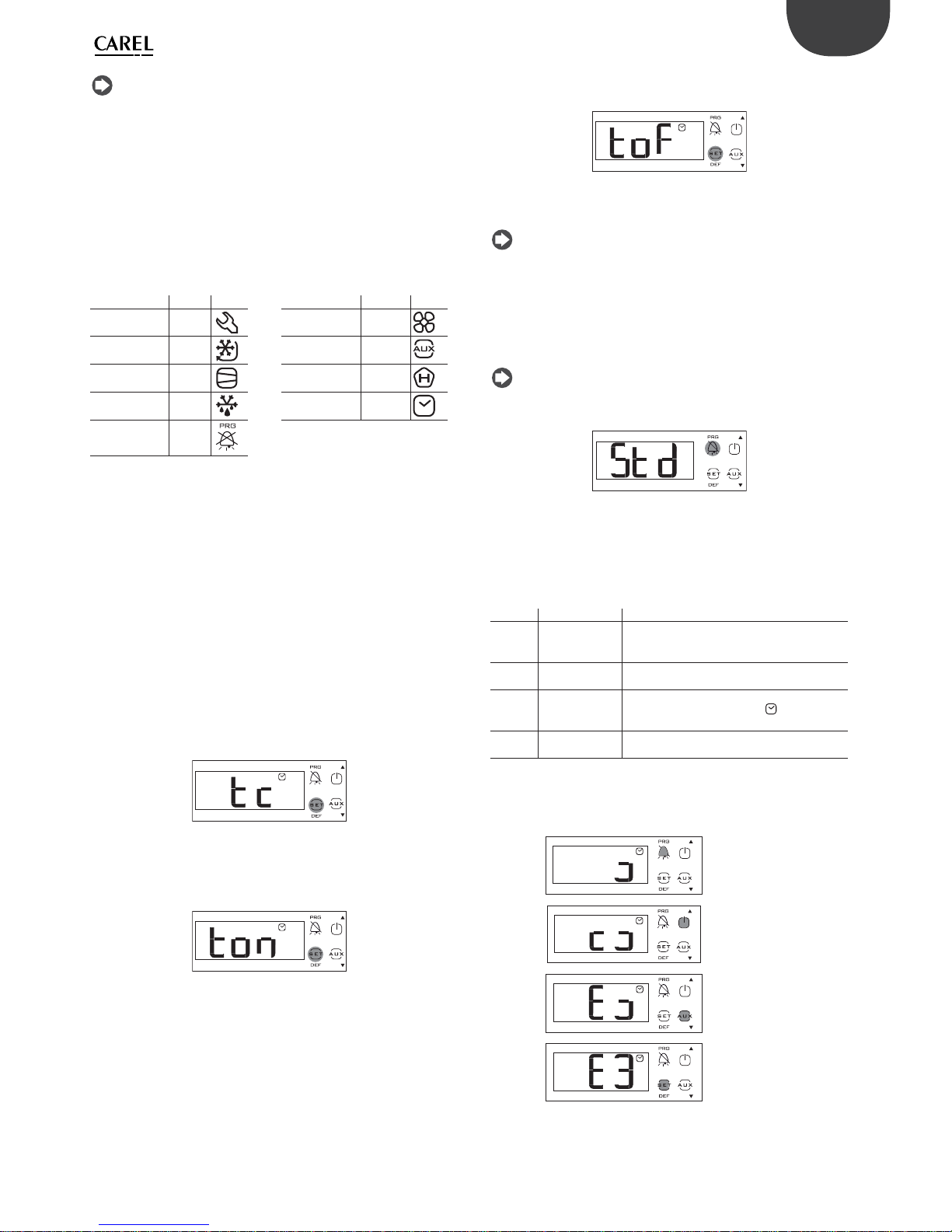
Example 1: setting the current time/date
1. Access the type C parameters as described in the corresponding
paragraph;
2. Press UP/DOWN and select the parent parameter tc, or alternatively
press the PRG button to select the “rtc” parameter category and then
the parameter tc;
3. Press Set: parameter y is displayed, followed by two digits that
indicate the current year;
4. Press Set and set the value of the current year (e.g.: 12=2012), press
Set again to con rm;
5. Press UP to select the next parameter - month, and repeat steps 3
and 4 for the following parameters:
6. M=month, d=day of the month, u=day of the week h=hour,
m=minutes;
7. To return to the list of main parameters, press Prg/mute and then
access parameters ton and toF (see the following paragraph), or
alternatively:
8. To save the settings, press Prg/mute for 5 seconds and exit the
parameter setting procedure.
Example 2: setting the light/auxiliary output (aux) On/O time
1. Access the type C parameters as described in the corresponding
paragraph;
2. Press UP/DOWN and select the parent parameter ton = on time;
3. Press Set: parameter d is displayed , followed by one or two digits that
represent the on day, as follows:
0 = function disabled
1 to 7 = Monday to Sunday
8 = Monday to Friday
9 = Monday to Saturday
10 = Saturday & Sunday
11 = every day;
4. Press Set to con rm and go to the on time parameters h/m=hours/
minutes;

20
ENG
ir33plus +0300028EN rel. 1.1 - 05.05.2017
Defrost
To activate a defrost, the defrost probe must measure a temperature less
than the end defrost temperature (par. dP1).
ACTIVATION: press for 5 seconds:
ir33+
DEF
ir33+ wide / Easy wide
After 5 seconds, the display shows the start defrost signal (dFb) for 3 s.
The controller enters defrost mode, with the corresponding icon shown
on the display, together with the message “dEF” if set accordingly by
parameter d6. The defrost relay is also activated.
Par. Description Def Min Max UoM
d6 Terminal display during defrost0 = Tempera-
ture alternating with dEF1 = Display disabled2
= dEF
102-
Tab. 3.i
Example: defrost activation on ir33+.
DEACTIVATION: press for 5 seconds:
ir33+
DEF
ir33+ wide / Easy wide
After 5 seconds, the display shows the end defrost signal (dFE). The
controller exits defrost mode, returning to the standard display.
Example: defrost deactivation on ir33+.
On/O
To switch the controller o from the keypad:
• press On-O for 3 seconds.
The display shows the text O ashing for 3 seconds, and then on steady.
Finally, the text O alternates with the standard display. Any active output
relays are deactivated.
To switch the controller on from the keypad:
• press On-O for 1 s.
The display shows the text On for 1 s and then returns to the standard
display. Any output relays are activated again.
Continuous cycle
For the explanation of the continuous cycle function, see chapter 6.
To activate the continuous cycle, the value of parameter cc must be >0.
ACTIVATION: press the button
or combination of buttons
for 5 seconds
ir33+
+
ir33+ wide Easy wide
The message “cc” ashes on the display for 3 seconds, and subsequently,
if the conditions are suitable, the controller shows the start continuous
cycle message “ccb” and the corresponding icon on the display.
ir33+ wide,
ir33+ wide small
easy wide, easy
wide small
aux
prg
mute
aux
prg
mute
aux
prg
mute
aux
prg
mute
aux
prg
mute
aux
prg
mute
prg
mute
aux
prg
mute
aux

21
ENG
ir33plus +0300028EN rel. 1.1 - 05.05.2017
Example: continuous cycle activation for ir33+
DEACTIVATION: press the
button or combination of
buttons for 3 s:
ir33+
+
ir33+ wide Easy wide
The message “cc” ashes on the display for 3 seconds, and subsequently
the controller shows the end continuous cycle message, “ccE”.
ir33+
Display defrost probe
To display the value measured by the defrost probe:
• press Set and UP together for 3 s;
• the code of parameter d/1 is displayed ashing;
• continue holding the buttons until the value measured by the defrost
probe is displayed;
• release the buttons;
• the standard display is shown again after 10 s.
ir33+
Auxiliary/light output activation
Activation from the keypad: for automatic activation from scheduler see
the second example in paragraph 3.5. To activate the auxiliary (H1 = 2)
and/or light output (H1 = 3) from the keypad:
• press AUX and/or if present;
• the message AUX ashes on the display for 1 s:
• press and hold until activating the output and the corresponding icon
on the display, which then shows the standard display.
Auxiliary output active
Light output active
Press AUX to deactivate the AUX or light output.
Probe calibration
Parameters /c1 to /c4 are used are used to calibrate the rst, second, third
and fourth temperature probe respectively. Access the parameters and
then set the required values. When pressing Set, after having entered the
value, the display does not show the parameter, but rather immediately
shows the new value of the probe reading being calibrated. This means
the result of the setting can be checked immediately and any adjustments
made as a consequence. Finally, press Prg for 5 seconds to save the value
of the parameter.
HACCP menu
The controller must be tted with the RTC (real time clock).
To enter the HACCP menu:
• press the combination/button shown the table below for 1 s;
• press UP/DOWN to display the parameters in the HACCP category;
• press PRG for 5 seconds to return to the standard display.
ir33+
+
ir33+ wide Easy wide
ir33+
ir33+ wide /
ir33+ small wide
Minimum and maximum temperature monitoring
The controller can record the minimum and maximum temperature
measured by the control probe over a period of up to 999 hours (more
than 41 days).
To enable monitoring:
• enter programming mode as explained in the corresponding
paragraph;
• set r5=1;
• select rt;
press:
ir33+
DEF
ir33+ wide Easy wide
This displays how long minimum and maximum temperature monitoring
has been active, (if recording has just been enabled, rt=0);;
• to restart temperature recording, press for more than 5 s:
ir33+
ir33+ wide Easy wide
The message “rES” indicates that the log has been deleted. The controller
resets the total hours and restarts monitoring;
• press Set to return to the list of parameters;
• to display the maximum temperature measured by the probe, read the
value associated with parameter rH;
• to display the minimum temperature measured by the probe, read the
value associated with parameter rL.
Note: after the maximum time of 999 hours, minimum and
maximum temperature monitoring continues, while the time interval
remains xed at 999.
Important: the values of parameters rt, rL and rH are saved to the
controller’s memory every hour. If the controller is not connected to an
uninterruptible power supply, a temporary blackout may mean the
values of rt, rL and rH measured in the last hour will be lost. When power
returns, the controller automatically restarts monitoring from the
previously saved values.

22
ENG
ir33plus +0300028EN rel. 1.1 - 05.05.2017
4. COMMISSIONING
4.1 Con guration
The con guration parameters are set when commissioning the controller,
and involve:
• date/time setting, if the clock is tted (RTC – real time clock);
• analogue probe measurement stability;
• probe display stability;
• standard display shown on the controller, and on the remote display,
and the decimal point;
• serial address for the supervisor network connection;
• temperature unit of measure (°C / °F);
• lock keypad, disable buttons and buzzer;
• display during the defrost.
Date/time setting
See example 1 in par. 3.5.
Analogue probe measurement stability
De nes the coe cient used to stabilise the temperature measurement,
ltering the reading based on two algorithms:
• limitation of variation: the maximum variation the value is limited, so as
to reduce impulsive disturbance;
• moving average: this limits the e ect of any noise superimposed over
the temperature measurement that may negatively a ect control
performance.
Low values assigned to this parameter allow a prompt response of the
sensor to the temperature variations; the reading however become
more sensitive to disturbance. High values slow down the response, but
guarantee greater immunity to disturbance, that is, a more stable and
more precise reading.
Par. Description Def Min Max UOM
/2 Probe measurement
stability
4 1 15 -
Tab. 4.a
Probe display stability
Important: this parameter only applies to the temperature shown
on the display, and not the reference control temperature.
Par. Description Def Min Max UOM
/3 Probe display stability
0 = Disabled
1 = Fast update…
15 = Slow update
0 0 15 -
Tab. 4.b
This parameter is used to set the rate at which the temperature display
is updated. The temperature shown on the display tends to follow rapid
deviations away from the set point very slowly, and vice-versa, moves very
quickly in the event where the temperature displayed is approaching the
set point. In the table the delay of display based to the setting.
/3 Display delay /3 Display delay
0 Disabled 8 50 s
1 5 s 9 60 s
2 10 s 10 75 s
3 15 s 11 90 s
4 20 s 12 105 s
5 25 s 13 120 s
6 30 s 14 150 s
7 40 s 15 180 s
Tab. 4.c
If the control temperature exceeds the high or low temperature
thresholds and a high/low temperature alarm (AH/AL) is activated, or if
the maximum number of ltering steps is exceeded, the ltering would
immediately be bypassed and the temperature displayed would be the
temperature e ectively measured, until all the alarms are reset.
Example: in the case of bottle coolers, typically used in supermarkets
where the doors are opened frequently, due to the greater thermal
inertia of the liquids compared to the air (and the fact that the probe
is positioned in the air and not directly on the products), the controller
measures a temperature that is higher than e ective temperature of the
soft drinks, thus displaying an “unrealistic” temperature. Setting parameter
/3 to a value other than 0, any abrupt variations in temperature are
“ ltered” on the display, showing a temperature trend that is “closer” to
the actual trend of product temperature.
Display on user terminal and remote display
The user terminal (controller display) can either display the value of the
virtual control probe (see the chapter on control), the reading of probes
1-4 or the set point. Similar displays can be selected on the remote
display, except for the set point.
Par. Description Def Min Max UOM
/tI Display on user terminal
1 Virtual probe 5 Probe 4
2 Probe 1 6 Reserved
3 Probe 2 7 Set point
4 Probe 3
117-
/tE Reading on remote display
0 Terminal not tted 4 Probe 3
1 Virtual probe 5 Probe 4
2 Probe 1 6 Reserved
3 Probe 2
006-
Tab. 4.d
Serial address (parameter H0)
H0 assigns the controller an address for the serial connection to a
supervisory and/or telemaintenance system.
Par. Description Def Min Max UOM
H0 Serial address
1 0 207 -
Tab. 4.e
Temperature unit of measure and decimal point display
The following settings are available:
• choose the temperature unit of measure, between degrees Celsius (°C)
and Fahrenheit (°F);
• enable/disable the decimal point on the display and the buzzer.
Par. Description Def Min Max UOM
/5 Temperature unit of measure
0 =°C, 1 =°F
001-
/6 Display decimal point
0/1 = yes/no
001-
H4 Buzzer
0/1=enabled/disabled
001-
Tab. 4.f
Lock keypad and disable buttons
Certain functions regarding the use of the keypad can be disabled, for
example parameter and set point settings if the controller is accessible
to the public. In addition, an individual button or group of buttons can
be disabled.
Par. Description Def Min Max UOM
H2
Disable keypad functions
106-
H6
Terminal keypad lock con guration
0 = all buttons enabled
0 0 255 -
Tab. 4.g
Functions that can be disabled on the keypad
Important: if setting H2 ≠ 1, 3, the type F parameters cannot be set,
but rather only their values can be displayed. Type C parameters, being
password-protected, can always be set on the keypad following the
procedure described in chap. 3. If “set point” and “F parameter” setting is
disabled, the set point and the type F parameters cannot be set, but
rather only their values can be displayed.
Note: Y = can be activated / enabled; N = cannot be activated /
enabled

23
ENG
ir33plus +0300028EN rel. 1.1 - 05.05.2017
ir33+, ir33+ wide, easy wide
par. H2
FUNCTION 0123456
LIGHT Y Y Y Y Y Y Y
AUX YYYYYYY
ON/OFF Y Y Y Y N N Y
HACCP YYYYYYY
PRG/MUTE (mute) Y Y Y Y Y Y Y
UP+DOWN (continuous cycle) Y Y Y Y N N N
SET/DEF (defrost) Y Y Y Y N N N
SET (set point) setting N Y N Y Y N N
“F” parameter setting N Y N Y N N N
Tab. 4.h
Disable buttons
Using the individual bits, the functions relating to the buttons on the
keypad can be enabled or disabled, according to the relationships shown
in the table below: to calculate the value to be assigned to parameter H6,
simply sum the values assigned to the functions that should be disabled.
Note: the functions disabled using parameter H6 are added to
those disabled using parameter H2.
Disable buttons
Bit Value
par. H6
ir33+
button
ir33+ function ir33+wide
button
easy wide
button
Description
01
Display defrost
temp. procedure; access
HACCP; defrost
Display defrost
temp. procedure
12
Activate AUX
output 1, continuous cycle
Defrost
24
Up, On-O Continuous
cycle
38
Mute alarms Mute alarms
416 - -
Access HACCP
532 - -
Activate/
deactivate aux
output 1
664 - -
On/O
7 128 - -
Activate/
deactivate aux
output 2, light
Tab. 4.i
4.2 Loading the sets of parameters
Up to 6 sets of custom parameters can be selected on the controller, after
having been loaded using the VPM programming tool (Visual Parameter
Manager, see appendix 1) and the programming key.
Procedure:
• power down the controller;
• power up while holding Prg/mute;
• the display will show the rst set: bn0;
• press UP/DOWN to select set bn1 to bn6. For example, select bn2;
• press Set to con rm the selected set: the controller will load the set
of parameters called bn2 and then will return to the standard display.
Par. Description Def Min Max UOM
Hdn Number of default parameter sets available 0 0 6 -
Tab. 4.j
Note: bn0 is the default set of parameters on the controller, i.e. the
default con guration. When one of sets bn1 to bn6 is loaded, bn0 is
overwritten with the new set and is consequently erased.
4.3 Preparing for operation
Once having completed the installation, con guration and programming
procedures, before starting the controller, check that:
• the wiring has been completed correctly;
• the programming logic is suitable for controlling the unit and the
system being managed;
• if the controller is tted with RTC (clock), set the current time and date,
and the on and o times for the light/auxiliary output;
• set the standard display;
• set the “probe type” parameter based on the probe available and the
type of control (NTC, NTC-HT, PTC); note that the controllers that use
PTC probes may have di erent part numbers from those that only use
NTC probes;
• set the type of defrost: heater or hot gas;
• set the temperature unit of measure (°C or °F);
• the protection functions (delay at start-up, rotation, minimum on and
o times for the outputs) are active.
Note: all the alarms with manual reset can be reset by pressing the
Prg and UP buttons together for more than 5 seconds. See the chapter on
“Alarms”.
24
ENG
ir33plus +0300028EN rel. 1.1 - 05.05.2017
5. FUNCTIONS
5.1 Probes (analogue inputs)
The ir33+ platform controllers feature a maximum of 4 analogue inputs,
which are used for NTC, high temperature NTC (NTC Enhanced Range)
or PTC temperature sensors (see the note below). Probes S3 and S4 can
also be con gured as digital inputs. Probe S1 is the control probe and its
function cannot be changed; the functions of probes S2, S3, S4 can be
selected using parameters /A2, /A3, /A4. The probes can be calibrated
to adjust their readings. In particular, parameters /c1 to /c4 are used to
increase or decrease the values read by the probes connected to inputs
S1, S2, S3 and S4 across the entire the range of measurement. For the
calibration procedure, see paragraph 3.5.
Par. Description Def Min Max UOM
/P Type of probe
0 = NTC Standard Range -50T90°C
1 = NTC Enhanced Range -40T150°C
2 = PTC Standard Range -50T150°C
002-
/c1 Probe 1 calibration 0 -20 20 /c2 Probe 2 calibration 0 -20 20 /c3 Probe 3 calibration 0 -20 20 /c4 Probe 4 calibration 0 -20 20 -
Tab. 5.a
A
T1
T2
min max
Fig. 5.a
Key
T1 Temperature read by the probe
T2 Value calibrated by T1
A Calibration value
min, max Range of measurement
Note: the controllers that use PTC probes may have di erent part
numbers from those that only use NTC probes.
Example:
Model P/N Probes available
ir33+ IREV*7******* NTC/PTC
ir33+ wide PBEV*6******* PTC
easy wide
Tab. 5.b
Assigning the functions of probes S2, S3, S4
The controller, inside the refrigerated cabinet or cold room, can use the
following probes:
• defrost, located on the evaporator, preferably where ice remains the
longest;
• condenser, used to protect the compressor against high pressure
when the condenser is o or the condenser fan is malfunctioning;
• frost protection, to activate the corresponding alarm.
Note:
• to con gure probes 3 and 4 as digital input 1 and 2 respectively, set
parameters /A3 e /A4 =0;
• if multiple probes have been con gured with the same operating
mode, the controller will use the rst probe in increasing order with
that con guration.
Par. Description Def Min Max UOM
/A2 Probe 2 con guration (S2) (M models) 0 0 4 /A2 Probe 2 con guration (S2)
0 Absent
1 Product (display only)
2 Defrost
3 Condenser
4 Frost
204-
/A3 Probe 3 con guration (S3)
0 Digital input 1 (DI1)
1 Product (display only)
2 Defrost
3 Condenser
4 Frost
003-
/A4 Probe 4 con guration (S4/ DI2)
0 Digital input 2 (DI2)
1 Product (display only)
2 Defrost
3 Condenser
4 Frost
004-
Tab. 5.c
5.2 Digital inputs
Digital inputs DI1 and DI2 respectively can be enabled in the place of
probes S3 and S4. Digital inputs 1, 2 must rst be enabled (par. /A3 and /
A4 = 0) and then assigned to a speci c function (par. A4 and A5). Finally,
an external contact can be connected to the multifunction input to
activate various types of functions, such as alarms, curtain/door switches,
start defrost, etc. See the table below.
Important: to ensure unit safety in the event of serious alarms, the
unit must be tted with all the electromechanical safety devices needed
to guarantee correct operation..
Note: (applies to all settings of par. A4 and A5): if 2 digital inputs are
con gured in the same way, for example to enable defrost, the disable
event is generated when at least one of the inputs is open, while the
enable event is generated when at both inputs are closed.
Digital input functions
PARAMETERS A4, A5
Setting Contact
OPEN CLOSED
0 = not active - 1 = immediate external alarm active not active
2 = delayed external alarm active not active
3 = select probe (ir33M) see /tI rst probe
enabled (/A2,
/A3, /A4, /A5)
3 = enable defrost (all other models) not enabled enabled
4 = start defrost not active active
5 = door switch with compressor and evapo-
rator fans o
door open door closed
6 = remote ON/OFF OFF ON
7 = curtain switch curtain open curtain closed
8 = low pressure switch low pressure
status
normal status
9 = door switch with fans o door open door closed
10 = direct/reverse operation direct mode reverse mode
11 = light sensor light o light on
12 = activate aux output deactivated activated
13 = door switch with compressor and fans
o and light not managed
door open door closed
14 = door switch with fans o and light not
managed
door open door closed
Tab. 5.d

25
ENG
ir33plus +0300028EN rel. 1.1 - 05.05.2017
The following parameters are involved in the explanation of the settings
for A4 and A5.
Par. Description Def Min Max UOM
A4 Multifunction digital input 1 con guration
(DI1)
See the previous table
0/3
(IR33M)
014-
A5 Multifunction digital input 2 con guration
(DI2)
See the previous table
0 0 14 -
A6 Stop compressor on external alarm
0 = compressor always o ;
100 = compressor always on
0 0 100 min
A7 Digital alarm input delay0 = control
outputs unchanged
0 0 250 min
Ado Light management with door switch 0 0 1 c7 Maximum pump down time (PD)
0 = Pump down disabled
0 0 900 s
d5 Defrost delay at start-up (if d4=1) or from DI0 0 250 min
d8 High temperature alarm bypass time after
defrost (and door open)
1 0 250 hr/
min
d8d Alarm bypass time after door open 0 0 250 min
dI Maximum time between consecutive
defrosts - 0 = defrost not performed
8 0 250 hr/
min
Tab. 5.e
1 = Immediate external alarm
Application: external alarm that requires immediate action (for example
high pressure alarm or compressor thermal overload). When the alarm is
activated:
1. the following actions occur:
• a signal is shown on the display (‘IA’);
• the icon ashes;
• the buzzer is activated, if enabled;
• the alarm relay is activated, if selected;
2. and the actuators behave as follows:
• compressor: operates depending on the values assigned to
parameter ‘A6’ (stop compressor on external alarm).
• fans: continue operating according to the fan parameters (“F”).
Note when the compressor stops, the minimum compressor on
time (“c3”) is ignored.
2 = Delayed external alarm
The delayed external alarm is equivalent to the immediate external alarm,
however with the addition of a delay A7 before the signal (“dA”).
Application: this con guration is especially useful for managing the low
pressure alarm. In fact, when starting for the rst time, the unit often
detects a low pressure alarm due to the environmental conditions rather
than a unit malfunction. Setting a delay for the alarm (par. A7) will avoid
false signals. In fact, by suitably calculating the delay, if the low pressure
is due to environmental conditions (low temperature), the alarm will be
automatically reset before the delay has elapsed.
Note if “A7”=0 activation of the alarm does not cause the compressor
to operate according to the values assigned to parameter ‘A6’ (stop
compressor on external alarm); on the other hand, the “dA” signal is
displayed, the icon
ashes, the buzzer and the alarm relay (if selected)
are activated; the delayed external alarm is thus signal-only.
3 = Probe shown on the display (IR33M models)
On thermometer-only models, this setting selection is used to exploit
the digital input in order to show, on the display, the probe selected by
parameter “/tI” or the rst enabled probe (see parameters “/A2”,”/A3”,”/A4”).
In practice, if the contact is open, the probe selected by parameter “/tI” is
shown, whereas, if the contact is closed, the rst enabled probe is shown.
Note: if more than one digital input is con gured as the probe
selection, the probe selected by parameter /tI is displayed when at least
one of the inputs is open.
3 = Enable defrost (all other models)
Application: any defrosts called when the contact is open remain pending
until the contact closes. The various possibilities are shown below.
A4 = 3
Contact Defrost
Open Not enabled
Closed Enabled
Closed without
request from the
controller
Not performed
Closed with in
progress
When the digital input opens, the defrost is immediately stopped and the unit restarts normal operation
(without performing the dripping or post-dripping
stages). The
LED starts ashing to indicate that the
defrost call is pending, awaiting the next enabling
signal (closing of the contact), when the defrost will
be performed completely.
Tab. 5.f
Note this function is useful to prevent defrosts on units accessible to
the public during opening times.
4 = Start defrost from external contact
Application: this function is useful for performing defrosts in real time. To
perform the defrosts, connect a cyclical, mechanical or electronic timer
to the selected digital input: a series of units can be connected to the
same timer, setting di erent values for parameter d5 (defrost delay from
multifunction input) to avoid simultaneous defrosts.
Important: for 12 Vac and 12/24 Vac versions. When connecting a
series of units to the same timer, the best solution is to insulate all the
contacts galvanically, inserting an intermediate relay for each contact.
ON
OFF
ON
OF
F
OFF
t
TIMER
OFF
dP(2)dP(1)
d5(2)
DEFROST
UNIT 1
UNIT 2
UNIT 3
DEFROST
O
N
ON
OFF
ON
DEFROST
dP(3)
d5(1)=0
d5(3)
Fig. 5.b
Key
dP Maximum defrost duration d5 Defrost delay from
digital input
UNIT 1…3 Unit 1-3 t Time
5 = Door switch with compressor and evaporator fan o
Parameter d8 de nes the high temperature alarm bypass time after the
defrost ends (or the door is opened).
Parameter d8d is the alarm bypass time after the door is opened. If d8d=0,
the alarm delay after door open coincides with the value of parameter d8.
Setting “A4”=5 manages the cold room door switch. The behaviour of the
door switch depends on the status of the light when the door is opened:
1. light o ;
2. light on.

26
ENG
ir33plus +0300028EN rel. 1.1 - 05.05.2017
Case 1: light o when opening the door
If the door is opened with the light OFF:
• the compressor and the evaporator fans are switched o ;
• the light is switched on (only on models tted with at least 1 auxiliary
relay programmed as a light output);
• the reading displayed and the icon ash;
• the temperature alarms are disabled.
If the door remains open for a time longer than “d8” (d8d), the controller
resumes normal operation:
• the compressor and the evaporator fan are switched on, if needed;
• the light is switched o ;
• the reading on the display ashes;
• the buzzer and the alarm relay are activated;
• the temperature alarms are enabled with the delay “Ad”.
To stop the reading from ashing, close the door. When the door closes,
the controller resumes normal operation, switching o the light and
enabling the temperature alarm after the delay time “d8”. The compressor
is re-started, after any set protection times (see the “C” parameters).
Case 2: light on when opening the door
The
icon is on. If the door is open with the light on, it is assumed the
user enters the cold room, turning on the light before entering, closing
the door behind him, and then exits the room, closing the door a second
time.
When the door is opened the rst time:
• the compressor and the evaporator fans are switched o ;
• the light stays on (only on models tted with at least 1 auxiliary relay
programmed as a light output);
• the reading is displayed and the icon ashes;
• the temperature alarms are disabled.
When the door is closed the rst time, the controller maintains the
previous situation:
• the compressor and the evaporator fans stay o ;
• the light stays on;
• the reading is displayed and the icon ashes;
• the temperature alarms are disabled.
Door opened the second time: no change.
When the door is closed the second time, the controller resumes
normal operation, switching o the light and enabling the temperature
alarm after the delay time “d8”. When the compressor re-starts, any set
protection times must elapse rst (see the “C” parameters).
If, after opening, the door remains open for a time longer than “d8” or
“d8d”, the controller resumes normal operation:
• compressor and evaporator fan switched on if needed;
• light o ;
• the reading on the display ashes;
• the buzzer and the alarm relay are activated;
• the temperature alarms are enabled with the delay “Ad”;
• when the door closes, the high temperature alarm bypass time after
door open d8 is not set.
To stop the reading from ashing, close the door.
If, after being closed for the rst time, the door remains closed for longer
than time “d8” or “d8d”, the controller resumes normal operation:
• compressor and evaporator fan switched on if needed;
• light o ;
• the temperature alarms are enabled with the delay “d8”;
• the high temperature alarm bypass time after door open d8 is set.
If, after the door is closed for the rst time, the light is switched o
manually, the controller resumes normal operation:
• compressor and evaporator fan switched on if needed;
• light o ;
• the temperature alarms are enabled with the delay “d8”;
• the high temperature alarm bypass time after door open d8 is set.
Note:
• if the light was previously switched on manually, when the door is
closed for the second time, it is automatically switched o ;
• even if the evaporator fan is managed by the “fan controller” (see the F
parameters), the fans are forced to stop when the door is open.
This algorithm resolves any problems relating to faults or malfunctions of
the door switch.
Door-switch
Fig. 5.c
Note: if more than one digital input is con gured as a door switch,
the door is considered open when at least one of the inputs is open.
6 = Remote On/O
The digital input may be programmed also as remote ON/OFF. When the
control is in OFF:
• the temperature is displayed alternating with the message “OFF”;
• the internal timer for parameter “dI” is updated. If “dI” expires when the
unit is OFF, a defrost is performed when the unit is switched on again;
• the auxiliary relay set as auxiliary and light output is active, the other
auxiliary outputs are o ;
• the buzzer and the alarm relay are deactivated;
• the controller does not perform the control functions, defrosts,
continuous cycle, signal temperature alarms and all other functions;
• the compressor protection times are observed;
When the controller is switched back on, all the functions are re-activated,
with the exception of:
• defrost on start-up;
• compressor and fan delay at power on.
Note: the ON/OFF from external digital input has priority over the
keypad and the supervisor;
7 = Curtain switch
If the input is selected as a curtain switch, the controller modi es the
set point when the contact closes, adding the value of parameter “r4”;
the new value is then used for all the functions relating to the set point
(e.g. relative high and low temperature alarms, control with dead band,
control with two compressor steps etc.). For example when “r4”=3.0
(default value), the set point is increased by 3 degrees from the value
used when the curtain is open.
Par. Description Def Min Max UOM
r4 Automatic night-time set point variation 3 -20 20 °C/°F
Tab. 5.g
St
Sv
rd
OFF
ON
DI OPEN
CMP/FAN
St
Sv
r4
OFF
ON
DI CLOSED
rd
CMP/FAN
Fig. 5.d

27
ENG
ir33plus +0300028EN rel. 1.1 - 05.05.2017
Key
St Set point rd Di erential
CMP Compressor FAN Fan
Sv Virtual probe r4 Automatic night-time set point variation
Note: if one of the auxiliary outputs is used to manage the light,
lowering the curtain automatically switches the light o , while raising it
switches the light on.
8 = Low pressure switch input for pump down
See par. 6.4. Setting “A4”=8 manages the low pressure switch. The low
pressure alarm “LP” is signalled when the low pressure switch is activated:
• during normal control (c7=0) with the compressor on, or alternatively
• with pump-down function con gured (c7 >0), if the pump down valve
is open and the compressor is on.
The low pressure alarm signal is delayed by the time set for parameter
“A7”. The low pressure alarm “LP” stops the compressor.
ir33+
ON
OFF
ON
OFF
t
CMP
LOW
Pressure
switch
Pump down
valve
HIGH
OFF
ON
LP
Alarm
A7
Fig. 5.e
Key
CMP Compressor Pump down valve Pump down valve
Pressure Switch Pressure
switch
LP alarm Low pressure alarm
t Time A7 Alarm signal delay
Note: this parameter, together with c7, c8, c9 and H1, H5, allows
management of the “pump-down” algorithm (see par 6.3).
9 = Door switch with fan o only
Same as for option “A4”=5, with the di erence being that when opening
the door only the evaporator fan is switched o .
10 = Direct/reverse operation
Important: when A4 = 10, the status of digital input has priority
over the setting of parameter r3 (direct/reverse operating mode).
When the contact is open, the controller operates in “direct” mode
(cooling), when the contact is closed, in “reverse” mode (heating). A switch
can therefore be connected to select heating or cooling operation.
St
Sv
rd
OFF
ON
DI OPEN
CMP/FAN
r3 = 0, 1, 2
DIRECT
Sv
rd
OFF
ON
DI CLOSED
CMP/FAN
r3 = 0, 1, 2
REVERSE
St
Fig. 5.f
Key
St Set point Sv Virtual probe
rd Di erential CMP Compressor
FAN F an
11 = Light sensor
The digital input is used to read a light sensor (P/N PSOPZLHT00, actually an
analogue input, from which a digital signal is taken using the parameter or
threshold of the light sensor).
The light sensor can be located:
• in the door jamb (ref. A);
• inside the cold room or cabinet (ref. B).
Par. Description Def Min Max UOM
AF Light sensor OFF time
0 Sensor in the door jamb
> 0 Sensor inside the cold room or cabinet
0 0 250 s
Tab. 5.h
B
A
Fig. 5.g
A (AF=0) B (AF = 1)
Light sensor
signal
The sensor signals
the opening and
closing of the door
The sensor signals the opening of the
door and detects light inside the cabinet/cold room. The sensor also signals
closing of the door
Inside light: on With the door open If the sensor detects light
Inside light: o With the door
closed, minimum o
time of 5 s, to avoid
rapid, successive
impulses of the light
relay
Closing of the door is measured by
time, as the inside light will illuminate
the sensor. After the time AF (>0) the
inside light is switched o for 5 secon-
ds. If the light sensor signals darkness,
the door must be closed and the light
will therefore remain o ;
if it signals light: the door is open and
the light will be switched on again.
Tab. 5.i

28
ENG
ir33plus +0300028EN rel. 1.1 - 05.05.2017
12 = Auxiliary output
Set H1 and/or H5 = 2 to activate the auxiliary output.
See the table at the start of this paragraph for details on the activation/
deactivation logic.
13 = Door switch with compressor and fan o , light not managed
Operation is similar to A4=5, with the di erence that the light output is
not modi ed.
Note: the light management algorithm depends on parameter Ado
– “Light management with door switch” (masked parameter accessible
from VPM).
Ado Light when ope-
ning the door
Algorithm Description
0o normal open-close
on extended open-close-open-close
1o extended open-close-open-close
on normal open-close
Tab. 5.j
If the digital input is selected to not manage the light (A4, A5, A9 =13 or
14), the algorithm is modi ed as follows:
Ado Light when ope-
ning the door
Algorithm Description
0o normal open-close
on extended open-close-open-close
1o normal open-close
on normal open-close
Tab. 5.k
See the table at the start of this paragraph for details on the activation/
deactivation logic.
14 = Door switch with fan o only, light not managed
Operation is similar to A4=9, with the di erence that the light output is
not modi ed.
Note: the light management algorithm depends on parameter Ado,
as shown in the previous table.
See the table at the start of this paragraph for details on the activation/
deactivation logic.
5.3 Digital outputs
The parameters in question concern the minimum on or o times of the
same output or di erent outputs, so as to protect the loads and avoid
swings in control.
Important: for the times set to become immediately operational,
the controller needs to be switched o and on again. Otherwise, the
timers will become operational when the controller is next used, when
the internal timer is set.
Relay output protectors (parameters c7,c8,c9)
Par. Description Def Min Max UOM
c0 Compressor, fan and AUX start delay at power on0 0 15 min
c1 Minimum time between successive compres-
sor starts
0 0 15 min
c2 Minimum compressor o time 0 0 15 min
c3 Minimum compressor on time 0 0 15 min
Tab. 5.l
• c0: when the controller is powered on, the compressor, evaporator
fans and auxiliary relay in neutral zone control (‘H1’=11 or ‘H5’=11)
are started after a delay (in minutes) equal to the value assigned to
this parameter. The delay is used to protect the compressor against
repeated starts in the event of frequent power failures;
• c1 de nes the minimum time between two consecutive starts of the
compressor;
• c2 de nes the minimum compressor o time;
• c3 de nes the minimum compressor on time;
Other relay output protectors (parameter c11)
Par. Description Def Min Max UOM
c11 Second compressor start delay 4 0 250 s
Tab. 5.m
• c11 de nes the activation delay between the rst and second
compressor (or between the rst and the second compressor step).
c1
ON
OFF
ON
OFF
t
STEP1
STEP2
c3 c2
c11
c0
POWER_ON
Fig. 5.h
Key
Step1 Compressor step 1
Step2 Compressor step 2
t time
Functions assigned to AUX1/AUX2
Outputs AUX1 and AUX2 can be assigned di erent functions, such as
alarm signal, auxiliary output, light output, pump down valve, condenser
fan, reverse output with neutral zone, second compressor, second
compressor with rotation. For details, see the chapter on control.
Par. Description Def Min Max UOM
H1 AUX1 output con guration 1 0 13 -
0 = normally energised alarm
1 = normally de-energised alarm
2 = auxiliary
3 = light
4 = auxiliary evaporator defrost
5 = pump down valve
6 = condenser fan
7 = delayed compressor
8 = auxiliary with deactivation when OFF
9 = light with deactivation when OFF
10 = no function
11 = reverse with neutral zone
12 = second compressor step
13 = second compressor step with rotation
H5 AUX2 output con guration
See H1
3 0 13 -
Tab. 5.n

29
ENG
ir33plus +0300028EN rel. 1.1 - 05.05.2017
6. CONTROL
6.1 Switching the controller On/O
The controller can be switched ON/OFF from a number of sources;
keypad, supervisor and digital input. In this operating mode, the display
will be show the temperature selected for parameter /tI, alternating with
“OFF”. The digital input can be used to switch the controller on/o , setting
parameter A4/A5 to “6”. Switching on/o from digital input has priority
over the same function from the supervisor and the keypad.
Source Priority Note
Digital input 1 Disable On/O from keypad and supervisor
Keypad 2
Supervisor 3
Tab. 6.a
6.2 Virtual probe
The control output is the compressor output, which in most cases is also
associated with the evaporator fan output. The control probe is probe S1,
while probes S2, S3, S4 can be assigned functions such as product probe
(display only), defrost probe, condenser probe or frost protection probe.
For vertical display cases, the virtual probe (Sv) should be de ned as the
control probe; this represents the half-way point between the display
case outlet and intake probes, and the reading is thus a ected by the
environmental conditions. During the day, the display case light is on and
the curtain is open to allow customers to take out the products store, at
night the curtain is closed and the light is o . Due to the lower heat load
at night, the night-time set point is increased by the value of parameter
r4.
Par. Description Def Min Max UOM
St Set point 0 r1 r2 °C/°F
r4 Automatic night-time set point variation 3.0 -20 20 °C/°F
/4 Virtual probe composition
0 = control probe S1
100 = probe S2
0 0 100 -
Tab. 6.b
Parameter /4 is used to determine the virtual probe (Sv) as the weighted
average of control probe S1 and probe S2, according to the following
formula:
Sv =
[ S1*(100 - /4) + S2*/4
100
DAY: set point = -13°C
S1
S2
NIGHT: set point = -10°C
S1
S2
Sv=(S1+S2)/
2
/4=50
Fig. 6.a
Key
S1 Outlet probe
Sv Virtual probe
S2 Intake probe
6.3 Set point
The reference output is the compressor output (CMP).
The controller can operate in 3 di erent modes, as selected by parameter
r3:
• direct with defrost control;
• direct;
• reverse.
Par. Description Def Min Max UOM
St Set point 0 r1 r2 °C/°F
rd Di erential 2.0 0.1 20 °C/°F
rn Neutral zone 4.0 0.0 60 °C/°F
rr Reverse di erential 2.0 0.1 20 °C/°F
r1 Minimum set point -50 -50 r2 °C/°F
r2 Maximum set point 60 r1 200 °C/°F
r3 Operating mode
0 = Direct with defrost control (cooling)
1 = Direct (cooling)
2 = Reverse (heating)
002-
Tab. 6.c
ON
OFF
Sv
CMP
REVERSE
St
rd
ON
OFF
Sv
CMP
St
rd
DIRECT
Fig. 6.b
Key
St Set point rd Di erential
Sv Virtual probe CMP Compressor
If the second compressor output is activated (H1, H5 = 12) on the AUX
output, the compressor output is activated at St±rd/2 and the AUX
output at St±rd, as illustrated in the following gure.
ON
OFF
CMP
ON
OFF
Sv
rd/2
AUX
rd/2
REVERSE
St
ON
OFF
St
Sv
rd/2
CMP
ON
OFF
rd/2
AUX
DIRECT
Fig. 6.c
Key
St Set point rd Di erential
Sv Virtual probe AUX Auxiliary output
CMP Compressor
The neutral zone is activated on the controller only if the reverse output
is activated with neutral zone control, H1 = 11. The gure below shows
direct operation (r3 =0, 1), with 1 compressor output (CMP) and 2
compressor outputs (CMP and AUX2).

30
ENG
ir33plus +0300028EN rel. 1.1 - 05.05.2017
r3=0,1
ON
OFF
CMP
rr rn/2 rn/2
AUX
rd
St
Fig. 6.d
r3=0,1
ON
OFF
CMP
rr rn/2
AUX
rd/2 rd/2
AUX2
St
Fig. 6.e
Reverse operation (r3 =2), with 1 compressor output (CMP) and 2
compressor outputs (CMP and AUX2).
r3=2
ON
OFF
CMP
rn/2
rd
AUX
rn/2rr
Sv
St
Fig. 6.f
r3=2
ON
OFF
CMP
rn/2
rd/2
AUX
rn/2
rr
Sv
AUX2
rd/2
St
Fig. 6.g
Key
St Set point rd Di erential
rn Neutral zone rr Reverse di erential
6.4 Pump down
The pump down function has the purpose completely emptying the
evaporator of refrigerant on reaching the set point. The controller rst
deactivates the pump down valve and then, after a certain time, the
compressor. The application diagram shows the pump down valve and
the low pressure switch. When the controller restarts the compressor,
if protection times c1 and c2 have elapsed, the pump down valve is
opened, and after the time c8 the compressor is activated. The parameters
involved are listed below.
Par. Description Def Min Max
UOM
c7 Maximum pump down time (PD)
0 = pump down disabled
0 0 900 s
c8 Compress. start delay after opening PD valve 5 0 60 s
c9 Autostart in pump down 001-
0 = Disabled
1 = Pump down whenever closing pump down
valve & following low pressure switch activation
with no cooling demand
c10 Pump down by time or pressure
0/1 = pressure/time
001-
Tab. 6.d
Note: c8 is a masked parameter, and can be made visible using the
VPM tool.
C
L
PDV
M
CMP
E
T
V2
P
ir33+
S
F
Fig. 6.h
Key
CMP Compressor P Low pressure switch
C Condenser F Filter-drier
L Liquid receiver E Evaporator
V2 Thermostatic expansion valve S Liquid gauge
PDV Pump down valve
Pump down can be selected:
• by pressure (pressure switch required): when the pump down valve
closes, the compressor continues operating until the pressure switch
measures the de ned low pressure value. The compressor is then
stopped. If the pressure switch does not measure the de ned value
before c7 elapses, the “Pd” alarm - pump down ended by timeout - is
activated;
• by time (pressure switch optional): when the valve closes, the
compressor continues operating for the time c7 or until reaching the
low pressure value. The “Pd” alarm - pump down ended by timeout - is
not activated.
c10 = 0: Pump down by pressure
Pressure switch activated before c7 Pressure switch activated after c7
ON
OFF
ON
OFF
t
CMP,
FAN
VPD
c7
PRESSURE
SWITCH
St
ON
OFF
ALARM
Pd
ON
OFF
Sv
c7
Fig. 6.i
Key
CMP, FAN Compressor, fan c7 Maximum pump down time
VPD Pump down valve Pd Pump down alarm
Pressure switch Pressure switch t Time
Sv Virtual probe

31
ENG
ir33plus +0300028EN rel. 1.1 - 05.05.2017
6.5 Autostart in pump down
As seen in the previous paragraph, on reaching the set point, the
controller closes the pump down valve and then the pressure switch
signals low pressure. If, due to valve tightness problems, the pressure
switch is activated again, the compressor can be restarted by the
Autostart function.
Par. Description Def Min Max UOM
c9 Autostart in pump down
0 = Disabled
1 = Pump down whenever closing pump
down valve & following low pressure switch
activation with no cooling demand
001-
Tab. 6.e
ON
OFF
ON
OFF
t
CMP,
FAN
VPD
c7
PRESSURE
SWITCH
St
ON
OFF
AtS
ON
OFF
Sv
c7
Fig. 6.j
Key
CMP, FAN Compressor, fan St Set point
VPD Pump down valve c7 Maximum pump down time
Pressure switch Pressure switch t Time
Sv Control probe AtS Autostart in pump down
Note:
• in the compressor autostart function, the protection times c1 and c2
are applied, but not c3;
• The message “AtS” is reset automatically when the next pump down
cycle terminates correctly.
Important: in the event of “Pd” alarms, the autostart function is
deactivated.
6.6 Continuous cycle
For information on activating the continuous cycle from the keypad, see
chapter 3. The value of parameter cc must be >0. During operation in
continuous cycle, the compressor continues to operate, independently
of the controller, for the time cc, so as to lower the temperature even
below the set point. The continuous cycle is stopped after the time “cc”
or when reaching the minimum speci ed temperature, corresponding to
the minimum temperature alarm threshold (“AL”). If, after the end of the
continuous cycle, the temperature falls by inertia below the minimum
temperature threshold, the low temperature alarm signal can be ignored
by suitably setting parameter c6: alarm bypass after continuous cycle.
Par. Description Def Min Max UOM
cc Continuous cycle duration 0 0 15 hour
c6 Low temperature alarm bypass time after
continuous cycle
2 0 250 hr/
min
Tab. 6.f
6.7 Anti-sweat heater
When the unit is powered on, the compressor is activated in cooling
mode and the AUX and light outputs are disabled until the control probe
measures a value less than St + Hdh. The aim is to prevent the light or the
heater connected to the AUX output from adding heat and contrasting
the work done by the compressor. When the function is active, the display
shows the corresponding icon, ashing.
Par. Description Def Min Max UOM
Hdh Anti-sweat heater o set
0 = anti-sweat heater function disabled (°C)
32 = anti-sweat heater function disabled (°F)
0 -50 200 °C/°F
Tab. 6.g
The following example refers to the con guration where Hdh = 2 and St
= 0, with activation of the auxiliary output (H1 = 2)
CMP,
FA N
St+ Hdh
AUX,
LIGHT
ON
OFF
Sv
ON
OFF
t
Fig. 6.k
Key
CMP, FAN Compressor, fan LIGHT Light
AUX Auxiliary output Sv Virtual probe
St Set point Hdh O set
t Time
ir33+
Note:
• when alarms “HI”, “IA”, “dA”, “CHt”, “EE”, “EF” ,”rE” are active of the controller
is OFF, the anti-sweat heater function is still enabled;
• at the end of the anti-sweat heater function, the outputs con gured
as light or auxiliary can be controlled by the user from the keypad,
supervisor or digital inputs.
• if AUX1 or AUX2 is con gured as a light or auxiliary output at power on,
the output retains the same status as when previously powered down.
If the anti-sweat heater function is activated, this is no longer true: the
output at power on remains OFF while the function is active. When
the control temperature (virtual probe) reaches the value of “St+Hdh”,
the function ends, activating the light output and auxiliary output
irrespective of their status when previously powered down.

32
ENG
ir33plus +0300028EN rel. 1.1 - 05.05.2017
6.8 Light and Aux outputs
If AUX1 or AUX2 is con gured as a light or auxiliary output at power on,
the output retains the same status as when previously powered down.
The light or AUX output can be activated by the scheduler: this is set
using parameter H8. For the on/o day and time settings, see chapter 3.
Par. Description Def Min Max UOM
H8 Output switched with scheduler
0 = Light; 1= AUX
001-
H9 Set point variation with scheduler
0/1 = no/yes
001-
St Set point 0.0 r1 r2 °C/°F
r4 Automatic night-time set point variation 3.0 -20 20 °C/°F
ton Light/aux on time - - - toF Light/aux o time - - - -
Tab. 6.h
t
SET
CMP,
FA N
ON
OFF
ton toF
St+rd
St + r4
Sv
H9=1
Fig. 6.l
Key
CMP,
FAN
Compressor, fan r4 Automatic night-time set point
variation
St Set point Sv Virtual probe
ton Light/aux on time toF Light/aux o time
t Time
6.9 Defrost
Introduction
Parameters td1 to td8 can be used to set up to 8 defrost events, managed
by the controller’s clock (RTC).
Press Set to set the sub-parameters, as shown in the table:
Par. Description Def Min Max UOM
td1…8 Defrost 1 to 8 (press Set) - - - d__ Defrost 1 to 8 – day 0 0 11 day
h__ Defrost 1 to 8 – hour 0 0 23 hour
n__ Defrost 1 to 8 – minute 0 0 59 minute
Tab. 6.i
Remember that sub-parameter “d_” of td1(td2) de nes the defrost day
as follows:
d_ = Defrost– day
0 = event disabled 9 = Monday to Saturday
1…7 = Monday to Sunday 10 = Saturday & Sunday
8 = Monday to Friday 11 = every day
ir33+ can manage the following types of defrost, based on the setting of
parameter d0:
0. heater (located near the evaporator) by temperature;
1. hot gas by temperature;
2. heater by time;
3. hot gas by time;
4. heater by time with temperature control.
The defrost can end by temperature, in which case the defrost probe
Sd must be installed, or by time. In the rst case, the defrost ends when
the defrost probe Sd exceeds the end defrost value dt1 or the time dP1
has elapsed, in the second case when the defrost procedure exceeds
the maximum time dP1. At the end of the defrost, the dripping stage
may begin (if dd>0), during which the compressor and the fans are
o , followed by the post-dripping stage (if Fd>0), during which control
resumes with the fans o . The type of display on user terminal and the
remote display during the defrost can be selected by setting parameter
d6.
Par. Description Def Min Max UOM
d0 Type of defrost 0 0 4 -
0 = Heater by temperature
1 = Hot gas by temperature
2 = Heater by time (Ed1, Ed2 not shown)
3 = Hot gas by time (Ed1, Ed2 not shown)
4 = Heater by time with temperature control
(Ed1, Ed2 not shown)
dt1 End defrost temperature probe 2 4 -5 200 °C/°F
dt2 End defrost temperature probe 3 (aux eva-
porator)
4 -5 200 °C/°F
dt3 End defrost temperature probe 4 4 -5 200 °C/°F
dP1 Maximum defrost duration 30 1 250 min/s
dP2 Maximum aux evaporator defrost duration 30 1 250 min/s
d6 Terminal display during defrost
0 = Temperature alternating with dEF
1 = Display disabled
2 = dEF
102-
Tab. 6.j
Note: dt3 is as masked parameter, and can be made visible using
the VPM tool.
ON
OFF
DEF
t
t
dt1
dP1
Sd
d0 = 0, 1
t
t
d0 = 2, 3
d0 = 4
ON
OFF
DEF
ON
OFF
DEF
Fig. 6.m
Key
t Time Sd Defrost probe
dt1 End defrost temperature
probe 2
d0 Type of defrost
dP1 Maximum defrost duration DEF Defrost
Heater defrost by time with temperature control (d0=4) is used to
activate the defrost output only if the evaporator temperature (Sd) is less
than value of the parameter dt1, and ends after the time de ned by dP1.
This function is useful for energy saving.

33
ENG
ir33plus +0300028EN rel. 1.1 - 05.05.2017
1. Heater defrost (d0 = 0, 2, 4): duty cycle
The duty cycle refers to the default values of parameters F2 and F3.
C
L
CMP
T
V2
E
S2
M
V_Pd
ir33+
S
F
Fig. 6.n
ON
OFF
ON
OFF
t
CMP
V_Pd
ON
OFF
FAN
ON
OFF
RES
REFRIG PUMP
DOWN
DEF DRIP
(dd)
POST DRIP
(Fd)
REFRIG
c8
Fig. 6.o
Key
CMP Compressor Refrig Cooling
V_Pd Pump down valve Pump down Pump down stage
FAN Evaporator fan Def Defrost
RES Heater Drip Dripping
E Evaporator Post drip Post-dripping
C Condenser S2 Defrost probe
V2 Thermostatic expansion valve L Liquid receiver
F Filter-drier S Liquid gauge
t Time
Note:
• in pump down mode, the behaviour of the fan is determined by F2;
• in defrost, the behaviour of the fan is determined by F3.
2. Hot gas defrost (d0 = 1, 3): duty cycle
The duty cycle refers to the default values of parameters F2 and F3.
C
L
CMP
T
V2
E
S2
V_Pd
M
M
V_def
ir33+
S
F
Fig. 6.p
Note: the defrost output (DEF) is used to control the hot gas valve
V_def.
ON
OFF
ON
OFF
t
CMP
V_Pd
ON
OFF
FAN
ON
OFF
V_def
(HOT GAS)
REFRIG PUMP
DOWN
DEF DRIP POST
DRIP
REFRIG
c8
c8
Fig. 6.q
Key
CMP Compressor Refrig Cooling
V_Pd Pump down valve Pump down Pump down stage
FAN Evaporator fan Def Defrost
V_def Hot gas valve Drip Dripping
E Evaporator Post drip Post-dripping
C Condenser S2 Defrost probe
V2 Thermostatic expansion valve L Liquid receiver
F Filter-drier S Liquid gauge
t Time
The defrost starts:
• by setting the event and the start mode, with a maximum of 8 defrosts
each day (parameters td1 to td8). The real time clock (RTC) must be
available;
• from the supervisor, which sends the defrost call to each controller via
the serial line;
• from the keypad.
The defrost ends:
• when the defrost probe measures a temperature greater than the end
defrost temperature dt1;
• when no defrost probe is used, the defrost ends after a maximum time,
set by parameter dP1.
Maximum time between consecutive defrosts
Par. Description Def Min Max UOM
dI Maximum time between consecutive defrosts
0 = defrost not performed
8 0 250 hr/
min
Tab. 6.k
Parameter dI is a safety parameter used to perform cyclical defrosts
every “dI” hours, even without the Real Time Clock (RTC). It is also useful
if the RS485 serial network is disconnected. At the start of each defrost,
irrespective of the duration, an interval starts being counted. If this
interval exceeds dI without a defrost being performed, one is started
automatically. The count is always active even if the controller is OFF.

34
ENG
ir33plus +0300028EN rel. 1.1 - 05.05.2017
Example: if there is an RTC fault, the defrost programmed by td3 is not
performed, and after the safety time dI a new defrost starts.
ON
OFF
DEF
t
td1
td2
dI
td3
Fig. 6.r
Key
dI Maximum time between consecutive defrosts DEF Defrost
td1…td3 Programmed defrosts t Time
Note:
• if dI expires when the controller is OFF, a defrost will be performed
when next switched on;
• to ensure regular defrosts, the interval between defrosts must be
greater than the maximum defrost duration, plus the dripping time
and post-dripping time;
• if “dI”=0 and no timed defrosts have been set, defrosts can only be
performed at power on, from digital input, from the supervisor and
from the keypad.
Other defrost parameters
Par. Description Def Min Max UOM
d3 Defrost activation delay 0 0 250 min
d4 Defrost at start-up
0/1=disabled/enabled
001-
d5 Defrost delay at start-up (if d4=1) or from dI 0 0 250 min
dd Dripping time after defrost (fans o ) 2 0 15 min
d8 High temperature alarm bypass time after
defrost (and door open)
1 0 250 min
d9 Defrost priority over compressor protectors 0/1
= yes/no
001-
d/1 Display defrost probe 1 - - - °C/°F
d/2 Display defrost probe 2 - - - °C/°F
dC Time base for defrost
0 = dI in hours, dP1 and dP2 in minutes
1 = dI in minutes, dP1 and dP2 in seconds
001-
Tab. 6.l
• d3 determines the time that must elapse, when the defrost is activated,
between the stopping of the compressor (heater defrost) or the
starting of the compressor (hot gas defrost), and the activation of the
defrost relays on the main and auxiliary evaporators;
• d4 determines whether to activate a defrost when switching controller
on. The defrost call at start-up has priority over activation of the
compressor and the continuous cycle. Defrosting when switching
controller on may be useful in special situations.
Example: there are frequent power failures in the system. In the event of a
power failure, the instrument resets the internal clock that calculates the
interval between two defrosts, starting from zero again. If the frequency
of the power failure were, in an extreme case, greater than the defrost
frequency (e.g. a power failure every 8 hours, against a defrost every 10
hours) the controller would never perform a defrost. In a situation of this
type, it is preferable to enable defrost on start-up, above all if the defrost is
controlled by temperature (probe on the evaporator), therefore avoiding
unnecessary defrosts or at least reducing the running times. For systems
with a large number of units, if selecting defrosts at start-up, after a power
failure, all the units will start a defrost. This may cause voltage overloads.
To overcome this, parameter ‘d5’ can be used, which adds a delay before
the defrost; the delay must obviously must be di erent for each unit.
• d5 represents the time that must elapse between the start-up of the
controller and the start of the defrost on start-up;
• dd is used to force the stop of the compressor and of the evaporator
fan after a defrost so as to assist the dripping of the evaporator same.
• d8 indicates the high temperature alarm signal bypass time after
the end of a defrost or when opening the door, if the digital input is
connected to the door switch;
• d9 overrides the compressor protection times c1, c2, c3 at the start of
the defrost;
• d/1 and d/2 are used respectively to display the values read by defrost
probe 1 and 2;
• dC is used to change the unit of measure (hours or minutes) used to
count the times for parameters dI (defrost interval, hours or minutes,),
dP1 and dP2 (defrost duration).
6.10 Evaporator fans
The evaporator fans can be managed according to the temperature
measured by the defrost and control probes. The deactivation threshold
is equal to the value of parameter F1, and the hysteresis is equal to the
value of A0.
Note: during the dripping time and post-dripping time, if set, the
evaporator fans are always o
Below are the parameters involved in managing the evaporator fans, and
an example of the trend based on the di erence between the evaporator
temperature and the value of the virtual probe (F0=1). If F0=2, activation
depends solely on the evaporator probe temperature.
Par. Description Def Min Max UOM
F0 Evaporator fan management
0 = always on
1 = activation based on Sd-Sv (di erence
between virtual probe and evaporator
temperature)
2 = activation based on Sd (evaporator
temperature)
002-
F1 Fan activation temperature (only if F0 = 1
or 2)
5.0 -50 200 °C/°F
A0 Alarm and fan di erential 2.0 0.1 20 °C/°F
Tab. 6.m
F0=1
ON
OFF
FAN
F1
Sd - Sv
F1-A0
t
t
F0=2
ON
OFF
FAN
F1
Sd
F1-A0
t
t
Fig. 6.s
Key
Sd Defrost probe A0 Di erential
FAN Evaporator fans t Time
F1 Fan activation temperature Sv Virtual probe

35
ENG
ir33plus +0300028EN rel. 1.1 - 05.05.2017
The fan can be switched o in the following situations:
• when the compressor is o (parameter F2);
• during the defrost (parameter F3).
During the dripping period (parameter dd > 0) and the post-dripping
period (parameter Fd > 0) the evaporator fans are always o . This is
useful to allow the evaporator to return to temperature after defrosting,
thus avoiding blowing warm hot and moist air into the refrigerator. The
evaporator fans can be forced on during normal control (parameter F2)
and during defrost (parameter F3).
Par. Description Def Min Max UOM
dd Dripping time after defrost (fans o ) 2 0 15 min
F2 Evaporator fans with compressor o
0 = See F0
1 = Always o
101-
F3 Evaporator fans during defrost
0/1=on/o
101-
Fd Post-dripping time (fans o ) 1 0 15 min
Tab. 6.n
6.11 Condenser fans
The condenser fans are activated based on parameters F4 and F5.
After the compressor is rst started, the condenser fans are activated at
F4+0.2 degrees to o set any rapid temperature increases that the probe
cannot keep up with. Subsequently, the fans are switched on and o at
F4+F5 and F4.
Par. Description Def Min Max UOM
F4 Condenser fan deactivation temperature 40 -50 200 °C/°F
F5 Condenser fan activation di erential 5.0 0.1 20 °C/°F
Tab. 6.o
ON
OFF
FA N
F4 + F5
Sc
F4
F4 + 0.2
First
switch-on
t
t
Fig. 6.t
Key
Sc Condenser probe Sv Virtual probe
FAN Condenser fans t Time
F4 Deactivation temperature F5 Di erential
Note: if no condenser probe is selected, the condenser fan output is
deactivated.
6.12 Duty setting (par. c4)
If alarm “rE” (virtual control probe fault) is activated, this parameter is
used to ensure operation of the compressor until the fault is resolved.
As the compressor is no longer able to operate based according to the
temperature (due to the probe fault), it is made to run cyclically with a
running time equal to the value assigned to parameter c4 and a xed OFF
time of 15 minutes.
Par. Description Def Min Max UOM
c4 Compressor running time with duty setting 0 0 100 min
ON
OFF
CMP
c4
15
t
Fig. 6.u
6.13 Running time defrost (par. d10, d11)
Running time is a special function that determines when the refrigeration
unit needs defrosting. In particular, it is assumed that if the evaporator
temperature measured by probe Sd remains continuously below a
certain set threshold (d11) for a certain time (d10), the evaporator may
be frozen and a defrost is activated. The time is reset if the temperature
returns above the threshold.
Par. Description Def Min Max UOM
d10 Defrost time in “Running time” mode
0 = function disabled
0 0 250 hour
d11 Running time defrost temperature threshold 1 -20 20 °C/°F
Tab. 6.p
ON
OFF
DEF
d11
Sd
dt1
d10
t
t
Fig. 6.v
Key
Sd Defrost probe t time
DEF Defrost
36
ENG
ir33plus +0300028EN rel. 1.1 - 05.05.2017
7. PARAMETER TABLE
Key:
Parameter type: Variable type: Noted:
C = Con guration, A = analogue,
• MSYFCH = parameter visible on models IREVM%, IREVS%, IREVY%, IREVF%, IREVC% and PBEVH%;
F = frequent I = integer,
• The grey rows in the table denote masked parameters
D = digital
User Par. Description Models Def Min Max UOM Type CAREL SVP ModBus® R/W
Pro
C /2 Probe measurement stability MSYFCH 4 1 15 - I 15 115 R/W
C /3 Probe display stability
Value Display delay (s) Value Display delay (s)
0 disabled 8 50
15 960
210 1075
315 1190
4 20 12 105
5 25 13 120
6 30 14 150
7 40 15 180
MSYFCH 0 0 15 - I 16 116 R/W
C /4 Virtual probe composition
0 = Control probe S1
100 = Probe S2
MSYFCH 0 0 100 - I 17 117 R/W
C /5 Temperature unit of measure: 0 = °C; 1 = °F MSYFCH 0 0 1 - D 40 40 R/W
C /6 Display decimal point: 0/1=no/yes MSYFCH 0 0 1 - D 41 41 R/W
C /tI Display on user terminal
1 Virtual probe 5 Probe 4
2 Probe 1 6 Reserved
3 Probe 2 7 Set point
4 Probe 3
MSYFCH 1 1 7 - I 18 118 R/W
C /tE Reading on remote display
0 Not tted 4 Probe 3
1 Virtual probe 5 Probe 4
2 Probe 1 6 Reserved
4 Probe 3
MSYFCH 0 0 6 - I 19 119 R/W
C /P Type of probe
0 = NTC Standard Range -50T90°C
1 = NTC Enhanced Range -40T150°C
2 = PTC Standard Range -50T150°C
MSYFCH 0 0 2 - I 20 120 R/W
C /A2 Probe 2 con guration (S2)
0 Absent 3 Condenser
1 Product (display only) 4 Frost
2 Defrost
YFCH
MS
200044--Il21
21
121
121
R/W
R/W
C /A3 Probe 3 con guration (S3/ DI1)
0 Digital input 1 3 Condenser
1 Product (display only) 4 Frost
2 Defrost
MSYFCH 0 0 4 - I 22 122 R/W
C /A4 Probe 4 con guration (S4/ DI2)
0 Digital input 2 3 Condenser
1 Product (display only) 4 Frost
2 Defrost
MSYFCH 0 0 4 - I 23 123 R/W
C /c1 Probe 1 calibration MSYFCH 0.0 -20 20 - A 11 11 R/W
C /c2 Probe 2 calibration MSYFCH 0.0 -20 20 - A 12 12 R/W
C /c3 Probe 3 calibration MSYFCH 0.0 -20 20 - A 13 13 R/W
C /c4 Probe 4 calibration MSYFCH 0.0 -20 20 - A 14 14 R/W
User Par. Description Models Def Min Max UOM Type CAREL SVP ModBus® R/W
Ctl
F St Set point MSYFCH 0.0 r1 r2 °C/°F A 16 16 R/W
F rd Di erential SYFCH 2.0 0.1 20 °C/°F A 17 17 R/W
C rn Neutral zone SYFCH 4.0 0.0 60 °C/°F A 34 34 R/W
C rr Reverse di erential SYFCH 2.0 0.1 20 °C/°F A 35 35 R/W
C r1 Minimum set point MSYFCH -50 -50 r2 °C/°F A 18 18 R/W
C r2 Maximum set point MSYFCH 60 r1 200 °C/°F A 19 19 R/W
37
ENG
ir33plus +0300028EN rel. 1.1 - 05.05.2017
C r3 Operating mode
0 = Direct with defrost control (cooling)
1 = Direct (cooling)
2 = Reverse (heating)
SYFCH 0 0 2 - I 25 125 R/W
C r4 Automatic night-time set point variation MSYFCH 3.0 -20 20 °C/°F A 20 20 R/W
C r5 Enable temperature monitoring: 0/1=no/yes MSYFCH 0 0 1 - D 42 42 R/W
F rt Duration of current max and min temperature monitoring session MSYFCH 0 0 999 hour I 26 126 R
F rH Maximum temperature read MSYFCH - - - °C/°F A 21 21 R
F rL Minimum temperature read MSYFCH - - - °C/°F A 22 22 R
User Par. Description Models Def Min Max UOM Type CAREL SVP ModBus® R/W
CMP
C c0 Compressor, fan and AUX start delay at power on SYFCH 0 0 15 min I 27 127 R/W
C c1 Minimum time between successive compressor starts SYFCH 0 0 15 min I 28 128 R/W
C c2 Minimum compressor o time SYFCH 0 0 15 min I 29 129 R/W
C c3 Minimum compressor on time SYFCH 0 0 15 min I 30 130 R/W
C c4 Compressor running time with duty setting SYFCH 0 0 100 min I 31 131 R/W
C cc Continuous cycle duration SYFCH 0 0 15 hour I 32 132 R/W
C c6 Low temperature alarm bypass time after continuous cycle SYFCH 2 0 250 hr/
min
I 33 133 R/W
C c7 Maximum pump down time (PD)
0 = Pump down disabled
SYFCH 0 0 900 s I 34 134 R/W
C c8 Compressor start delay after opening PD valve SYFCH 5 0 60 s I 35 135 R/W
C c9 Autostart in pump down
0 = Disabled
1 = Pump down whenever closing pump down valve & following
low pressure switch activation with no cooling demand
SYFCH 0 0 1 - D 43 43 R/W
C c10 Pump down by time or pressure
0/1= pressure/ time
SYFCH 0 0 1 - D 44 44 R/W
C c11 Second compressor start delay SYFCH 4 0 250 s I 36 136 R/W
User Par. Description Models Def Min Max UOM Type CAREL SVP ModBus® R/W
dEF
C d0 Type of defrost
0 = heater by temperature
1 = hot gas by temperature
2 = heater by time (Ed1, Ed2 not shown)
3 = hot gas by time (Ed1, Ed2 not shown)
4 = heater by time with temperature control (Ed1, Ed2 not shown)
SYFCH 0 0 4 - I 37 137 R/W
F dI Maximum time between consecutive defrosts
0 = defrost not performed
SYFCH 8 0 250 hr/min I 38 138 R/W
F dt1 End defrost temperature probe 2 SYFCH 4 -50 200 °C/°F A 23 23 R/W
F dt2 End defrost temperature probe 3 (aux evaporator) SYFCH 4 -50 200 °C/°F A 24 24 R/W
F dt3 End defrost temperature probe 4 SYFCH 4 -50 200 °C/°F A 38 38 R/W
F dP1 Maximum defrost duration SYFCH 30 1 250 min/s I 39 139 R/W
F dP2 Maximum aux evaporator defrost duration SYFCH 30 1 250 min/s I 40 140 R/W
C d3 Defrost activation delay SYFCH 0 0 250 min I 41 141 R/W
C d4 Defrost at start-up: 0/1=disabled/enabled SYFCH 0 0 1 ag D 45 45 R/W
C d5 Defrost delay at start-up (if d4=1) or from dI SYFCH 0 0 250 min I 42 142 R/W
C d6 Terminal display during defrost
0 = Temperature alternating with dEF
1 = Display disabled
2 = dEF
SYFCH 1 0 2 - I 43 143 R/W
F dd Dripping time after defrost (fans o ) SYFCH 2 0 15 min I 44 144 R/W
F d8 High temperature alarm bypass time after defrost (and door open) SYFCH 1 0 250 hr/min I 45 145 R/W
C d8d Alarm bypass time after door open SYFCH 0 0 250 min I 139 239 R/W
C d9 Defrost priority over compressor protectors
0/1 = yes/no
SYFCH 0 0 1 - D 46 46 R/W
F d/1 Display defrost probe 1 MSYFCH - - - °C/°F A 1 1 R
F d/2 Display defrost probe 2 MSYFCH - - - °C/°F A 2 2 R
C dC Time base for defrost
0 = dI in hours, dP 1 and dP2 in minutes
1 = dI in minutes, dP1 and dP2 in seconds
SYFCH 0 0 1 - D 47 47 R/W
C dC1 Time base for c6 and d8: 0/1 = hours/minutes SYFCH 0 0 1 - D 65 65 R/W
C d10 Defrost time in “Running time” mode0 = function disabled SYFCH 0 0 250 hour I 46 146 R/W
C d11 Running time defrost temperature threshold SYFCH 1.0 -20 20 °C/°F A 25 25 R/W
C d12 Advanced defrosts
d12 Skip defrost Automatic variation of dI
0 Disabled Disabled
1 Disabled Enabled
2 Enabled Disabled
3 Enabled Enabled
SYFCH 0 0 3 - I 47 147 R/W
C dn Nominal defrost duration SYFCH 65 1 100 - I 48 148 R/W
C dH Proportional factor for variation of dI SYFCH 50 0 100 - I 49 149 R/W
38
ENG
ir33plus +0300028EN rel. 1.1 - 05.05.2017
User Par. Description Models Def Min Max UOM Type CAREL SVP ModBus® R/W
ALM
C A0 Alarm and fan di erential MSYFCH 2.0 0.1 20 °C/°F A 26 26 R/W
C A1 Alarm thresholds (AL, AH) relative to set point or absolute
0/1=relative/absolute
MSYFCH 001- D48 48 R/W
F AL Low temperature alarm threshold
If A1= 0, AL=0: alarm disabled
If A1= 1, AL=-50: alarm disabled
MSYFCH 0.0 -50 200 °C/°F A 27 27 R/W
F AH High temperature alarm threshold
If A1= 0, AL=0: alarm disabled
If A1= 1, AL=200: alarm disabled
MSYFCH 0.0 -50 200 °C/°F A 28 28 R/W
F Ad High and low temperature alarm delay MSYFCH 120 0 250 min I 50 150 R/W
C A4 Digital input con guration 1 (DI1)
0 = not active
1 = immediate external alarm
2 = delayed external alarm
3 = select probes (ir33M) / enable defrost
4 = start defrost
5 = door switch with compressor and evaporator fans o
6 = remote ON/OFF
7 = curtain switch
8 = low pressure switch
9 = door switch with fans o
10 = direct/reverse operation
11 = light sensor
12 = activate aux output
13 = door switch with compressor and fans o and light not
managed
14 = door switch with fans o and light not managed
SYFCH 0 0 14 - I 51 151 R/W
C A5 Digital input con guration 2 (DI2)
See A4
MSYFCH 0 0 14 - I 52 152 R/W
C A6 Stop compressor on external alarm
0 = compressor always o ;
100 = compressor always on
SYFCH 0 0 100 min I 53 153 R/W
C A7 Digital alarm input delay
0 = control outputs unchanged
SYFCH 0 0 250 min I 54 154 R/W
C A8 Enable alarms Ed1 and Ed2 (end defrost by timeout)
0 = alarms disabled
SYFCH 001- D49 49 R/W
C Ado Light management with door switch
Ado Light when ope-
ning the door
Algorithm Description
0o
on
Extended normal Open-close Open-
close-open-close
1o
on
normal
extended
MSYFCH 001- D50 50 R/W
C Ac High condenser temperature alarm threshold SYFCH 70.0 0 200 °C/°F A 29 29 R/W
C AE High condenser temperature alarm di erential SYFCH 10.0 0.1 20 °C/°F A 30 30 R/W
C Acd High condenser temperature alarm delay
0 = Immediate alarm
SYFCH 0 0 250 min I 56 156 R/W
C AF Light sensor OFF time
0 = Sensor in the door jamb
> 0 = Sensor inside the cold room or cabinet
SYFCH 0 0 250 s I 57 157 R/W
C ALF Frost protection alarm threshold MSYFCH -5.0 -50 200 °C/°F A 36 36 R/W
C AdF Frost protection alarm delay MSYFCH 1 0 15 min I 136 236 R/W
User Par. Description Models Def Min Max UOM Type CAREL SVP ModBus® R/W
FAn
C F0 Evaporator fan management
0 = always on
1 = activation based on Sd-Sv (di erence between virtual probe and
evaporator temperature)
2 = activation based on Sd (evaporator temperature)
FCH 0 0 2 - I 58 158 R/W
F F1 Fan activation temperature (only if F0 = 1 or 2) FCH 5.0 -50 200 °C/°F A 31 31 R/W
C F2 Evaporator fans with compressor o
0 = See F01 = Always o
FCH 1 0 1 - D 51 51 R/W
C F3 Evaporator fans during defrost: 0/1=on/o FCH 1 0 1 - D 52 52 R/W
F Fd Post-dripping time (fans o ) FCH 1 0 15 min I 59 159 R/W
C F4 Condenser fan deactivation temperature MSYFCH 40 -50 200 °C/°F A 32 32 R/W
C F5 Condenser fan activation di erential MSYFCH 5.0 0.1 20 °C/°F A 33 33 R/W

39
ENG
ir33plus +0300028EN rel. 1.1 - 05.05.2017
User Par. Description Models Def Min Max UOM Type CAREL SVP ModBus® R/W
CnF
C H0 Serial address MSYFCH 1 0 207 - I 60 160 R/W
C H1 AUX output con guration
0 = normally energised alarm
1 = normally de-energised alarm
2 = auxiliary
3 = light
4 = auxiliary evaporator defrost
5 = pump down valve
6 = condenser fan
7 = delayed compressor
8 = auxiliary with deactivation when OFF
9 = light with deactivation when OFF
10 = no function
11 = reverse with neutral zone
12 = second compressor step
13 = second compressor step with rotation
CH 1 0 13 - I 61 161 R/W
C H2 Disable keypad functions MSYFCH 1 0 6 - I 62 162 R/W
C H4 Buzzer: 0/1=enabled/disabled MSYFCH 0 0 1 - D 53 53 R/W
C H5 AUX2 output con guration: see H1 H 3 0 13 - I 64 164 R/W
C H6 Terminal keypad lock con guration
0 = all buttons enabled
MSYFCH 0 0 255 - I 65 165 R/W
C H7 Keypad: 0 = standard; 1 = modi ed MSYFCH 0 0 1 - D 54 54 R/W
C H8 Output switched with scheduler 0 = Light; 1= AUX MSYFCH 0 0 1 - D 60 60 R/W
C H9 Set point variation with scheduler 0/1 = no/yes MSYFCH 0 0 1 - D 61 61 R/W
C Hdn Number of default parameter sets available MSYFCH 0 0 6 - I 137 237 R/W
C Hdh Anti-sweat heater o set
0 = anti-sweat heater function disabled (°C)
32 = anti-sweat heater function disabled (°F)
MSYFCH 0 -50 200 °C/°F A 37 37 R/W
C HrL Remote light relay status on Master: 0 = disabled MSYFCH 0 0 1 - D 62 62 R/W
C HrA Remote AUX relay status on Master: 0 = disabled MSYFCH 0 0 1 - D 63 63 R/W
C HSA Remote controller alarms on Master: 0 = disabled MSYFCH 0 0 1 - D 64 64 R/W
C In Type of unit
0 = Normal
1 = Master
2…6 = Slave 1 to 5
MSYFCH 0 0 6 - I 138 238 R/W
User Par. Description Models Def Min Max UOM Type CAREL SVP ModBus® R/W
HcP
C HAn Number of HA alarms MSYFCH 0 0 15 - I 67 167 R
C HA…
HA2
HA HACCP alarms activated (press Set) MSYFCH - - - - - - - R
y__ Alarm 1 to 3 - Year - 0 0 99 years I 70/76/82 170 R
M__ Alarm 1 to 3 - Month - 0 1 12 month I 71/77/83 171 R
d__ Alarm 1 to 3 - Day of the month - 0 1 7 day I 72/78/84 172 R
h__ Alarm 1 to 3 - Hour - 0 0 23 hour I 73/79/84 173 R
n__ Alarm 1 to 3 - Minute - 0 0 59 minute I 74/80/85 174 R
t__ Alarm 1 to 3 - Duration - 0 0 99 hour I 75/81/86 175 R
C HFn Number of HF alarms MSYFCH I 68 176…181 R
C HF…HF2 HF HACCP alarms activated (press Set) MSYFCH - - - - I - - R
y__ Alarm 1 to 3 - Year 0 0 99 years I 88/94/100 188 R
M__ Alarm 1 to 3 - Month 0 1 12 month I 89/95/101 189 R
d__ Alarm 1 to 3 - Day of the month 0 1 7 day I 90/96/102 190 R
h__ Alarm 1 to 3 - Hour 0 0 23 hour I 91/97/103 191 R
n__ Alarm 1 to 3 - Minute 0 0 59 minute I 92/98/104 192 R
t__ Alarm 1 to 3 - Duration 0 0 99 hour I 93/99/105 193 R
C Htd HACCP alarm delay
0 = Monitoring disabled
MSYFCH 0 0 250 min I 69 169 R/W

40
ENG
ir33plus +0300028EN rel. 1.1 - 05.05.2017
User Par. Description Models Def Min Max UOM Type CAREL SVP ModBus® R/W
rtc
C td1…8 Defrost 1 to 8 (press Set) SYFCH - - - - - - R/W
d__ Defrost 1 to 8 - day 0 0 11 day I 106/109/…/127 206/209/…/227 R/W
h__ Defrost 1 to 8 - hour 0 0 23 hour I 107/110/…128 207/210/…/228 R/W
n__ Defrost 1 to 8 - minute 0 0 59 min I 108/111/…129 208/211/…/229 R/W
C ton Light/aux on time SYFCH - - - - - - R/W
d__ Day 0 1 7 day I 130 230 R/W
h__ Hour 0 0 23 hour I 131 231 R/W
n__ Minute 0 0 59 minute I 132 232 R/W
C toF Light/aux o time SYFCH - - - - - - - R/W
d__ Day 0 1 7 day I 133 233 R/W
h__ Hour 0 0 23 hour I 134 234 R/W
n__ Minute 0 0 59 minute I 135 235 R/W
C tc Date/time (press Set) MSYFCH - - - - R/W
y__ Date/time: year 12 0 99 year I 1 101 R/W
m__ Date/time: month 8 1 12 month I 2 102 R/W
d__ Date/time: day of the month 1 1 31 day I 3 103 R/W
u__ Day of the week 1 1 7 day I 4 104 R/W
h__ Date/time: hour 0 0 23 hour I 5 105 R/W
n__ Date/time: minute 0 0 59 minute I 6 106 R/W
7.14 Variables only accessible via serial
connection
Description Type CAREL SVP Modbus R/W
Virtual probe A 3 3 R
Probe 1 reading A 4 4 R
Probe 2 reading A 5 5 R
Probe 3 reading A 6 6 R
Probe 4 reading A 7 7 R
Number of parameter sets available I 137 237 R
Digital input 1 status D 6 6 R
Digital input 2 status D 7 7 R
Virtual probe fault alarm D 9 9 R
Probe alarm 1 D 10 10 R
Probe alarm 2 D 11 11 R
Probe alarm 3 D 12 12 R
Probe alarm 4 D 13 13 R
Compressor status relay D 1 1 R
Defrost relay status D 2 2 R
Fan relay status D 3 3 R
AUX 1 relay status D 4 4 R
AUX 2 relay status D 5 5 R
Digital input 1 status D 6 6 R
Digital input 2 status D 7 7 R
Defrost status D 31 31 R
Defrost call command D 34 34 RW
Continuous cycle status D 35 35 R
Continuous cycle call command D 36 36 RW
Door status D 37 37 R
AUX activation command D 57 57 RW
Light activation command D 58 58 RW
Controller ON/OFF D 59 59 RW
Password I 14 114 RW
Virtual probe fault alarm D 9 9 R
Probe 1/2/3/4/5 fault alarm D 10/11/12/13/14 10/11/12/13/14 R
Low temperature alarm D 15 15 R
High temperature alarm D 16 16 R
Immediate external alarm D 17 17 R
Delayed external alarm D 18 18 R
Evaporator 1 defrost timeout alarm D 19 19 R
Evaporator 2 defrost timeout alarm D 20 20 R
Pump down timeout alarm D 21 21 R
Low pressure alarm D 21 21 R
High condenser temperature alarm D 24 24 R
Door open for too long alarm D 25 25 R
RTC error D 26 26 R
Control parameter EEPROM error D 27 27 R
Operating parameter EEPROM error D 28 28 R
HA HACCP alarm D 29 29 R
HF HACCP alarm D 30 30 R
Alarm autostart in pump down D 32 32 R

41
ENG
ir33plus +0300028EN rel. 1.1 - 05.05.2017
8. SIGNALS AND ALARMS
8.1 Signals
Signals are messages shown on the display to notify the user of the
control procedures in progress (e.g. defrost) or con rm the controls from
the keypad or remote control.
Code Icon Description
--- - Probe not enabled
dEF
Defrost running
dFb Start defrost call
dFE End defrost call
cc
Continuous cycle
ccb Start continuous cycle call
ccE End continuous cycle call
HcP
Access HACCP menu
Ed1 - Defrost on evaporator 1 ended by timeout
Ed2 - Defrost on evaporator 2 ended by timeout
On - Switch ON
OFF - Switch OFF
rES - Reset alarms with manual reset
Reset HACCP alarms
Reset temperature monitoring
AUX - Auxiliary output activation call
d/1 Display defrost probe 1
Tab. 8.a
8.2 Alarms
There are two types of alarms:
• system: EEPROM, communication, HACCP, high (HI) and low (LO)
temperature;
• control: pump down ended by timeout (Pd), low pressure (LP).
The EE/EF data memory alarms shutdown the controller. The auxiliary
digital outputs AUX1, AUX2 can be con gured to signal the alarm status,
normally open or normally closed. See chapter 5. The controller indicates
alarms due to faults on the controller itself, on the probes or in network
communication. An alarm can also be activated from an external contact,
immediate or delayed. See paragraph 5.2. The display shows “IA” or “dA”
and at the same time the bell icon ashes and the buzzer is activated. If
more than one error occurs, these are displayed in sequence.
Example: display after HI error on ir33+:
Note: to mute the buzzer press Prg/mute.
8.3 Reset alarms
All the alarms with manual reset can be cleared by pressing Prg/mute and
UP together for more than 5 seconds.
Example: manually reset the frost protection alarm (AFr).
ir33+
ir33+ wide/
ir33+ small wide
easy wide/
easy small wide
aux
prg
mute
aux
prg
mute
8.4 HACCP alarms and display
To activate monitoring, see par. 8.6.
(HACCP = Hazard Analysis and Critical Control Point).
HACCP allows control of the operating temperature, recording any
anomalies due to power failures or an increase in the temperature due to
other causes (breakages, extreme operating conditions, user errors, etc.).
Two types of HACCP event are managed:
• type HA alarms, high temperature during the operation;
• type HF alarms, high temperature after power failure (blackout).
When an alarm is recorded, the HACCP LED ashes, the display shows
the alarm code, the alarm is saved and the alarm relay and buzzer are
activated.
Example: display after HA error on ir33+ and alarm reset:

42
ENG
ir33plus +0300028EN rel. 1.1 - 05.05.2017
To display the HA and HF alarms:
• enter the HACCP menu by pressing:
ir33+
+
ir33+ wide Easy wide
• scroll the list of alarms by pressing UP and DOWN;
• press Set to select the required alarm (HA, HA1, HA2/HF, HF1, HF2);
• use UP or DOWN to see the description of the alarm: year, month, day,
hours, minutes and duration in minutes of the selected alarm;
• press Prg/mute again to return to the previous list.
In addition, the HACCP alarm menu allows the following operations:
• delete the HACCP alarm signal by pressing, for 5 seconds:
ir33+
+
ir33+ wide Easy wide
• delete the HACCP alarm and all the alarms saved by pressing, for 5
seconds:
ir33+
+ +
ir33+ wide
+
Easy wide
+
This procedure displays the message rES, deletes the entire memory of
alarms and reinitialises monitoring of the HACCP alarms.

43
ENG
ir33plus +0300028EN rel. 1.1 - 05.05.2017
Code
on
display
Cause of the alarm Icon ashing
on display
Alarm
relay
Buzzer Reset PD valve Compressor Defrost Evaporator
fans
Condenser
fans
Continuous
cycle
AUX
neutral
zone
AUX light
Anti-sweat
AUX
auxiliary
Anti-sweat
AUX second
step
rE Virtual control probe fault
ON ON autom. duty setting (c4) duty setting (c4) - - - - OFF OFF OFF duty setting
(c4)
E0 Probe S1 fault
OFF OFF autom. duty setting
(c4)
duty setting (c4) - - - - OFF OFF OFF duty setting
(c4)
E1 Probe S2 fault
OFF OFF automatic - - - - - - - - - -
E2 Probe S3 fault
OFF OFF autom. - - - - - - - - - -
E3 Probe S4 fault
OFF OFF autom. - - - - - - - - - -
LO Low temperature alarm
ON ON autom. - - - - - - - - - -
HI High temperature alarm
ON ON autom. - - - - - - - OFF OFF -
AFr Frost protection alarm
ON ON manual OFF OFF - - - - - - - OFF
IA Immediate alarm from external
contact
ON ON automatic duty setting (A6) duty setting (A6) - - - - OFF OFF OFF duty setting
(A6)
dA Delayed alarm from external
contact
ON ON automatic duty setting (A6) - - - - - OFF if
A7≠0
OFF if A7≠0 OFF if
A7≠0
duty setting
(A6) if A7≠0
Pd Alarm maximum pump down
time
ON ON automatic/ manual - - - - - - - - - -
LP Low pressure alarm
ON ON automatic/ manual OFF OFF - - - - - - - OFF
AtS Autostart in pump down
ON ON automatic/ manual - - - - - - - - - -
cht High condenser temp. pre-alarm - OFF OFF automatic/ manual - - - - - - - - - -
CHt High condenser temperature
alarm
ON ON manual OFF OFF - - - - - OFF OFF OFF
dor Door open for too long alarm
ON ON automatic - - - - - - - - - -
Etc Real time clock fault
OFF OFF automatic/ manual - - - - - - - - - -
EE Unit parameter EEPROM error
OFF OFF automatic OFF OFF not run OFF OFF not run OFF OFF OFF OFF
EF Operating parameter EEPROM
error
OFF OFF automatic OFF OFF not run OFF OFF not run OFF OFF OFF OFF
HA Type HA HACCP alarm
OFF OFF manual - - - - - - - - - -
HF Type HF HACCP alarm
OFF OFF manual - - - - - - - - - -
n1...n6
indicate unit alarm ON 1...6 in
network
ON OM automatic - - - - - - - - - -

44
ENG
ir33plus +0300028EN rel. 1.1 - 05.05.2017
8.5 Alarm parameters
Alarm parameters and activation
AAL (AH) is used to determine the activation threshold for the low (high)
temperature alarm LO (HI). The value set for AL (AH) is continuously
compared against the value measured by the control probe. Parameter
Ad represents the alarm activation delay, in minutes; the low temperature
alarm (LO) is activated only if the temperature remains below the value
of AL for a time greater than Ad. The alarm may relative or absolute,
depending on the value of parameter A1. In the former case (A1=0),
the value of AL indicates the deviation from the set point and thus the
activation point for the low temperature alarm is: set point - AL. If the
set point changes, the activation point also changes automatically. In the
latter case (A1=1), the value of AL indicates the low temperature alarm
threshold. The low temperature alarm active is signalled by the buzzer
and LO shown on the display. The same applies to the high temperature
alarm (HI), with AH instead of AL.
Par Description Def Min Max UOM
A0 Alarm and fan di erential 2.0 0.1 20.0 °C/°F
A1 Alarm thresholds (AL, AH) relative to set
point or absolute
0/1=relative/absolute
001-
AL Low temperature alarm threshold
If A1= 0, AL=0: alarm disabled
If A1= 1, AL=-50: alarm disabled
0 -50.0 200 °C/°F
AH High temperature alarm threshold
If A1= 0, AL=0: alarm disabled
If A1= 1, AL=200: alarm disabled
0 -50.0 200 °C/°F
Ad High and low temperature alarm delay 120 0 250 min
A6 Stop compressor on external alarm
0 = compressor always o ;
100 = compressor always on
0 0 100 min
A7 Digital alarm input delay
0 = control outputs unchanged
0 0 250 min
Tab. 8.a
Note:
• alarms LO and HI have automatic reset. A0 represents the hysteresis
between the alarm activation value and deactivation value;
• if Prg/mute is pressed when the value measured is above one of the
thresholds, the buzzer is immediately muted, while the alarm code
and the alarm output, if set, remain active until the value measured
is outside of the activation threshold. For delayed alarms from digital
input (A4=2, code dA), the contact must remain open for a time greater
than A7. In the case of an alarm event, a counter starts and generates
an alarm when reaching the minimum time A7. If during the count
the value measured returns within the threshold or the contact closes,
the alarm is not signalled and the count is reset. When a new alarm
condition occurs, the count starts from 0 again. Parameter A6 has a
similar meaning to parameter c4 (duty setting). If an external alarm
occurs (immediate or delayed) the compressor works for a time equal
to the value set for A6 and remains o for a xed time of 15 minutes.
OFF
AL
S1
A0
LO
HI
A0
AH
ON
ALARM
Fig. 8.a
Key
LO Low temperature alarm S1 Control probe
HI High temperature alarm
8.6 HACCP alarm parameters and
monitoring
HA alarms
The alarm queue can be displayed by accessing parameters HA to
HA2. The type HA alarm is generated if during normal operation the
temperature read by the control probe exceeds the high temperature
threshold for the time Ad+Htd. Consequently, compared to the normal
high temperature alarm already signalled by the controller, the type HA
HACCP alarm is delayed by a further time Htd speci cally for HACCP
recording. The order of alarms listed is progressive, HA is the most recent
alarm. A maximum of 3 errors are saved, in a FIFO list (HA to HA2): FIFO
(First In First Out) management means the rst error recorded is the rst
to be cancelled when the list is full and needs to be updated. The last
error saved is displayed for parameter HA. HAn indicates the number of
type HA alarms activated.
Par. Description Def Min Max UOM
HAn Number of HA alarms 0 0 15 HA…HA2 HA HACCP alarms activated (press
Set)
----
y__ Alarm 1 to 3 - Year 0 0 99 year
M__ Alarm 1 to 3 - Month 0 1 12 month
d__ Alarm 1 to 3 – Day of the month 0 1 31 day
h__ Alarm 1 to 3 – Hour 0 0 23 hour
n__ Alarm 1 to 3 – Minute 0 0 59 minute
--- Alarm 1 to 3 – Duration 0 0 240 hour
Htd HACCP alarm delay
0 = Monitoring disabled
0 0 240 min
Tab. 8.b
ON
OFF
ALARM
St
AH
Ad Htd
Sv
t
t
Fig. 8.b
Key
S1 Virtual probe Ad High and low temperature
alarm delay
St Set point Htd HACCP alarm delay
0 = monitoring disabled
AH High temperature alarm
threshold
t Time
ALARM HA HACCP alarm
HF alarms
The type HF HACCP alarm is generated following a power failure for an
extended time (> 1 minute), if when power returns the temperature read
by the control probe exceeds the AH high temperature threshold. HFn
indicates the number of type HF alarms activated.
Par. Description Def Min Max UOM
HFn Number of HF alarms 0 0 15 HF…HF2 HF HACCP alarms activated (press Set) - - - y__ Alarm 1 to 3 - Year 0 0 99 year
M__ Alarm 1 to 3 - Month 0 1 12 month
d__ Alarm 1 to 3 – Day of the month 0 1 31 day
h__ Alarm 1 to 3 – Hour 0 0 23 hour
n__ Alarm 1 to 3 – Minute 0 0 59 minute

45
ENG
ir33plus +0300028EN rel. 1.1 - 05.05.2017
ON
OFF
ALARM
t
St
AH
black out
S1
t
Fig. 8.c
Key
S1 Control probe Ad High and low temperature alarm
delay
AH High temperature alarm
threshold
Htd HACCP alarm delay
0 = monitoring disabled
ALARM HF HACCP alarm t Time
St Set point
8.7 High condenser temperature alarm
The condenser temperature can be monitored and high temperature
situations signalled, most likely when the condenser is blocked. The
following gure describes the signal.
Par Description Def Min Max UOM
Ac High condenser temperature alarm threshold 70 0 200 °C/°F
AE High condenser temperature alarm di erential 10 0.1 20 °C/°F
Acd High condenser temperature alarm delay
0 = Immediate alarm
0 0 250 min
Tab. 8.c
ON
OFF
cht
Ac - AE
Sc
Ac - AE/2
Ac
OFF
CHT
ON
t
t
t
Acd
Fig. 8.d
Key
t Time Ac High cond. temperature alarm
threshold
Acd Alarm delay cht High cond. temperature pre-alarm
Sc Condenser probe CHT High condensing temperature alarm
AE High condensing temperature alarm di erential
8.8 Frost protection alarm
The frost protection alarm is only active if a probe has been set as the
frost protection probe. If this probe measures a temperature less than the
threshold ALF for a time greater than AdF, the alarm “AFr” (manual reset) is
shown. See the parameter table.
Par Description Def Min Max UOM
ALF Frost protection alarm threshold -5 -50 200 °C/°F
AdF Frost protection alarm delay 1 0 15 min
Tab. 8.d
ON
OFF
ALARM
AFr
ALF
S
t
t
AdF
Fig. 8.e
Key
t Time AdF Frost protection alarm
delay
AFr Frost protection alarm threshold
8.9 Defrost ended by timeout alarm
Alarms Ed1 and Ed2 signal that a defrost has ended when reaching the
maximum defrost duration. This can be disabled by setting A8 = 0.
Par Description Def Min Max UOM
A8 Enable alarms Ed1 and Ed2 (end
defrost by timeout)
0 = alarms disabled
0 0 250 min
Tab. 8.e

46
ENG
ir33plus +0300028EN rel. 1.1 - 05.05.2017
9. TECHNICAL SPECIFICATIONS
9.1 ir33+ technical speci cations
Power supply Model Voltage Power
IREVxxExxxx 230 V~, 50/60 Hz 3 VA, 25mA ~ max
IREVxxAxxxx 115 V~, 50/60 Hz 3 VA, 50mA ~ max
IREVxxHxxxx 115/230 V~, 50/60 Hz 6 VA, 50mA ~ max
IREVxxLxxxx 12 to 24 V ~, 50/60 Hz, 12/30 Vdc 3 VA, 300 mA ~/ mAdc max
IREVxx0xxxx 12 V ~, 50/60 Hz, 12/18 Vdc Only use SELV power supply
Insulation guaranteed
by the power supply
IREVxxExxxx
IREVxxAxxxx
insulation from extra low voltage parts reinforced, 6 mm clearance, 8 mm creepage, 3750V insulation
IREVxxHxxxx insulation from relay outputs basic, 3 mm clearance, 4 mm creepage, 1250V insulation
IREVxxLxxxx insulation from extra low voltage parts to be guaranteed externally by safety transformer (SELV)
IREVxx0xxxx insulation from relay outputs reinforced, 6 mm clearance, 8 mm creepage, 3750 V insulation
Inputs S1 (probe 1) NTC (IRxxx0xxxxx) or NTC and PTC (IRxxx7xxxxx)
S2 (probe 2) NTC (IRxxx0xxxxx) or NTC and PTC (IRxxx7xxxxx)
DI1 voltage-free contact, contact resistance < 10 , closing current 6 mA
S3 NTC (IRxxx0xxxxx) or NTC and PTC (IRxxx7xxxxx)
DI2 voltage-free contact, contact resistance < 10 , closing current 6 mA
S4 NTC (IRxxx0xxxxx) or NTC and PTC (IRxxx7xxxxx)
Maximum distance between probes and digital inputs less than 10 m
Note: in the installation it is recommended to separate the power and load connections from the probe, digital input, display and supervisor cables.
Probe type Std. Carel NTC 10k at 25°C, range from –50T90°C
measurement error: 1°C in the range –50T50°C
3°C in the range +50T90°C
High temperature
NTC
50k at 25°C, range –40T150°C
measurement error: 1.5°C in the range –20T115°C
4°C in the range outside of -20T115°C
Standard Carel PTC 985 at 25°C, range from -50T150°C
measurement error 2°C in the range from –50T50°C4°C in the range from +50T150°C
Relay
outputs
depending on the model EN60730-1 UL 873
model relay 250 V~ operating cycles 250 V~ operating cycles
IRxxxx(E,A)(P,Q,S,U,V,X,Y,Z)xxx R2(*) 5 (1) A 100000 5 A res 1 FLA
6 LRA C300
30000
IRxxxx(E,A)(N, R, C, B,A,M,L, T)xxx R3(*) 5 (1) A 100000 5 A res 1 FLA
6 LRA C300
30000
IRxxxx(E,A)(N, R, C, B, A, M, L, T)xxx R1, R2 8 (4)A N.O. 6(4) A N.C. 100000 8 A res 2 FLA 30000
IRxxxx(0, L, H)(N, R, C, B, A, M, L, T)xxx R2, R3, R4 (*) 2(2) A N.O./N.C. 12 LRA C300
IRxxxx(E,A)(P, Q, S, U, V, X, Y, Z)xxx R1 12 (2)A N.O./ N.C. 100000 12 A res 5 FLA 30000
IRxxxx(0, L, H)(N, R, C, B, A, M, L, T)xxx R1 12 (2)A N.O./ N.C. 100000 30 LRA C300
insulation from extra low voltage parts reinforced, 6 mm clearance, 8 mm creepage, 3750 V insulation
insulation between independent relay outputs basic, 3 mm clearance, 4 mm creepage, 1250 V insulation
SSR outputs Max output voltage 12 Vdc
Output resistance 600
Max output current 20 mA
Connections Cable cross-section from 0.5 to 2.5 mm2 max current 12 A
(*): Relay not suitable for uorescent loads (neon lights, etc.) that use starters (ballasts) with phase shifting capacitors. Fluorescent lamps with electronic controllers
or without phase shifting capacitors can be used, depending on the operating limits speci ed for each type of relay.
The correct sizing of the power and connection cables between the instrument and the loads is the installer’s responsibility. Depending on the model, the maximum current at common terminals 1, 3 or 5 is 12 A. If using the controller at maximum operating temperature and at full load, the cables used must be suitable for
operation at least up to 105 °C.
Clock error at 25° C ±10 ppm (±5 min/year)
error at 25° C -10T60 °C -50 ppm (27 min/year)
Operating temperature -10T60 °C for all versions
Operating humidity < 90% RH non-condensing
Front panel ingress protection assembly on smooth and indeformable panel with IP65 gasket
Environmental pollution 2 (normal situation)
PTI of insulating materials printed circuits 250, plastic and insulating materials 175
Period of stress across the insulating parts long
Heat and re resistance category category D and category B (UL 94-V0)
Class of protection against voltage surge category II
Type of action and disconnection 1.B relay contacts (microswitching)
Construction of the control device built-in, electronic
Classi cation according to protection against electric shock class II when appropriately integrated
Maximum distance between interface and display 10 m
Programming key available on all models
Safety standards compliant with relevant European standards
Tab. 9.a

47
ENG
ir33plus +0300028EN rel. 1.1 - 05.05.2017
9.2 ir33+ wide, ir33+ small wide, easy wide, easy small wide technical speci cations
Power
supply
Model Voltage Power
PBEVxxExxxx 230 V~(+10/-15%), 50/60 Hz 230 V~(+10/-10%), 50/60 Hz (16 A, 8 A, 8 A version) 3 VA, 25mA ~ max
PBEVxxAxxxx 115 V~(+10/-15%), 50/60 Hz 115 V~(+10/-10%), 50/60 Hz (16 A, 8 A, 8 A version) 3 VA, 50mA ~ max
PBEVxxHxxxx 115/230 V~, 50/60 Hz 6 VA, 50mA ~ max
IREVxxLxxxx 12 to 24 V ~, 50/60 Hz, 12/30 Vdc 3 VA, 300 mA ~/ mAdc max
IREVxx0xxxx 12 V ~, 50/60 Hz, 12/18 Vdc Only use SELV power supply
Insulation guaranteed
by the power supply
IREVxxExxxx insulation from extra low voltage parts reinforced, 6 mm clearance, 8 mm creepage, 3750V insulation
IREVxxAxxxxIREVxxHxxxx
insulation from relay outputs basic, 3 mm clearance, 4 mm creepage, 1250V insulation
IREVxxLxxxx insulation from extra low voltage parts to be guaranteed externally by safety transformer (SELV)
IREVxx0xxxx insulation from relay outputs reinforced, 6 mm clearance, 8 mm creepage, 3750 V insulation
Inputs S1 (probe 1) NTC (PBxxx0xxxxx) or NTC and PTC (PBxxx7xxxxx)
S2 (probe 2) NTC (PBxxx0xxxxx) or NTC and PTC (PBxxx7xxxxx)
DI1 voltage-free contact, contact resistance < 10 Ω, closing current 6 mA
S3 NTC (PBxxx0xxxxx) or NTC and PTC (PBxxx7xxxxx)
DI2 voltage-free contact, contact resistance < 10 Ω, closing current 6 mA
S4 NTC (PBxxx0xxxxx) or NTC and PTC (PBxxx7xxxxx)
Maximum distance between probes and digital inputs less than 10 m
Note: in the installation it is recommended to separate the power and load connections from the probe, digital input, display and supervisor
cables.
Probe type Std. Carel NTC 10k at 25°C, range from –50T90°C
measurement error: 1°C in the range –50T50°C
3°C in the range +50T90°C
High temperature
NTC
50kΩ at 25°C, range –40T150°C
measurement error: 1.5°C in the range –20T115°C
4°C in the range outside of -20T115°C
Standard Carel PTC 985Ω at 25°C, range from -50T150°C
measurement error 2°C in the range from –50T50°C
4°C in the range from +50T150°C
Relay outputs depending on the model EN60730-1 UL873
Model relay 250 V~ operating cycles 250 V~ operating
cycles
PBEVxx(E,A)(P,S,V,Y)xxx 5A(*) 5(1) A 100000 5A res. 1FLA 6 LRA C300 30000
PBEVxx(E,A)(N,C,A,L)xxx
PBEVxx(O,H)(N;C;A;L)xxx
8 A(*) 8(4)A N.O. 6(4)A
N.C.2 (2)A N.O./N.C.
100000 8 A res. 2FLA 12 LRA C300 30000
PBEVxx(E,A)(P,S,V,Y)xxx 16 A(*) 10(4)A N.O.(up to
60°C) 12 (2) A
100000 12 A res. 5 FLA 30 LRA C300 30000
2 HP 10(10)A 100000 12 A res. 12 FLA 72 LRA 30000
Insulation from extra low voltage parts Reinforced, 6 mm clearance, 8 mm creepage, 3750 V insulation
Insulation between independent relay
outputs
Basic, 3 mm clearance, 4 mm creepage, 1250 V insulation
Connections Cable cross-section from 0.5 to 2.5 mm2 max current 12 A
(*): Relay not suitable for uorescent loads (neon lights, etc.) that use starters (ballasts) with phase shifting capacitors. Fluorescent lamps with electronic controllers
or without phase shifting capacitors can be used, depending on the operating limits speci ed for each type of relay.
The correct sizing of the power and connection cables between the instrument and the loads is the installer’s responsibility. If using the controller at maximum
operating temperature and at full load, the cables used must be suitable for operation at least up to 105 °C.
Clock error at 25°C ±10 ppm (±5.3 min/year)
error in the range -10T60°C -50 ppm (27 min/year)
Operating temperature -10T65°C for all versions
Operating humidity < 90% RH non-condensing
Storage temperature -20T70°C
Storage humidity < 90% RH non-condensing
Front panel ingress protection Assembly on smooth and indeformable panel with gasket: IP65
Environmental pollution 2 (normal situation)
PTI of insulating materials Printed circuits 250 and insulating materials 175
Period of stress across the insulating parts long
Heat and re resistance category Category D and category B (UL 94 – V0)
Class of protection against voltage surge Category II
Type of action and disconnection 1.B relay contacts (microswitching)
Construction of the control device Built-in, electronic
Classi cation according to protection against electric shock Class II when appropriately integrated
Maximum distance between interface and display 10 m
Programming key Available on all models
Safety standards: compliant with the relevant European standards
Tab. 9.b

48
ENG
ir33plus +0300028EN rel. 1.1 - 05.05.2017
9.3 ir33+ part numbers
Features
IREVM00* IREVM0E* IREVS0* IREVS0L* IREVS0E* IREVY0* IREVY0L* IREVY0E* IREVC00* IREVC*L* IREVC*H* IREVF*E*
Power supply
12Vac/Vdc (-15/+10%), 50/60 Hz
12/24 Vac (-15/+10%), 50/60 Hz
230 Vac (-15/+10%), 50/60 Hz
115/230 Vac (-15/+10%), 50/60 Hz
Power consumption 4 VA 3 VA 4 VA 4 VA 3 VA 4 VA 4 VA 4 VA 4 VA 4 VA 6 VA 3 VA
Precision
Standard Carel NTC: -50T50°C
-50T90°C
1°C
3°C
High temperature NTC: -20T115°C 1.5°C (outside this range 4°C)
Standard Carel PTC: -50T50°C
-50T150°C
2°C
4°C
Control / defrost / product probe
Standard Carel NTC (10 kΩ at 25°C), -50T90°C
High temp. NTC (50 kΩ at 25°C), -40T150°C
PTC (985 kΩ at 0°C), -50T150°C Only on IR33*7* models
User interface
display 3 digit LED plus icons
Keypad ergonomic 4-button
Outputs
compressor 8 A, 16 A, 2 HP 16 A, 2 HP 16 A, 2 HP 8 A, 2 HP
defrost 16 A, 8 A 8 A 8 A
fan 8 A 5 A
aux/light 8 A on model IR33S0EA* 5A on model IRYS0EP* 8 A
Programming
keypad
key
Special functions
HACCP/ Real Time Clock Function can be enabled when Real Time Clock option available, models: IR*(C,B,L,T,S,U,Y,Z)*
and on IR33 power models: IR*(E,F.0,W)*
Buzzer
repeater display standard for models with 12 Vac, 12/24 Vac, 115/230 Vac power supply. Important: models
with 230 Vac or 115 Vac power supply (internal transformer) do not support the repeater
display
decimal point
Carel network serial interface
Other
Quality and precision: in-circuit testing
UL marking
VDE marking
EN 13485 (thermometer standard)
Note: = standard
Relay rating to EN60730-1: 8 A, 8(4)A 16 A, 12(2) A 2 HP, 10(10) A (*) up to 60°C ambient temperature
Tab. 9.c
9.4 ir33+ power part numbers
Features IREV0EHA0 IREVY0EHA0 IREVF0EHA0 IREVF0EFA0
Power supply 230 Vac
Outputs
compressor 2 HP, 12(10)A
defrost 8 A 8 A 8 A
evaporator fans 5 A 5 A
Inputs
room temperature
defrost temperature
digital input/probe 3
Pluses
HACCP
programming key
high e ciency display
buzzer
real time clock
RS485 option
Relay rating to EN60703-1: 8 A, 8(4) A; 16 A, 12(2) A; 2 HP, 10(10) A
Tab. 9.d

49
ENG
ir33plus +0300028EN rel. 1.1 - 05.05.2017
9.5 ir33+ wide part numbers
Features PBEVY0EVLG PBEVC0HNLG PBEVH0HNHG PBEVH0HNHW PBEVC0SNNG PBEVC0SNNW
Power supply
230 Vac, (-15/+10%), 50/60 Hz
115/230 Vac, (-15/+10%), 50/60 Hz
(small) (small)
Precision
Standard Carel NTC: -50T50°C
-50T90°C
1°C
3°C
High temperature NTC -40T-20°C
-50T115°C
115T150°C
4°C
1.5 °C
4° C
Standard Carel PTC -50T50°C
(only on IREV*7* models) 50T150°C
2°C
4°C
User interface (display (3 digit LED plus icons)) green white green white
Keypad ergonomic 8-button
Outputs
compressor 16 A 2 HP 2 HP 2 HP 30 A 30 A
defrost 8 A 16 A 16 A 16 A 8 A 8 A
evaporator fan 8 A 8 A 8 A 5 A 5 A
aux1 8 A 8 A 8 A 8 A 5 A 5 A
aux2 8 A 8 A
Programming
keypad and key
Special functions
HACCP/ Real Time Clock Function can be enabled when Real Time Clock available (models: PBEV*(C, L, S, Y)*)
buzzer
repeater display
For models with 12 Vac, 12/24 Vac, 115/230 Vac power supply. The models with
internal transformer (115 Vac or 230 Vac) do not support the repeater display
decimal point
CAREL serial network interface
Note: = standard
Tab. 9.e
9.6 easy wide part numbers
Features
PBEVS0EAAA
PBEVY0EVD0
PBEVC0HND0
PBEVC0HNBA
PBEVC0HCAA
PBEVH0HNAA
PBEVH0HNB0
PBEVH0HNBW
PBEVS0SAFA
PBEVC0SNFA
PBEVC0SNFW
Power supply
230 Vac (-15/+10%), 50/60 Hz
115/230 Vac (-15/+10%), 50/60 Hz
small small small
Precision
Standard Carel NTC: -50T50°C
-50T90°C
1°C
3°C
High temperature NTC -40T-20
-20T115°C
115T150 °C
4°C
1.5 °C
4°C
Standard Carel PTC -50T50°C
(only on PBEV*7* models): -50T150°C
2°C
4°C
User interface
Display (3 digit LED plus icons) blue red red blue blue blue red white blue blue white
Keypad ergonomic 4-button
Outputs
compressor 8 A 16 A 2 HP 2 HP 2 HP 2 HP 2 HP 2 HP 30 A 30 A 30 A
defrost 8 A 16 A 16 A 16 A 16 A 16 A 16 A 8 A 8 A
evaporator fan 8 A 8 A 8 A 8 A 8 A 8 A 5 A 5 A
aux1 8 A 8 A 8 A 8 A 8 A 8 A 8 A 8 A 8 A 5 A 5 A
aux2 8 A 8 A 8 A
Programming
keypad
key
Special functions
HACCP/ Real Time Clock Function can be enabled when Real Time Clock available
Models: PBEV*(C,L,S,Y)*
buzzer
repeater display standard for models with 12 Vac, 12/24 Vac, 115/230 Vac power supply. The models with inter-
nal transformer (115 Vac or 230 Vac) do not support the repeater display
decimal point
Carel network serial interface
Note: = standard
Tab. 9.f

50
ENG
ir33plus +0300028EN rel. 1.1 - 05.05.2017
10. APPENDIX 1: VPM VISUAL PARAMETER MANAGER
10.1 Installation
Go to http://ksa.carel.com and select the following path:
Software & Support Con guration & Updating Softwares Parametric
controller software
then select Visual Parametric Manager.
A dialogue box is opened, with the possibility to download 3 les:
1. VPM_CD.zip: for burning a CD/DVD;
2. Upgrade setup;
3. Full setup: this is the complete program.
For rst installations, select Full setup, for upgrades select Upgrade setup.
The program is installed automatically by running setup.exe.
Important: if deciding to run the complete installation (Full setup),
uninstall any previous versions of VPM.
10.2 Opening the program
Programming can be performed using the key (IROPZKEYA0), connected
to the computer via the converter (IROPZPRG00).
When opening the VPM program, choose the device to be con gured:
ir33. The Home page is displayed, with the options to create a new
project or open an existing project. Choose new project and enter the
password, which can be set as desired by the user the rst time. Select
the OEM pro le.
Fig. 10.a
Then:
1. upload the control parameters to the key, as described in chapter 2;
2. read the parameters from the key.
10.3 Computer - key connection
To connect the computer to the key:
• Select the list of parameters on the E2PROM key as the source;
Fig. 10.b
• Select the key connection port using the guided procedure (Wizard);
Fig. 10.c
• Connect the programming key to the converter..
10.4 Programming
Go to the “Con gure device” page and select “Read”
Fig. 10.d
Fig. 10.e
A progress bar is displayed. When reading the data, the LEDs on the
converter ash, and at the bottom right the message “ONLINE” is
displayed.
Fig. 10.f
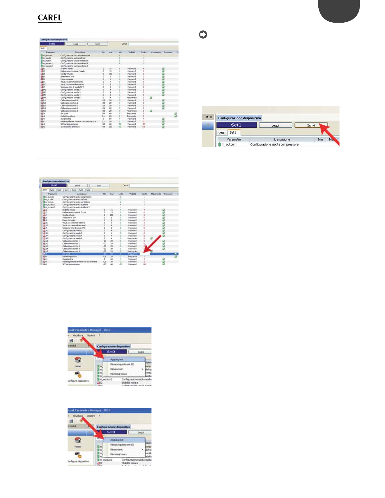
51
ENG
ir33plus +0300028EN rel. 1.1 - 05.05.2017
At the end, the list of parameters read is displayed.
Fig. 10.g
10.5 Modify a parameter
Move the cursor to the “Written” column and double click the cell: enter
the new value.
Fig. 10.h
10.6 Add a set of parameters
Up to 6 set of parameters can be added to Set0: Set0, Set1, Set2, Set3,
Set4, Set5, Set6. To do this:
• move the cursor to Set0 and click the right button; choose “Add set” for
each additional set;
Fig. 10.i
• Set1 is displayed
Fig. 10.j
Note:
• on the controller, Set0, Set1, …, Set6 are named bn0 to bn6 respectively;
• Set0 is the default set on the controller, i.e. the default con guration.
When loading a di erent set (Set1...Set6), Set0 is overwritten with the
new set and is consequently erased.
10.7 Write parameters
To write the parameters to the controller:
• Write the parameters to the key by selecting “Write”;
Fig. 10.k
• Transfer the parameters from the key to the controller using the
“Download” function, as described in the chapter on “Installation”.

52
ENG
ir33plus +0300028EN rel. 1.1 - 05.05.2017
11. APPENDIX 2: ADVANCED FUNCTIONS
11.1 Skip defrost
This algorithm is used to determine whether the shorter duration of a
defrost allows subsequent defrosts to be skipped. To enable the function,
set d12 = 2 or 3.
Par. Description Def Min Max UOM
d12 Advanced defrosts
d12 Skip defrost Automatic variation of dI
0 Disabled Disabled
1 Disabled Enabled
2 Enabled Disabled
3 Enabled Enabled
00 3 -
dn Nominal defrost duration 65 1 100 %
dH Proportional factor for variation of dI 50 0 100 dP1 Maximum defrost duration 30 1 250 min/s
dP2 Maximum aux evaporator defrost duration 30 1 250 min/s
Tab. 11.a
The nominal defrost times on evaporator 1 and evaporator 2 (auxiliary
evaporator) are determined based on parameter dn and the parameters
that set the maximum defrost duration for evaporators 1 and 2, according
to the following formulae:
dn1 =
dn
100
dP1
dn2 =
dn
100
dP2
The algorithm keeps a counter of the defrosts to be skipped:
• if the defrost ends after a time less than dn1, the counter of defrosts to
be skipped is increased by 1;
• if the defrost ends normally, the next defrost is performed;
• when the counter reaches a total of 3, 3 defrosts are skipped and then
the counter returns to 1;
• when powering on the controller, 7 defrosts are completed without
increasing the value, after which the counter is enabled (starting from
the eighth defrost).
Note: if there are two evaporators, the defrost duration used to
determine the defrosts to be skipped is the longer nominal defrost
duration.
Possible operating sequence (for example, if d12 = 2):
Start count Skip count Current count Defrost Outcome
7 0 0 Performed Not tested
6 0 0 Performed Not tested
5 0 0 Performed Not tested
4 0 0 Performed Not tested
3 0 0 Performed Not tested
2 0 0 Performed Not tested
1 0 0 Performed Not tested
0 0 0 Performed > “dn”
0 0 0 Performed > “dn”
0 0 0 Performed > “dn”
0 0 0 Performed > “dn”
0 0 0 Performed < “dn”
0 1 1 Skipped
0 1 0 Defrost > “dn”
0 0 0 Performed > “dn”
0 0 0 Performed > “dn”
0 0 0 Performed < “dn”
0 1 1 Skipped
0 1 0 Defrost < “dn”
0 2 2 Skipped
0 2 1 Skipped
0 2 0 Defrost > “dn”
0 0 0 Performed > “dn”
0 0 0 Performed > “dn”
0 0 0 Performed > “dn”
0 0 0 Performed < “dn”
0 1 1 Skipped
0 1 0 Defrost < “dn”
0 2 2 Skipped
0 2 1 Skipped
0 2 0 Defrost < “dn”
…
Tab. 11.b
11.2 Variation of the defrost interval
This algorithm is used to adjust the defrost interval based on the duration
of the previous defrost. To enable this, set d12 = 1 or 3.
The nominal defrost times on evaporator 1 and evaporator 2 are
determined based on parameter dn and the parameters that set the
maximum defrost duration for evaporators 1 and 2, according to the
following formulae:
dn1 =
dn
100
dP1
dn2 =
dn
100
dP2
With running the defrost, depending on the duration “dE”, the defrost
interval “dI” is adjusted by the value “dI”, calculated using the algorithm.
If there are two evaporators, the defrost duration considered is the longer
nominal defrost duration.
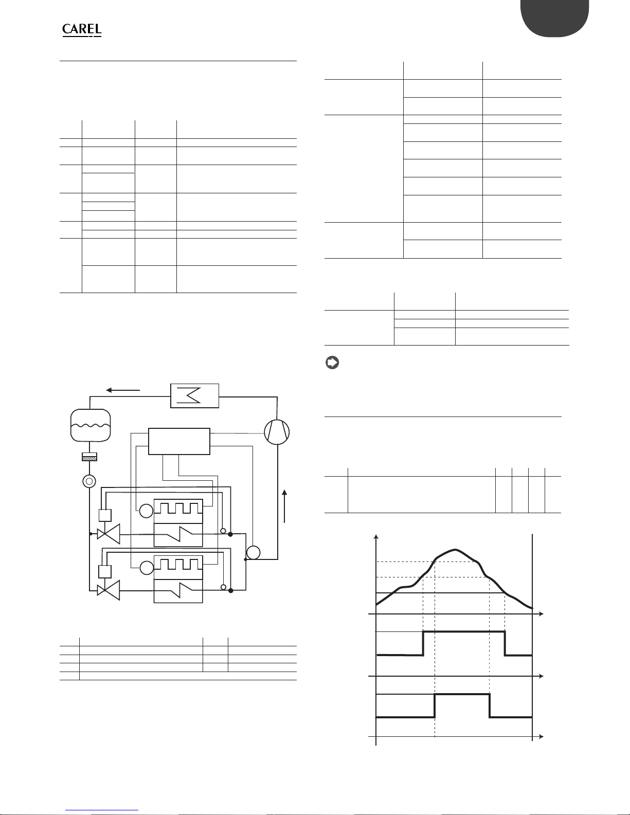
53
ENG
ir33plus +0300028EN rel. 1.1 - 05.05.2017
11.3 Defrost with 2 evaporators
Up to 3 defrost probes and up to 2 evaporator outputs can be con gured.
The controller recognises the basic con guration shown in the table
below (probe 1 is the control probe and cannot be con gured).
DEFROST PROBE AND EVAPORATOR OUTPUT CONFIGURATION
Case Defrost probes Evaporator
outputs
Notes
1 Probe 2 Evap. 1 Probe 2 acts on evap. 1
2 Probe 2 Evap. 1
and 2
Probe 2 acts on evap. 1 and 2
3 Probe 2 Evap. 1 Probes 2 and 3 act on evap. 1 (start
and end defrost refer to the probe
with the lower value)
Probe 3
4 Probe 2 Evap. 1 Probes 2, 3, 4 act on evap. 1 (start and
end defrost refer to the probe with the
lower value)
Probe 3
Probe 4
5 Probe 2 Evap. 1 Probe 1 acts on evap. 1
Probe 3 Evap. 2 Probe 2 acts on evap. 2
6 Probe 2Probe 4 Evap. 1 Probe 2 and 4 act on evap. 1 (end de-
frost if all probes > end defrost threshold.)
Probe 3Probe 4 Evap. 2 Probe 3 and 4 act on evap. 2 (end de-
frost if all probes > end defrost threshold.)
Tab. 11.c
Case 6 refers to the con guration with 1 probe on each evaporator and
1 probe in common.
CASE 6: probe 2, probe 4 on evaporator 1, probe 3, probe 4 on
evaporator 2.
C
L
CMP
T
V1
T
V2
E2
E1
S2
S3
S4
ir33+
S
F
Fig. 11.a
Key
E1/2 Evaporator 1/2 S2/3/4 Defrost probe 2, 3, 4
C Condenser CMP Compressor
V1/2 Electronic expansion valve 1/2 F Filter-drier
L Liquid receiver S Liquid gauge
V1/2 Thermostatic expansion valve 1/2
The following situations may occur if the outputs are not con gured or
there are probe alarms.
DEFROST BY TEMPERATURE
Defrost probe / evap.
output con g.
Situation E ect
Probe 2 defrost output 1 No probe Defrost ends by timeout
(dP1)
Probe available, probe
error
Defrost ends by timeout
(dP1)
Probe 3
defrost output 2
No probe
AUX1 con gured Defrost ends by timeout
(dP1)
AUX2 con gured Defrost ends by timeout
(dP2)
AUX1 and AUX2 not
con gured
Not performed
Probe available, probe
error
Defrost ends by timeout
(dP2)
Probe available and
AUX1 and AUX2 not
con gured
Defrost performed on
defrost output
Probe 4 together with
probe 2 and probe
3defrost output 1 and
defrost output 2
No probe, not managed Cases 4, 6 not reco-
gnised
Probe available, probe
error
Defrost ends by timeout
Tab. 11.d
DEFROST BY TIME
Defrost probe /
evap. output con g.
Situation E ect
Defrost output 1 AUX1 con gured Defrost ends by timeout (dP1)
AUX2 con gured Defrost ends by timeout (dP2)
AUX1 and AUX2
not con gured
Defrost not performed
Tab. 11.e
Note: AUX1 and AUX 2 con gured as evaporator outputs are not
equivalent..
11.4 Second compressor with rotation
Second compressor output with two step control and rotation. The
role of main and secondary compressor are alternated whenever the
compressor stops, so that when next called to start (or stop), the output
not involved in the previous start (stop) will be activated (deactivated).
Par. Description Def Min Max UoM
H1/H5 AUX/AUX2 output con guration
0 = normally energised alarm
…
13 = second compressor step with rotation
1/3 0 13 -
Tab. 11.f
ON
OFF
CP1
CP2
Sv
ON
OFF
St
St+rd
St+rd/2
t
t
t
Fig. 11.b
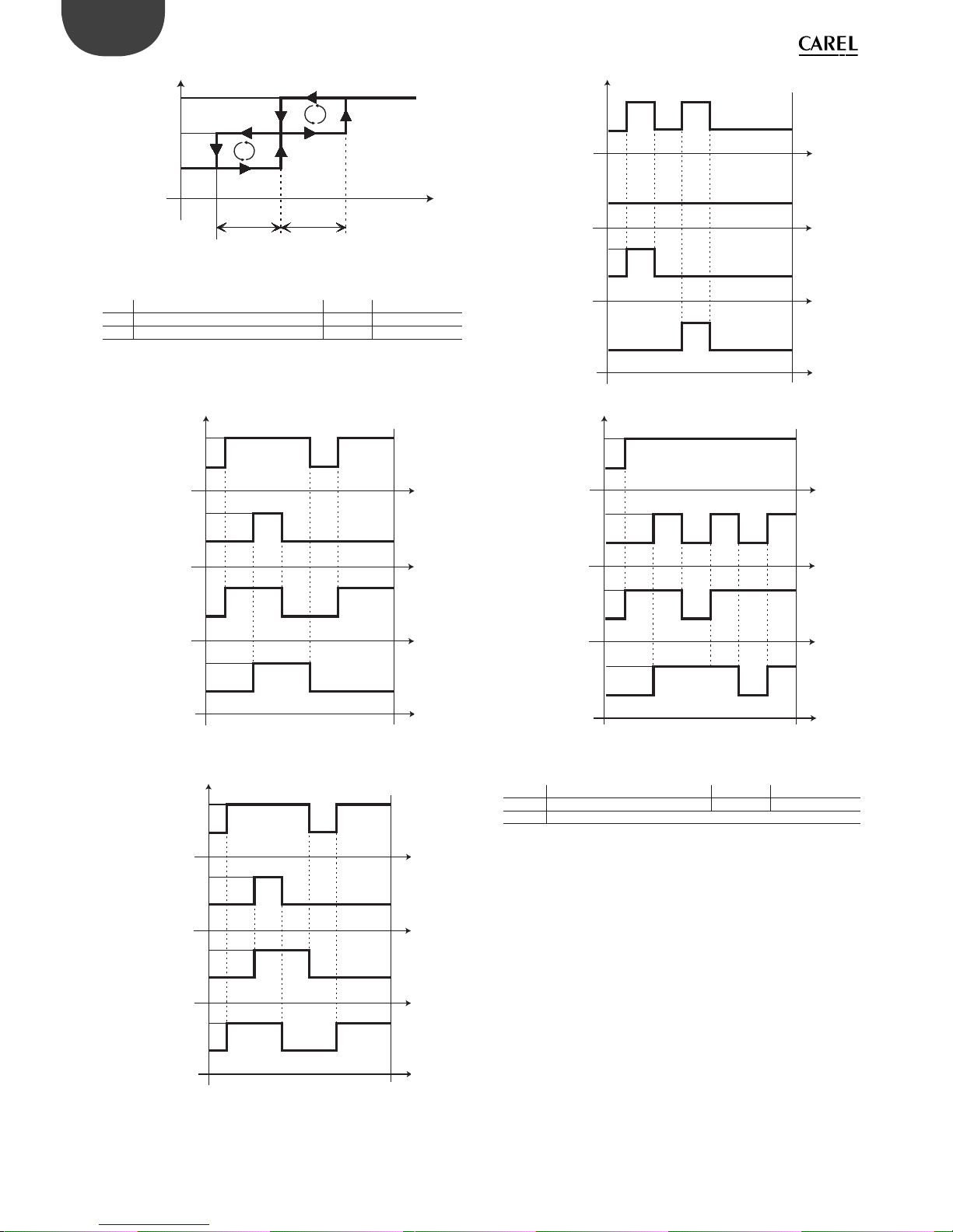
54
ENG
ir33plus +0300028EN rel. 1.1 - 05.05.2017
CP1
ON
OFF
rd/2 rd/2
CP2
ON
OFF
D
D
Sv
St
Fig. 11.c
Key
Sv Virtual probe CP2 Compressor 2
CP1 Compressor 1 rd Di erential
t time St Set point
Examples of operation:
ON
OFF
REQ2
CP1
CP2
REQ1
ON
OFF
ON
OFF
OFF
ON
EXAMPLE 1
t
t
t
t
Fig. 11.d
ON
OFF
REQ2
CP1
CP2
REQ1
ON
OFF
ON
OFF
OFF
ON
EXAMPLE 2
t
t
t
t
Fig. 11.e
ON
OFF
REQ2
CP1
CP2
REQ1
ON
OFF
ON
OFF
OFF
ON
EXAMPLE 3
t
t
t
t
Fig. 11.f
ON
OFF
REQ2
CP1
CP2
REQ1
ON
OFF
ON
OFF
OFF
ON
EXAMPLE 4
t
t
t
Fig. 11.g
Key
REQ1 compressor 1 call CP1 compressor 1
REQ2 compressor 2 call CP2 compressor 2
t time


CAREL INDUSTRIES - Headquarters
Via dell’Industria, 11 - 35020 Brugine - Padova (Italy)
Tel. (+39) 049.9716611 - Fax (+39) 049.9716600
e-mail: carel@carel.com - www.carel.com
Agenzia / Agency:
ir33plus +0300028EN rel. 1.1 - 05.05.2017
 Loading...