


High Efficiency Solutions
humiFog multizone
NO POWER
& SIGNAL
CABLES
TOGETHER
READ CAREFULLY IN THE TEXT!
pumping unit
User manual


3
ENG
“humiFog multizone - pumping unit” +0300066EN - rel. 1.2 - 10.12.2015
WARNINGS
CAREL INDUSTRIES Hq humidifiers are advanced products, whose operation is
specified in the technical documentation supplied with the product or can be
downloaded, even prior to purchase, from the website www.carel.com. Each
CAREL INDUSTRIES Hq product, in relation to its advanced level of technology,
requires setup/configuration/programming/commissioning to be able to
operate in the best possible way for the specific application. The failure to
complete such operations, which are required/indicated in the user manual,
may cause the final product to malfunction; CAREL INDUSTRIES Hq accepts
no liability in such cases.
The customer (manufacturer, developer or installer of the final equipment)
accepts all liability and risk relating to the configuration of the product in order
to reach the expected results in relation to the specific final installation and/or
equipment. CAREL INDUSTRIES Hq may, based on specific agreements, act as
a consultant for the installation/commissioning/use of the unit, however in no
case does it accept liability for the correct operation of the humidifier and the
final installation if the warnings or suggestions provided in this manual or in
other product technical documents are not heeded. In addition to observing
the above warnings and suggestions, the following warnings must be heeded
for the correct use of the product:
• DANGER OF ELECTRIC SHOCK
• The humidifier contains live electrical components. Disconnect the mains
power supply before accessing inside parts or during maintenance and
installation;
• DANGER OF WATER LEAKS
• The humidifier automatically and constantly fills/drains certain quantities of
water. Malfunctions in the connections or in the humidifier may cause leaks;
• For isothermal humidiers: DANGER OF BURNS
• The humidifier contains high temperature components (100°C/212°F);
• For gas-red isothermal humidiers: DANGER OF GAS LEAKS
• The humidifier is connected to the gas mains. Malfunctions in the
connections or inside the humidifier may cause gas leaks.
• The installation of the product must include an earth connection, using the
special yellow-green terminal available in the humidifier.
• The environmental and power supply conditions must conform to the
values specified on the product rating labels.
• The product is designed exclusively to humidify rooms either directly or
through distribution systems (ducts). In addition, for adiabatic-water spraypressure humidifiers, humidification also occurs through the atomisation
rack.
• Only qualified personnel who are aware of the necessary precautions and
able to perform the required operations correctly may install, operate or
carry out technical service on the product.
• Only water with the characteristics indicated in this manual must be used
for steam or water vapour production.
• Warning, demineralised drinking water must be used for adiabatic-water
spray-pressure humidifiers (as specified in the manual). In addition, the
particles of water not absorbed by the air must be removed into the
droplet collection tank (in the humidification section) and by the droplet
separator (at the end of the humidification section).
• All operations on the product must be carried out according to the
instructions provided in this manual and on the labels applied to the
product. Any uses or modifications that are not authorised by the
manufacturer are considered improper. CAREL INDUSTRIES Hq declines all
liability for any such unauthorised use.
• Do not attempt to open the humidifier in ways other than those specified
in the manual.
• Observe the standards in force in the place where the humidifier is installed.
• Keep the humidifier out of the reach of children and animals.
• Do not install and use the product near objects that may be damaged when in
contact with water (or condensate). CAREL INDUSTRIES Hq declines all liability
for direct or indirect damage following water leaks from the humidifier.
• Do not use corrosive chemicals, solvents or aggressive detergents to clean
the inside and outside parts of the humidifier, unless specifically indicated
in the user manual.
• Do not drop, hit or shake the humidifier, as the inside parts and the linings
may be irreparably damaged.
• For adiabatic-water spray-pressure humidifiers: the atomised water must
be distributed using a special atomising ‘rack’ or through distribution
systems specified by CAREL INDUSTRIES Hq
• For isothermal appliances: these are designed to produce steam at
atmospheric pressure, and not pressurised steam. CAREL INDUSTRIES Hq
does not recommend and waives all liability for the use of distribution
devices other than those specified.
CAREL INDUSTRIES Hq adopts a policy of continual development.
Consequently, CAREL reserves the right to make changes and improvements
to any product described in this document without prior warning. The
technical specifications shown in the manual may be changed without prior
warning.
The liability of CAREL INDUSTRIES Hq in relation to its products is specified
in the CAREL INDUSTRIES Hq general contract conditions, available on the
website www.carel.com and/or by specific agreements with customers;
specifically, to the extent where allowed by applicable legislation, in no case
will CAREL INDUSTRIES Hq, its employees or subsidiaries be liable for any lost
earnings or sales, losses of data and information, costs of replacement goods
or services, damage to things or people, downtime or any direct, indirect,
incidental, actual, punitive, exemplary, special or consequential damage of any
kind whatsoever, whether contractual, extra-contractual or due to negligence,
or any other liabilities deriving from the installation, use or impossibility to use
the product, even if CAREL INDUSTRIES Hq or its subsidiaries are warned of the
possibility of such damage.
DISPOSAL
The humidifier is made up of metal parts and plastic parts. In reference to
European Union directive 2002/96/EC issued on 27 January 2003 and the
related national legislation, please note that:
1. WEEE cannot be disposed of as municipal waste and such waste must be
collected and disposed of separately;
2. the public or private waste collection systems defined by local legislation must
be used. In addition, the equipment can be returned to the distributor at
the end of its working life when buying new equipment;
3. the equipment may contain hazardous substances: the improper use or
incorrect disposal of such may have negative effects on human health
and on the environment;
4. the symbol (crossed-out wheeled bin) shown on the product or on the
packaging and on the instruction sheet indicates that the equipment has
been introduced onto the market after 13 August 2005 and that it must
be disposed of separately;
5. in the event of illegal disposal of electrical and electronic waste, the penalties
are specified by local waste disposal legislation.
Warranty on the materials: 2 years (from the date of production, excluding
consumables).
Approval: the quality and safety of CAREL INDUSTRIES Hq products are
guaranteed by the ISO 9001 certified design and production system, as well
as by the following marks.
WARNING: separate as much as possible the probe and digital input signal
cables from the cables carrying inductive loads and power cables to avoid
possible electromagnetic disturbance.
Never run power cables (including the electrical panel wiring) and signal
cables in the same conduits.
NO POWER
& SIGNAL
CABLES
TOGETHER
READ CAREFULLY IN THE TEXT!


5
ENG
“humiFog multizone - pumping unit” +0300066EN - rel. 1.2 - 10.12.2015
Content
1. INTRODUCTION AND ASSEMBLY 7
1.1 Description of humiFog ..........................................................................................7
1.2 Components in the system ..................................................................................7
1.3 humiFog system configurations ........................................................................7
1.4 Supply water characteristics.................................................................................7
1.5 Periodic checks for consumables ......................................................................8
1.6 Dimensions and weights ........................................................................................8
1.7 Components (master/slave) .................................................................................9
1.8 Electrical specifications.........................................................................................10
1.9 Opening the packaging .......................................................................................10
1.10 Positioning the cabinet ......................................................................................11
1.11 Opening the cabinet door ................................................................................12
1.12 Components and accessories .........................................................................12
2. WATER CIRCUIT CONNECTIONS 13
2.1 Water circuit installation: instructions .........................................................13
2.2 Water circuit installation: checklist ................................................................13
3. ELEC TRICAL CONNECTIONS 14
3.1 Power supply .............................................................................................................15
3.2 Remote ON/OFF .......................................................................................................15
3.3 Control signals from external voltage-free contact (humidistat) .....15
3.4 Modulating control signal (J2) .........................................................................16
3.5 Heat recovery signal ...............................................................................................17
3.6 Solenoid valve connection for distribution system ............................17
3.7 Water treatment unit contact ...........................................................................18
3.8 Cumulative alarm relay (J15) .............................................................................18
3.9 Pump state contact ...............................................................................................18
3.10 Pump life signal .........................................................................................................18
3.11 Alarm inputs from external devices ...........................................................19
3.12 Backup/rotation (redundancy) ........................................................................19
3.13 Expansion mode/remote actuator ................................................................19
3.14 Master-slave connection .....................................................................................20
3.15 Supervisor network .................................................................................................20
4. PUMPING UNITS 21
4.1 Pumping unit with flow control configuration .....................................21
4.2 Pumping unit with constant pressure control .......................................21
5. DISTRIBUTION SYSTEM 22
5.1 Air handling unit: distribution, atomisation system and
droplet separator ......................................................................................................22
5.2 Direct humidification into the room: distribution and
atomisation system .................................................................................................22
6. APPLICATIONS 23
6.1 Main advantages of humiFog multizone ..................................................23
7. CONTROL 24
7.2 Evaporative Cooling ...............................................................................................25
8. SINGLE ZONE AND MULTIZONE CONFIGURATION 27
8.1 Single zone ...................................................................................................................27
8.2 Multizone application in AHU or room ......................................................28
8.3 Indirect adiabatic cooling applications ......................................................30
8.4 System operation .....................................................................................................30
8.5 Constant pressure systems: notes on capacity control ....................31
9. START UP 32
9.1 Starting ...........................................................................................................................32
9.2 Stopping ........................................................................................................................32
9.3 First start-up .................................................................................................................32
10. USER INTERFACE 33
11. TABLE OF ALARMS 49
12. WIRING DIAGR AMS 52
12.1 Wiring diagram humiFog multizone - Master - CE -
MONOFASE ...................................................................................................................52
12.2 Wiring diagram humiFog multizone - Master - CE -
TRIFASE
(solo per UA10K***) .......................................54
12.3 Wiring diagram humiFog multizone - Master - UL -
MONOFASE ...................................................................................................................56
12.4 Wiring diagram humiFog multizone - Master - UL - TRIFASE .......58
12.5 Wiring diagram humiFog multizone - Slave - CE ................................60
12.6 Wiring diagram humiFog multizone - Slave - UL ................................62


7
ENG
“humiFog multizone - pumping unit” +0300066EN - rel. 1.2 - 10.12.2015
installeruserservice
1. INTRODUCTION AND ASSEMBLY
1.1 Description of humiFog
humiFog is a humidifier and adiabatic cooler that atomises demineralised
water into very fine droplets that evaporate spontaneously in the air,
which is humidified and cooled.
humiFog uses a volumetric pump to pressurise the water, which is
atomised by special stainless steel nozzles.
The sophisticated control system combines the action of an inverter,
which controls the speed and consequently the flow-rate of the pump,
with a series of solenoid valves that activate only the nozzles that are
necessary, allowing the system to always operate at the ideal pressure
to atomise the water, across a wide range of flow-rates (a 5-100 % flow
range working with a constant pressure of 14-100% for operating while
controlling the flow).
The effect of cooling the air is due to the spontaneous evaporation of
the droplets of water: the change in state from liquid to steam occurs by
subtracting energy from the air that, as a consequence, is cooled. Each
kilogram of water evaporated absorbs 0.69 kWh of heat from the air.
humiFog is a complete humidification and/or adiabatic cooling system
that can be used both in AHUs (air handling units) and to humidify or cool
industrial environments by spraying water directly into the environments.
The term zone refers to both AHUs and industrial environments.
1.2 Components in the system
humiFog is made up of:
• a pumping unit that delivers the water at high pressure (25-70 bars).
It also contains the electronic controller that completely manages the
pumping unit, controlling the temperature/humidity in a zone (either
AHU or environment) and managing any other zones connected to
the pumping unit;
• The pumping unit can be set to operate:
- with flow control (maximum precision, minimum energy and water
consumption, only single zone applications);
- at constant pressure (suitable for multizone applications where one
pumping unit supplies the humidification and/or cooling system in
different zones);
• distribution and atomisation system: system of pipes carrying the
pressurised water that house the atomisation nozzles and, in general,
the capacity-control solenoid valves and drain solenoid valves;
• droplet separator (only when installed in an AHU);
• temperature and/or humidity probes (if necessary);
• water treatment system: typically this is a reverse osmosis demineraliser
that supplies water with a low mineral salt content to the humiFog.
1.3 humiFog system configurations
The humiFog system can be used in the following configurations:
• single zone: for humidification and/or cooling applications in a AHU or
an industrial environment;
• multizone: for applications where one pumping unit (master) is
used to supply multiple zones with pressurised water. The master
will control one zone, in the sense that in relation to the zone probe
readings or the external controller, it will activate and control the
distribution and atomisation system so as to maintain the humidity or
temperature level. All other zones will have a controller (slave electrical
panel) that communicates with the master, and in relation to the zone
probe readings or the external controller will activate and control the
distribution atomisation system so as to maintain the humidity or
temperature level.
One important configuration is for indirect adiabatic cooling applications:
a pumping unit can be used to humidify the air in winter and to cool
the discharged air in summer before it enters a heat recovery unit. This
configuration is explained in detail in the chapters below.
humiFog humidifiers are available for:
• maximum flow-rates respectively of 100 l/h,(UA100..) 200 l/h (UA200..),
320 l/h (UA320..), 460 l/h (UA460..), 600 l/h (UA600..);
• type of cabinet: H=single zone master; Z=multizone master; S=slave
cabinet;
• power supply voltage: D= 230 V 50 Hz; U= 208 V 60 Hz;
• shows the version of the launched product (1 - 4)
• damper: 0=without damper; 1=with damper (only versions with 100
and 200 l/h flow-rate)
• features of the pump and circuits: 0= brass; 1=stainless steel; 2=
stainless steel, silicon free
1.4 Supply water characteristics
Why does humiFog require demineralised water?
Humifog only works with demineralised water, to ensure:
• minimum maintenance;
• no blockage of the nozzles;
• no dust (the droplets that evaporate do not leave mineral salts in the
AHU/environment);
• more hygiene.
The use of demineralised water is also required by standards such as
UNI8883 , VDI6022, VDI3803
humiFog must only be supplied with treated water, based on the limit
values listed below. In normal circumstances, this means that the water
must be treated using a reverse osmosis system.
recommended supply water characteristics unit of
measure
limits
min. max.
bH (**)(pH)
6,5 8,5
Specific conductivity at 20°C (**) (σR, 20°C) for steel
pump
µS/cm 0 30
Specific conductivity at 20°C (**) (σR, 20°C) for brass
pump
µS/cm 30 50
Total hardness (**) (TH) mg/l CaCO3 0 25
Temporary hardness mg/l CaCO3 0 15
Total quantity of dissolved solids (cR) mg/l
(*) (*)
Dry residue at 180° (R180°C) mg/l
(*) (*)
Iron + Manganese mg/l Fe+Mn 0 0
Chlorides ppm Cl 0 10
Silicon dioxide mg/l SiO2 0 1
Chlorine ions mg/l Cl- 0 0
Calcium sulphate mg/l CaSO4 0 5
Tab. 1.a
(*) values depend on the specific conductivity; in general:
CR 0,65 * σ
R, 20 °C
; R
180
0,93 * σ
R, 20 °C
(**) main values to keep in consideration for every type installation.
Important: If the specific conductivity is less than 30 µS/cm, the
stainless steel pump should be used.
Important:
(**)
for conductivity values around “0”, contact CAREL
INDUSTRIES for operating suggestions.
Caution: for conductivity higher than 1000 S/cm, it is required to
pre-treat the water before subjecting it to reverse osmosis.
Caution: the pump is able to operate at a maximum temperature of
40°C.

8
ENG
“humiFog multizone - pumping unit” +0300066EN - rel. 1.2 - 10.12.2015
installeruserservice
1.5 Periodic checks for consumables
Summary table of checks and maintenance:
Pump
Check/Replace monthly every 1000 h
Water filters X
Oil level X
Replace oil X
Check/replacement gasket and valves X
Attention: after the first 50 h of exercise you need to replace the oil
pump.
Attention: if the “1000h” check does not identify any leaks or
malfunctions, then the possibility to postpone the replacement
shall be assessed. Typically, in optimum operating conditions, this process
is necessary around 3000 h of operation.
Rack/distribution system
visually check every 1000 h
obstructed nozzles X
solenoid valves X
accessories X
drain and water X
droplet separator X
Tab. 1.b
Installations in AHUs or ducts must also comply with national maintenance
standards (ASHRAE 12-2000, VDI 6022, UNI 8884, VDI 3803, etc.)
Please note that:
• maintenance personnel must reset the hour counter after having
performed the preventive maintenance operations listed in the
columns “after 50 hours” and “every 1000 hours”. If the hour counter
is not reset, the maintenance warnings will no longer be signalled
(to reset the hour counter, see the information under Section 9.8
Maintenance menu/submenu f/screen 02);
• maintenance personnel are responsible for any malfunctions due to a
lack of preventive maintenance. The controller will display maintenance
warning code “C5” after the first 50 hours and, subsequently, routine
maintenance warning code “CL” every 2000 hours, as a reminder for
the operations listed;
• failure to change the oil after the first 50 hours of operation may cause
oil leaks and serious damage to the pumps, reducing operating life;
• maintenance signals do not stop the operation of humiFog.
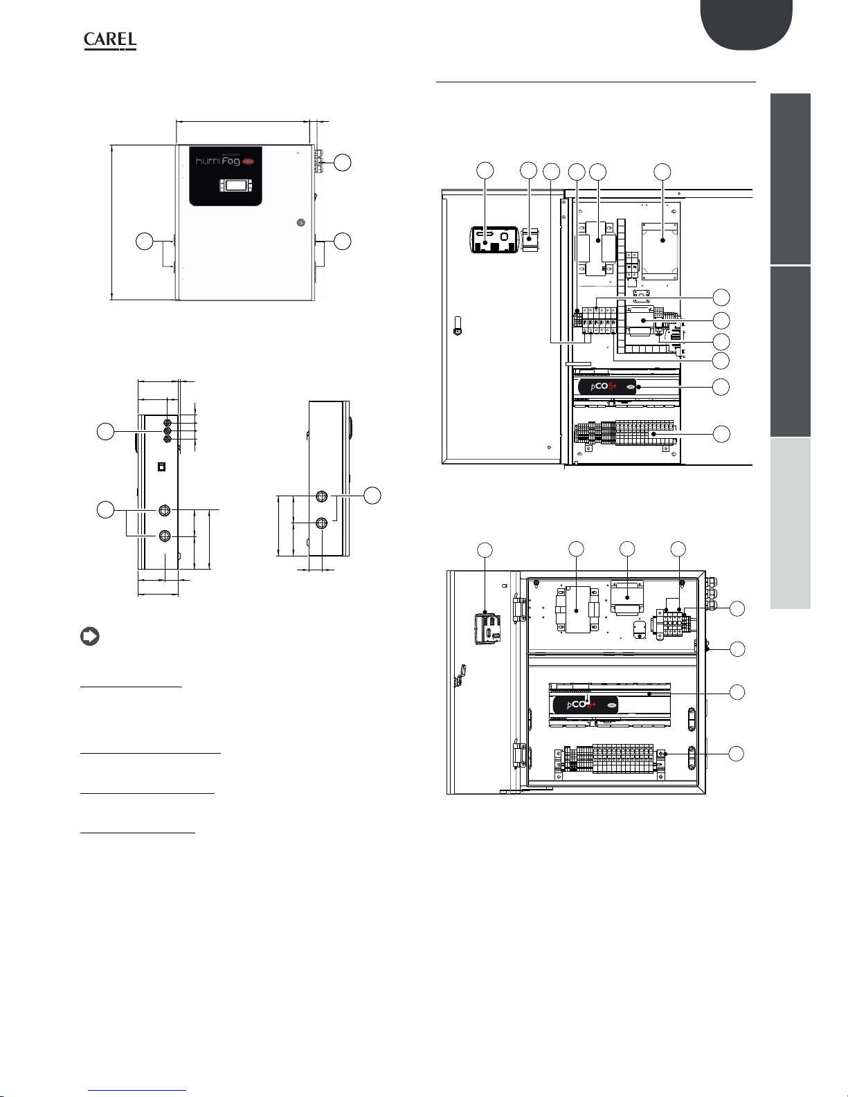
1.6 Dimensions and weights
Humifog master
front view
1030
20
135
550
70
360
860
1
2
3
4
5
6
Fig. 1.a
detail of cabinet, water inlet/outlet
side view
electrical connection side view
90
554
135
2055
105
2558
3
4
5
6
70
360
430
75
75
4040 40 4040
2
1
Fig. 1.b
Key:
1. power supply inlet;
2. terminal block inlet;
3. water inlet;
4. water outlet;
5. drain
6. drain bypass..
N.B.: inlets for electrical connections ready to be cut out, opening
and cable gland installation to be performed by the installer
Packaging dimensions:
• height (H): 1020 mm (40.16 inch);
• width (W) 1100 mm (43.30 inch);
• depth (D) 455 mm (17.50 inch).
Weight of packaged humidifier:
• UA(100,200)(H,Z)4** models: 100 kg (220 lb);
• UA(320,460)(H,Z)4** models: 110 kg (240 lb);
• UA600(H,Z)4** models: 120 kg (265 lb);
• UA1K0(H,Z)4** models: 125 kg (276 lb);
Weight of installed humidifier:
• UA(100,200)(H,Z)4** models: 85 kg (190 lb);
• UA(320,460)(H,Z)4** models: 95 kg (210 lb);
• UA600(H,Z)4** models: 100 kg (220 lb);
• UA1K0(H,Z)4** models: 105 kg (230 lb);
Mechanical specifications:
• Installation: floor standing;
• IP20; (enclosure type 1).
• cabinet operating conditions: 1 to 40 °C (34 to 104 °F) <80 % RH non-
condensing;
• storage conditions: 1 to 50 °C (34 to 122 °F) <80 % RH non-condensing
9
ENG
“humiFog multizone - pumping unit” +0300066EN - rel. 1.2 - 10.12.2015
installeruserservice
Humifog slave
front view
500 28
580
1
22
Fig. 1.c
detail of cabinet, air & water inlet side
view
detail of cabinet, outlet side view (to
nozzles)
150 8
303030
40110
101
50100
150
123
224
1
2
123 101
50
224
2
Fig. 1.d
N.B.: inlets for electrical connections ready to be cut out, opening
and cable gland installation to be performed by the installer
Packaging dimensions:
• height (H): 770 mm (30.14 inch);
• width (W) 605 mm (23.82 inch);
• depth (D) 255 mm (10.00 inch).
Weight of packaged humidifier:
• UA000S(D,U)400 models: 21 kg (46.3 lb);
Weight of installed humidifier:
• UA000S(D,U)400 models: 19.5 kg (43 lb);
Mechanical specifications:
• Installation: wall mounted;
• IP20; (enclosure type 1)
• cabinet operating conditions: 1 to 40 °C (34 to 104 °F) <80 % RH non-
condensing;
• storage conditions: 1 to 50 °C (34 to 122 °F) <80 % RH non-condensing
1.7 Components (master/slave)
Electrical components
Master cabinet
F1 F2 F6
F8
F7
F9
1
3
6
4
2
5
9
7
10
8
11
12
Fig. 1.e
Slave cabinet
1
2
8
6
4
3
11
12
Fig. 1.f
Key:
1. terminal rear view.
2. transformer B.
3. main switch G.
4. power supply terminal block.
5. VFD inverter.
6. transformer primary fuse carrier (TRA: F1,F2; TRB:F3,F4).
7. inverter fuse carrier (F6, F7).
8. transformer B secondary fuse carrier (F8).
9. transformer A.
10. start relay K.
11. electronic controller;
12. control terminal block plus fuses

10
ENG
“humiFog multizone - pumping unit” +0300066EN - rel. 1.2 - 10.12.2015
installeruserservice
Water circuit components
12
7
5
6
8
9
11
10
13
23 4
1
Fig. 1.g
16
15
14
17
Fig. 1.h
Key:
1. inlet water pressure reducer with filter;
2. 1st pressure gauge, inlet;
3. water filter;
4. minimum pressure switch (1 bar);
5. 2nd pressure gauge, downstream of the water filter;
6. conductivity sensor;
7. water supply solenoid valve;
8. motor;
9. pulsation damper;
10. outlet pressure gauge, high pressure side;
11. piston pump;
12. maximum pressure switch (95 bars);
13. high pressure control valve;
14. thermostat (70 °);
15. bypass solenoid valve;
16. temperature probe;
17. pressure transducer
18. drain bypass.
1.8 Electrical specifications
MASTER 50 HZ
model UA100*D4** UA200*D4** UA320*D4** UA460*D4** UA600*D4** UA1K0*HL4*
VAC 230 V 230 V 230 V 230 V 230 V 400 V
phases 1 1 1 1 1 3
Hz 50 -60 Hz 50 -60 Hz 50 -60 Hz 50 -60 Hz 50 -60 Hz 50-60 Hz
power 0,955 kW 0,955 kW 1,150 kW 1,150 kW 1,95 kW 4 kW
current 7,0 A 7,0 A 9,2 A 9,2 A 12,0 A 4,6 A
Product in compliance with EN55014, EN61000, EN60204.
Insulation grade III
MASTER 60 HZ
model UA100*U4** UA200*U4** UA320*U4** UA460*U4** UA600*U4** UA1K0*HM4*
VAC 230 V 230 V 230 V 230 V 230 V 460 V
phases 1 1 1 1 1 3
Hz 60 Hz 60 Hz 60 Hz 60 Hz 60 Hz 60 Hz
power 0,955 kW 0,955 kW 1,150 kW 1,150 kW 1,95 kW 2.75 kW
current 8,00 A 8,00 A 10,20 A 10,20 A 13 A 4.8 A
FLA 1HP/8 A 1HP/8 A 2HP/12 A 2HP/12 A 3HP/17 A 3HP/6.1 A
SCCR 5KA 5KA 5K A 5K A 5KA 5K A
Product in compliance with UL998
SLAVE
model UA000SD400 UA000SU400
VAC 230 V 208 V
phases 1 1
Hz 50 Hz 60 Hz
power 0,280 kW 0,280 kW
current 2,20 A 2,50 A
FLA - 3/4HP
SCCR - 5KA
Product in compliance with UL998
Tab. 1.c
1.9 Opening the packaging
make sure the humidifier is intact upon delivery and immediately
notify the transporter, in writing, of any damage that may be due to
careless or improper transport;
move the humidifier to the site of installation before removing from
the packaging, grasping the neck from underneath;
for the master cabinet:
position the cabinet near the site of installation (still packaged on the
pallet);
remove the packaging;
unscrew the bolts and remove the pallet (the cabinet is secured to the
bottom of the pallet using 4 bolts);
for the slave cabinet:
open the cardboard box, remove the protective material and remove
the humidifier, keeping it vertical at all times.
Keep the packaging in a cool and dry environment (cardboard box, pallet,
4 bolts used to secure the cabinet to the pallet) for reuse.

11
ENG
“humiFog multizone - pumping unit” +0300066EN - rel. 1.2 - 10.12.2015
installeruserservice
1.10 Positioning the cabinet
Both cabinets: master and slave, should be positioned so as to guarantee
the following:
• read the values on the display;
• access the keypad on the display;
• open the front panels;
• access to the inside parts for checks and maintenance;
• connection of the water supply lines;
• connection to the water distribution lines;
• power and control connections;
• prepare a base of at least 200 mm.
in particular, for the Master cabinet:
It can be positioned wherever the following conditions are ensured:
• clearance for routine maintenance as described in Fig. 1.f
• humidity 20-80% rH non-condensing
• temperature 1-40 °C;
• cabinet compliant with seismic testing standards IEC 60068-2-6, IEC
60068-2-57, IEC 60068-2-64, ISO2041. To ensure compliance with the
above-mentioned standards, the cabinet must be anchored to the
floor using the threaded holes provided (M6 female thread), as shown
in Fig. 1.i.
65
900
65
20 20
310
INSERTI FILETTATI M6
FEMMINA
65
900
65
M6 F
20
310
20
M6 F
Fig. 1.i
Important: the maximum distance between the cabinet and rack/
distribution system is 50 metres, for higher distances contact CAREL
INDUSTRIES.
Positioning procedure:
• after opening the packaging:
• position the cabinet in the final position;
• level the cabinet horizontally.
TV
3751000
100
1075
55
45
100 100
P
Fig. 1.j
Slave cabinet
Fasten it to a solid support surface using the screws and bracket supplied.
Make sure there is enough space for the electrical power supply and
control connections.
rear of the cabinet
390
200
440
drilling template
440
200
390
= =
= =
Fig. 1.k

12
ENG
“humiFog multizone - pumping unit” +0300066EN - rel. 1.2 - 10.12.2015
installeruserservice
1.11 Opening the cabinet door
Master cabinet
Opening Fig. 1.h:
1. Release the water circuit panel:
use a flat-head screwdriver (max. 8 mm);
turn anticlockwise until releasing the panel.
2. Remove the panel:
tilt the panel and lift it.
Closing Fig. 1.h:
3. Reposition the water circuit panel:
Important: insert the bottom pins of the panel in the corresponding
holes (F).
4. Lock the panel:
use a flat-head screwdriver (max. 8 mm);
turn clockwise until the panel is secured
Fig. 1.l
Slave cabinet
1. press and turn anticlockwise with a flat-head screwdriver (max 8 mm)
until releasing the panel;
2. open the cabinet door by turning it to the left.
1
2
Fig. 1.m
1.12 Components and accessories
Once having opened the packaging and removed the front cover of the
humidifier, make sure the following are included:
for master units:
• tool for opening the water inlet filter casing;
• PG13 and PG21 cable glands for the electrical connections (CE versions
only).
• yellow/black pump motor oil cap, to replace the red cap on the pump.
for slave units
• kit of screws with plugs for wall-mounting;
• PG13 and PG21 cable glands for the electrical connections (CE versions
only).

13
ENG
“humiFog multizone - pumping unit” +0300066EN - rel. 1.2 - 10.12.2015
installeruserservice
2. WATER CIRCUIT CONNECTIONS
2.1 Water circuit installation: instructions
The water connections are
•
water inlet;
• high pressure water outlet to the rack (see ”connecting the cabinet to
the rack” in the distribution manual);
• water drain.
Water circuit installation: instructions
To simplify installation and maintenance, install a manual valve
immediately before connecting the water inlet to the cabinet (this valve
is not supplied by CAREL).
humiFog only operates on demineralised water, preferably from a
reverse osmosis system. The specifications and the limits of the water are
described in detail in chap. 1.4 “supply water characteristics”.
1. open the water circuit (vedi par. 1.10 “Opening the cabinet door”):
2. connect the water supply hose:
• the supply hose connection fitting is G1/2”F (NPT1/2”F - UL 60 Hz
version).
• the inside diameter of the supply hose must not be less than
13 mm.
• run the water supply hose through hole “3” Fig. 1.a.
Water drain connection
1. connect the drain “5” Fig. 1.a to the drain system:
• use a hose with inside diameter 10 mm, resistant to demineralised
water.
• connect the hose to the drain connection underneath the cabinet
using a hose clamp.
N.B.: the hose and the clamp are not supplied by CAREL, to
tighten clamp, lift the cabinet.
2. connect the drain bypass “6” Fig. 1.a to the drain system.
Replacing the top oil cap on the pump
1. replace the top oil cap on the pump:
• replace the TOP oil cap ( (Fig. 2.a, A), used for transport only, with
the CAP WITH THE VENT HOLE (Fig. 2.a, B) used in normal operation;
• keep closed cap for future transport.
2. reposition the front panel on the water circuit and close it.
Fig. 2.a
CE versions
model UA100*D4** UA200*D4** UA320*D4** UA460*D4** UA600*D4** UA1K0*HL4*
max flow
rate (l/h;
lb/h;Gd)
100 200 320 460 600 950
220 441 705 1014 1323 2095
634 1268 2028 2916 3805 6023
inlet
pressure
(Mpa,Bar,
PSI)
0,3…0,8 Mpa
3…8 Bar
40…100 PSI
temperat. 1T40 ºC / 34T104 ºF
input G1/2”F G1/2”F
adapter
outlet
(pump)
M16,5m DIN 2353 (G3/8”F) M22,5m
DIN 2353
(G1/2”F)
main
drain
G1/2”F
drain
tray
External stainless steal pipe φ 10 mm/ 0.4 inch
Tab. 2.a
UL versions
model UD100*U4** UD200*U4** UD320*U4** UD460*U4** UD600*U4** UA1K0*HM4*
max flow
rate (l/h;
lb/h;Gd)
100 200 320 460 600 950
220 441 705 1014 1323 2095
634 1268 2028 2916 3805 6023
inlet
pressure
(Mpa,Bar,
PSI)
0,3…0,8 Mpa
3…8 Bar
40…100 PSI
temperat. 1T40 ºC / 34T104 ºF
input NPT 1/2”F (with adapter G1/2” M - NPT 1/2” F)
adapter
outlet
(pump)
NPT3/8F NPT1/2F
main
drain
NPT 1/2”F (with adapter G1/2” M - NPT 1/2” F)
drain
tray
External stainless steal pipe φ 10 mm/ 0.4 inch
Tab. 2.b
2.2 Water circuit installation: checklist
humiFog system name: _____________________________________
Description / notes
Cabinet level
Distance between cabinet-rack/water distribution system: ≤50 m.
Water supply connection
Water inlet pressure ≥3 bars (0.3 MPa, 40 PSI)
Filters filled with water
Drain connected to the water drain system
drain bypass: TFN8x10 NYLON WHITE hose connected to the water
drain
Pump: oil cap replaced with the cap featuring the vent
Supply water within the limit values See the section on “Supply water
characteristics””
Date: _______________
Signature: _______________________________________

14
ENG
“humiFog multizone - pumping unit” +0300066EN - rel. 1.2 - 10.12.2015
installeruserservice
3. ELECTRICAL CONNECTIONS
Master version
F1 F2 F6
F8
F7
F9
1
J15
4
5
J20
J19
J6
J2
3
2
J3
Fig. 3.a
Slave version
J15
4
1
5
J6
3
2
J3
J2
Fig. 3.b
Legenda:
1 L/N/GR Power supply
Important
• make sure that the cable glands
are fitted
• do not run the control and signal
cables through this cable gland.
J2 U1 Main humidity/temperature probe
U2 Limit humidity/temperature probe
U3 AUX probe (temperature display
only)
J3 U5 Segnale recuperatore di calore per
EC, uscita configurabile sia analogi-
ca che digitale
J6 U8 rack temperature probe
J15 NO8 Cumulative alarm relay
J19 NO24 Pumping unit signal
J20 NO27 Pumping unit enable signal
2 PEN/G0A Pumping unit remote enabling
signal
ROAL/G0A Water treatment system control
BKUP/G0A Back up cabinet signal
ROEN/COM comand for water treatment system
ON-OFF/G0A Control signals from external con-
tact type humidistat ON/OFF
RKEN/G0A RACK production enable
FLUX/G0A Air flow
3 NC1÷NC6/GOB Slicing solenoid valves step
NO1÷NO6/GOB Drain solenoid valve step
NOL Drain solenoid valve line
NOV Fan solenoid valve (rack)
4 Field card Field card input for Master Slave
connection
5 Serial Card Serial card input for BMS (Building
Management Systems)
N.B.: feature adequate protection on all activation
outputs to external devices.

15
ENG
“humiFog multizone - pumping unit” +0300066EN - rel. 1.2 - 10.12.2015
installeruserservice
3.1 Power supply
Depending on the model:
• UA****D4** voltage 230 V 1~ 50Hz
• UA****U4** voltage 230 V 1~ 60Hz
• UA1k0*HL4* voltage 400 V 3~ 50Hz
• UA1k0*HM4* voltage 460 V 3~ 60Hz
Important: The cables must conform to local standards.
Install a power switch outside the humidifier to completely isolate
the mains power supply, with earth fault protection (30 mA).
GR
L
N/W
GR
N/W
L
L
N/W
GR
L
N/W
GR
MASTER
SLAVE
GR
L2
L1
GR
L1
L2L3L3
400V Trifase
230V Monofase
Fig. 3.c
CONNECTIONS
Cabinet master - slave 230V Monophase Powersupply cable
L L/F (fase) AWG13 (2,5 mm)
N N/W (neutro) AWG13 (2,5 mm)
GR GR/PE (terra) AWG13 (2,5 mm)
Cabinet master 400/460V Threephase Powersupply cable
L1 L1 (fase 1) AWG13 (2,5 mm)
L2 L2 (fase 2) AWG13 (2,5 mm)
L3 L3 (fase 3) AWG13 (2,5 mm)
GR GR/PE (terra) AWG13 (2,5 mm)
3.2 Remote ON/OFF
Cables • up to 30 m: two-wire cable AWG20/22
electrical specifications of the
contact:
voltage-free contact
GR
PEN
GR
PEN
ROAL
ROAL
BKUP
BKUP
ROEN
ROEN
COM
COM
ONOF
ONOF
RKEN
RKEN
FLUX
FLUX
G0B
G0B
G0A
G0A
G0A
G0A
G0A
G0A
G0B G0B G0B G0B G0B
G0B G0B G0B G0B G0B
21
Fig. 3.d
Key:
1. Pump remote ON/OFF
2. Zone remote ON/OFF
CONNECTIONS
humiFog Master cabinet Remote ON/OFF
PEN (enable pump) NC/NO
RKEN (enable master rack) NC/NO
G0A COM
humiFog Slave cabinet Remote ON/OFF
RKEN (enable slave rack) NC/NO
G0A COM
N.B.: the Master unit is supplied with contacts PEN-G0A and RKENG0A jumpered, the Slave unit is supplied with contact RKEN-G0A
jumpered
3.3 Control signals from external voltagefree contact (humidistat)
a) ON/OFF (C control)
Cables • up to 30 m: two-wire cables cross-section 0.5 mm2
(AWG20)
• greater than 30 m: shielded cables cross-section 1.5
mm
2
(AWG15)
electrical specifications of
the contact
voltage-free contact
GR
PEN
GR
PEN
ROAL
ROAL
BKUP
BKUP
ROEN
ROEN
COM
COM
ONOF
ONOF
RKEN
RKEN
FLUX
FLUX
G0B
G0B
G0A
G0A
G0A
G0A
G0A
G0A
G0B
G0B
1
Fig. 3.e
Contact open: humiFog deactivated
Contact closed: humiFog activated
humiFog Master cabinet ON/OFF humidistat thermostat
ON/OFF NC/NO
GOA COM
b) ON/OFF and limit probe (CH/CT control)
J9
J24
J2
J3
GR
PEN
GR
PEN
ROAL
ROAL
BKUP
BKUP
U
U
U
U
U
U
U
ROEN
ROEN
COM
COM
ONOF
ONOF
RKEN
RKEN
FLUX
FLUX
G0B
G0B
G0A
G0A
G0A
G0A
G0A
G0A
G0B
G0B
1
2
Fig. 3.f
Key:
1. ON/OFF humidistat thermostat
2. limit humidity/temperature probe

16
ENG
“humiFog multizone - pumping unit” +0300066EN - rel. 1.2 - 10.12.2015
installeruserservice
3.4 Modulating control signal (J2)
The control signal input connections depend on the control algorithm
activated.
Cables • up to 30 m: two-wire cables cross-section 0.5 mm2
(AWG20)
the signal may
come from
• modulating control with external controller
• modulating control with ambient humidity probe
• external controller and limit humidity probe
• ambient humidity probe and limit humidity probe
• modulating control with temperature control
• modulating control with temperature control and limit
probe
To set the type of operation, control and signal: “installer menu > type of
control (see chap. 9.11 Installer menù).”
N.B.: shielded cables should be used. The cables must not run near
the 230 V/208 V power cables nor near the contactor cables: this avoids
measurement errors due to electromagnetic disturbance.
a. Modulating control with external controller (P control)
0 to 1 V; 0 to 10 V; 2 to 10 V; 0 to 20 mA; 4 to 20 mA.
SERIAL CARD
J9
J24
J2
J3
J4
J5
FIELD CARD
p
1
U
U
U
U
U
U
U
Fig. 3.g
Key:
1. external controller
Connections:
humiFog cabinet External controller
J2 B1 OUT
GND Reference, shield
b. Modulating control with ambient humidity probe (H control)
0 to 1 V; 0 to 10 V; 2 to 10 V; 0 to 20 mA; 4 to 20 mA
SERIAL CARD
J9
J24
J2
J3
J4
FIELD CARD
1
U
U
U
U
U
U
U
Fig. 3.h
Key:
1. humidity sensor
Connections:
humiFog cabinet Ambient humidity probe
J2 B1 OUT H
+Vdc +(G)
GND M
c. Modulating control with controller and limit probe
(PH/PT control)
0 to 1 V; 0 to 10 V; 2 to 10 V; 0 to 20 mA; 4 to 20 mA
SERIAL CARD
J9
J24
J2
J3
J4
J
FIELD CARD
p
1
2
/T
U
U
U
U
U
U
U
Fig. 3.i
Key:
1. limit humidity/temperature probe;
2. external controller.
Connections:
humiFog cabinet External controller Limit humidity
probe
J2 B1 OUT
B2 OUT H/T
+Vdc +(G)
GND Reference M
d. Modulating control with ambient humidity probe and limit humidity
and temperature probe (HH/HT control)
0 to 1 V; 0 to 10 V; 2 to 10 V; 0 to 20 mA; 4 to 20 mA
SERIAL CARD
J9
J24
J2
J3
J4
J5
FIELD CARD
p
1
2
/T
U
U
U
U
U
U
U
Fig. 3.j
Key:
1. limit humidity/temperature probe;
2. ambient humidity probe.
Connections:
humiFog cabinet External controller limit humidity probe
J2 B1 OUT H
B2 OUT H/T
+Vdc +(G) +(G)
GND M M
e. Modulating control with temperature control (T control)
0 to 1 V; 0 to 10 V; 2 to 10 V; 0 to 20 mA; 4 to 20 mA
SERIAL CARD
J9
J24
J2
J3
J4
J5
U
U
U
U
U
U
U
FIELD CARD
p
1
Fig. 3.k
Key:
1. ambient temperature probe;

17
ENG
“humiFog multizone - pumping unit” +0300066EN - rel. 1.2 - 10.12.2015
installeruserservice
Connections:
humiFog cabinet Ambient temperature probe
J2 B1 OUT T
+Vdc +(G)
GND M
f. Modulating control with temperature control using NTC probe (T
control)
SERIAL CARD
J9
J24
J2
J3
J4
FIELD CARD
U
U
U
U
U
U
U
Fig. 3.l
Connections:
humiFog cabinet NTC probe
J2 B1 NTC
GND NTC
g. Modulating control with temperature control and limit humidity
probe (TH control)
0 to 1 V; 0 to 10 V; 2 to 10 V; 0 to 20 mA; 4 to 20 mA
SERIAL CARD
J9
J24
J2
J3
J4
J
FIELD CARD
p
1
U
U
U
U
U
U
U
Fig. 3.m
Key:
1. ambient temperature probe and limit humidity probe;
Connections:
humiFog cabinet Ambient temperature probe + limit humi-
dity probe
J2 B1 OUT T (main)
B2 OUT H (limit)
+Vdc +(G)
GND M
h. Modulating control with temperature control and limit humidity
and temperature probe (TT/TH control)
0 to 1 V; 0 to 10 V; 2 to 10 V; 0 to 20 mA; 4 to 20 mA
SERIAL CARD
J9
J24
J2
J3
J4
J5
FIELD CARD
p
1
2
H/T
U
U
U
U
U
U
U
Fig. 3.n
Key:
1. limit humidity/temperature probe;
2. ambient temperature probe.
Connections:
humiFog cabinet Ambient temperature
probe
limit probe
J2 B1 OUT T
B2 OUT T/H
+Vdc +(G) +(G)
GND M M
3.5 Heat recovery signal
J3 inlet U5 terminal, analogue or digital configurable signal associated
with the position of the recovery damper
Fig. 3.o
3.6 Solenoid valve connection for
distribution system
For the management of the distribution system, the cabinet controls four
types of solenoid valves:
• normally closed “NC” for capacity-control of the manifolds.
• normally open “NO” for draining the manifolds.
• normally open vent valves.
• normally open line drain valves.
Recommended connection cables: two-wire plus earth AWG 13 (1.5mm²),
maximum length 100 m.
the following table contains the bipolar cable sections suggested in
relation to the number of solenoid valves per step for the NC and NO valves
1 EV per step fino a 4 EV per step Fino a 7 EV per step
Sez.cavo AWG 18 AWG14 AWG10
N.B. in cases up to 4 solenoid valves and up to 7 solenoid valves for a
single step it is necessary to provide the accessories box, code UAKDER6000.
N.B. For electrical distances greater than 30 m contact Carel.
ONOF
ONOF
RKEN
RKEN
FLUX
FLUX
G0B
G0B
G0B G0B G0B G0B G0B G0B
G0B G0B G0B G0B G0B G0B
NC1
NC1
FUSE
NC2
NC3
NC4
NC5
NC6
NO1
NO2
NO3
NO4
NO5
NO6
NOL
NOV
NC2
NC3
NC4
NC5
NC6
NO1
NO2
NO3
NO4
NO5
NO6
NOL
NOV
FUSE
FUSE
FUSE
FUSE
FUSE
FUSE
FUSE
FUSE
FUSE
FUSE
FUSE
FUSE
FUSE
1 2 3 4 5 6 7 8 91011 12 1413
Fig. 3.p

18
ENG
“humiFog multizone - pumping unit” +0300066EN - rel. 1.2 - 10.12.2015
installeruserservice
Rif. Cabinet
terminal
block
Solenoid
valve
connector
Description
Max. no.
of
solenoid
valves per
step.
Master
up to 460
Max. no. of
solenoid
valves
per step.
600/1k0
Max. no. of
solenoid
valves per
step.
Slave
1 NC1 – G0B 1 -2
Capacity-control
sol.valves 1st step
674
2 NC2 – G0B 1 -2
Capacity-control
sol. valves 2nd
step
444
3 NC3 – G0B 1 -2
Capacity-control
sol. valves 3rd
step
444
4 NC4 – G0B 1 -2
Capacity-control
sol. valves 4th
step
442
5 NC5 – G0B 1 -2
Capacity-control
sol. valves 5th
step
222
6 NC6 – G0B 1 -2
Capacity-control
sol. valves 6th
step
222
7 NO1 – G0B 1 -2
Drain solenoid
valves 1st step
674
8 NO2 – G0B 1 -2
Drain solenoid
valves 2nd step
444
9 NO3 – G0B 1 -2
Drain solenoid
valves 3rd step
444
10 NO4 – G0B 1 -2
Drain solenoid
valves 4th step
442
11 NO5 – G0B 1 -2
Drain solenoid
valves 5th step
222
12 NO6 – G0B 1 -2
Drain solenoid
valves 6th step
222
13 NOL – G0B 1 -2 Line drain sole-
noid valves
222
14 NOV – G0B 1 -2 Vent drain sole-
noid valves
11
Tab. 3.c
N.B.: using the solenoid valves supplied by Carel SpA, each individual
cabinet can power up to 22 solenoid valves, divided as follows:
• 10 NC capacity-control solenoid valves
• 10 NO manifold drain solenoid valves.
• 1 line drain solenoid valve.
• 1 vent drain solenoid valve.
Cabinet master 600 l/h and 1000 l/h
• 15 slicing solenoid valves NC
• 15 collector drain solenoid valves NO.
• 1 line drain solenoid valve.
• 1 ventilation solenoid valve
3.7 Water treatment unit contact
Cables • up to 30 m: two-wire cable
cross-section 0.5 mm
2
(AWG15)
Electrical characteristics
allowed by the contact:
• power 50 VA;
• voltage 24 V;
• current 0.5A resistive/inductive
Status of the contact according to master statusr
Master OFF or in standby closed contact
Master ON open contact
Tab. 3.d
GR
PEN
GR
PEN
ROAL
ROAL
BKUP
BKUP
ROEN
ROEN
COM
COM
ONOF
ONOF
RKEN
RKEN
FLUX
FLUX
G0B
G0B
G0A
G0A
G0A
G0A
G0A
G0A
G0B G0B G0B G0B G0B G0B
G0B G0B G0B G0B G0B G0B
NC1
NC1
FUSE
1
Fig. 3.q
Legenda:
1. Pump state contact (can be used for allowing a water treatment plant)
3.8 Cumulative alarm relay (J15)
Activated when one or more alarms is detected via a contact/output that
can be transferred to a supervisory system.
Cable two-wire AWG 15/20
Electrical specifications of
the relay
power 500 VA;
voltage 250 V;
current 2 A resistive/
inductive
Status and operation of
the relay:
contact open no alarm active
contact closed active alarm/alarms
Tab. 3.e
J15
J16
J17 J18
Fig. 3.r
Connections
humiFog cabinet terminal
J15 NO8 normally open
C8 COM
3.9 Pump state contact
J19 inlet NO24 terminal, configurable digital and logical outlet that shows
the pump status: closed contact “open”, free contact “closed”.
Fig. 3.s
3.10 Pump life signal
The J20 inlet NO27 terminal identifies the life signal of the pumping
station. Signal used by humiFog for back-up or pump rotation.
Fig. 3.t

19
ENG
“humiFog multizone - pumping unit” +0300066EN - rel. 1.2 - 10.12.2015
installeruserservice
3.11 Alarm inputs from external devices
Cable two-wire AWG 15/20
Electrical specifications of
the relay
voltage-free contact
Status and operation of
the relay:
contact open no alarm active
contact closed active alarm/alarms
GR
PEN
GR
PEN
ROAL
ROAL
BKUP
BKUP
ROEN
ROEN
COM
COM
ONOF
ONOF
RKEN
RKEN
FLUX
FLUX
G0B
G0B
G0A
G0A
G0A
G0A
G0A
G0A
G0B G0B G0B G0B G0B G
0
G0B G0B G0B G0B G0B G
0
1 2
Fig. 3.u
Key:
1. alarm input from water treatment system;
2. alarm input from AHU pressure sensor (flow switch).
N.B.: the unit is supplied with contacts ROAL-G0A and FLUX-G0A
jumpered.
3.12 Backup/rotation (redundancy)
The backup/rotation function on two master cabinets allows two
pumping units to be used with one single zone and consequently one
rack distribution system.
The backup function guarantees continuous production when the
cabinet that is currently operating shuts down due to an alarm.
The rotation function distributes the number of operating hours equally
between the two cabinets.
Electrical connections:
Connect the two pumping units according to the following diagram.
To complete the electrical connections in backup & rotation mode, a
special junction box with relays (P/N UAKDERBK00) must be installed in
the system.
J20
J19
ID15H
ID15
IDC15
ID16
ID16H
C25
NO25
C25
NO26
NO27
NO28
NO29
U6U7U8
GND
ID9
ID10
ID11
ID12
IDC9
ID13H
ID13
IDC13
ID14
ID14H
J7
J8
J6
PEN PEN
ROAL ROAL
BKUP BKUP
ONOF ONOF
RKEN RKEN
FLUX FLUX
ROEN ROEN
COM COM
GR
G0A G0A G0A
G0A G0A G0A
G0B G0B G0B
G0B G0B G0B
GR
J20
J19
ID15H
ID15
IDC15
ID16
ID16H
C25
NO25
C25
NO26
NO27
NO28
NO29
U6U7U8
GND
ID9
ID10
ID11
ID12
IDC9
ID13H
ID13
IDC13
ID14
ID14H
J7
J8
J6
PEN PEN
ROAL ROAL
BKUP BKUP
ONOF ONOF
RKEN RKEN
FLUX FLUX
ROEN ROEN
COM COM
GR
G0A G0A G0A
G0A G0A G0A
G0B G0B G0B
G0B G0B G0B
GR
G0A
BKUP
Primary Secondary
Backup box
UAKDERBK00
Fig. 3.v
Software configuration: access B. Installer menu > b. Zone settings >
c. Special functions.
1. On screen Bbc08, enable the backup function by selecting the
priority to attribute to the cabinet when starting. One cabinet must
be set as the “Primary cabinet”, while the other must be set as the
“Secondary cabinet”. This configuration is needed to define the
priority of the cabinet that will attempt to start first when both units
are powered on together. Aside from this, there is no functional
difference between the two units.
2. If deciding to enable rotation between the cabinets, set the “Rotation”
parameter on screen Bbc08 to “YES”, and select the number of pump
operating hours before activating the rotation request (default 8 h). .
A system configured in this way will therefore comprise one cabinet that
is operating and one in standby. The cabinet in standby will display “Off
from backup” on the main screen if rotation is not enabled, or “Off from
rotation” if awaiting the time set for rotation.
Important:
• The input signals (external control signal, probes, etc.) must be
connected to both cabinets.
• The operating parameters for the two master units (rack parameters,
number of steps, branch flow-rates, etc.) must be configured in the
same way.
• A “T” connector must be installed in the water circuit to connect the
two pump outlets to the one rack supplied by both units. A nonreturn valve also needs to be installed on the outlet of each pump
(P/N UAKCHV****) upstream of the “T” and the main line drain valve
(UAKCD0000*).
• If rotation is not enabled, the cabinet that requested changeover due
to an alarm with shutdown can only be reactivated following to an
alarm with shutdown on the cabinet that replaced it, even if the alarm
condition that caused the unit changeover has been resolved.
• When rotation is enabled, in the event of unit changeover due to an
alarm, the rotation hour counters are reset and the next request is
ignored.
• The two pumping units must belong to the same zone and use the
same rack. In multizone configurations, the backup of the master
cabinet (pumping unit that supplies the water line for all the zones)
can be implemented, but it will not be possible to have a backup on
the slave cabinets.
For further information and details regarding water circuit and electrical
installation of humiFog in Backup & Rotation mode, see the official
document +050004015 +LEAF INSTAL. BACKUP & ROTATION HUMIFOG
(UAKDERBK00) REL. 1.0 ITA/ENG A3 F/R. A copy of this document will
always be included with part number UAKDERBK00 (backup junction
box).
3.13 Expansion mode/remote actuator
Expansion
The Slave (UA***S****) cabinets can be configured on the Bbc01 screen
as Expansion/Remote actuators.
This mode transforms the cabinet in an I/O expansion for another
Humifog generic cabinet (pumping station or slave) in order to:
• Provide a tool to simplify the wiring if the rack is too far from the
pumping station (Remote Actuator)
• Allow the slave cabinet to use a rack with 6 NC valves on step 1 and 4
NC valves on step 4.

20
ENG
“humiFog multizone - pumping unit” +0300066EN - rel. 1.2 - 10.12.2015
installeruserservice
Remote rack actuator
This mode allows you to control the solenoid valves of the rack in the
area associated with the pumping station via one or two “remote area”
cabinets controlled in serial sequence via the J23 port of pCO5+.
This configuration is particularly useful if the rack is located away from
the pumping station, since it allows to bring the control signal via the
only serial cable in the rack area, reducing the number and length of
the cables of the solenoid valves between the rack and the device that
physically controls it (the remote area cabinet).
To enable the function, proceed as follows:
Electrical connections:
• Connect the expansion (or two expansions) serially in port J23 of the
pCO5+ as follows:
FBJ/J23
BMS2
BMS2
pCOe
Fig. 3.w
• Connect the control signals used for the cabinet configured as “Remote
expansion/Actuator 1”
• Connect the solenoid valves to the remote area cabinet that controls
them. If two cabinets are used, distribute them evenly. For example,
in the case of the first step with 6 collectors, connect three solenoid
valves to the first expansion cabinet and three solenoid valves to the
second cabinet.
Software configuration:
• On the pumping station, enable the use of the remote actuator on
the Bbc09 screen: the software automatically establishes the number
of required actuators (1 and 2) based on the number of collectors
present, and alerts the user via a dedicated pop-up window
Configure the first slave as “Expansion/Remote actuator 1” and the second
one (only at request) as “Expansion/Remote actuator 2”
Note: if you are using this mode, the probe readings of the main
control (U1), limit (U2), auxiliary (U3), heat recovery signal (U5), rack
temperature (U8) and the ventilation solenoid valve are transferred to the
remote area cabinet configured as “Expansion/Remote actuator 1”.
Remote area expansion
The software installed on the remote area cabinet, based on the number
of set collectors, automatically determines whether it is necessary to add
a second cabinet, used as an expansion for the proper management of
the solenoid valves. The system is pre-configured based on the number
of set collectors. The following are necessary to enable the feature:
Electrical connections:
• Connect the J23 port of the remote area cabinet that requires
expansion to the BMS2 port of the cabinet configured as expansion,
as follows:
• Connect the adjustment probes and the ventilation valve (if present)
to the remote area cabinet and distribute the solenoid valves between
the two cabinets. For example, in case of a step with 6 solenoid valves,
connect three to the first cabinet and three to the second cabinet.
Software configuration:
• The remote area cabinet, based on the number of set collectors,
establishes if it is required to expand and alerts the user via a dedicated
pop-up window
• Configure the slave used for the expansion as “Expansion/Remote
actuator 1”
3.14 Master-slave connection
The multi-zone master-slave configuration is serial and done through
optically-isolated integrated Field-bus 485 present in the humiFog unit.
Cable section
Use twisted and shielded two wire cables, AWG20/22
with clamp sections of 2 mm min 0.2 – max 2.5
Connections:
Fieldbus card humiFog master BMS2 humiFog slave
++
-GND GND
+
-
GND
+
-
GND
FieldBus RS485
Fig. 3.x
Note: if the optional card is in the last position on the supervisor
serial line and the line is longer than 100 m, connect the 120 Ω - 1/4 W
line terminal resistors to the pins, as shown in the following figure.
3.15 Supervisor network
J5
J4
J3J2J1
serial card
field card
service card
ID1
ID2
ID3
ID4
ID5
ID7
ID8
IDC1
VG
VG0Y1Y2Y3Y4
B4
BC4B5BC5
B1B2B3
J24
+V term
GND
+5V
ref
GND
+VDC
G
G0
NO8
C7
C4
C1
C8
NO7
NO4
NO1
NC8
C7
NO5
NO2
NO3
C4
C1
Rx-/Tx-
Rx+/Tx+
GND
J9 J10
J11
J12 J13 J14 J15
input: 24 V / V ; 50 to 60 Hz
max. power: 40 VA / 15 W
J3J
2
J1
field card
service car
d
D8D
C
1
4
4
5
1
J24
+
V
t
er
m
N
D
+
5
Vr
ef
N
D
+VD
C
7
7
472
x-
/
Tx-
Rx+
/
Tx
+
N
D
J9
J10J11J12
J13J14J15
input: 24 V / V ; 50 to 60 Hz
max. power: 40 VA / 15
W
DDDDD
D
Fig. 3.y
Optional CAREL cards
network/card protocol supported
PCOS004850 RS485 (standard) CAREL, Modbus®
PCO100MDM0 RS232 (external modem) CAREL for remote connections
PCO1000WB0 Ethernet™
TCP/IP
SNMP v1 &v2c
BACnet™ Ethernet™ ISO8802-2/8802-3
BACnet/IP
PCO1000BA0 Ethernet™ (Modbus®) BACnet™ MS/TP
Important: Follow the instructions shown on the optional cards
for the technical specifications, connections and expansion boards.
Default: CAREL supervisor protocol.

21
ENG
“humiFog multizone - pumping unit” +0300066EN - rel. 1.2 - 10.12.2015
installeruserservice
4.2 Pumping unit with constant pressure
control
The humiFog controller manages the water pressure generated to ensure
it remains at a constant level, typically 70 bars.
This configuration is used in the following applications:
• humidification and/or adiabatic cooling (direct) in an AHU (the flow
control configuration is recommended);
• humidification and indirect adiabatic cooling in an AHU fitted with
heat recovery unit (the two distribution systems can atomise water at
the same time);
• humidification and/or adiabatic cooling (direct) in an industrial
environment;
• humidification and/or adiabatic cooling (direct) in multiple zones,
whether AHUs, AHUs fitted with heat recovery units, industrial
environments, or any combination of these.
Note that in the case of humidification and/or cooling adiabatic directly
into rooms, constant pressure control is preferred over flow control: as
the droplets are atomised directly into the environment, to minimise the
space required for evaporation, the smallest possible diameter should
be achieved and therefore the water must be atomised at maximum
pressure. This is represented by constant pressure control, which
maintains the pressure at 70 bars.
humiFog is fitted with an inverter to control the speed of the pump and
maintain the pressure at the rated value set by parameter, typically 70
bars.
The humiFog system will be made up of a pumping unit (master) that
also controls its own zone, as well as a series of zone electrical panels
(slaves) corresponding to the number of remaining zones.
Note that for humidification and indirect adiabatic cooling in an AHU
fitted with heat recovery unit (the two distribution systems may atomise
the water at the same time) a zone panel (slave) will be required.
The water distribution system/systems have nozzles organised into
groups, called steps, which in general each have different capacities.
Based on the flow-rate of water to be atomised in one or more zones, the
humiFog system will activate the required steps until the nozzles atomise
the required quantity of water. Each zone can have up to 6 modulation
steps.
The groups of nozzles are normally configured when selecting the
humiFog system, and the procedure is clearly described in the documents
supplied with the water distribution system (rack or room distribution
and atomisation system)
Constant pressure control rationalises operation of the humiFog pumping
unit as, despite the lower precision, it can treat a number of zones at the
same time without installing a pumping unit for each AHU or industrial
environment.
4. PUMPING UNITS
4.1 Pumping unit with flow control
configuration
humiFog controls the humidification and/or cooling capacity by
continuously controlling the atomised water flow-rate across a wide
range of modulation.
This configuration is used in the following applications:
• humidification and/or adiabatic cooling (direct) in an AHU;
• humidification and indirect adiabatic cooling in an AHU with heat
recovery unit (one atomisation system at a time atomises the water). In
this case, a zone electrical panel will be required, see the next chapters
for further information.
humiFog is fitted with an inverter to continuously and precisely control
the speed of the pump and, consequently, the flow-rate.
The outlet pressure is kept within the optimum water atomisation limits
by the range of modulation of the pump speed and control of the
number of nozzles that atomise the water.
In detail, the nozzles must be supplied at a pressure in the range from
25 to 70 bars, to ensure that the droplets generated have an average
equivalent diameter of 10-15 µm.
Based on the flow-rate of water to be atomised, humiFog will activate the
number of nozzles that ensures the pressure is within the range indicated
above.
It is clear that if the required flow-rate is low, just a few nozzles will be
needed to atomise the water; if the request increases, the increase in
flow-rate will cause an increase in pressure that, if it exceeds 70 bars, will
activate other atomising nozzles, consequently decreasing the pressure
and returning it within the range of optimum values. Similarly, if the
humidification request decreases, the flow-rate and thus the pressure will
decrease and, if the latter falls below 25 bars, some nozzles will be closed
so that the pressure returns within the optimum atomisation range.
This is possible because the nozzles are assembled into groups of up to
four, with different capacities; when suitably activated, these guarantee
continuous modulation of the flow-rate across a wide range, nominally
from 14 to 100% of the maximum flow-rate, with a pressure from 25 to
70 bars.
The groups of nozzles are normally configured when selecting the
humiFog system, and the procedure is clearly described in the documents
supplied with the water distribution system (rack).
The pumping unit in the flow control configuration can only be used for
single-zone applications: one pumping unit supplies just one zone at a
time. Multizone configurations are not possible.
The flow control configuration guarantees maximum humidification and
adiabatic cooling precision as capacity is controlled continuously and
across a wide range.

22
ENG
“humiFog multizone - pumping unit” +0300066EN - rel. 1.2 - 10.12.2015
installeruserservice
5. DISTRIBUTION SYSTEM
This paragraph briefly describes the distribution and atomisation systems
for AHUs (rack and droplet separator) and for rooms. These are described
in detail in the “humiFog – distribution systems” manual.
5.1 Air handling unit: distribution,
atomisation system and droplet
separator
The rack is supplied made-to-measure based on the AHU/duct and is
made up of various vertical manifolds with atomisation nozzles, each
with activation and drain solenoid valves. Each rack is also fitted with a
main drain solenoid valve installed at the lowest point of the piping that
connects the rack to the pumping unit. In addition, it is fitted with a vent
solenoid valve on the horizontal manifold so as to completely empty
the pipelines. The manifolds house the required number of atomising
stainless steel nozzles located in specific positions, calculated during the
system configuration phase and described in the documents supplied
with the rack.
The droplet separator has the purpose of trapping the droplets of water
that are not completely evaporated, so as to prevent objects located
downstream from getting wet. The droplet separator is supplied in
standard modules that can be assembled on a support structure to cover
the cross-section of the AHU. The structure is always in stainless steel,
and guarantees fast and effective draining of the water trapped by the
droplet separator. The modules are available with glass wool or stainless
steel filters, the latter required for hygiene-certified installations, such as
VDI6022, UNI8884, etc.
The width and height of the rack and the droplet separator vary with
approximately 152 mm within the following limits:
• width: 508…2,788 mm;
• height: 516…279 mm.
If the droplet separator does not exactly cover the cross-section of the
AHU, the free spaces must be sealed to prevent air from bypassing the
droplet separator.
Flexible or stainless steel hoses are supplied for connecting the pumping
unit to the rack.
Note that a droplet collector tank with drain connection must also be
fitted, containing the rack, droplet evaporation chamber and droplet
separator. This tank is not supplied by CAREL.
5.2 Direct humidification into the room:
distribution and atomisation system
This system consists of
• hoses and/or stainless steel pipes for the distribution of pressurised
water;
• capacity-control solenoid valves to shut off the branches of the system
that don’t need to atomise water (on/off operation, N.C.);
• drain solenoid valves to empty the installation and prevent stagnation
of water (on/off operation, N.O., opening pressure 13 bars);
• main drain solenoid valve installed on the lowest point of the piping
that connects the rack to the pumping unit, so as to completely empty
the system and avoid stagnation of water. The solenoid drain valves
are also used to quickly discharge water pressure when the line stops
atomising, avoiding dripping. In addition, the solenoid drain valves
are used for the automatic periodical washing function managed by
humiFog;
• stainless steel manifolds (pipes with holes) with atomising nozzles;
• blower units: compact units featuring manifolds with atomising
nozzles, on-off solenoid and drain valve, plus a fan that creates a stream
of air that carries the droplets and ensures they evaporate completely
before falling in the environment.
The distribution and atomisation system can have up to 6 capacity
modulation steps, where, obviously, each step can have a series of
branches with pipes, manifolds and/or blower units.
Special attention must be paid to the position of the nozzles and the
blower units inside the environment: observe the installation limits
(minimum installation height and minimum horizontal distance from
objects/machinery/people that must not be wetted), as shown in the
“humiFog multizone: distribution system” manual.

23
ENG
“humiFog multizone - pumping unit” +0300066EN - rel. 1.2 - 10.12.2015
installeruserservice
6. APPLICATIONS
humiFog for AHU/ducts is suitable for all applications in which the air
can be humidified and/or cooled adiabatically, atomising demineralised
water. Below are some possible applications of humiFog:
• office buildings
• hotels and call centers
• printing and paper industries
• cleanrooms
• libraries and museums
• textiles industry
• food industry
• direct/indirect adiabatic cooling
• timber industry
• other industrial applications.
The possibility of using an atomising rack for indirect adiabatic cooling
is especially interesting: the air to be discharged is cooled adiabatically
(bringing it to saturation) and is then used to cool the fresh outside air
using an air-air heat exchanger, as shown in the following figure.
1
HE
7
2
3
4
5
6
Fig. 6.a
Key:
1. recirculated air;
2. exhaust air;
3. saturated and cooled air;
4. outside air inlet;
5. heated exhaust air;
6. cooled outside air;
7. fresh air.
6.1 Main advantages of humiFog multizone
The main characteristic of humiFog for AHUs is compliance with the
European standards on air hygiene, as certified by the Institut für
Lufthygiene in Berlin, which has declared it as compliant with the
following standards:
Standard climatisation Hospitals
VDI 6022, page 1 (7/2011) 9 DIN 1946, part 4 (12/2008) 9
VDI 3803 (02/2010) 9 ONORM H 6020 (09/2003) 9*
ONORM H 6021 (09/2003) 9 SWKI 99-3 (05/2003) 9
SWKI VA104-01 (04/2006) 9
DIN EN 13779 (09/2007) 9
Tab. 6.a
*: In accordance with H6020 (02/07), chapter 6.13.2 the use of steam humidifiers
or equivalent humidification systems is required in Austria.
Please note:
• VDI6022/2006: “Hygiene requirements for ventilation and air-
conditioning systems and units“
• DIN EN 13779: “Ventilation for non–residential buildings – Performance
requirements for ventilation and room conditioning systems”
• DIN1946 - Ventilation and air conditioning - part 4: Ventilation in
hospitals
Further advantages of the humiFog system include:
• extremely low electricity consumption: around 4 Watts for each litre/
hour of humidification capacity;
• high maximum capacity: 600 kg/h (customised versions are available
with capacities up to 5000 kg/h);
• high precision, thanks to models with continuous modulation from
14% to 100% of maximum capacity;
• complete distribution rack, supplied already assembled and tested;
• extremely fine atomisation with consequently very little space required
for evaporation, due to high water pressure (25 to 75 bars);
• optimum humidification and cooling effect in the AHU thanks to
custom racks made to measure based on the cross-section of the AHU;
• very low maintenance requirements
• automatic washing and emptying cycles to avoid stagnation of water
• no dripping;
• silent nozzles
• modularity: one pumping unit can supply up to 6 zones
• connectivity: humiFog can be connected to external systems, for
example BMS, using the MODBUS, TCP/IP protocols etc. (see paragraph
3.10).
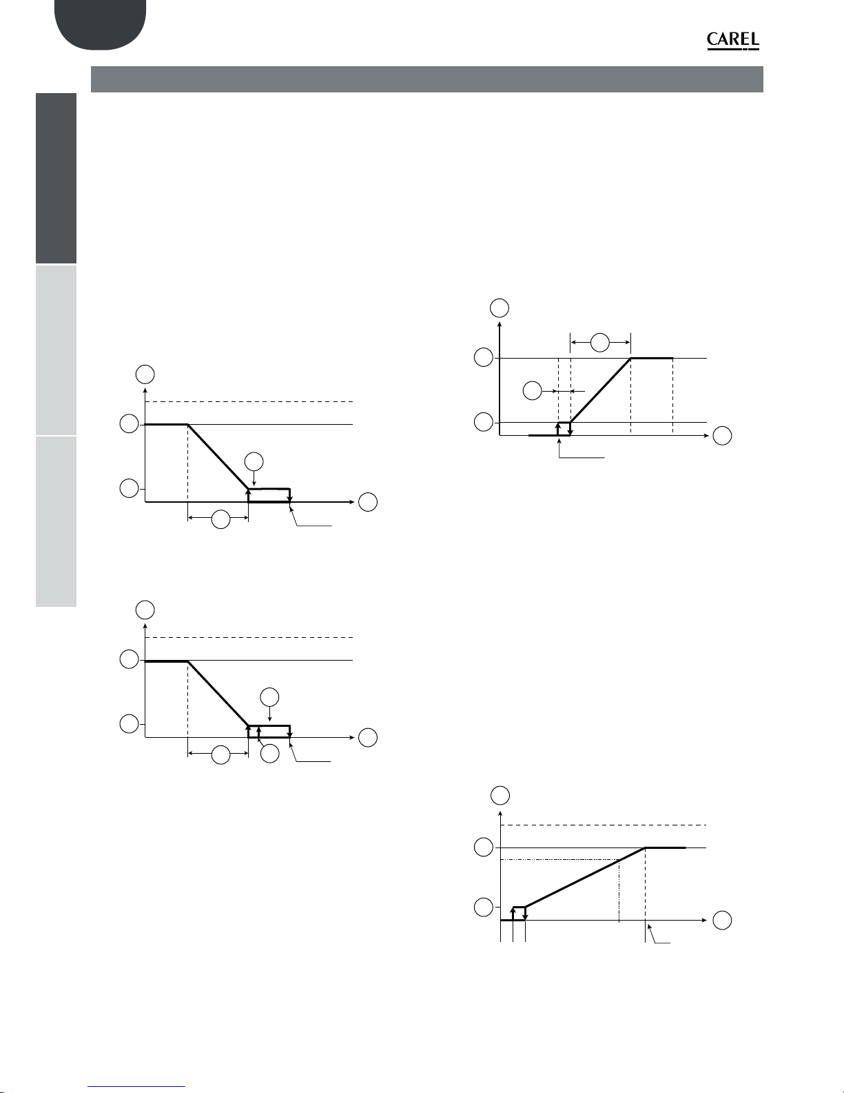
24
ENG
“humiFog multizone - pumping unit” +0300066EN - rel. 1.2 - 10.12.2015
installeruserservice
7. CONTROL
The electronic controller fitted in the humiFog features different control
algorithms, which can be selected from the installer menu.
• HH control:
modulates the capacity (water flow-rate) using two humidity probes, one
control probe normally installed in the AHU in the return air, and one limit
probe, usually installed downstream of the droplet separator.
• HT control:
modulates the capacity (water flow-rate) with two probes, one humidity
control probe and one limit temperature probe. This configuration is
recommended for systems in which a certainly humidity level is required
without however excessively cooling the air.
• H control:
like the HH algorithm but without the limit humidity probe;
Below is the diagram of operation using humidity control probes
100%
Set point
1
3
4
2
6
5
Fig. 7.a
The following chart shows the control probes with humidity control with
differential P+I
100%
Set point
1
3
4
2
6
5
7
Fig. 7.b
Key:
1. production
2. humidity control probe
3. maximum production
4. minimum production
5. proportional band
6. hysteresis (10% of “5”)
7. differenziale
• TH control:
modulates the capacity (water flow-rate) with a temperature probe
normally installed in the AHU in the return air, and a limit humidity
probe, usually installed downstream of the droplet separator. In room
applications, both probes are installed so that the temperature and
relative humidity represent the average ambient values (for example, not
near windows or the nozzles where the cooling and humidification effect
do not correspond to the averages in the room)
• TT control:
modulates the capacity (water flow-rate) with a temperature control
probe and a limit temperature probe. This configuration is recommended
for adiabatic cooling systems in rooms where the control probe is usually
installed in the centre of the room and the limit probe at another “critical”
point where the temperature must absolutely not fall below a set limit
value.
• T control:
like the TH algorithm, but without the limit humidity probe;
Below is the diagram of operation using temperature control probes
Set point
C°/F°0
1
3
4
2
5
6
Fig. 7.c
Key:
1. production
2. probe control temperature
3. maximum production
4. minimum production
5. proportional band
6. hysteresis (10% of “5”)
• PH/PT control:
capacity is modulated proportionally to an external control signal and is
limited based on the value measured by the limit temperature or humidity
probe. This is the typical configuration used in humiFog installations
connected to a Building Management System that generates a control
signal;
• P control:
like the PH/PT algorithm but without the limit humidity probe;
Below is the diagram of operation with proportional control.
100%
max
1
2
3
4
5% 5%
Fig. 7.d
Key:
1. production
2. external request
3. maximum production
4. minimum production

25
ENG
“humiFog multizone - pumping unit” +0300066EN - rel. 1.2 - 10.12.2015
installeruserservice
• CH/CT control:
operation in on/off mode, based on a voltage-free external contact (for
example, a humidistat). The capacity will thus be either the maximum
set or nothing, depending on the status of the external contact, and is
limited based on the value measured by the limit probe.
• C control:
like the CH/CT algorithm but without the limit probe;
The HH and TH algorithms are the most commonly-used, and
recommended for humiFog installations.
The limit humidity probe described above is usually set to high values, e.g.
80% rH, so as to limit the maximum moisture in the air introduced into the
duct and into the room. This is especially recommended in installations
where air flow-rate and operating, temperature and humidity conditions,
may change over time and, consequently an additional safety system is
required to prevent the humidifier from over-humidifying the air and, in
the worse case scenario, condensing in the ducts downstream.
Below are the two diagrams of operation with humidity or temperature
probes
100%
Set point
1
3
4
2
6
5
Fig. 7.e
Key:
1. production
2. limit probe
3. maximum production
4. minimum production
5. proportional band
6. hysteresis (10% of the set point)
N.B.: for convenience, the diagrams show continuous modulation of
the flow-rate while, depending on the model, control may be
continuous or in steps.
7.2 Evaporative Cooling
If optiMist is used as an application dedicated to evaporative cooling, the
possible controls are:
• TT Control
• TH Control
• TF Control
• T Control
• PH/PT/PF Control
• P Control
• C Control
• CH/CT/CF Control
IMPORTANT: All of these controls require a consent signal that lets the
humidifier know when it can operate. This indication corresponds with
the activation of the recovery unit in the Air Treatment Unit (ATU); this
information can be sent to the humidifier through:
• a modulating 0-10V signal (corresponding to the opening of the
renewal air locks) or
• a digital contact or
• a digital variable via supervision (DIG 63).
A delay in the humidifier activation can be set, starting from the activation
signal from the recovery unit previously described.
T CONTROL
This type of control consists of a Proportional+Integral type control of the
temperature detected by a probe located in the return air, downstream
from the exchanger.
The proportional action will allow for the control of the flow-rate as a
function of the distance between the temperature detected and the
setpoint. The integral action, on the other hand, will act on the reaction
speed of the system.t. L’azione integrale, invece, agirà sulla velocità di
reazione del sistema.
Grafico 1
Temp.
Fatt.P
SET
SET
+ ∆
Band
Hyst=10%Band
Fig. 7.f
As seen in the figure, increasing factor P (dashed red line) reduces
sensibility to temperature variations, resulting in a decreased reduction
request in correspondence to the same temperature variation. The
integral contribution, on the other hand, reduces the request to a greater
extent the longer the deviation from the control temperature setpoint
remains.
• controllo TH:
This type of control is used to modulate the capacity (water flow-rate)
with a temperature probe, installed in the return air, downstream from
exchanger, an a limit humidity probe, usually installed downstream from
the droplet separator.
In order to enable this configuration, a droplet separator is NECESSARY,
otherwise there is a risk that the probe could get wet, thus constantly
detecting humidity values close to the saturation point.
The humidity probe will further limit the maximum request.
TT CONTROL
This type of control is used to modulate the capacity (water flow-rate)
with a temperature control probe and a temperature limit probe. The
control probe is usually installed in the centre of the room and the limit
probe in another “critical” point where the temperature must absolutely
not be lower than a settable limit value.
TF CONTROL (T + air flow/flow-rate limit)
This type of control is used to modulate the capacity (water flow-rate)
with a temperature control probe and an air flow modulator, which can
correspond to:
• the modulating opening signal of the recirculation air lock;
• the modulating signal from the fan
In this case, the limit signal will function as:
• a temperature limit signal, in the event of a modulating signal from
the fan
• a humidity limit signal, in the event of a air lock opening modulating
signal.
PH/PT/PF CONTROL
The modulation of the capacity is proportional to an external control
signal and limited based on the measured value of the temperature,
humidity or flow limit signal.
This is the typical configuration when the control is entrusted to a
Building Management System that generates a control signal.

26
ENG
“humiFog multizone - pumping unit” +0300066EN - rel. 1.2 - 10.12.2015
installeruserservice
• P Control
This control is like the PH control, but without humidity limit probe.
The following is a graphic with proportional control.
100%
max
1
2
3
4
5% 5%
Fig. 7.g
Key:
1. production
2. external request
3. maximum production
4. minimum production
• CH/CT/CF control
This control mode corresponds to the ON/OFF operation, from a nonpowered external contact (for example, a humidistat).
The capacity will therefore be the maximum set or nothing (no
modulation) according to the status of the external contact and limited
based on the limit signal.
See sections TT/TH/TF for more information regarding limit signals.
• C control
This control corresponds to the ON/OFF operation mode without any
limit probe. The request directly follows only the control contact.
Note: Whenever the activation signal from the recovery unit is a
digital signal, the control contact will NOT be the same signal; they will be
two distinct signals.
• Limit probe
In the following graphics, the first represents the limitation of the
maximum production with a temperature limit probe or an activation
signal from the IEC ventilator. The second graphic, on the other hand,
represents the case in which the limit probe is a humidity probe or an
opening signal from the recirculation air lock.
H=10%Band
Band
SET °C/°F
% Fan
Y
Fig. 7.h
H=10%Band
Band
SET %RH or
% Opening
Y
Fig. 7.i

27
ENG
“humiFog multizone - pumping unit” +0300066EN - rel. 1.2 - 10.12.2015
installeruserservice
8. SINGLE ZONE AND MULTIZONE CONFIGURATION
The humiFog system can be used in the following configurations:
8.1 Single zone
For humidification and/or cooling applications in AHUs or industrial
environments. The pumping unit has just one distribution system, a rack
in the case of AHUs or a room distribution system with simple manifolds
and nozzles or blower units. The humiFog control system (single zone
version UAxxxxxxxx) controls both the pumping unit and the connected
distribution system. In particular, it receives signals from the probes and/
or the external control system, calculates the required humidification/
cooling capacity, starts the pump to pressurise the water and manages
the solenoid valves in the distribution system. In addition, it manages the
filling, wash and drain cycles.
Single zone application in AHU
As can be seen in the figure, humiFog is a complete system for
humidification/cooling in AHUs.
humiFog can be set for:
- capacity/flow-rate control:
As described in detail in the paragraph “humiFog with flow control”, the
humiFog controller managers the humidification and/or cooling capacity
by controlling the water flow-rate atomised continuously across a wide
range of modulation.
The outlet pressure is kept within the optimum water atomisation limits
by the range of modulation of the pump speed and control of the
number of nozzles that atomise the water.
For example, if low capacity is required, only the first group of nozzles is
activated and the pump speed will be controlled to ensure the required
capacity (Fig. 8.a point 1). If the request increases, the pump speed will
increase and, as a consequence, the flow-rate and outlet pressure will
increase. If the pressure exceeds the maximum limit (75 bars, settable)
humiFog will activate a further group of nozzles (max 4 groups), Fig. 8.a
point 2, so that, for the same flow-rate, the operating pressure will drop
and fall within the limits (25-75 bars, settable). If the request increases
further, the pump will increase the flow-rate and the pressure until
activating a further, third, group of nozzles (Fig. 8.a point 3). The process
is repeated until the maximum flow-rate is reached, corresponding to
all the groups of nozzles being active and the pump operating at the
maximum rack flow-rate (Fig. 8.a point 4). Similarly, the system will behave
in reverse if the request decreases, reducing the speed and consequently
the flow-rate of the pump and deactivating the groups of nozzles one
after the other.
The groups of nozzles on the rack are configured automatically during
humiFog system selection procedure using the “humiFog excel tool”
and is described in detail in the documents supplied with the water
distribution system (rack).
The flow control configuration guarantees maximum precision
of humidification and adiabatic cooling as capacity is controlled
continuously and across a wide range.
- constant pressure control:
As better described in the paragraph “humiFog with constant pressure”,
humiFog is fitted with an inverter to control the speed of the pump, so
as to maintain the pressure at the rated value set by parameter, typically
70 bars.
bar
20
bar
20
80
70
50
30
10
0
0
20 40 60 80 10 0 120 14 0 16 0 180
bar
kg/h
60
40
20
38%25%
58%38%25%17%
17%
25%17%
100%
2
3
4
80
70
50
30
10
0
0
20 40 60 80 10 0 120 14 0 16 0 180
bar
kg/h
60
40
20
80
70
50
30
10
0
0
20 40 60 80 10 0 120 14 0 16 0 180
kg/h
60
40
80
70
50
30
10
0
0
20 40 60 80 10 0 120 14 0 16 0 180
kg/h
60
40
17%
1
Fig. 8.a
The water distribution system/systems have nozzles organised into
groups, called steps, which in general each have different capacities.
Based on the flow-rate of water to be atomised in one or more zones,
the humiFog system will activate the best combinations of steps until
the nozzles atomise the required quantity of water. For example, if the
system has three steps with the following capacities: step 1 - 30kg/h, step
2 - 30kg/h; step 3 - 20kg/h, and the request is 30 kg/h, then step 1 is
activated, if the request is 50 kg/h then step 1 and step 3 are activated,
while if the request is 60 kg/h then step 1 and step 2 will be activated.
In AHU applications, it is useful to suitably distribute the capacity of the
steps so as to allow good resolution of capacity modulation. For example,
a humiFog with a 180 kg/h rack, using 4 modulation steps and 4 kg/h
nozzles, may have steps with the following capacities:
step 1 96kg/h
step 2 48kg/h
step 3 24kg/h
step 4 12kg/h
Note that the resolution is 12/180=6.6%, therefore very good, with just 4
modulation steps!
The technique involves assigning around half of the capacity to one step,
half of this to the next step, half of the latter to the following step and so
on, according to the following formula:
S=
M
t2
T-1
2N-1
With:
S= capacity of step T
M= rack capacity
T= index of the step, 1 to N
N= step number
N.B.: the maximum flow-rate of one step is 120 l/h.

28
ENG
“humiFog multizone - pumping unit” +0300066EN - rel. 1.2 - 10.12.2015
installeruserservice
Obviously, the capacity calculated above should be rounded off based on
the capacity of the nozzles (in this example, 4 kg/h), the number of nozzle
manifolds that can be installed, etc.
Each zone may have up to 6 modulation steps.
The groups of nozzles are normally configured when selecting the
humiFog system, and the procedure is clearly described in the documents
supplied with the water distribution system (rack or room distribution
and atomisation system).
Single AHU application
1
2
MASTER CABINET
3 4
5
6 7
Fig. 8.b
Key:
1. water from REVERSE OSMOSIS system;
2. atomising nozzles;
3. vent valve;
4. water fill valve;
5. water drain;
6. main drain valves;
7. high pressure stainless steel or rubber hoses.
Single zone room applications
As can be seen in the figure, humiFog is a complete system for
humidification directly into rooms.
As better described in the paragraph on “humiFog with constant pressure”,
humiFog features an inverter to control the speed of the pump, so as to
maintain the pressure at the rated value set by parameter, typically 70 bars.
Note that in the case of humidification and/or cooling adiabatic directly
into rooms, constant pressure control is preferred over flow control: as
the droplets are atomised directly into the environment, to minimise the
space required for evaporation, the smallest possible diameter should
be achieved and therefore the water must be atomised at maximum
pressure. This is represented by constant pressure control, which
maintains the pressure at 70 bars.
The water distribution system/systems have nozzles organised into
groups, called steps, which in general each have different capacities. For
simple installation and operation, however it is recommended to use
steps of the same capacity. For example, a 100 kg/h system may have
two 50 kg/h steps, where necessary made up of two or more lines with
nozzles/blower units. Based on the flow-rate of water to be atomised,
the humiFog system will activate the steps required for the nozzles to
atomise the necessary quantity of water. The zones can have up to 6
modulation steps. humiFog also manages rotation of the lines, emptying,
washing etc, better described in the following paragraphs.
The groups of nozzles are normally configured when selecting and sizing
the humiFog system.
Single room application
1
2
MASTER CABINET
3
4
5
6
7
8 9
Fig. 8.c
Key:
1. water from REVERSE OSMOSIS system;
2. air inlet;
3. drain valves;
4. ambient probe;
5. fill valves;
6. blower;
7. main drain valves;
8. high pressure stainless steel or rubber hoses.
8.2 Multizone application in AHU or room
For standard humidification and/or cooling applications in AHUs or
industrial environments.
The humiFog controller manages the water pressure generated so as to
keep it at a constant level, typically 70 bars.
As illustrated in the following figure, the pumping unit has a distribution
system, a rack in the case of AHUs or a room distribution system with
simple manifolds and nozzles or blower units. The humiFog control
system (multizone zone version UAxxxxxxxx) controls both the pumping
unit and the connected distribution system. All the other zones, whether
an AHU or an industrial environment, has a zone control cabinet fitted
with electronic controller that manages its own distribution system, a rack
in the case of AHUs or a room distribution system with simple manifolds
and nozzles or blower units. In addition, it communicates with the Master
for all the common system procedures, such as washing, emptying,
etc. Each cabinet, both Master and Slave, receives the signals from the
probes and/or the external control system, calculates the required
humidification/cooling capacity and, when the water has reached the
rated pressure, manages the solenoid valves in the distribution system to
generate the required capacity.
Constant pressure control rationalises operation of the humiFog pumping
unit as, despite the lower precision of stepped modulation, it can treat a
number of zones at the same time without installing a pumping unit for
each AHU or industrial environment.
For the configuration of the steps, see the instructions provided in the
previous paragraph “Single zone applications in AHUs – constant pressure
control” and “Single zone applications in rooms”.
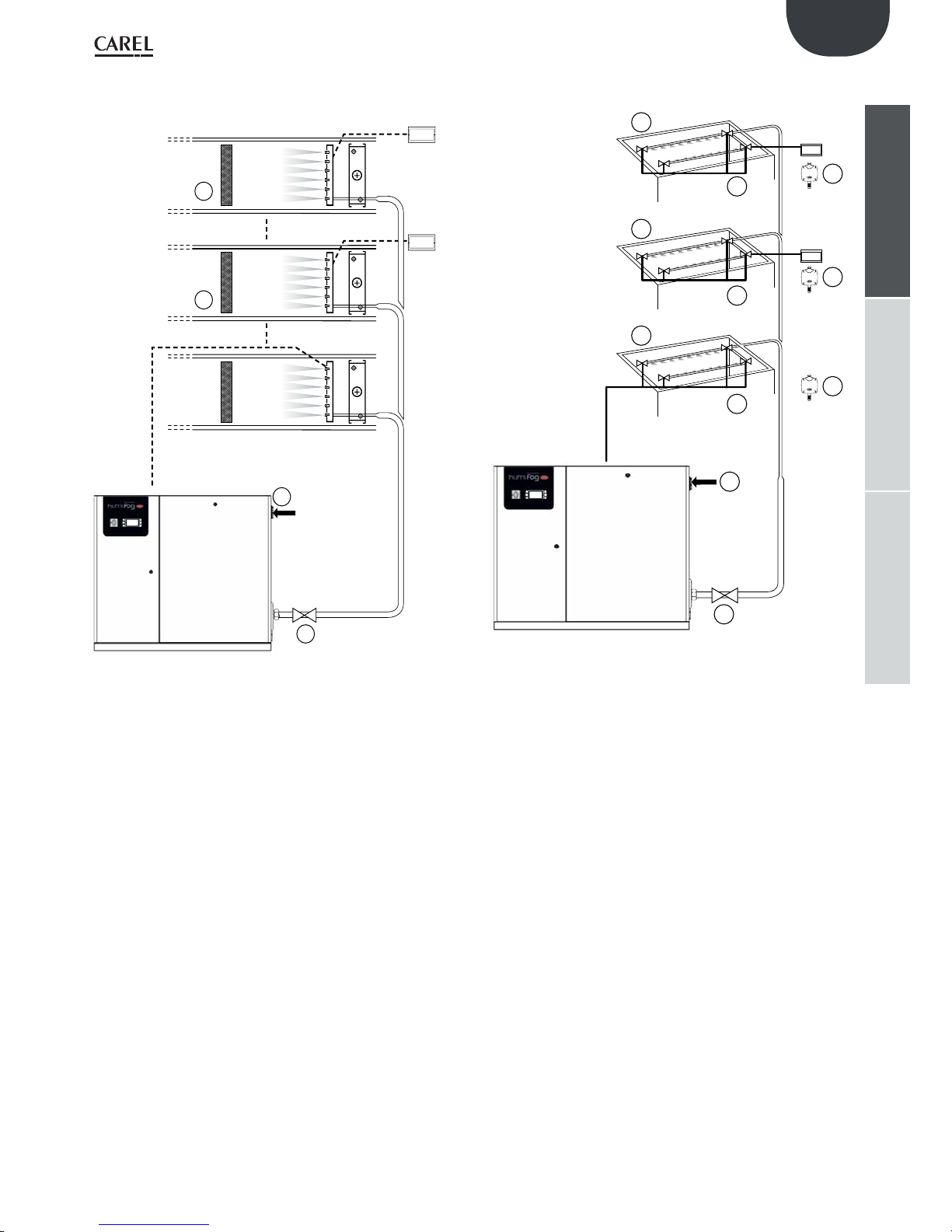
29
ENG
“humiFog multizone - pumping unit” +0300066EN - rel. 1.2 - 10.12.2015
installeruserservice
Multi-room application
1
2
3
3
4
4
4
5
3
2
2
MASTER CABINET
SLAVE
CABINET
SLAVE
CABINET
Fig. 8.e
Key:
1. water from REVERSE OSMOSIS system;
2. drain valves (one in each zone);
3. fill valve;
4. ambient probe;
5. main drain valve.
Multi-AHU application
1
2
2
2
3
MASTER CABINET
RACK
SLAVE
CABINET
SLAVE
CABINET
RACK
RACK
Fig. 8.d
Key:
1. water from REVERSE OSMOSIS system;
2. air handling unit;
3. main drain valve

30
ENG
“humiFog multizone - pumping unit” +0300066EN - rel. 1.2 - 10.12.2015
installeruserservice
8.3 Indirect adiabatic cooling applications
One important function involves indirect adiabatic cooling applications
(summer): a pumping unit can cool the exhaust air before it enters a
heat recovery unit. This function is often complementary with the use of
humiFog for air humidification in winter. The configuration in question is
illustrated in the figure.
The system can be configured in two ways:
• capacity/flow-rate control: just one rack at a time atomises the water,
with continuous system capacity control and consequently maximum
precision. See paragraph “4.1 Pumping unit with flow control
configuration” for further information on capacity control.
• constant pressure control: two racks can atomise the water at
the same time or individually. This maximises energy saving by
simultaneous indirect (cooling the air before the heat recovery unit)
and direct adiabatic cooling (cooling the air before this is introduced
into the environment), however with less precise control (stepped
capacity modulation, see paragraph “4.2 Pumping unit with constant
pressure control” for further information on capacity control).
For example, an indirect system with 100 kg/h of water sprayed can
cool the exhaust air with an equivalent cooling capacity of 68 kW; this,
in the heat exchanger/heat recovery unit, will cool the fresh air with an
equivalent cooling capacity of 34 kW, for a power consumption of just
1.2 kW! In addition, this reduces the capacity required of the cooling
coil and the chiller. For a detailed and complete description, see “Air
humidification” by Lazzarin - Nalini, chapter 11.
Indirect and direct adiabatic cooling
1
HE
7
2
3
4
5
6
Fig. 8.f
Key:
1. recirculated air;
2. exhaust air;
3. saturated and cooled air;
4. outside air inlet;
5. heated exhaust air;
6. cooled outside air;
7. fresh air.
8.4 System operation
humiFog multizone independently manages the production of
pressurised water, the distribution and filling, drain and wash cycles. This
paragraph illustrates the latter functions.
Filling: before starting the production/atomisation phase, the piping
must be filled with water and, then, vented of air. This ensures correct
pressurisation of the lines and minimises the possibility of pressure
swings due to air trapped in the piping. The system is empty when first
started and following draining due to extended inactivity (see the rest
of the paragraph for further information). Before starting production, the
system is filled by starting the pump, which generates the rated capacity
of the pumping unit and fills the piping with water for a time set by
parameter. This time must be established by trial and error when starting
the system. When filling, all the capacity-control and drain valves in all
the zones are open, while the vent and main drain valves are closed. The
distribution system must be sized so that, in these conditions, the water
pressure does not exceed 5 bars, thus avoiding situations where the
nozzles atomise/spray water (each nozzle contains a valve that prevents
atomisation at pressures below 7 bars).
Washing: this is performed periodically and involves flushing water
through the piping for a time set on the menu. The purpose is to
completely wash the system and avoid stagnation of water. It is performed
in the same way as filling, but lasts longer: the time should be set so
that the water used for washing is at least 3 times the volume of water
contained in the complete installation. The wash cycle is performed every
day at the same time (e.g. every day at 4 in the morning) or periodically
at an interval set by parameter. At the end of the first wash cycle, the
system remains full, while, starting from the second consecutive wash
cycle without operation, the installation will be left empty. In addition, a
wash cycle is also performed at start-up.
If the wash cycle is disabled, then the system will be left empty after a
period, set by parameter, during which it has remained full and without
operation.
Pressure relief: this last function is used to save water and limit the
filling and emptying cycles, without affecting the hygiene features of the
system, nor its performance.
The pressure relief function, when a branch (piping with nozzles or blower
units) is disabled (stops atomising), the capacity-control valve is obviously
closed and the drain valve is opened. The latter, however, will be closed
again a few seconds later so that the pressure falls below 7 bars (and
then the nozzles no longer spray) however the branch remains almost
completely full of water. This avoids emptying the branch (saving water)
and having to fill the system when production is required again in the
branch. Note that opening the drain valve is required to achieve a rapid
decrease in pressure from 70 bars to virtually 0, preventing the nozzles
from spraying water at intermediate pressure values and generating large
droplets that would wet the AHU/room.
Clearly, it is recommended to enable pressure relief. Indeed, thanks to the
emptying procedure described above, in this case too there will not be
stagnation of water in the piping for a time greater than the set value.
Rotation (only if “Pressure relief” is enabled): in constant pressure systems,
humiFog periodically “rotates” the branches (piping with nozzles or
blower units) that atomise the water. For example, if the zone has four
branches and only two are in production, then the first and the third will
be activated, for example, for 20 seconds, and then deactivated; at the
same time, branches two and four will be activated. After a further 20 s,
branches two and four will be deactivated (with pressure relief), and one
and three will be activated simultaneously. The example in the diagram
with six branches gives a better idea: this shows an activation sequence
where each configuration (row) lasts 20 s. “A” indicates the active branch,
“d” the inactive branch:
t=0
A
dd
A
dd
t=20s d
A
dd
A
d
t=40s d d
A
dd
A
t=60s
A
dd
A
dd
t=80s d
A
dd
A
d
t=100s d d
A
dd
A
Rotation is feasible if system operates with constant pressure and all the
branches have the same rated capacity. Obviously, pressure relief must be
enabled, otherwise each rotation would require a filling cycle.

31
ENG
“humiFog multizone - pumping unit” +0300066EN - rel. 1.2 - 10.12.2015
installeruserservice
8.5 Constant pressure systems: notes on
capacity control
In constant pressure systems, humiFog keeps the pressure at the desired
value when the required capacity changes (that is, the sum of the
capacities required by each zone).
Capacity required increases: whenever a zone requires an increase in
capacity, the pumping unit does not respond immediately: the flowrate/capacity of the pump is modified to generate the required capacity
and only then is the signal sent to the zone, which suitably controls the
solenoid valves (overboost cycle). For example, if a zone has 4 branches,
25 kg/h in each branch, two branches are active and the request
increases to 75 kg/h, then the zone controller sends the request to the
pumping unit, which increases the flow-rate to 75 kg/h and, only when
this has been reached, sends the signal to the zone to activate the third
branch and consequently spray 75 kg/h. In the delay until the signal is
received, the water pressure rises above the pressure set point, however
this guarantees that, when the third branch is activated, the pressure will
not fall below the required value and cause the nozzles to spray coarse
droplets. During this transient period, the excess water is recirculated
by the bypass valve. Subsequently, when the zone is in the final status
(solenoid valves suitably activated, third branch open, as in the example)
the water pressure drops for a few seconds to around 60 bars, to ensure
complete closing of the bypass solenoid valve (underboost cycle).
Capacity required decreases: in this case, the pumping unit responds
immediately to the request from any one of the zones to decrease the
capacity. As a consequence of the reduction in atomised water in the
zone/zones, the pressure will increase and the bypass valve may be
activated. There will also be a reduction in the pump rotation speed (to
reduce the flow-rate to the new value required by the zone) and, if the
bypass valve has been activated, an underboost cycle will be performed
(see the description above).
In the general case where there are multiple zones that require variations
in capacity, these will be satisfied one at a time, in order, and only at
the end of the last variation will the underboost cycle be performed, if
necessary.

32
ENG
“humiFog multizone - pumping unit” +0300066EN - rel. 1.2 - 10.12.2015
installeruserservice
9. START UP
Before starting the humidifier check:
water and air connections (chap. 2). In the event of water leaks do not
start the humidifier before having resolved the problem;
electrical connections (cap. 3)
9.1 Starting
1
0
ON
9.2 Stopping
1
0
OFF
Note: if the system is stopped for an extended time, open the
valve at the end of the water line to assist drainage. If the system is fitted
with drain solenoid valves at the end of the line (optional), this is done
automatically.
9.3 First start-up
HumiFog is fitted with a guided procedure for the first start-up, which
guides the user step by step on how to set the humidifier. The first screen
is dedicated to language, as shown in the following screen
Press ENTER to select the desired language. Once finished press ESC to
return to the startup procedure. This screen is displayed for 60 seconds.
Successively, a series of “wizard” screens shall appear, which will guide the
user on fillig-in all the parameters required for the proper setting of the
humidifier
• YES: the screen for selecting the language displays at the next start-up
of the humidifier;
• NO: the screen for selecting the language does not display any more
at start-up.
Note: the language can be changed at any time by following the
instructions in Chapter 9.7 Installer menu.

33
ENG
“humiFog multizone - pumping unit” +0300066EN - rel. 1.2 - 10.12.2015
installeruserservice
10.1 Keypad
1
2
4
6
5
3
Ref. Function
1 alarm list active alarms and reset any alarms present
2 PRG
from the “main” screen, access the main menu
3 ESC return to the previous screen/display
4 UP circular navigation inside the menus, the screens, the parame-
ters and the values of the parameters
from the “main” screen, access an “INFO menu”
5 ENTER select and confirm (like the “Enter” key on a computer keyboard)
from the main screen, access the “SET” screen
6 DOWN circular navigation inside the menus, the screens, the parame-
ters and the values of the parameters
from the main screen, access the “ALARM HISTORY” screen
10.2 “Main” screen
6
5
7
1
2
3
4
8
9
Ref.
Function
1 description of the area status:
“OFF” state area
“IN Function” state area
“READY” state area (is in standby)
“WASHING” state area
“FILLING” state area
The descriptions of the missing areas are grouped in the supervision
table
2 value read from the main control signal
3 limit probe reading (if enabled)
4 pump state:
• pump in Function (the triangle in the center of the icon flashes);
• pump not in Function (the triangle in the center of the icon does not
flash, empty);
5 Access to the “INFO” screen (UP key)
6 Access to the “SET” screen (ENTER key)
7 Access to the “HISTORY ALARM” screen (DOWN key)
8 State of spray nozzles:
• spray nozzles in Function
• spray nozzles not in Function
• disabled area
9 Time frame in “ACTIVE” state
10.3 “INFO” screens
Series of read-only screens for displaying the main humidifier status
values. To access, press UP from the “Main” screen. There are four “INFO”
screens; to move from one screen to the next, press UP or DOWN.
Press ESC to return to the “Main” screen.
1. INFO screen - Information area (read-only)
5
1
2
3
4
Ref.
Parameter and UM Status
1 Request [kg/h]
2 Production [kg/h]
3 AUX Probe (if enabled)
4 Valve state:
Refill valve F
Drain valve D
Ventilation V
”A” Opened (atomizing branch); “ - “ closed
”?” Opened (drain branch) ; “. - ” closed
”B” Opened (in ventilation); “ - ” closed
5 Date and hour
2. INFO screen - Remote information area (read-only)
Indicates the current status of each remote location connected to the cabinet
• Off to flow state
• In production
• No request
• Etc...
3. INFO screen - Pump information (read-only)
1
3
5
2
7
4
6
Ref.
Parameter and UM Status
1 Request [kg/h] Represents the total requests of each area
2 Pump pressure [bar] Pressure generated by the pump
3 Conductivity [µS/cm] Conductivity measured at the inlet of humiFog
4 Pump hours [h] Hours of operation occurred since the last reset
of the hour meter
5 Total hours [h] Total hours of operation only
6 Bypass temp. [°C/°F] Temperature of the water recycled in the pump
7 Rack temp. [°C/°F] Temperature detected by the probe in the ato-
mization area (optional). Setpoint set from CTA
10. USER INTERFACE

34
ENG
“humiFog multizone - pumping unit” +0300066EN - rel. 1.2 - 10.12.2015
installeruserservice
10.4 “SET” screen
Used to set the main values for the humidifier.
From the main screen press:
• ENTER to access the menu;
• ENTER to select the parameter you want to set;
• UP and DOWN to modify the value of the selected parameter;
• ENTER to confirm and go to the next value.
1
3
5
2
4
Ref.
Parameter and UM Status
1 Enabling the pump set [Yes/No] to the no
parameter to completely disable the system
YES
2 Setpoint (T or %rH) [°C/°F or %U.R] represents
the requested humidity or temperature (available if the control is fitted with a probe)
28°C/82°F or 50%rH
3 Auto Operation [Auto/OFF] following the
request of the area; OFF the non-atomized
area even in the presence of a request
Auto
4 Maximum pressure [%] setting of the maxi-
mum production from the area
100 %
5 Proportional band (T or %rH) [°C/°F or %U.R] 5 °C/°F or 5% rH
.... Differential (present only if P/I) 2 °C/°F or 5% rH
1
2
Ref. Parameter and UM Default
1
Limit probe setpoint (T or %rH) [°C/°F or %U.R] 10°C/50°F or 90 %rH
2
Limit probe proportional band 5 °C/°F or 5% rH
10.5 ”Alarm History” screen
The alarm history screen displays the messages generated by warnings or alarms
that are solved.
1
2
Ref.
Parameter
1 number, hour and date of warning/alarm
2 Description of warning/alarm
10.6 “Main” Menu
To access press PRG from the main screen
Buttons:
• UP and DOWN: navigation inside the submenus, screens, and range of
values and settings;
• ENTER: confirm and save the changes made;
• ESC: to go back (pressed more than once returns to the “Main” screen)
•
Menù 1° level 2° level Indexing
A. User a. Alarm Threshold -- Aa01
b. Clock -- Ab01...2
c. Sched uler -- Ac01...2
B. Installer a. Pump setup a. Pump setup Baa01...2
b. Water supply Bab01...2
c. Special functions
Bac01...6
b. Zone setpu a. Configura-
tion
Bba01...6
b. Distr. system
Bbb01...3
c. Special
funct.
Bbc01...10
d. Supervisor Bbd01...2
e. External
allarms
Bbe01
c. Remote zones Remote zones Bc01
d. Change Language Language Bda01...2
C. Ma intenance a. System config -- Ca01...2
b. Unit info -- Cb01...3
c. Probe readings -- Cc01
d. Manual request -- Cd01...11
e. Unit Status -- Ce01
f. Working hours -- Cf01...2
g. Alarm log -- Cg01
10.7 “User” Menu
From the main screen press:
• PROG to access the main menu;
• ENTER to select and access the selected menu;
• UP/DOWN to move between the submenus;
• ENTER to enter the submenus
• ENTER to select the parameter and move between the parameters;
• UP/DOWN to modify the parameter;
• ENTER to confirm selected parameter and go to the next parameter;
• ESC to return to the previous menu.
To navigate inside the screens:
• UP or DOWN to modify the value (within the options/range),
• ENTER to confirm and move the cursor to the next value
• ESC to return to the installer menu.

35
ENG
“humiFog multizone - pumping unit” +0300066EN - rel. 1.2 - 10.12.2015
installeruserservice
User Menu Screens:
Menù 1° level 2° level Indexing
A. User a. Alarm Threshold -- Aa01
b. Clock -- Ab01...2
c. Sched uler -- Ac01...2
Submenu: a. 01 Alarm thresold
1
2
3
Ref. Display Description Range Default Unit
Main
1
Alarm-high
Alarm threshold for high
humidity or temperature
0...100
o
-20...70
100
o
40
U.R.
o
°C
2
Alarm-low
Alarm threshold for low
humidity or temperature
0...100
o
-20...70
0
o
20
U.R.
o
°C
Limits
3
Alarm-high
Alarm threshold for high humidity or temperature limits
0...100
o
-20...70
100
o
10
U.R.
o
°C
4
Alarm-delay
Minutes beyond which the
alarm is triggered
0...99 1 min
Submenu: b. Clock
b. Clock 01 CLOCK
Day, date and hour setup
1
2
3
4
Ref. Display Description Range
1
Giorno
Setting the week day Monday to Sunday
2
Formato data
Setting the European or American date format
dd/mm/yy - mm/dd/yy
3
Ora
Setting the hour 0 - 24
Data
Setting according to date
format
b. Clock 02 Clock
Gestione ora solare/legale
1
4
3
2
Ref. Display Description Range
1
Ora legale
“ENABLE”, defines the automatic
switching between standard time
and daylight saving time
Enable/disable
2
Transition
time:
Determine the number of minutes
by which the clock will be adjusted
during the activity time of the transition.
-60 min
3
Start
Defines the start of the daylight
saving time period
4
End
Defines the end of the daylight
saving time period
Same type of setting and requested for the end transition threshold.
This is expressed relatively, not based on the number of days but on the
day of the week.
Setting this parameter requires entries in four different fields:
• Week selection (available options: First, Second, Third, Fourth, Last):
• Day selection;
• Month selection
• Transition start time
The same type of setting is required for the transition end threshold
Note: the default configuration includes changing the standard
time/daylight saving time according to the European standard and the
UTC +1 time zone
Submenu: c. Scheduler
c. Scheduler 01 SCHEDULER
Enabling the scheduler (operation time frames)
1
Ref. Display Description Range Default Unit
1
Enable
scheduler:
Abilita/
disabilita
Note:
• if the unit is configured with the “On/Off” setting or the “Proportional
external signal”, the scheduler manages the switching on and off of
the unit, while the actual regulation is delegated to the external signal:
• if the unit is in “Off by scheduler” the request from the external signal is
ignored, while it is satisfied if the unit is placed in “On” by the scheduler.
Scheduler settings (operation time frames)
1
2
3
5
4
Ref. Display Description Range Def. Unit
1
Day
Setting day of the time frame
2 Enable/disable the time frame
3
00:00
Start hour of time frame ora
4
ON+SET
Type of time frame ON
ON+SET
OFF
5
00.0%
Setpoint of the humidity or temperature frame (editable only for “ON+SET”
frames)
% rH
%T

36
ENG
“humiFog multizone - pumping unit” +0300066EN - rel. 1.2 - 10.12.2015
installeruserservice
Note:
It is possible to set up to 6 time slots in each day of the week to define
ON/OFF and setpoint changes over 24 hours, as follows:
ON: The unit is ON and the production works respecting the current
request (in the case of adjustments in temperature or humidity setpoint
is used in the mask “Set”)
ON+SET (only regulation in humidity or temperature): The unit is ON
following the setpoint defined in the mask of the scheduler.
OFF: The unit going in “Off by scheduler”: each production request isn’t
consider and there is no production.
Note: reffering to the mask Scheduler AC02 below:
The humidifier is in “Off” mode from 0:00 to 10:00 am
At 10:00, the humidifier is in ON mode and works with setpoint equal to
global setpoint (editable in mask “Set” and reported in mask “scheduler”
AC02)
At 15, the humidifier is always in ON mode and works with a setpoint
other than the global 20% rH
At 23:00 the unit is turned off.
10.8 “Installer” Menu
From the main screen press:
• PRG to access the main menu;
• DOWN to move to the installer menu;
• ENTER to move to the password;
• UP/DOWN to enter the password “77“
• ENTER to access the selected menu;
• UP/DOWN to move between the submenus;
• ENTER to select the parameter and move between the parameters;
• UP/DOWN to modify the parameter;
• ENTER to confirm the selected parameter and go to the next parameter;
• ESC to return to the previous menu.
To navigate inside the screens:
• UP or DOWN to modify the value (within the options/range),
• ENTER to confirm and move the cursor to the next value
• ESC to return to the installer menu.
The installer menu is divided into four submenus:
Menù 1° level 2° level Indexing
B. Installer a. Pump setup a. Pump setup Baa01...2
b. Water supply Bab01...2
c. Special functions
Bac01...6
b. Zone setpu a. Configura-
tion
Bba01...6
b. Distr. system
Bbb01...3
c. Special
funct.
Bbc01...10
d. Supervisor Bbd01...2
e. External
allarms
Bbe01
c. Remote zones Remote zones Bc01
d. Change Language Language Bda01...2
Submenu a. Pump setup
a. Pump setup - Pump setup
1...2
Contains the menu with the installer parameters related to the pump
station
Pump operation mode
1
2
Define the type of operation of the pumping station - between constant
pressure (the atomization occurs when the pressure is set constantly, set
the pressure to 70 bar) and flow control, the atomization starts at 25 bar
and increases to 70 bar. If the humidity setpoint is not reached at this
point, then the next branch is opened, atomizing again between high
and low pressure, which are the only two parameters to be set. In the case
of a multi-area system, the only possible option is the constant pressure
setting.
Constant pressure
Ref. Display Description Default Unit
1 Mode
Set to constant
pressure
PC per i codici
UA...ZD....
CP per i codici
UA...HD....
2 Pressure set
Pressure at which
the atomization
occurs
70 bar
Flow control
Ref. Display Description Default Unit
Mode
Set to flow control PC per i codici
UA...ZD....
CP per i codici
UA...HD....
High pressure
Activation value
of the next rack
branch
70 bar
Low pressure
Deactivation value
of the rack branch
25 bar
Change pump
1
Ref. Display Description Default Unit
1 Change pump?
Activity to be performed only
when the pump is replaced,
in order to reset the operating hours and the warnings
related to them
No
If it is necessary to replace the pump, it is required to set the parameter
to “YES” by resetting the hourmeter from the first 50 hours of operation
If it is necessary to replace the pump assembly, it is of fundamental
importance to signal the replacement on the Baa02 screen, in order to
reset the parameters related to the operation of the pump and have the
correct maintenance and oil change alerts, particularly that relating to
the first 50 hours of operation, which is not restored following the simple
reset of the hourmeter on the Cf02 screen.

37
ENG
“humiFog multizone - pumping unit” +0300066EN - rel. 1.2 - 10.12.2015
installeruserservice
Submenu a. Pump setup
a. Pump setup b. water supply 1...2
Water alarm settings
In the menu you will find two screens that define the parameters of water
supply and the relative signal delay of any warnings
1
2
Ref. Display Description De-
fault
Unit unità
1 Low
pressure
alarm
delay
The time after the locking
alarm is notified, with regard
to the low water pressure
in the pump outlet of the
humidifier, does not exceed
the minimum threshold set by
Carel at 20 bar
0 - 999 45 sec
2 WTS alarm
input
logic
Manages the logic of the
ROAL-G0A contact which
receives the possible alarm
state coming from the water
treatment system. In the event
that an alarm state occurs, this
is also displayed on the cabinet display as “water treatment
plant alarm” The possible
logics are the following:
N.C. means that the alarm
state will occur at the opening
of this contact
N.A. means that the alarm
state will occur at the closing
of this contact
N.C./
N.A.
N.C.
1
2
Ref. Display Description De-
fault
Unit unità
1 Conductivity
warning
threshold
Conductivity value of the
inlet water to the pumping
station beyond which a
warning is triggered. This
threshold does not represent a blocking notification
for the system, but only a
pre-alarm
100 µS
2 Conductivity
alarm
threshold
Conductivity value of the
inlet water to the pumping
station beyond which the
system is blocked. The
value set by the “high conductivity alarm threshold”
parameter must always be
greater than the previous
parameter
200 µS
Submenu a. Pump setup
a. Pump setup c. Special function 1...6
Washing and filling
1
2
Ref. Display Description De-
fault
Unit unità
1 Enable
filling
When the pumping station
should start and detects
that the water discharge line
is empty before start-up,
enabling the pump, seasonal
restart etc. , enabling this parameter with Yes, the pump
dispenses the minimum flow
for a defined time to the
next parameter, in order to
fill the line before the start of
the atomization
Si/No Si
2 Duration
The filling time of the discharge line before starting
the atomization, only if the
discharge line is detected as
being empty
1/60 2 min
1
2
3
Ref. Display Description De-
fault
Unit unità
1 Wash mode:
Periodic
Giornaliero
Solo
svuotamento
Washing performed after
a set number of inactive
hours
Washing performed daily
at a pre-defined hour
Complete emptying of
the lines performed after
a set number of inactive
hours
Perio dico
giornaliero
solo
svuotamento
Perio dico
Tipo
2 Intervallo
Ora
Intervallo
Number of inactive hours
after which the periodic
washing is performed
Time of day when you run
the daily wash
Number of inactive hours
after which the complete
emptying of the lines is
performed
49
0
49
h
h
h
3 Duration
Duration
-
Number of minutes
for which the periodic
washing is performed
Number of minutes for
which the daily washing is
performed
1 - 10
1-1022
-
min
min
-
Note: if the washing parameter was set to “Periodic” or “Daily”, a
washing will be performed at every start of the pumping station.

38
ENG
“humiFog multizone - pumping unit” +0300066EN - rel. 1.2 - 10.12.2015
installeruserservice
2
Ref. Display Description De-
fault
Unit
unità
1 Fill/Wash
pump speed:
As specified on the Bac01
screen, if the filling or washing is
enabled, you have the possibility
to set the nominal flow rate in %
at which the filling and washing
is performed
0...999 14 %
Slowdown pump
1
2
3
Ref. Display Description De-
fault
Unit
unità
1 Slowdown
vent. valve
zone
Defines in which area to open
the ventilation valve during the
slowdown of the pump at the
reached setpoint. This phase is
required because the normal
mechanical inertia of the pump
when reaching the setpoint
could generate a critical pressure
for the next restart
0...6
(Numero della
zona da
aprire)
1
n°
2 Opening
duration
ventilation
valve
Time of opening the ventilation
valve to ensure the correct
pressure of the system at the
next restart
1...15 3 sec.
3 Fill/Drain
valves
Time of opening the drain valves
of the area defined by the first
parameter of the screen to ensure the proper pressure at the
opening of the ventilation valve
1...15 1 sec
Drain-valve status in stand-by
1
2
Ref. Display Description Def. Unit
unità
1 close fill valves
in case of empty
standby for more
than:
Set minutes after which,
if the system detects an
empty standby, stops the
supply towards the load
solenoid valves (N.C.)
0...540 15 min
2 Pump status relay
logic:
Set the relay logic that
represents the state of
the pump through the
free ROEN-COM contact.
Open contact ON pump
(if the set parameter
is N.A., otherwise vice
versa)
Closed contact OFF
pump (if the set parameter is N.A., otherwise vice
versa)
N.A/
N.C.
N.A.
Cooling the water treatment system
In order to preserve the state of the membranes even in limited
environmental conditions (for example temperature) it is possible to
provide the enabling of the successive parameters which run the water
by avoiding overheating
1
2
3
Ref. Display Description Range Default Unit
1 Enable WTS
cooling
procedure
Enables at the end of the
“T. Inactivity” parameter, the
opening of the load solenoid
valve of the pumping station
for a time defined by the “Duration” parameter in order to
activate the water treatment
system to ensure optimal
conditions for maintaing the
membranes
SI/NO SI Tipo
2 Inactivity
thr:
Time after which the system
opens the load solenoid valves of the pumping station
0...999 24 h
3 Duration
Opening time of the load solenoid valves of the pumping
station
0...99 15 min
Submenu b. Zone setup
b. Zone setup a. Input config.1...6
Remote area address
1
Ref. Display Description Range Default Unit
1
Zone address:
Field-bus address of
the area
1 -6 1 n°

39
ENG
“humiFog multizone - pumping unit” +0300066EN - rel. 1.2 - 10.12.2015
installeruserservice
Operating mode (in this regard consult the chapters xxxx)
1
Ref. Display Description Range Default Unit
1
Unit mode
Defines the operating mode of each area
Humidification or D.E.C
I.E.C.: Indirect evaporative cooling with temperature setpoint
Generator of pressurized water: defines a pressure setpoint according to the preset measuring unit. With this operation disable the management of the solenoid
valves of the distribution system and the distribution system in general
Humidification
I.E.C.
Generator of pressurized
water (only to a single area
UA...HD...)
Umidific Tipo
Regulation type
1
2
Ref. Display Description Range Default Unit
1 Regulation type
Set the adjustment type of the atomised water production
Humidity + Lim temp = main humidity probe with temperature limits
Humidity+Lim. Humid. = main humidity probe with humidity limits
Humidity = main humidity probe
ON/OFF+Lim. Temp = humidistat/thermostat + limit temp. probe
ON/OFF = humidistat/thermostat
ON/OFF = humidistat/thermostat + flow limits (only IEC)
Ext. Sign. + Temp. Lim. = analogic signal + limit temperature probe
Ext. Sign. + Hum. Lim. = analogic signal + limit humidity probe
External signal = analogic signal
External signal = analogic signal + flow limits (only IEC)
Temp.+Lim. Temp. = main temperature probe with temp. limits
Temp.+Lim. Humid. = main temperature probe with temp. limits
Temperature = main temperature probe
Temperature = main temperature probe + flow limits (only IEC)
Umidità+Lim temp
Umidità+Lim. Umid
Umidità
ON/OFF+Lim. Temp
ON/OFF
Segn.Ext+Lim.Temp
Segn.Ext+Lim.Umid
Segnale esterno
Temp.+Lim. Temp
Temp.+Lim. Umid.
Temperatura
Umidità+Lim. Umid tipo
2 Reg. logic
P = proportional
P+I = proportional + integral
P
P+I
P tipo
Probe confirguration
Main probe confirguration
1
2
4
3
Ref. Display Description Range Default Unit
1 Main probe
Type of main control signal 0 - 10 V
2 - 10 V
0 - 1 V
135 - 1000 Kohm
0 - 135 ohm
4 - 20 mA
0 - 20 mA
0 - 10 V
2 Min:
Correlates the minimum value of the humidity/temperature with the minimum value of the main signal -100 ... +100 0.0 %/°
3 Max
Correlates the maximum value of the humidity/temperature with the minimum value of the main signal --100 ... +100 100 %/°
4 Offset
Humidity correction factor read by the main signal -20 ... +20 0.0 %/°

40
ENG
“humiFog multizone - pumping unit” +0300066EN - rel. 1.2 - 10.12.2015
installeruserservice
Limit probe confirguration
1
2
4
3
Ref. Display Description Range De-
fault
Unit
Limit probe
Type of signal of the
limit probe
0 -10 V
2 - 10 V
0 - 1V
NTC
135 - 1000 ohm
0 - 135 ohm
4 - 20 mA
0 - 20 mA
0 - 10 V
Min
Correlates the minimum value of the
humidity/temperature with the minimum
value of the limit
probe signal
-100 ... +100 0.0 %/°
Max
Correlates the maximum value of the
humidity/temperature with the minimum
value of the limit
probe signal
-100 ... +100 100 %/°
Offset
Humidity correction
factor read by the
limit probe signal
-20 ... +20 0.0 %/°
Auxiliary probe confirguration
1
2
Ref. Display Description Range Default Unit
1 AUX-probe
Enables the temperature
or humidity read-only
feature of the auxiliary,
without causing any effect
on the control of the
single area
°C/°F
%rH
°C/°F °C/°F
2 Type
Defines the type of signal
from the auxiliary reading
probe
0 -10 V
2 - 10 V
0 - 1V
135 - 1000 ohm
0 - 135 ohm
4 - 20 mA
0 - 20 mA
0 - 10 V
3 Offset
Correlates the min, max
and offset values
Min - Max Offset
Min - Max Offset
0.0 - 100 - 0.0
0.0 - 100 - 0.0
%/°
Some masks were included only the probe-parameters probes that
correspond to the type of operation set.
Submenu B. Zone setup
b. Zone setup b Distr. system
Within the sub-menu, settings area, “distribution systems”, there are 3 screens
which will be different in relation to the chosen “mode” parameter (code
Baa01), between flow control or constant pressure, from the first screen of
the Pump settings submenu. Below are the steps for the definition of the
distribution system in “constant pressure” mode
Definition of the distribution system
1
2
Ref. Display Description Range Def. Unit
1
Step n.
Step no. of the area (as shown in the
documentation attached to the rack)
1 - 6 1 n°
2
...kg/h
Flow rate of each single step (as
shown in the documentation attached to the rack)
kg/h
1
2
3
Ref. Display Description Range Default Unit
1
Nominal
Setting the nominal flow rate
of the RACK in the single area
(not to be confused with that
of the pumping station). This
value can be found in the
documentation provided with
the Rack
10...1000 10 kg/h
2
Step
Step number (as shown in the
documentation attached to
the rack)
4n°
3
Min
production
Setting the minimal flow rate
of the RACK (not to be confused with that of the pumping
station!). This value is found in
the documentation provided
with the rack and ensures
that, at the minimum flow
rate, the water pressure does
not drop below 20 bar, which
would generate a blocking
alarm.
From the
theoretical
minimum
calculated
according to
the “Nominal
flow” and
the “Number
of branches”
up to 80% of
the “Nominal
flow”
Theoretical
minimum
calculated
according
to the “Nominal flow”
and the
“Number of
branches”
kg/h
1
Ref. Display Description Range De-
fault
Unit
1 Collectors
number
Set the number of vertical collectors dedicated to each single step
(as shown in the documentation
attached to the rack)

41
ENG
“humiFog multizone - pumping unit” +0300066EN - rel. 1.2 - 10.12.2015
installeruserservice
Submenu b. Zone setup
b. Zone setup - c. Special functions
Contains nine screens and their parameters, and any notes and
clarifications contained in chapter xxxxx
Remote area cabinet mode
1
Ref. Display Description Range Default Unit
Cabinet working mode
Remote zone
Pressure relief
1
2
Ref. Display Description Range Def. Unit
1
Pressure
relief
duration
Defines the opening time of the load
solenoid valves N.A. of the step in closing
phase. This parameter is fundamental
to let the pressurized water inside the
collectors and avoid dripping problems.
0 - 999 3 sec
2
Zone
status
relay
logic
Set the relay logic that represents the
state of the area through the free C25 NO26 contact J20 terminal. Se N.A.
Free contact OFF area - none of the steps
of the area are in atomization phase
Closed contact ON area - at least one of
the steps of the area is in atomization
phase
N.A. - N.C. N.A.
Alarm relay logic and fan blower
1
2
3
Ref. Display Description Range Def. Unit
1 Alarm relay
logic
Set the logic of the J15 alarm
relay
N.A. free contact between the
NO8 - C8 terminals
N.C. closed contact between
the NO8 - C8 terminals
N.A. - N.C. N.A.
2 Flow switch
input logic
Manages the logic of the FLUXG0A contact which verifies
the air passage in the duct.
The possible logics are the
following:
N.C. signifies that there is an air
passage in the duct
N.A. signifies that there is no air
passage in the duct
N.A. - N.C. N..C.
3 fan blower
present
Set to “YES” if you want to enable
the environment atomization of
the pumping station with the
use of ventilating heads
YES-NO NO
Step rotation
1
2
Ref. Display Description Range De-
fault
Unit
Steps
rotation
1 Enable
Enable the rotation of the activation logic only in constant
pressure mode and if all the
steps have been dimensioned
with the same capacity
Si/NO NO
2 Time
Time after which the rotation
is performed from one step
to another
3...999 60 seconds
Rack temperature probe
It is possible to install a temperature probe immediately before the
distribution system in order to verify if the temperature is optimum for
the proper absorption of the atomized water.
1
2
3
Ref. Display Description Range Def. Unit
1 Use rak
temperature
probe
Enables the
detection of the
temperature in the
atomization area.
When the temperature drops below the
“rack temp. probe
setpoint” a warning
video is signalled.
YES - No NO
2 Type
Probe type NTC
0 -10 V
2 - 10 V
0 - 1V
NTC
135 - 1000 ohm
0 - 135 ohm
4 - 20 mA
0 - 20 mA
NTC
3 Reduced
production
Enables the reduction of production
if the temperature
in the atomization
area falls below the
“rack temp. probe
setpoint” proportionally with the offset
from the ideal atomization temperature
YES-NO NO

42
ENG
“humiFog multizone - pumping unit” +0300066EN - rel. 1.2 - 10.12.2015
installeruserservice
1
2
3
Ref. Display Description Range Def. Unit
1 Rack
temperature
probe
setpoint
Represents the minimum
recommended temperature
for atomization
-999.9 - +999.9 20 °C
2 Warning
differential
Defines the interval after
which the warning message
disappears
-999.9 - +999.9 3 °C
3 Prop. band
Defines a modulation
interval equal with the “Rack
temp. probe setpoint” “band prop.”.
The production will be modulated within this interval
Below this interval the
production comes to a
minimum
Above this interval the production restarts according
with the std.
Displayed only if the production reduction is enabled
-999.9 - +999.9 5 °C
The Function, configurable on the FUNZ. SPECIALI Bbc05 and FINZ
screens. SPECIALI Bbc06, is formed of two distinct modes:
Only Warning:
If the temperature is below the setpoint set on the Bbc06 screen,
calculated by the system dimensioning, the “Rack low temperature”
warning is activated
Warning + Production reduction:
When the temperature drops below the setpoint in the same time as the
activation of the warning, the production is reduced by decreasing the
temperature until it is completely stoped when the difference between
the setpoint of the temperature probe on the rack and the measured
temperature is higher than the “Prop. band” parameter Set on the Bbc06
screen.
The operation of the warning and production reduction is summarized in
the following graph where all the specified parameters are settable from
the FUNZ SPECIALI Bbc06 screen
Setpoint sonda temp. Rack –
Prop. Band
Setpoint sonda temp. Rack +
Diīerenziale warning
Fig. 10.a
Alarm delay of control probes
1
2
Ref. Display Description Range De-
fault
Unit
1 Delayed
reg. probes
alarms at
pump ON
Inhibits if set to YES, the alarm
sensor is disconnected for a
defined time by the following
parameter “activation delay”. This
time is measured starting from the
start-up of the pump
YES
-NO
NO
2 Actovation
delay
Activation delay time of the
disconnected probe alarms
2 min
If the characteristics of the application can bring the control probe
readings - particularly the humidity - too low, it is possible to temporarily
disable the alarm “Sensor broken or disconnected” at the start of the
control, avoiding the presence of false positives, setting in a timely
manner the parameters of the Bbc07 screen.
When the Function is enabled, the electronic control ignores the presence
of alarms for the preset time, calculated from the start of the control.
Enable back-up
For clarifications refer to chapter xxxx
1
2
3
Ref. Display Description Range De-
fault
Unit
1 Enable
backup
primary
cabinet
Defines the cabinet as “main
cabinet”, “secondary cabinet”
or it does not define the
cabinet if set to “NO”. This
parameter is fundamental
because, if the rotation or
redundancy is provided, the
system needs to understand
what is the first cabinet to
take precedence at startup
NO
Cabinet
secondario
Cabinet
primario
NO
2 Rotation
Set the parameter to “YES”
when in the presence of two
cabinets you want, even in
the normal work phase, to
rotate the operatio of the
cabinets in order to manage
and balance the wear of the
two pumps
YES-NO NO
3 Time
If the rotation is enabled
define the Function time of
the pump after which the
pump is rotated
0 - 8 8 h

43
ENG
“humiFog multizone - pumping unit” +0300066EN - rel. 1.2 - 10.12.2015
installeruserservice
Remote actuator
1
2
Ref. Display Description Range Def. Unit
1 Use remote
rack
actuator
Notification to the pumping
station that the directly controlled
area is managed by one or more
slave cabinets configured as
simple actuators. This allows the
correct and rational management
of large distances between the
pumping station and the rack. The
“slave” cabinet will be configured
automatically by enabling this
parameter. If the branches of the
step do not observe the limit (1
step > 5 branches and 4° step >
3 branches) managed by a “single
actuator”, the system generates the
“collector number not set” alarm
YES-NO NO
2 Show
wizard at
unit power
on
Set to “YES” when you want the
wizard to display at start-up,
every time the pumping station is
supplied with power, as explained
in section 9.3 “First start-up”, in
order to guide you step by step
with regard to the data required
for setting the humidifier
SI -NO SI
(*) the humiFog is provided with flow inlet state, thus the machine is enabled.
Submenu b. Zone setup
b. Zone setup - d. supervisor
Setting the supervision
1
2
3
Ref. Display Description Range Default Unit
1 Protocol
Set the communication
protocol with the supervisor
when this is required
Carel,
Bacnet
Winload
Rs232
Lon
Modbus
Modbus
2 BMS address
Set the control address
within the network
0...207 1
3 Baudrate
Define the speed at which
the communication is sent
within the network
1200
2400
4800
9600
19200
19200 bps
Supervision adjustment
1
2
Ref. Display Description Range Def. Unit
1 Supervisor
On/Off
set to “YES” if you want to control
only the start-up from the supervisor. (N.B. the ON/OFF from the
supervisor is independent from
the supervisor adjustment)
YES-NONO
2 Supervisor
regulation
Set to “YES” if you want to
enable the adjustment from
the supervisor, in this case the
production of the area shall
be adjusted with a variable
between 0-1000 % sent by the
supervisor via the i156 parameter. (N.B. even if the adjustment
from the supervisor is activated,
it is recommended to also activate the ON/OF feature from
the supervisor, however taking
into account that the parameters remain independent)
YES-NONO
Zone address
1
Ref. Display Description Range Def. Unit
1 Zone
address
If a remote area is used, identify
the address of the area within the
system (area connected on the
BMS, value set from the Wizard
and installer menu/ settings area/
input configuration)
Submenu b. Zone setup
b. Zone setup - e. External alarms
1
2
3
Ref. Display Description Range Default Unit
1 Zone
address
Screen visible only to ensure
the compatibility with previous
versions of humiFog
(*) the humiFog is provided with an alarm input for water treatment, thus the
machine is enabled.

44
ENG
“humiFog multizone - pumping unit” +0300066EN - rel. 1.2 - 10.12.2015
installeruserservice
Submenu c. Zone remote
c. Zone remote - zone remote 01
Remote area configuration
1
2
Ref. Display Description Range Def. Unit
1 Zone 2:
Yes/No
Activate from the pumping
station the presence or absence
of remote areas
Yes/No no
2 adr: 2
Also, when remote areas are
activated on the pumping
station, it allows the user to
provide the number of areas
and consequently the BMS
address. This address will have to
coincide with what is set in the
same area
1...32 no
Submenu d. Change language
d. Change language - language 01...02
Change language
1
Ref. Display Description Range Default Unit
Language
From the following screen
select the desired language. With Enter change the
language until you find
the desired one. With “ESC”
confirm and return to the
previous screen
Italian
German
Spanish
French
Chinese
English
Italian
1
Ref. Display Description Range Def. Unit
Show
language
mask
start-up
Set this parameter to “YES” when
you want to view the procedure
for selecting the language every
time the pumping station is
started-up
YES-NO NO
10.9 Menu manutentore
Important: the operations described in this menu must only be
carried out by authorised Carel personnel
From the main screen press:
• PRG to access the main menu;
• DOWN to scroll to the maintenance menu
• ENTER to scroll to the password field;
• UP/DOWN to enter the password “77“
• ENTER to access the selected menu;
• UP/DOWN to move between the submenus;
• ENTER to select the parameter and scroll between parameters;
• UP/DOWN to modify the parameter;
• ENTER to confirm the selected parameter and go to the next parameter;
• ESC to return to the previous menu.
Menù 1° level 2° level Indexing
C. Ma intenance a. System config -- Ca01...2
b. Unit info -- Cb01...3
c. Probe readings -- Cc01
d. Manual request -- Cd01...11
e. Unit Status -- Ce01
f. Working hours -- Cf01...2
g. Alarm log -- Cg01
Submenu a. System config 01...02
Factory reset
1
2
Ref. Display Description Range Def. Unit
1
Restore
default
Set to “YES” when you want to reset
all the humiFog parameters to the
default factory settings
NO
2
Model
View one of the choices expressed
under “range” and the system code. It
is an editable value in that it must be
changed after any replacement
Single area
Multi area
Remote
area
Restore configuration
1
2
Ref. Display Description Range Def. Unit
1
Save
configuration
Set the parameter to “YES” when
you want to save the chosen configuration. This option allows you
to return to this configuration in
any moment without setting the
parameters one by one. It is possible to save only one configuration
(however, if the system is restored
to factory settings, the saved configuration shall be removed)
YES-NO NO
2
Load
configuration
Set to “YES” when you want to load
the saved configuration.
NO
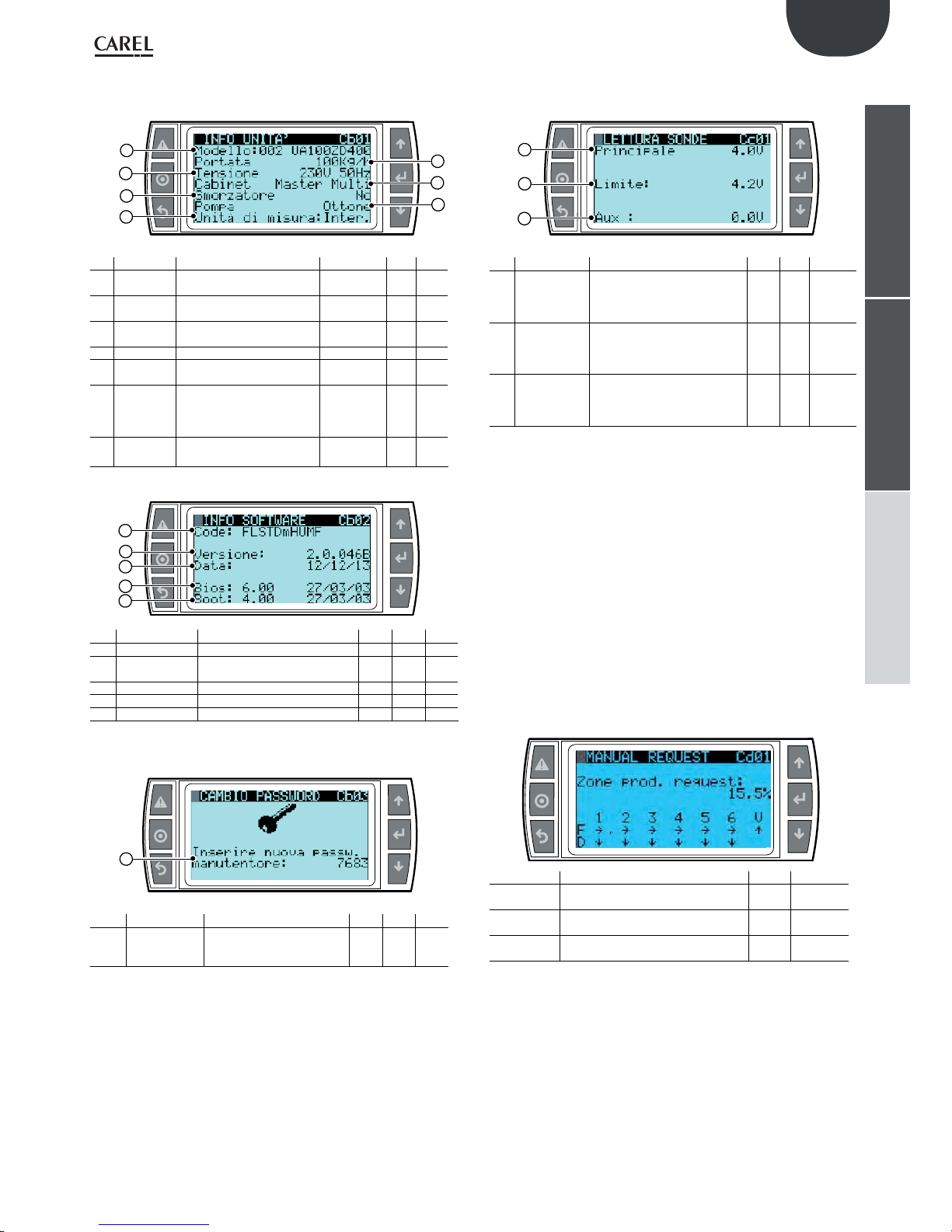
45
ENG
“humiFog multizone - pumping unit” +0300066EN - rel. 1.2 - 10.12.2015
installeruserservice
Submenu b. Unit info 01...03
Info of the unit
1
3
5
2
7
4
6
Ref. Display Description Range Def. Unit
1
Model
Represents the code of the
device
UA....
2
Flow
Represents the flow rate of the
device
kg/h
3
Supply
Identifies the voltage and
frequency of the system
V HZ
4
Cabinet
Identifies the cabinet type Master/multi
5
Samper
Identifies the presence or
absence of the damper
No
6
Pump
Identifies the type of pump
installed
STAINLESS
STEEL
BRASS
SILICON FREE
Steel
7
Measuring
unit
Defines the measuring unit International
Imperial
Inter.
1
3
5
2
4
Ref. Display Description Range Def. Unit
1
Code
Identifies the software code
2
Uersion
Identifies the software version and
the date on which it was updated
3
Date
Identifies the software launch date
4
Bios
Version of the Bios system
5
Boot
Version of the system’s Boot
Change password
1
Ref. Display Description Range Def. Unit
1
Insert new
maintenance
password
Defines the new password of
the maintainer menu
Submenu c . Letture istantanee 01
Main probe reading
1
3
2
Ref. Display Description Range Def. Unit
1
Principale
Display only the signal value read
from the main probe, otherwise
viewable from the Installer menu/
settings area 04
Ohm, mA
o Volt
2
Limite
Display only the signal value read
from the limit probe, otherwise
viewable from the Installer menu/
settings area 05
Ohm, mA
o Volt
3
Aux
Display only the signal value read
from the auxiliary probe, otherwise
viewable from the Installer menu/
settings area 06
Ohm, mA
o Volt
The signals that are not connected are highlighted as “not present” on
the screen.
Submenu d. Manual mode
This is used to control all the outputs and the individual components of
the pumping unit or the Zone Control manually. This function is available
to test the individual components on the unit.
This mode is activated automatically by modifying the status of the
outputs from normal operation, indicated as “AUTO” (“0.0 for the
production request or analogue outputs). To exit manual mode, simply
reset the status of the outputs to “AUTO” (or 0.0). Manual mode is disabled
automatically after 30 minutes of inactivity.
Manual request (screen Cd01)
This is used to override cabinet output so as to test complete operation
of the zone. To do this, simply change the value of “Zone prod.request”
and set the desired request, expressed as a percentage of the rated rack
output.
Display Description Range Def. Unit
Zone prod.
Request:
Zone production request 0-100.0 0 %
F
Fill solenoid valve status step 1-6
(-> = Open, - = closed)
---
D
Drain solenoid valve status step 1-6
(| = Open, - = closed)
---
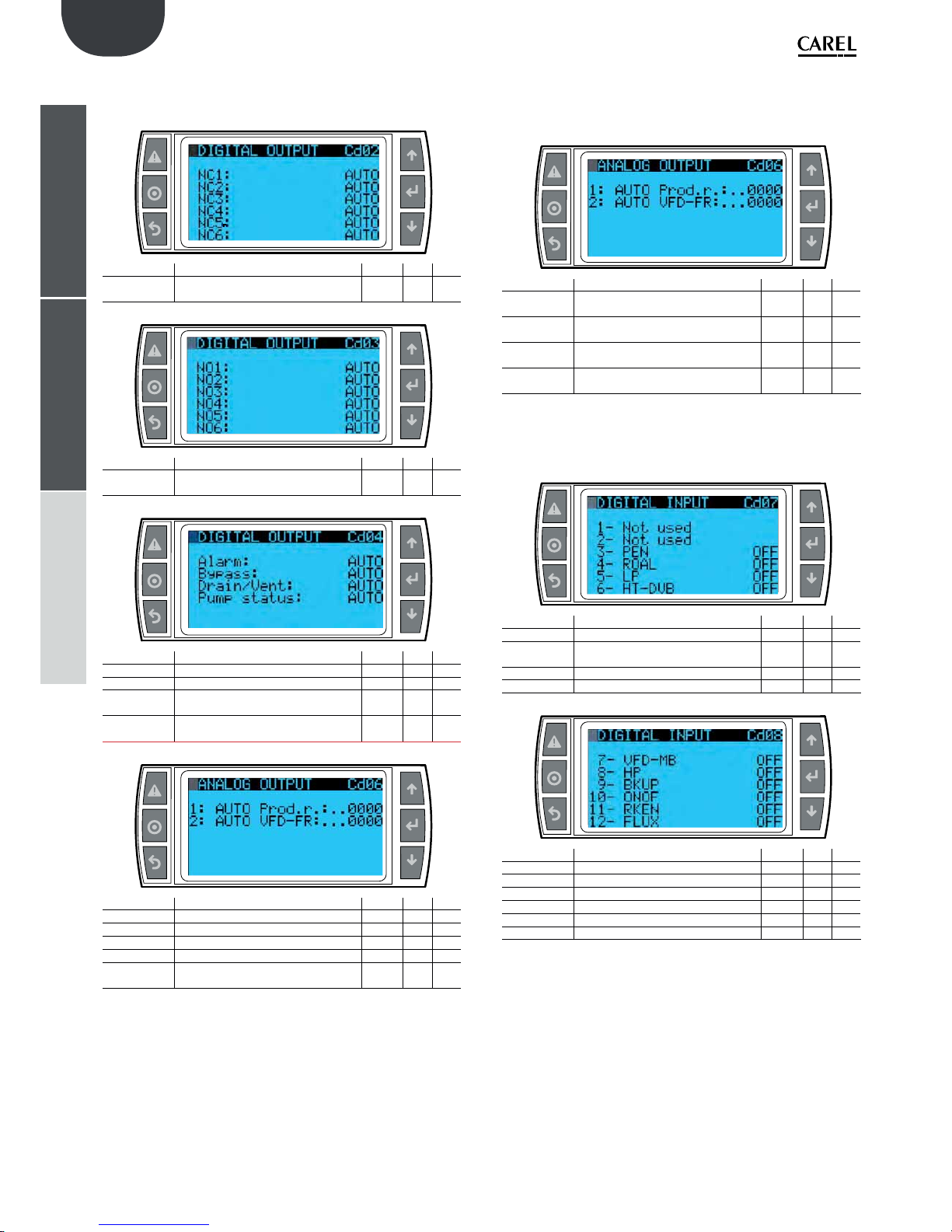
46
ENG
“humiFog multizone - pumping unit” +0300066EN - rel. 1.2 - 10.12.2015
installeruserservice
Digital Output (screens Cd02- Cd05)
This is used to individually activate the digital outputs on the device so as
to test the individual components connected to these.
Display Description Range Def. Unit
NC1… NC6
Spray solenoid valve status setting (NC)
step 1-6
---
Display Description Range Def. Unit
NO1… NO6
Drain solenoid valve status setting (NO)
step 1-6
---
Display Description Range Def. Unit
Alarm
Alarm relay status setting - - -
Bypass
Bypass solenoid valve status setting
Drain/Vent.
Rack vent and drain valve status setting
solenoid
---
Pump
status:
Pump relay status setting - - -
Display Description Range Def. Unit
Rack on/off
Zone status relay setting - - -
Antifreeze
Frost protection activation relay setting
Backup req.
Backup sign of life relay setting - - -
Fill Ev.
Fill solenoid valve status setting - - -
SmartZ.
Drain
Drain solenoid valve status setting in
“SmartZone” mode
---
Analog Output (screen Cd06)
This is used to individually set the status of the analogue outputs on
the controller. Set the function on “ON” to enable control of the desired
analogue output, then set a value other than 0.
Display Description Range Def. Unit
1:
Enable manual control of analogue
output 1
---
Prod.r:
Override current request
(analogue output 1)
0-1000 - -
2:
Enable manual control of analogue
output 2
---
VFD-FR
Override inverter speed request (analogue output 2)
0-1000 - -
Digital input (screens Cd07-Cd08)
Displays the current status, open (ON) or closed (OFF), of the digital inputs.
Display Description Range Def. Unit
3-PEN
Enable pump input status - - -
4- ROAL
Water treatment system alarm input
status
---
5- LP
Low pressure switch status - - -
6- HT-DVB
Safety thermostat status - - -
Display Description Range Def. Unit
7- VFD-MB
Inverter alarm status - - -
8- HP
High pressure switch status - - -
9- BKUP
Request backup activation input status - - -
10- ONOF
Zone on/off input status - - -
11- RKEN
Enable rack status - - -
12- FLUX
Air handling unit flow switch status - - -

47
ENG
“humiFog multizone - pumping unit” +0300066EN - rel. 1.2 - 10.12.2015
installeruserservice
Analog input (screens Cd09-Cd10)
Displays the status of the analogue inputs on the controller.
The value read directly by the input Is displayed, net of any probe limits
and offsets.
Display Description Range Def. Unit
1- Main probe
Value read by the main probe - - -
2- Limit probe
Value read by the limit probe - - -
3- Aux probe
Value read by the auxiliary probe - - -
4- Temp.
Value read by the water temperature probe
---
5- Heat rec.
Heat recovery unit damper status
(if configured as analogue)
---
6- Conductivity
Value read by the conductivity
meter
---
Display Description Range Def. Unit
7- S. pressure
Value read by the pressure probe - - -
8- Rack temp
Value read by the rack temperature
probe
---
Bypass calibration (screen Cd11)
This is used to start the bypass calibration procedure, needed when
replacing the pumps. For details, see the technical leaflet for the
UAKCV0HP* kit.
Display Description Range Def. Unit
Start
calibrat:
Start calibration procedure (Y) - - -
Open/Close
NC solenoid
valves
Close (Y) the system NC solenoid
valves so as to pressurise
---
Pressure
Current pressure - - bar/psi
Flow
Current production - - kg/h –
lb/h
Submenu e. Unit Status 01
Unit state
Views detail information of humiFog
1
2
Ref. Display Description Range Def. Unit
1 System
status
View installation status
StandbyEmpty / StandbyFull
/ Filling / Washing / Emptying
/ Production
2 Standby
empty
View pump
state
Standby / Production increase / Bypass closing / Filling
pressure / Washing pressure
/ Load reduction (production
decrease ramp to obtain a
single EV unload) / Load closing / At regime (production
as well as emptying)
Submenu f. Working hours 01...02
Working hours
1
2
Ref. Display Description Range Def. Unit
1 Pump
View the operating hours of
the pump from the last reset in
read-only mode
000000 h
2 Unit
View the operating hours of
the pump from the last reset in
read-only mode
000000 h
N.B. Within the Maintainer Menu, f submenu, Operating hours, the
02 screen allows to reset the operating hours and shows the date of the
last reset.
1
2
Ref. Display Description Ran-geDef. Unit
1 Reset
pump
counter
Resetting the hourmeter for
pump operation
Si/No
2 Last
reset
date
View the date of the last
resetting
gg/mm/aaaa

48
ENG
“humiFog multizone - pumping unit” +0300066EN - rel. 1.2 - 10.12.2015
installeruserservice
Submenu g. Alarm log
Alarm log
1
2
Ref. Display Description Range Def. Unit
1 N° xxx hour
date
Succession of screens that contain
the two rows displayed on the
left: number of alarm messages,
alarm hour, alarm date and alarm
message.
YES/
No
2 Zona xxx
offline
The history contains 200 alarms, the older ones being overwritten.

49
ENG
“humiFog multizone - pumping unit” +0300066EN - rel. 1.2 - 10.12.2015
installeruserservice
11. TABLE OF ALARMS
When an alarm is activated, the alarm button starts flashing.
In these conditions, pressing the alarm button once displays the type of alarm.
In the case of potentially dangerous alarms, the controller automatically stops production. For some alarm events, the alarm relay is also activated at the
same time as the signal (see the table below).
Alarm Cause Solution Reset Alarm
relay state
Action Note
No valid model selected After replacing the
control, the software
was not configured
correctly
Configure the unit model in use on the Ca01 screen Automatic Active Disabled pro-
duction
It is possible to access
the Ca01 screen directly
from the alarm screen
Nominal rack capacity = 0 The flow rate of the
distribution system
has not been set
correctly
Configure the capacity of the rack on the Bbb01/
Bbb02 screen (according to the pump control type)
Automatic Active Disabled pro-
duction
Bbb01 is used for a
system with flow rate
modulation control,
Bbb02 for a system with
constant pressure It is
possible to access the
configuration screen
directly from the alarm
screen
The number of collectors
is not set
The number of
collectors by which
the steps of the rack
are formed of has not
been set
Set the number of collectors on the Bbb03 screen Automatic Active Disabled pro-
duction
It is possible to access
the Bbb03 screen directly
from the alarm screen
Water treatment plant ID4-IDC1 digital
input on the opened
control.
Check the proper operation of the water treatment
plant. If correct, check on the Bab01 screen that
the input logic coincides with that of the plant
alarm signal - If correct, manually close or open the
entrance with a plank; if the alarm persists, replace
the control
Automatic Active Stop produc-
tion
Low pressure alarm Low pressure at
water inlet
Check the circuit and the pressure of the supplied
water
Automatic Active Stop produc-
tion
High conductivity
warning
The conductivity
of the water has
reached the warning
threshold
Check the water treatment system. If absent, increase the warning threshold on the Bab02 screen
Manual Not active Solo segnala-
zione
High conductivity alarm The conductivity
of the water has
reached the alarm
threshold
Check the water treatment system. If absent, increase the alarm threshold on the Bab02 screen
Manual Active Stop produ-
zione
Bypass high temperature
alarm
Excessive recycling
of the water on the
bypass
Check the operating temperature of the installation
(environment and water); Check if the distribution
system is not obstructed in such a way to cause the
recycling of the water
Automatic Not active Only warning
Inverter alarm Malfunction of
inverter
Check, based on the signalling on the display, the
status of the inverter and eventually replace it
Automatic Active Stop produc-
tion
The alarm is automatically reset on the control.
For the inverter, see
chapter 7 of the inverter’s
manual
High temperature alarm at
the thermostat bypass
Excessive recycling
of the water on the
bypass
Check the proper operation of the water treatment
plant. If correct, check on the Bab01 screen that
the input logic coincides with that of the plant
alarm signal - If correct, manually close or open the
entrance with a plank; if the alarm persists, replace
the control
Manual Active Stop produc-
tion
Low temperature at the
cabinet pump
Water temperature at
inlet lower than 2°C
Reheat the supplied water or the cabinet with a
proper dimensioned heater
Automatic Active Stop produc-
tion
High pressure alarm from
the pressure switch
Flow pressure exceeding 90 bar
Contact CAREL for instructions on checking the
conditions of the bypass valve
Manual Active Stop produc-
tion
High pressure warning
from the presure probe
Flow pressure higher
than 30% of the
nominal pressure
Contact CAREL for instructions on checking the
conditions of the bypass valve
Automatic Not active Only warning
Low pressure warning
from the presure probe
During production,
the flow pressure is
lower than 20 bar
Check the tightnes of the hydraulic circuit at
discharge
Manual Active Stop produc-
tion
Remote area # offline On the Multi-area
pumping station,
the slave unit is not
connected to the
fieldbus network
Check the correct setting (address, enable) of the remote areas connected to the pumping station and
that there are no more areas with the same address.
Then check the wiring and the correct operation of
the optional fieldbus card
Automatic Active Stop produc-
tion
It is possible to check the
correct addressing on the
Bc01 screens (Pumping
station), Bbc01 and
Bbd03 (Remote area)
Offline pumping station On the “Remote area”
cainet, the master
unit is not connected
to the BMS2 port
Check if the address of the remote area corresponds with the one set on the pumping station and
that there are no more other areas with the same
address. Then check the wiring and the correct
operation of the optional fieldbus card
Automatic Active Stop produc-
tion
It is possible to check the
correct addressing on the
Bc01 screens (Pumping
station), Bbc01 and
Bbd03 (Remote area)

50
ENG
“humiFog multizone - pumping unit” +0300066EN - rel. 1.2 - 10.12.2015
installeruserservice
Alarm Cause Solution Reset Alarm
relay state
Action Note
Broken or disconnected
pressure probe
Faulty or incorrectly
connected pressure
probe
Check the connection and the status of the pressure probe
Manual Active Stop produc-
tion
Broken or disconnected
main probe
Broken or incorrectly
connected main
probe
Check the connection and the status of the main
control probe
Manual Active Stop produc-
tion
Broken or disconnected
secondary probe
Broken or incorrectly
connected secondary
(limit) probe
Check the connection and the status of the secondary control probe
Manual Active Stop produc-
tion
Broken or disconnected
auxiliary probe
Broken or incorrectly
connected auxiliary
probe
Check the connection and the status of the auxiliary
probe
Manual Not active Only warning
Broken clock The clock card is not
working properly
Replace the control Manual Active Stop produc-
tion
Faulty or disconnected
bypass temperature probe
Broken or disconnected bypass
temperature probe
Check the correct coupling and operation of the
probe
Manual Active Stop produc-
tion
High humidity alarm The humidity value
detected by the main
probe is higher than
the high humidity
threshold alarm
Check the control parameters to understand if
the production is reduced or increased. Eventually
change the threshold on the Aa01 screen
Manual Not active Only warning The viewing of the alarm
depends on the type of
control used
Low humidity alarm The humidity value
detected by the main
probe is lower than
the low humidity
threshold
Check the control parameters to understand if
the production is reduced or increased. Eventually
change the threshold on the Aa01 screen
Manual Not active Only warning The viewing of the alarm
depends on the type of
control used
High temperature alarm The temperature
value detected by the
main probe is higher
than the high temperature threshold
Check the control parameters to understand if
the production is reduced or increased. Eventually
change the threshold on the Aa01 screen
Manual Not active Only warning The viewing of the alarm
depends on the type of
control used
Low temperature alarm The temperature
value detected by the
main probe is lower
than the low temperature threshold
Check the control parameters to understand if
the production is reduced or increased. Eventually
change the threshold on the Aa01 screen
Manual Not active Only warning The viewing of the alarm
depends on the type of
control used
High humidity alarm from
the limit probe
The humidity value
measured by the limit
probe is higher than
the high humidity
threshold of the limit
probe
Check the control parameters to understand if
the production is reduced or increased. Eventually
change the threshold on the Aa01 screen
Manual Not active Only warning The viewing of the alarm
depends on the type of
control used
Low temperature alarm
from the limit probe
The temperature
value detected by the
limit probe is lower
than the low temperature threshold of
the limit probe
Check the control parameters to understand if
the production is reduced or increased. Eventually
change the threshold on the Aa01 screen
Manual Not active Only warning The viewing of the alarm
depends on the type of
control used
Maintenance: Change oil The pump has
worked for a number
of hours higher than
the maintenance
threshold
Change the oil of the pump Manual Not active Only warning After changing the oil,
reset the operating hours
of the pump from the
Cf02 screen in order to
reset the alarm
The requested flow
exceeds the maximum
available flow
In controlled systems
(Single and MultiArea) with constant
pressure, the total
demand exceeds
the nominal flow of
the pump by 10% or
more
Check if the flows of the steps are correctly set. If
correct, check the dimensioning of the installation
Manual Not active Only warning
pCOe Offline The pCOe is not con-
nected to pCO5+
Check if pCOe is correctly supplied. Then check the
wiring between pCOe and pCO5+.
Manual Active Stop produc-
tion
Actuator 1 offline Remote actuator/
expansion 1 not
connected
Check if the slave cabinet used as a slave is configured correctly. Then check the correct wiring between the J23 port of pCO5+ of the main cabinet and
the BMS2 port of pCO5+ of the cabinet configured
as actuator.
Manual Active Stop produc-
tion
Actuator 2 offline Remote actuator/
expansion 2 not
connected
Check if the slave cabinet used as a slave is configured correctly. Then check the correct wiring between the J23 port of pCO5+ of the main cabinet and
the BMS2 port of pCO5+ of the cabinet configured
as actuator.
Manual Active Stop produc-
tion
Offline supervision system If the On-Off control
by supervisor is used,
the supervisor has
not received requests
for more than 30
seconds.
Check if the supervisor network settings (protocol,
baud rate and slave address) coincide with those of
the Humifog
Automatic Not active Stop produc-
tion
The production is
stopped only if the
adjustment is enabled by
the supervisor

51
ENG
“humiFog multizone - pumping unit” +0300066EN - rel. 1.2 - 10.12.2015
installeruserservice
Alarm Cause Solution Reset Alarm
relay state
Action Note
Broken or disconnected
heat recovery signal
In IEC mode with
analogic heat recovery signal status, the signal is not connected
or out of range
Check the correct connection of the recuperator
at the U5 input, then check that the signal is set
correctly
Manual Active Stop produc-
tion
The signalling is reset
manually: the production
is resumed automatically
as soon as it detects a
valid signal from the
recuperator.
System block With backup and/or
rotation enabled: it
was not possible to
start any of the two
pumping stations
following four
consecutive switch
requests for less than
15 minutes from one
to the other without
any Humifog starting
Check in the Alarm history what the switch has
generated and based on the viewed alarm, follow
the instructions in this table
Manual Active Stop produc-
tion
The alarm that has caused the switch is easily
indetified in the alarm
history (Cg01 screen or
main screen shortcut) as
it is saved immediately
before the “Unit Switch”
event
Rack low temperature The temperature
measured on the rack
is lower than the set
threshold
Check the environment conditions in the vicinity of
the rack, possibly increase the threshold
Manual Active View only If the production reduc-
tion is enabled in case
of rack low temperature
(Bbc05 screen), the
current production is
reduced based on the
measured temperature
Broken or disconnected
rack temperature probe
The rack temperature
probe is broken or
improperly connected
Check the connection and the status of the rack
temperature probe
Manual Not active View only If the production reduc-
tion is enabled in case
of rack low temperature
(Bbc05 screen), the
production reduction
feature is disabled

52
P
VFD
GR
N
L
PE
N
L
GR
N
L
U
V
W
GR
S1S2S3S4S5FSA1
AC
AC
SC
AM
MA
MB
MC
U
V
W
FAN
S1
K_EVFILL(nc)_1
SC
TB - GOB
K (no)
ID6
G0A
FVD - FR
FVD - FC
GA
G0A
GA
NO13
FVD - MC
G
GR N
L
F3 F4F5F1 F2
L1
T1
TR-B
TR-A
L2
T2
400 VA
100 VA
0 [G0A]
0 (G0B)
24 (GB)
24V [GA]
F6 F7
24V [GA]
P
P
F9
24 (GB)
C
C
C
C
H
C
C
C
C
C
F
F
F
F
E
E
E
E
E
AAA
B
B
D
D
C
K (nc)
TB - COM
TB - ROEN
TB-G0A
HT-DVB
LP
HP
FVD - MB
TB - PEN
TB - ROAL
TB - RKEN
TB - FLUX
TB - ONOF
pCO (H)
P
pCO (H)
NOV
G0B
NC1
NO23
NC2
NC3
NC4
NC5
NC6
NO1
NO2
NO3
NO4
NO5
NO6
NO4-NO5-NO6
NO7-NO9
NO11
NO12
NO16-NO17
NO21
NO22
GR
G0BG0BG0BG0BG0BG0B
COM
ROEN
K (COM)
K (NO)
G0AG0AG0A
TRA - 0V
(second.)
(second.)
FLUX
RKEN
ONOF
BKUP
ROAL
PEN
J7 - ID12
J7 - ID11
J7 - ID10
J7 - ID9
J5 - ID4
J5 - ID3
NOL
GR
H
C
NO1-NO2-NO 3- NO1(pCOe)
NO10- NO3(pCOe)
NO18-NO19
NO14-NO1 5- NO2(p COe)
NO20- NO4(pCOe)
MORSETTIERA UTENTE / USER TERMINAL BOARD (use copper conductor only)
ENG
“humiFog multizone - pumping unit” +0300066EN - rel. 1.2 - 10.12.2015
installeruserservice
12. WIRING DIAGRAMS
12.1 Wiring diagram humiFog multizone - Master - CE - MONOFASE
TORQUE FORCE TERMINALS (Nm)
SINGLE TERMINAL: 5,3 min -> 7 max
DOUBLE TERMINAL: 5,3 min -> 7 max
TERMINAL WITH FUSE: 13 min -> 16 max
GROUND TERMINAL: 13 min -> 16 max

53
GA
TB - NC4
TB - NC5
TB - NC6
TB - NC3
TB - NC2
TB - NC1
DVB
TB - NOL
TB - NO6
TB - NO5
TB - NO4
TB - NO3
TB - NO2
TB - NO1
TB - N C1
TB - NO1
TB - NC4
TB - NO4
ENG
“humiFog multizone - pumping unit” +0300066EN - rel. 1.2 - 10.12.2015
installeruserservice
FORZA DI SERRAGGIO MORSETTI pCO5+
TORQUE FORCE TERMINALS pCO5+
(Nm) = 0,5 min -> 0,6 max
FUSES TABLEI:
F1-F2 -> 1A T 5x20 250V
F3-F4 -> 4A T 5x20 250V
F5 -> 4A T 5x20 250V
F6-F7 -> 12A T 10,3x38 500V (UA100/200*****)
F6-F7 -> 20A T 10,3x38 500V (UA320/480*****)
F6-F7 -> 25A T 10,3x38 500V (UA600*****)
F9 -> 16A T 10,3x38 500V (UA100/460****)
F9 -> 25A T 10,3x38 500V (UA600*****)

54
P
VFD
GR
U
V
W
GR
S1S2S3
S4
S5
FSA1AC
AC
SC
AM
MA
MB
MC
U
V
W
FAN
S1
K_EVFILL(nc)_1
SC
TB - GOB
K (no)
ID6
G0A
FVD - FR
FVD - FC
GA
G0A
GA
NO13
FVD - MC
F3
F4
F5
F1
F2
TR-B
TR-A
600 VA
100 VA
0 [G0A]
0 (G0B)
24 (GB)
24V [GA]
24V [GA]
P
P
F9
24 (GB)
C
C
C
C
C
C
C
F
F
F
F
E
E
E
E
E
AAA
B
B
D
D
C
K (nc)
TB - COM
TB - R OEN
TB-G0A
HT-DVB
LP
HP
FVD - MB
TB - PEN
TB - ROAL
TB - RKEN
TB - FLUX
TB - ONOF
pCO (H)
P
pCO (H)
NOV
G0B
NC1
NO23
NC2
NC3
NC4
NC5
NC6
NO1
NO2
NO3
NO4
NO5
NO6
NO4-NO5-NO6
NO7-NO9
NO11
NO12
NO16-NO17
NO21
NO22
GR
G0B
G0B
G0BG0B
G0BG0B
COM
ROEN
K (COM)
K (NO)
G0AG0A
G0A
TRA - 0V
(second.)
(second.)
FLUX
RKEN
ONOF
BKUP
ROAL
PEN
J7 - ID12
J7 - ID11
J7 - ID10
J7 - ID9
J5 - ID4
J5 - ID3
NOL
GR
H
C
NO1-NO2-NO3- NO1(pCOe)
NO10 - NO 3( p COe)
NO18-NO19
NO14-NO15- NO2(pCOe)
NO20 - NO 4( p COe)
L3 L2
GR
L1
L2
T2
C
C
C
H
T3
L3
G
L1
T1
C
B
F6
F8
F7
C
L3
L2
L1
PE
GR
L3
L2
L1
L1
L2
L3
MORSETTIERA UTENTE / USER TERMINAL BOARD (use copper conductor only)
ENG
“humiFog multizone - pumping unit” +0300066EN - rel. 1.2 - 10.12.2015
installeruserservice
12.2 Wiring diagram humiFog multizone - Master - CE - TRIFASE (solo per UA10K***)
TORQUE FORCE TERMINALS (Nm)
SINGLE TERMINAL: 5,3 min -> 7 max
DOUBLE TERMINAL: 5,3 min -> 7 max
TERMINAL WITH FUSE: 13 min -> 16 max
GROUND TERMINAL: 13 min -> 16 max

55
GA
TB - NC4
TB - NC5
TB - NC6
TB - NC3
TB - NC2
TB - NC1
DVB
TB - NOL
TB - NO6
TB - N O5
TB - NO4
TB - NO3
TB - N O2
TB - NO1
TB - NC1
TB - NO1
TB - NC4
TB - NO4
ENG
“humiFog multizone - pumping unit” +0300066EN - rel. 1.2 - 10.12.2015
installeruserservice
FORZA DI SERRAGGIO MORSETTI pCO5+
TORQUE FORCE TERMINALS pCO5+
(Nm) = 0,5 min -> 0,6 max
FUSES TABLEI:
F1-F2 -> 1A T 10,3x38 500V
F3-F4 -> 4A T 10,3x38 500V
F5 -> 4A T 5x20 250V
F6-F7-F8 -> 25A F 10,3x38 500V
F9 -> 25A T 10,3x38 500V

56
P
VFD
GR
N
LPEN
L
GR
N
L
U
V
W
GR
S1S2S3S4S5FSA1
AC
AC
SC
AM
MA
MB
MC
U
V
W
FAN
S1
K_EVFILL(nc)_1
SC
TB - GOB
K (no)
ID6
G0A
FVD - FR
FVD - FC
GA
G0A
GA
NO13
FVD - MC
GR N
L
F3 F4F5F1 F2
L1
T1
TR-B
TR-A
L2
T2
400 VA
100 VA
0 [G0A]
0 (G0B)
24 (GB)
24V [GA]
F6 F7
24V [G A]
P
P
F9
24 (GB)
K (nc)
TB - COM
TB - ROEN
TB-G0A
HT-DVB
LP
HP
FVD - MB
TB - PEN
TB - R OAL
TB - RKEN
TB - FLUX
TB - ONOF
pCO (H)
P
pCO (H)
NOV
G0B
NC1
NO23
NC2
NC3
NC4
NC5
NC6
NO1
NO2
NO3
NO4
NO5
NO6
NO4-NO5-NO6
NO7-NO9
NO11
NO12
NO16-NO17
NO21
NO22
GR
G0BG0B
G0B
G0B
G0BG0B
COM
ROEN
K (COM)
K (NO)
G0AG0A
G0A
TRA - 0V
(second.)
(second.)
FLUX
RKEN
ONOF
BKUP
ROAL
PEN
J7 - ID12
J7 - ID11
J7 - ID10
J7 - ID9
J5 - ID4
J5 - ID3
NOL
GR
PONTI AVVITATI / TERMINAL JUMPER
NO1-NO 2-NO3- NO 1(pCOe)
NO10- NO3(pCOe)
NO18-NO19
NO14- NO15- NO2(p COe)
NO20- NO4(pCOe)
MORSETTIERA UTENTE / USER TERMINAL BOARD (use copper conductor only)
ENG
“humiFog multizone - pumping unit” +0300066EN - rel. 1.2 - 10.12.2015
installeruserservice
12.3 Wiring diagram humiFog multizone - Master - UL - MONOFASE
TORQUE FORCE TERMINALS (Nm)
SINGLE TERMINAL: 5,3 min -> 7 max
DOUBLE TERMINAL: 5,3 min -> 7 max
TERMINAL WITH FUSE: 13 min -> 16 max
GROUND TERMINAL: 13 min -> 16 max

57
GA
TB - NC4
TB - NC5
TB - NC6
TB - NC3
TB - NC2
TB - NC1
DVB
TB - NOL
TB - NO6
TB - NO5
TB - NO4
TB - NO3
TB - NO2
TB - NO1
TB - NC1
TB - NO1
TB - NC4
TB - NO4
ENG
“humiFog multizone - pumping unit” +0300066EN - rel. 1.2 - 10.12.2015
installeruserservice
FORZA DI SERRAGGIO MORSETTI pCO5+
TORQUE FORCE TERMINALS pCO5+
(Pound Inches) = 4,4 min -> 5,3 max
FUSES TABLEI:
F1-F2 -> 1A T 5x20 250V
F3-F4 -> 4A T 5x20 250V
F5 -> 4A T 5x20 250V
F6-F7 -> 12A T 10,3x38 500V (UA100/200*****)
F6-F7 -> 20A T 10,3x38 500V (UA320/480*****)
F6-F7 -> 25A T 10,3x38 500V (UA600*****)
F9 -> 20A F 10,3x38 500V (UA100/460****)
F9 -> 30A F 10,3x38 500V (UA600****)

58
P
VFD
GR
U
V
W
GR
S1S2S3
S4
S5
FSA1AC
AC
SC
AM
MA
MB
MC
U
V
W
FAN
S1
K_EVFILL(nc)_1
SC
TB - GOB
K (no)
ID6
G0A
FVD - FR
FVD - FC
GA
G0A
GA
NO13
FVD - MC
F3
F4
F5
F1
F2
TR-B
TR-A
600 VA
100 VA
0 [G0A]
0 (G0B)
24 (GB)
24V [G A]
24V [GA]
P
P
F9
24 (GB)
C
C
C
C
C
C
C
F
F
F
F
E
E
E
E
E
AAA
B
B
D
D
C
K (nc)
TB - COM
TB - R OEN
TB-G0A
HT-DVB
LP
HP
FVD - MB
TB - PEN
TB - ROAL
TB - RKEN
TB - FLUX
TB - ONOF
pCO (H)
P
pCO (H)
NOV
G0B
NC1
NO23
NC2
NC3
NC4
NC5
NC6
NO1
NO2
NO3
NO4
NO5
NO6
NO4-NO5-NO6
NO7-NO9
NO11
NO12
NO16-NO17
NO21
NO22
GR
G0BG0BG0BG0BG0BG0B
COM
ROEN
K (COM)
K (NO)
G0A
G0AG0A
TRA - 0V
(second.)
(second.)
FLUX
RKEN
ONOF
BKUP
ROAL
PEN
J7 - ID12
J7 - ID11
J7 - ID10
J7 - ID9
J5 - ID4
J5 - ID3
NOL
GR
H
C
NO1-NO2-NO3- NO1(pCOe)
NO10- NO3( p C O e )
NO18-NO19
NO14-NO1 5- NO2 (p COe)
NO20- NO4( p C O e )
L3 L2GR
L1
L2
T2
C
C
C
H
T3
L3
G
L1
T1
C
B
F6F8
F7
C
L3
L2
L1
PE
GR
L3
L2
L1
L1
L2
L3
MORSETTIERA UTENTE / USER TERMINAL BOARD (use copper conductor only)
ENG
“humiFog multizone - pumping unit” +0300066EN - rel. 1.2 - 10.12.2015
installeruserservice
12.4 Wiring diagram humiFog multizone - Master - UL - TRIFASE
TORQUE FORCE TERMINALS (Nm)
SINGLE TERMINALS: 5,3 min -> 7 max
DOUBLE TERMINAL: 5,3 min -> 7 max
TERMINAL WITH FUSE: 13 min -> 16 max
GROUND TERMINAL: 13 min -> 16 max

59
GA
TB - NC4
TB - NC5
TB - NC6
TB - NC3
TB - NC2
TB - NC1
DVB
TB - N OL
TB - N O6
TB - N O5
TB - N O4
TB - N O3
TB - N O2
TB - N O1
TB - NC1
TB - NO1
TB - NC4
TB - NO4
ENG
“humiFog multizone - pumping unit” +0300066EN - rel. 1.2 - 10.12.2015
installeruserservice
FORZA DI SERRAGGIO MORSETTI pCO5+
TORQUE FORCE TERMINALS pCO5+
(Pound Inches) = 4,4 min -> 5,3 max
FUSES TABLEI:
F1-F2 -> 1A T 10,3x38 500V
F3-F4 -> 4A T 10,3x38 500V
F5 -> 4A T 5x20 250V
F6-F7-F8 -> 25A F 10,3x38 500V
F9 -> 30A F 10,3x38 500V
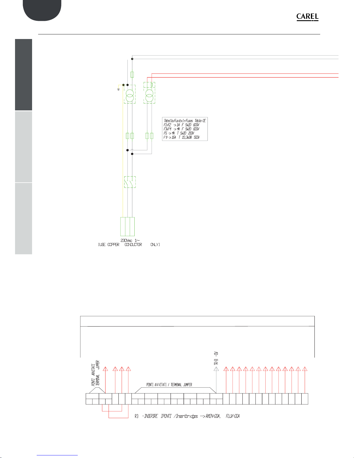
60
TB - GOB
G
GR N
L
F3
F4F5F1 F2
L1
T1
TR-B
TR-A
L2
T2
400 VA
100 VA
0 [G0A]
0 (G0B)
24 (GB)
24V [GA]
F9
24 (GB)
C
C
C
C
H
C
C
C
C
C
D
D
C
NOV
G0B
NC1
NO23
NC2
NC3
NC4
NC5
NC6
NO1
NO2
NO3
NO4
NO5
NO6
NO1-NO2-NO3
NO4-NO5-NO6
NO7-NO9
NO10
NO11
NO12
NO14-NO15
NO16-NO17
NO18-NO19
NO20
NO21
NO22
G0B
G0BG0B
G0B
G0B
G0B
G0AG0A
J4 - VG0
FLUX
RKEN
ONOF
J7 - ID12
J7 - ID11
J7 - ID10
C
MORSETTIERA UTENTE / USER TERMINAL BOARD (use copper conductor only)
ENG
“humiFog multizone - pumping unit” +0300066EN - rel. 1.2 - 10.12.2015
installeruserservice
12.5 Wiring diagram humiFog multizone - Slave - CE
TORQUE FORCE TERMINALS (Nm)
SINGLE TERMINAL: 0,6 min -> 0,8 max
DOUBLE TERMINAL: 0,6 min -> 0,8 max
TERMINAL WITH FUSE: 1,5 min -> 1,8 max
GROUND TERMINAL: 1,5 min -> 1,8 max

61
TB - N O1
TB - N O2
TB - N O3
TB - N O4
TB - N O5
TB - N O6
TB - N OV
TB - NC4
TB - NC5
TB - NC6
TB - NC1
TB - NC2
TB - NC3
TB - RKEN
TB - FLUX
TB - ONOF
TB - BKUP
pCO (H)
P
pCO (H)
TB - G0A
ENG
“humiFog multizone - pumping unit” +0300066EN - rel. 1.2 - 10.12.2015
installeruserservice
FORZA DI SERRAGGIO MORSETTI pCO5+
TORQUE FORCE TERMINALS pCO5+
(Pound Inches) = 0,5 min -> 0,6 max
FUSES TABLEI:
F1-F2 -> 1A F 5x20 600V
F3-F4 -> 4A F 5x20 600V
F5 -> 4A T 5x20 250V
F9 -> 16A T 10,3x38 500V

62
TB - GOB
G
GR N
L
F3
F4F5F1
F2
L1
T1
TR-B
TR-A
L2
T2
400 VA
100 VA
0 [G0A]
0 (G0B)
24 (GB)
24V [GA]
NOV
G0B
NC1
NO23
NC2
NC3
NC4
NC5
NC6
NO1
NO2
NO3
NO4
NO5
NO6
NO1-NO2-NO3
NO4-NO5-NO6
NO7-NO9
NO10
NO11
NO12
NO14-NO15
NO16-NO17
NO18-NO19
NO20
NO21
NO22
G0B
G0BG0BG0BG0B
G0BG0A
G0A
J4 - VG0
FLUX
RKEN
ONOF
J7 - ID12
J7 - ID11
J7 - ID10
C
F9
24 (GB)
C
C
C
C
H
C
C
C
C
C
D
D
C
TB - RKEN
TB - FLUX
TB - ONOF
TB - BKUP
pCO (H)
P
pCO (H)
TB - G0 A
MORSETTIERA UTENTE / USER TERMINAL BOARD (use copper conductor only)
ENG
“humiFog multizone - pumping unit” +0300066EN - rel. 1.2 - 10.12.2015
installeruserservice
12.6 Wiring diagram humiFog multizone - Slave - UL
TORQUE FORCE TERMINALS (Nm)
SINGLE TERMINAL: 0,6 min -> 0,8 max
DOUBLE TERMINAL: 0,6 min -> 0,8 max
TERMINAL WITH FUSE: 1,5 min -> 1,8 max
GROUND TERMINAL: 1,5 min -> 1,8 max

63
TB - N O1
TB - N O2
TB - N O3
TB - N O4
TB - N O5
TB - N O6
TB - N OV
TB - NC4
TB - NC5
TB - NC6
TB - NC1
TB - NC2
TB - NC3
ENG
“humiFog multizone - pumping unit” +0300066EN - rel. 1.2 - 10.12.2015
installeruserservice
FORZA DI SERRAGGIO MORSETTI pCO5+
TORQUE FORCE TERMINALS pCO5+
(Pound Inches) = 0,5 min -> 0,6 max
FUSES TABLEI:
F1-F2 -> 1A F 5x20 600V
F3-F4 -> 4A F 5x20 600V
F5 -> 4A T 5x20 250V
F9 -> 16A T 10,3x38 500V

64
ENG
“humiFog multizone - pumping unit” +0300066EN - rel. 1.2 - 10.12.2015
Notes:


CAREL INDUSTRIES - Headquarters
Via dell’Industria, 11 - 35020 Brugine - Padova (Italy)
Tel. (+39) 049.9716611 - Fax (+39) 049.9716600
e-mail: carel@carel.com - www.carel.com
Agenzia / Agency:
“humiFog multizone - pumping unit” +0300066EN - rel. 1.2 - 10.12.2015
 Loading...